James H
-
Posts
6,112 -
Joined
-
Last visited
Content Type
Profiles
Forums
Gallery
Events
Everything posted by James H
-

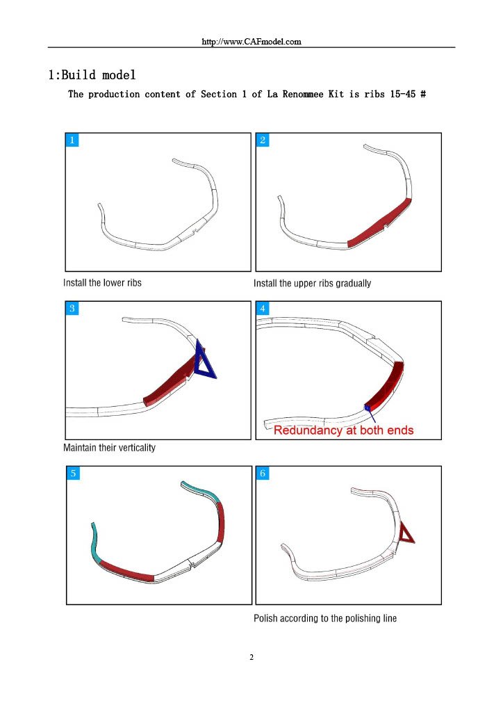
kit review 1:48 La Renommée 1744 - CAF Model
James H replied to James H's topic in REVIEWS: Model kits
Depending on where you are located, buying in chapters helps to negate import duty due to breaking down into smaller consignments.- 16 replies
-
- 3
-

-
- cafmodel
- la renommee
- (and 1 more)
-
I don't do them as I'm absolutely crap at figure painting. Doing the ones for Surprise was through necessity only.
-
I like to use Plastikote matt white for a finish coat.
-
If you ever lose any pegs, just cut them from the sheet yourself? That's what I inevitably do if I lose any while building the prototypes.
- 18 replies
-
- 2
-
-
- Sherbourne
- Vanguard Models
- (and 1 more)
-
kit review 1:48 La Renommée 1744 - CAF Model
James H replied to James H's topic in REVIEWS: Model kits
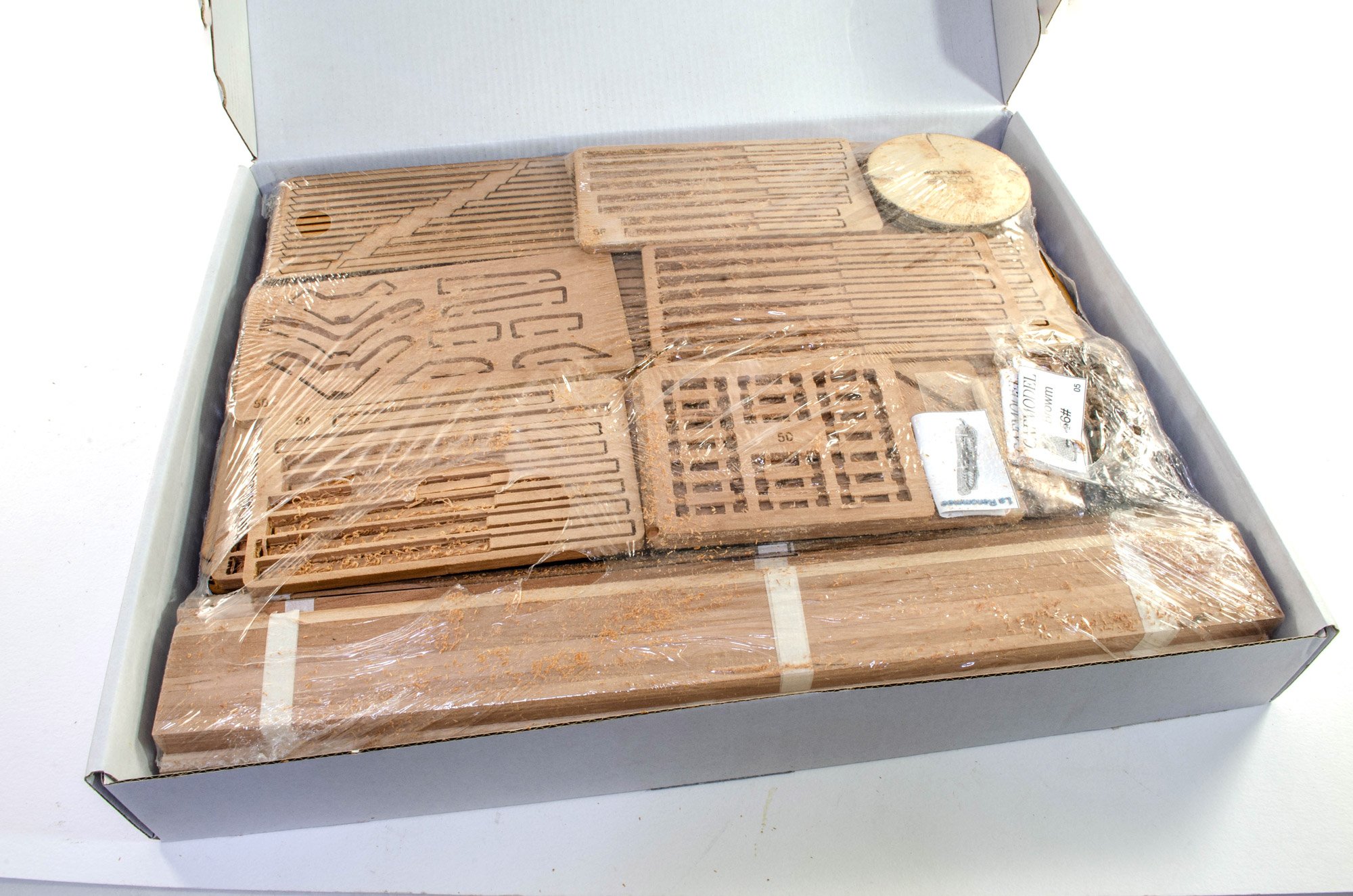
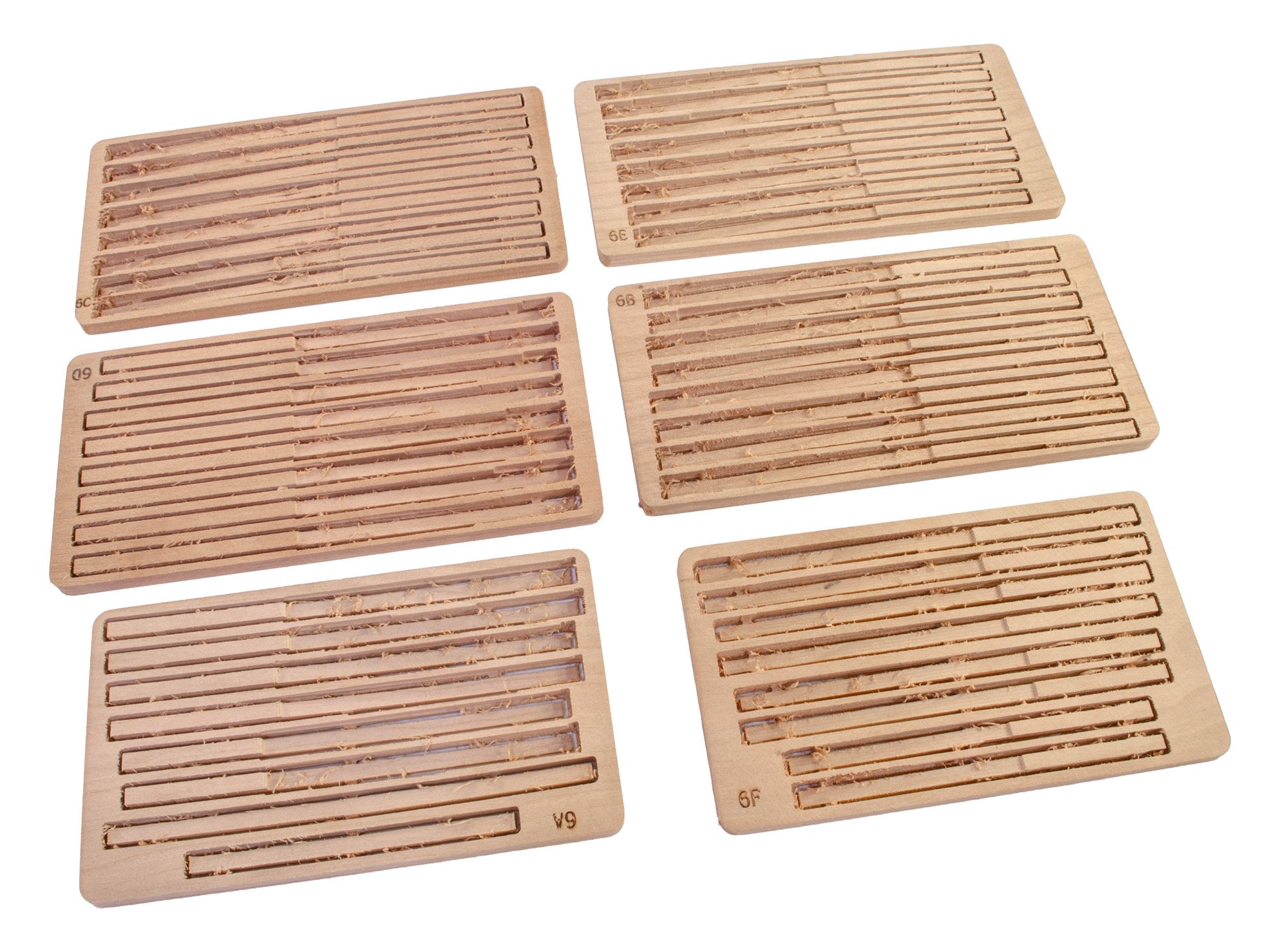
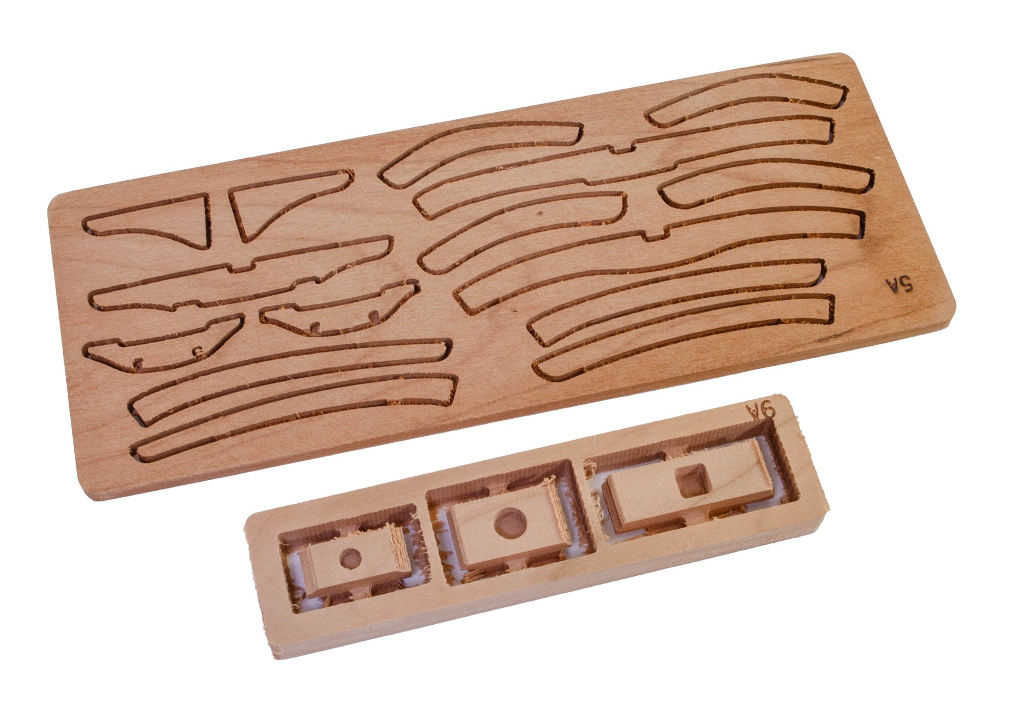
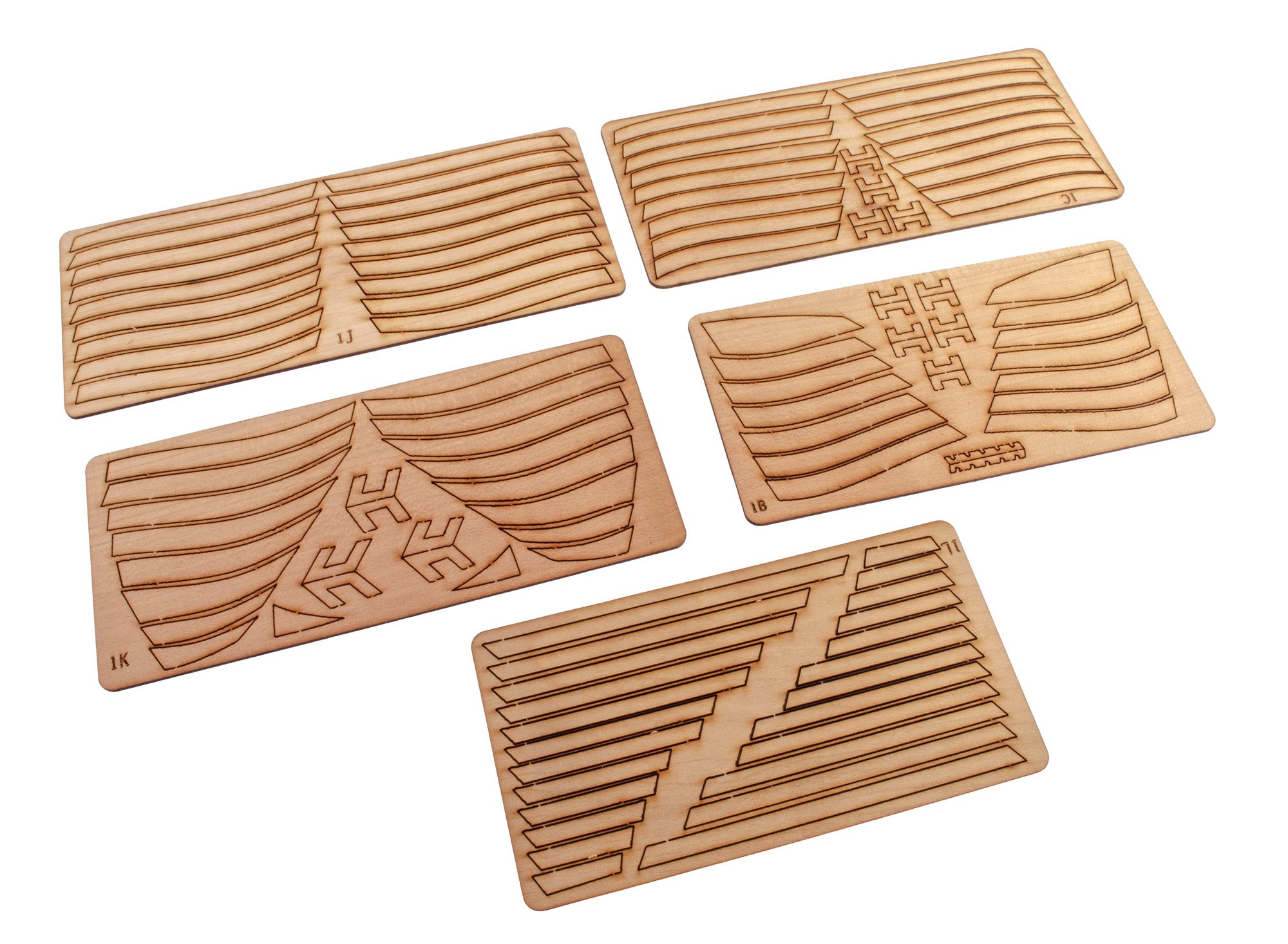
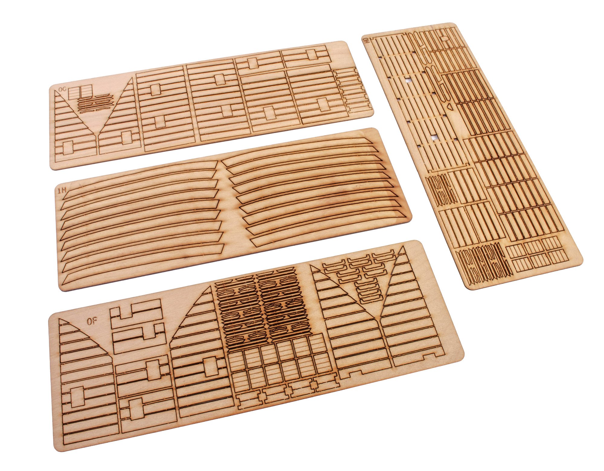
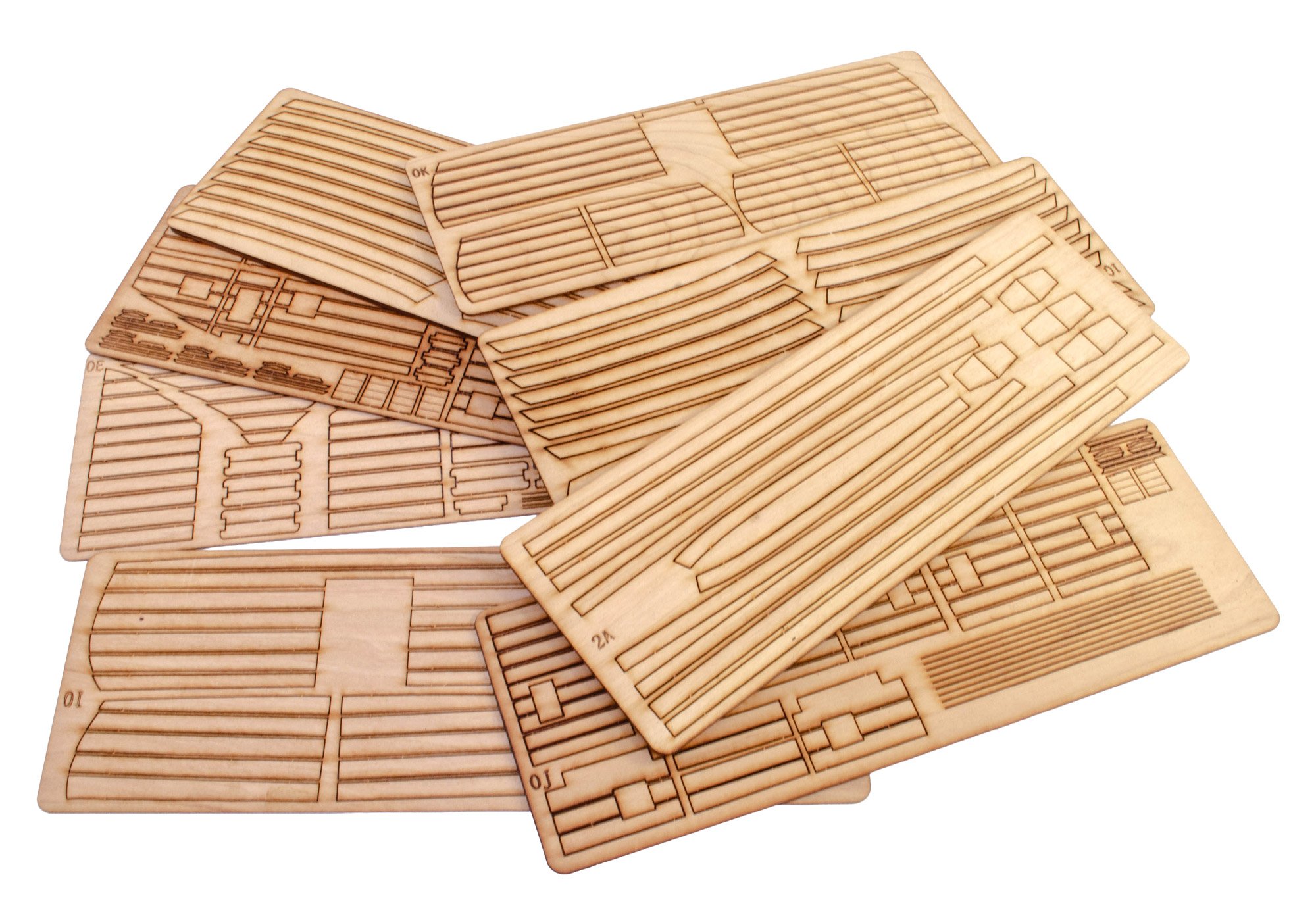
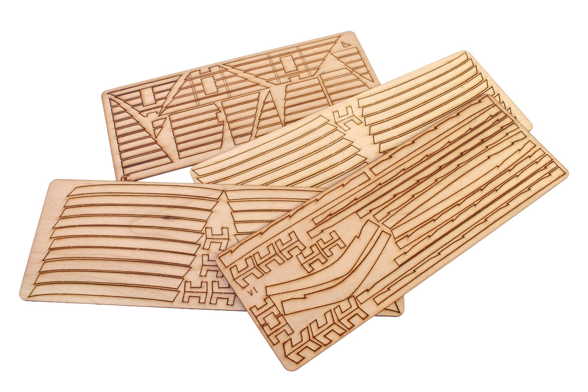
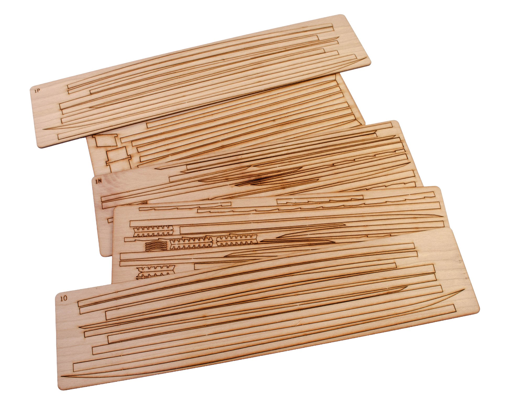
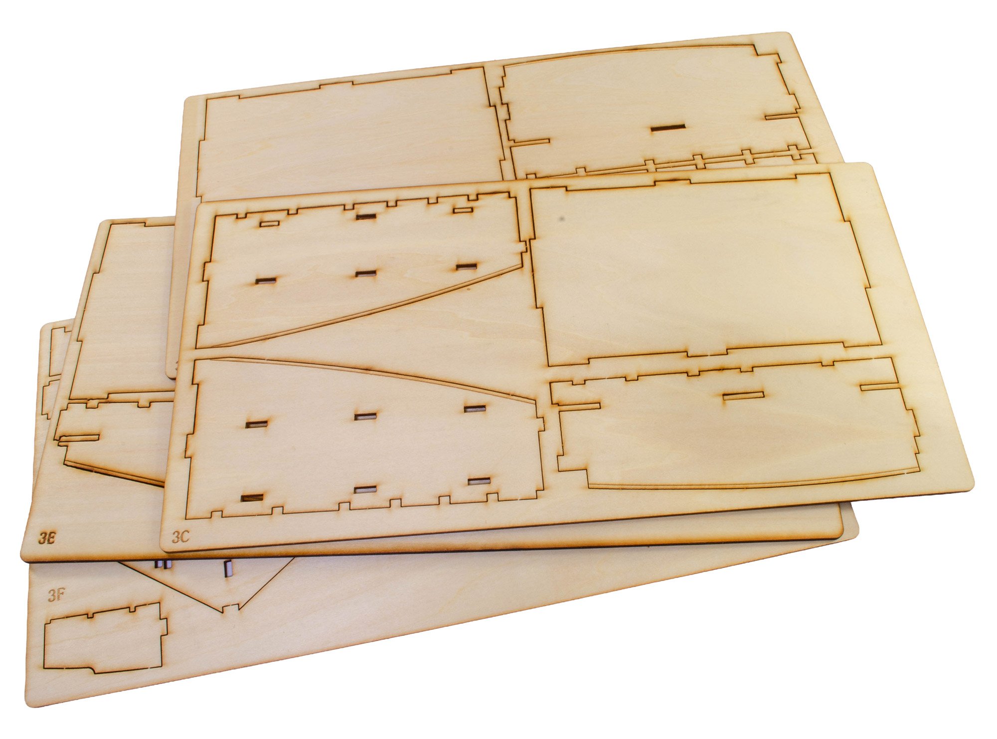
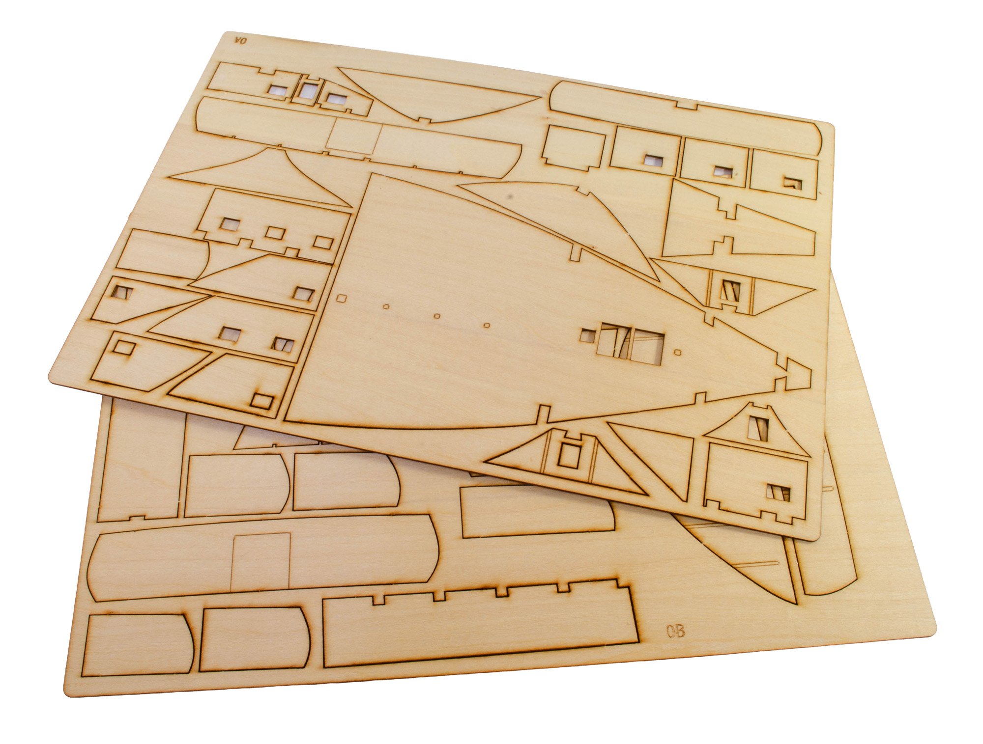
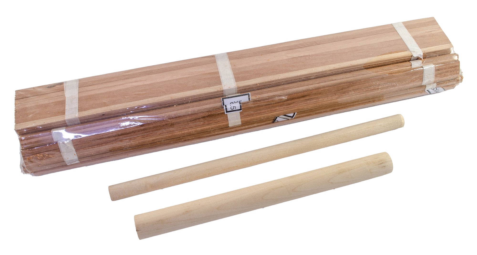
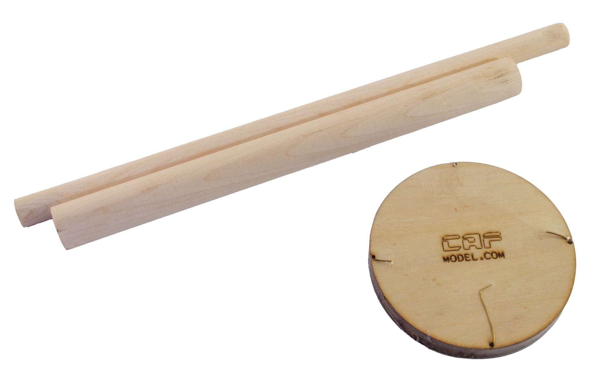
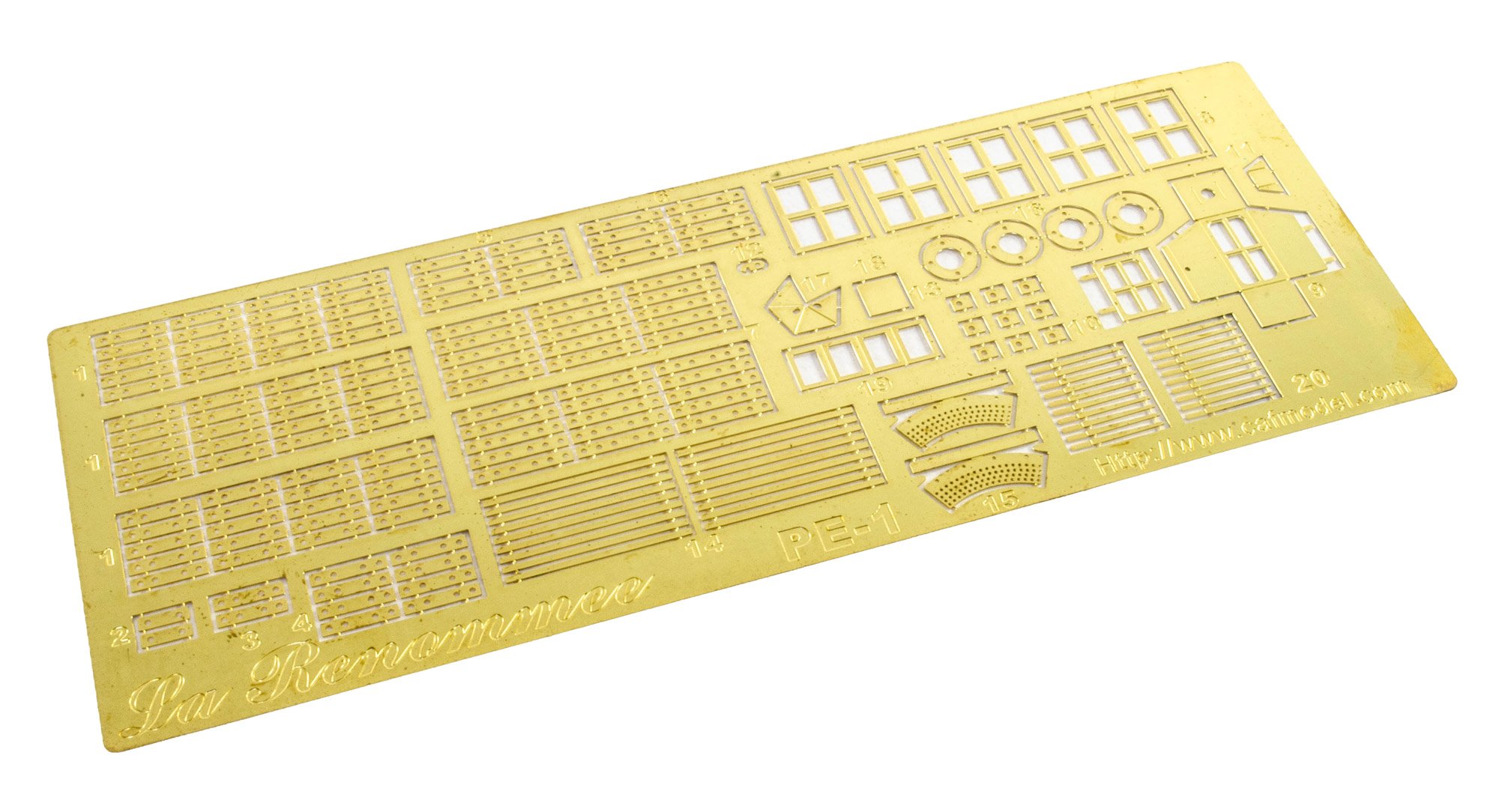
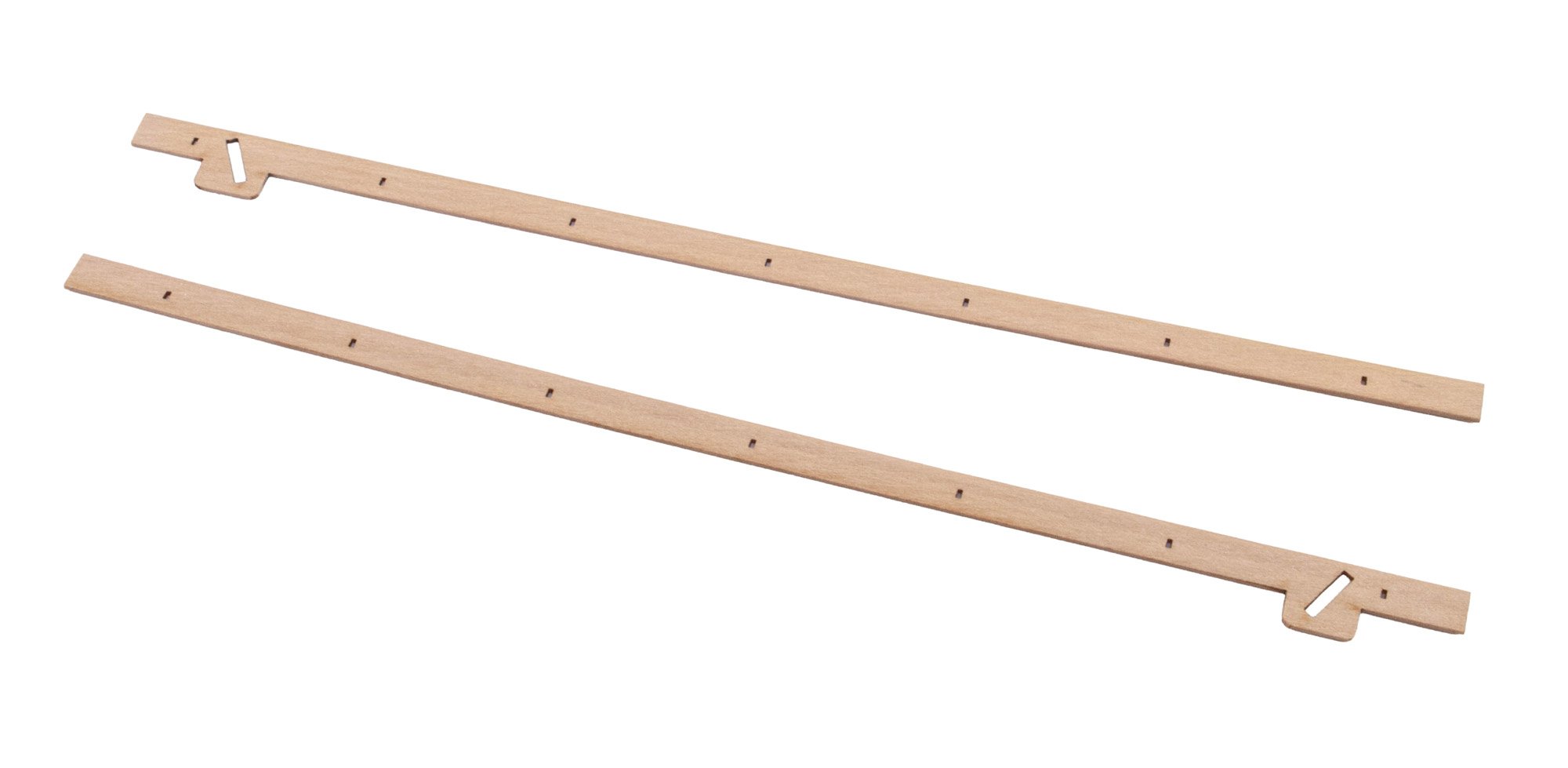
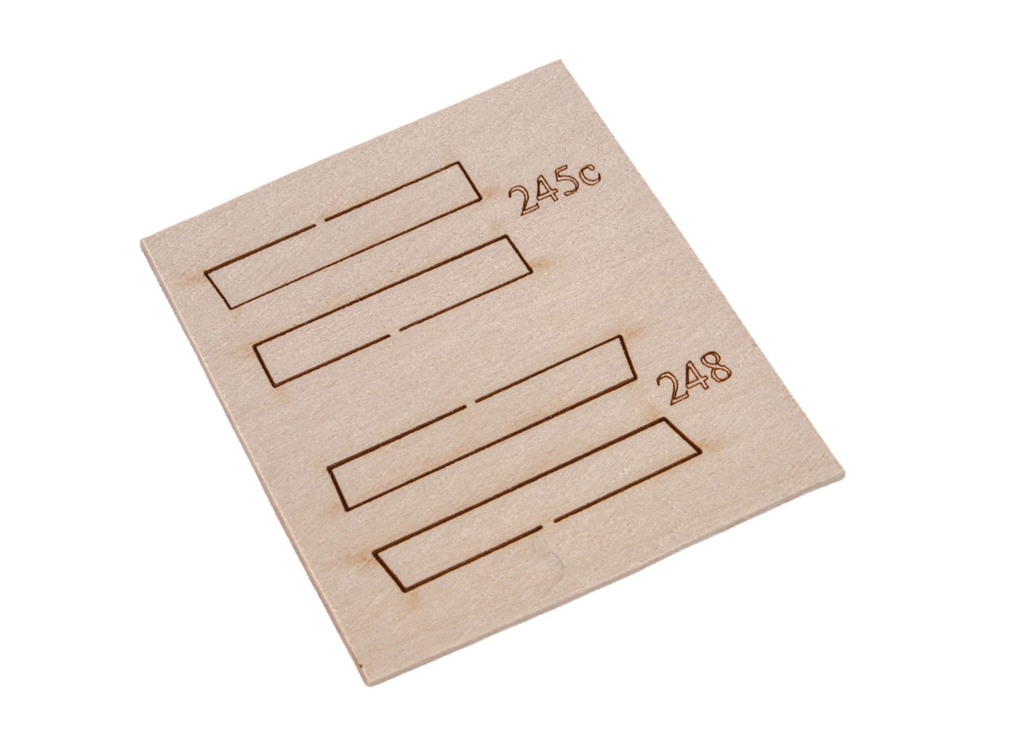
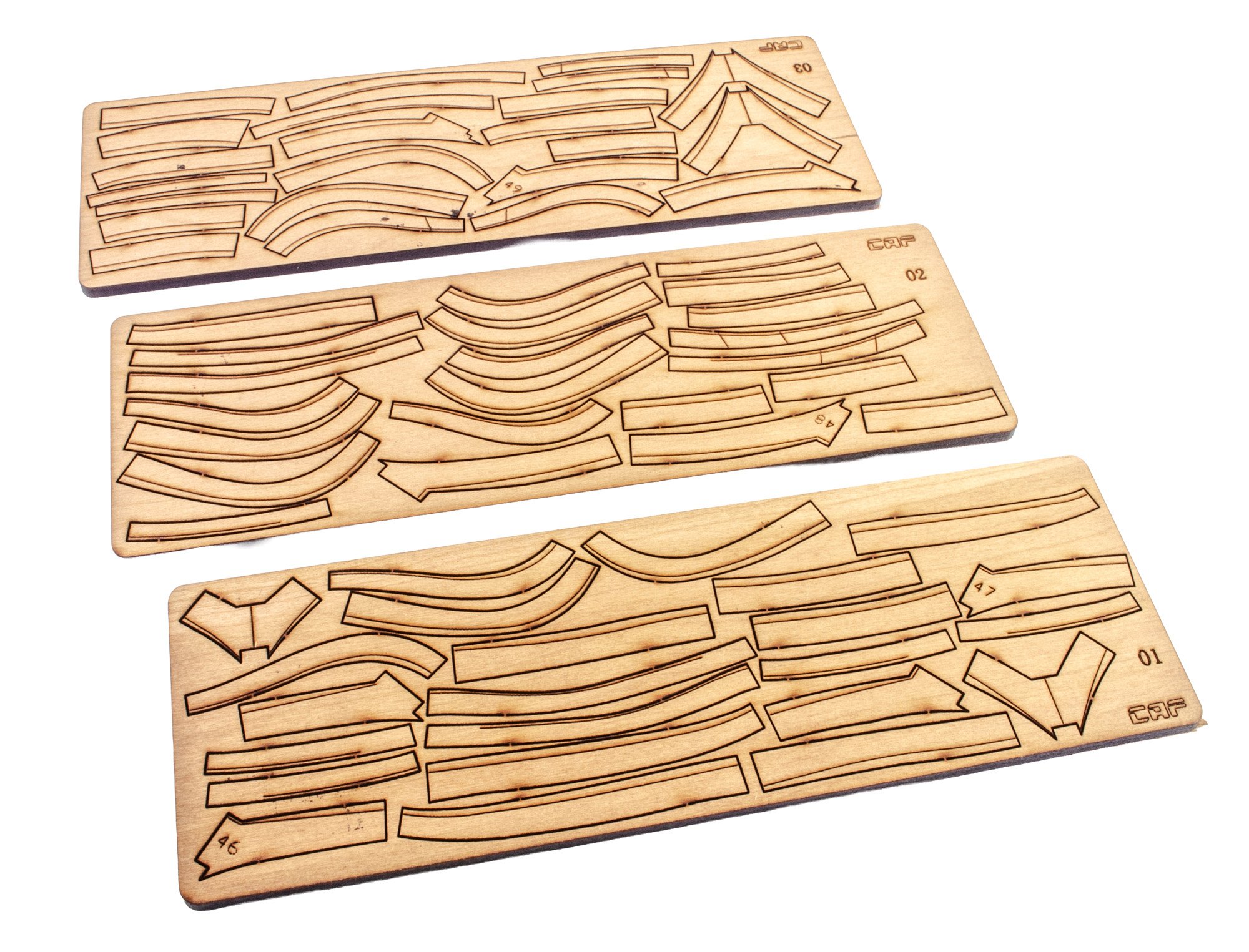
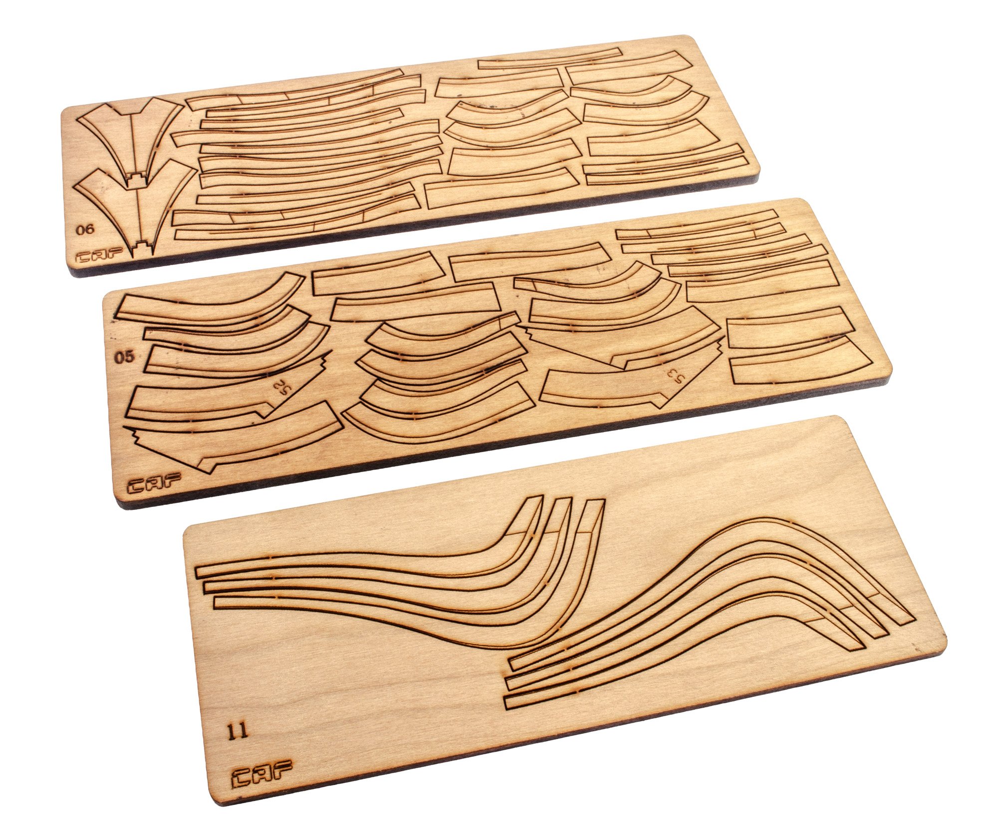
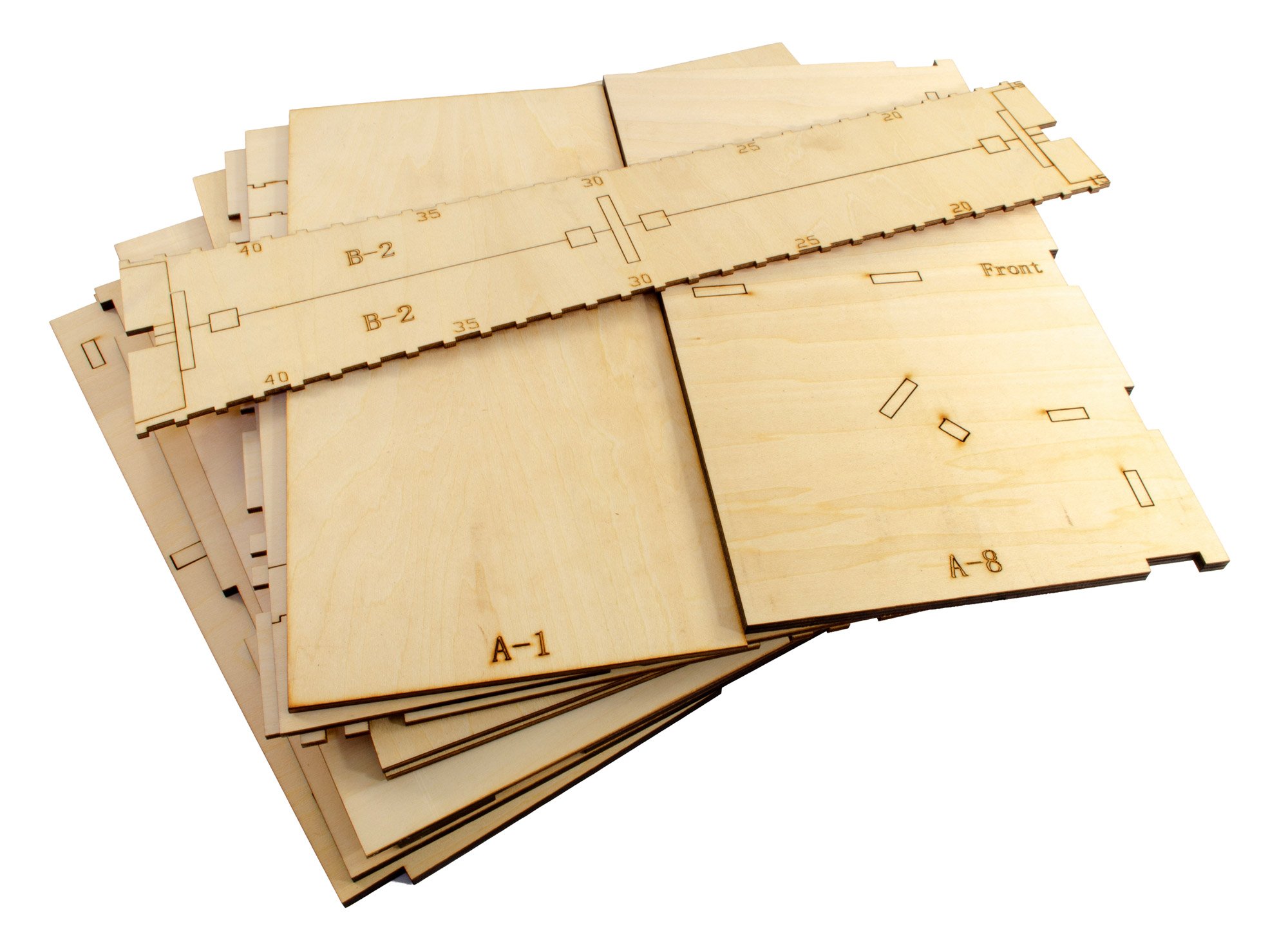
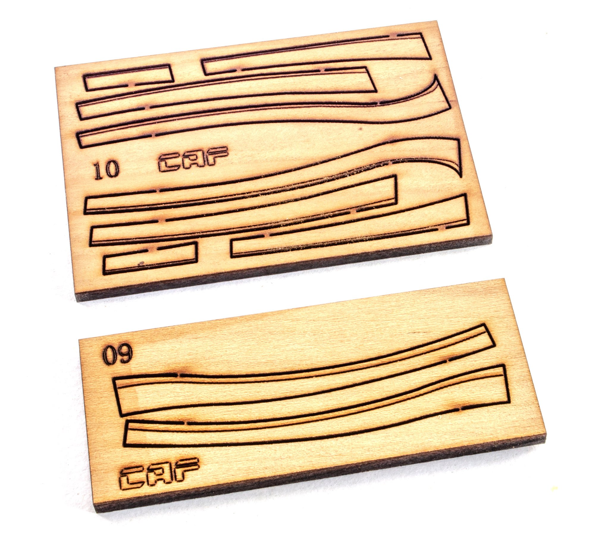
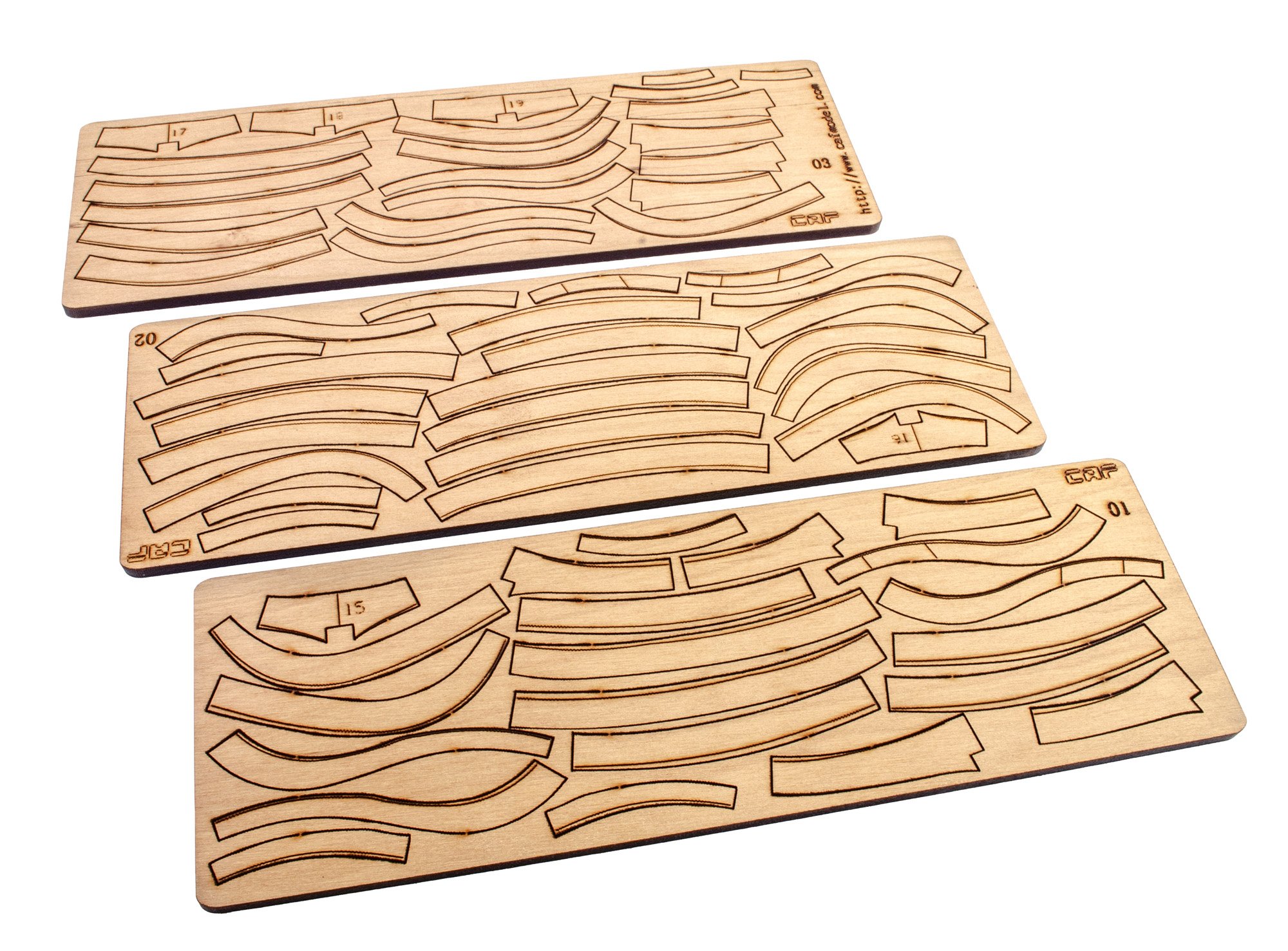
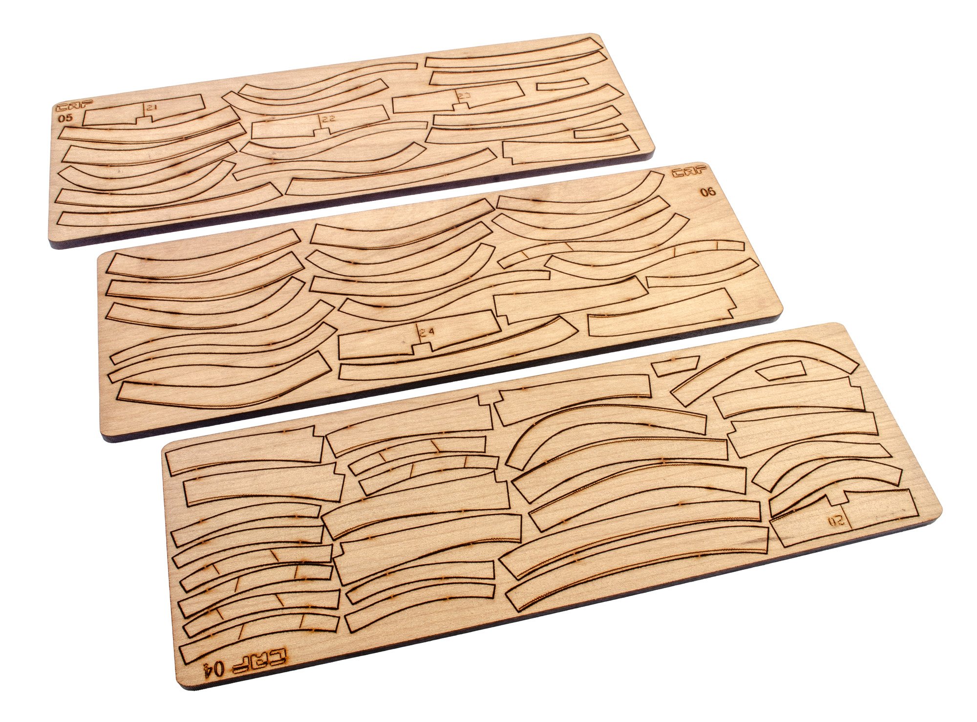
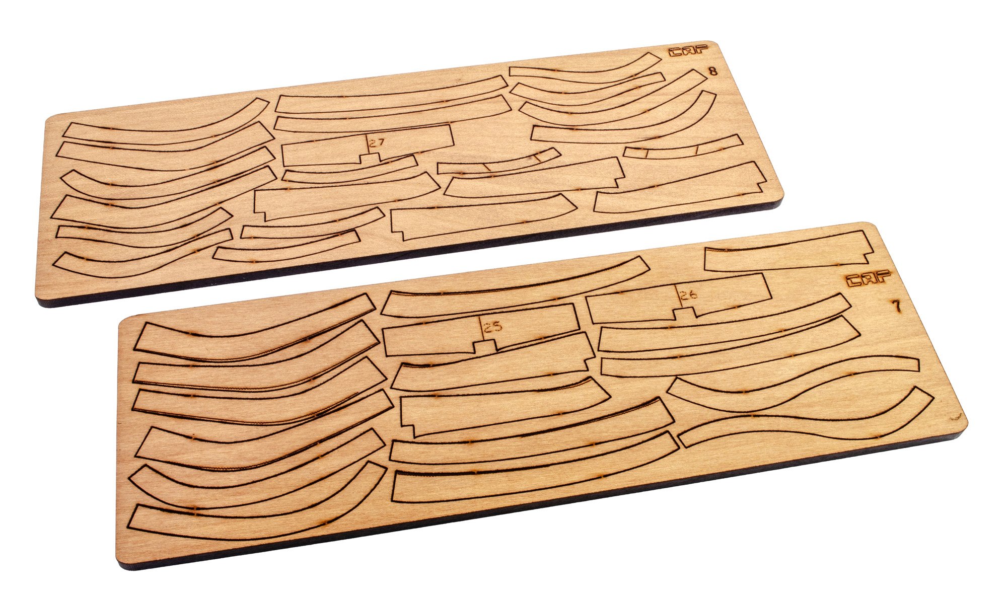
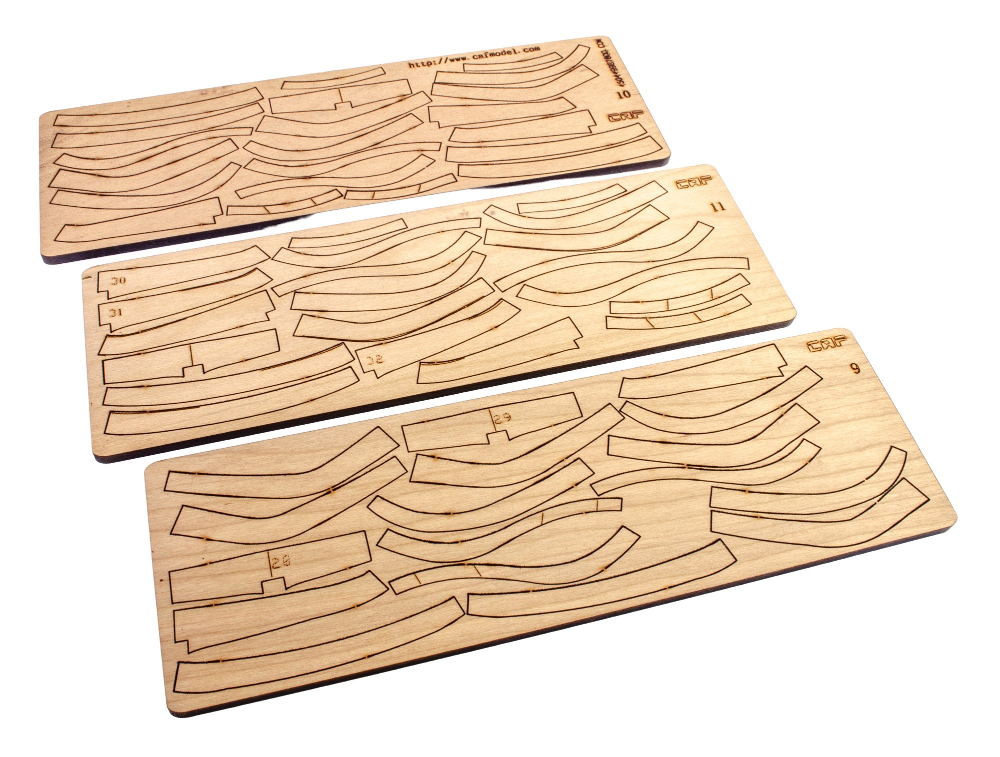
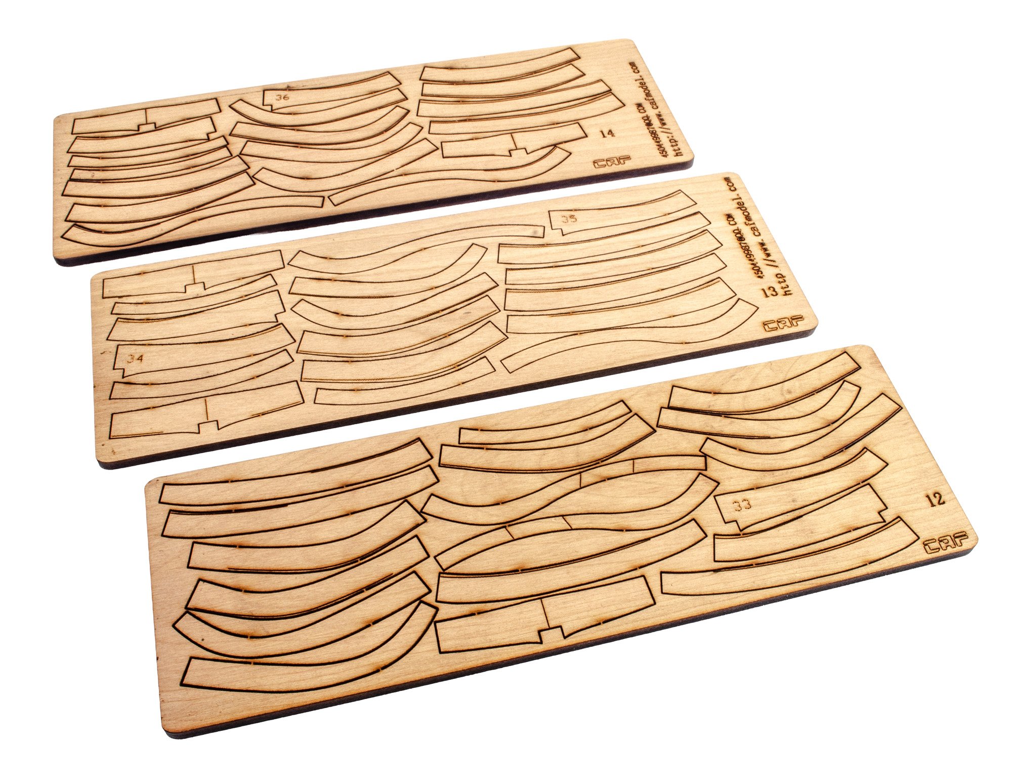
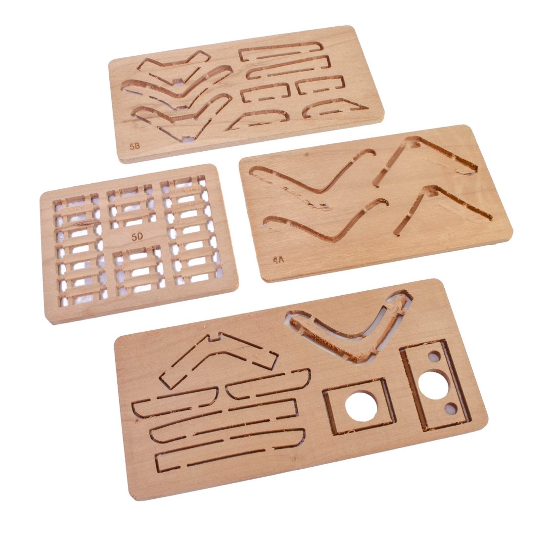
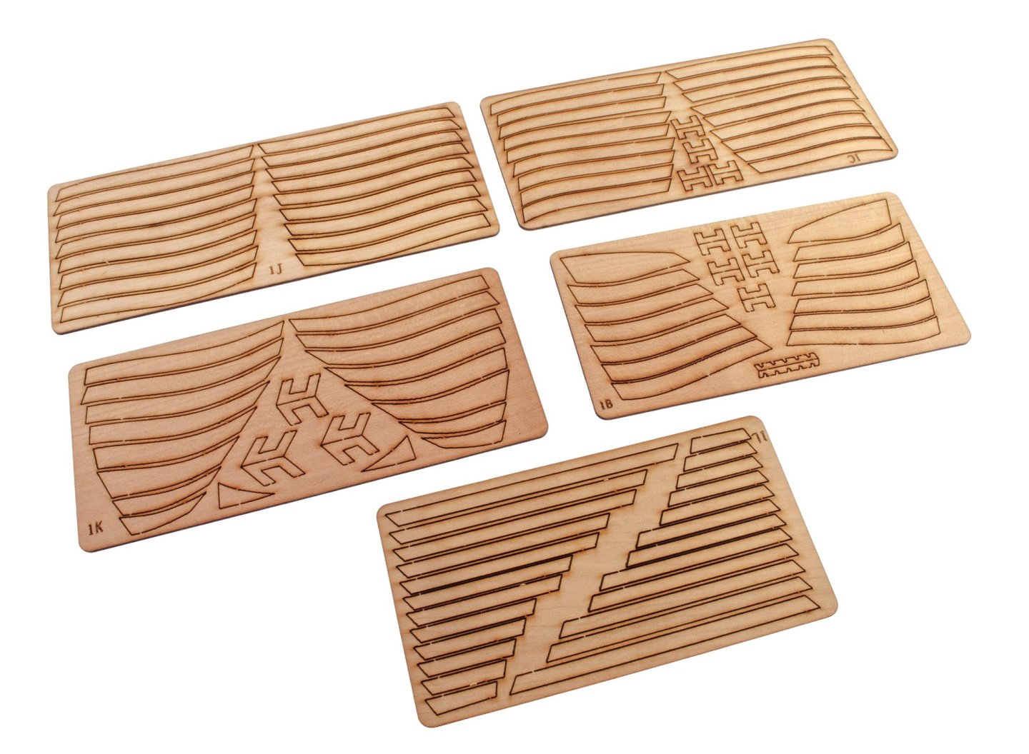
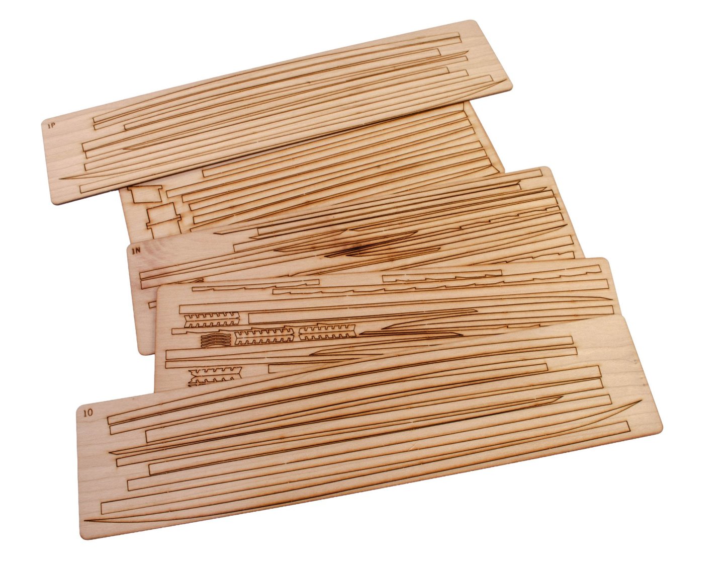
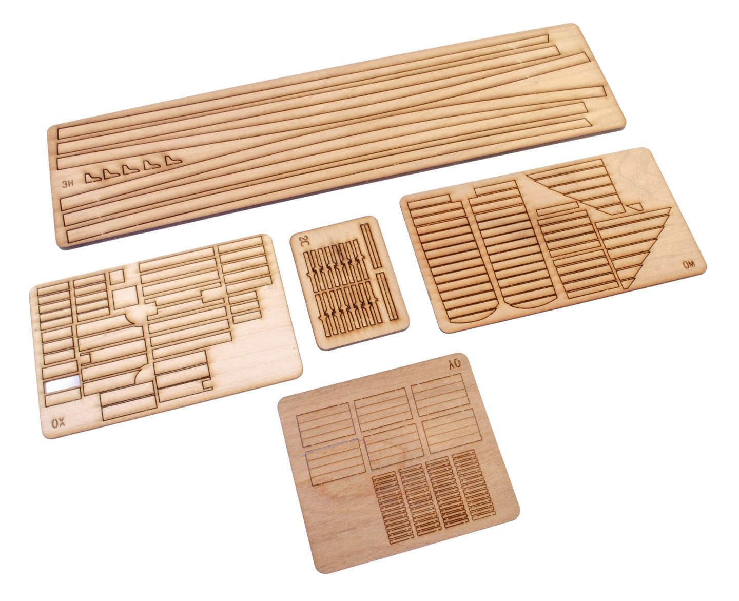
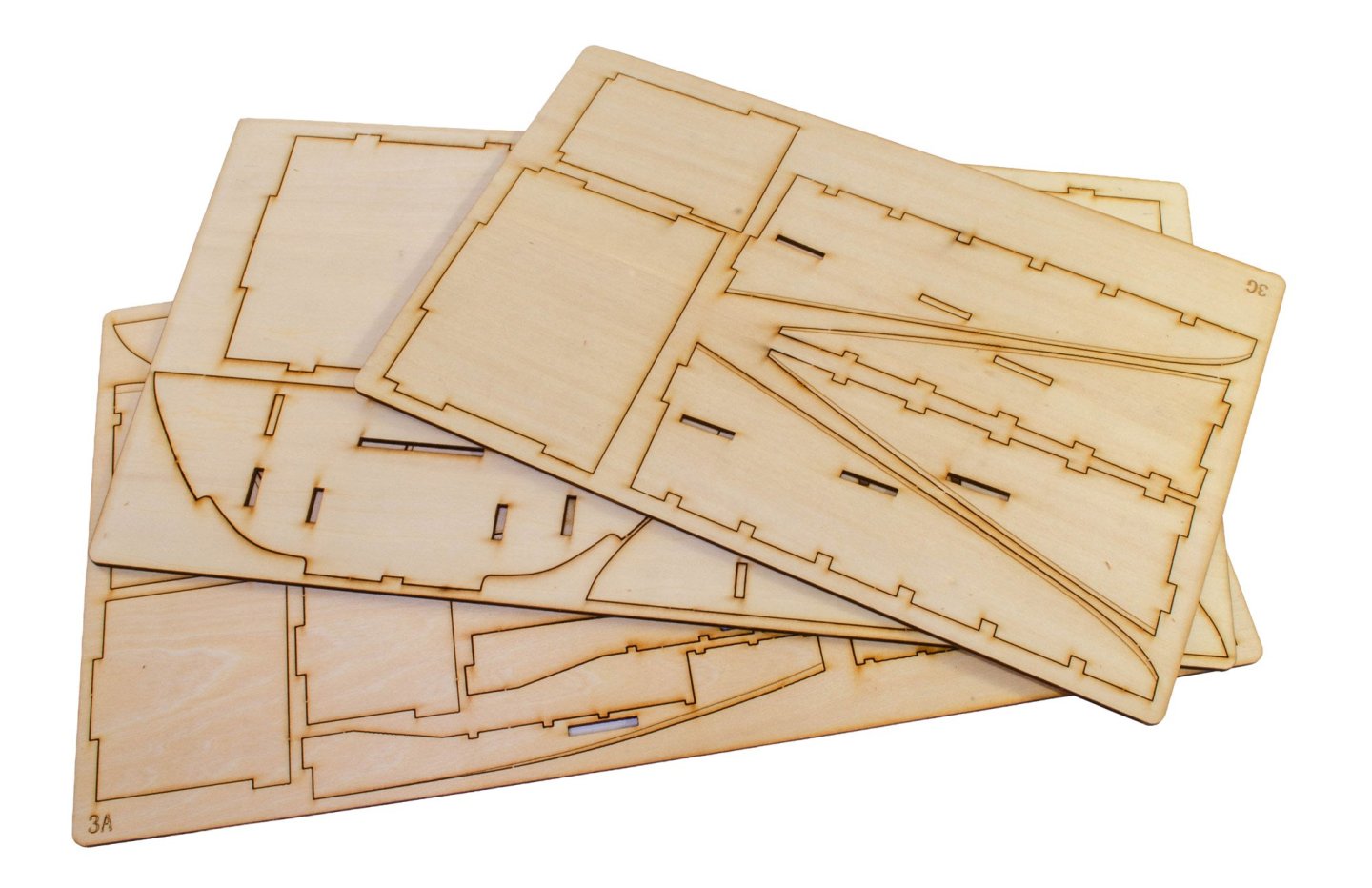
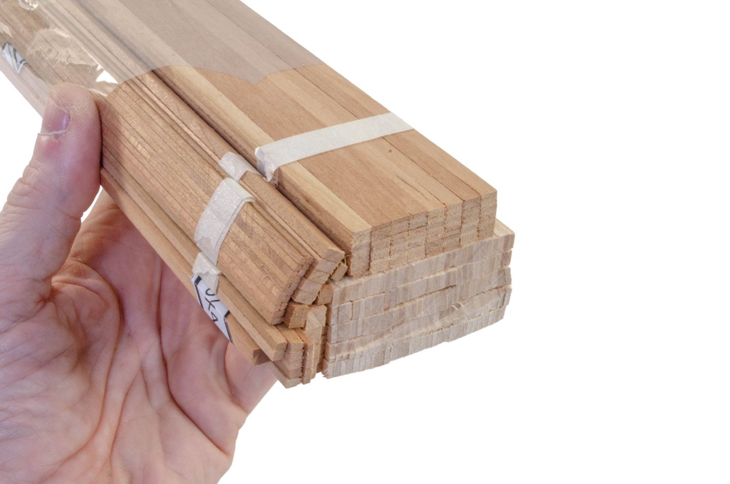
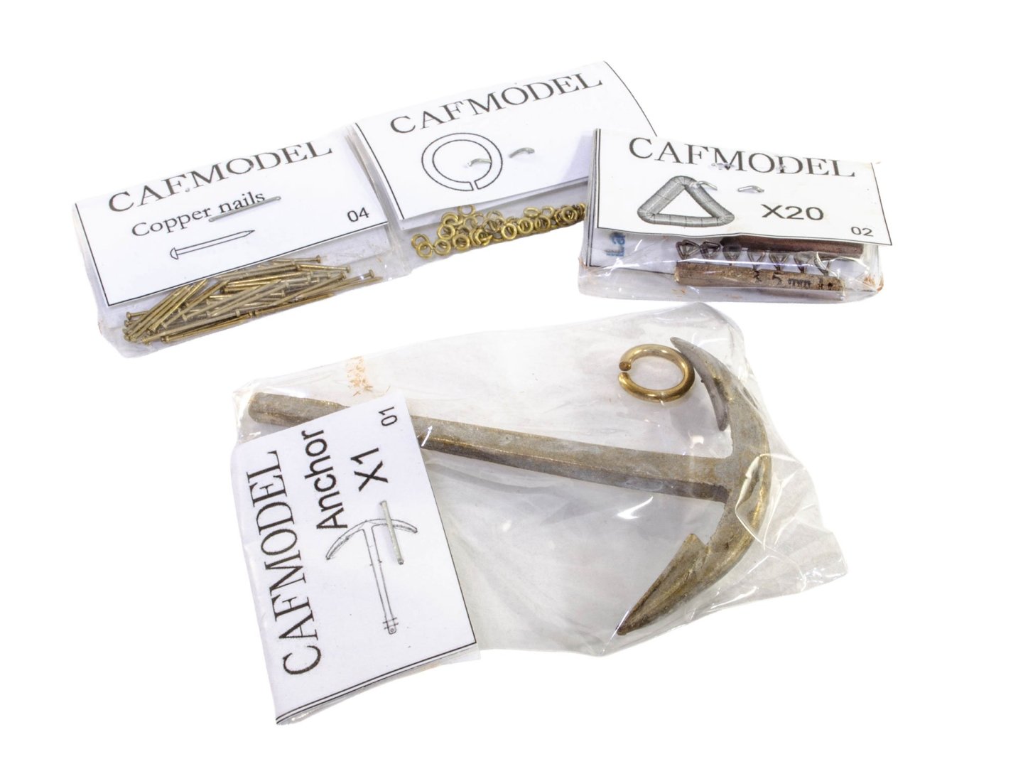
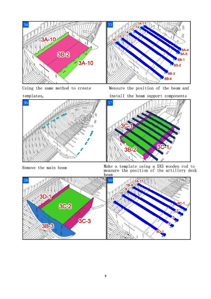
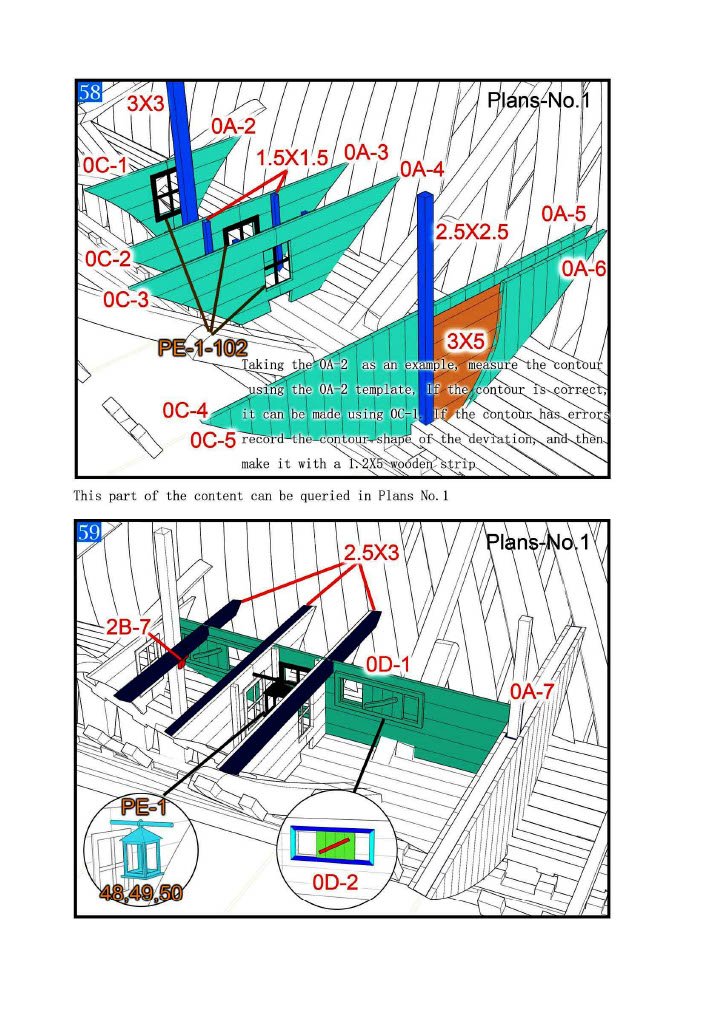
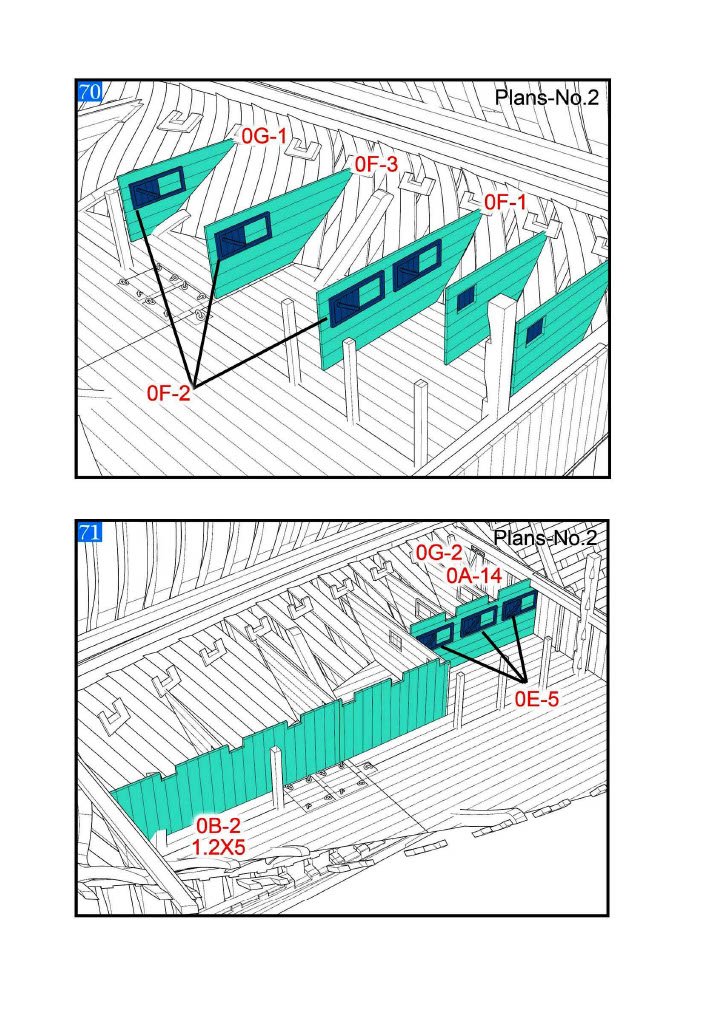
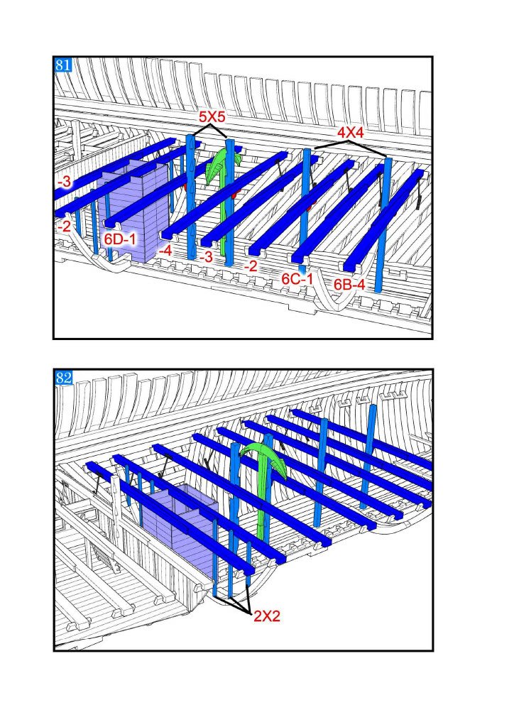
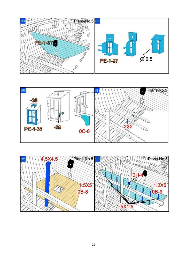
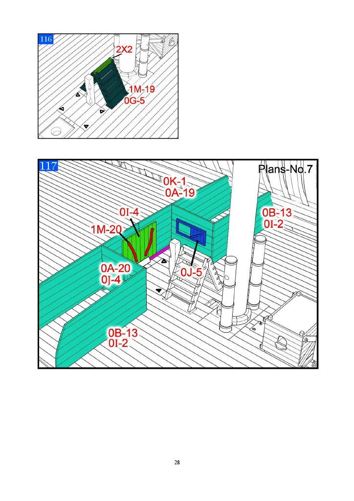
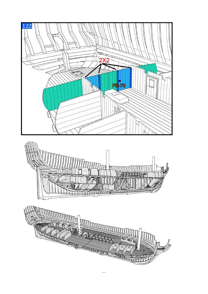
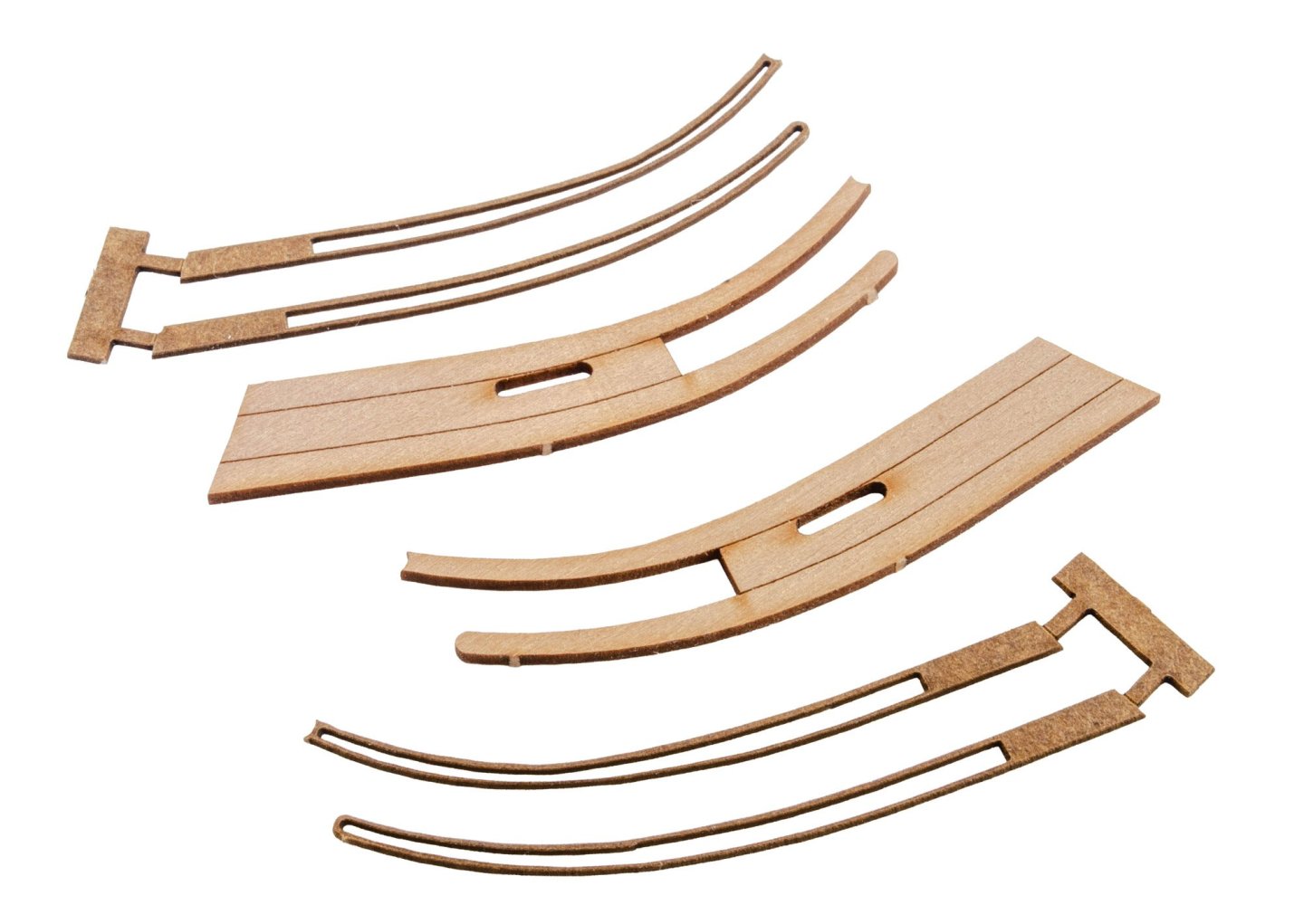
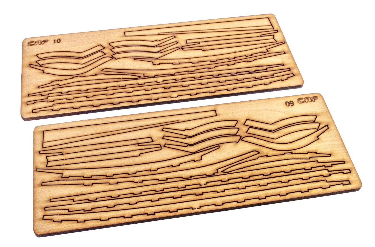
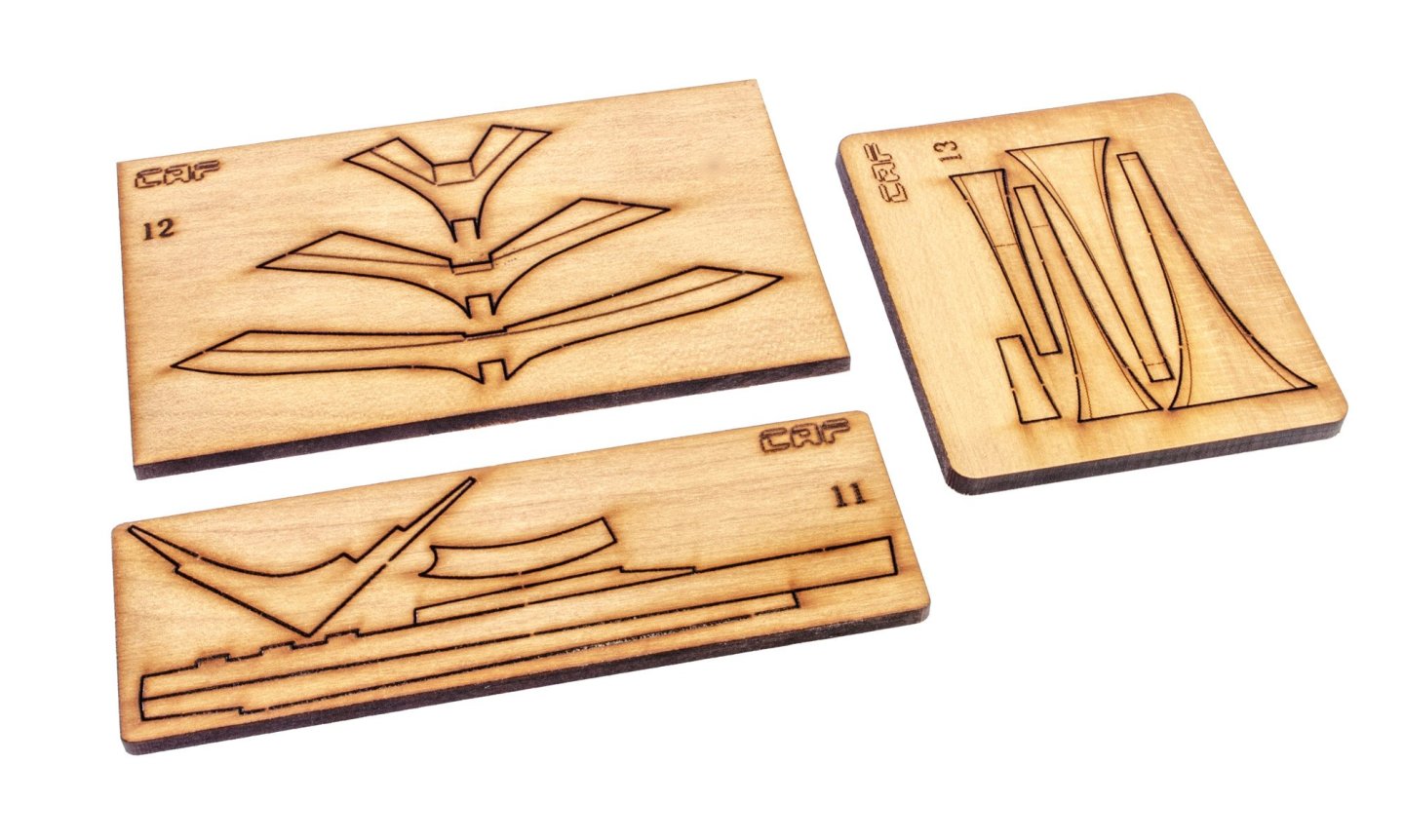
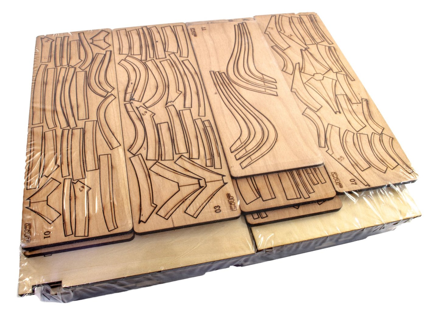
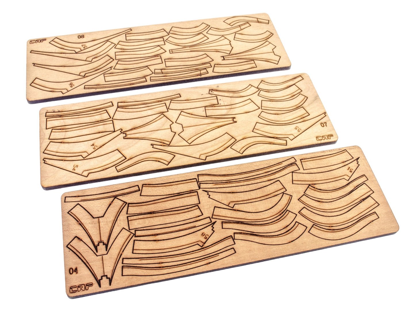
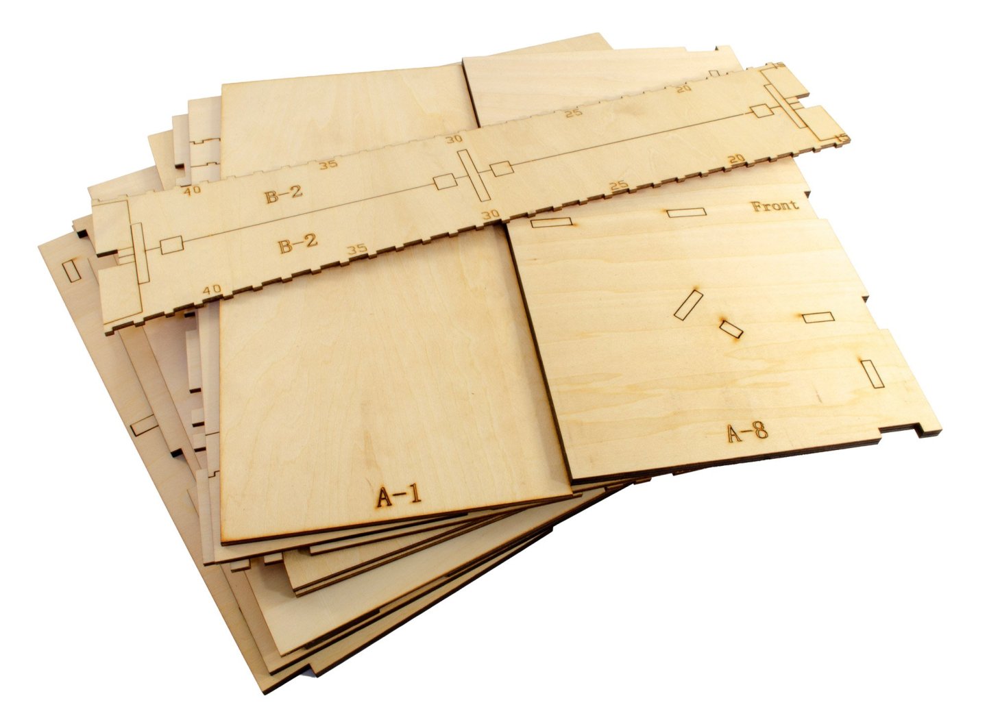
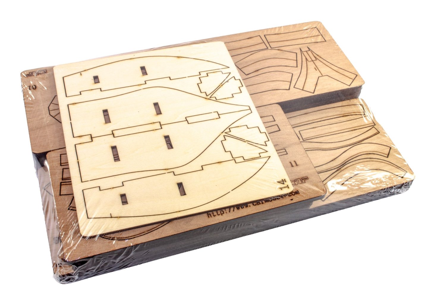
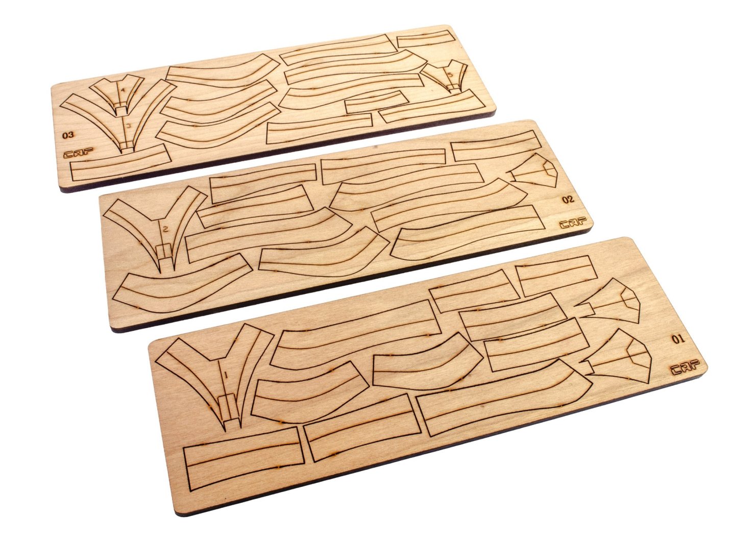
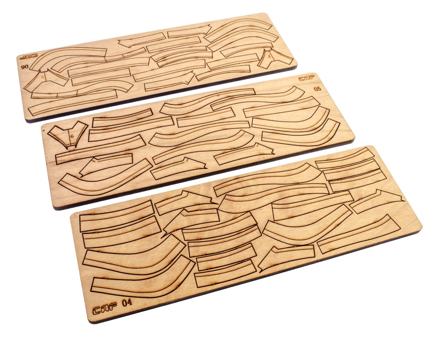
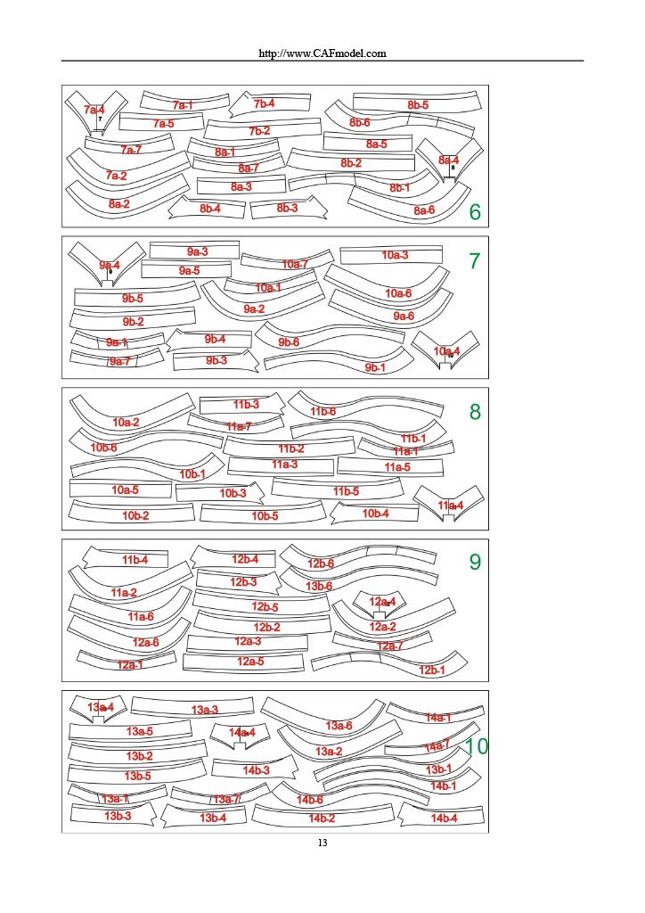
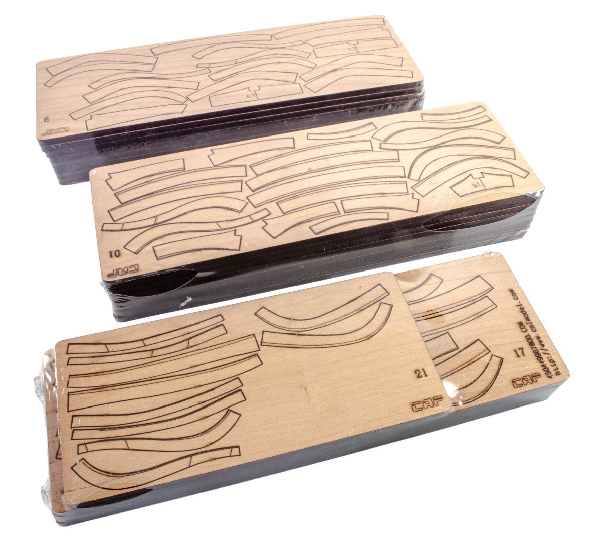
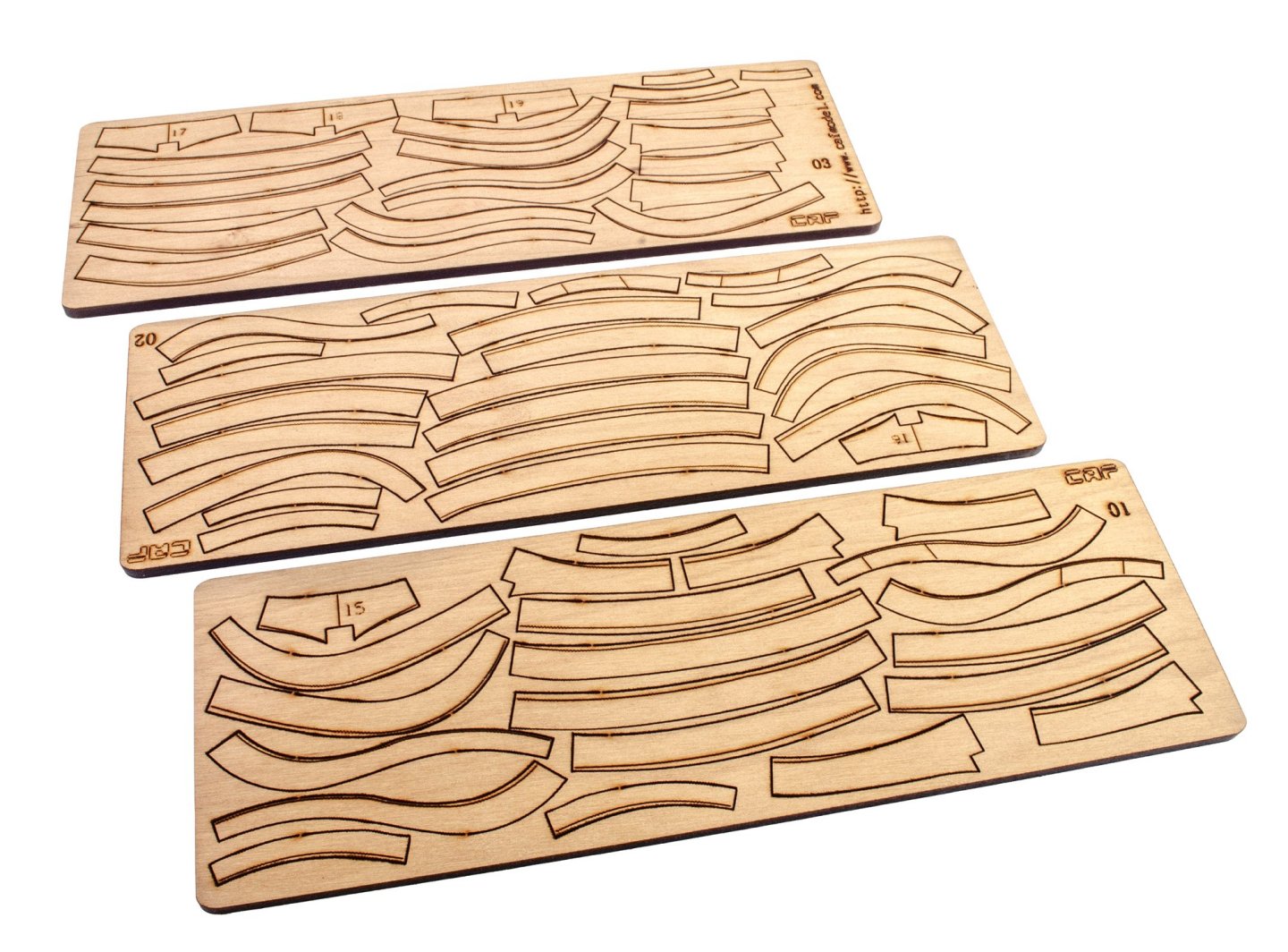
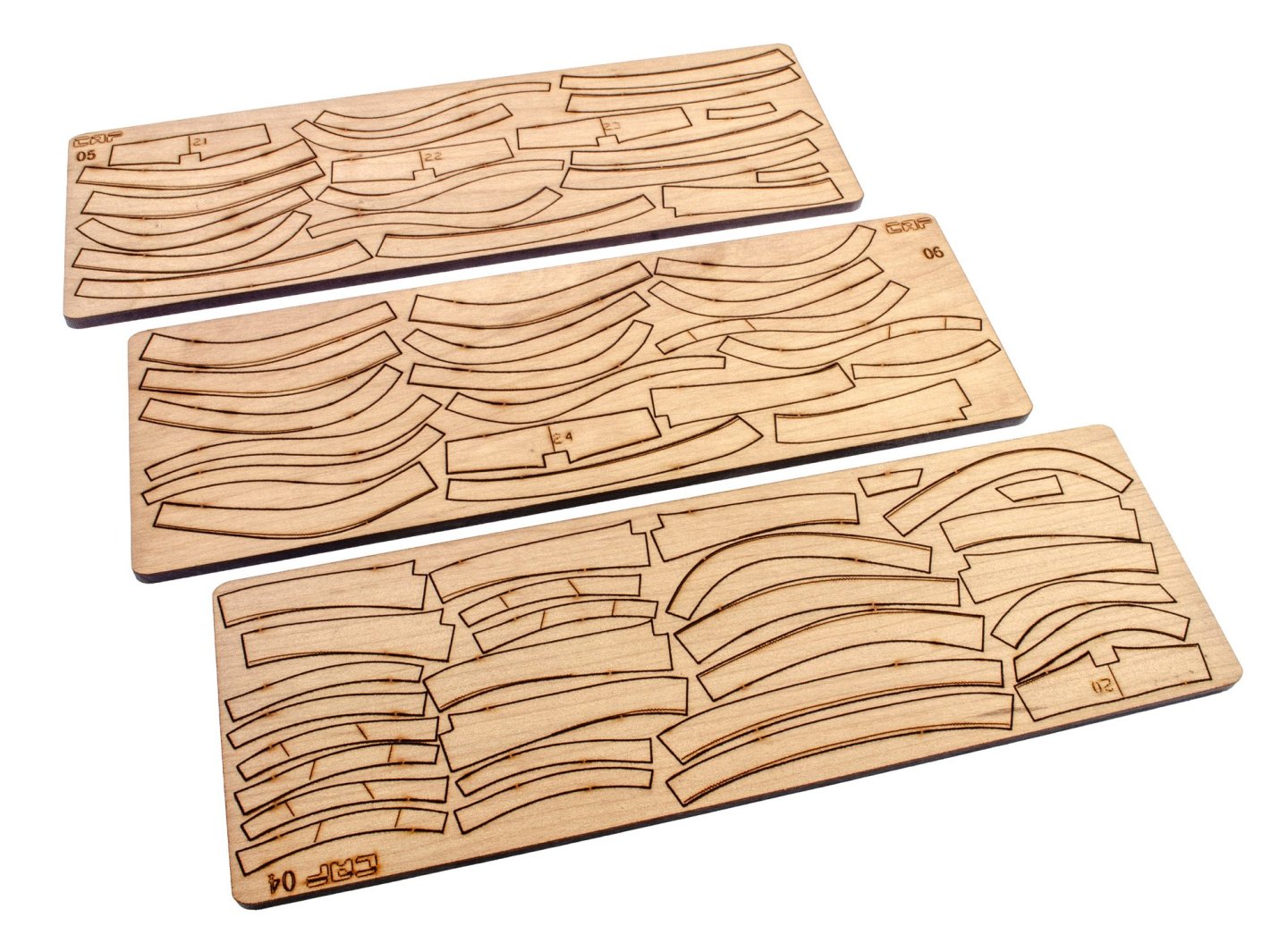
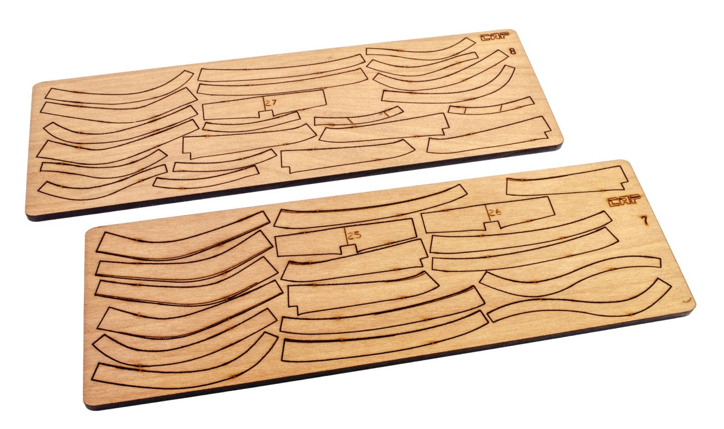
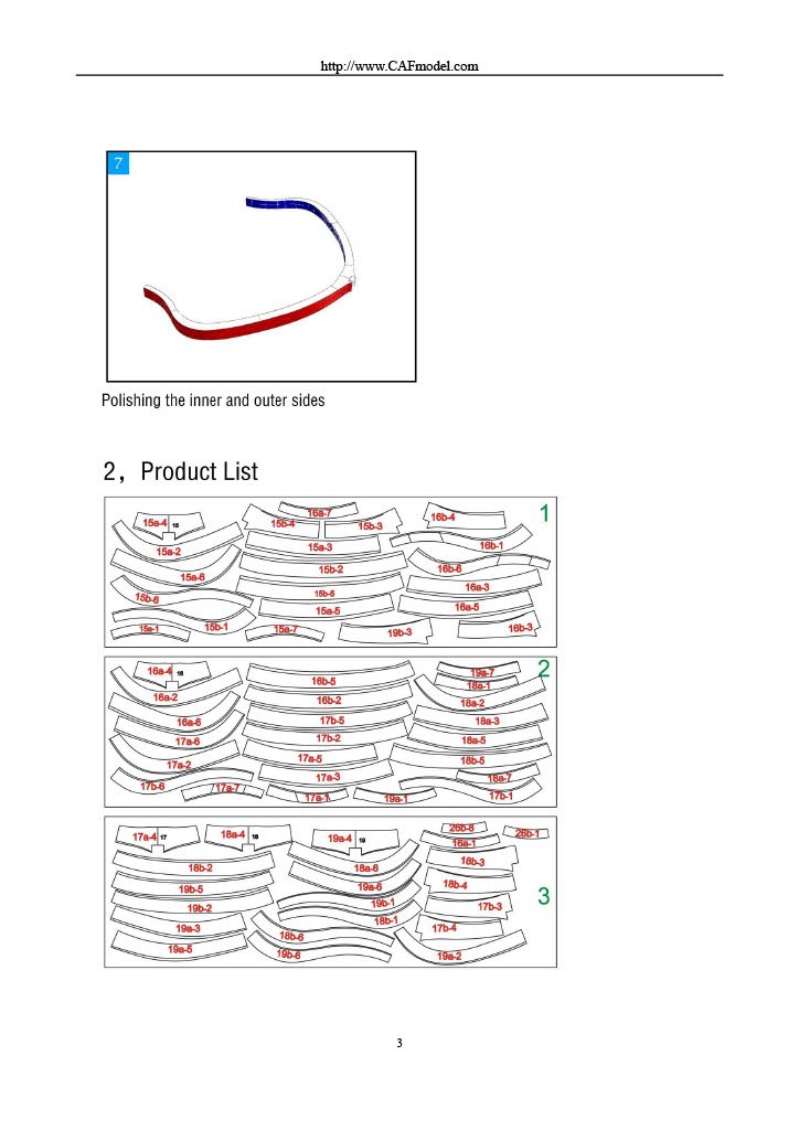
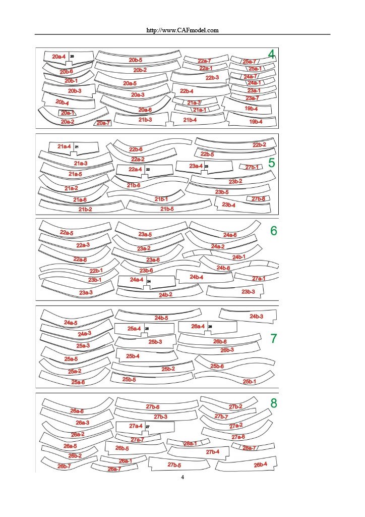
PART 4.5 (Optional) Yes, this box is indeed optional to the final build, but in all fairness, it seems nonsensical not to add it unless you're working to strict budgeting restraints. This set will add all of the main hull internal details, such as cabins, internal bulkhead detail, livestock pens, water pumps...in fact, you name it, and it'll be there. It's certainly a weighty box too and crammed 101% full with an incredible number of sheets, as well as fittings and PE etc. All parts in this pack are packed into a single cellophane wrap, and there are individual stacks of sheet timber, both laser and CNC-cut. These sheets are CNC cut. I did wonder about the levels of debris still attached to them, but the majority of this is attached to the frames and not the parts themselves. I did remove a quantity of this beforehand, so that isn't an issue. A nice, clean cutting bit would definitely be advisable for manufacturing though. This pack contains around 31 sheets of laser-cut cherry parts, and a further 9 sheets of plywood for creating the various internal shapes within the hull structure. All laser work is nicely cut, and with minimal rear scorching. As a matter of course, I'd routinely use a sanding mouse with a fine grit to finish off the rear of all sheets so that none of that wood colour shows any discolouration. Quite a large pack of cellophane-wrapped timber is included in this set, all very uniform in colour, nicely cut with no bad edges, and also marked up for identification. Two sections of dowel are also supplied, as is a roll of brass wore, in a CAF wooden spindle. Various packets show rope, pump tubes, a resin jig for building poultry shed, eyelets, nails, internal anchor (stowage), and what looks like hatch lifting loops which are made from cast metal. A large, single sheet of photo-etch is supplied. Here you will find parts for window frames, pump filter ends, lanterns, door hinges etc. PE quality is excellent with only small gates to remove each part. It took about 15 minutes to finally get all of the parts back into the box, along with the manual etc, and that lid is still bulging. Instructions The manual for this set is 46 pages in A4 format, clearly printed, with of those pages being part maps alone. If you want to have a preview of this manual, then it's on the CAF website along with the other kit chapters. Here are just a few selected pages. In the next week or so, I'll show the penultimate pack #5.


- 16 replies
-
- 20
-
-

-
- cafmodel
- la renommee
- (and 1 more)
-
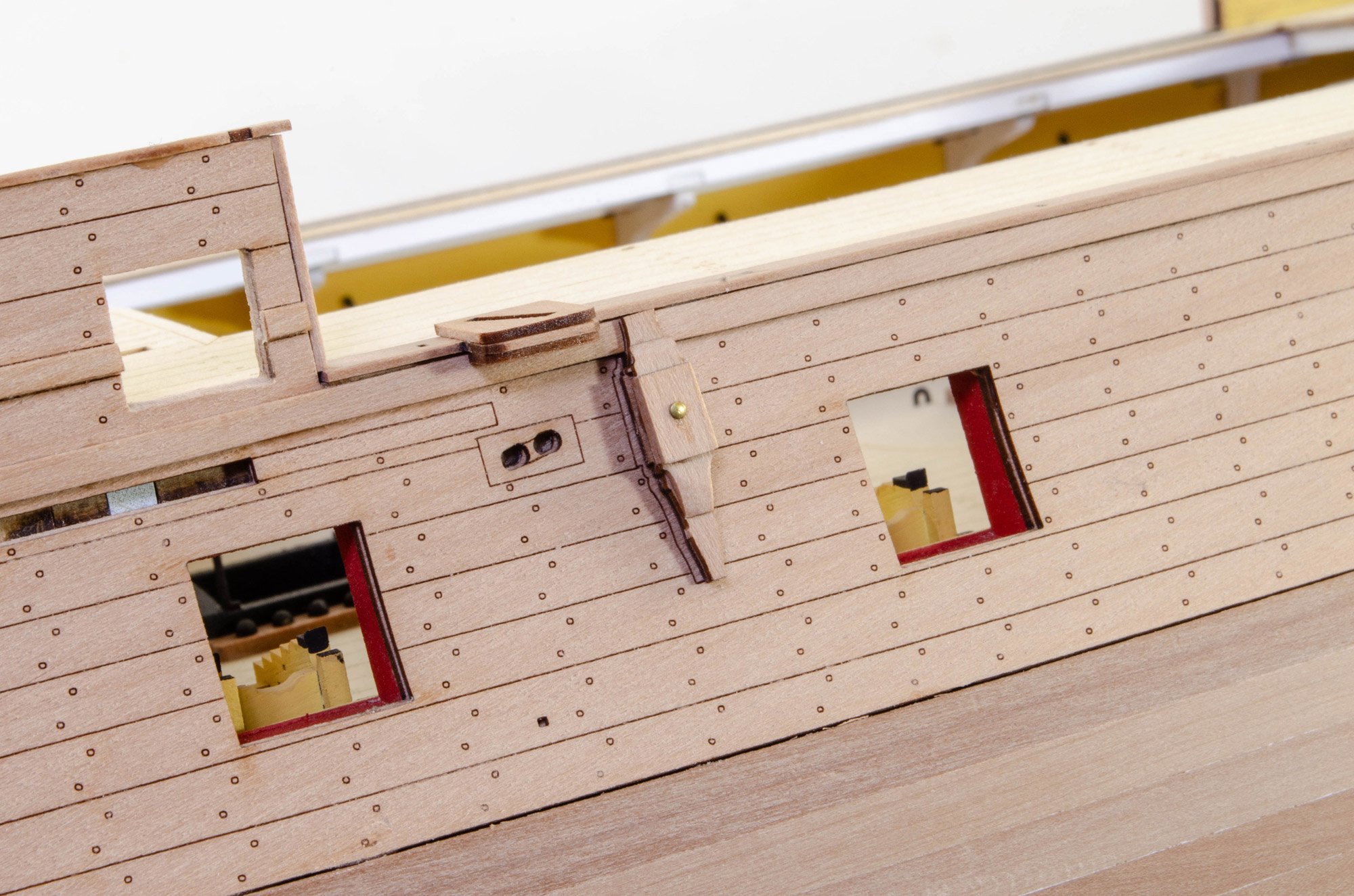
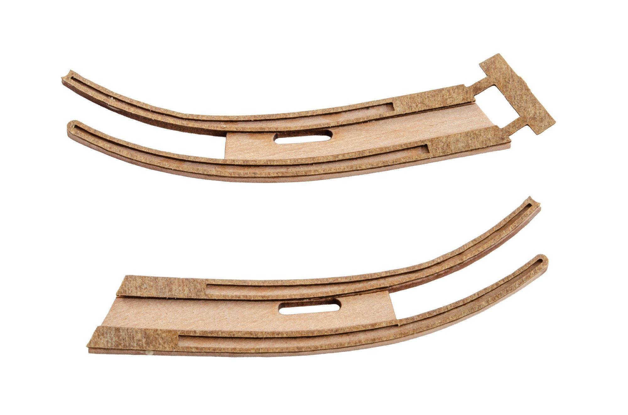
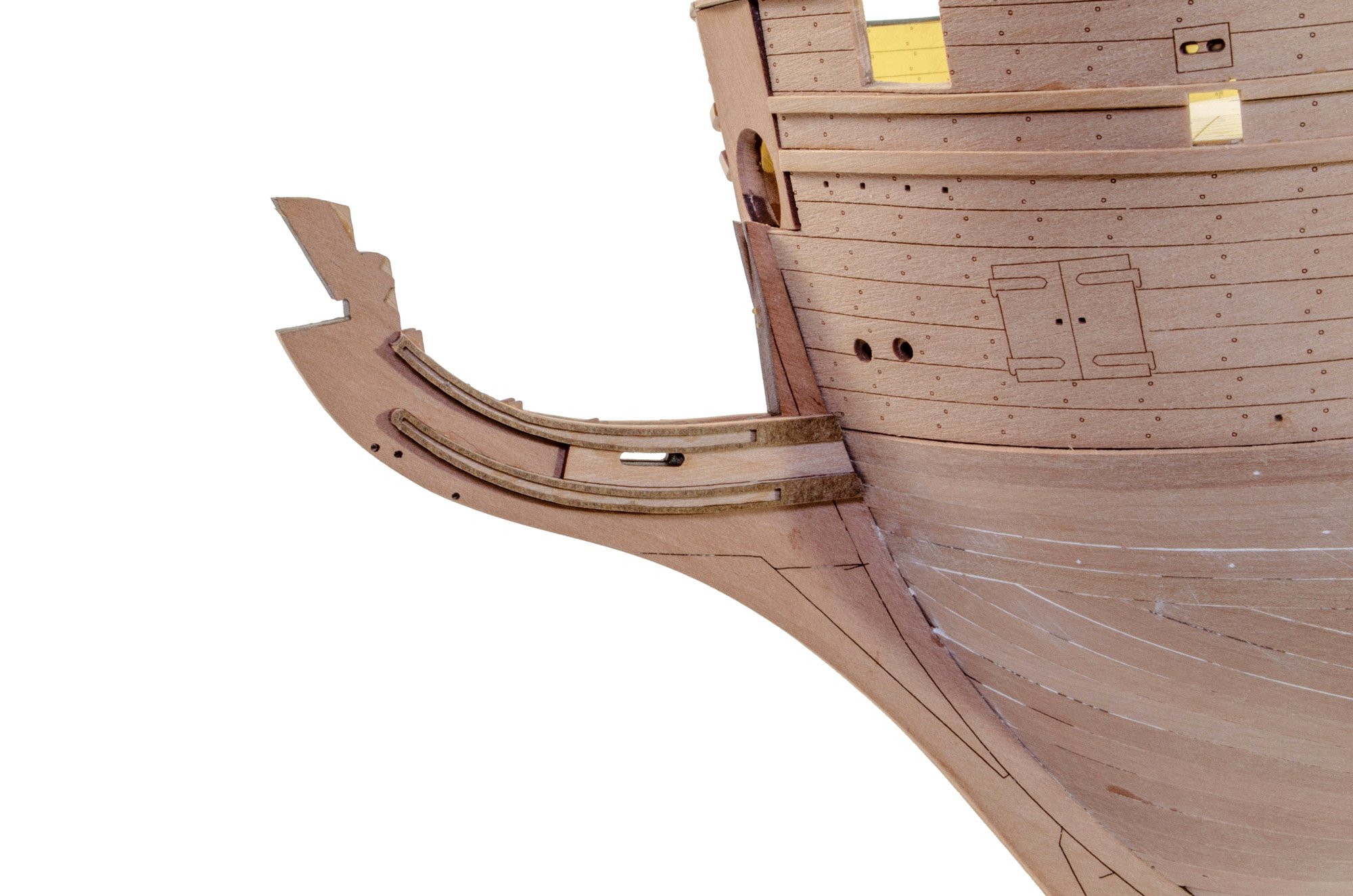
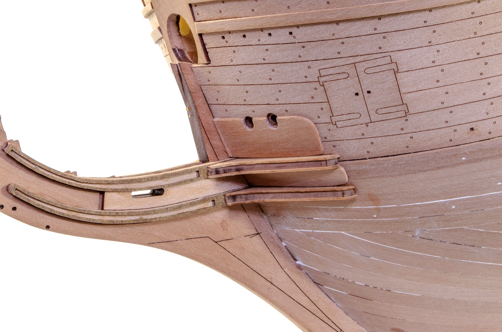
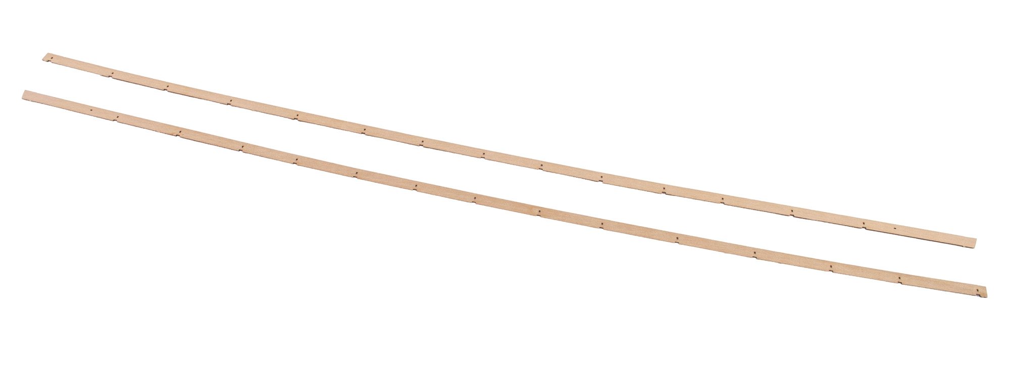
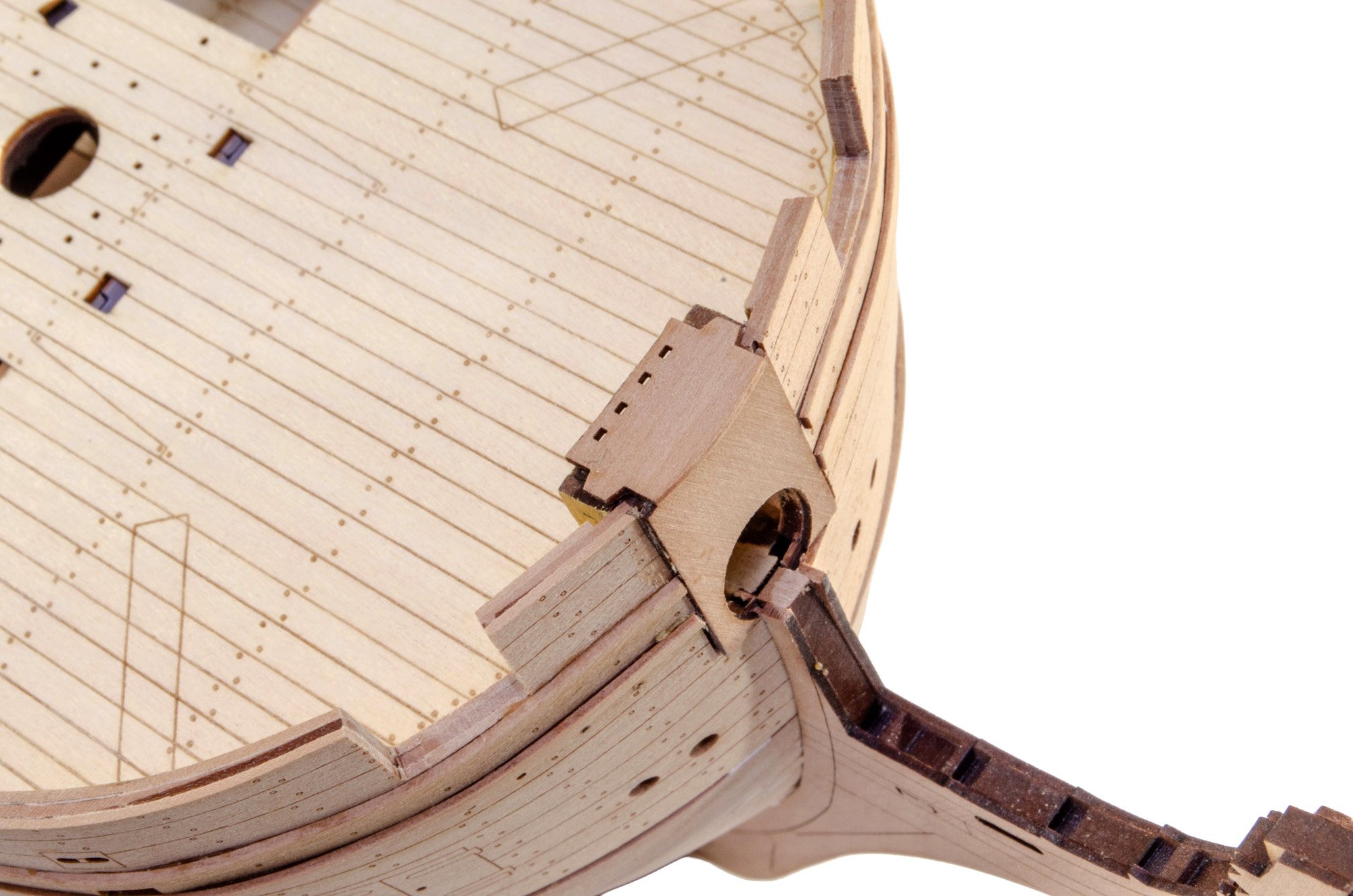
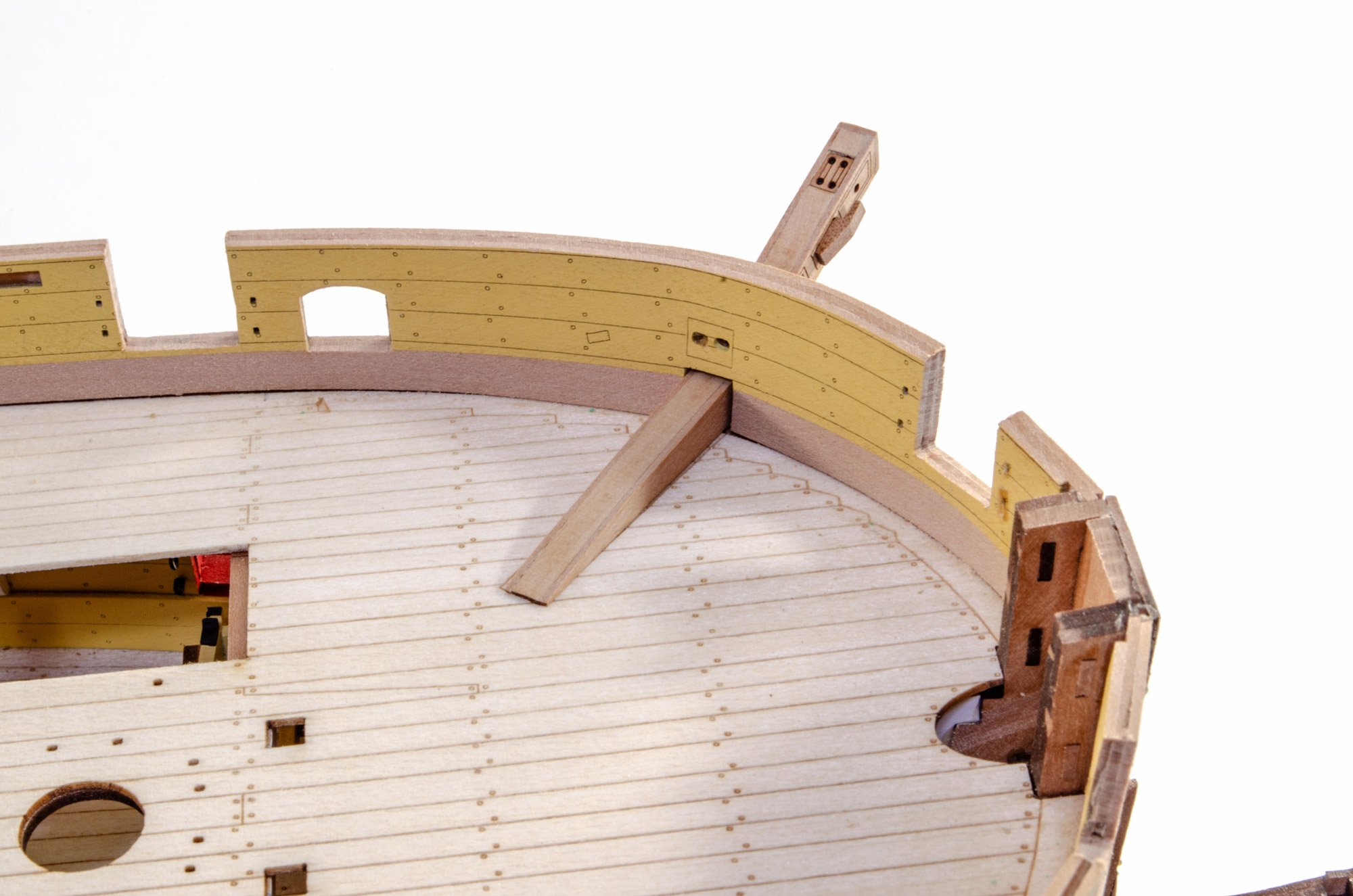
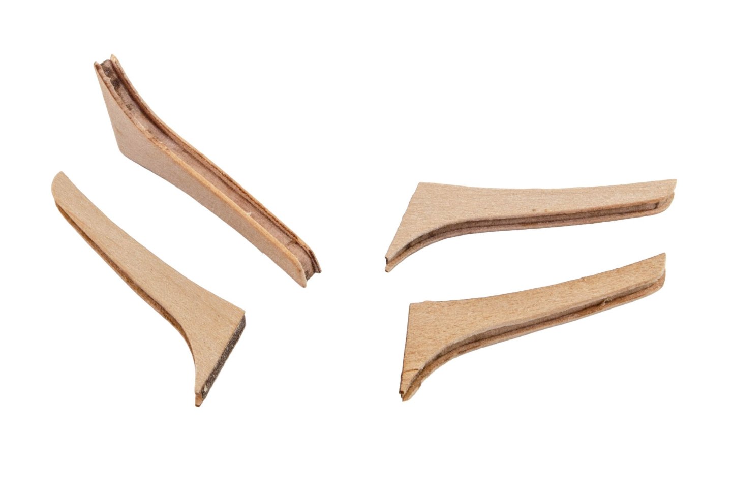
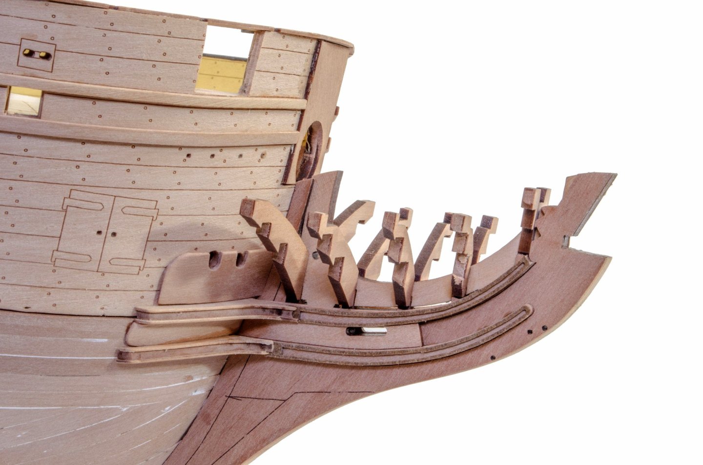
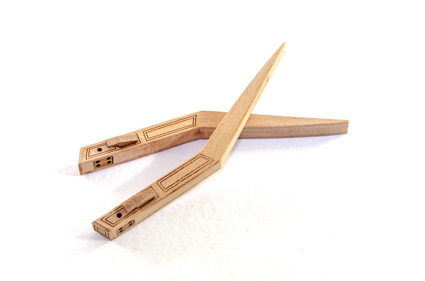
Last update before paint. At the moment, I've been finalising some external details before I can finally mask up the hull and start to apply the ochre colour and do any last minute filling that might be necessary. Here are the completed chesstrees. The deck beam edges are. now carefully hidden with decorative edgings The prow hair decorations are included as both pear and PolyBak. As this model will be painted, I opted to use the latter parts. Here you can see how they are fitted. Then onto the cheeks, bolsters, and V frames for the final details. The latter assembly isn't glued to the hull at this stage.


- 145 replies
-
- 27
-
-
-
As soon as they show an interest and have a little dexterity. That goes for any type of modelling. I built my first model when I was 7 or 8, using a craft knife and supervision. By the time I was 10yrs, I was wielding a surgical knife and have honed that skill ever since.
-
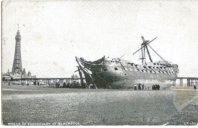
Absolutely! One of Nelson's flagships, and also one of only two of his ships ever captured on film; the other being Victory. Foudroyant was wrecked only about 30 miles from me.
-
Nothing goes in that gap. It's purely decorative. I do need to add the shingles to the roof areas though.
-
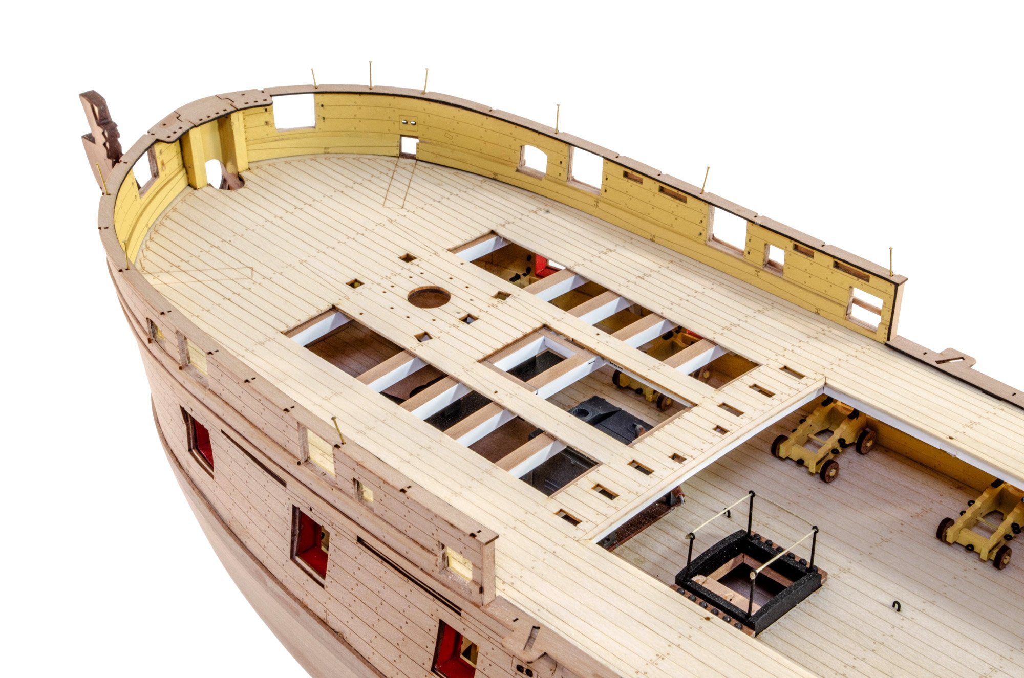
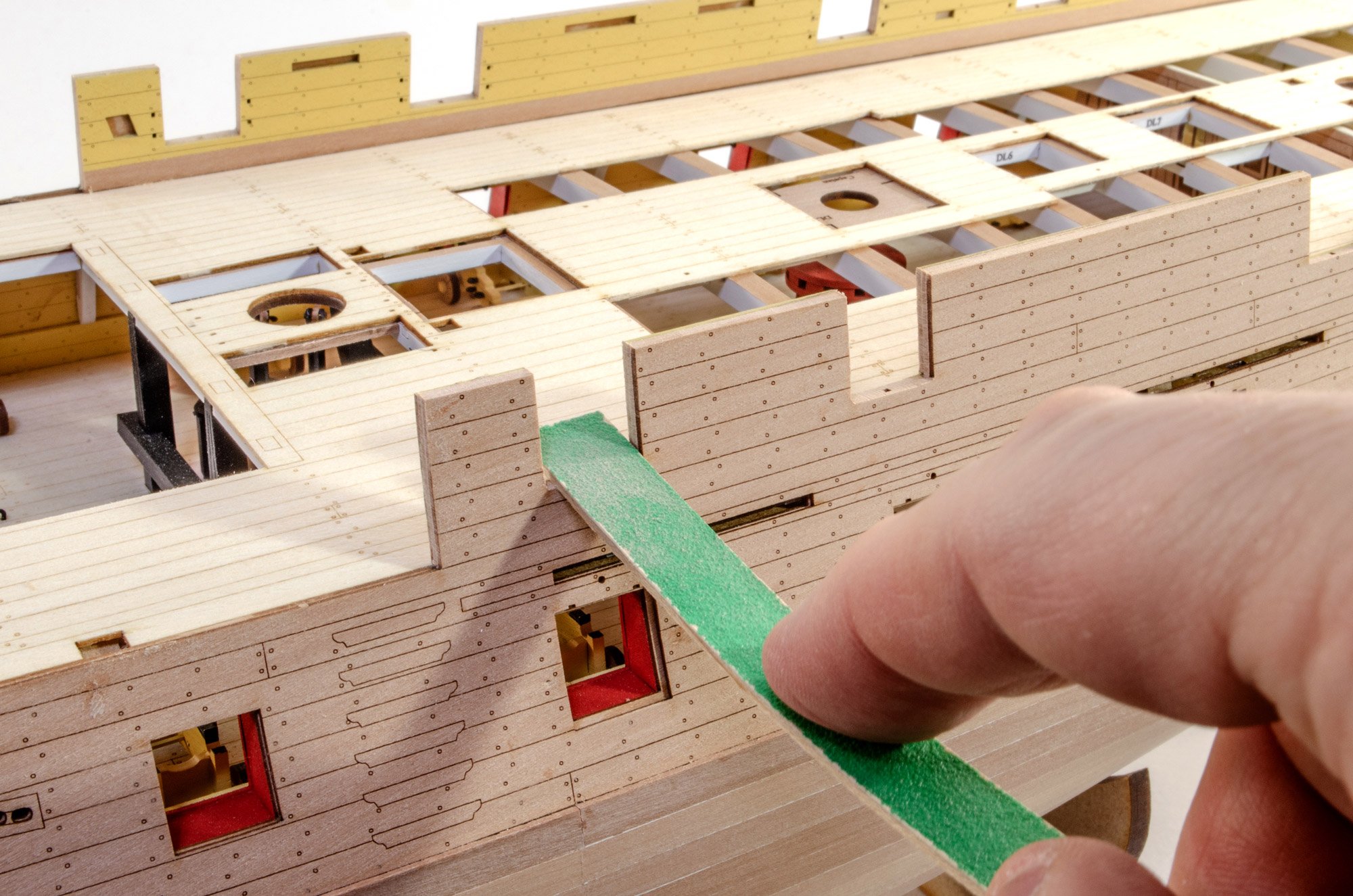
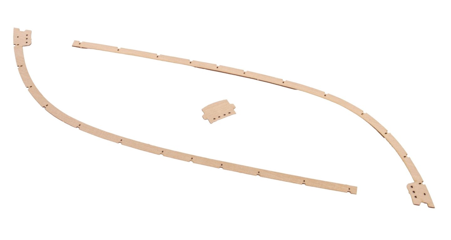
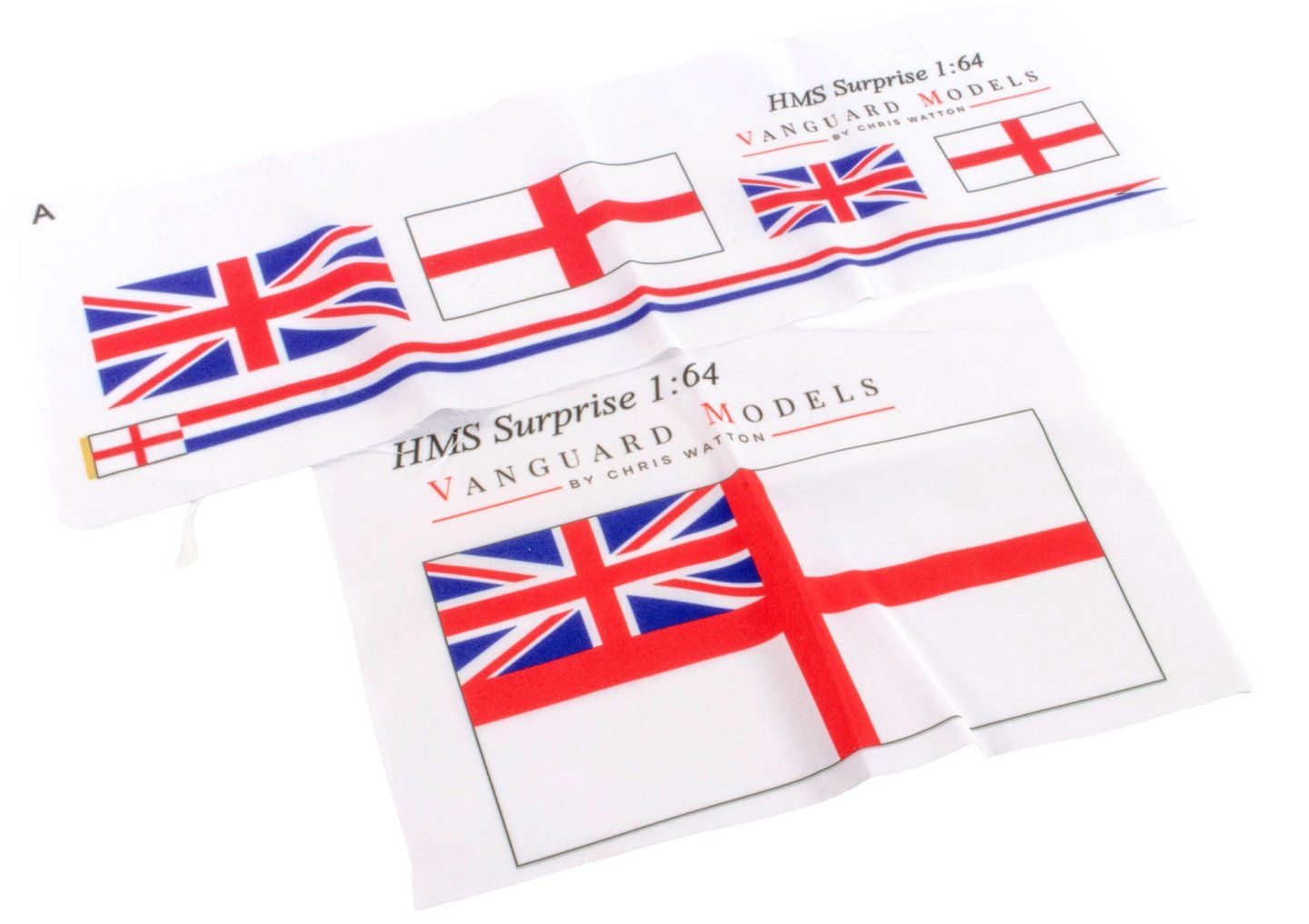
As promised. Recent work has been fitting various gunwales etc. It's real nice to see the finishing caps to the bulwarks, and the laminated areas finally disappear. These are the waist gunwales. Note that I have painted the inner edges of gunwales etc. in black. This just means I don't have the scary job later on, when the main colour is added to the hull. These parts are the verticals for the ends of the bulwarks, tidying off those areas. When dry, they are flushed with the top of the bulwarks. The forecastle bulwarks have been tackled slightly differently with Surprise. To begin, there is a section which is glued in right at the front. This means that the side pieces are now easier to manipulate around any inconsistencies that the modeller might've built into their specific model. Now the quarterdeck gunwales are fitted. I should've posted this photo a while ago. This is the flag set for Surprise. The quality is excellent....no stiffness in the material. It already hangs far more naturally than previous flags. These weren't a cheap addition, but thought to be worthwhile.


- 145 replies
-
- 37
-
-
Small update coming tomorrow.
-
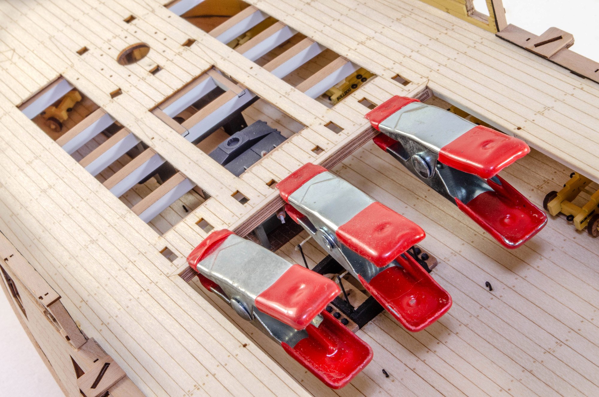
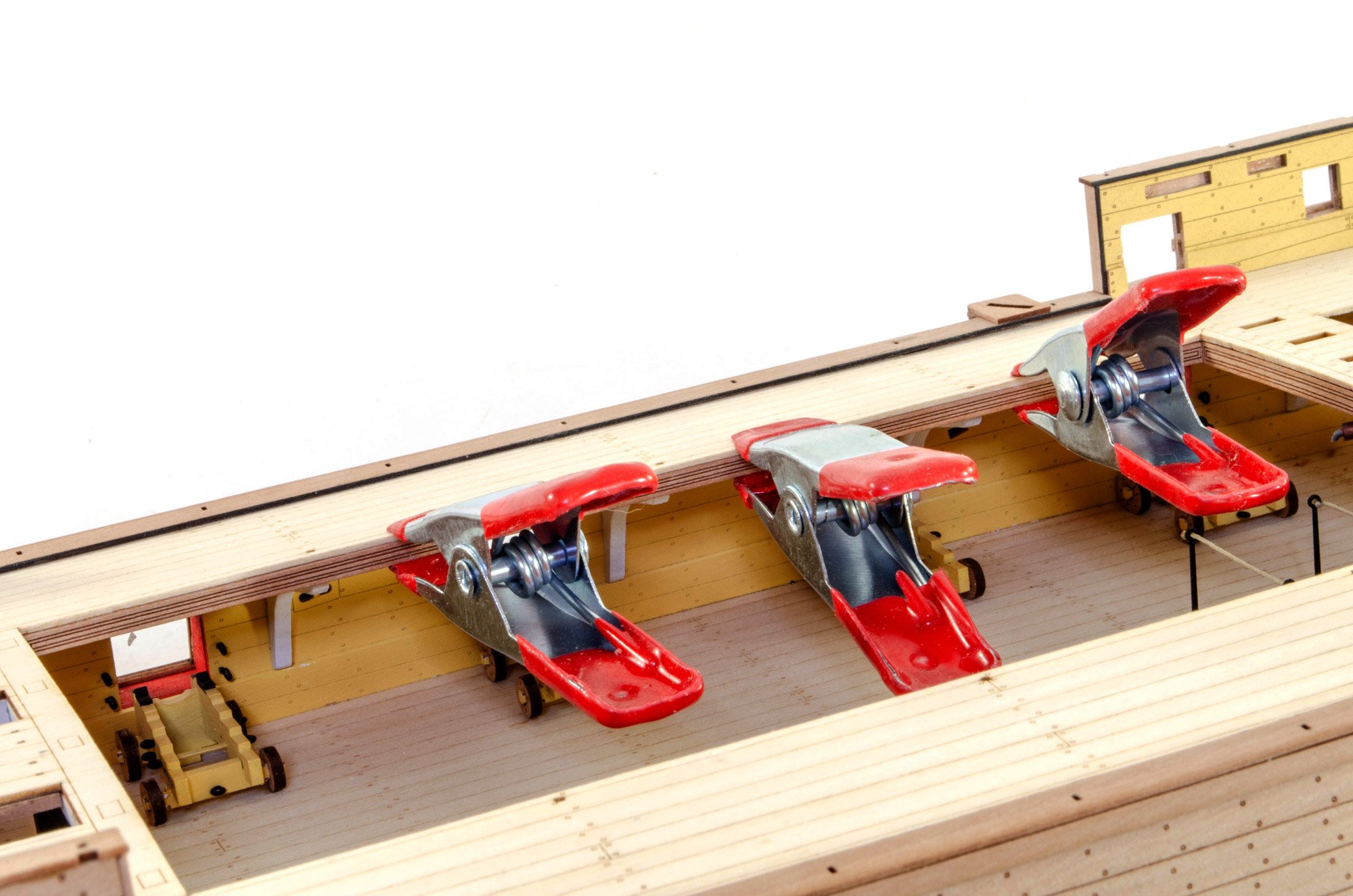
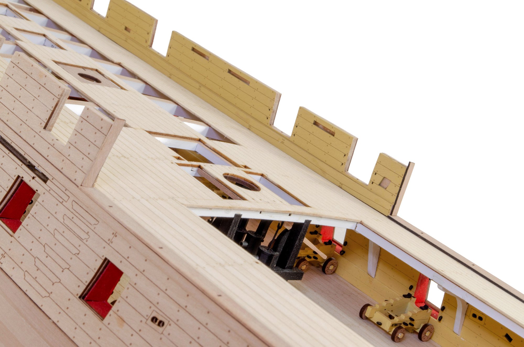
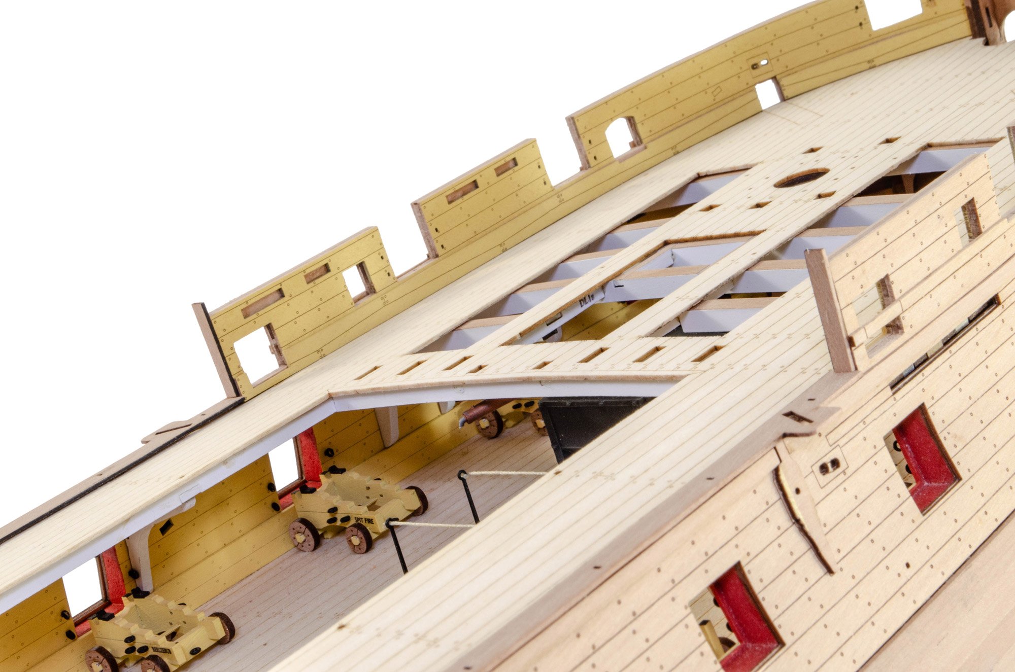
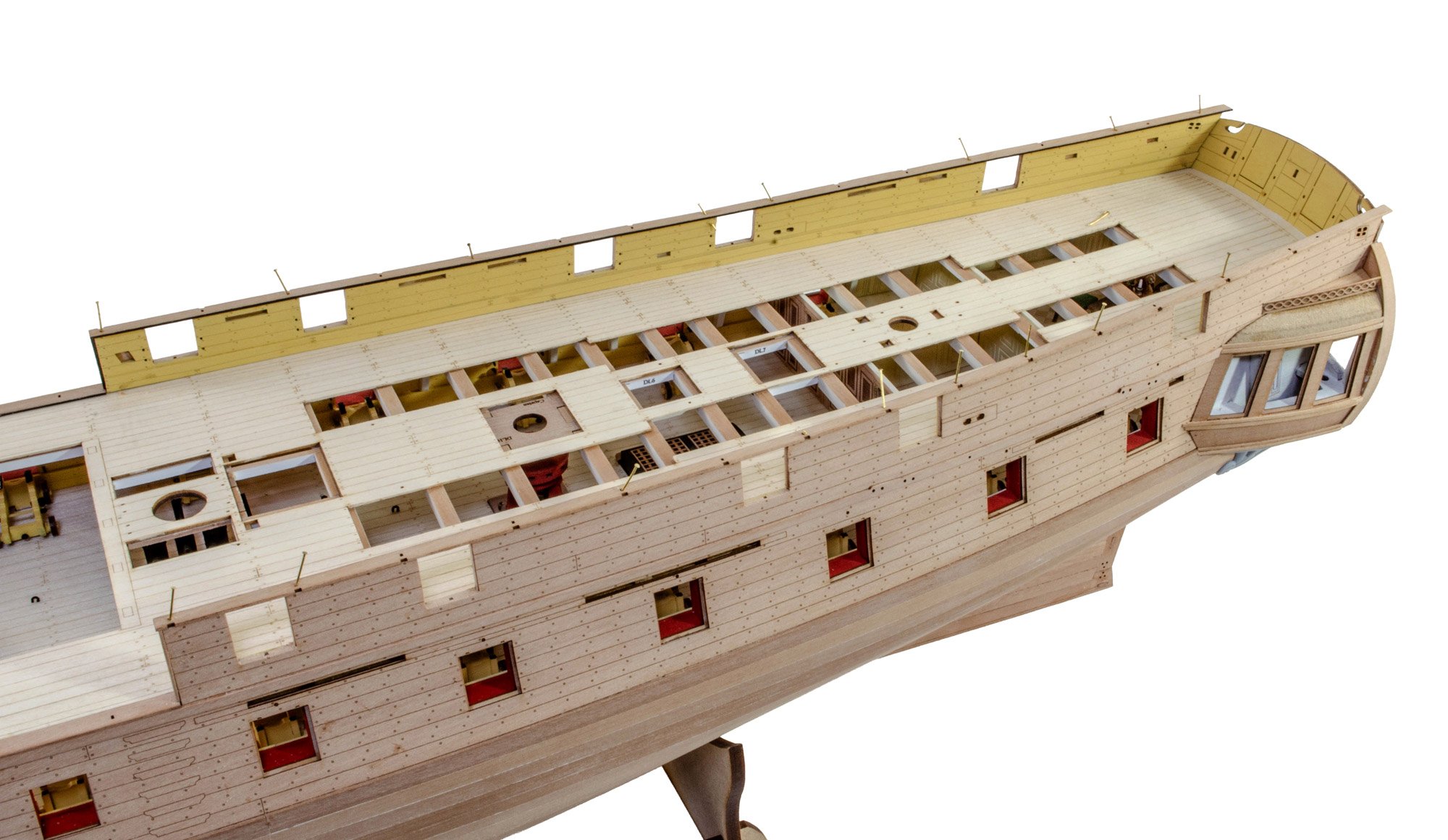
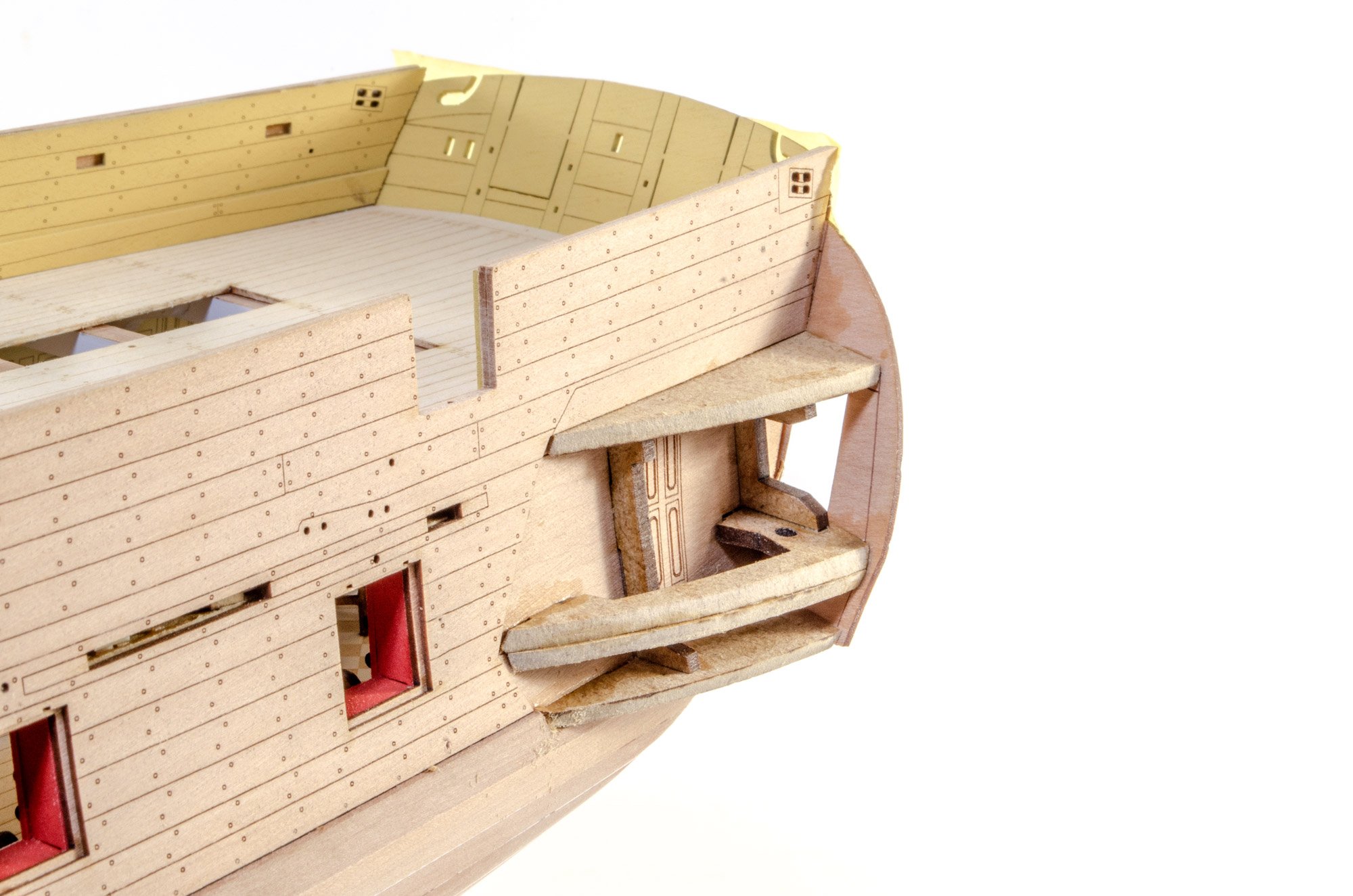
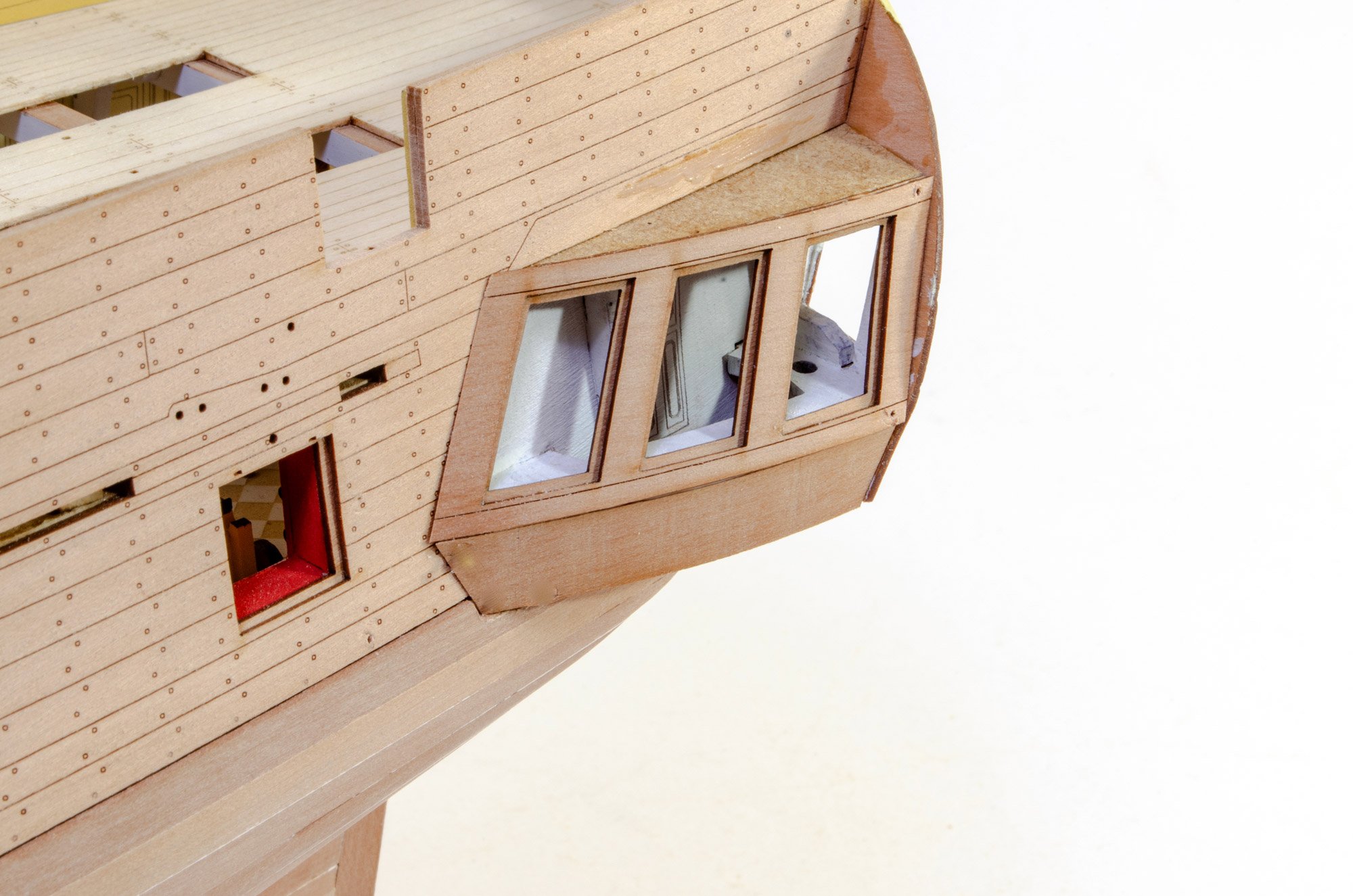
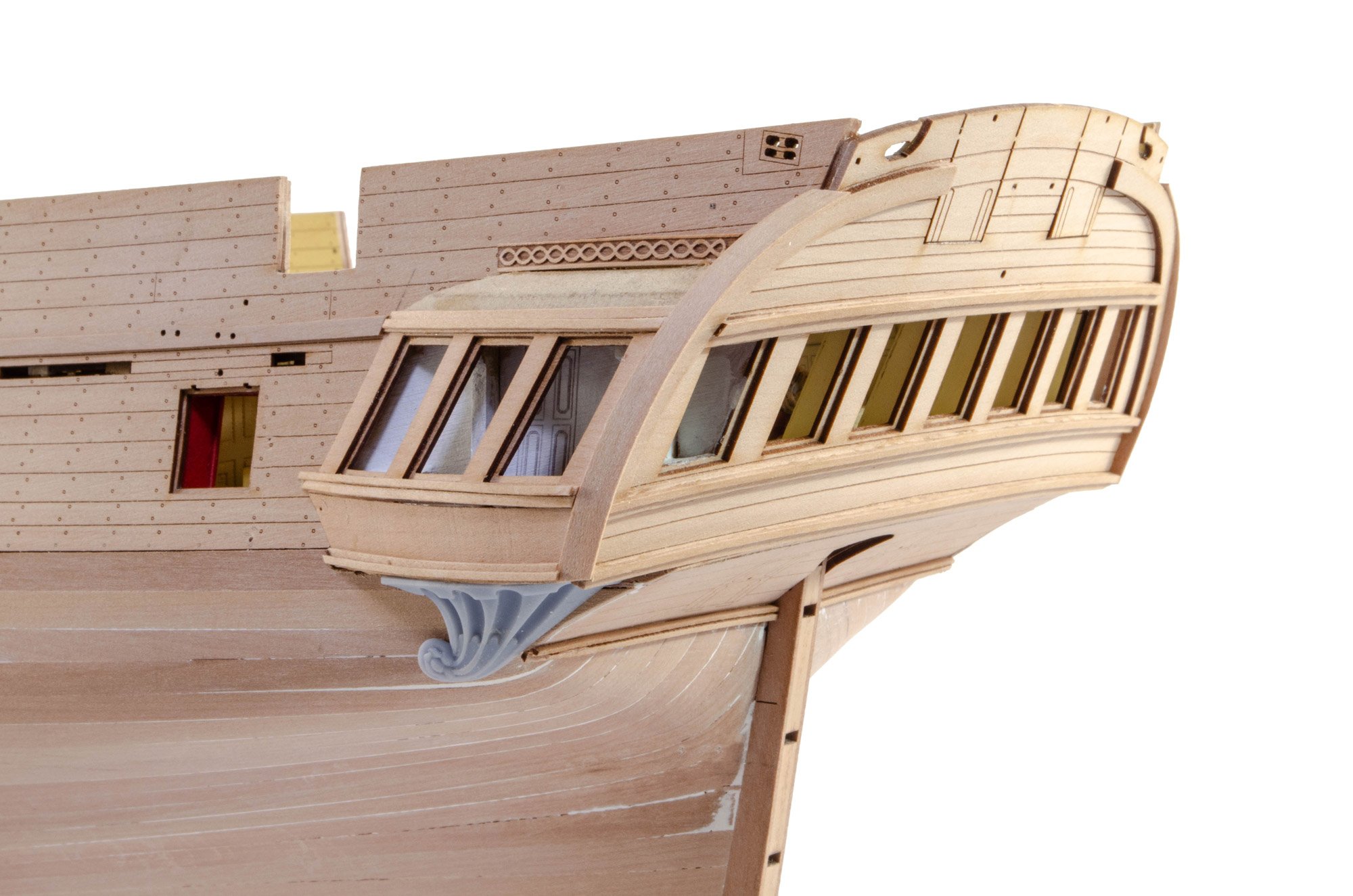
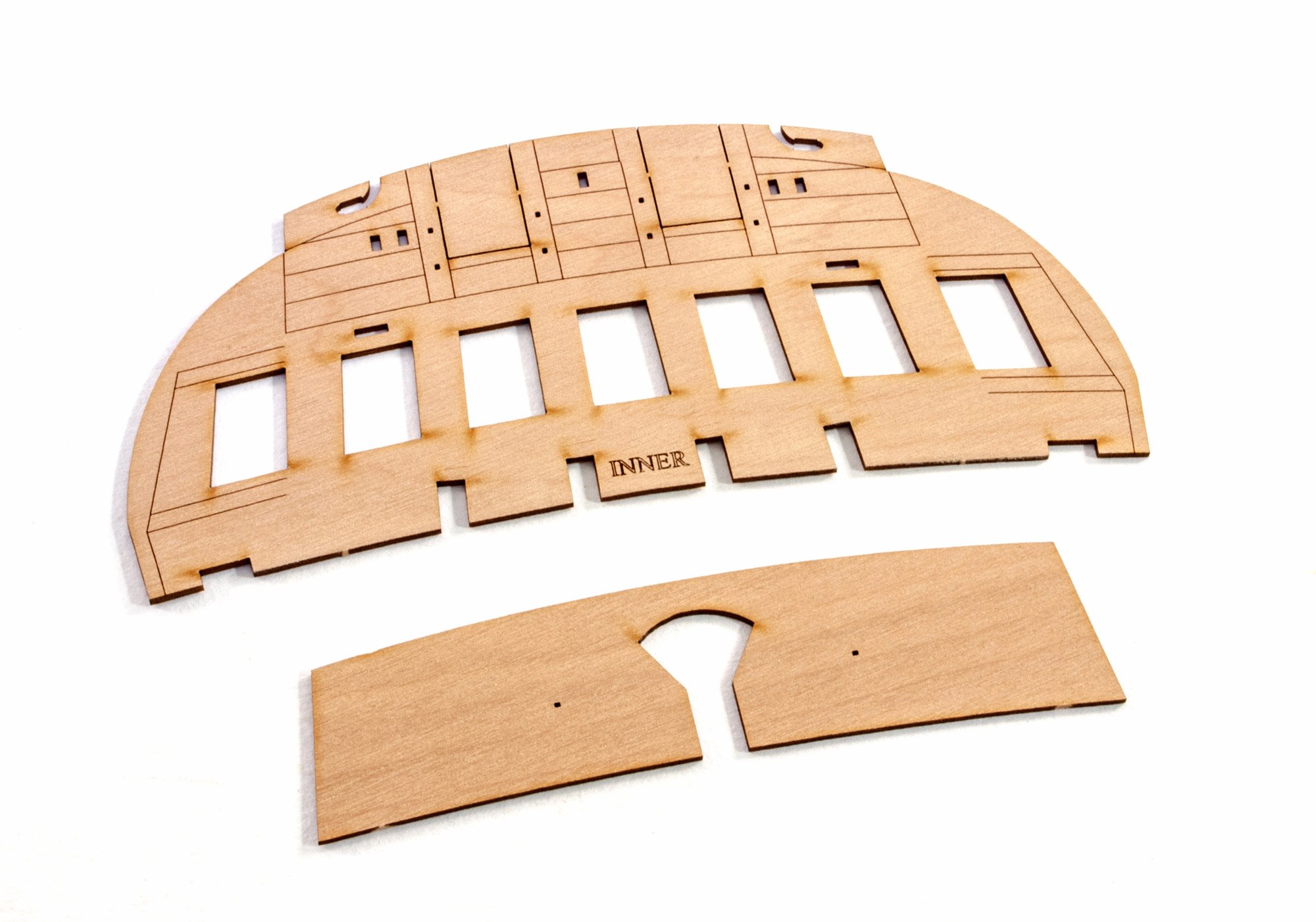
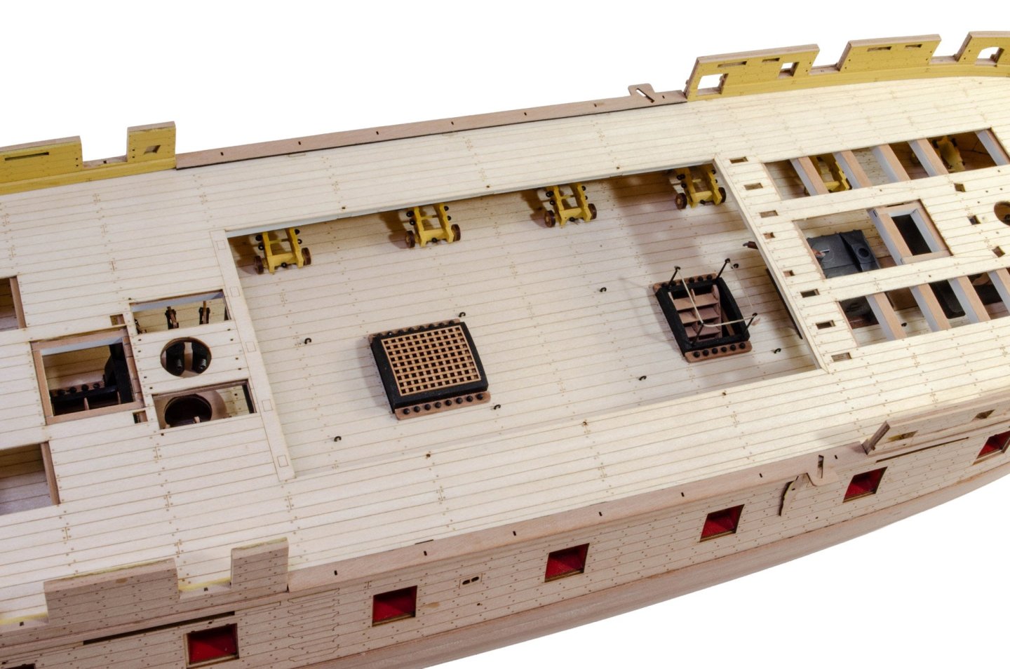
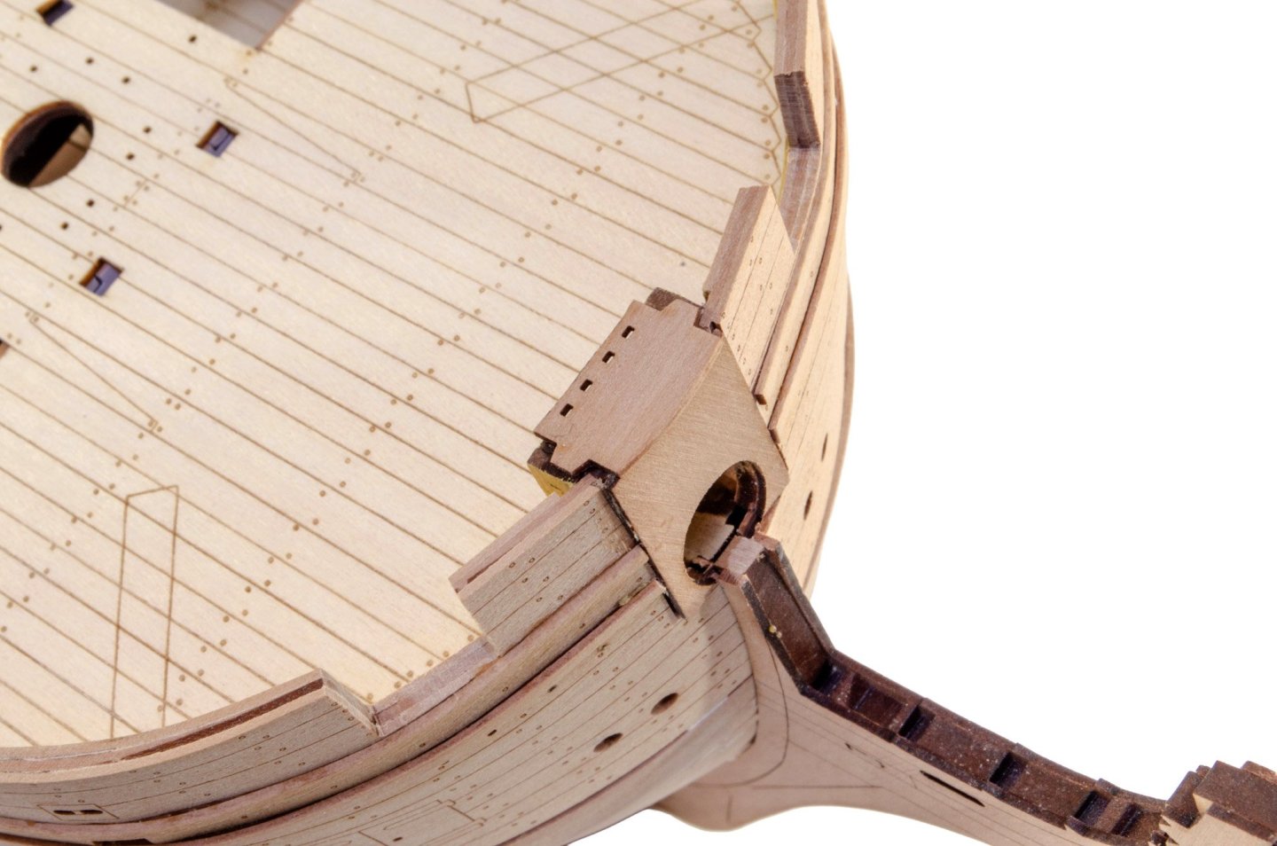
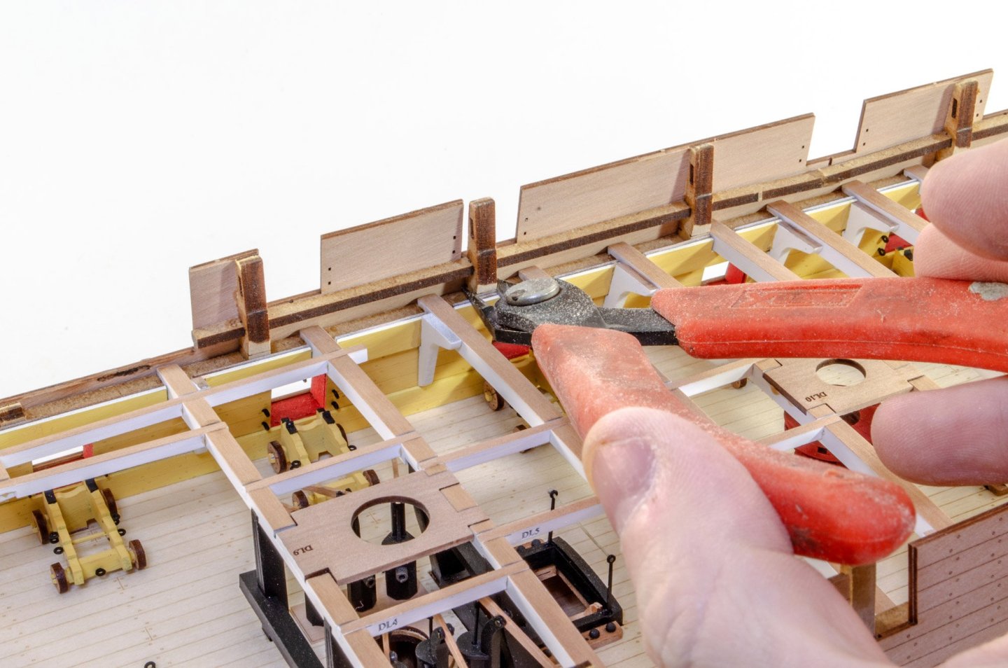
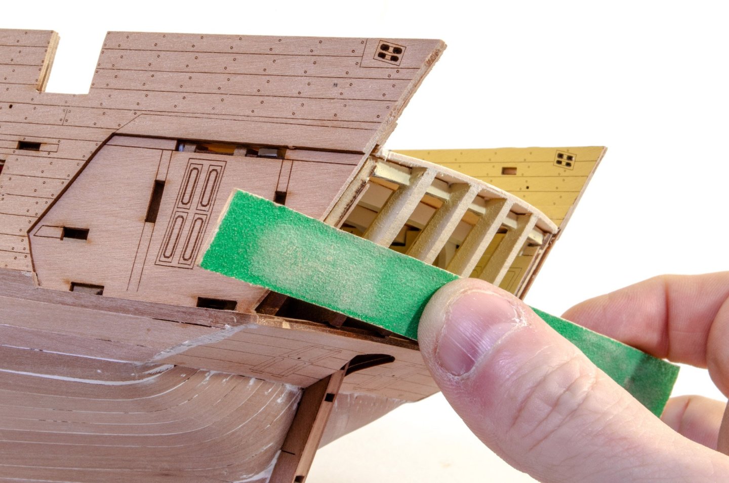
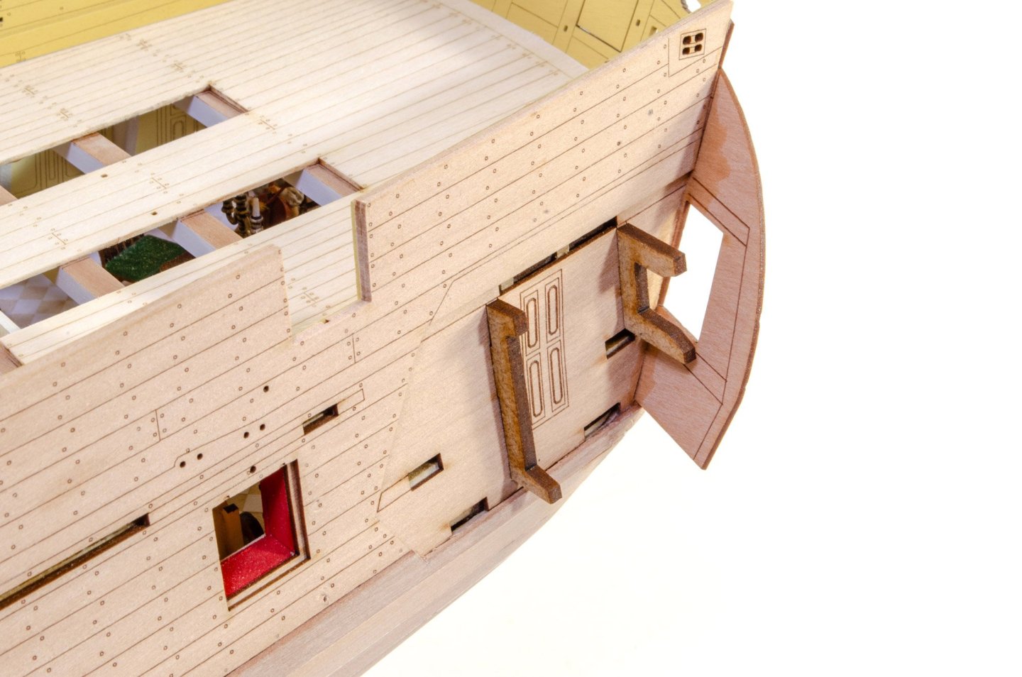
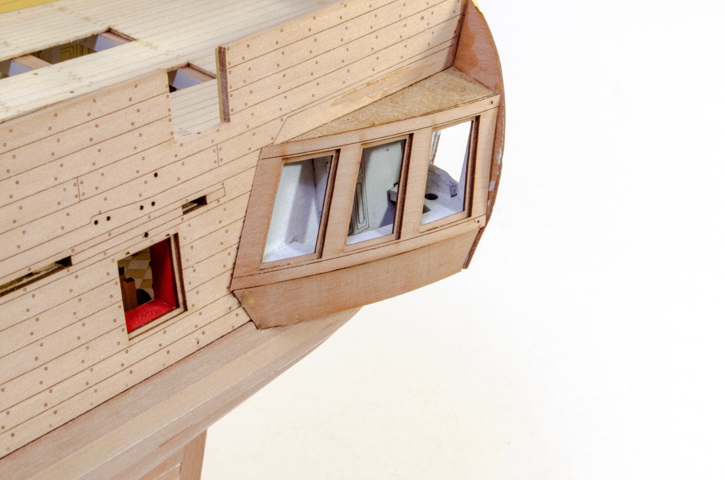
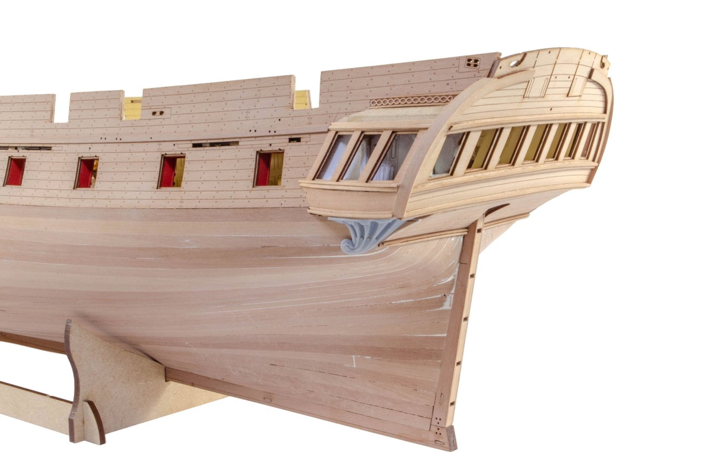
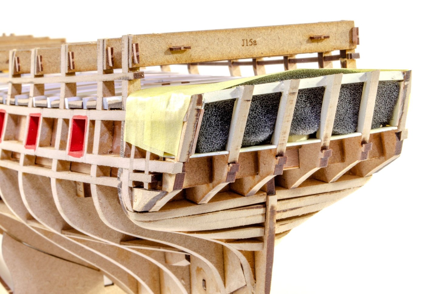
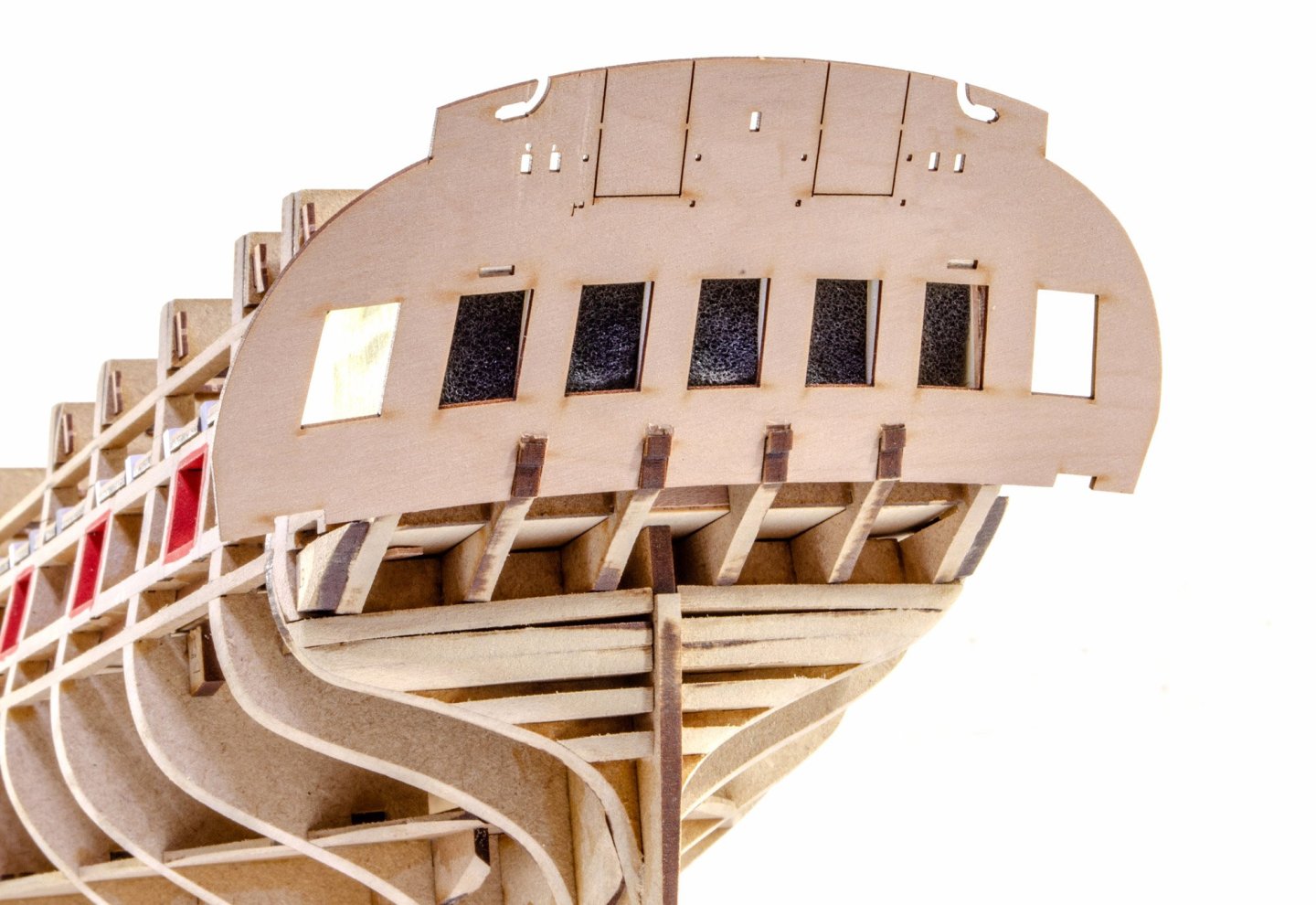
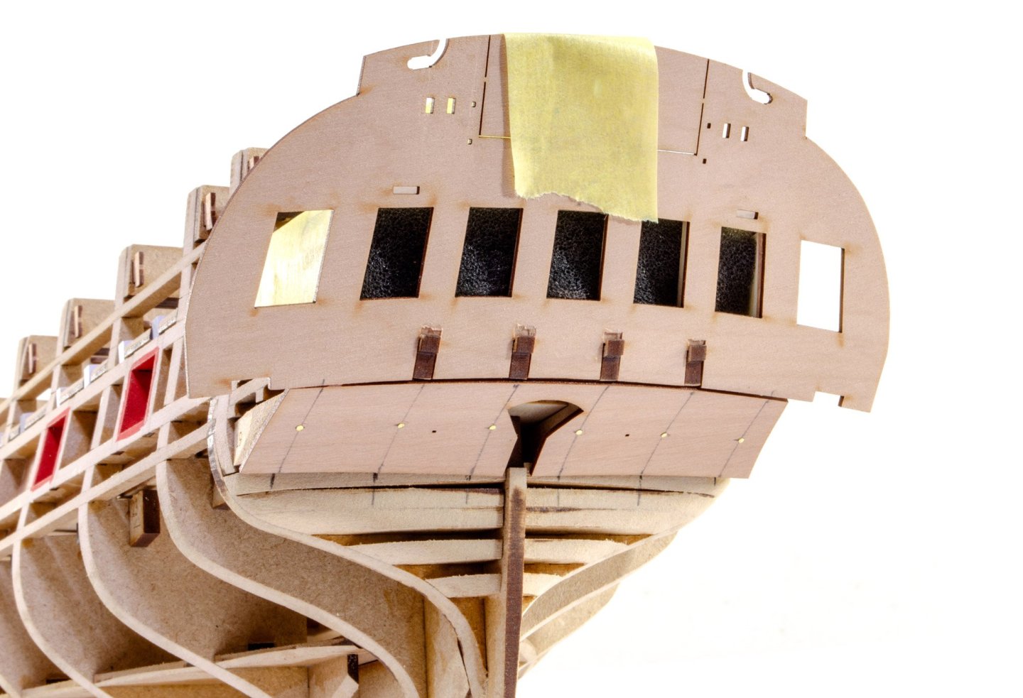
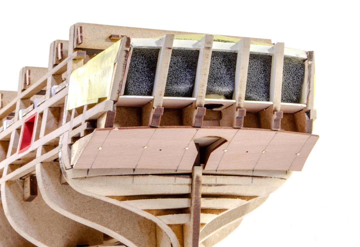
Another update! The hull now receives its pear planking and engraved outer bulwarks (once the inners are glued). We can now dispense with the remaining visible MDF structure. This is now snipped away, pending the main deck being laid. The deck is then glued down and it's time to add the inner bulwarks. Here are the forecastle inner bulwarks. These fit like a treat! You need to soak the fore areas though and leave them to thoroughly dry while being clamped into the bow area. The bulwarks are then removed, painted and then finally glued, both here and on the quarterdeck areas. The triple-layer bulwarks are now levelled along their top edges and the various gun ports and other openings are cleaned up. The catheads are built and then the forecastle openings are suited to fit these assemblies. These aren't glued in at this stage. We can now return to the stern area. Before be can do any fitting here, the back needs to be flushed off, meaning the bulwarks and spirket will need to levelled properly. With the stern fascia temporarily in position again, the quarter gallery frames are now constructed. The inner stern area has the framework angles engraved on them, so getting those MDT frame parts in position is foolproof. There are two layers of pear around the windows area, creating those recessed areas for the panes. The lower panel is a single piece of pear. The stern fascia can now be glued into place. To finish the stern (almost) various rails are fitted, as well as some beautiful 3d-printed drops for the quarters. The only decor to now be fitted are some engraved laserbak details around the outer circumference etc. At that point, the whole stern will change again. Hope you like the work so far.


- 145 replies
-
- 46
-
-
-
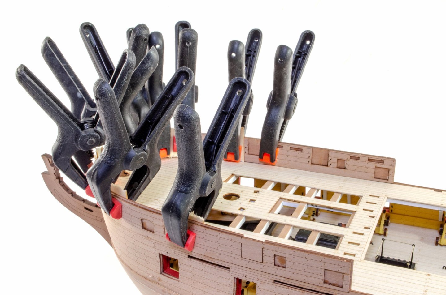
You'll also notice the jigs are back in situ. Those will be there until the hull is fully planked and sanded. They just give the hull some nice rigidity while being manhandled.
-
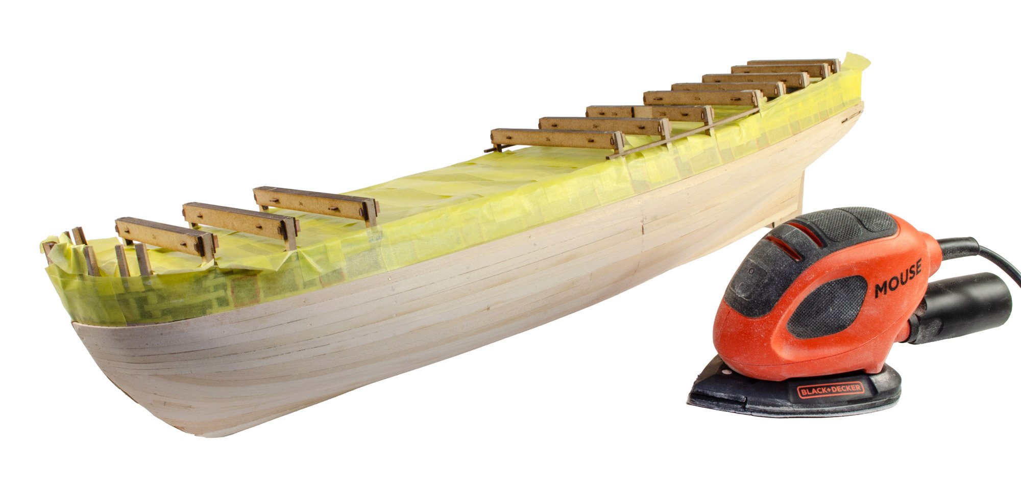
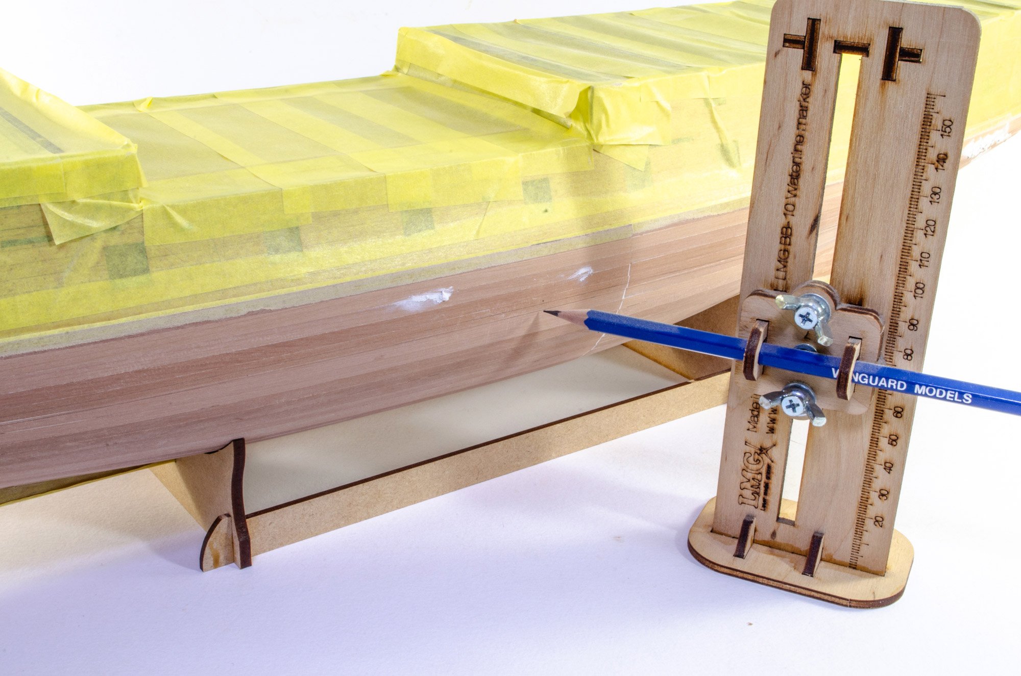
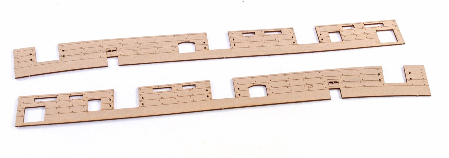
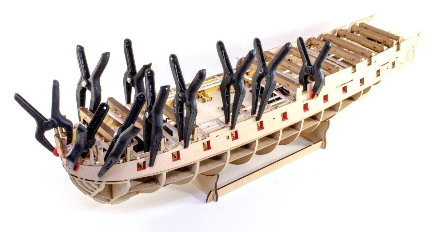
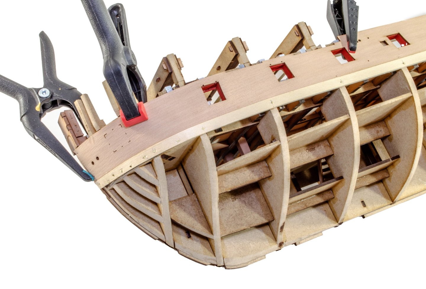
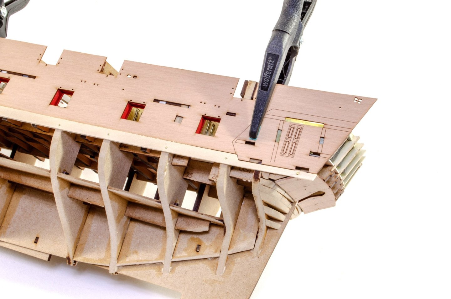
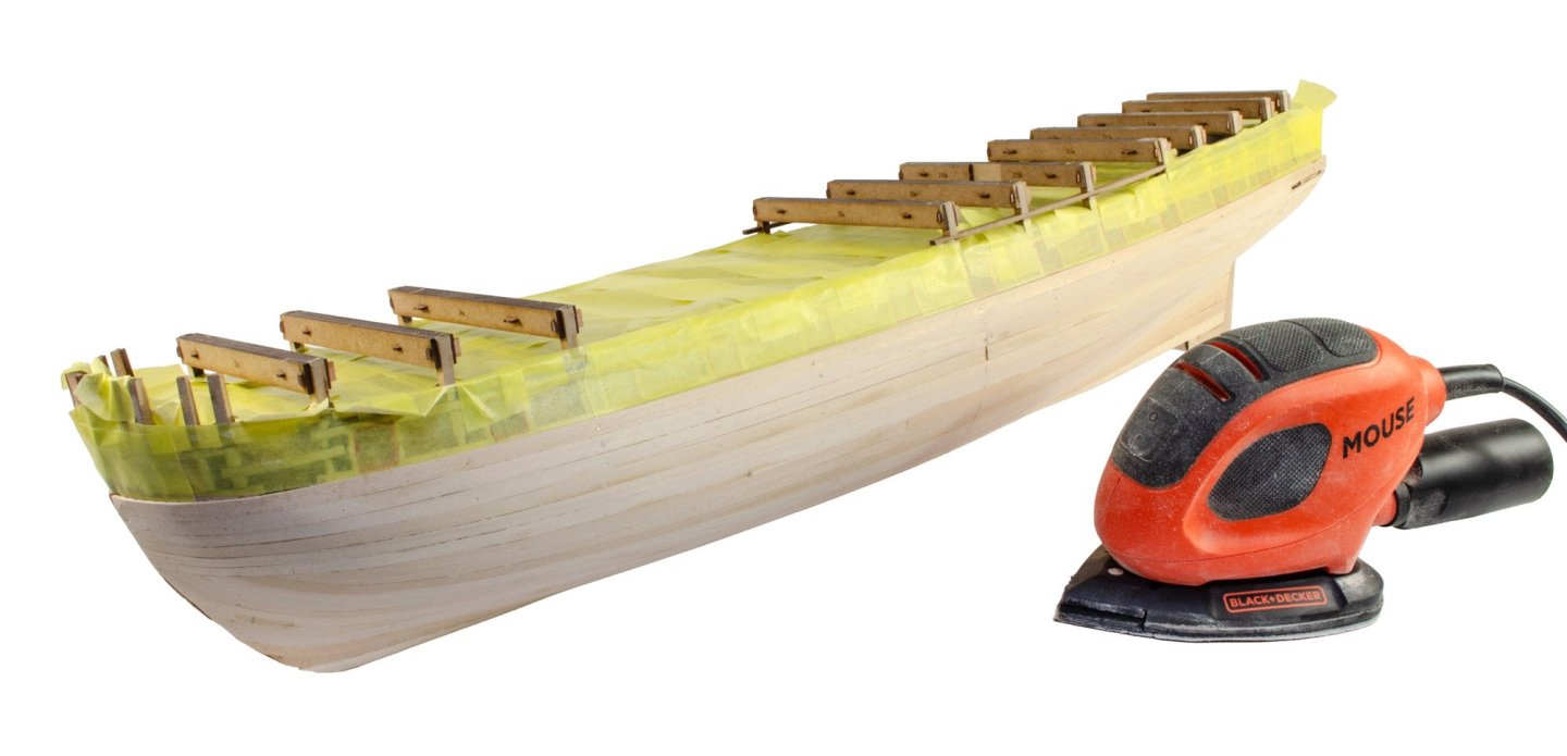
My apologies for being so slack on updates. Surprise is now unrecognisable from my last update, and some of you have already noticed the image change on the homepage of Vanguard Models website. Anyway, here we go... The stern of Surprise has been tackled in a different way that previous releases, removing any modeller error where the stern fascia could possibly be located too low on the hull. This release includes protrusions on the vertical stern timbers. These contain slots into which the stern fascia fits. Once the stern is chamfered to shape, the inner stern fascia is then temporarily slotted into place, and then the lower counter can be properly positioned and glued into place. The inner stern fascia can then be removed while other hull work continues. Some of the largest parts in the kit are the first layer of outer bulwarks. The front end of these are soaked in hot water and then clamped around the bow for 24hrs until dry and they regain their normal size. Once dry, the bulwarks are CLAMPED into place....NO GLUE! This is simply to help align the first hull plank. The first layer of planking can now begin, starting with lime. With this in place, the bulwark can be removed until later. Once complete, the hull is sanded smooth. Before this happens, a temporary plank is placed above the first plank. Sounds odd? Ok, HMS Surprise does NOT have wales on either side. Instead, the main hull planking protrudes slightly beyond the bulwarks. To achieve this, we first use 1.5mm lime planking. (the inner bulwark was only 0.8mm). The temporary plank is to prevent the modeller from accidentally running inwards along the top side while sanding. When the hull is sanded, the plank and tape (to stop dust ingress), can be removed. Note the sanding mouse too. This is now what I use for large hulls. I now add a waterline which is about 5mm below the actual one. Everything above this has any slight gaps filled. Below the waterline though, we'll of course be coppering. More soon.


- 145 replies
-
- 31
-
-
Access denied?
James H replied to amateur's topic in Using the MSW forum - **NO MODELING CONTENT IN THIS SUB-FORUM**
The error can actually disappear, as you see. That usually happens if a user's IP refreshes, or they turn on/off a VPN (or change VPN location). -
I love '%s'. Wonderful company.
-
Fund raising
James H replied to Russ2025's topic in Using the MSW forum - **NO MODELING CONTENT IN THIS SUB-FORUM**
We operate modular software which will integrate within certain areas of the forum. Unfortunately, I can't just move these things into different areas or modify them to operate in more than one location. -
Access denied?
James H replied to amateur's topic in Using the MSW forum - **NO MODELING CONTENT IN THIS SUB-FORUM**
I just need the IP from the screen you get, then I will whitelist it. -
Any movement on this?
-
kit review 1:48 La Renommée 1744 - CAF Model
James H replied to James H's topic in REVIEWS: Model kits
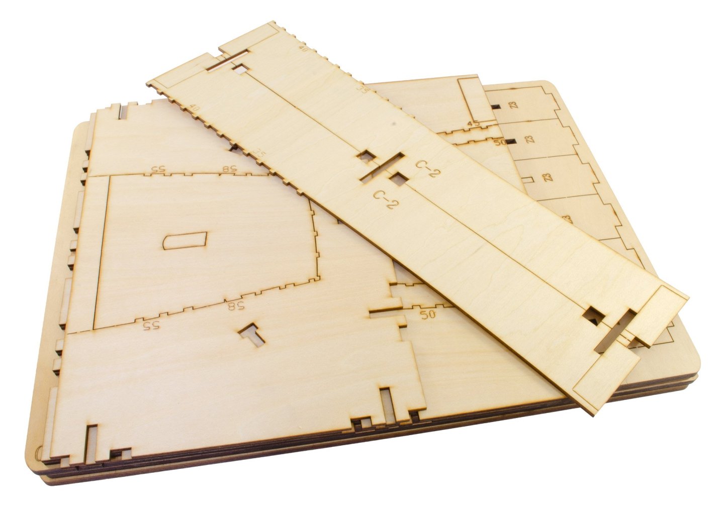
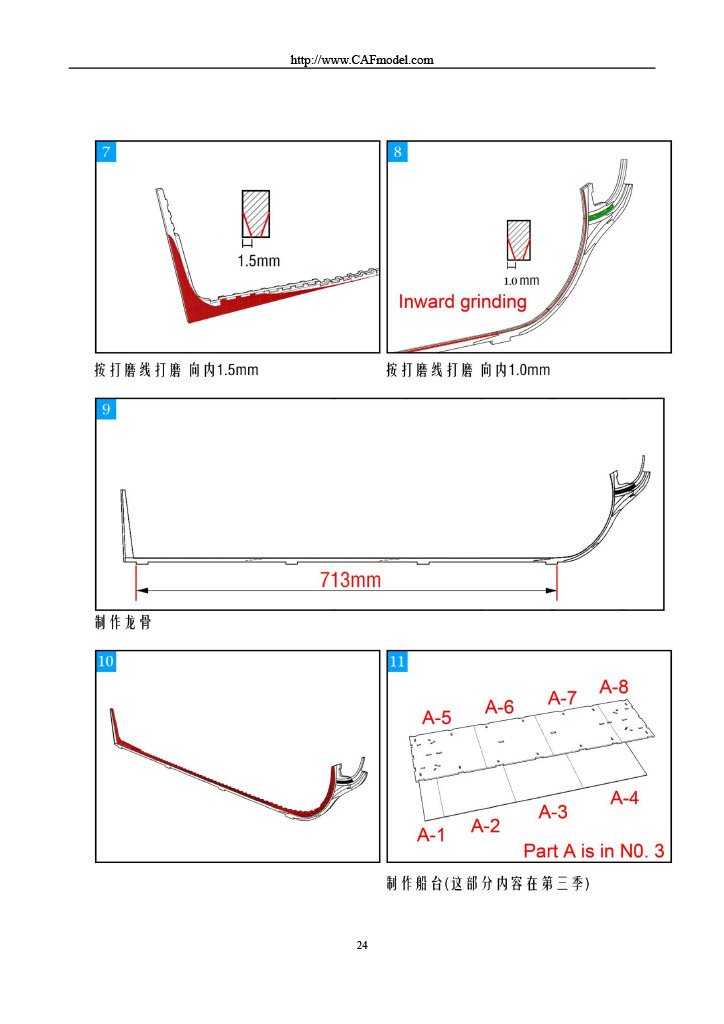
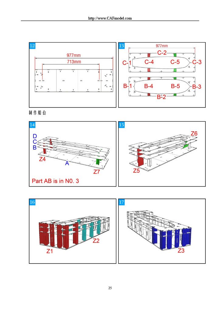
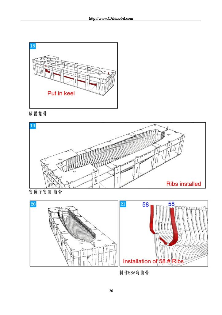
PART 4 This pack is very similar to the previous in that it contains more framings, but also the keel, meaning that the hull really can now start to be assembled. Everything is packed into a single cellophane wrap as before. We've also been given more CNC-machined parts. It's quite unusual to split that large cradle into more than one pack, and not to have that as the initial box too. Instructions If you'd like to see the whole instructions for this and how these first four parts come together, then they are available directly from the product page. Please check them out and if you're already tempted by this release, please tell Tom you've been following this topic. Part 4.5 will follow in a day or two.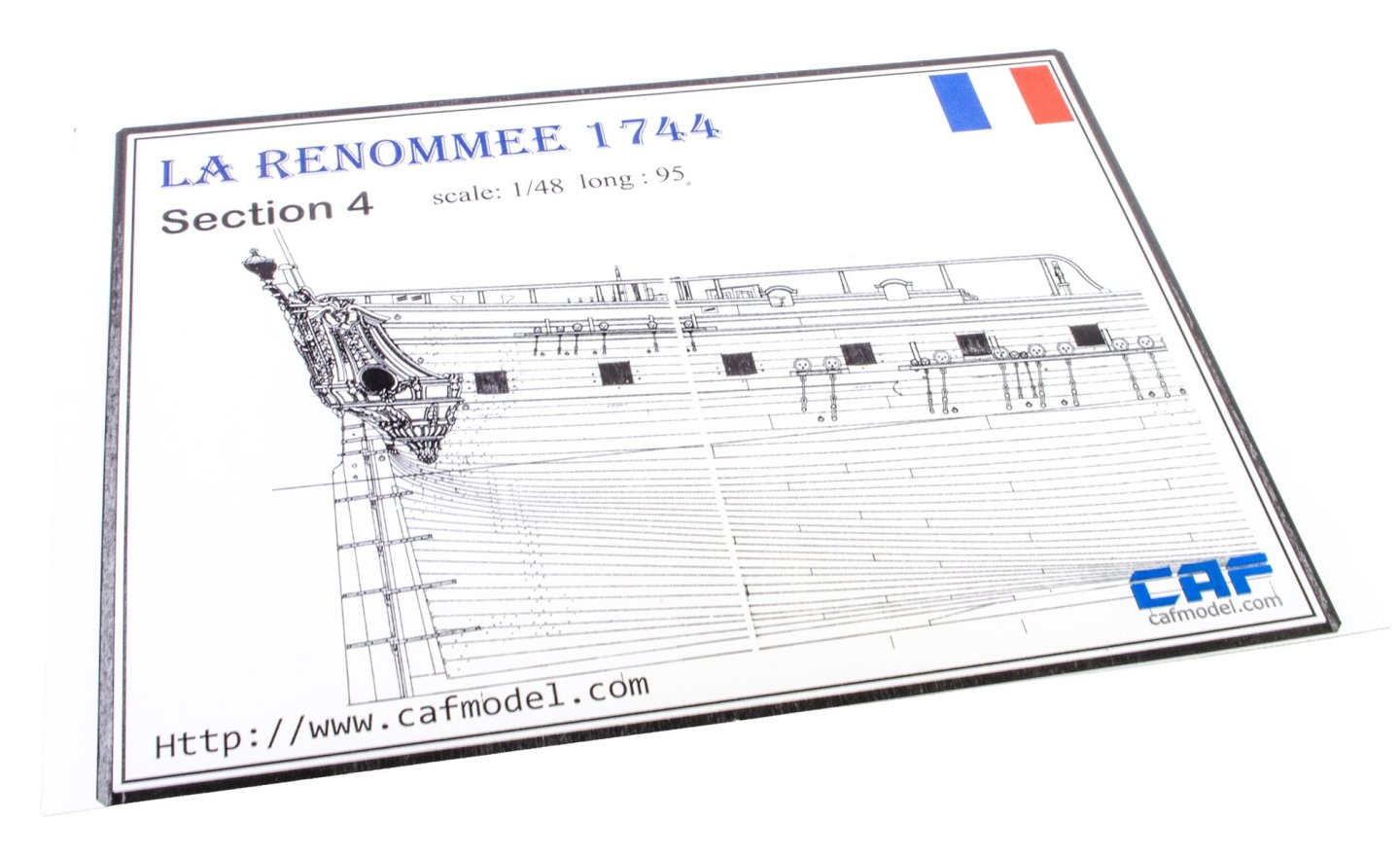


- 16 replies
-
- 12
-
-
- cafmodel
- la renommee
- (and 1 more)
-
kit review 1:48 La Renommée 1744 - CAF Model
James H replied to James H's topic in REVIEWS: Model kits
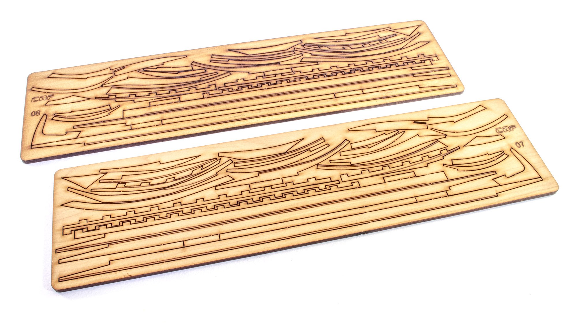
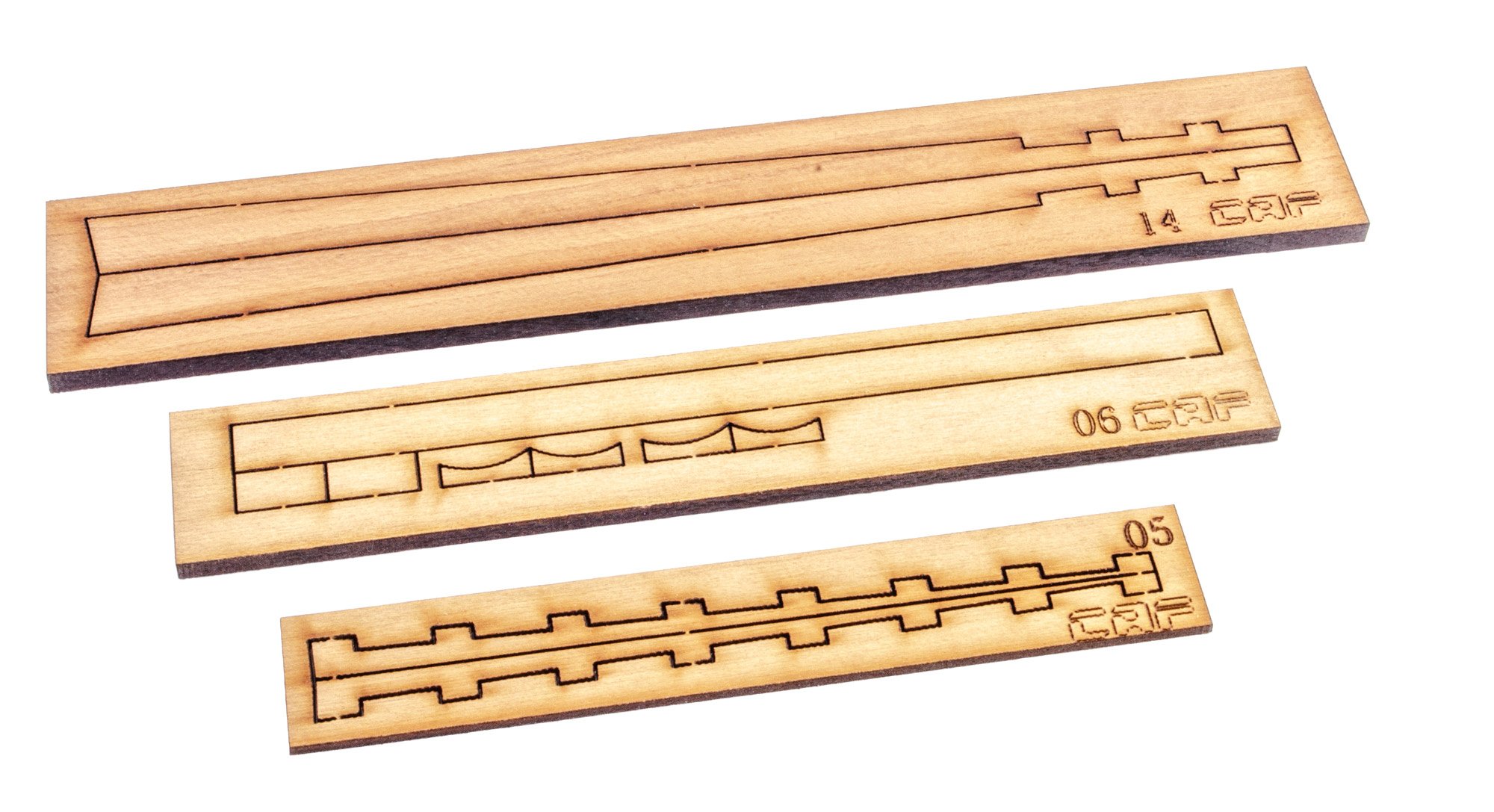
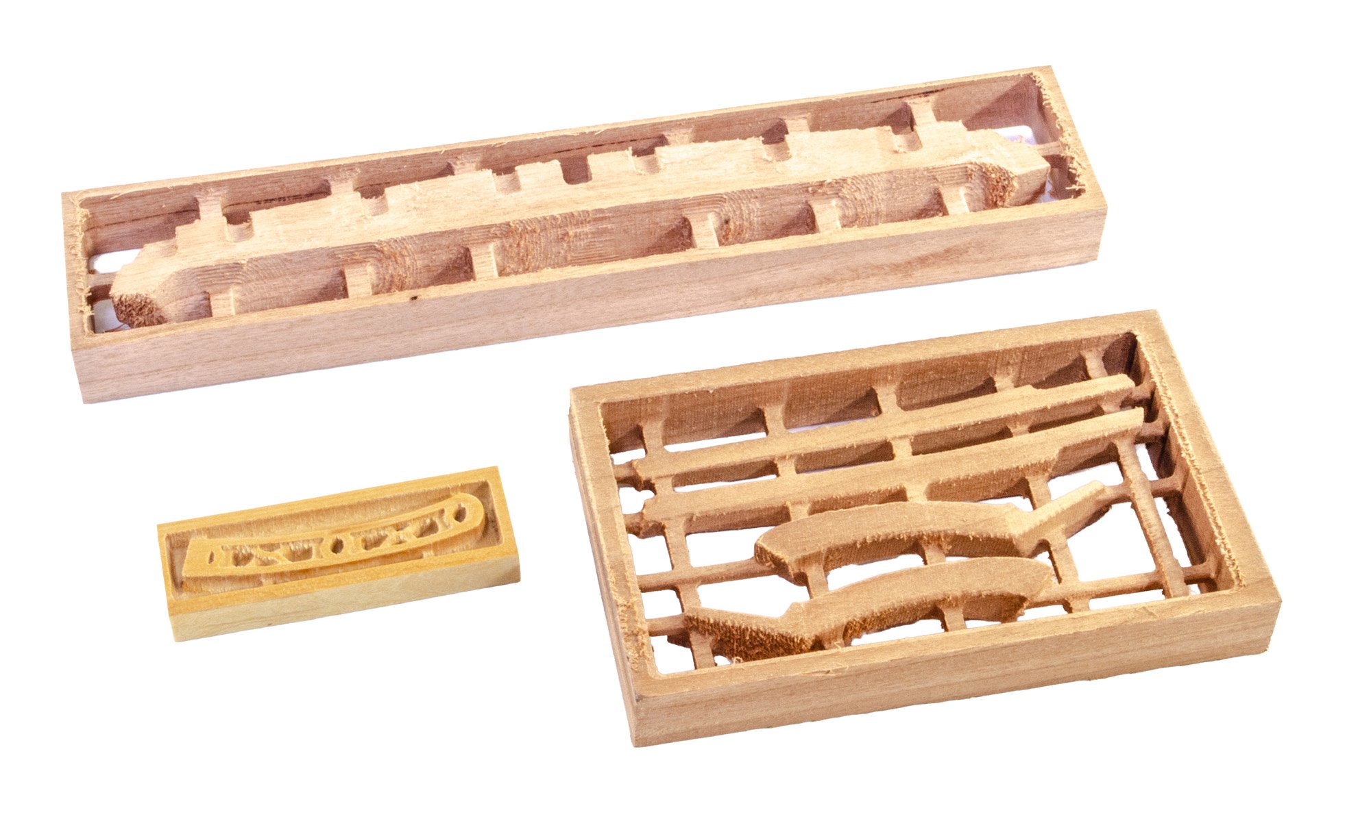
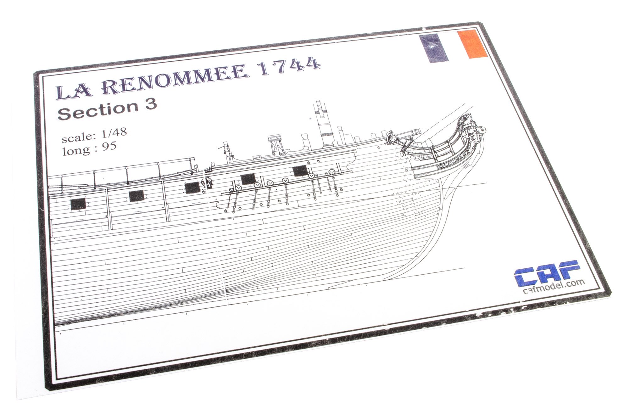
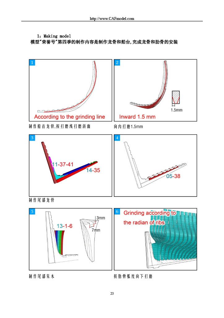
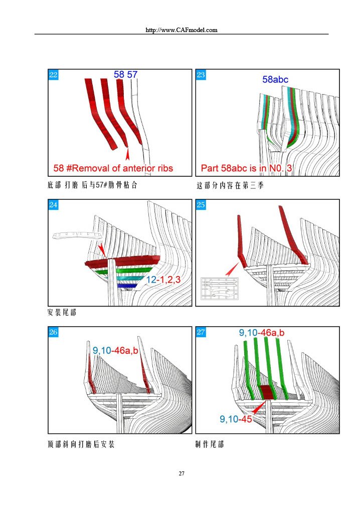
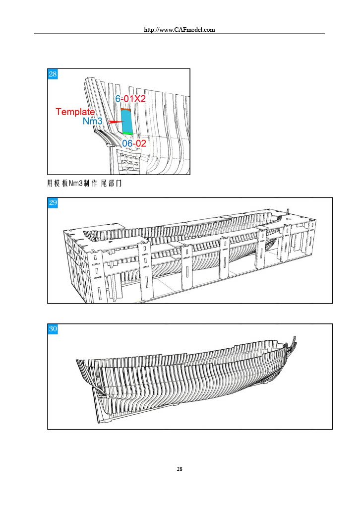
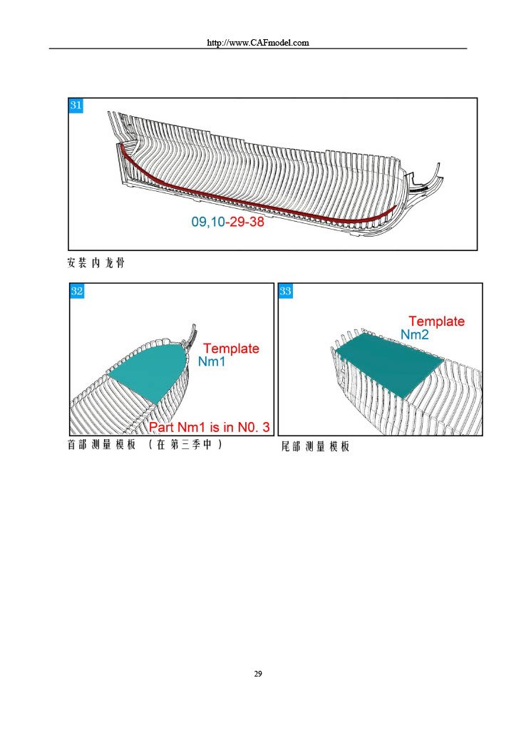
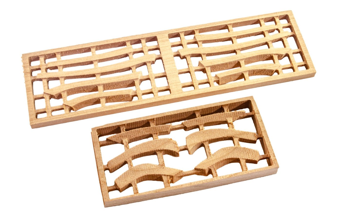
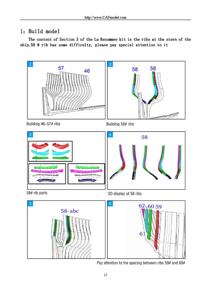
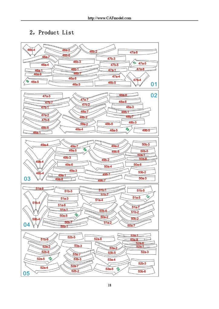
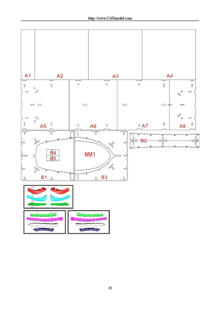
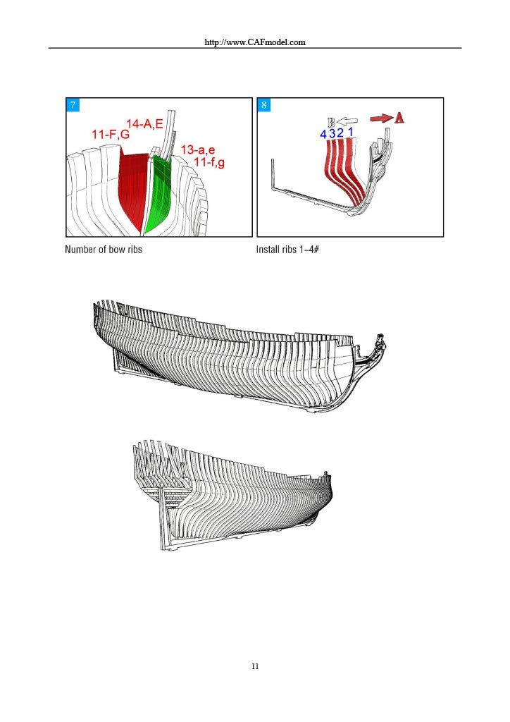
PART 3 This is beginning to look all too familiar...but WAIT! We now also have parts for the hull jig! Not all though, as some are also supplied in the next pack, but at least you get a good start in getting that very large construction underway. As you'd expect, the cradle is constructed from laser-cut plywood. All parts in this pack are sealed in a single cellophane wrap. As well as more framing and that cradle, there are also two small frames containing CNC machined parts which relate to the stern of La Renommée. These just want freeing up and carefully sanding smooth. Instructions As well as another full size frame layout sheet, you can see the use of colour in the instructions, to denote key areas of construction, including the use of those CNC parts. Part 4 will follow soon.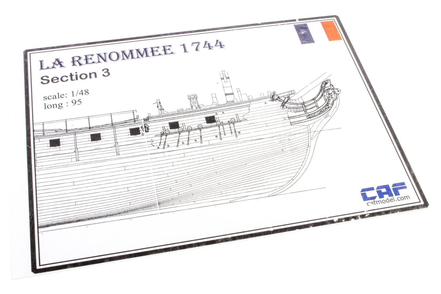


- 16 replies
-
- 5
-
-
- cafmodel
- la renommee
- (and 1 more)
-
kit review 1:48 La Renommée 1744 - CAF Model
James H replied to James H's topic in REVIEWS: Model kits
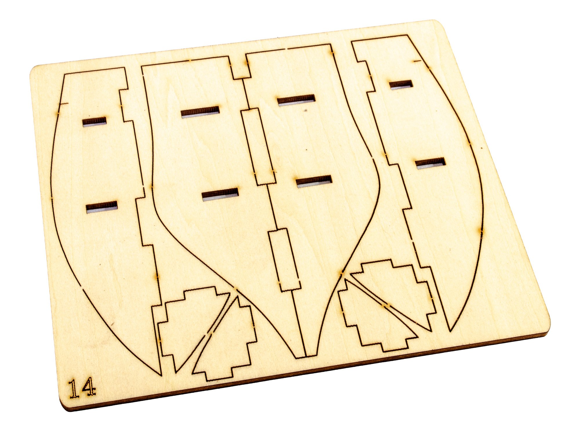
PART 2 This pack is largely similar to the previous, except a plywood jig is included for the modeller to build the bow frames around. At this stage, there's still no cradle as we are concerned with the building of those many frames. All parts are packed into a single cellophane wrap. After unpacking and photographing, tape was used to re-bind the parts to prevent any twist until I come to build the model. Instructions This is very similar to Pack 1, except the bow jig is illustrated. This looks very simple to build. Again, a full size sheet is included over which to build the numerous hull frames. Next post will show Part 3.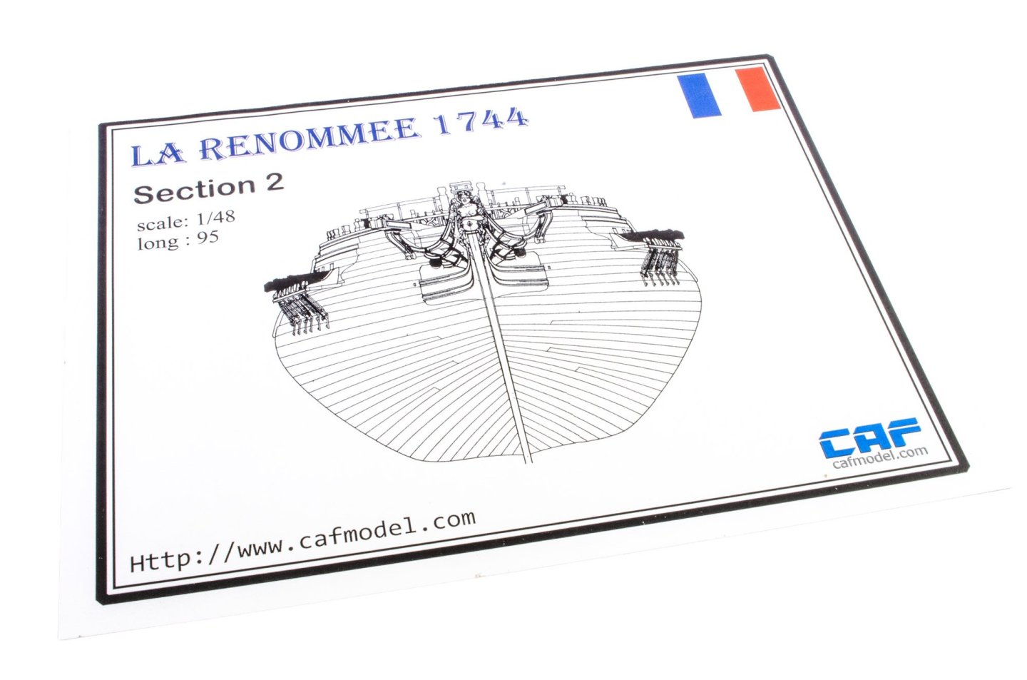

- 16 replies
-
- 4
-
-
- cafmodel
- la renommee
- (and 1 more)
-
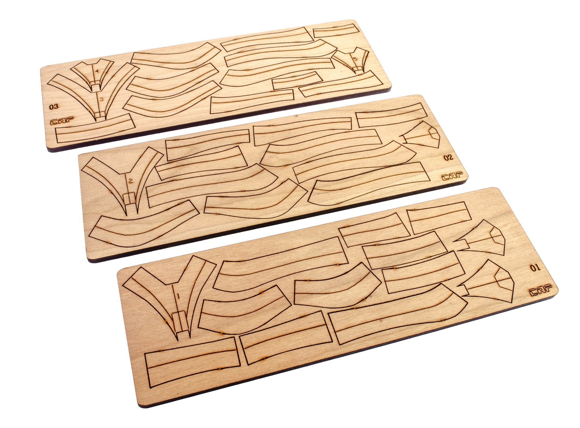
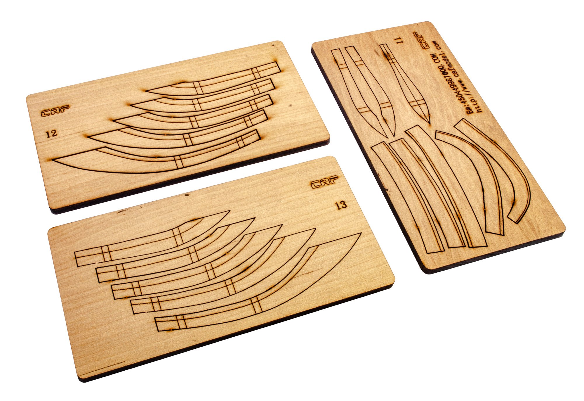
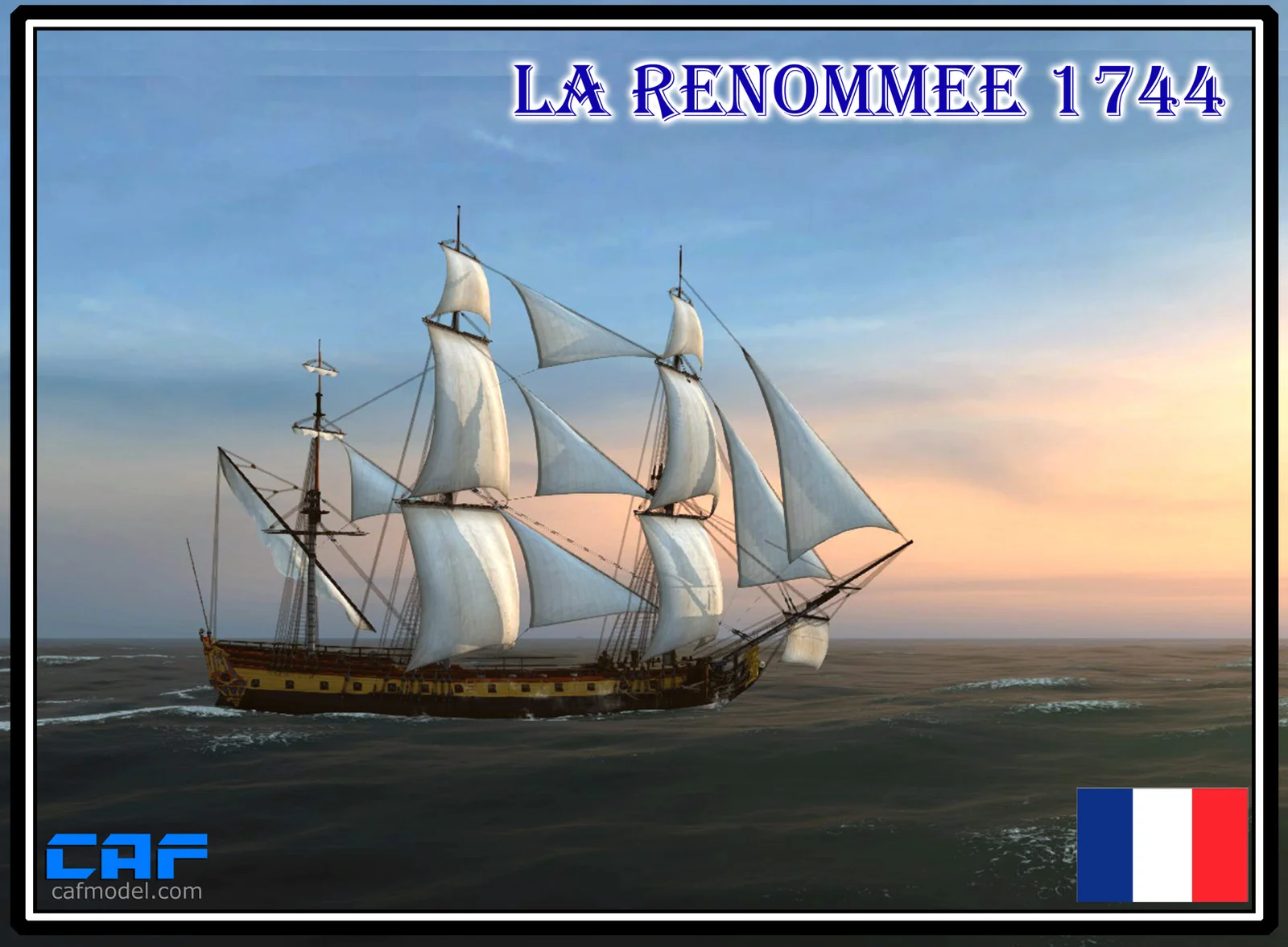
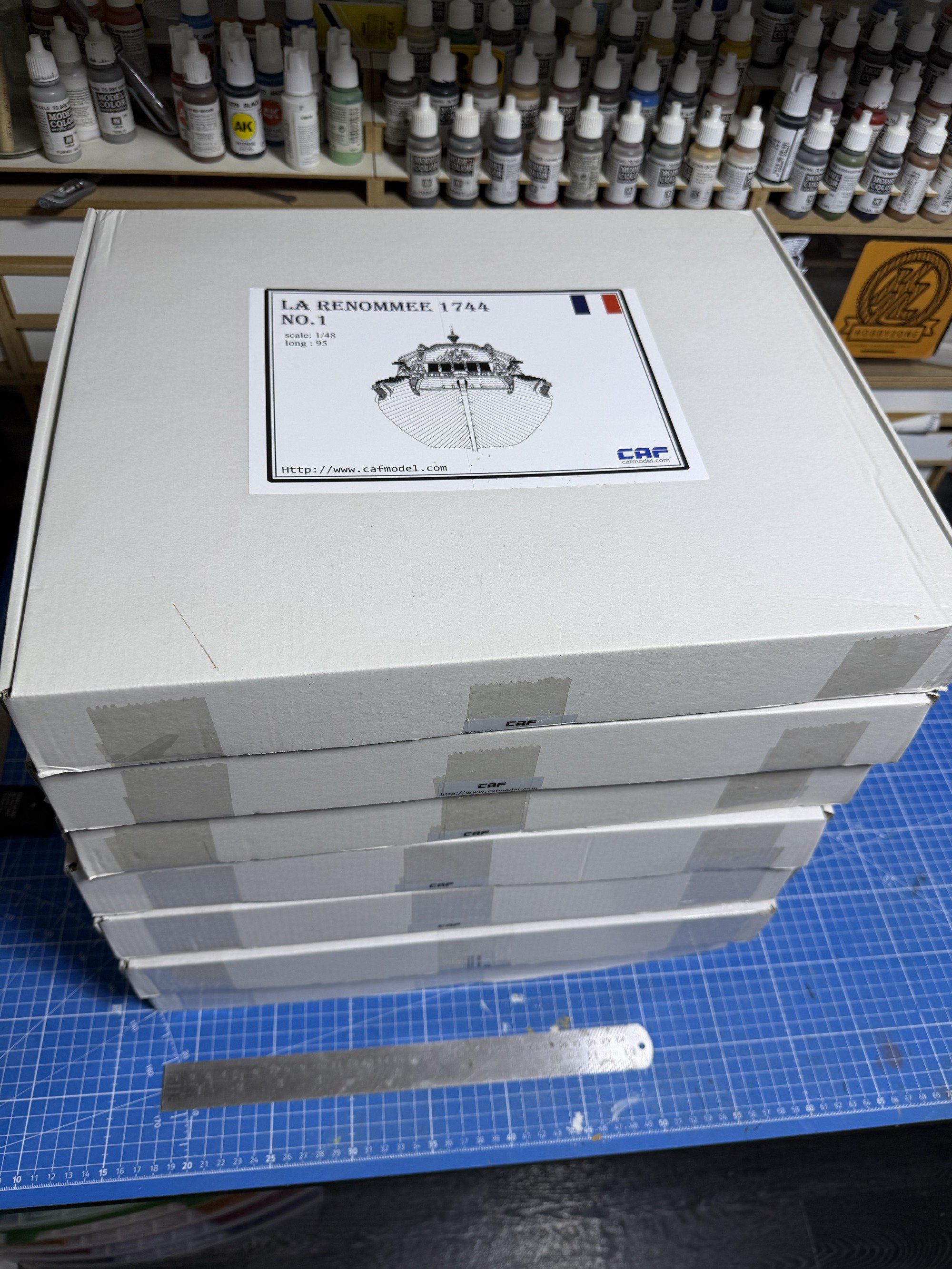
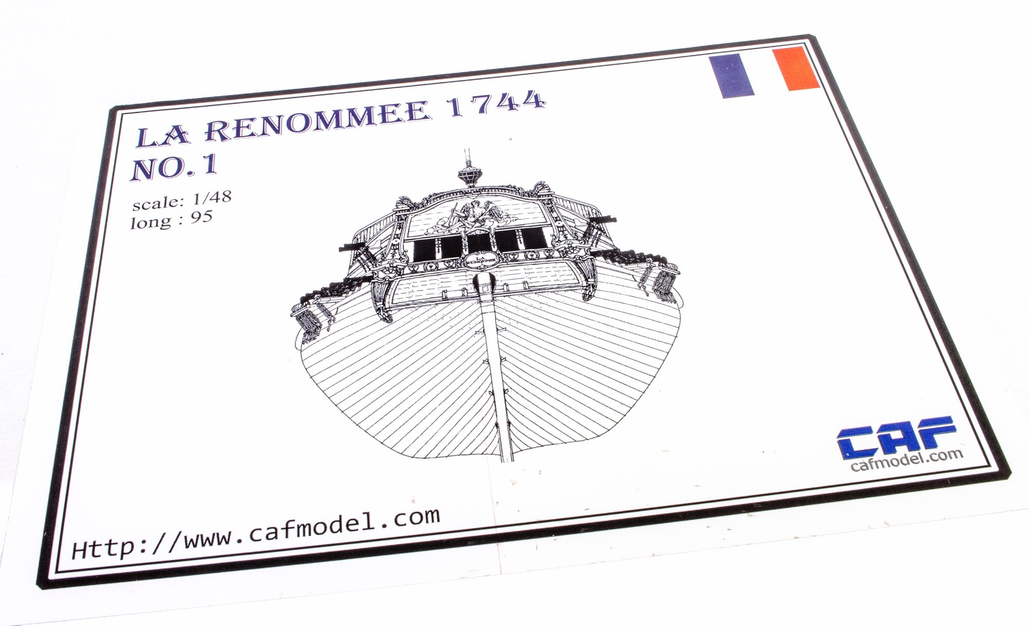
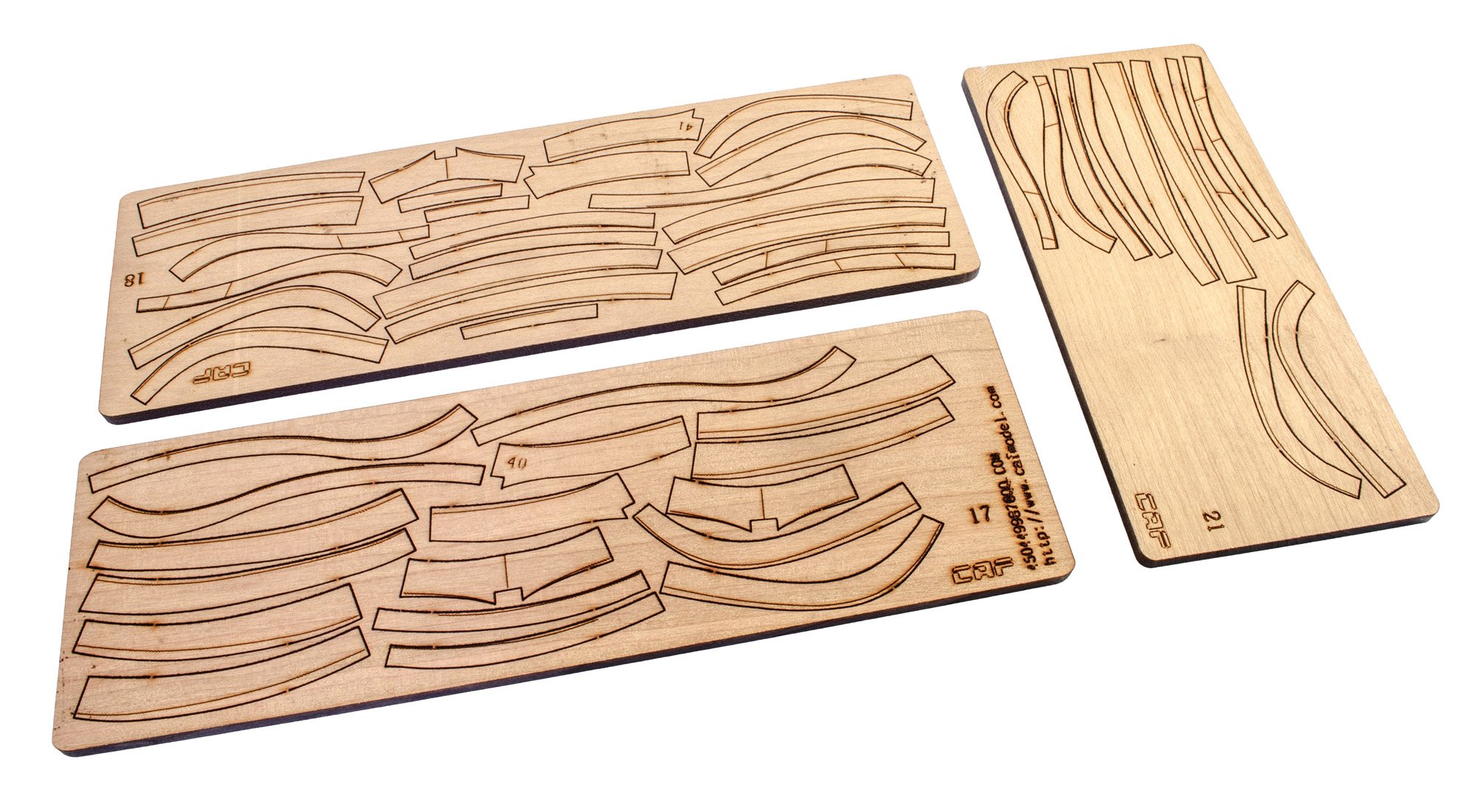
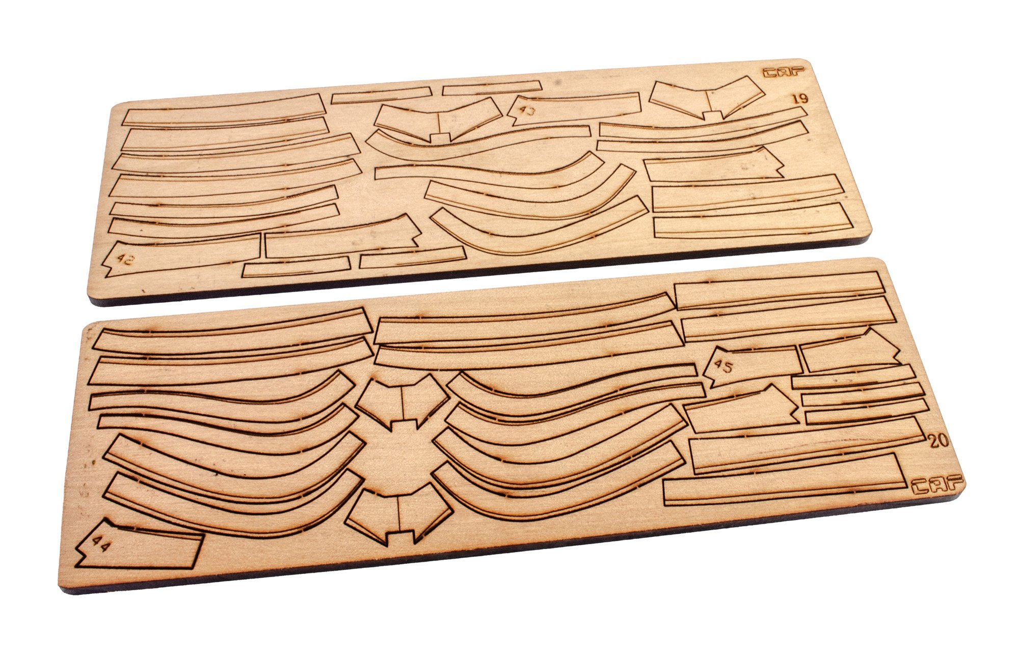
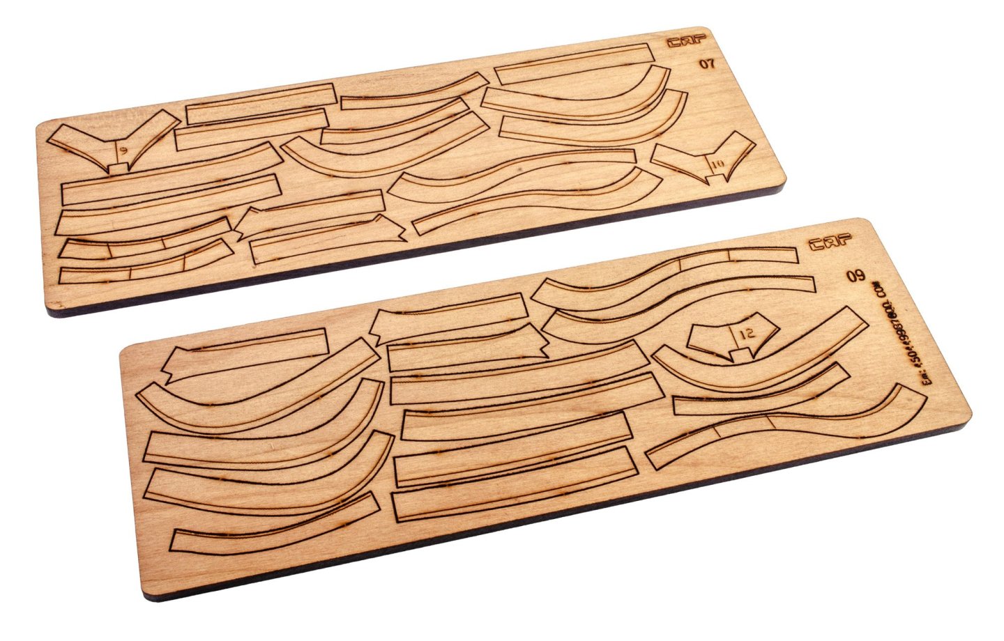
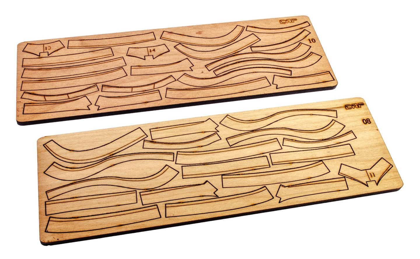
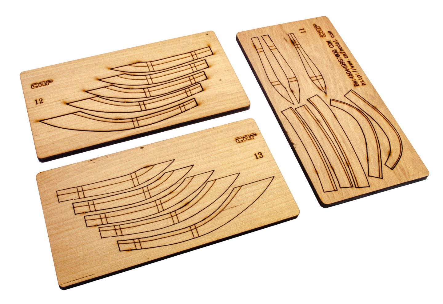
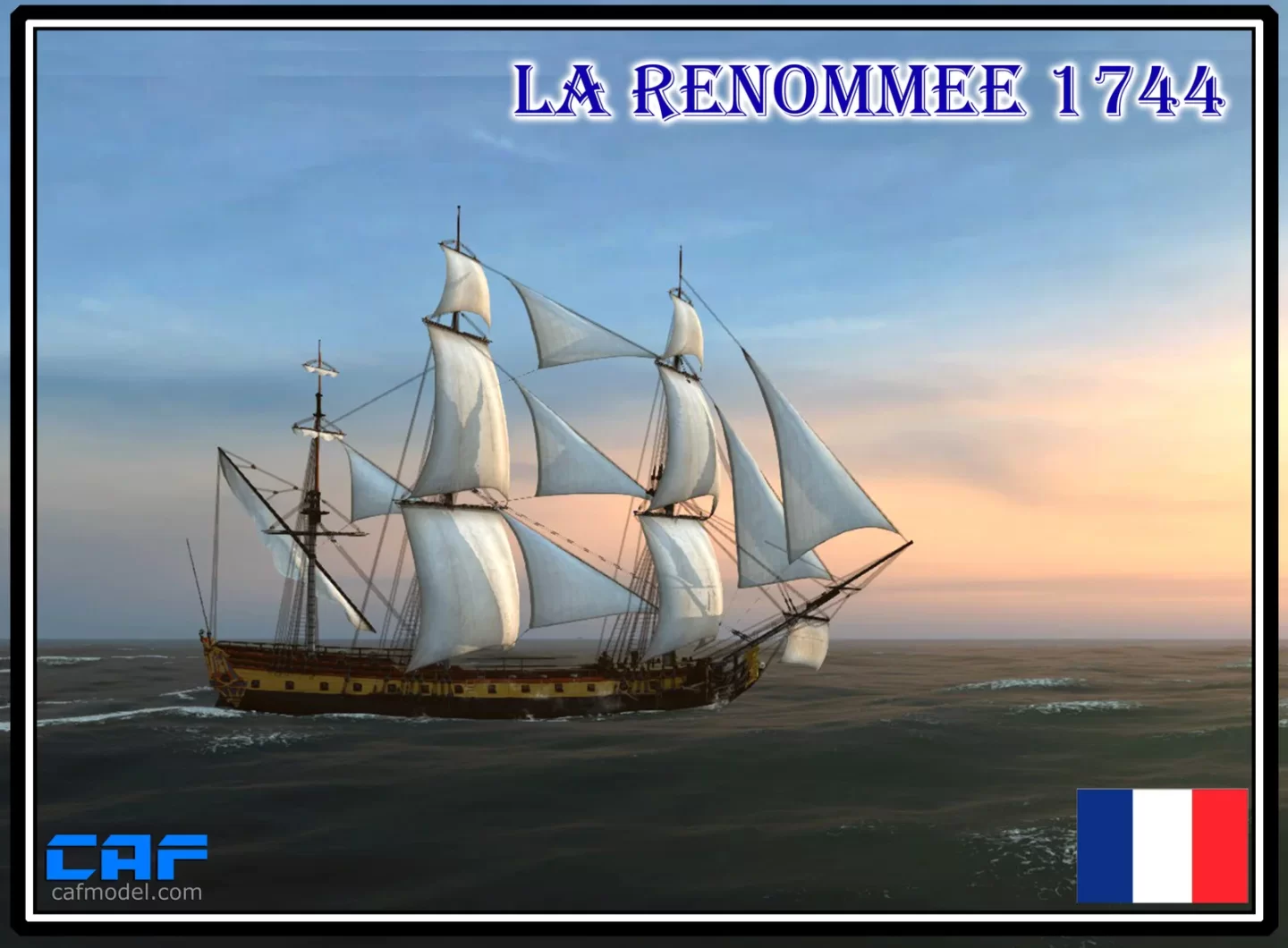
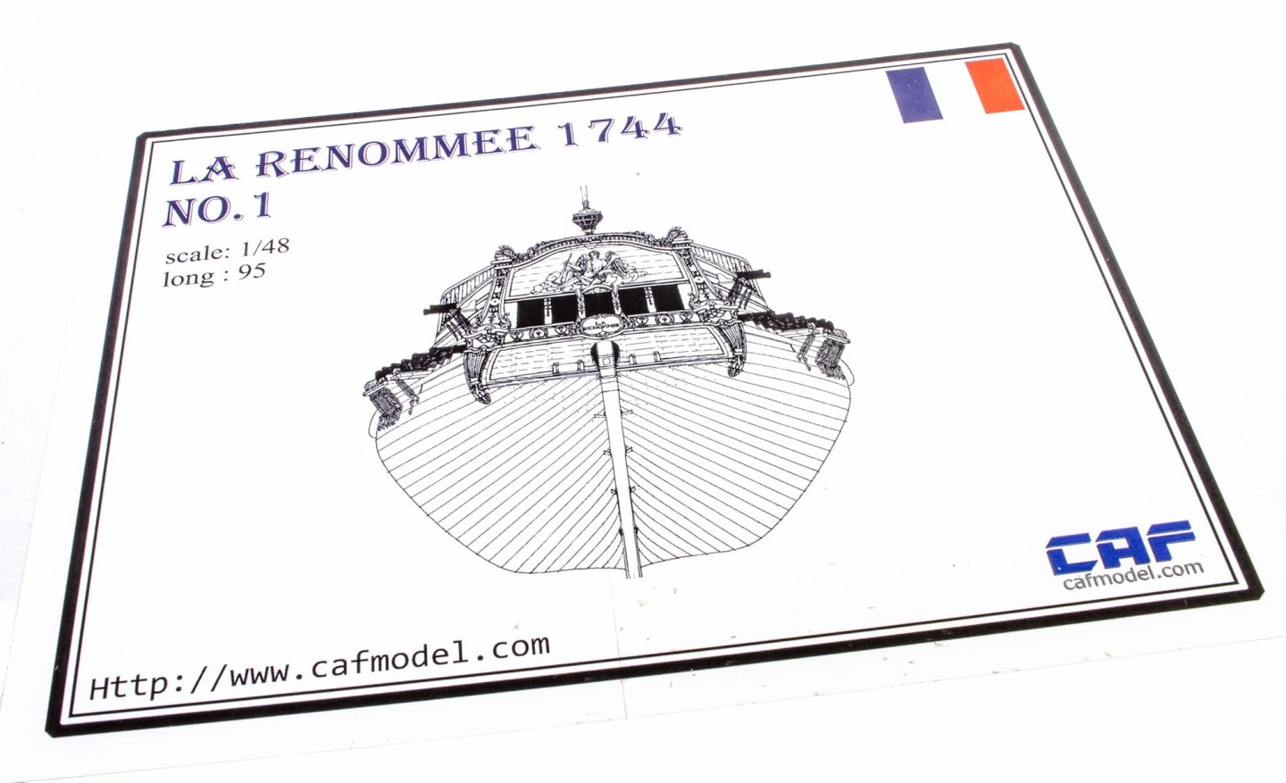
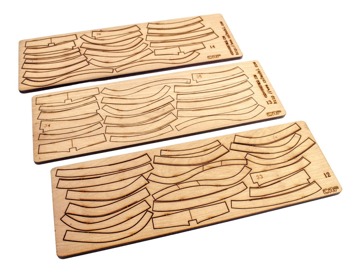
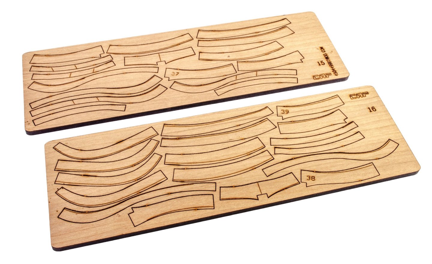
1:48 La Renommée 1744 CAF Model Kit available in chapters - check site for prices (complete kit around $2500USD as time of writing) History La Renommée was a French frigate launched in 1744 at Brest during the War of the Austrian Succession, at a time when France was refining the fast, lightly built frigate type that would soon dominate naval scouting and commerce warfare. Designed according to contemporary French principles emphasizing speed, maneuverability, and efficient firepower, she carried roughly 30–40 guns (depending on source and period) and was considered a capable and well-sailing ship. In 1747, while en route from France to the Caribbean, La Renommée was captured by the British after an engagement with HMS Dover in the Atlantic. Impressed by her design and sailing qualities, the Royal Navy took her into service as HMS Renown, reclassifying her as a fifth-rate frigate. Under the British flag she served for more than two decades in patrol, escort, and overseas duties, including service in the English Channel and the West Indies. After a long and relatively uneventful career, the ship was finally broken up in 1771, her longevity reflecting both the soundness of her original French construction and the Royal Navy’s appreciation of captured French frigate design. The kit Here is the kit spec, as given on the CAF website. In 1:48, this is a very large model, especially if you complete with the masts and rig. Scale:1/48 Length : 1230 mm Hull length: 927 mm Width: 550 mm Hull width: 250 mm Height: 950mm Hull height 250 mm Building jig included in kit Keel, rib, hull is in American cherry wood Hull and carvings are boxwood Boxwood figurehead with very high detail Deck uses white maple Guns, anchor, rudder hinge, brass casting, and many more metal fittings All laser-cut wooden sheets with quality wood ( minimal colour variation) POF kit, many high accurate ribs 8 pound class artillery * 26 4 pound class artillery * 4 English instructions A0 drawing 1:1 This is the latest kit, brought to chapter completion by CAF Model of China. The main release comprises SIX individual boxes, with an optional hefty Part 4.5 that contains all of the interior, should you with so fit it (and why wouldn't you!). So yes, I have SEVEN boxes here, and the weight is not insubstantial! I don't know if it's luck or design, but I've never had any import duty to pay on Chinese imports in the UK. All of these kits were sent in two shipments, with them being heavily protected and wrapped in heavy duty film. Everything arrived in A1 condition. All parts are individually sealed with a product label. PART 1 Like the first sets in the La Renommée series, this contains many sheets (cherry wood) or frame parts. All sheets are laser cut and contain engraved lines which help with alignment and bevelling. There is some char/resin residue on the rear of the sheets, but this easily comes away with some minor sanding. Pack 1 contains three wrapped packets of parts. Numbering on these is shown in the manual, with each sheet having a reference number. There are no metal parts or fittings in this pack. All of this will come later. Instructions The instruction booklet for this part is minimal as it merely shows the sheets and how the frames are built. There is also a large sheet over which the frames are assembled. Just remember to use some cellophane as a barrier so the parts don't stick to it. I will look at Part 2 in the next post.


- 16 replies
-
- 4
-
-
- cafmodel
- la renommee
- (and 1 more)
-
Kit review 1:48 La Renommée section - CAF Model
James H replied to James H's topic in REVIEWS: Model kits
Thanks for sharing that with us. Nice to see Tom with his finished project. I'm just editing the first four stages but having a nightmare with my Mac and the latest Tahoe software which has laid my 2019 MacBook Pro waste.