James H
-
Posts
6,043 -
Joined
-
Last visited
Content Type
Profiles
Forums
Gallery
Events
Everything posted by James H
-

New to ship modelling? But what do you build first?
James H replied to MSW's topic in Wood ship model kits
I hope you'll do a build log for this. -
new kit alert! New kit on the horizon - Winchelsea Nef
James H replied to James H's topic in Wood ship model kits
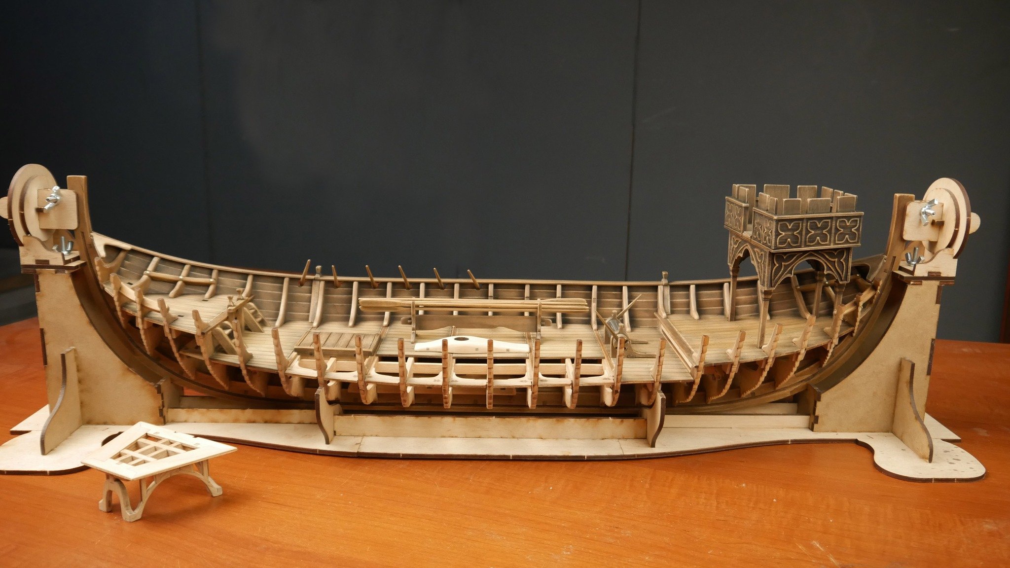
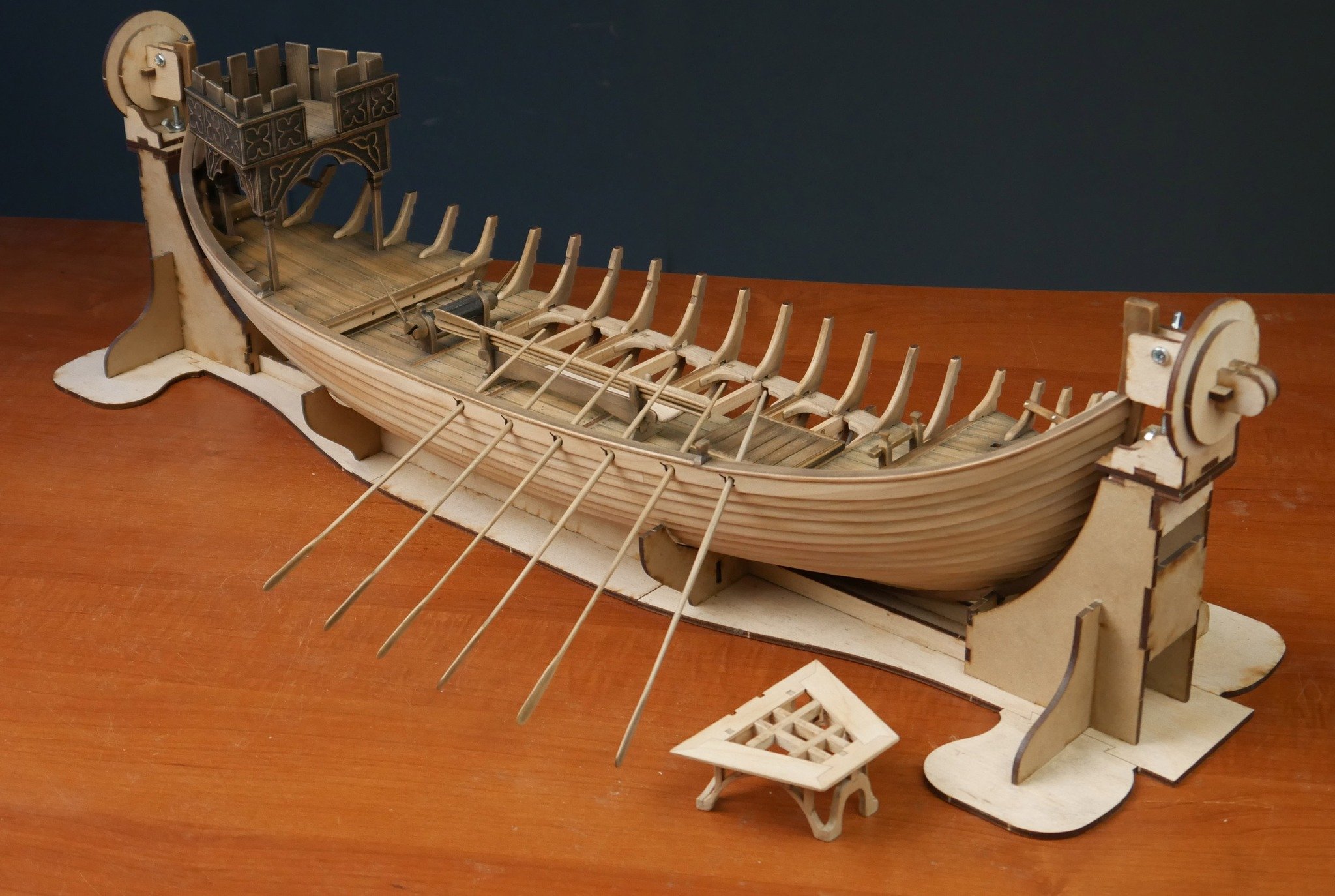
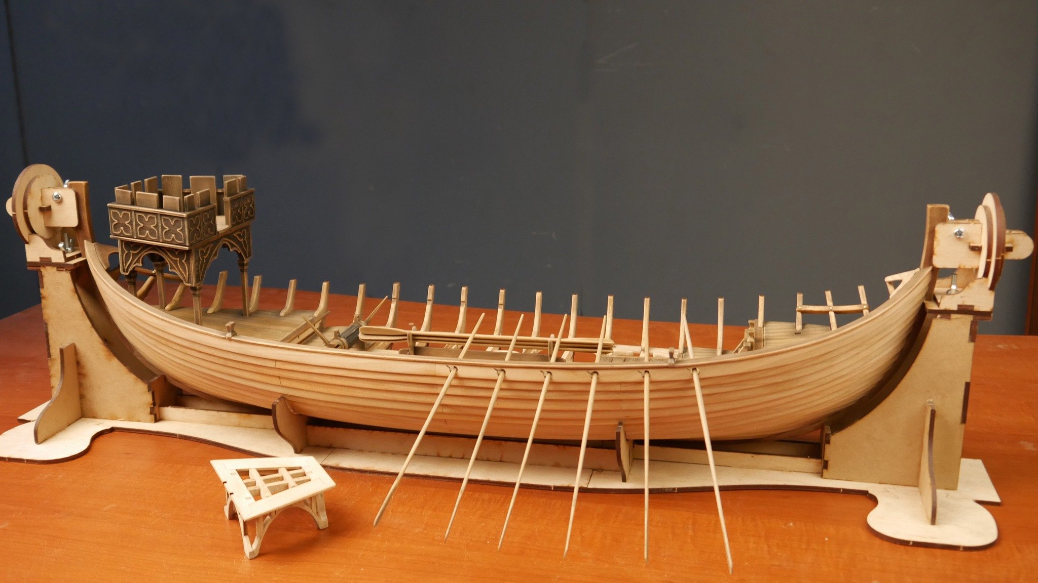
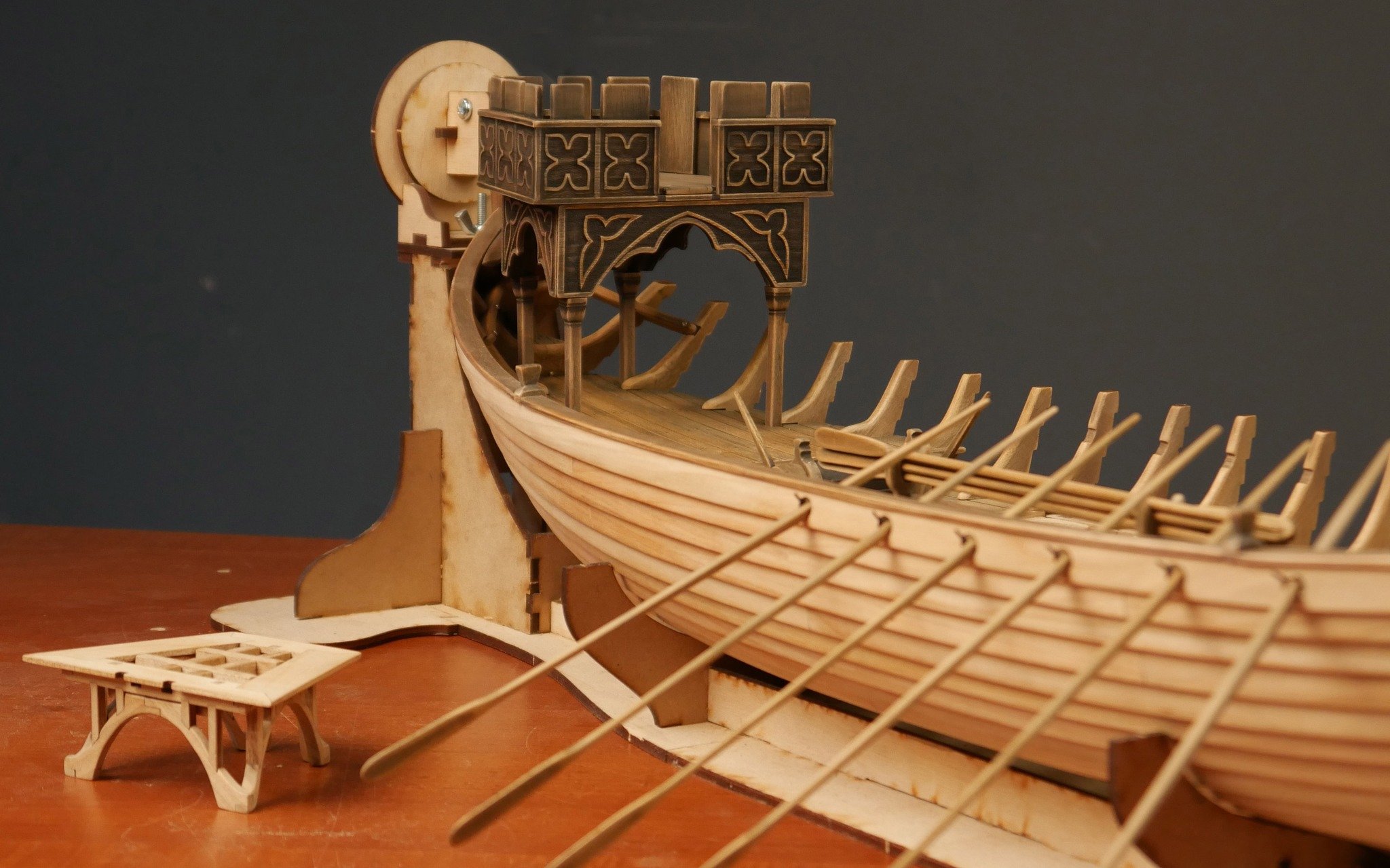
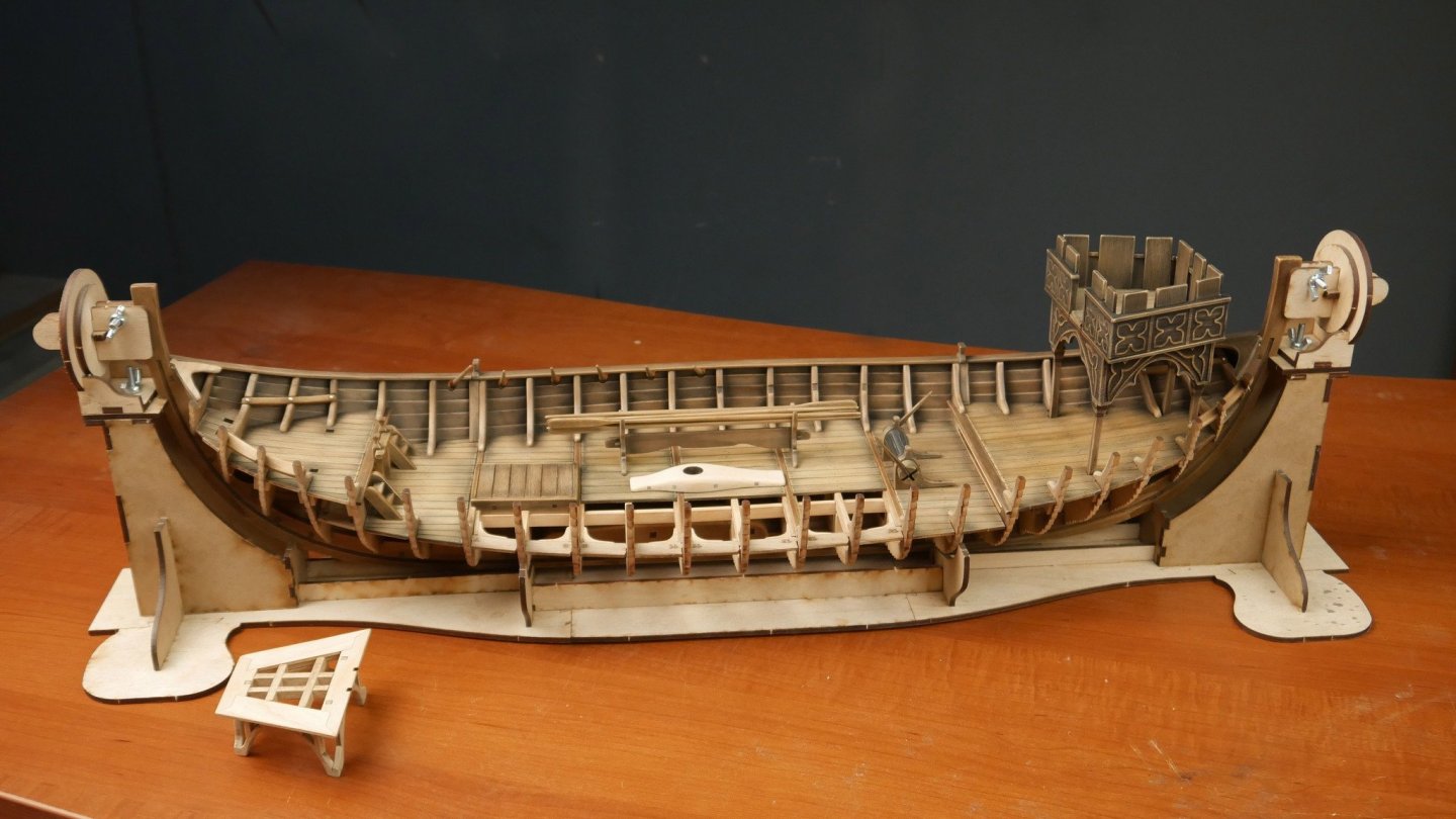
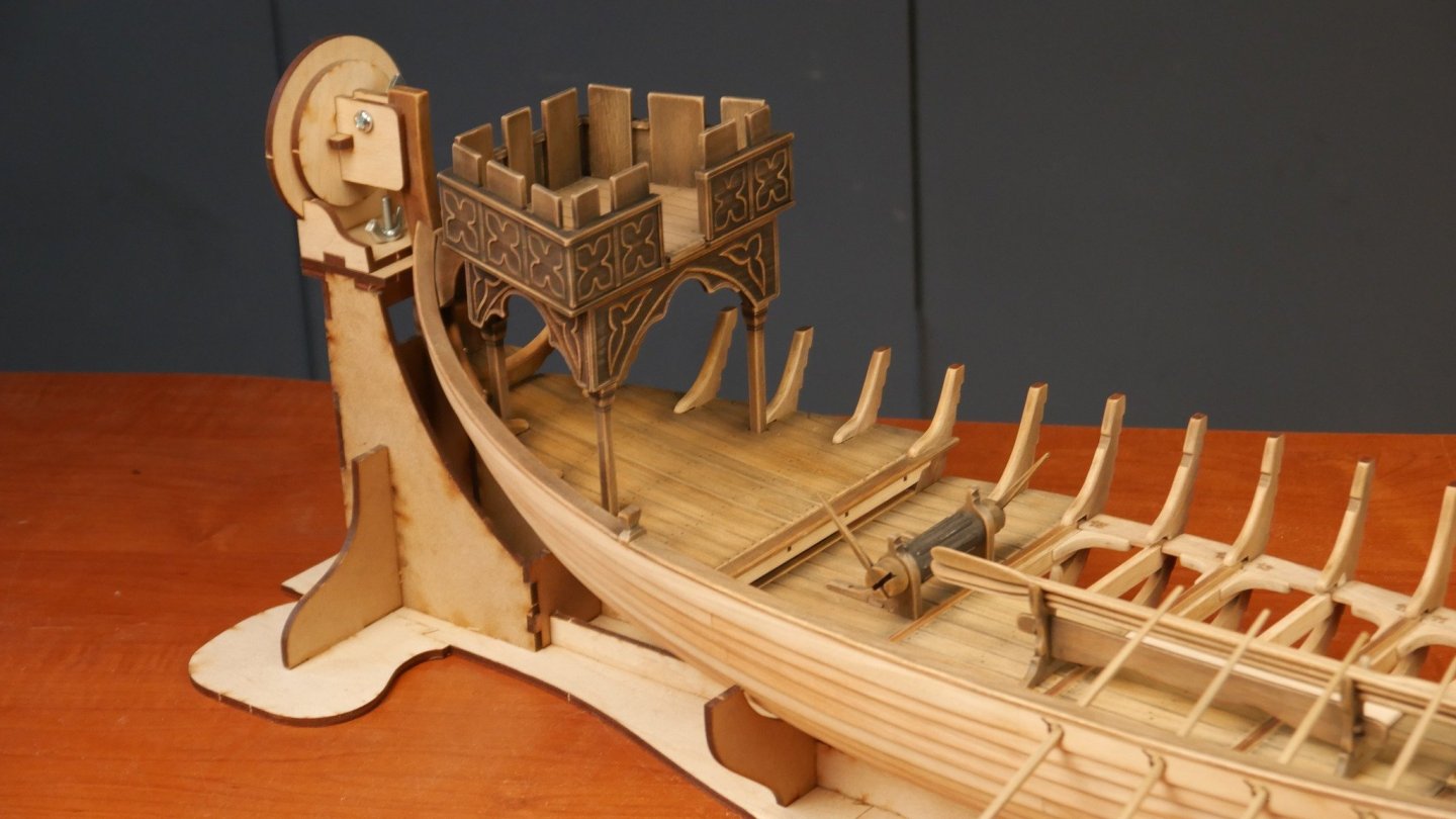
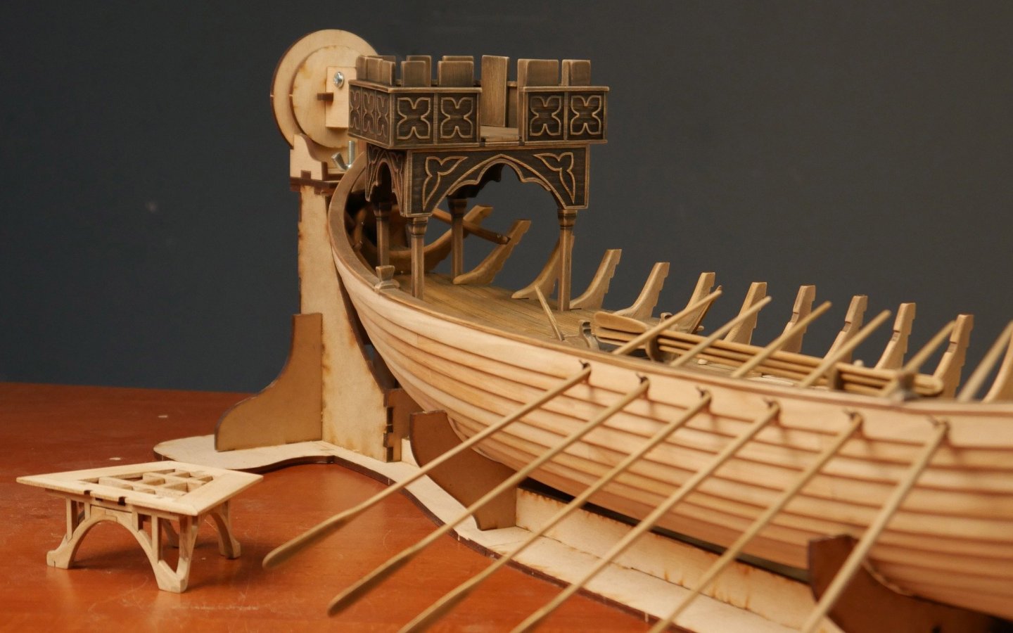
Oh, I do have a few more photos, showing one of the towers installed...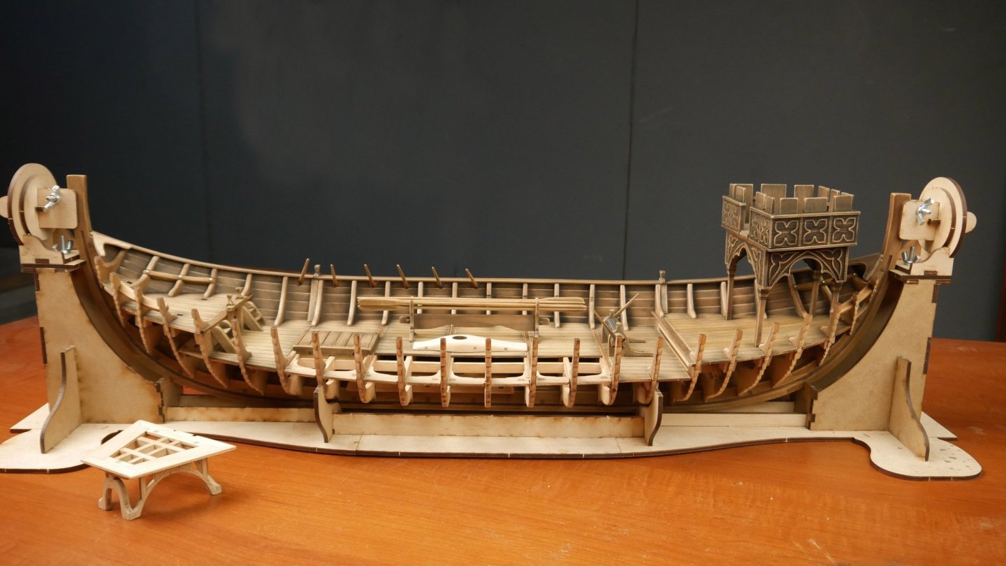


- 15 replies
-
- 14
-

-

-
- winchelsea
- medieval
- (and 1 more)
-
new kit alert! New kit on the horizon - Winchelsea Nef
James H replied to James H's topic in Wood ship model kits
Yes, the paint set is on the site. He has a YouTube video explaining how to achieve that look.- 15 replies
-
- 5
-
-

-
- winchelsea
- medieval
- (and 1 more)
-
new kit alert! New kit on the horizon - Winchelsea Nef
James H replied to James H's topic in Wood ship model kits
I haven't done any painting yet.- 15 replies
-
- 5
-
-
-
- winchelsea
- medieval
- (and 1 more)
-
new kit alert! New kit on the horizon - Winchelsea Nef
James H replied to James H's topic in Wood ship model kits
I've been sent a few more photos of the progress on the Nef. This looks so beautiful.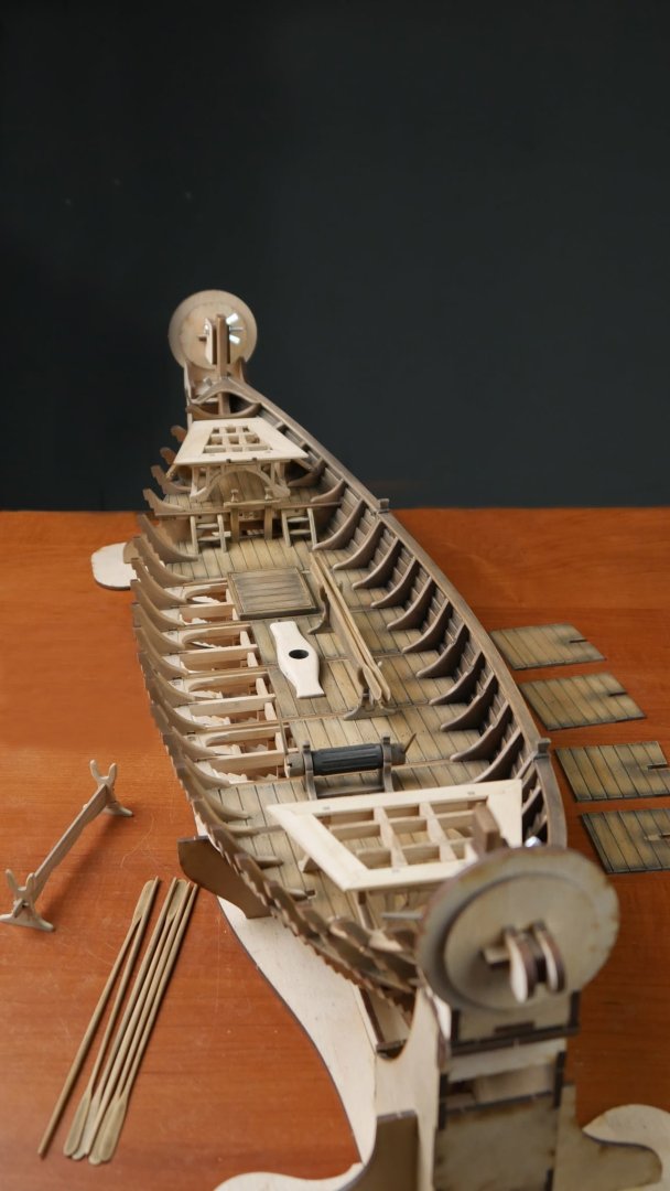


- 15 replies
-
- 12
-
-
- winchelsea
- medieval
- (and 1 more)
-
Not an 'introduction'. Moved to correct forum area.
-
If you are thinking go getting this kit, I just added the product to the Vanguard Models website for when the product is near. I'm sure Chris could tell you a little more about ETA.
-
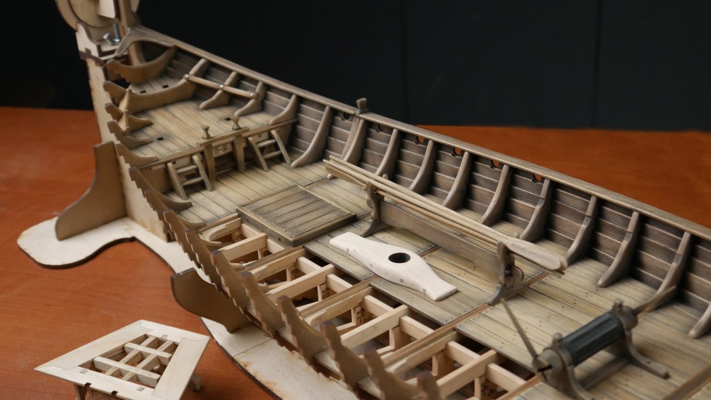
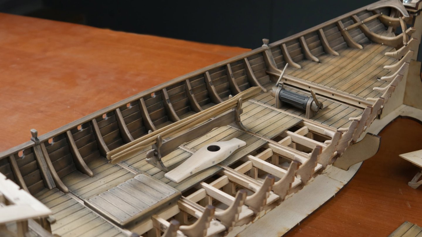
I do have to also add that the planks above deck level are properly cleaned up both inside and out, to remove any char and scorching that would impair the finish. All the others, as you can see deeper in the hull, are left as they are.
-
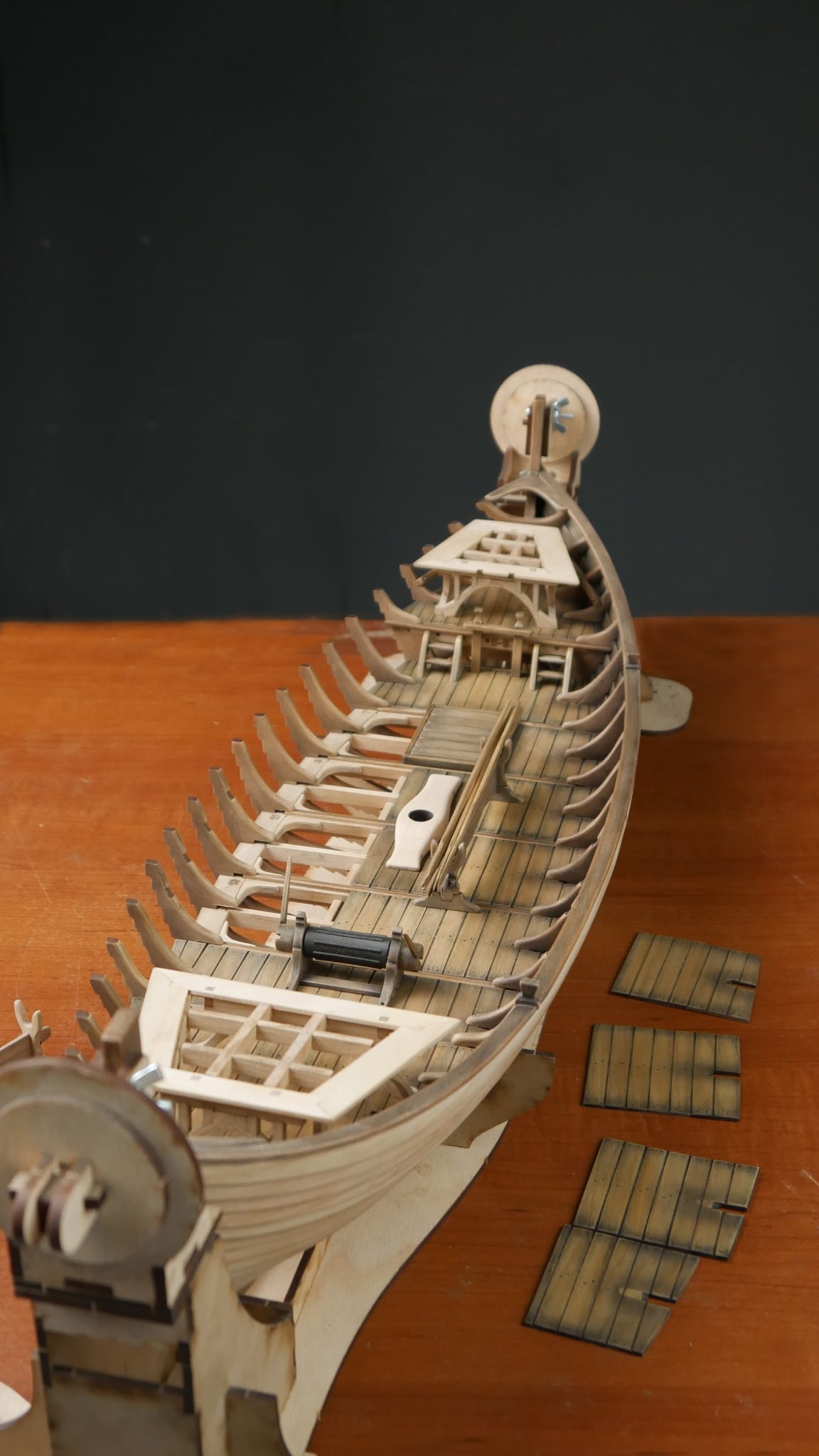
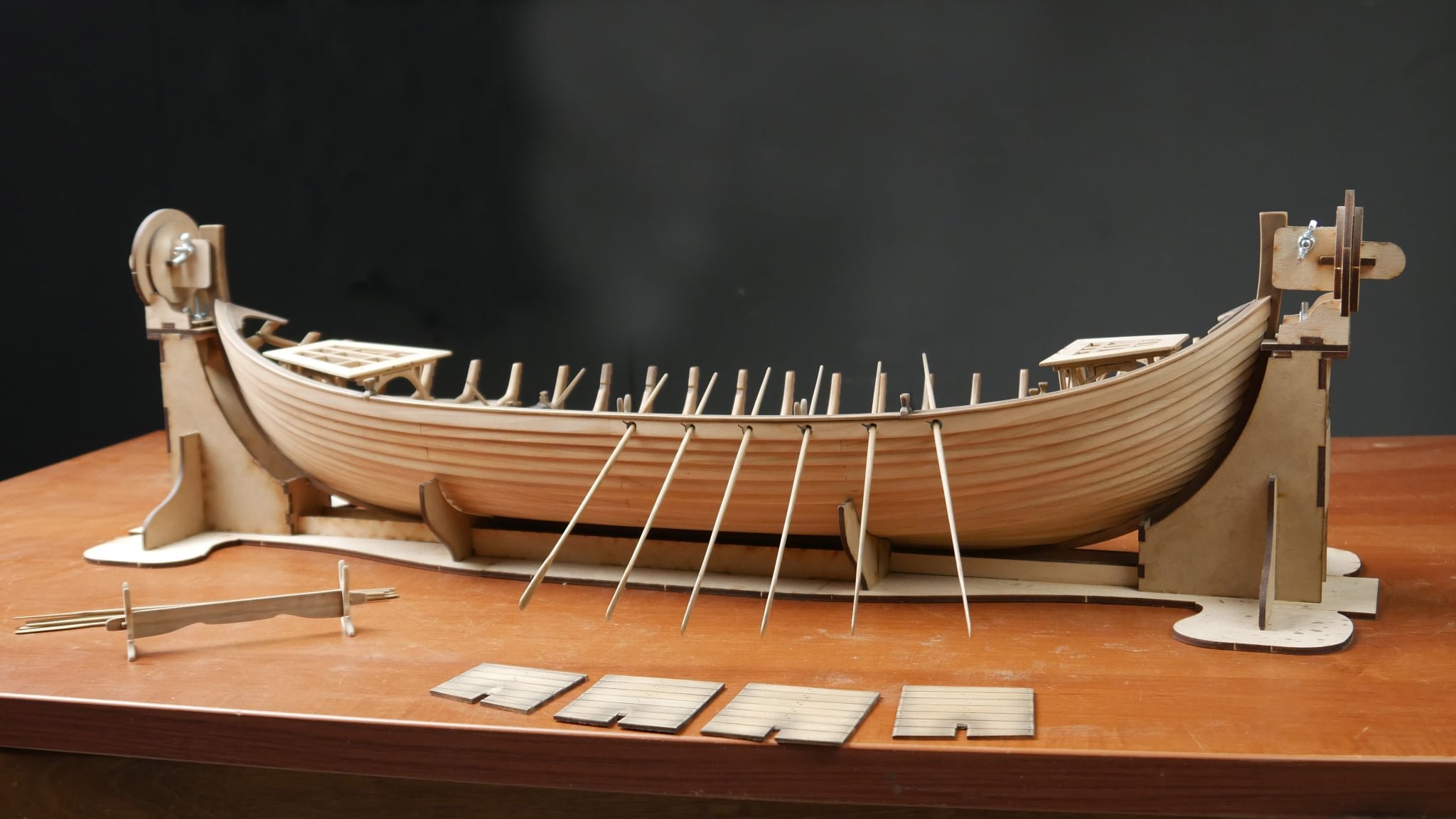
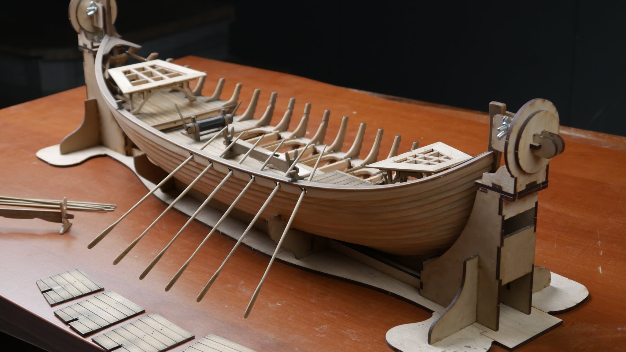
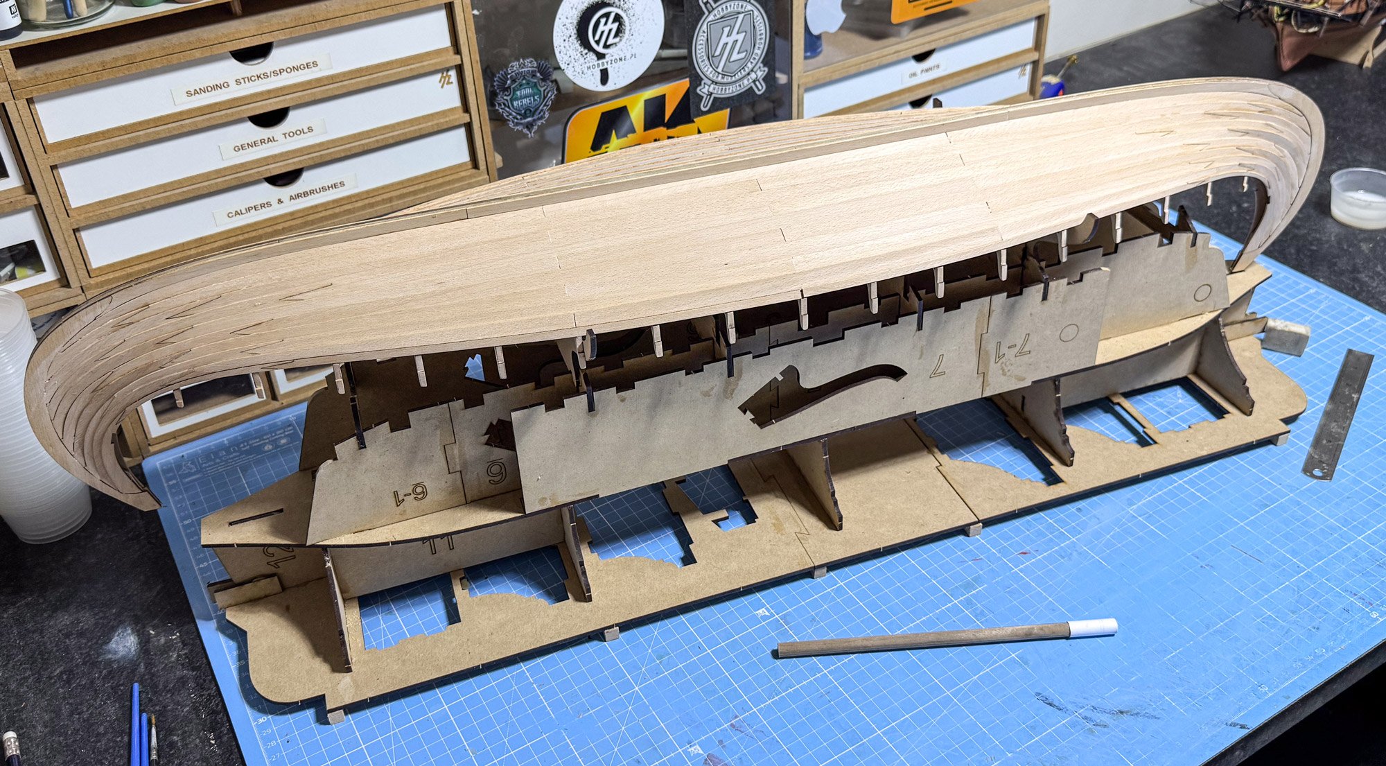
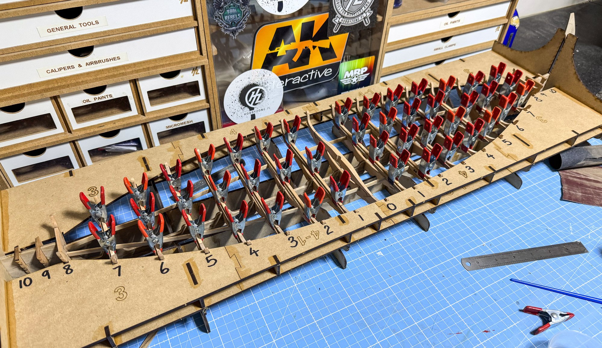
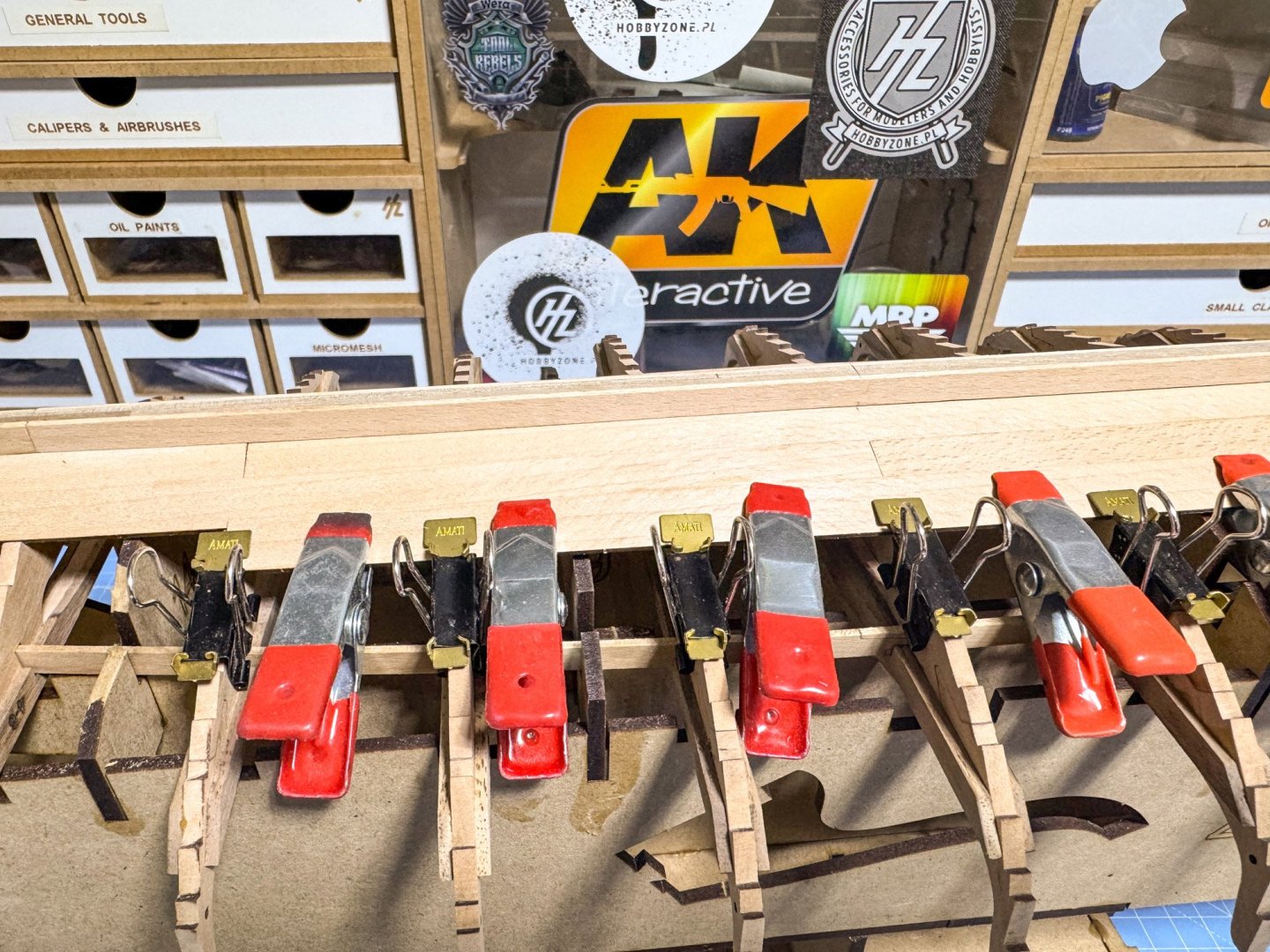
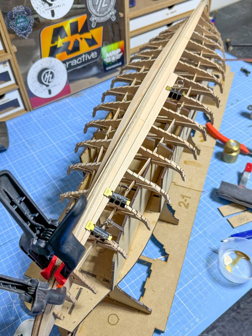
Planking is done!.....almost. You need to be real careful when planking. It's not a hard model to plank, and it's inevitable that you'll likely need to adjust the bevels a little. The planks are also supplied in a number of pieces each. What matters is first of all accurately fitting the temporary prow side facings. These will be key to making sure that each plank sits accurately on top of the other at the prow, and stack up to the correct height when it comes to the 10th row. That is, the last plank will sit neatly into the remaining gaps at the top of the temporary prow facings. Does that make sense? Ok, here we go. You can see here that the variation in the colour of those alder keel parts now doesn't matter. They are all covered up. You get an idea of how the sections are fitted, here. When it comes to working my way around the prow, I do multiple test fits and trims before I commit to glue. At that point, I only glue the prow too, then clamp. When set, I work my way around the bulkhead and use lots of clamps until fully set. This process isn't at all difficult, but it takes time to do methodically so that you get the best outcome. I'm not saying I did things perfect, but despite me being supercritical of my own work I'd give a generous 9/10. That is generally due to Pavel's excellent design being closely followed, especially on the tutorial videos on YouTube. Here is the hull, planked up to the 10th plank. At this point, I ran all the way around the exposed deck beams/ears and softened the edges. I should've done that before building the hull frame, but it wasn't difficult to do. You will notice one mistake I made.....the furthest bulkhead with ears....the infill part has the part number facing inwards, meaning it'd be seen when the model is complete. I'll come up with something to hide that. I put them in that way to neutralise the kerf between the bulkhead and infill, so my mistake! Here's the obligatory underside shot. You can clearly see where planks have been kerf-jointed so the grain runs true to the plank flow. I did have one joint 'pop' when planking, but that was only because I snagged it and strained the joint. There are just two more planking runs to fit, but these won't be fitted until I start to add stain to the interior. The reason is that it won't be easy to add the various stages to the stain if those planks are running between the bulkhead ears. In the meantime, I might make up the floor sections and do some test fitting before planking is finalised. Until next time...


- 48 replies
-
- 16
-
-
-
Just a quick note. Fritzlindsay is another account that Allanyed set up after his banishment from here last year. He's now been restricted from posting.
- 332 replies
-
- 3
-
-
- Harpy
- Vanguard Models
- (and 1 more)
-
I always found that if I was getting bogged down on something, I'd work on something else and then I can return to the previous project with a fresh mind. Maybe aim to finish Bounty, then do Vic? Or maybe just do Victory if you feel you have the skills to do that.
-
I hope you'll do a build log for us!
-
I wouldn't say this is a beginner kit. If you're careful and a stickler for measuring 10 times and gluing once, then you should be good. Just dry fit and adjust any bulkhead bevel as you see fit....move slowly, and you should be ok. It's only the planking that tells me you need a little experience. The rest is quite straightforward.
-
This is a difficult one that has hit us a couple of times over the years, and just seems to clear up. Please check this topic:
-
Not just a makeover, totally built from the ground upwards. You won't believe the work involved in keeping the old site online, and then the constant battles with flaky software etc. It wasn't viable, so good riddance to it!! A million % improvement!!
-
This is how I do it.

-
In that case, you'll always be waiting to see what improvements are made, while never allowing yourself to actually buy it, in case more improvements are made Thanks for the comments. It's a lovely model to build. I'm currently assembling plank runs in between learning guitar.Two full strakes are on each side now and I've just made planks 3 and 4 for both sides, and waiting for glue to dry.
-
As far as I'm aware, it's only the oars which will change as these were originally being designed for the Nef kit.
-
Damn, I'm so sorry to hear that. I hope all goes well for her and you both. Family is more important than anything else.
- 241 replies
-
- 1
-
-
- Vanguarrd Models
- Harpy
- (and 1 more)
-
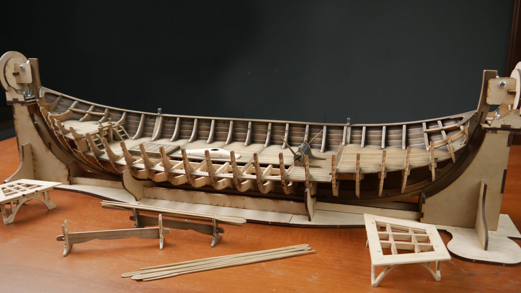
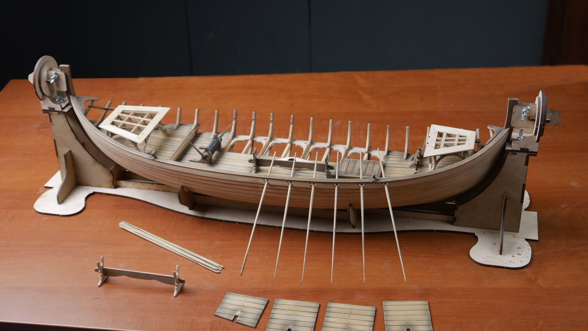
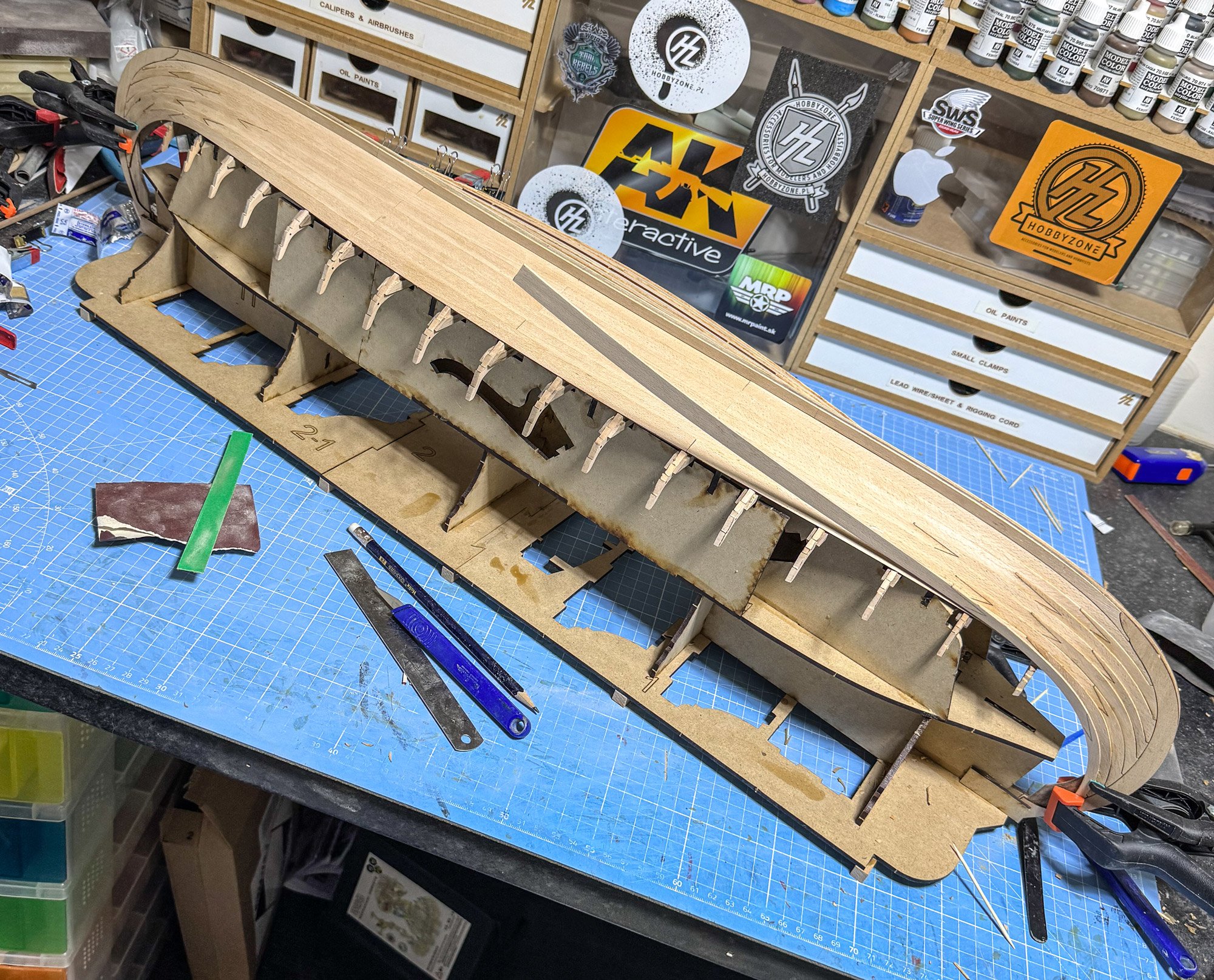
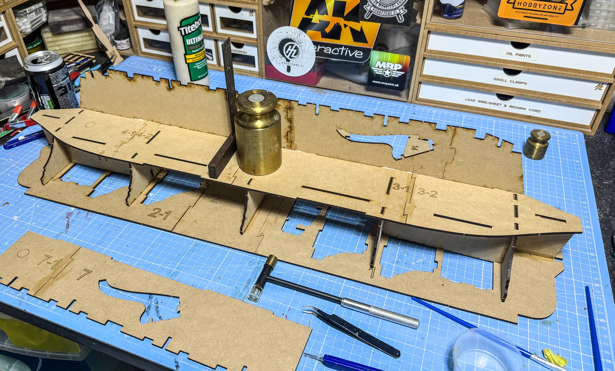
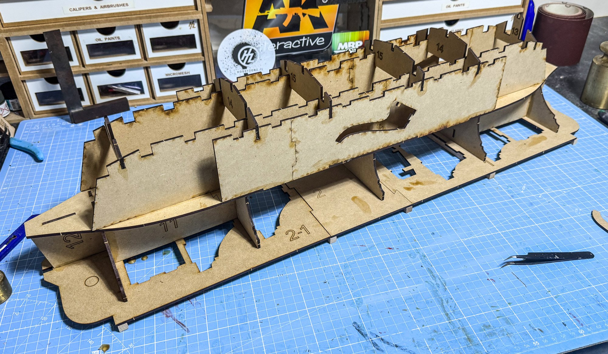
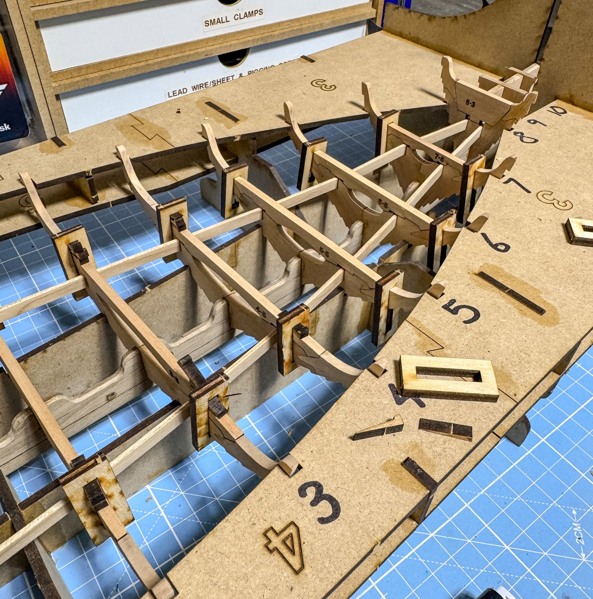
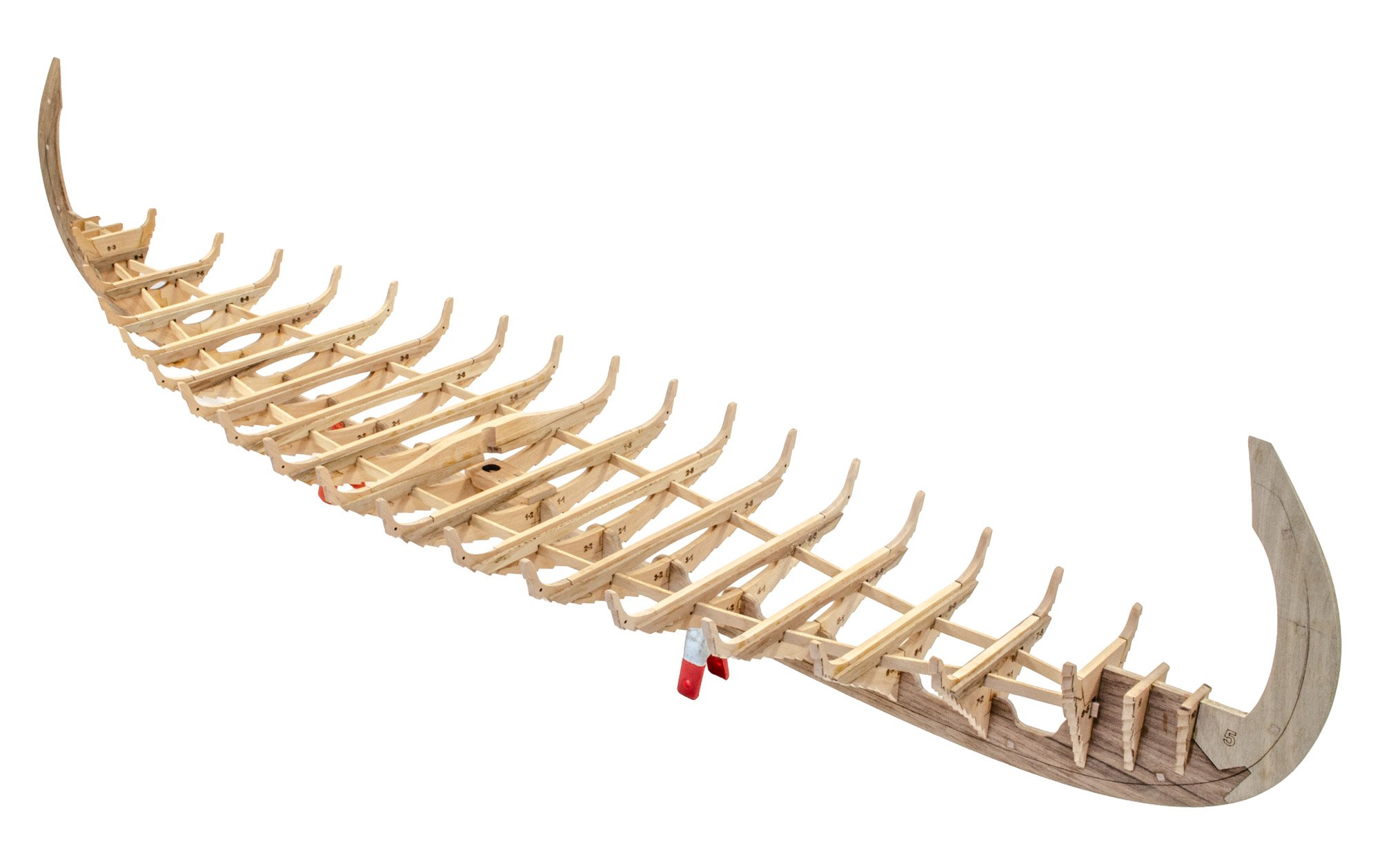
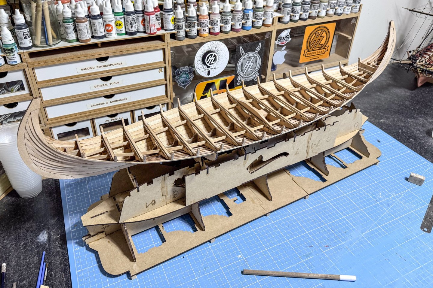
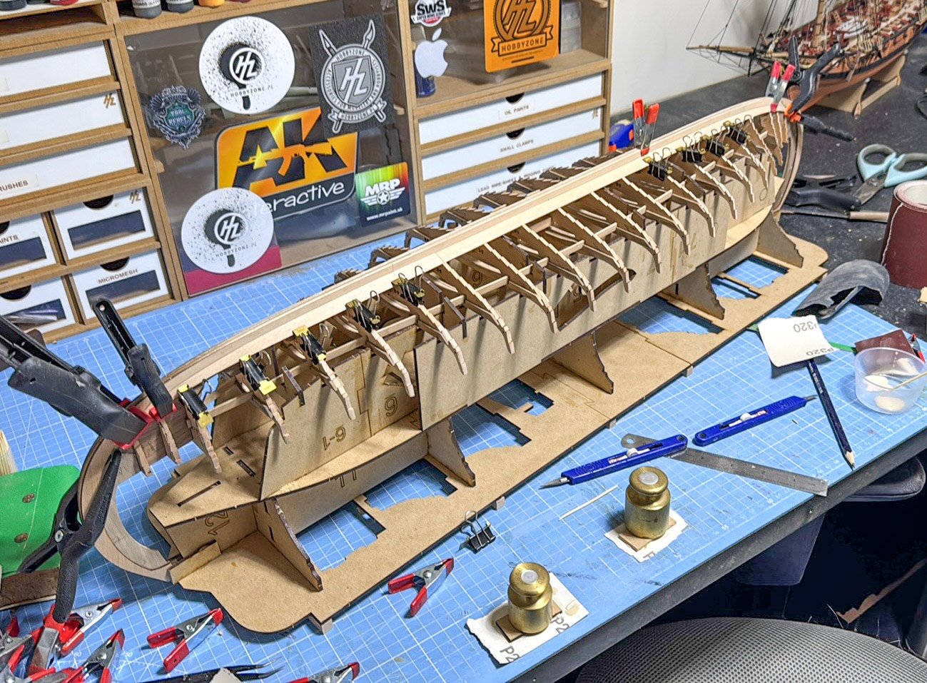
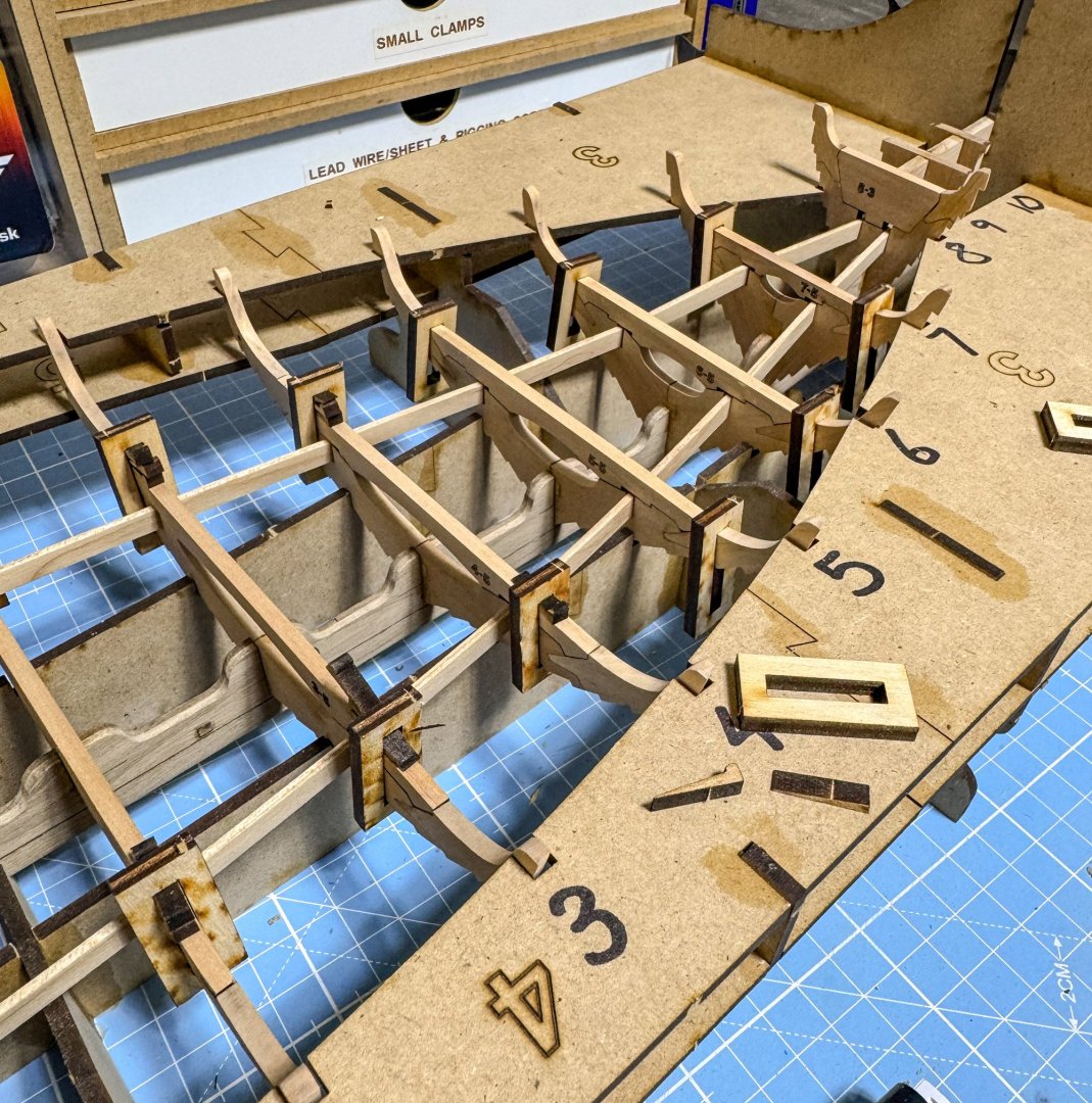
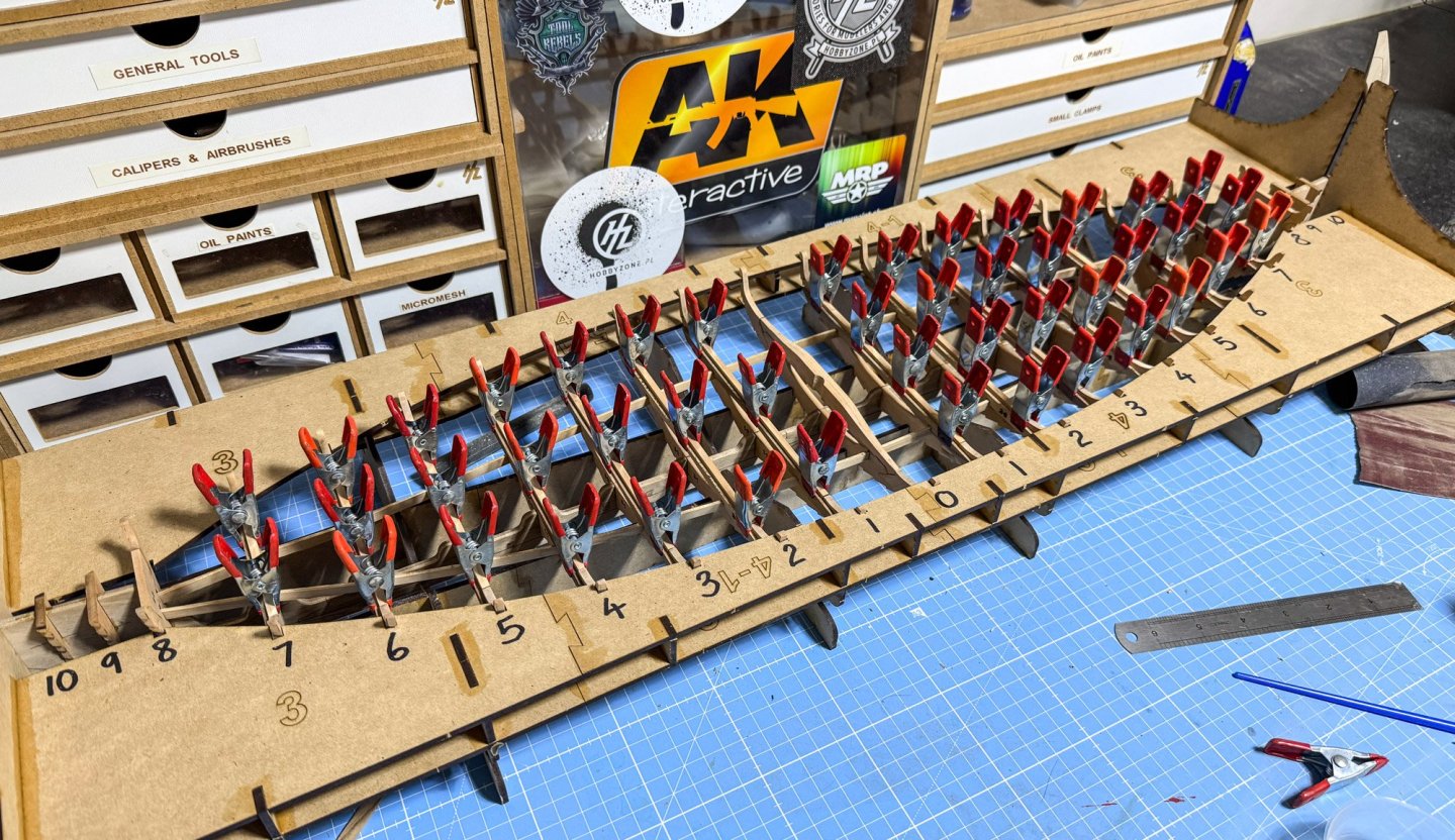
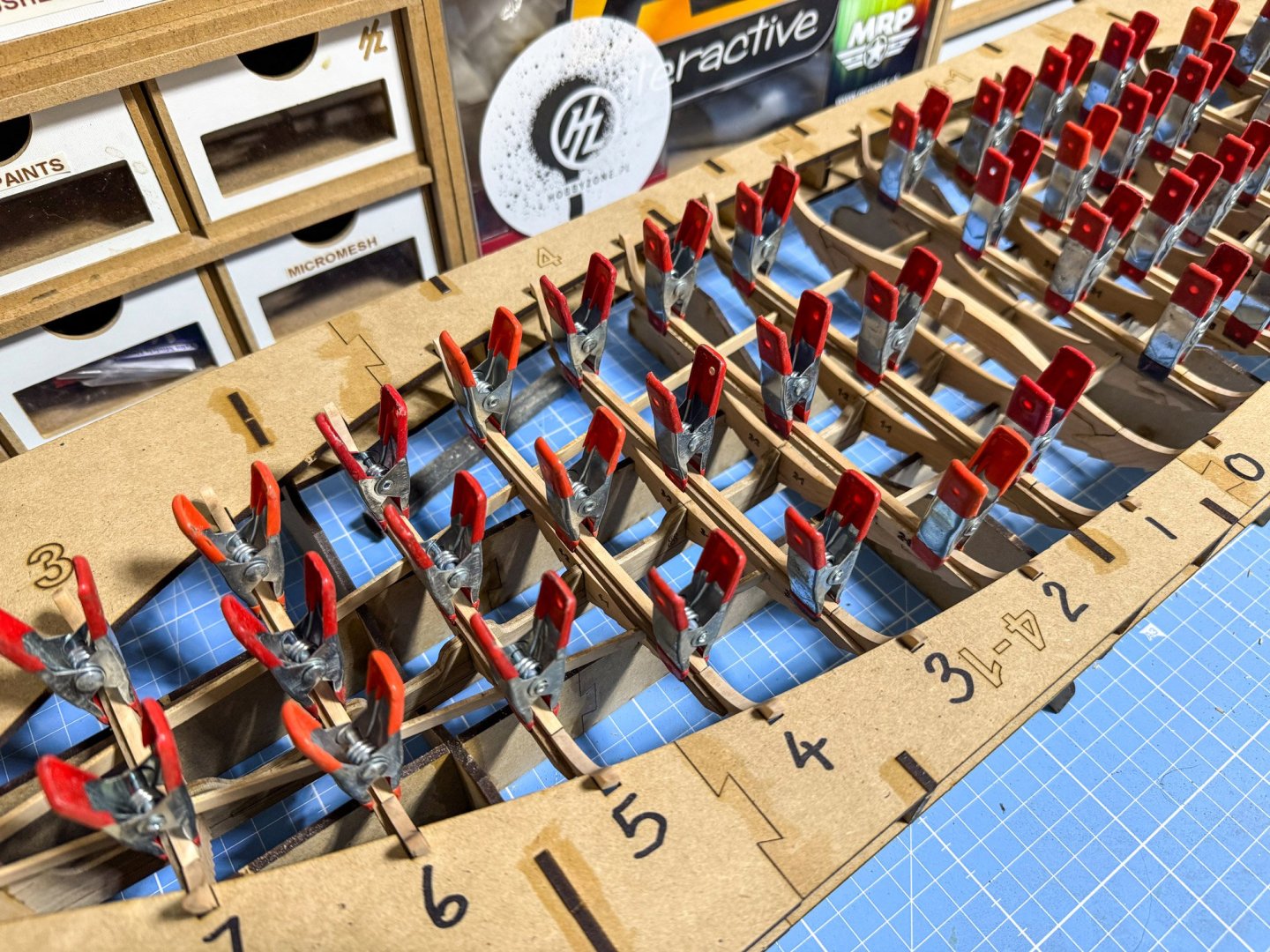
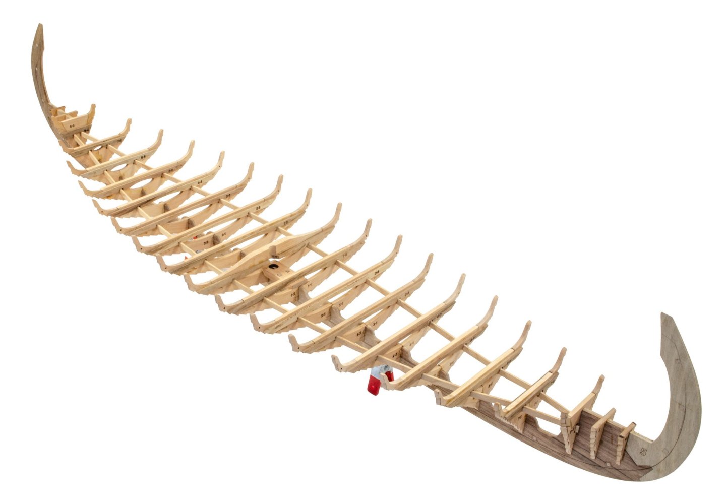
I did say there was another jig to build, and this one takes up 8 sheets of MDF. There's more in work involved with this one too, and just make sure everything is absolutely flat when assembling it. To help, I used a 1kg weight to hold things down when installing the various assembled plates. An engineers square also comes in very handy. This shows the hull turned upside down as a test. What I did need to do at this point was to fit those temporary prow/stem doublers as they not just protect those thinned and vulnerable places, but they also help align the hull properly. To aid this, I added a couple of pieces of spare MDF to hold the prow/stems at that point. You can see these in the third photo down from here. The first plank is applied after sheathing the keel sides in beech. This creates a nice uniform colour to the mix'n match colour of the alder keel. The first plank is supplied in 3 sections. The middle section is fitted first. Now the outboard sections are fitted, to the ends first and then trimmed to the middle plank. Then it's onto the second plank, supplied in four sections. I'll do another update when the hull is planked.


- 48 replies
-
- 11
-
-
I've never seen the Billings up close but know that it can be difficult to build, plus the planks are ply. There are some very nice renditions of it though, and I'd be proud to have built a number of them. Pavel's V2 looked like the ultimate at the time, but this has lots of clever quirks, a much better design, and of course those extras like resin viking and galley. Vanguard Models will have a number of these in a few weeks, and I hope we see a few more build logs here.
-
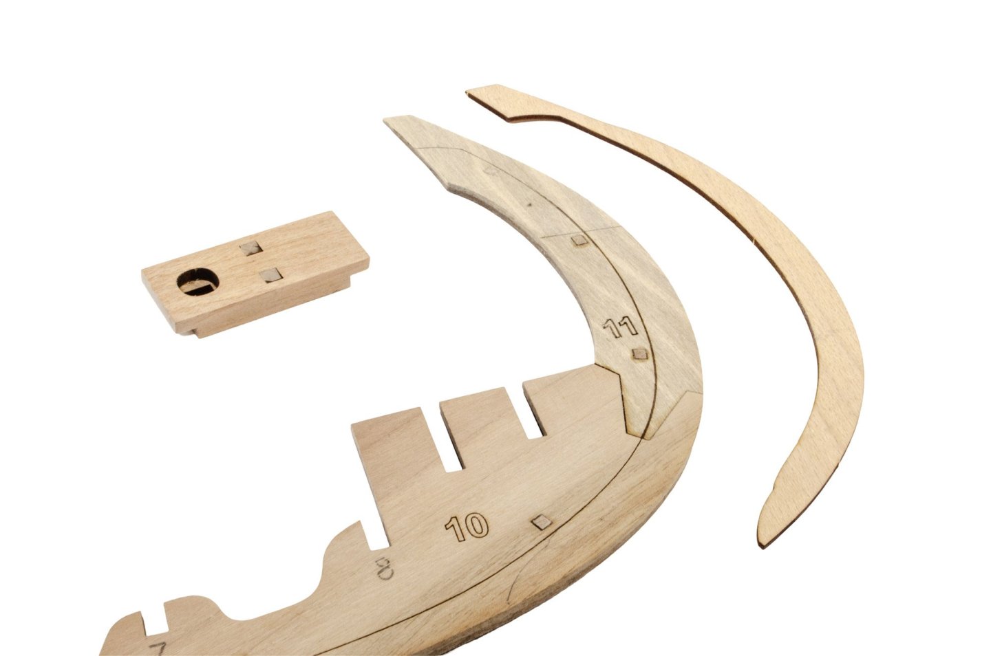
They are very different. Entirely. This is my review of the V2: Look at the parts shapes etc. Compare that with the V3: The V2 isn't available now, so any purchase will be the V3.
-
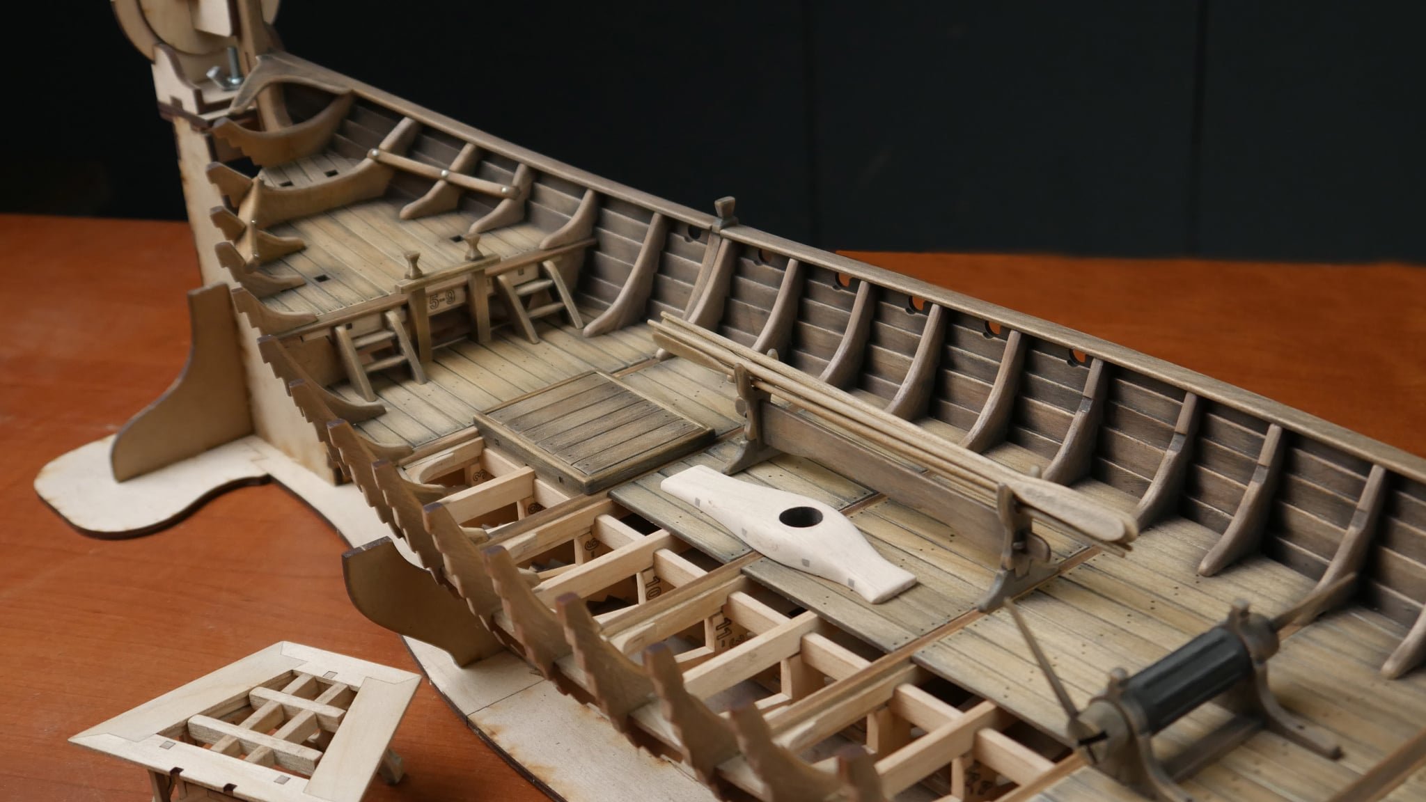
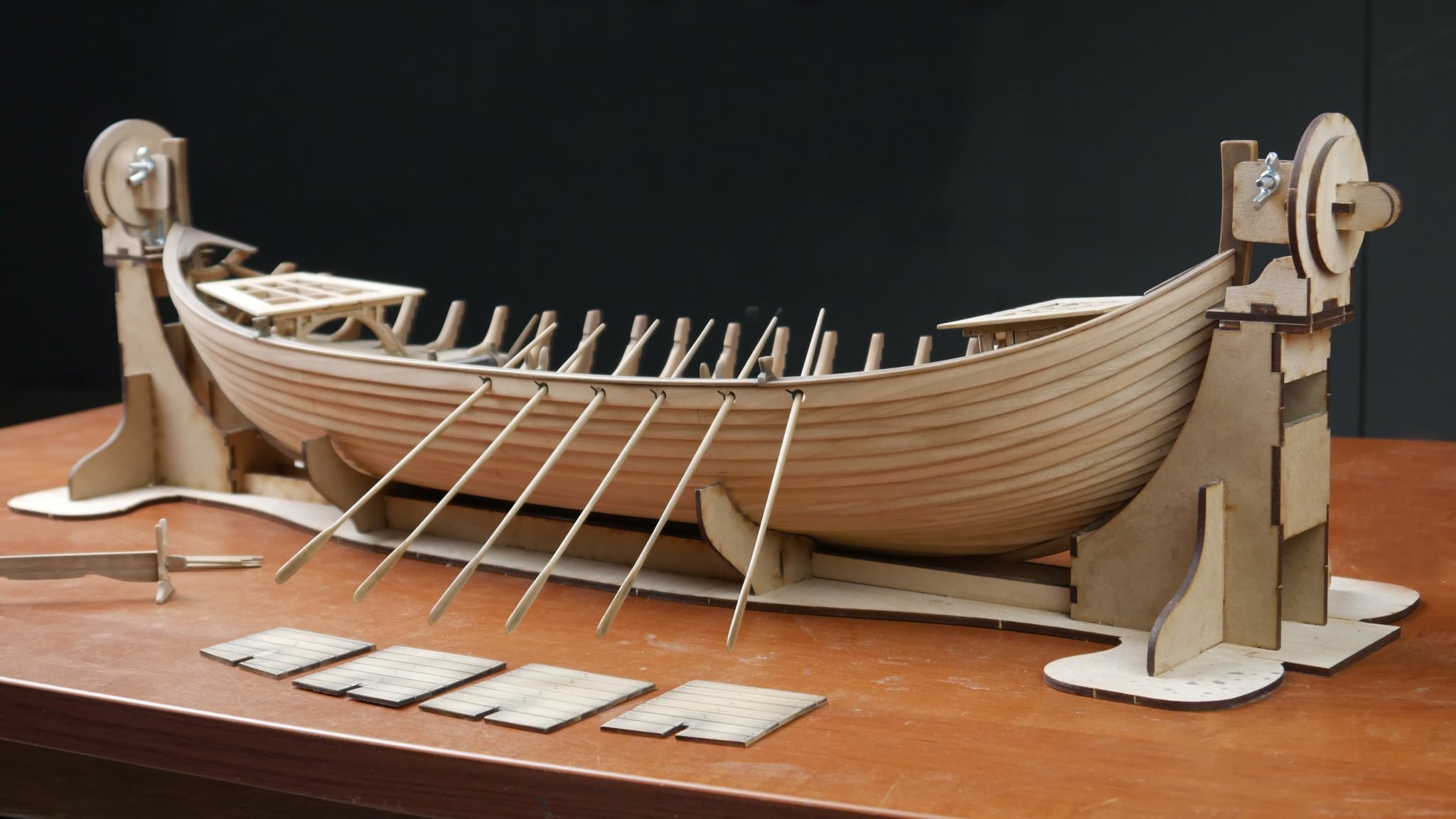
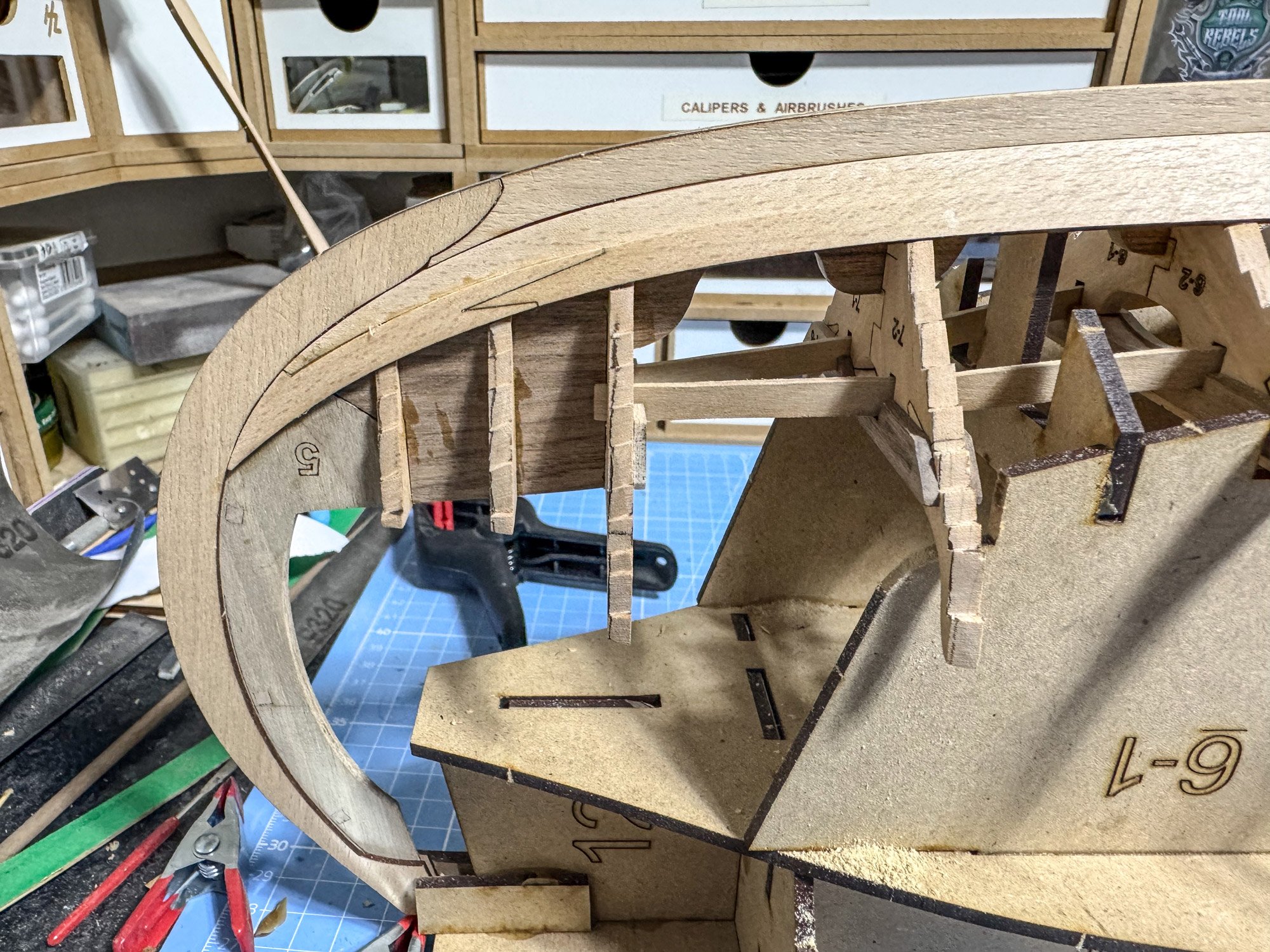
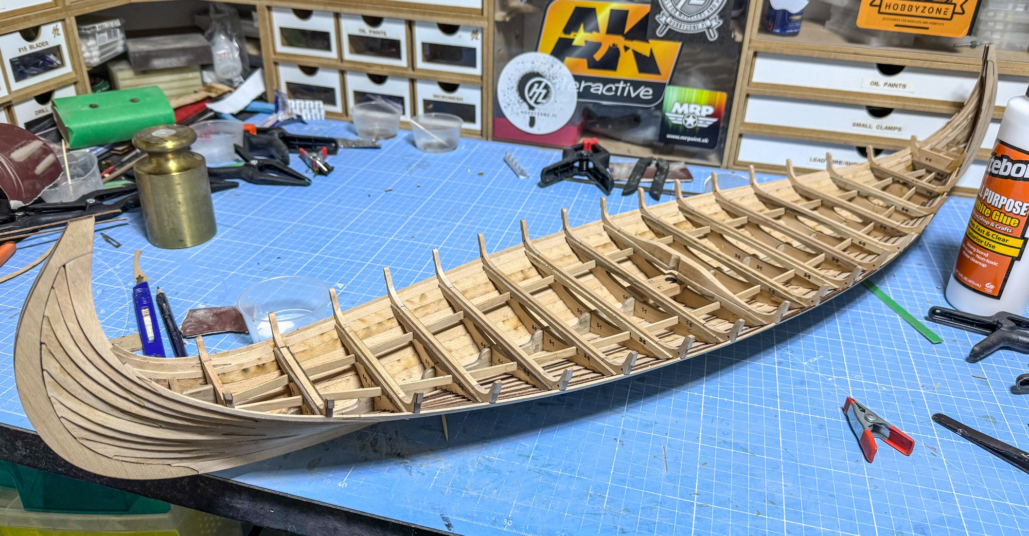
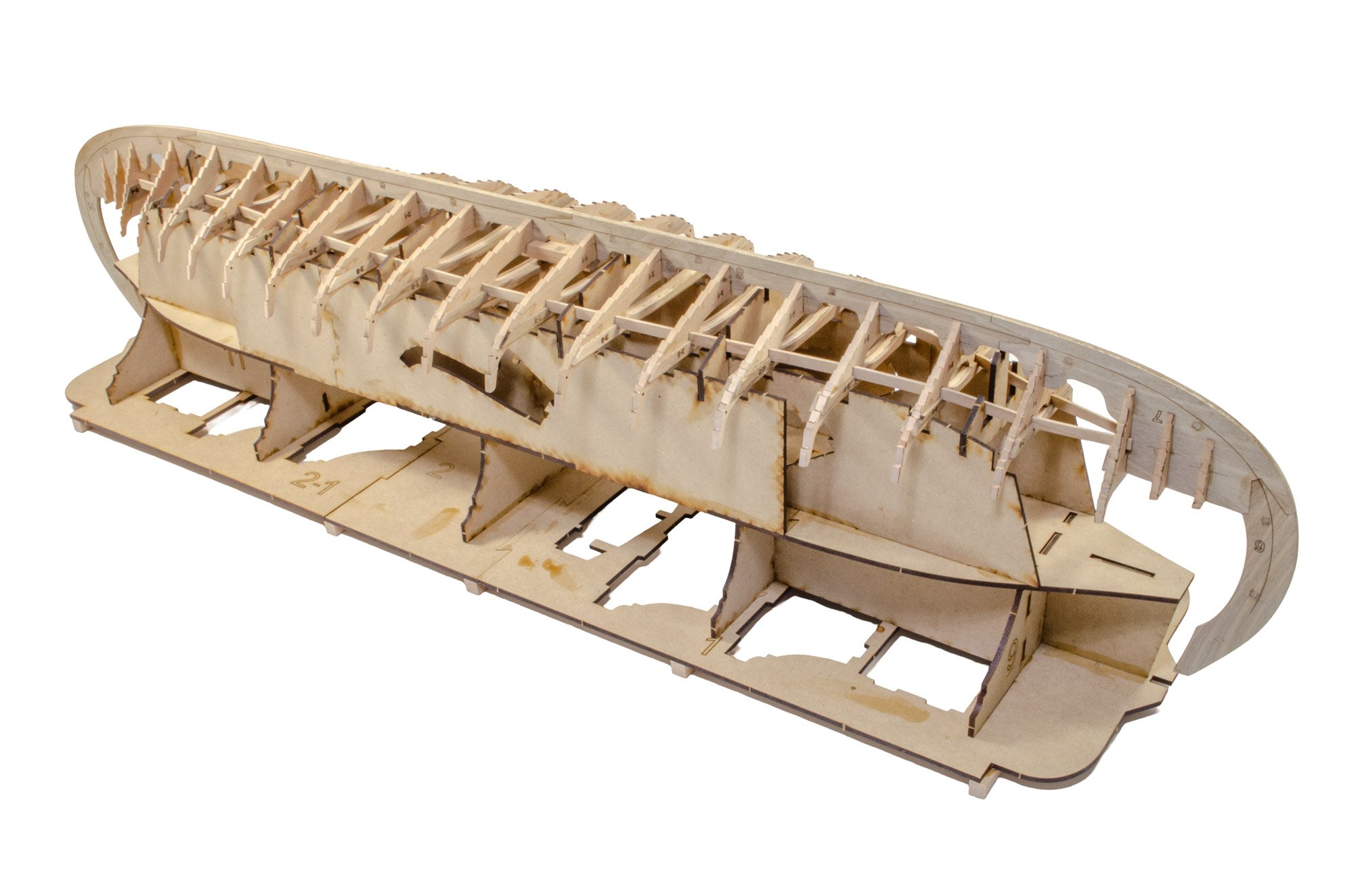
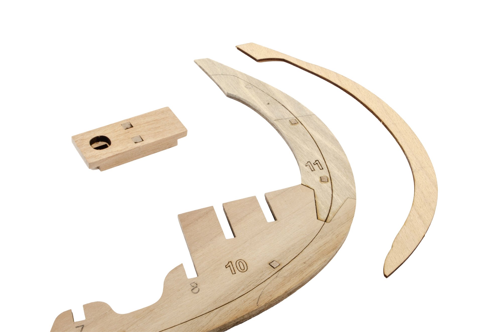
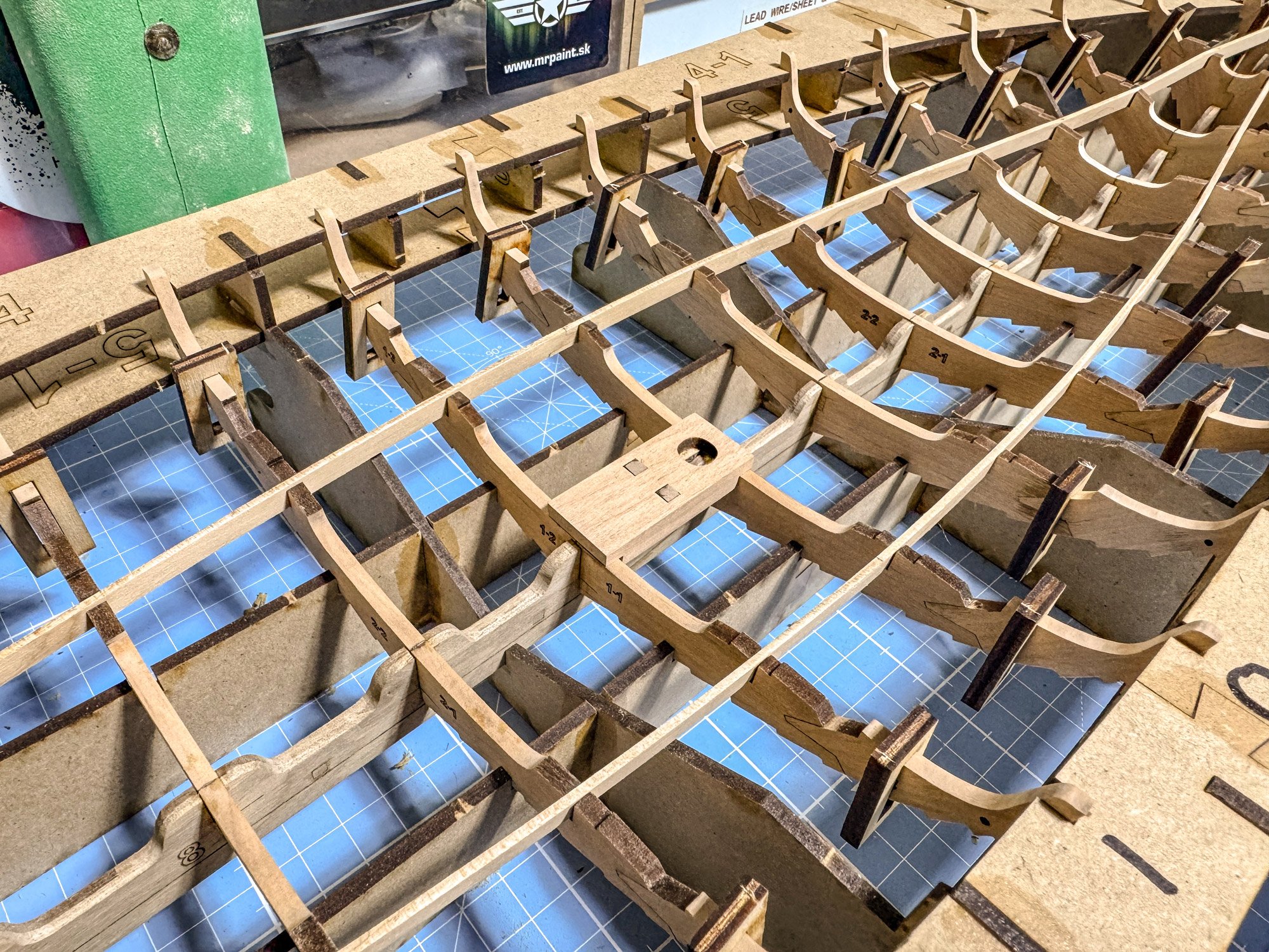
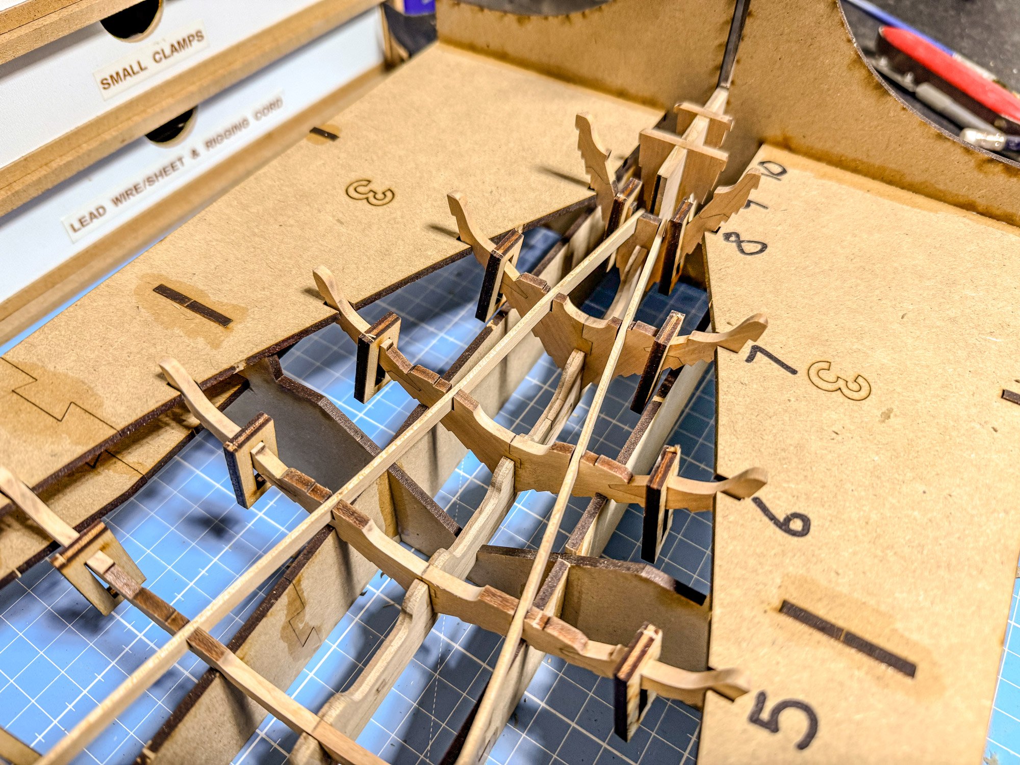
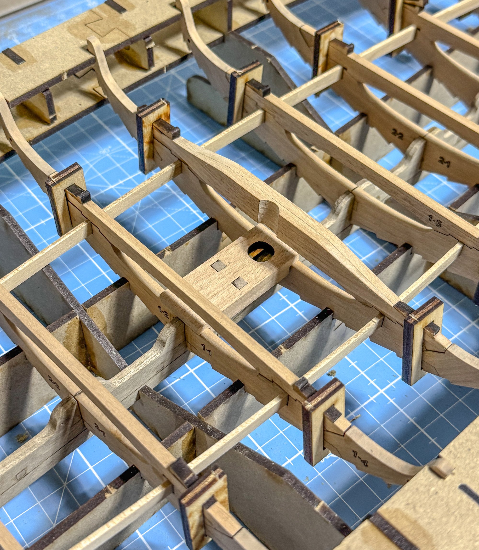
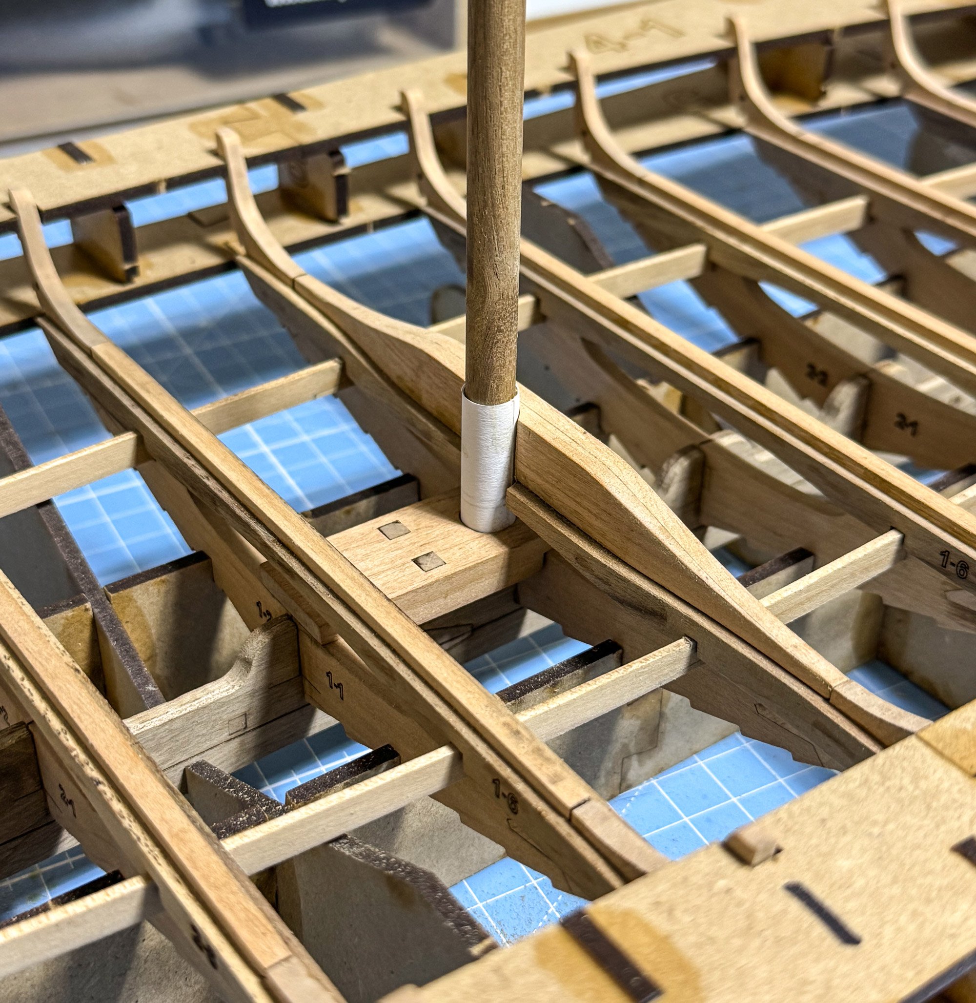
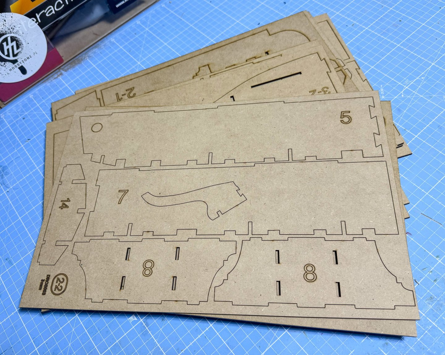
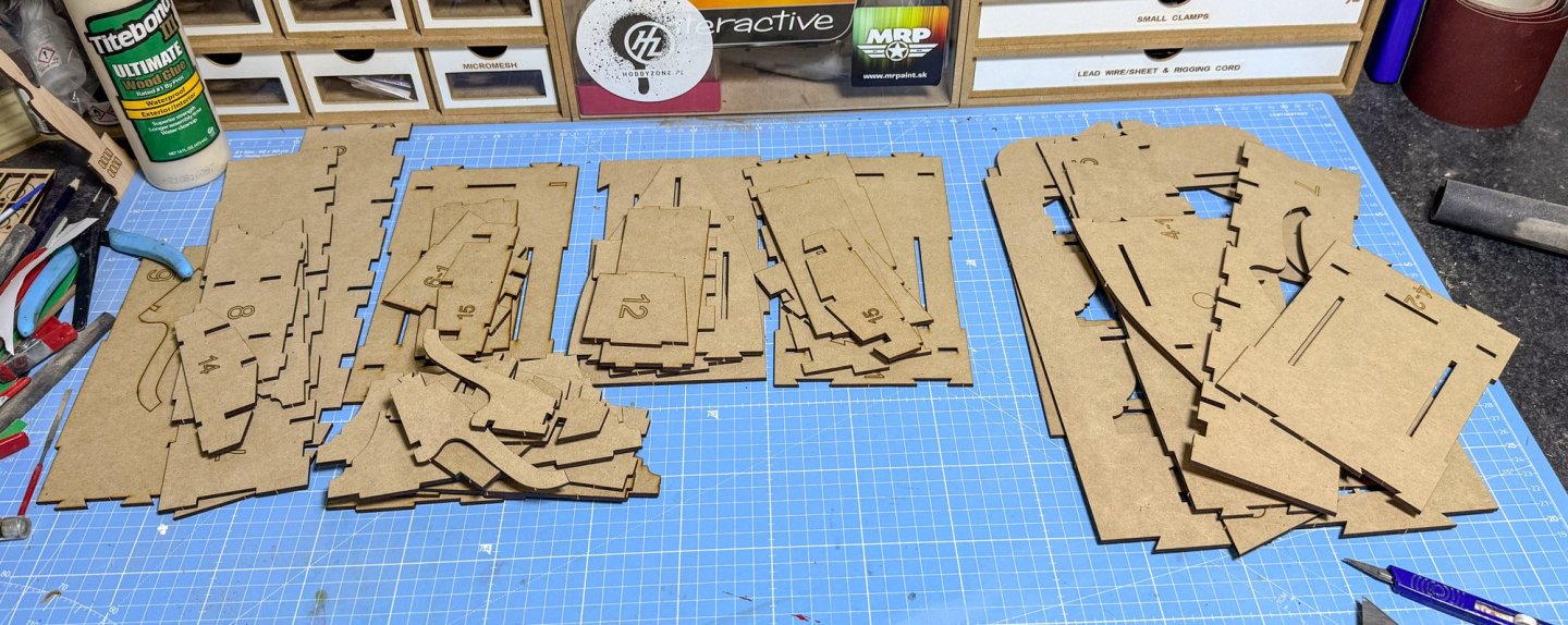
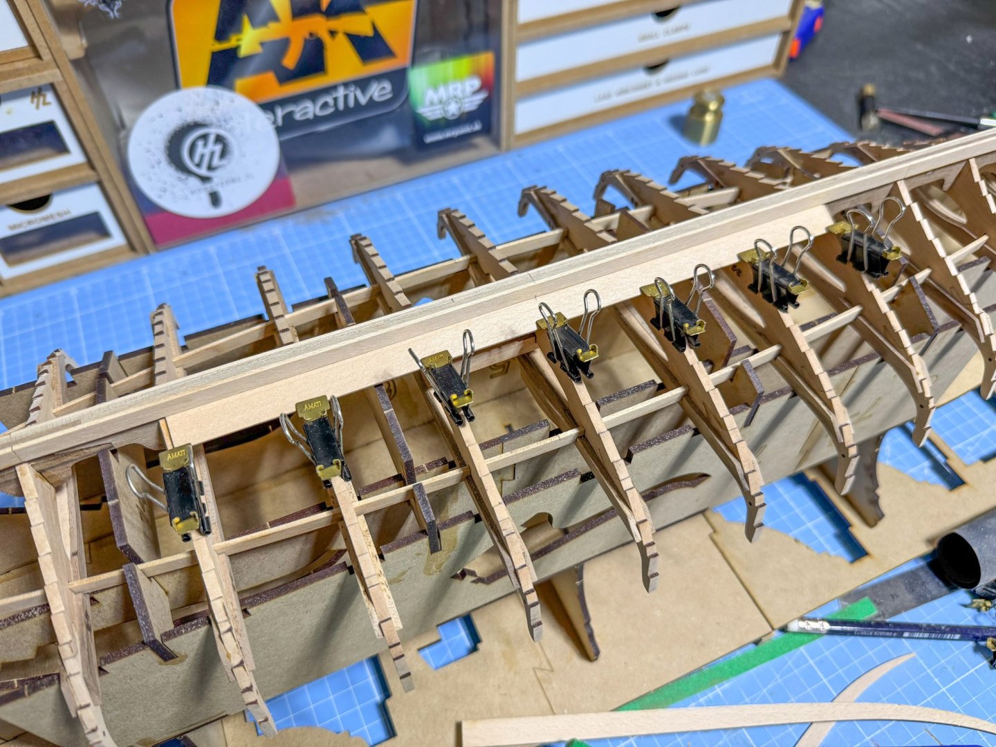
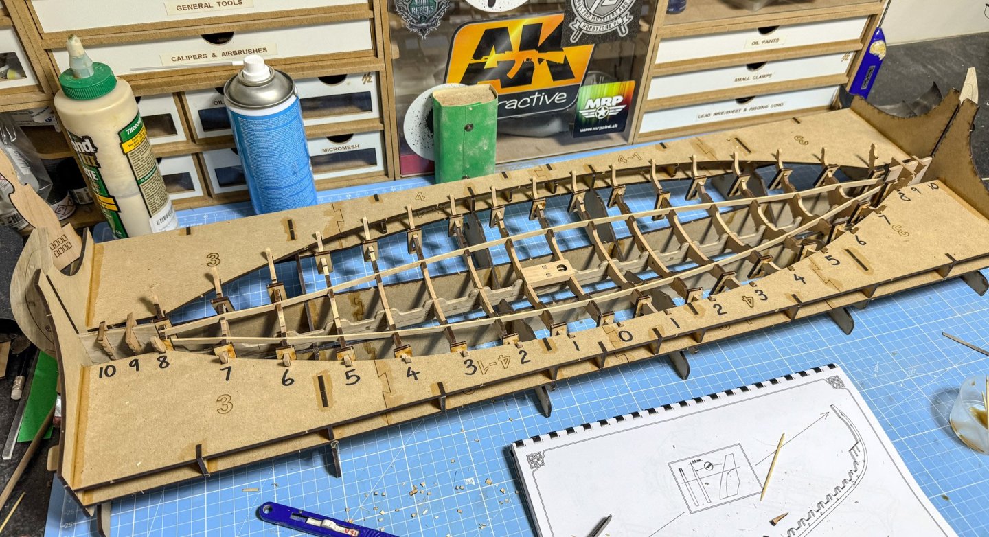
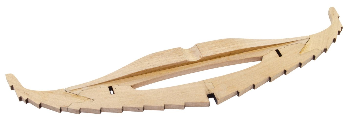
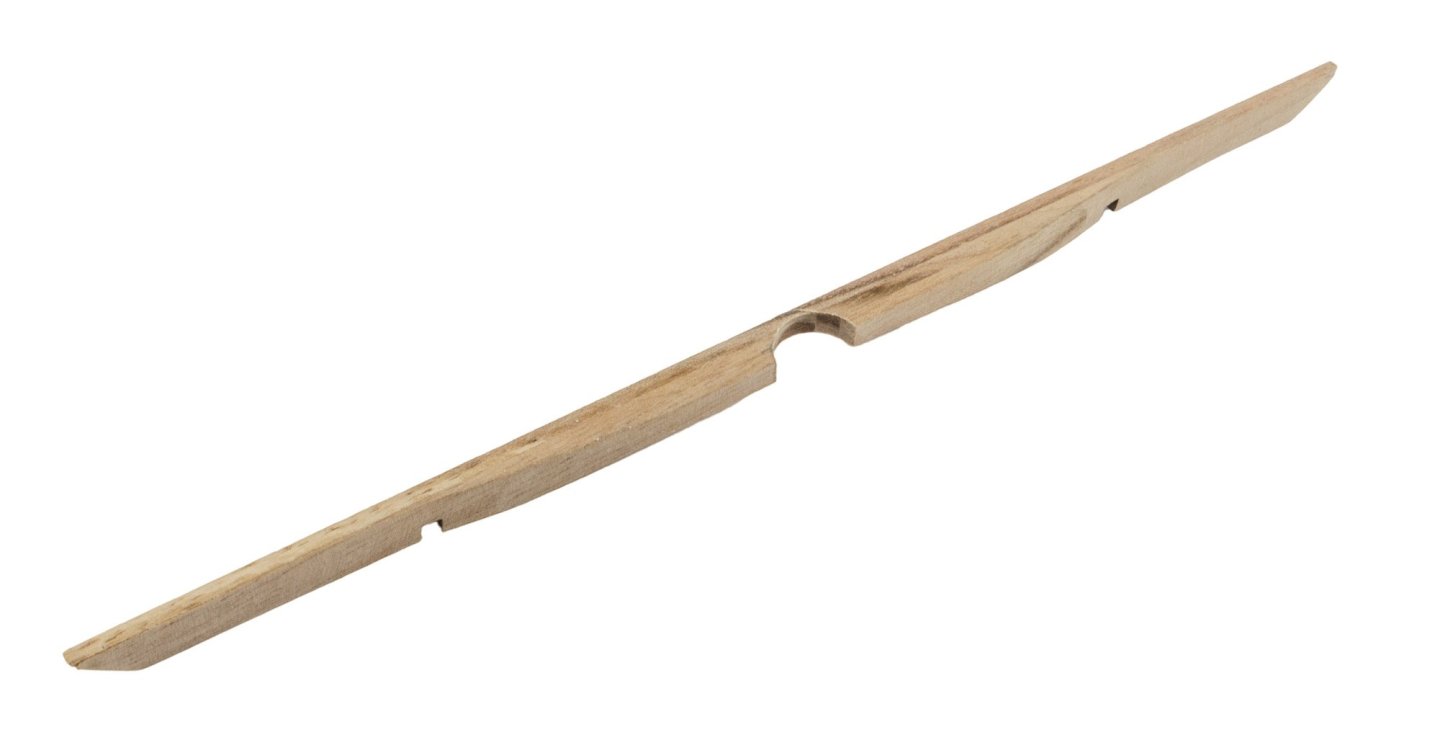
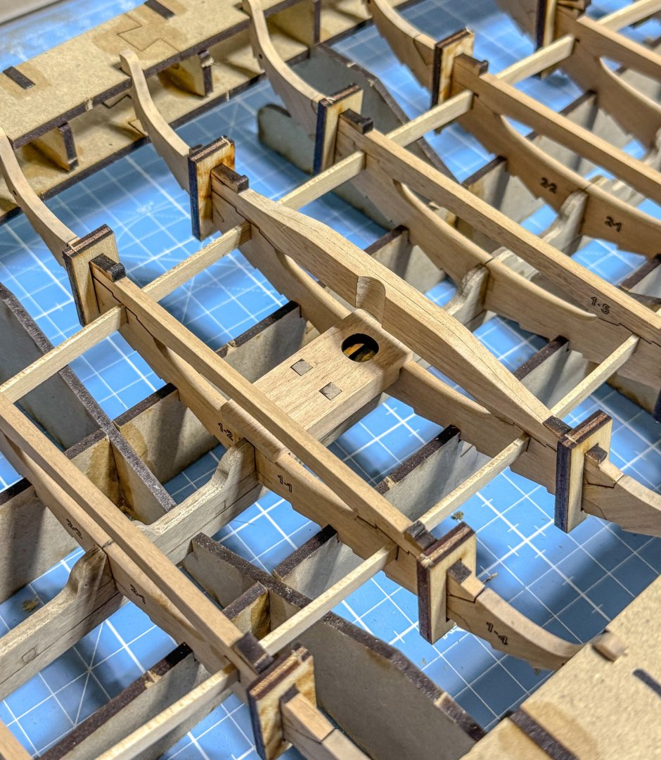
I have had to use my cutting mat photos here as it's difficult to get that huge jig into my photo area at the moment, but I have done some detail shots in my usual; style. Work resumed by thinning the top of each keel end. In the manual, this is supposed to be only 20mm down from the top edge, but the videos for this show it to be 60mm, meaning that the top of the prow and stern will taper in nicely to incorporate the carved head design. I wasn't supposed to do this at this stage, but it would be harder to taper these areas when the bulkheads were fitted. I tool the risk and it was fine. Here you see the mast foot assembly and also a temporary double for the thinned areas. I didn't fit these just yet. The keel is first slotted into the jog and before the two-part longerons are inserted to the bulkhead slots, an MDF 'clamp' is slotted onto each side of the bulkhead. All the bulkheads are now glued into place, and the longerons are inserted. I didn't glue the longerons themselves as I felt some lateral flexibility would be useful when the model is placed in the next jog for planking. Two photos here show the mast foot in place, but it's only a temporary fit. Here you can now see the clamps being used in conjunction with the small series of wedges. These hold those top sections of each bulkhead, which are now being reinstated. One of those top sections, for central bulkhead #0, has another block attached to it which is a part of the visible mast foot on the deck. A supplied paper template is attached to the top of this using Spraymount adhesive. A Dremel is then used to shape the part and cut the partial mast hole. This is then fitted to the model as per the others. I left a photo here showing what this looks like on that bulkhead before I fitted it. With all the bulkhead tops glued and set, the hull is removed from the jig and the clamps removed. The hull is then returned to the jig for the next stage. This is fitted the shelves onto which the floor sections will fit. These are now installed except for one side of bulkhead #0, as that needs to be laminated and shaped. You can never have enough clamps... That last floor beam is now laminated with three parts and then popped into place to mark a ledge and also the mast position. These are then shaped with a Dremel and the part fitted to the model. The mast foot is now glued into position. I mocked up a 9mm diameter down section which is representative of the final shaped part, to make sure that everything aligned vertically. All was good to go. Oseberg was now removed from that jig for the very last time and readied for the next stage of building, which requires another large jig.


- 48 replies
-
- 17
-
-
-
Members by location
James H replied to McCoy's topic in Using the MSW forum - **NO MODELING CONTENT IN THIS SUB-FORUM**
A pleasure!