James H
-
Posts
6,043 -
Joined
-
Last visited
Content Type
Profiles
Forums
Gallery
Events
Everything posted by James H
-

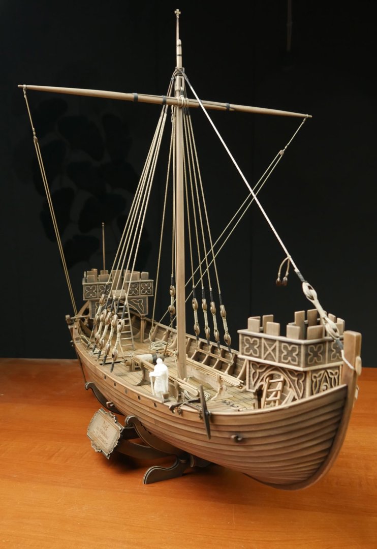
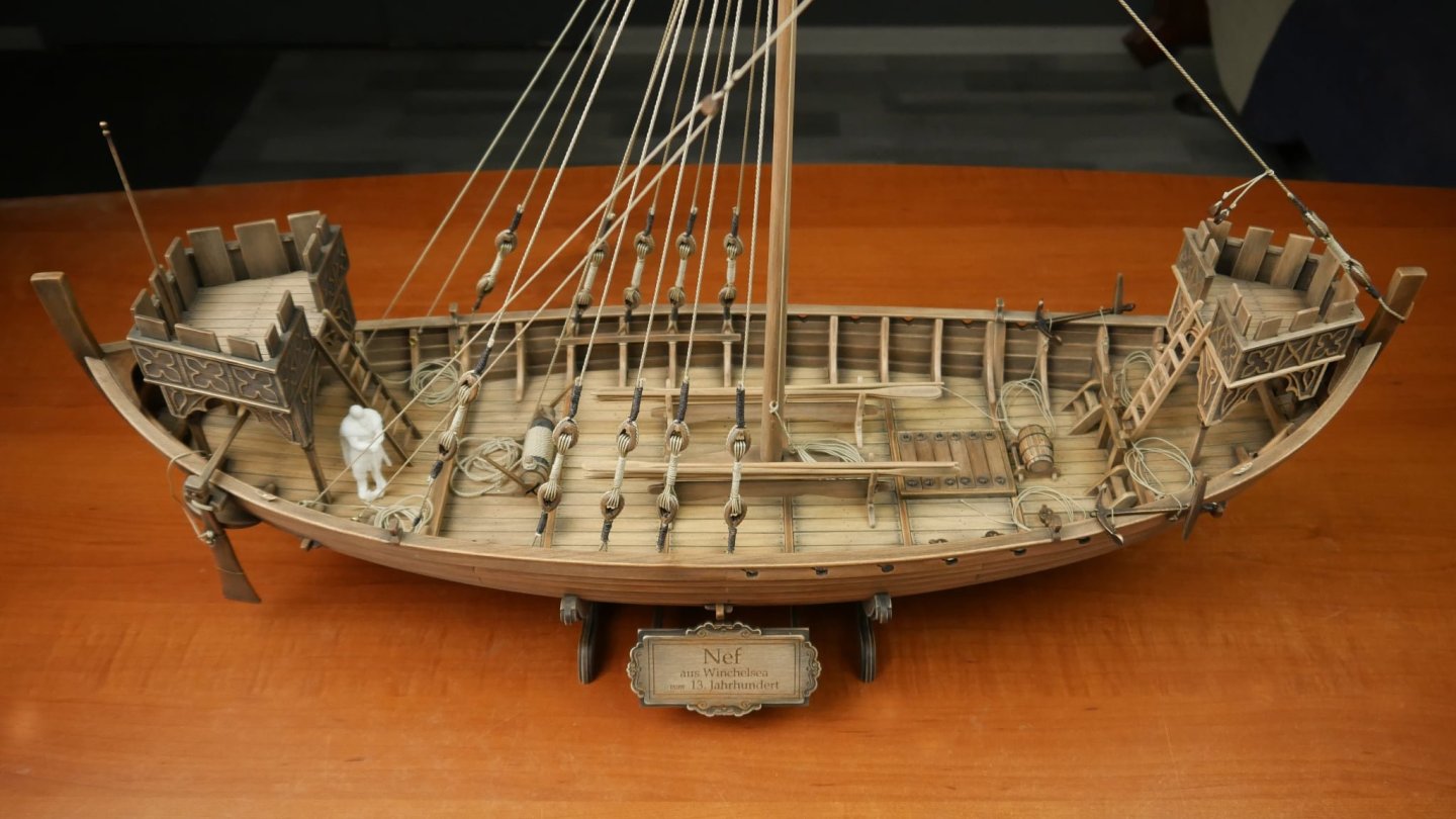
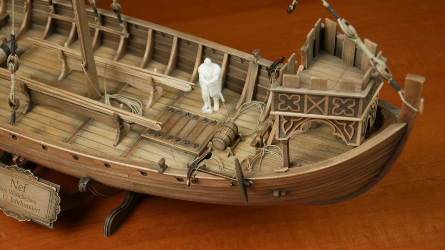
new kit alert! New kit on the horizon - Winchelsea Nef
James H replied to James H's topic in Wood ship model kits
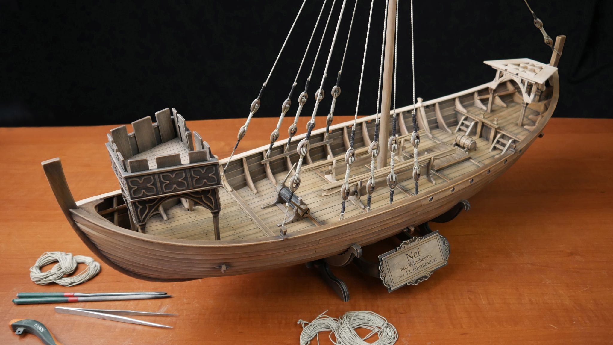
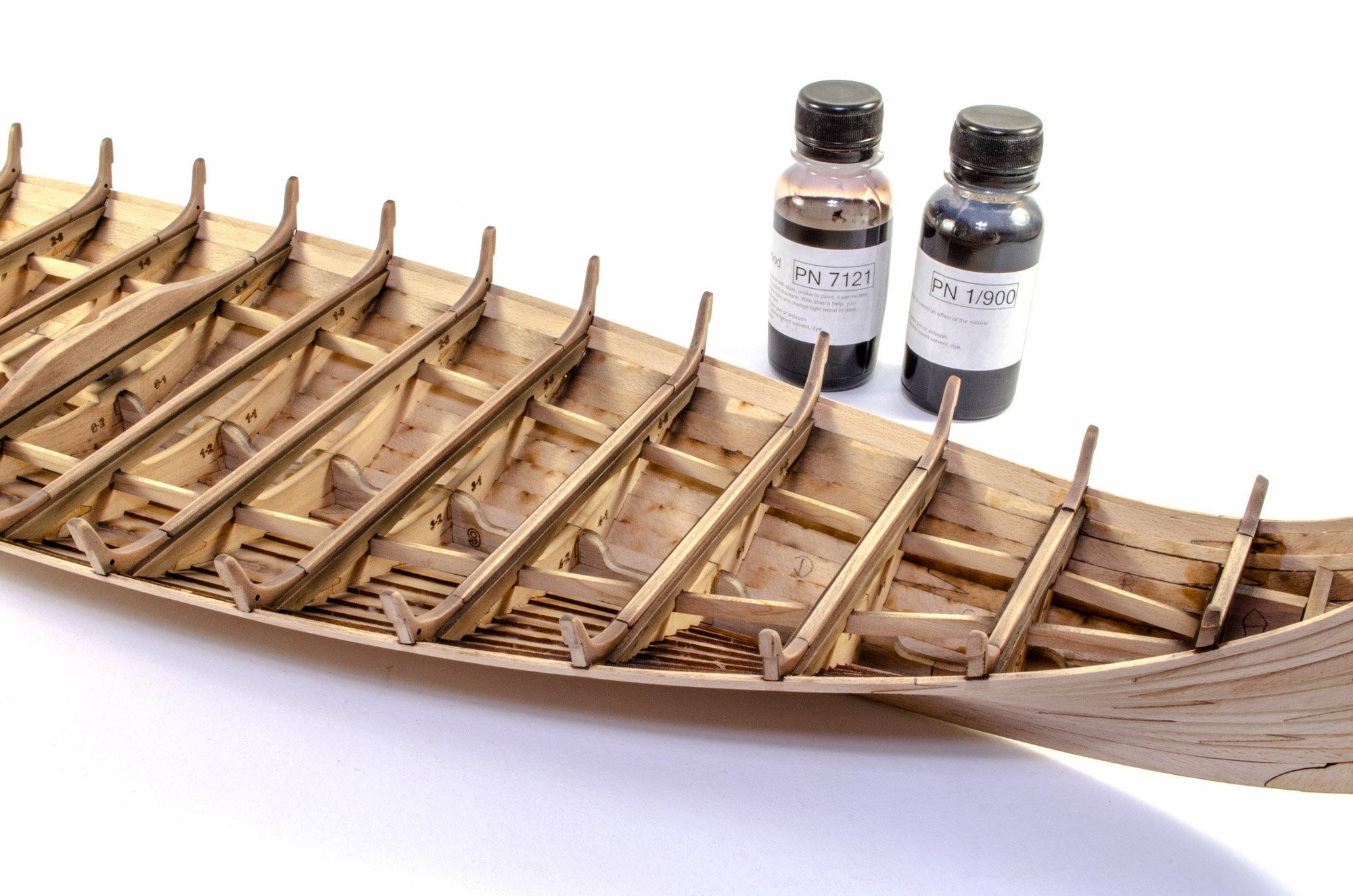
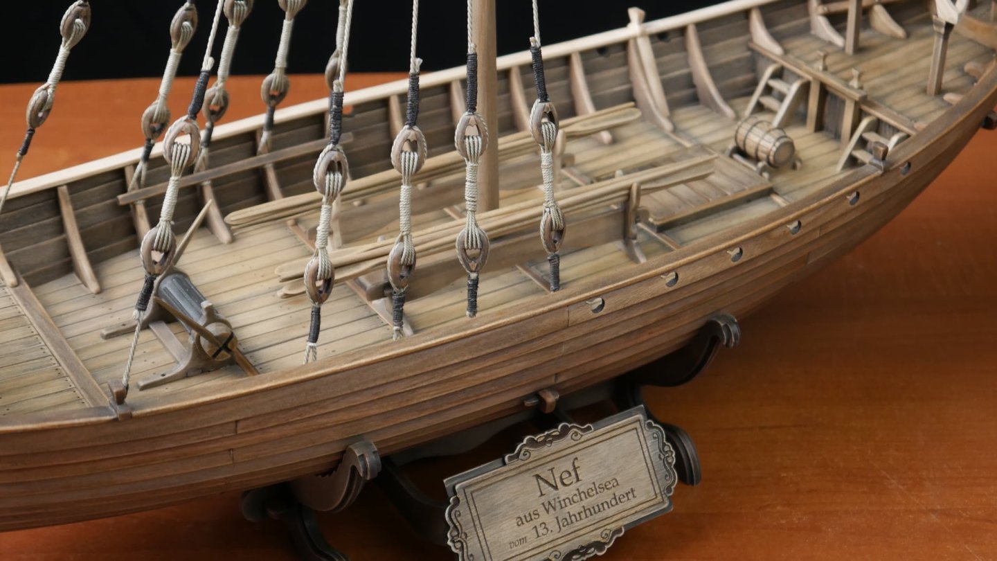
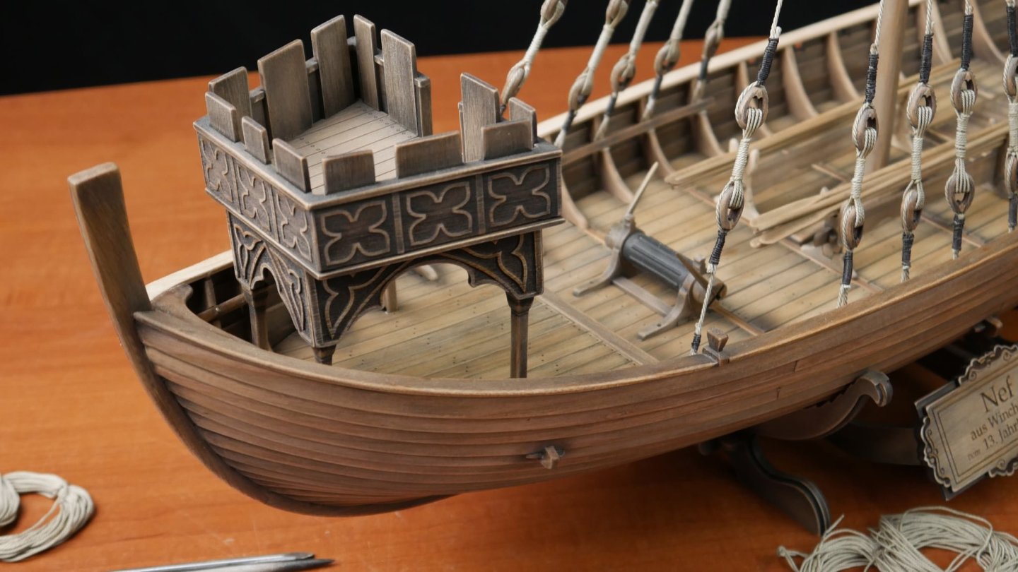
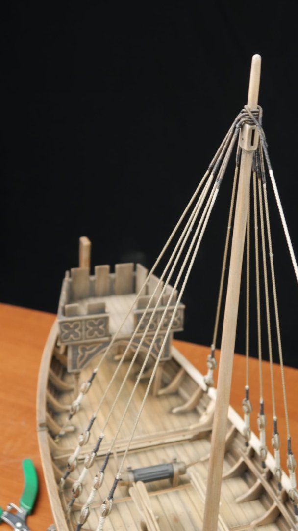
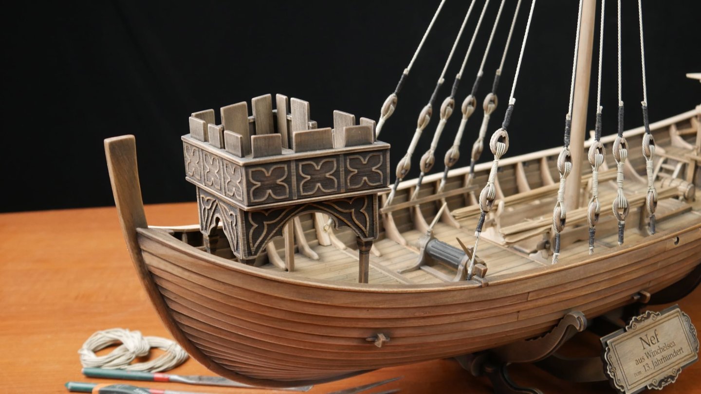
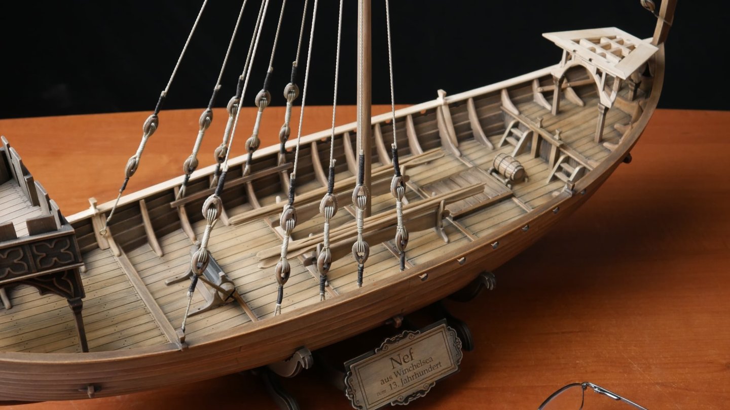
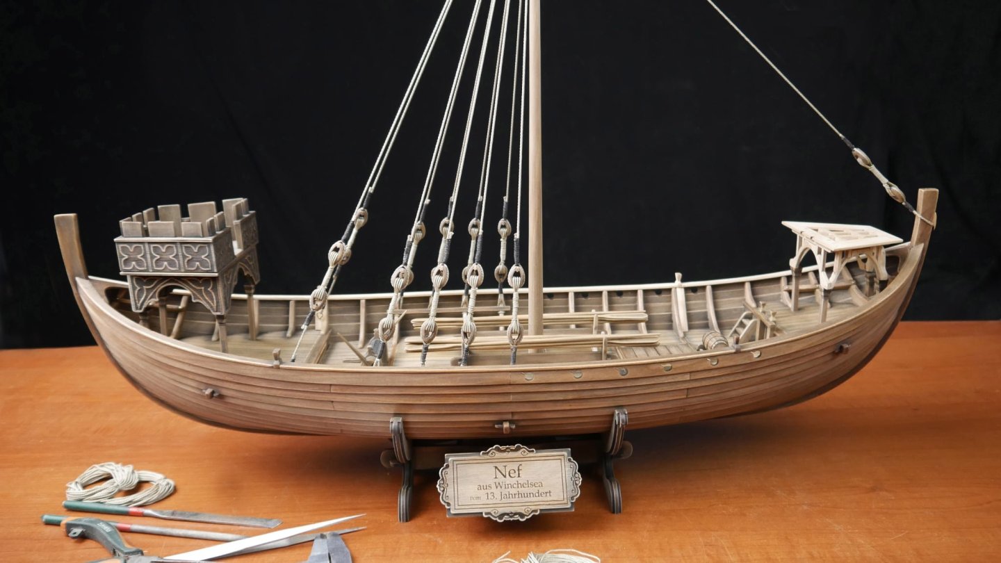
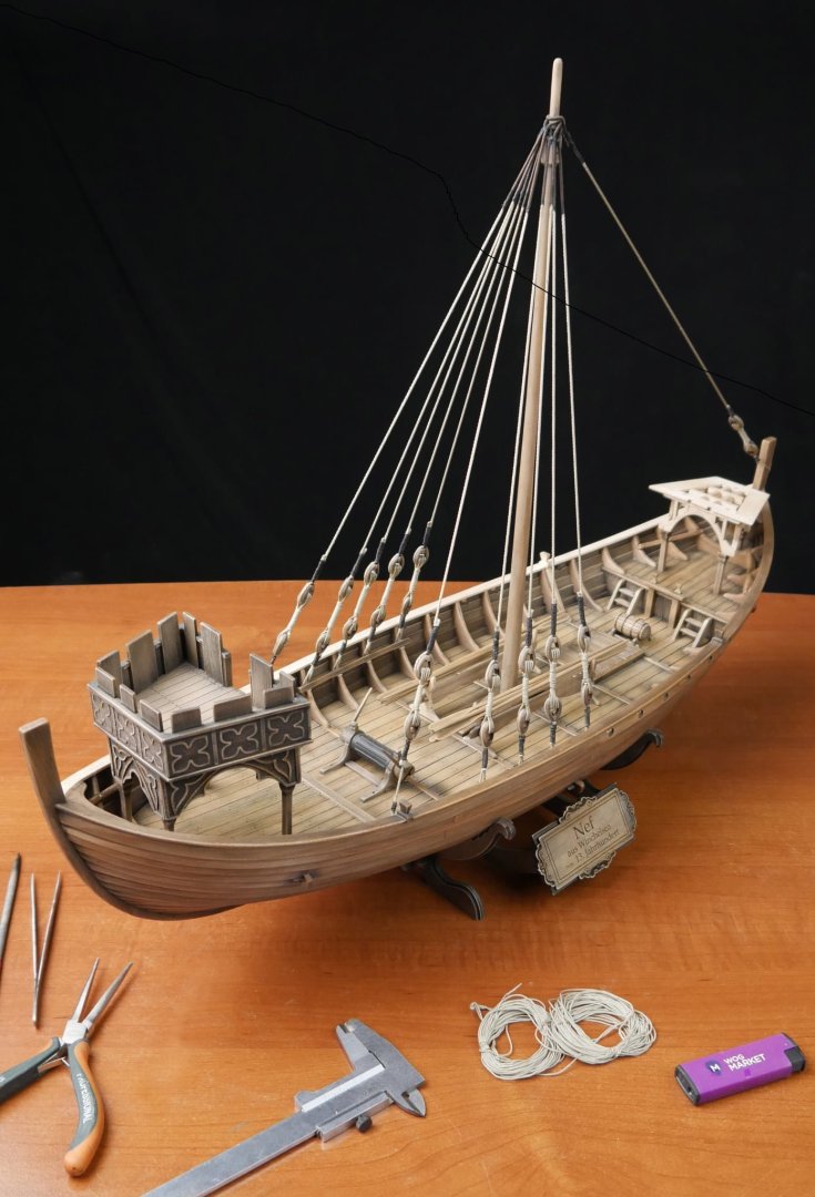
Here's a new set of photos of the prototype. Enjoy!


- 15 replies
-
- 13
-

-

-
- winchelsea
- medieval
- (and 1 more)
-
Welcome to our friendly little corner of the interwebz!
-
Shhhh, I told you not to tell anyone 😉
-
Lovely work, Glenn. Real nice to see how this is progressing.
- 241 replies
-
- 2
-

-
-
- Vanguarrd Models
- Harpy
- (and 1 more)
-
I used to use it for second planking when I first started building, and built many ships, both large and small, with it. The glue I used was Dunlop Thixofix. It absolutely stunk and you had to have a good method to apply so it didn't leave any excess or blobs.
-
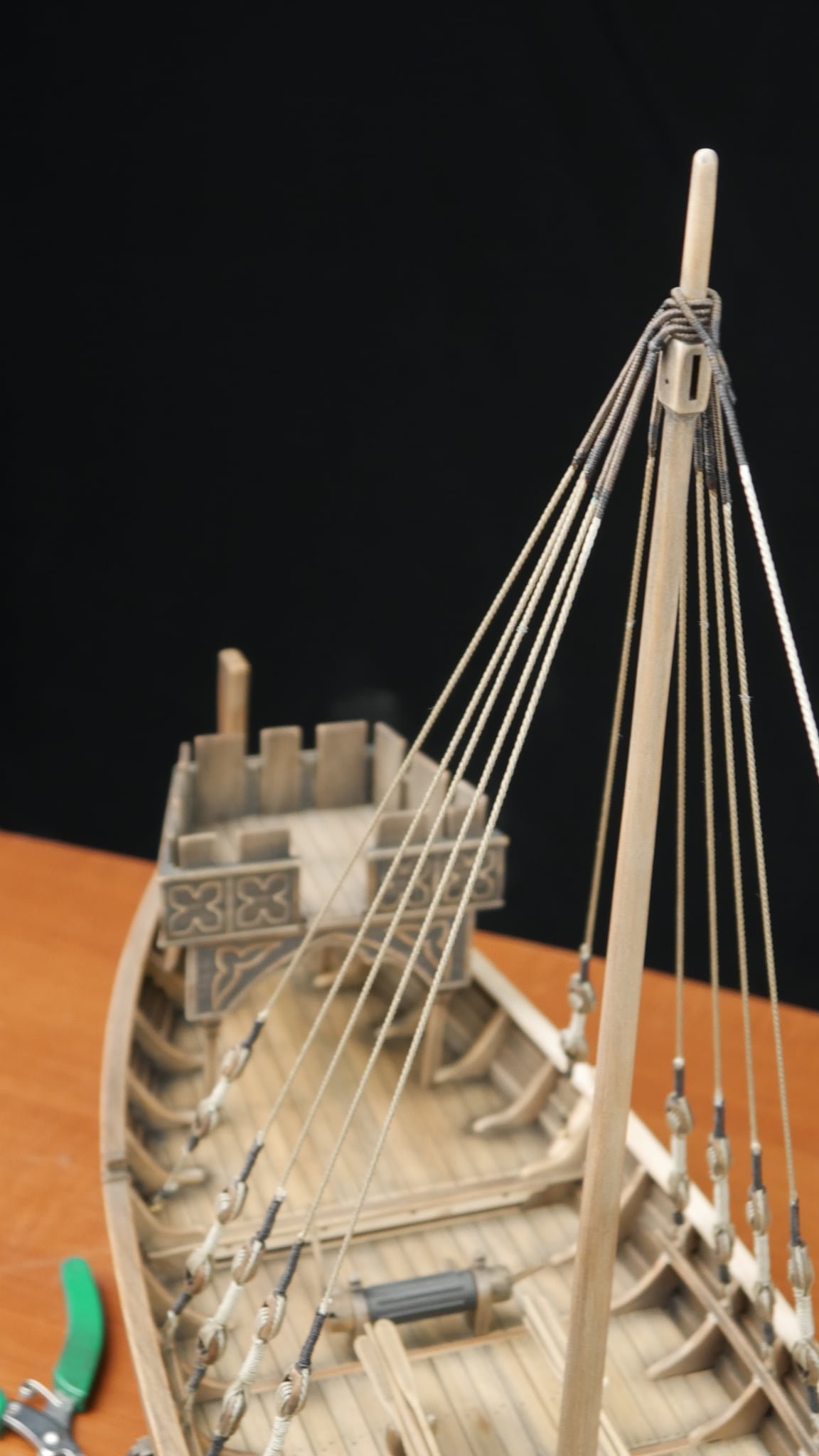
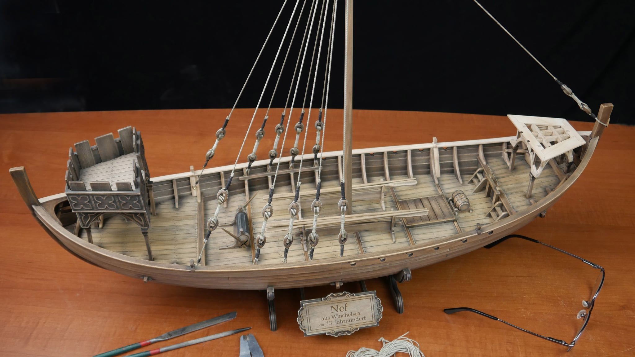
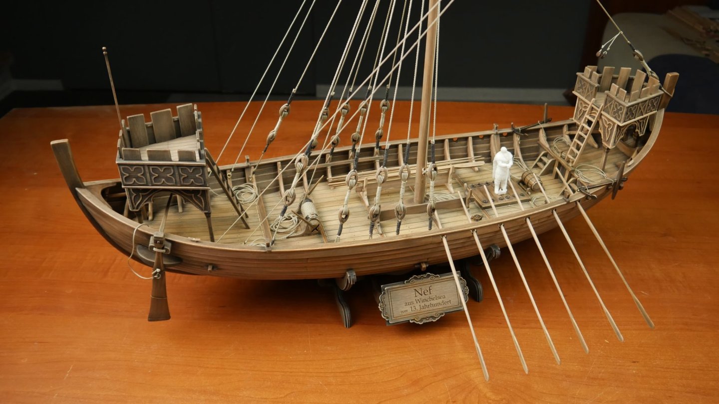
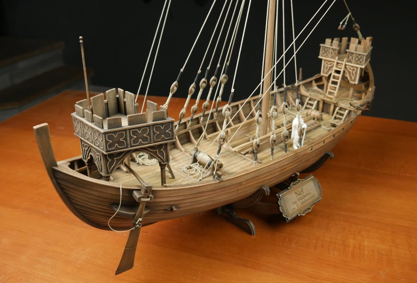
new kit alert! New kit on the horizon - Winchelsea Nef
James H replied to James H's topic in Wood ship model kits
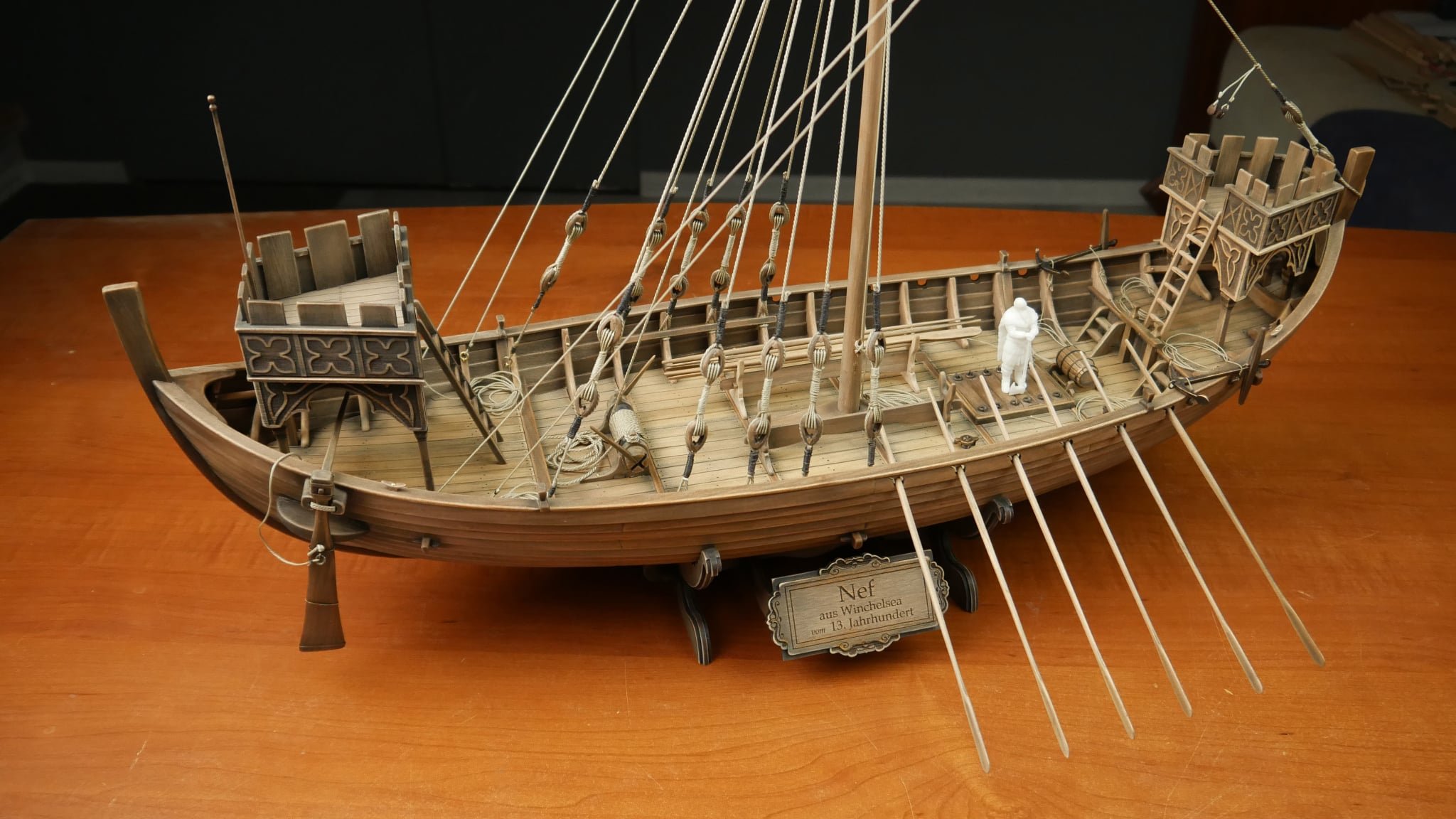
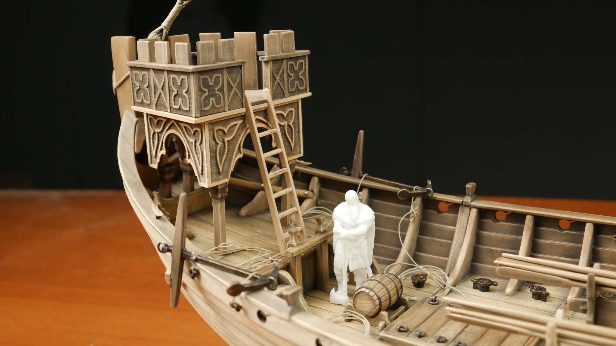
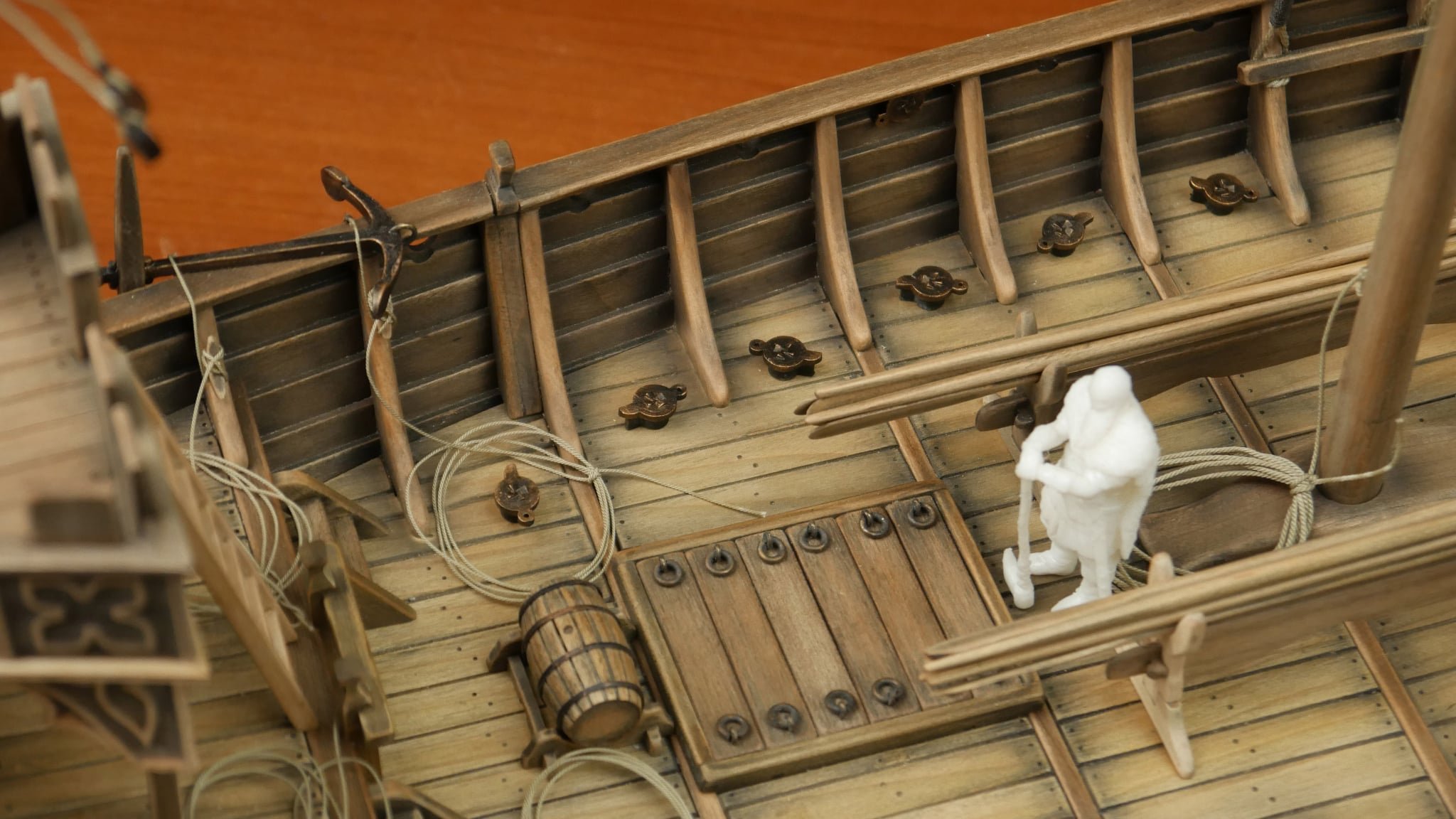
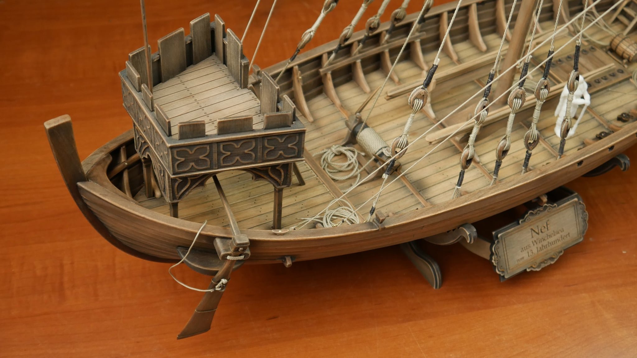
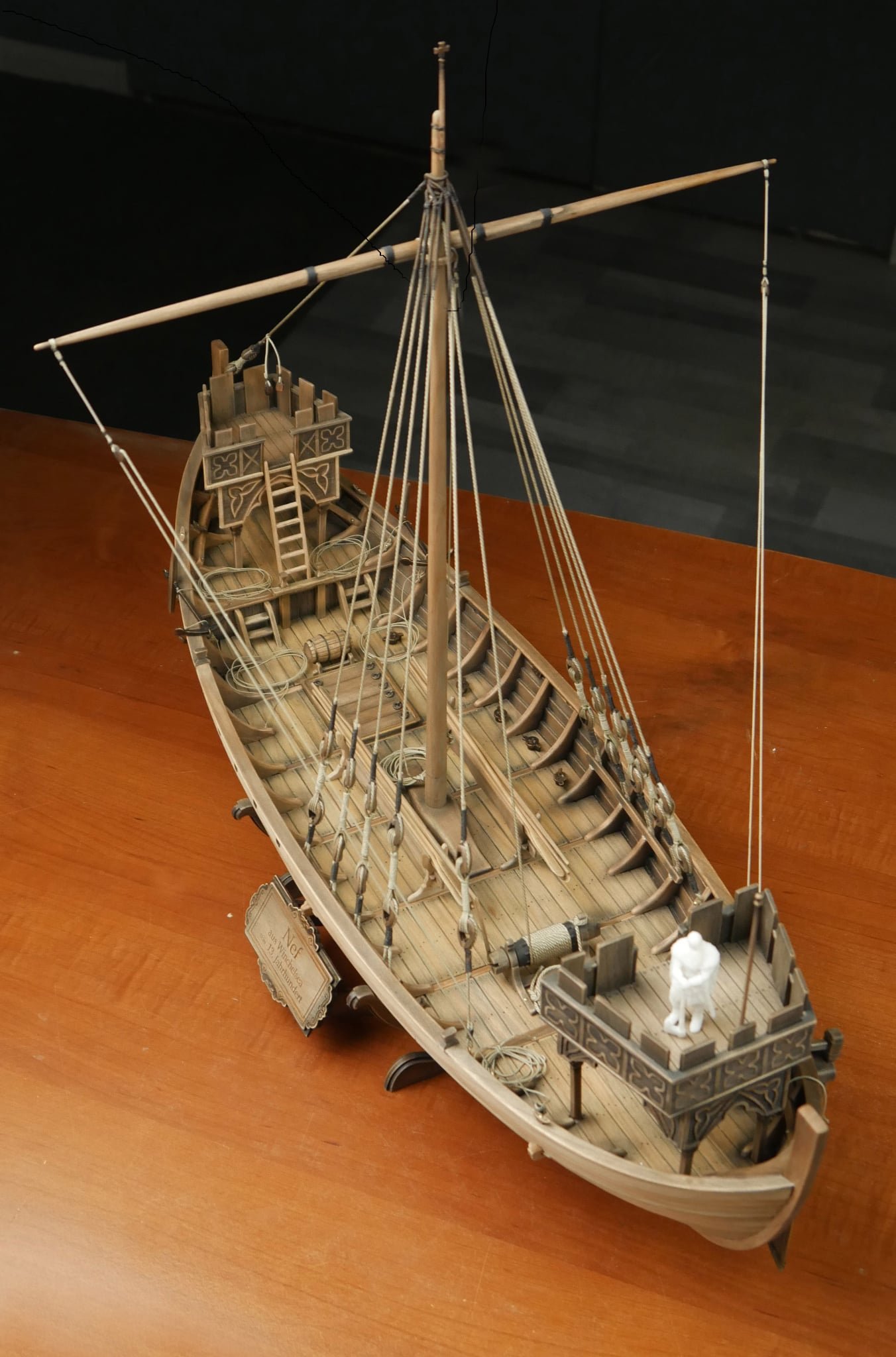
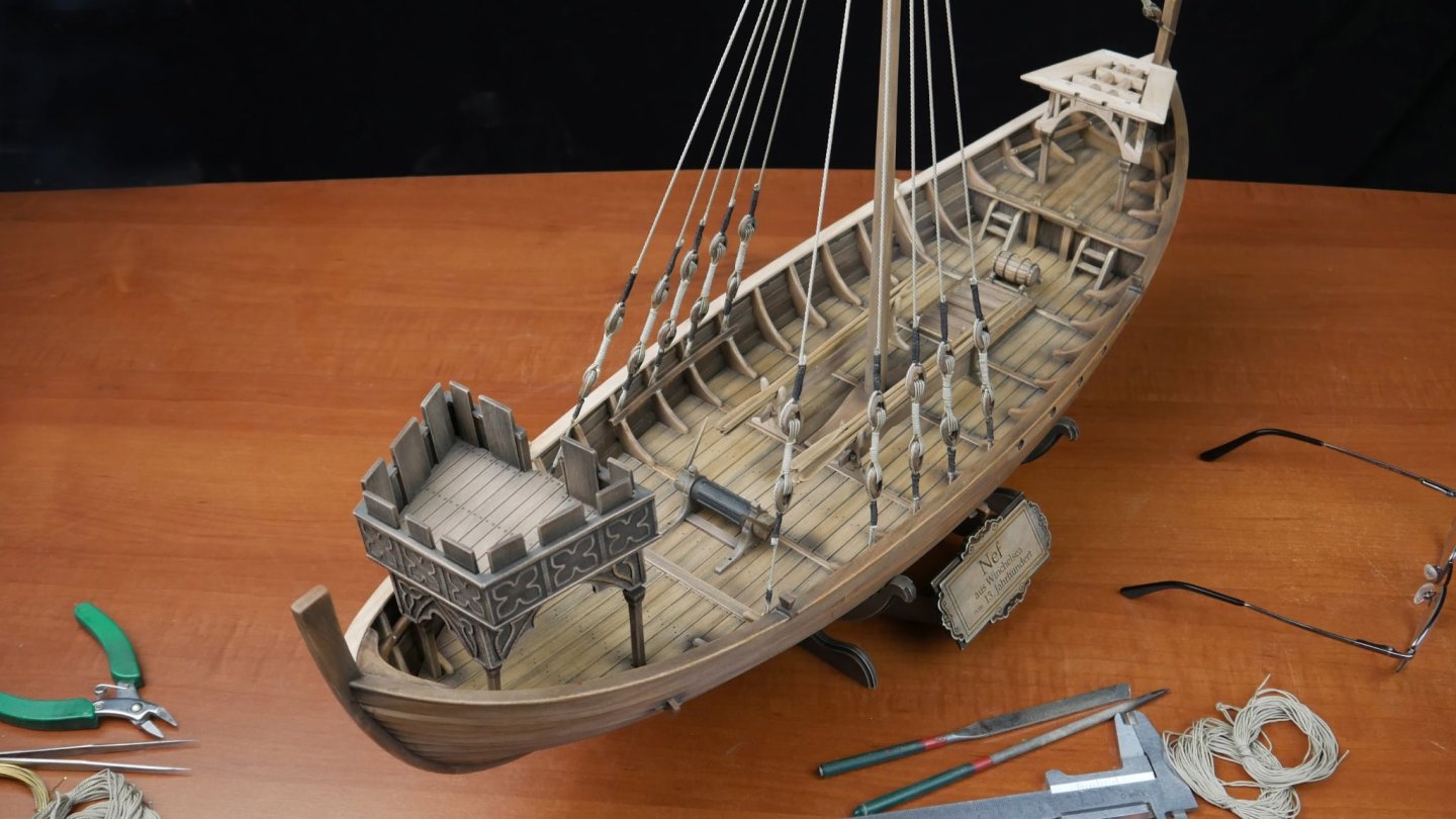
Here's the latest set of photos, giving you more of an overall idea of the finished model.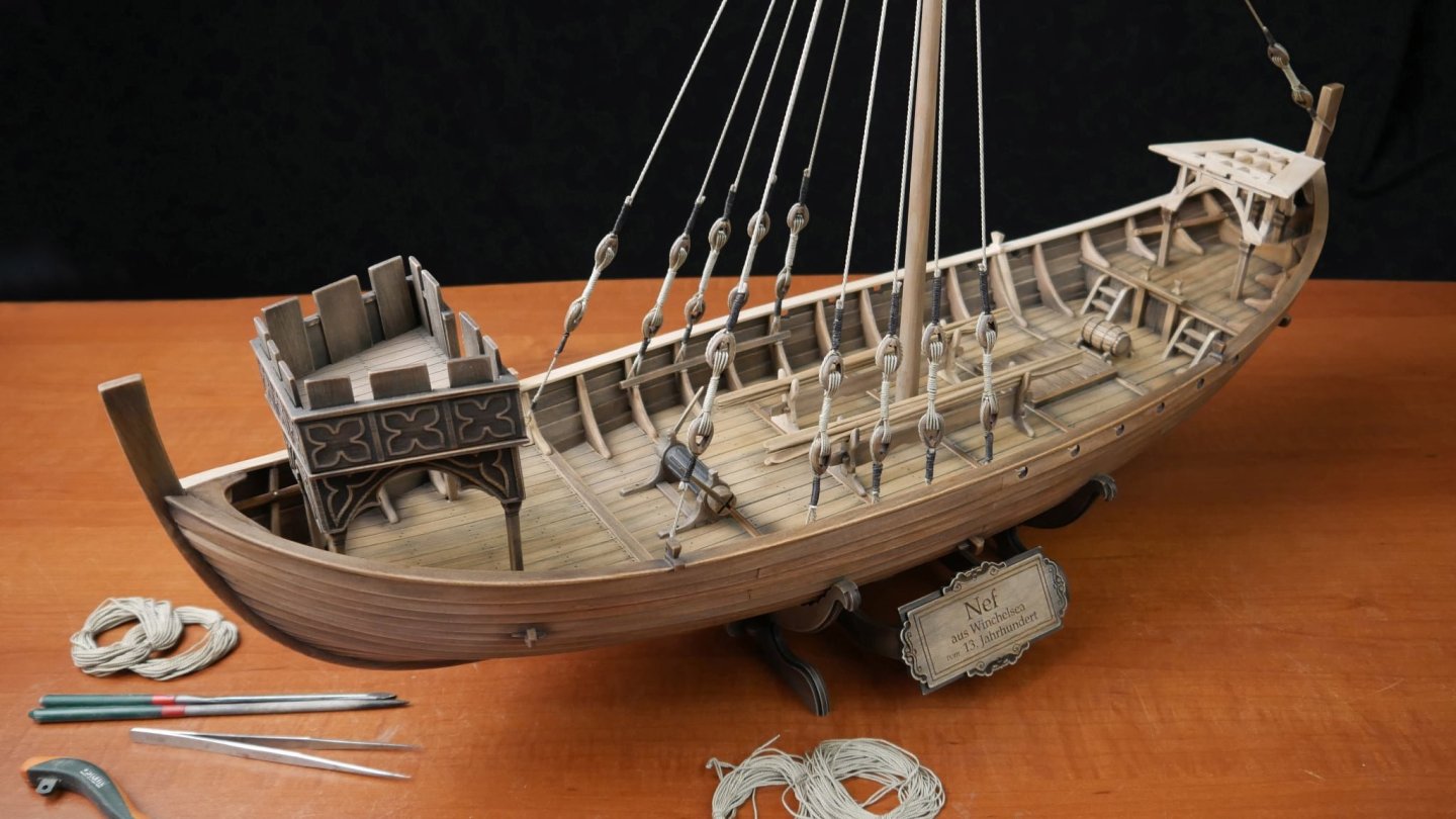

- 15 replies
-
- 11
-
-
-
- winchelsea
- medieval
- (and 1 more)
-
There's just too many of them to contemplate anything other than a black material. That'd need to be resin, and I'd need several thousand of them. I think it's a pass on this now. I'll just build and stain as out of box as I've HMS Surprise starting in the not too distant future.
-
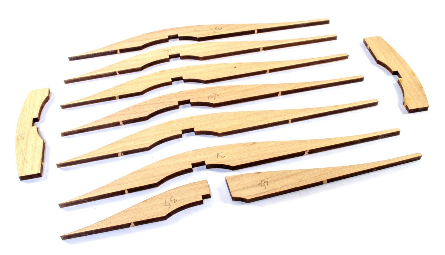
That's simply a technique that the designer used to ensure the stresses in the parts were catered to. If the planks had been single parts, they may well have split as you pulled them into alignment. It's the next best thing to having to steam those things into shape.
-
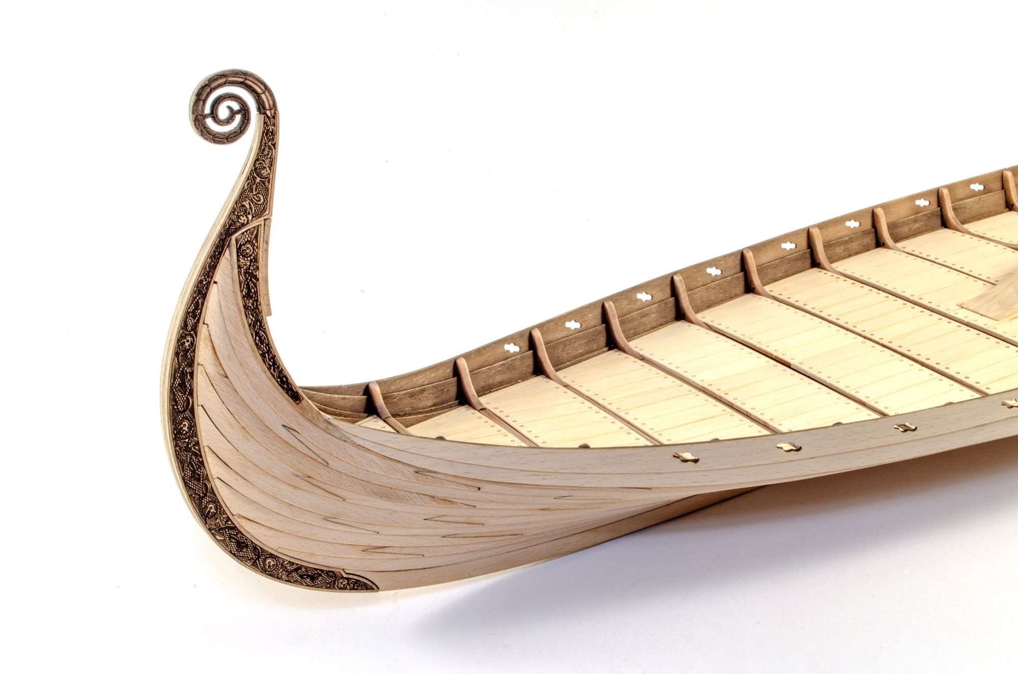
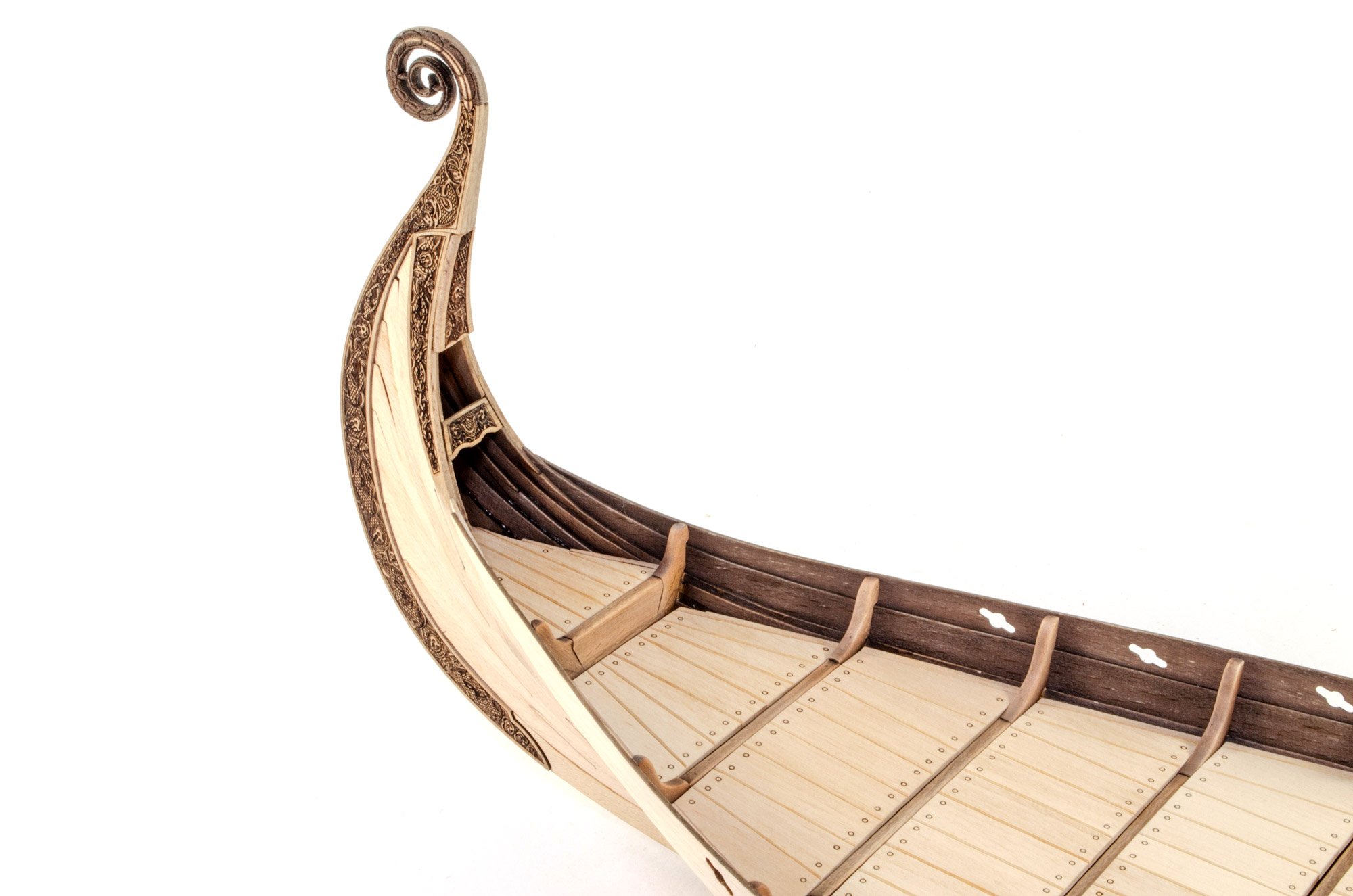
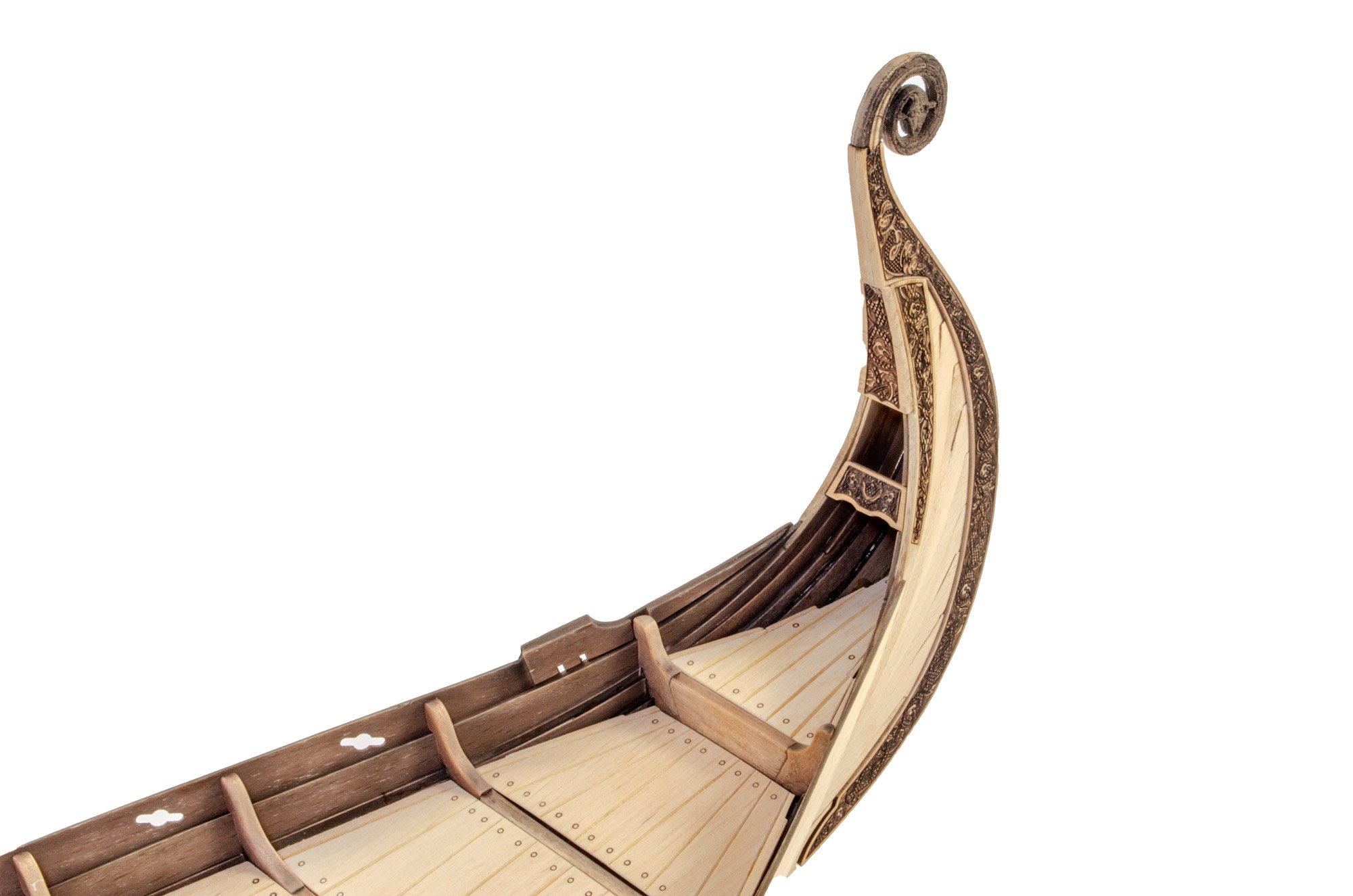
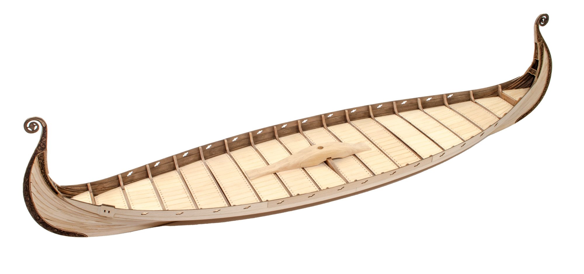
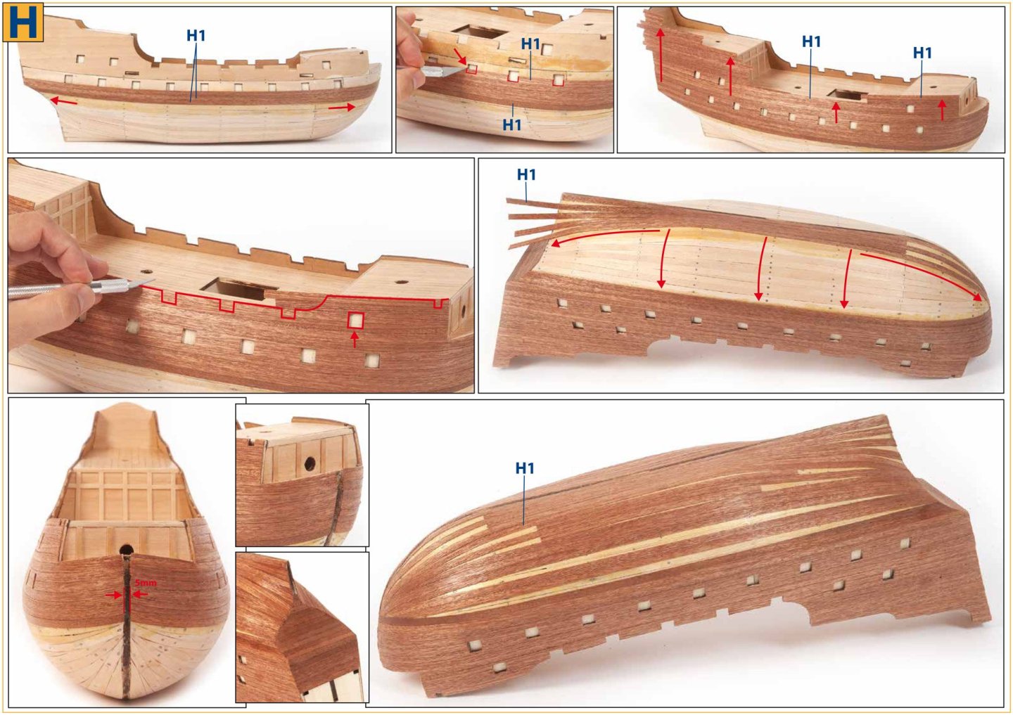
Work has been progressing painfully slowly, but I'm in no rush. Since my last update, the work has involved fitting the last three plank runs (10, 11, 12), adding patina and stain, and doing a lot of test fitting. The first job is the patina on the bulkhead deck beams/ears. 1/900 is first sprayed over these and then sanded back about 80%+. Next, stain 7121 is applied and then sanded. You can't really tell much contrast here, but it will be evident when the deck sections are down. One note, don't be stupid like me....do all this BEFORE adding plank run #10. I didn't, and needed to mask all spaces between ears, and then again when I masked the ears so I could paint those spaces. Two days of mind-numbing masking 😆 The temporary bow and prow curved parts are now removed and the laser carved sections fitted. This also included the other carved parts. All a bit of a jigsaw, but it fitted superbly. The inboard curved section on the inner bow and prow, needed to be soaked and bent slightly so match the concave area it had to be fitted to. Plank runs #11 and #12 are now treated with 1/900 patina, sanded, and then stained with #7013. The multipart plank runs are now carefully glued into position. You'll see here that I still need to shape the prow and stern into the scrolls that sit atop each. Here you will also see the rudder position that is a part of plank run #12, with a few extra parts fitted. Lastly, those deck sections are NOT glued down. They need patina and stain to be applied first. They are also slightly bowed as they're individual parts. They will sit nice and flat when glued though.


- 48 replies
-
- 14
-
-
-
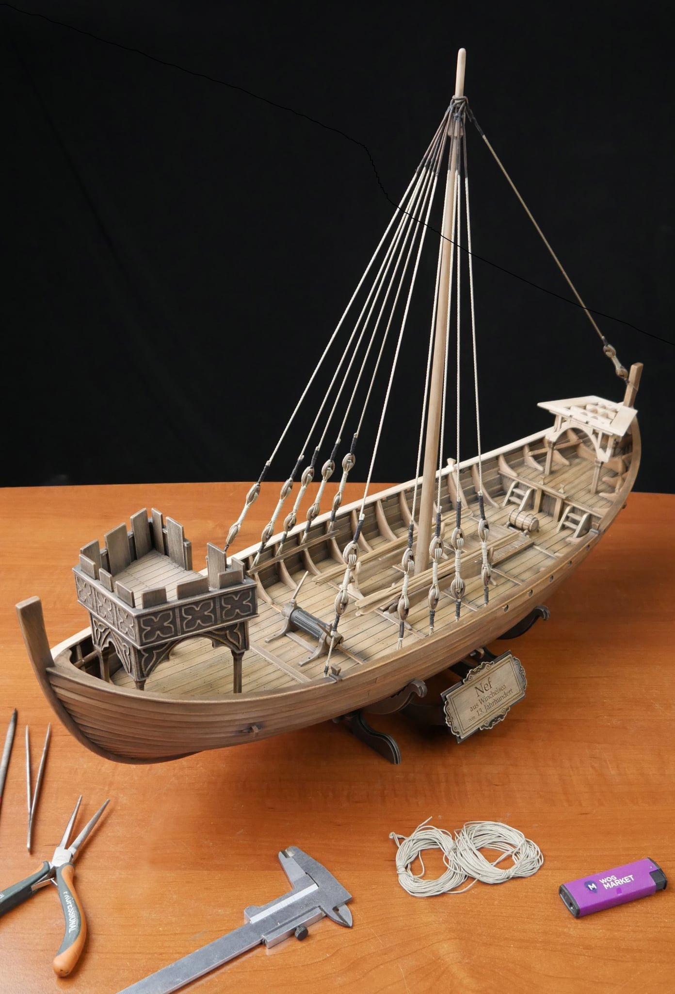
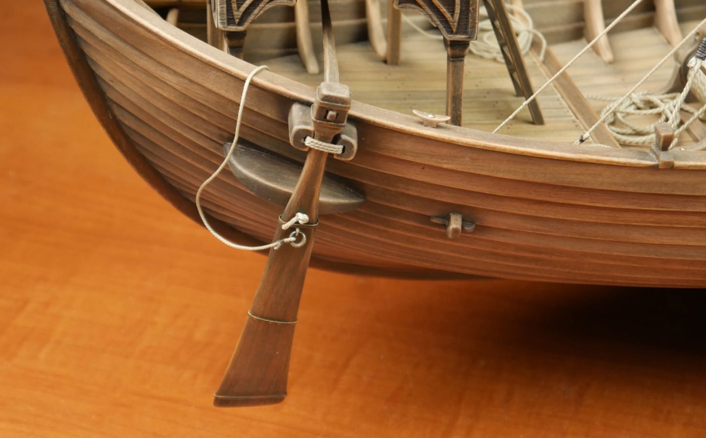
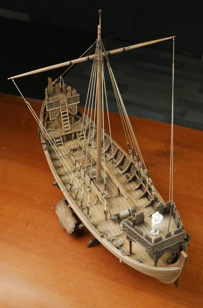
new kit alert! New kit on the horizon - Winchelsea Nef
James H replied to James H's topic in Wood ship model kits
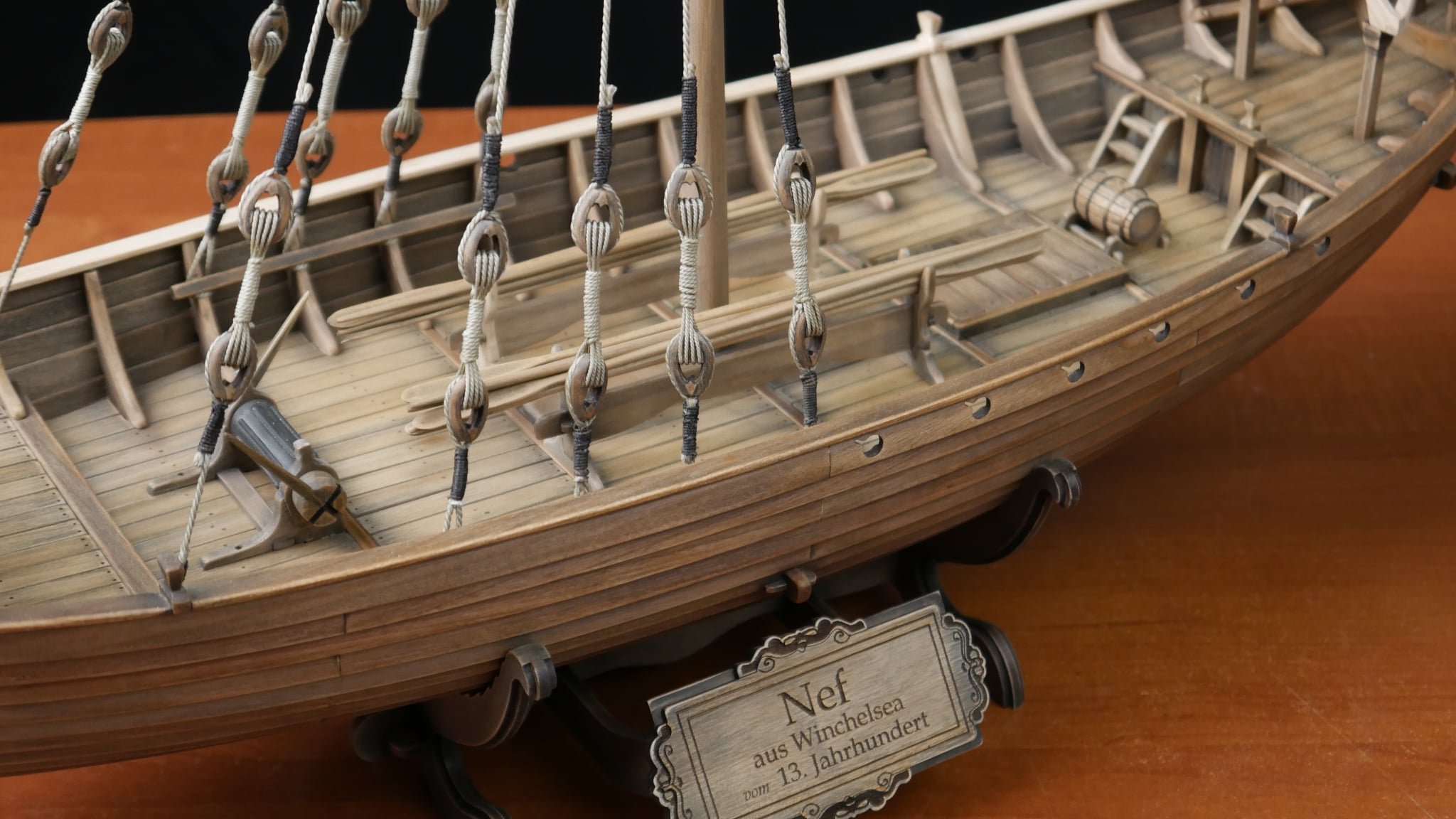
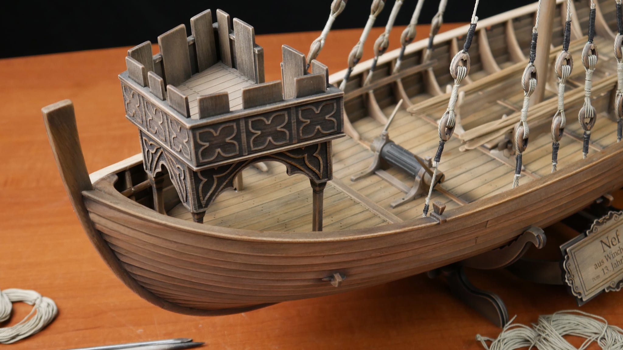
Pavel has kindly sent me some extra photos of this kit development. I'm told this will be released close to the end of May, give or take.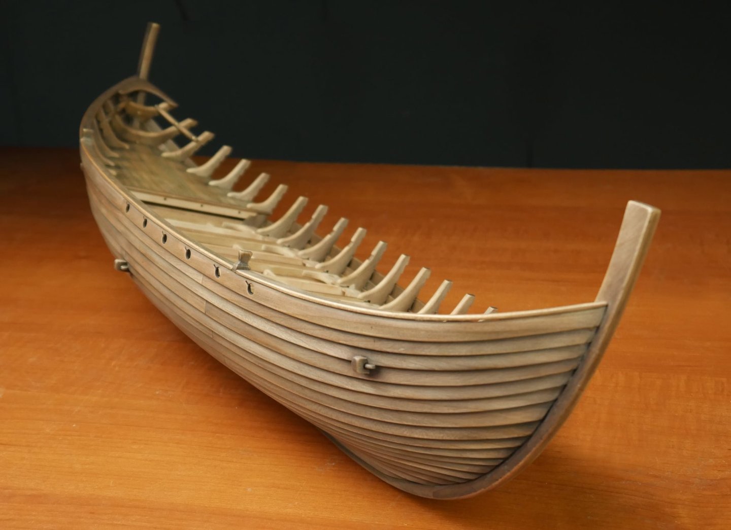

- 15 replies
-
- 14
-
-
-
- winchelsea
- medieval
- (and 1 more)
-
Nice to see you're importing OcCre to North America. Welcome to MSW!
-
I'll be following this one!
-
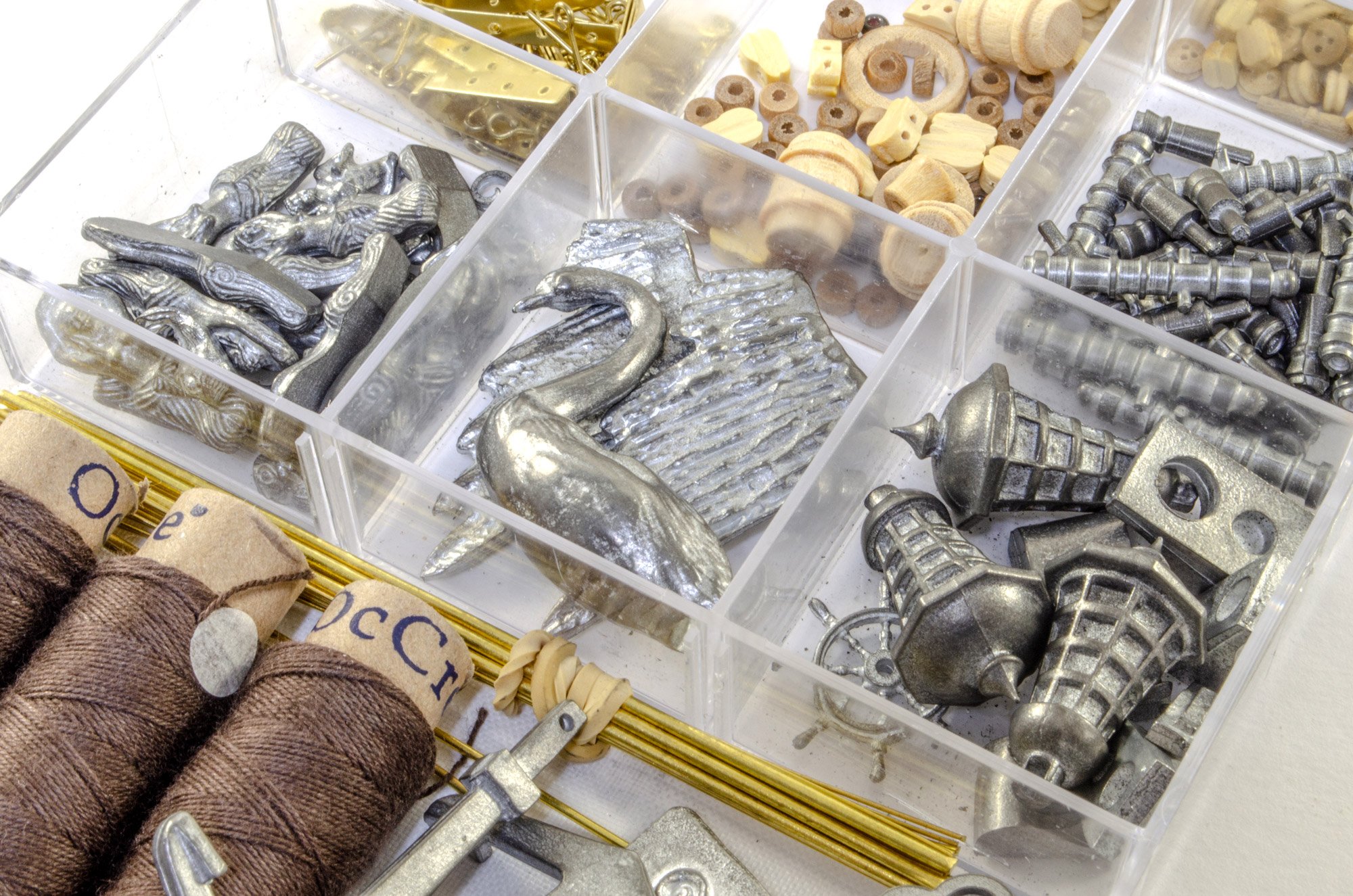
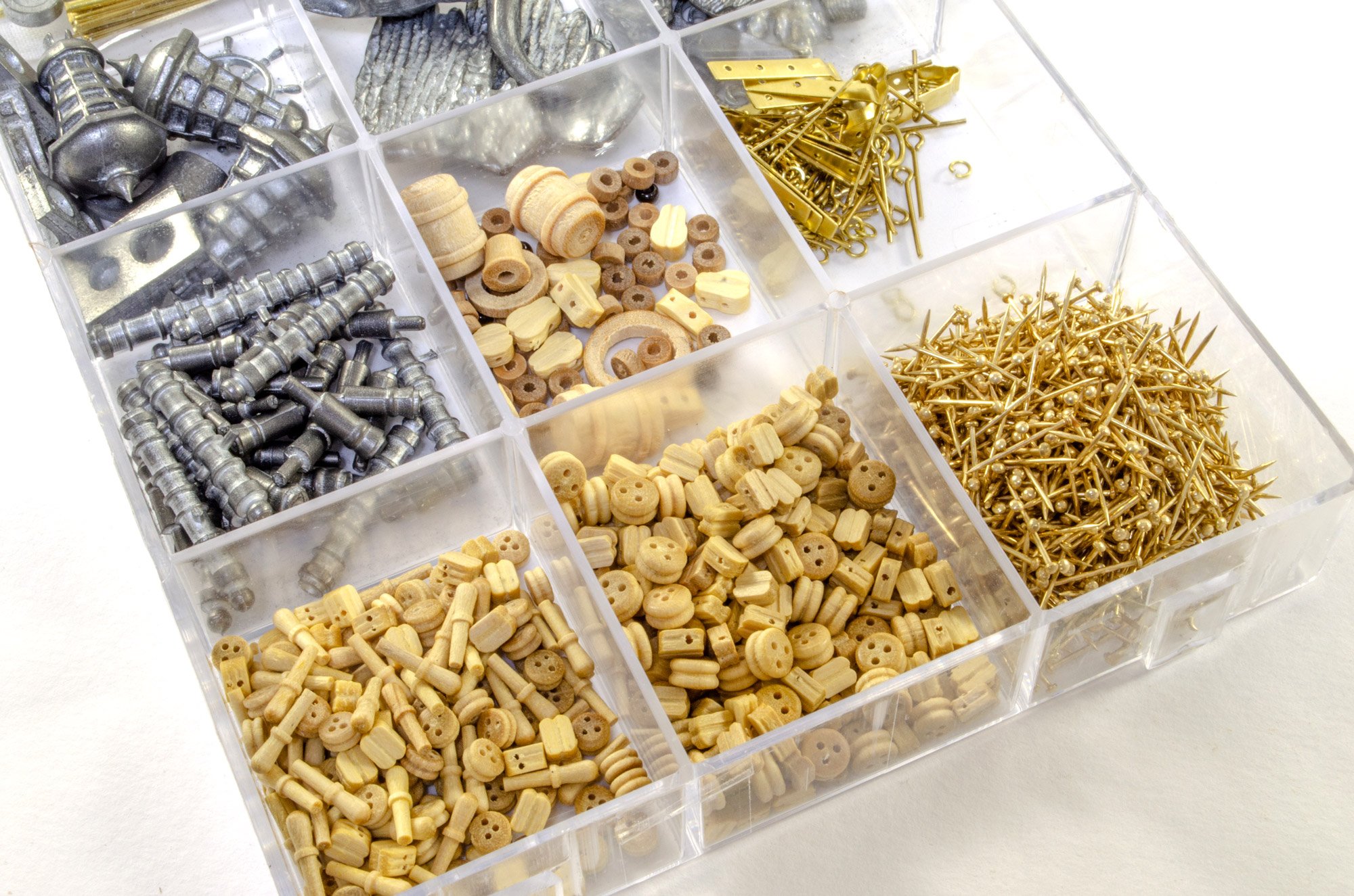
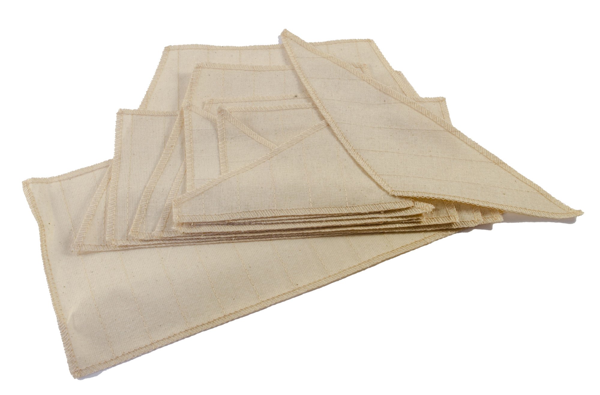
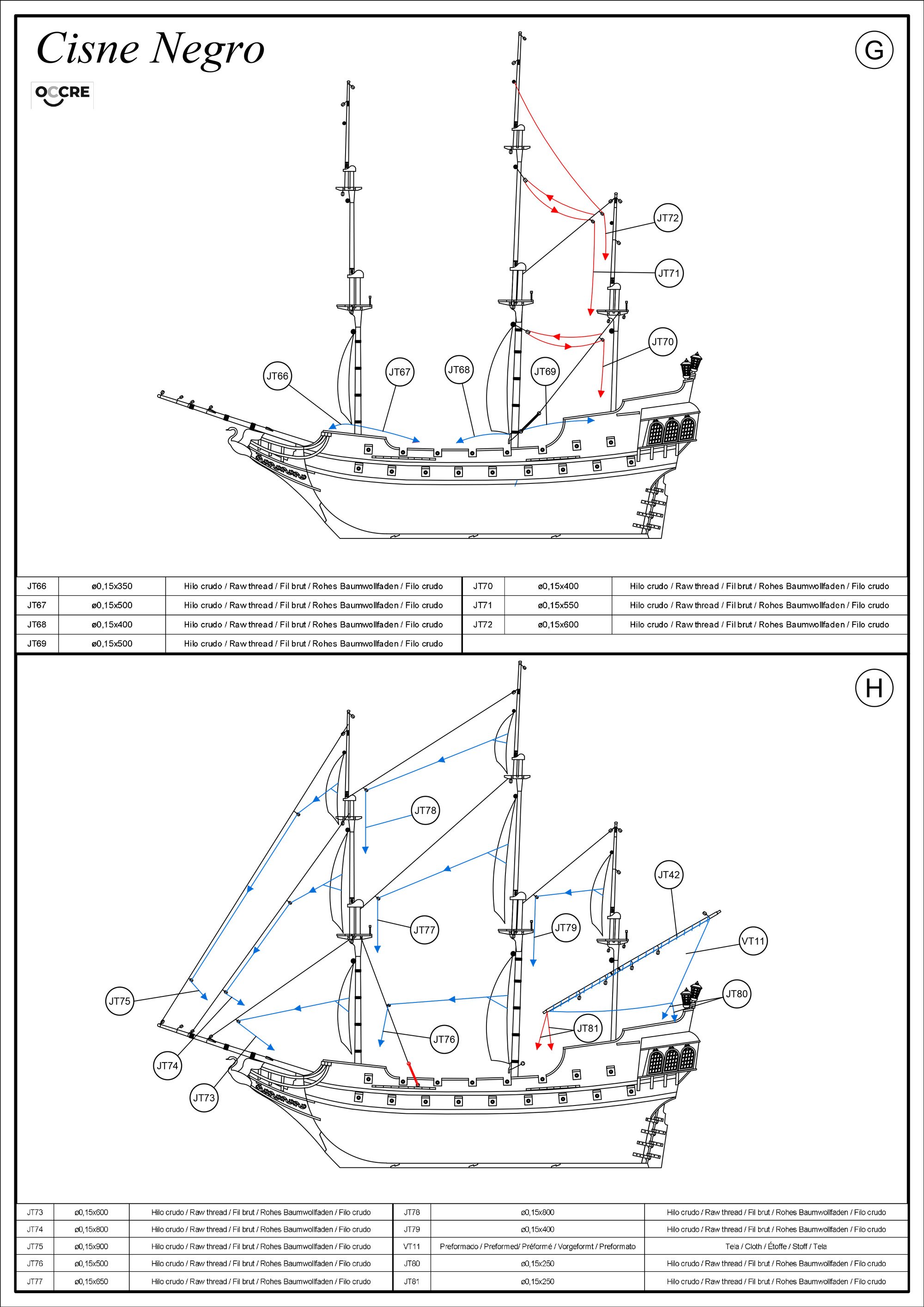
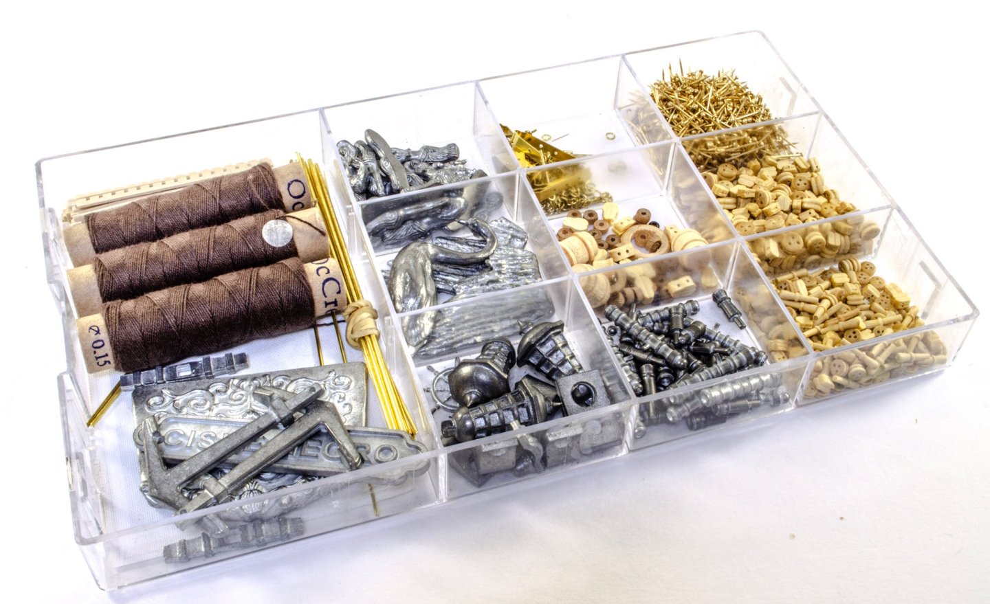
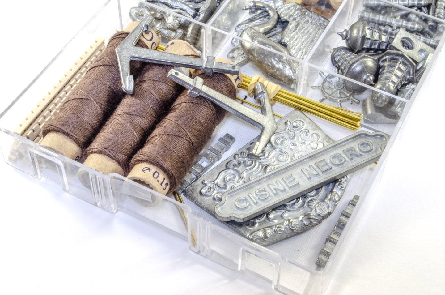
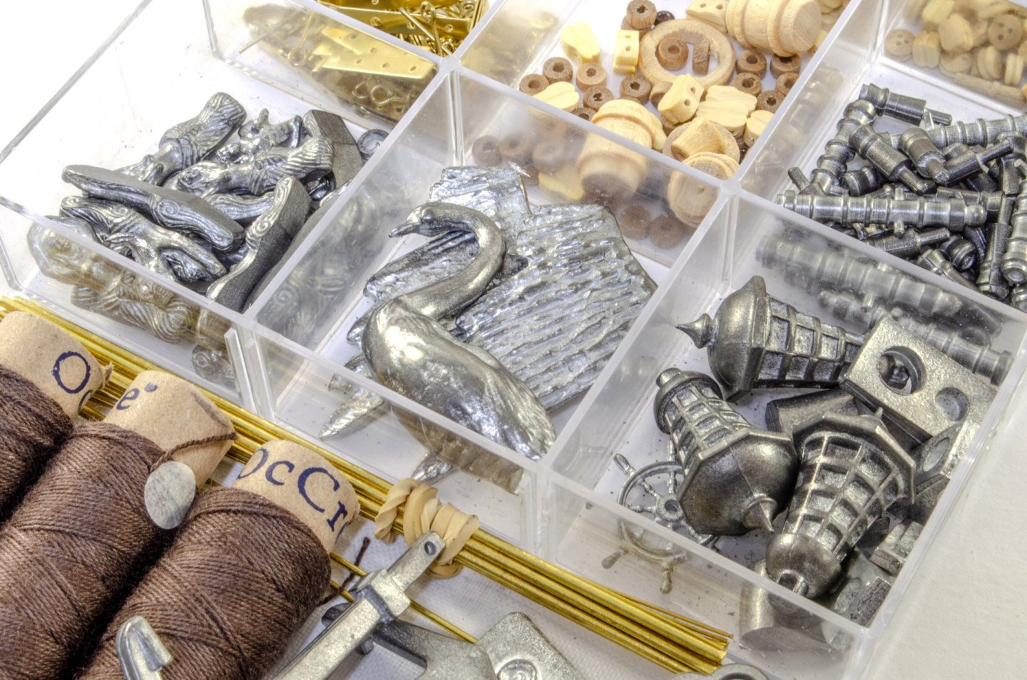
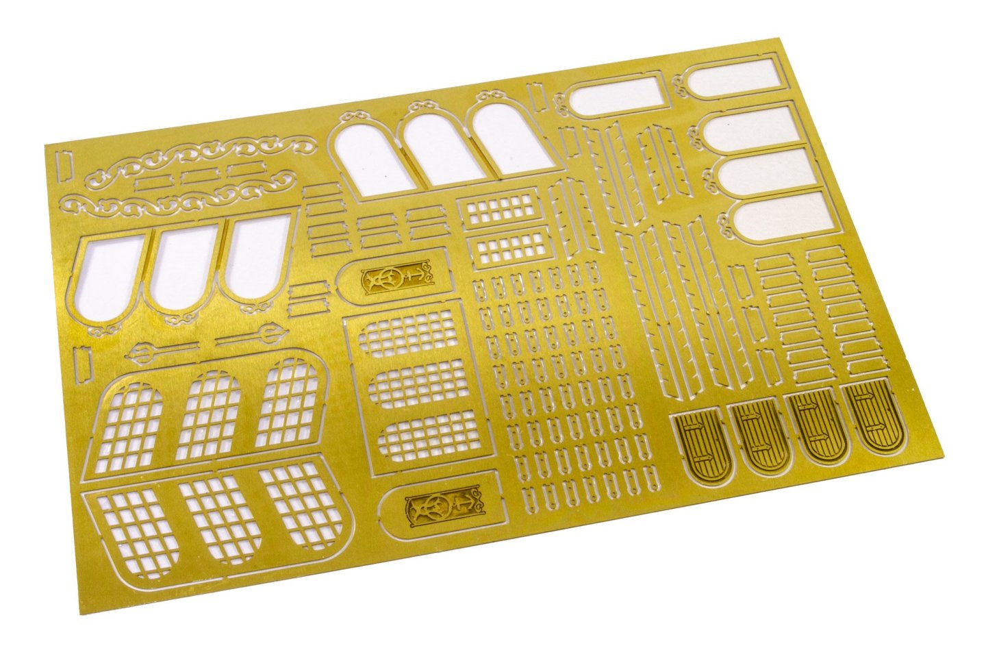
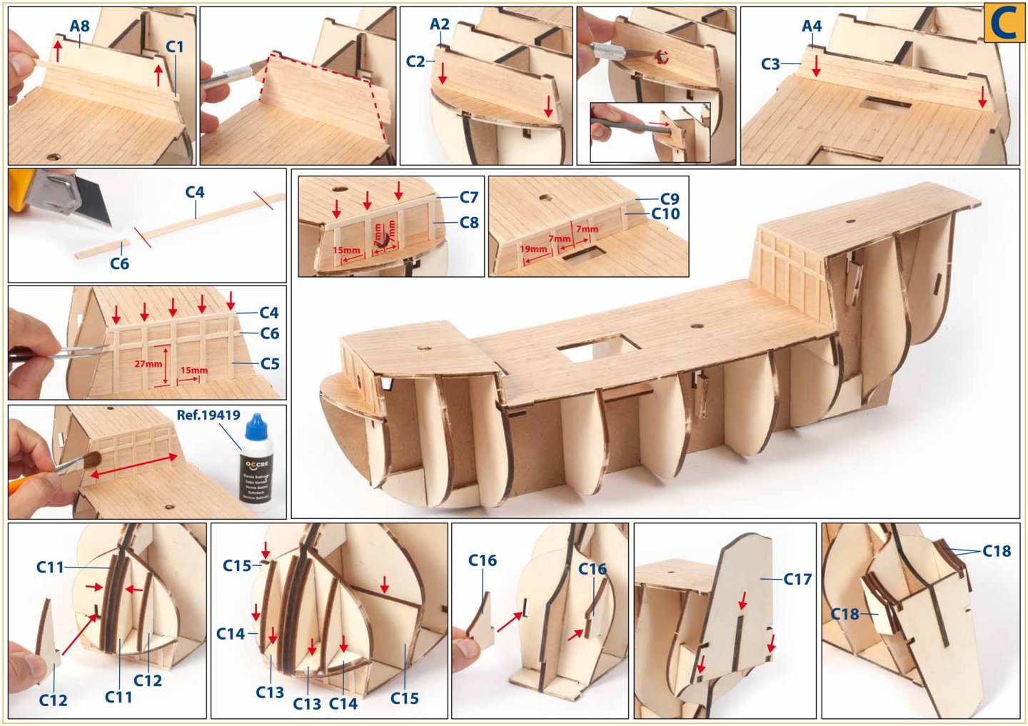
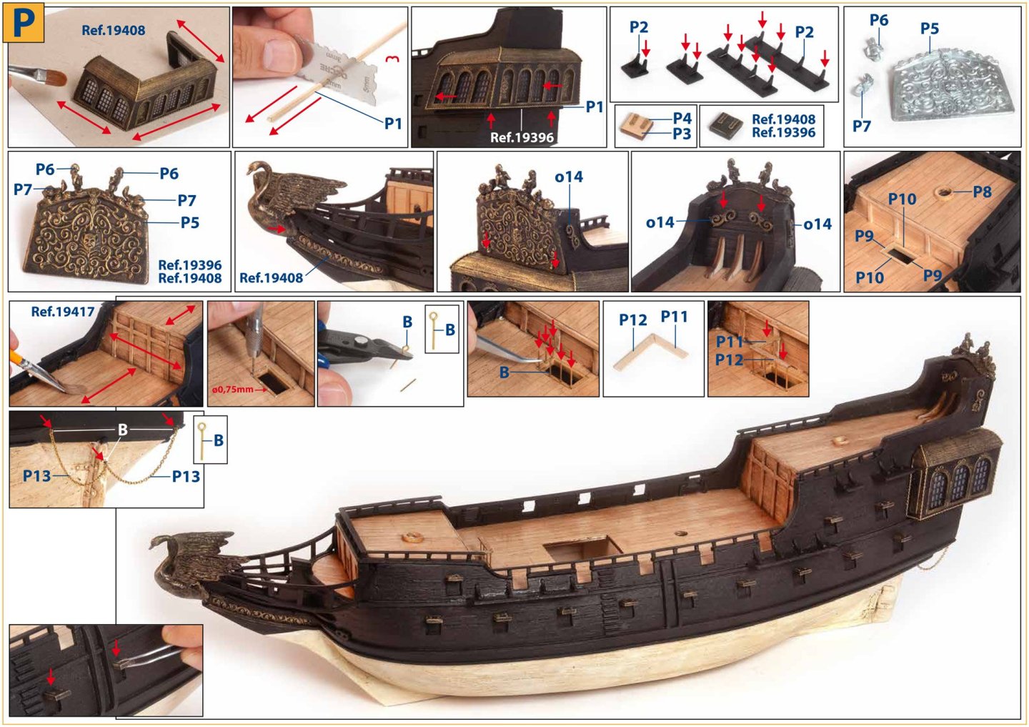
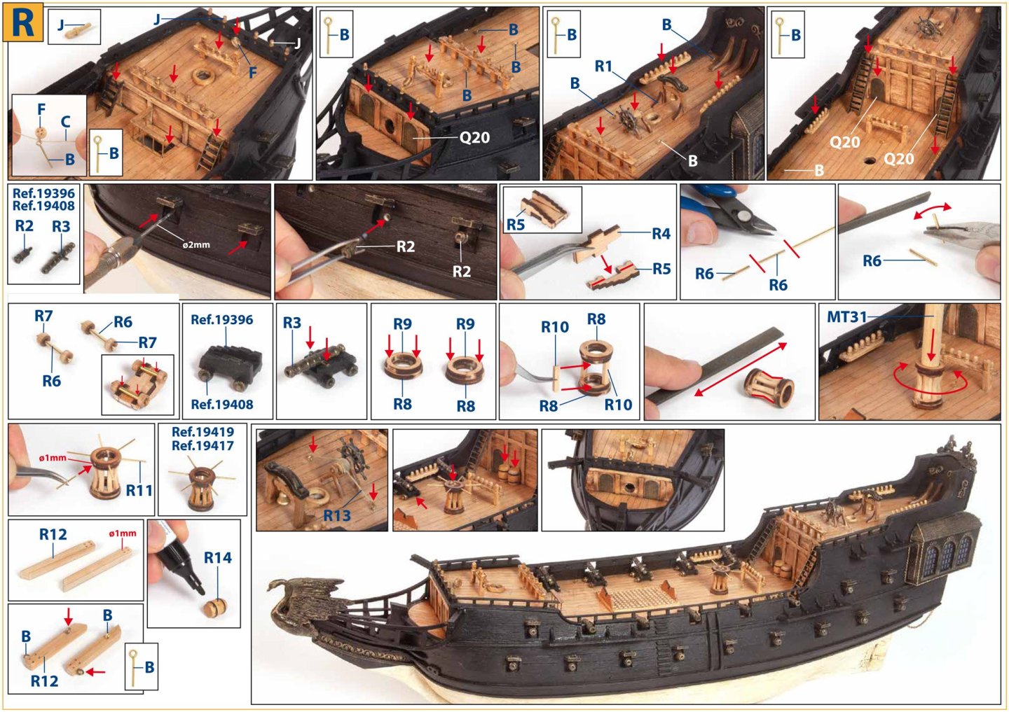
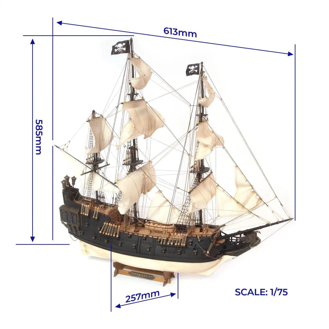
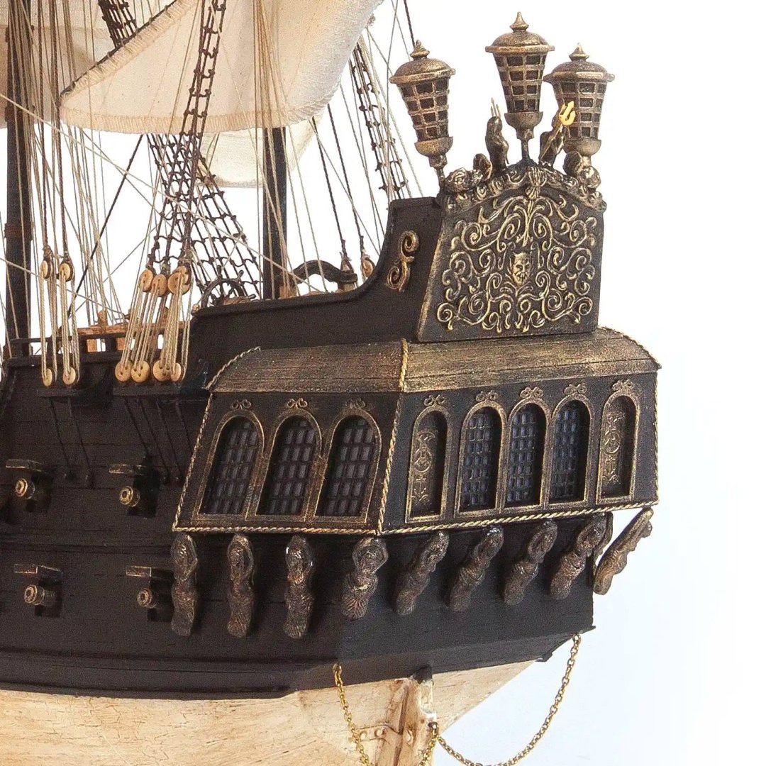
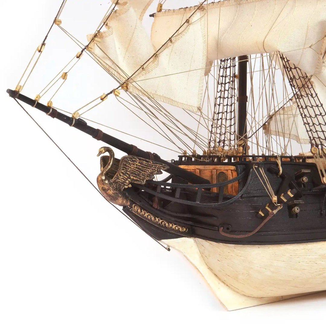
A single fittings box is included. This kit has many cast metal features, such as the black swan, obviously! The latter is cast in three parts (body and two wings). Also note the name plate, anchors and stocks, lanterns, ship's wheel, and unusually, the mast cap squares. Gratings are supplied as combs, as is traditional, and brass wire is included, for things such as mounting the lanterns. Three spools of rig cord in arm brown are included, but this is only to pack out the remainder of the compartment, as the rest of the cord is supplied in an envelope. Also here are the rigging blocks and deadeyes, belaying pins, and other wooden details such as barrels. A good number of brass pins are included too, as are pre-formed brass rudder hinges. I did mention an envelope. This contains a whole suite of pre-sewn sails and the remainder of the rigging cord, in both natural and dark brown colours. Cord size is clearly printed on each spool. There is actually another envelope that lurks at the bottom of the box so that it's kept flat and less likely to bend. This contains a large, single sheet of photo-etch parts. Numerous are the gallery parts, window frames and bulkhead doors from the quarter deck. You'll also see scroll decor, and most unusual are the ladders which are typically made from timber. PE quality is every bit as good as that found in other contemporary kits, and the connecting gates are small enough that only a little pressure will be needed to remove them from the sheet. Instructions All instructions are supplied in the kit, but they can also be found online, should you want to study them on your computer before the next bench session. These amount to 63 colour-printed pages which detail everything in photographic form apart from the masting and rigging drawings. These are supplied as line drawings. There are NO extra plans included here as they simply aren't needed. Everything is in the manual. Here you'll also find the sheet maps so all parts can easily be identified. Conclusion This kit is very similar to the Artesania San Francisco that I built as my first ever wooden model, so I don't doubt that a relative beginner should be able to tackle this build, but I would suggest some experience beforehand, or at least in another modelling genre...simply so the modeller has a little focus and understanding of how to approach a build that contains different media. The model is also presented at a good price point too, and will doubtless appeal to those who have a love for pirate ships, but want to build a legitimate wooden kit of such a subject! The Black Swan also isn't 'too' large, relatively speaking. She's 613mm long, including bowsprit, and 585mm tall. If you want to sit her on a shelf, note that she's 257mm wide, so not too imposing. My sincere thanks to OcCre for sending out this kit for me to review on Model Ship World. To buy this kit direct, click the link at the top of the article. ALSO... If you need a paint set to go with this kit, OcCre have their own acrylic set. This can be bought HERE for £25.99. In here you will find two 50ml bottles containing walnut dye and satin varnish. The remainder are 25ml bottles. The supplied colours are gold, black, white, bitumen, and lastly a bottle of primer.


-
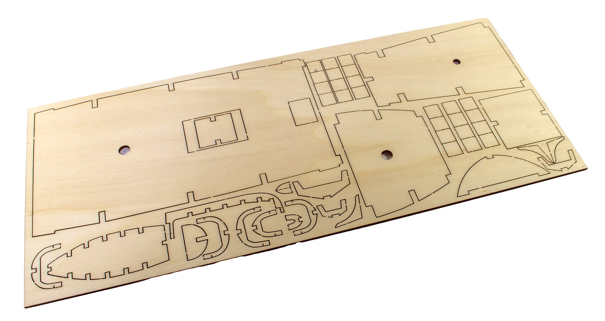
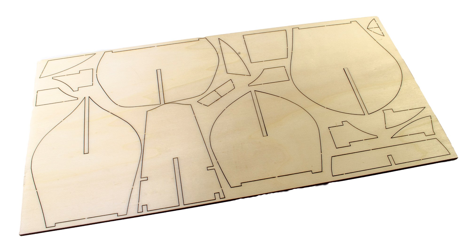
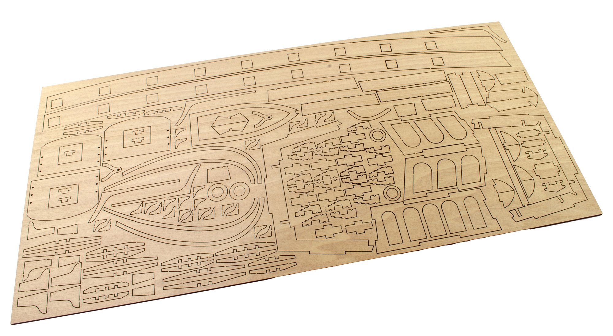
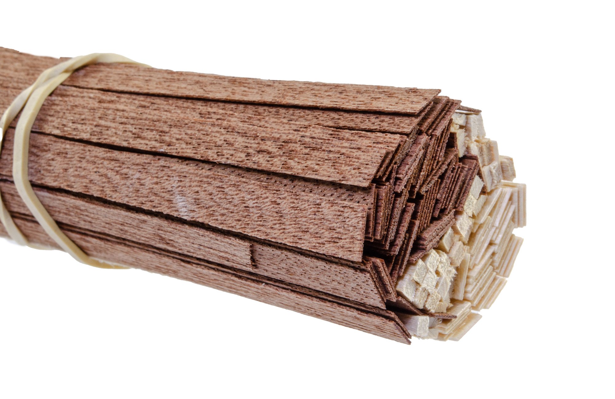
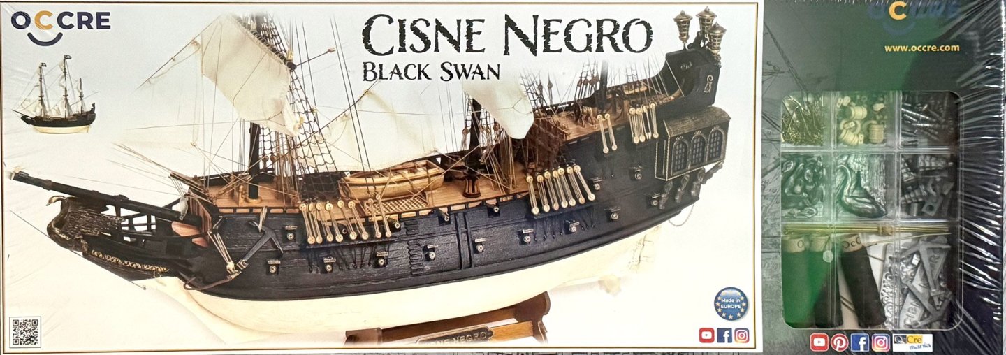
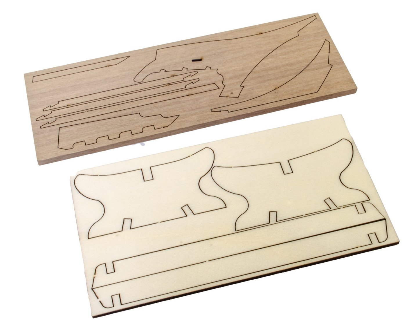
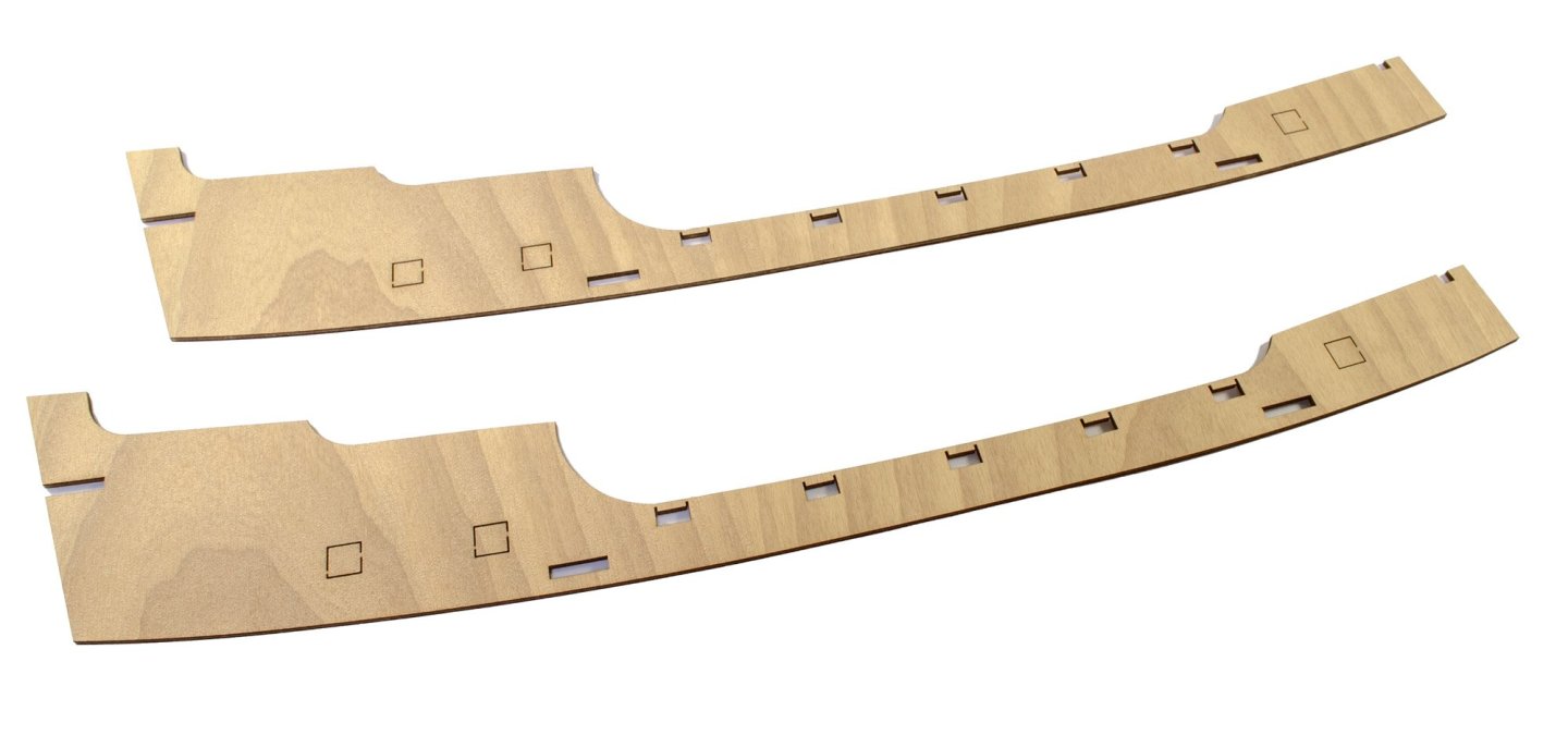
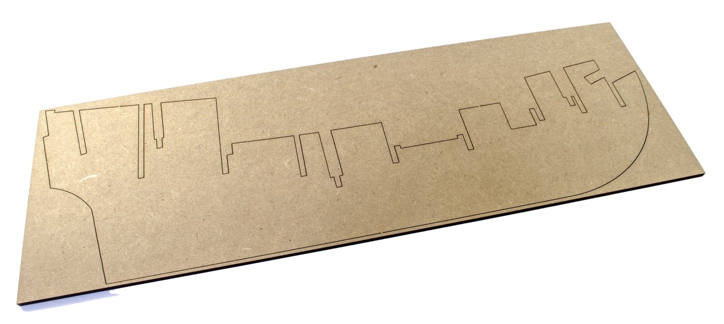
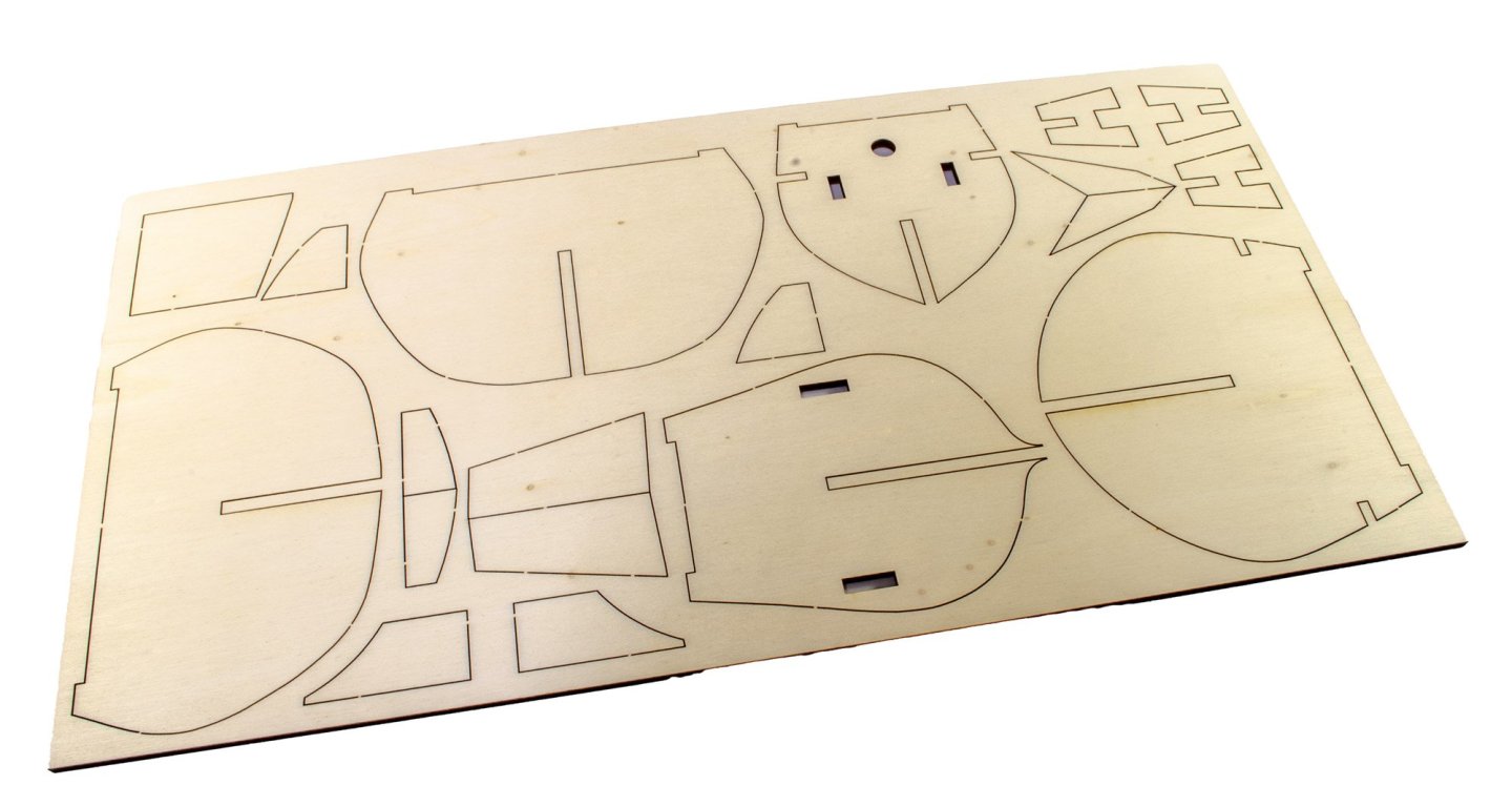
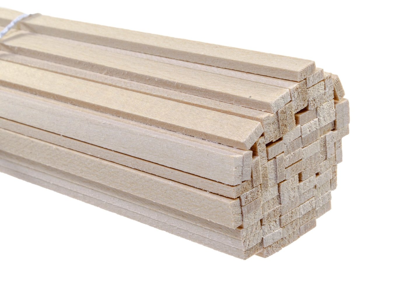
1:75 Black Swan OcCre Catalogue # 12012 Available from OcCre for £215.99 During the golden age of piracy, the Black Swan sailed the perilous waters of the Caribbean, leaving behind a trail of fear and admiration. Under the command of the ruthless Captain Tom Leach, this legendary ship raided Spanish trade routes and boldly faced fleets that tried to stop it. Its dark silhouette and black sails billowing in the wind were symbols of defiance, freedom, and adventure. OcCre's kit is a fictional vessel, inspired by Rafael Sabatini's novel of the same name, and the 1942 film. "From the coasts of Jamaica and Tortuga to Hispaniola, this ship is one of the most emblematic figures in the naval history of the Caribbean." The kit OcCre's kit is packaged in the same size box that Fram used, and several other of their kits that I've looked at here. This is a generic package, with a cutout that showcases the clear plastic fittings box. A large product label is fastened to the rest of the lid. When the lid is lifted off, the lower carton is folded inwards on itself to secure the contents. All of the timber/ply sheets are sealed with cellophane and didn't appear to have any warp or twist in them. The first sheet out is quite obvious. You can see from the MDF sheet that there are ten bulkheads along its length. The bulkheads are on two separate sheets and are made from ply. A few other parts are on these sheets too, such as the mast steps and various fairing blocks. One sheet here contains the parts for the cradle/display stand. This is made from ply. The top sheet contains the prow, keel and rudder post. This is produced in solid timber. This sheet of ply holds the four deck sections (including beak deck), and the various parts that go together to make the ship's launch. This is the sheet which holds all the details, such as rails, cannon carriages, etc. but also things like the mast tops and the lower run of cannon ports, on a single strip. Also on here you'll see galleries, channels etc. Laser cutting is excellent. Notice that these sheets don't have part numbers engraved. You'll need to cross reference the instructions for those details. Single piece upper bulwarks are supplied in ply. The quarterdeck upper edge has the ports with a temporary piece in situ so the edge stays straight during the most vulnerable part of the hull construction. Other ports are completely filled and just need the centres cutting loose. There are three packs of timber strip/dowel in this kit. The hull is planked in lime and then the dark, thin veneers are applied. I feel quite nostalgic when I see this as my San Francisco kit was constructed in the same way. The strip wood and dowel are nicely cut, with no fuzzy edges or warp in the parts.....quite important for the dowel! .....more soon.


-
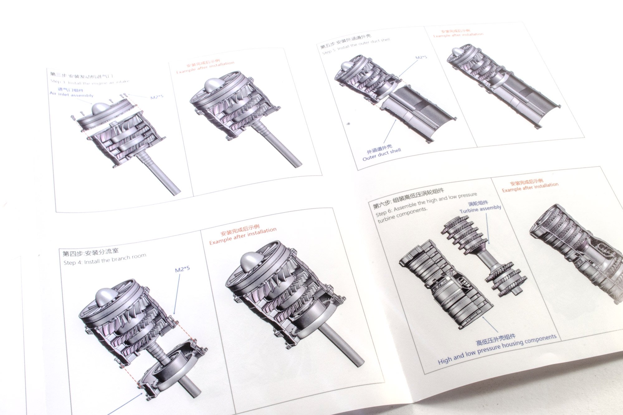
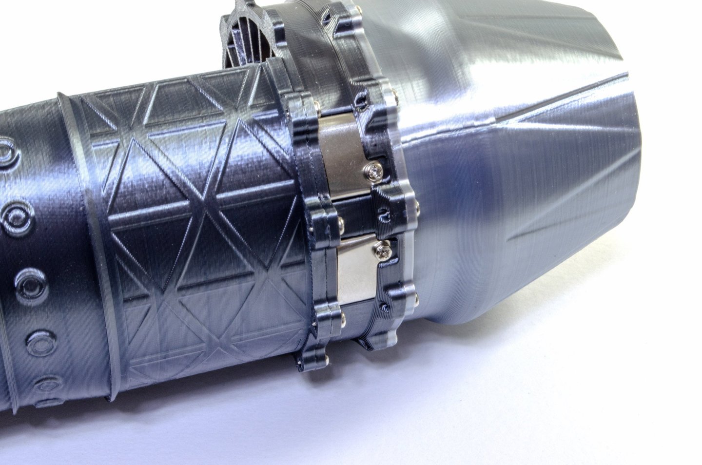
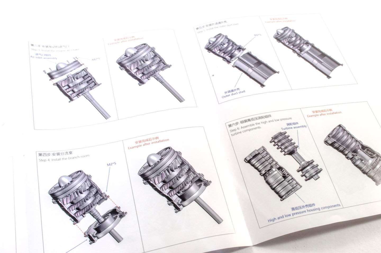
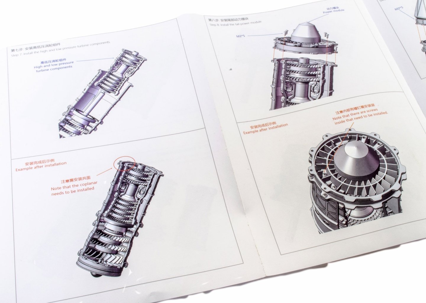
With the front screwed into place, the unit that the instructions call the 'diverging room' is now screwed to the rear of this, complete with another bearing. I'm not convinced about that unit name, but hey, it all fits together very, very smoothly. The outer duct shell is now screwed onto our assembly. Of course, this aligns with the cutout in the main unit. The five stage compressor and high pressure turbine housing is now clipped into the shell, again using a little prising of the plastic, and this unit is slotted into the main jet engine, ensuring alignment. This unit is called the 'tail power module', which is a good description as this is where the engine will derive its power, strangely enough! This fits in a certain way, so the metal power contacts are positioned as in the second picture down. Finally, the tail cone is screwed into place, and that is it! The base unit comes complete with a set of batteries. The switch is also on the underside, which isn't really the best design as you need to remove the engine from the base to operate the switch. With the switch 'on', the engine is sat on the base, making sure the contacts on the engine seat with those on the base. The engine is immediately powered. Here you can see the engine in operation with the fan blades blurred. Also, the tail exhaust has red lighting to give a sense of power. There is no sound on this model, but I'm glad, to be honest. Conclusion Without a doubt, this is the simplest and quickest engine I've built so far, but that's no bad thing. This model was great fun to build and there's still a sense of satisfaction to see it operating. If you want a relatively cheap, dead simple to build, and very attractive little project to sit on your shelf or desk, then this is defintelyone to go for. A total novice could build this with no issues. The overall quality can't be faulted, and I really do recommend this gorgeous little model! My sincere thanks to EngineDIY for sending out this kit for review on Model Ship World. To buy directly, click the link at the top of this article.


-
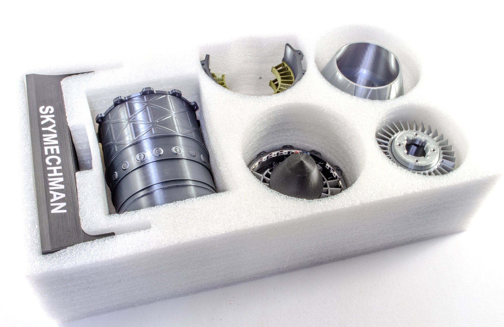
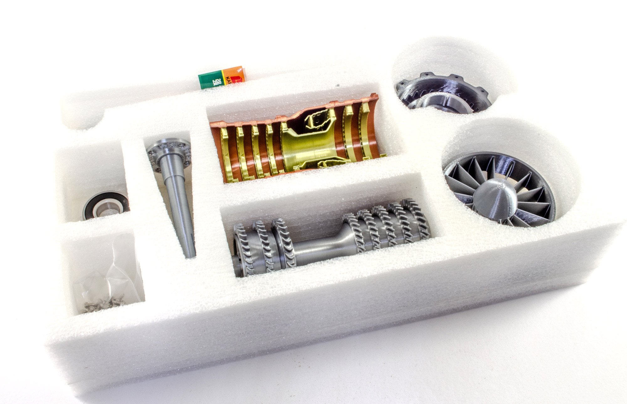
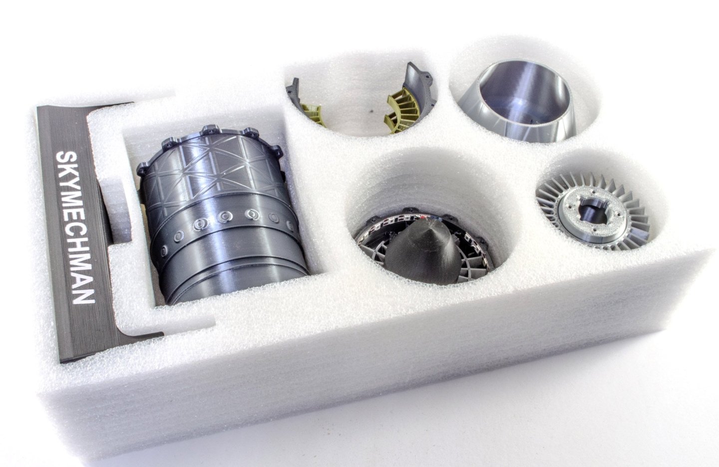
1:18 WS-15 Turbofan Engine - SKYMECH - via EngineDIY Available from EngineDIY for $89.99 The Shenyang WS-15, codename Emei, is a Chinese afterburning turbofan engine designed by the Shenyang Aeroengine Research Institute, and manufactured by the Shenyang Liming Aircraft Engine Company. The WS-15 is intended to become the main engine of the Chengdu J-20 stealth aircraft, enabling it to super-cruise, improve its range, manoeuvrability, and upgrade potential for future weapon systems. It will eventually replace the Shenyang WS-10, which currently serves as the interim engine of J-20, while the WS-15 is being refined. Delivery of the Chengdu J-20B fighter aircraft, which will feature the new engine, to the Chinese armed forces could begin in 2025. Development of the WS-15 afterburning turbofan engine began in the early 1990s. In 2005, the engine performed successfully on the testbed. An image of the core appeared at 2006 China International Aviation & Aerospace Exhibition. In 2009, a prototype achieved 160 kilonewtons (36,000 lbf) and a thrust-to-weight ratio of 9. The thrust target was reported as 180 kilonewtons (40,000 lbf) in 2012. Abridged from Wikipedia The kit This is a surprisingly lightweight package with very simply line illustration and 'Jet Engine' given as the product name. The website does show this to be the WS-15 turbofan engine as mentioned above. Opening the box reveals just two deep trays of parts for this build, and unlike the Trent-900 I recently reviewed, there are more pre-built assemblies in this kit. In fact, the whole model took about 45 mins to build, and that's including my photo and test time. Don't let that out you off though, as this is a fun build! All parts are made from 3D printed plastic, and in various colours. There are a number of print lines, but to be fair, they don't detract, with parts made in various metallic colours. Also included are some screws and a screwdriver. The only parts that aren't plastic are some bearings to help smooth operation. The instructions come in the form of a simple printed and folded sheet, with only ten stages from start to finish. These are very simple to follow and will present zero problems for the builder. Work begins on the 'three level fan' unit. This is supplies a complete unit, and you simply need to screw the main shaft onto it. The outer housing for this unit is now fitted. All I did to fit this was gently prise the housing, and the fan assembly popped into place very easily. As you can see from the photos, the 3d printing is exceptional and looks very good. The air inlet assembly is now screwed into place. Note that this has a bearing which provides smooth drive at the front of the engine. More in a moment... ssss


-
I don't, unfortunately. I also don't have the ability to 3d print.
-
I think somebody mentioned those to me but they aren't defined enough. The rivet heads are quite shallow. I used the same transfers on a spitfire I built about 10yrs ago.
-
It's outstanding!
-
Exactly, that's why I'd ideally want something I don't need to shape and doesn't need to be treated. I'd give up the will to live if I needed to paint 1000+ rivets 😆
-
Cheers. That's exactly the sort of thing I'm after, but the cost is prohibitive. They want £8.80 for only 60 rivet. I probably need a couple of thousand. I've not counted, so even if only one thousand, it would be expensive.
-
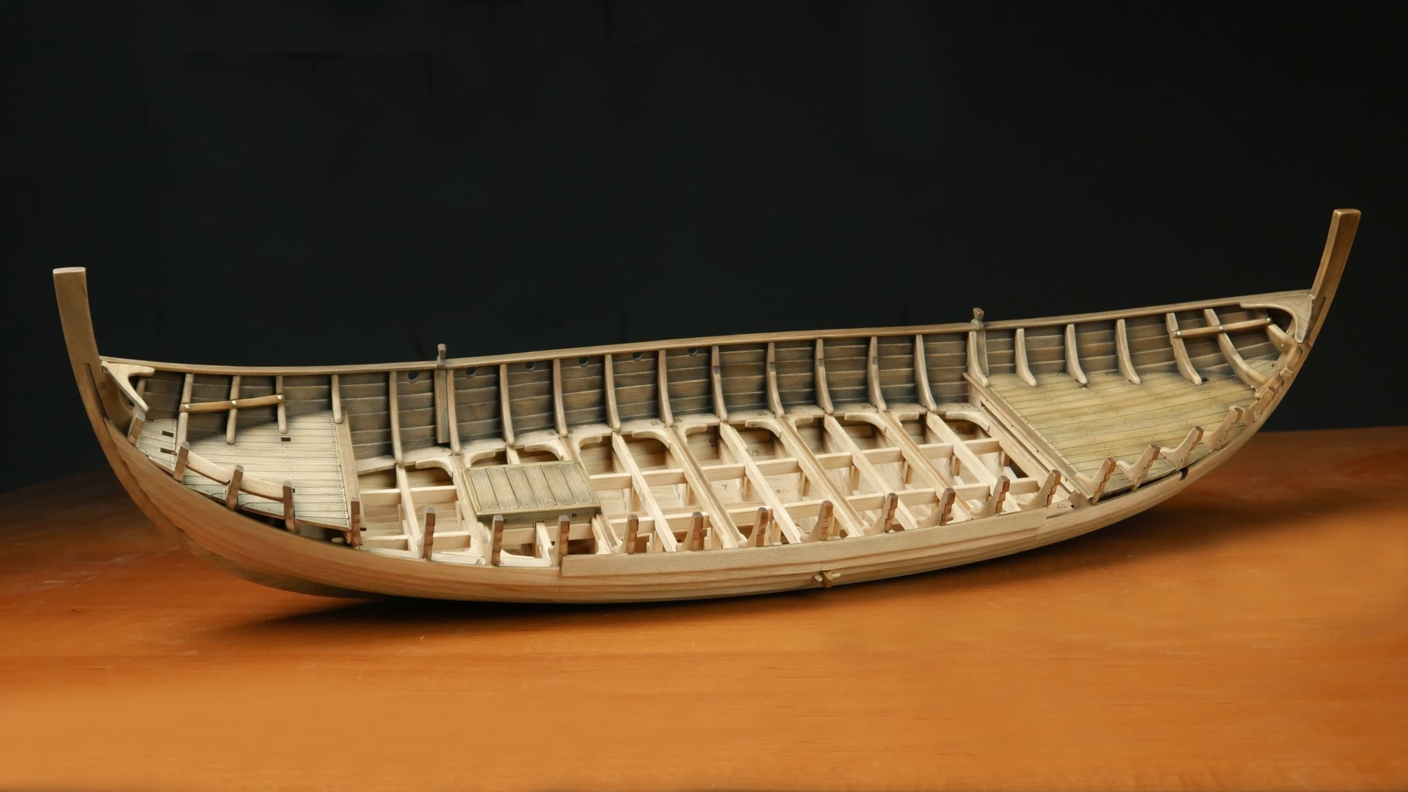
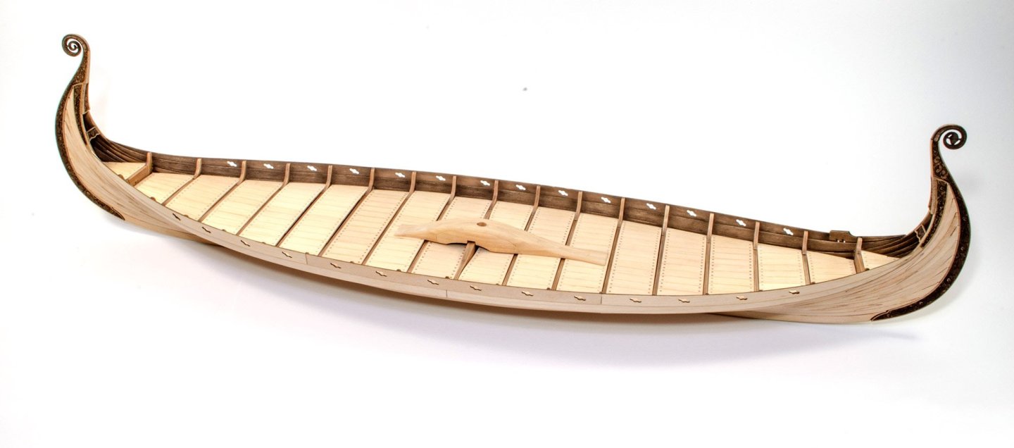
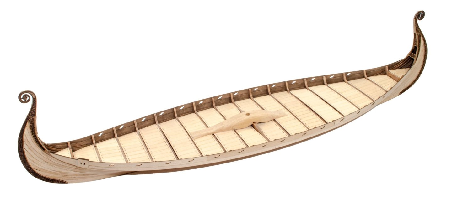
One thing I'd like to do with this model is to add the nails to the outside. This will need a LOT of nails. The best thing to use would be domed resin rivets, preferably in black resin. These would be perfect for something like this. A ship like Oseberg would have nails spaced about 200mm apart, equating to only 8mm apart on the model. So you can see I need lots of these. Question...does anyone know where I could get something like this? I don't want to use blackened brass nails.
-
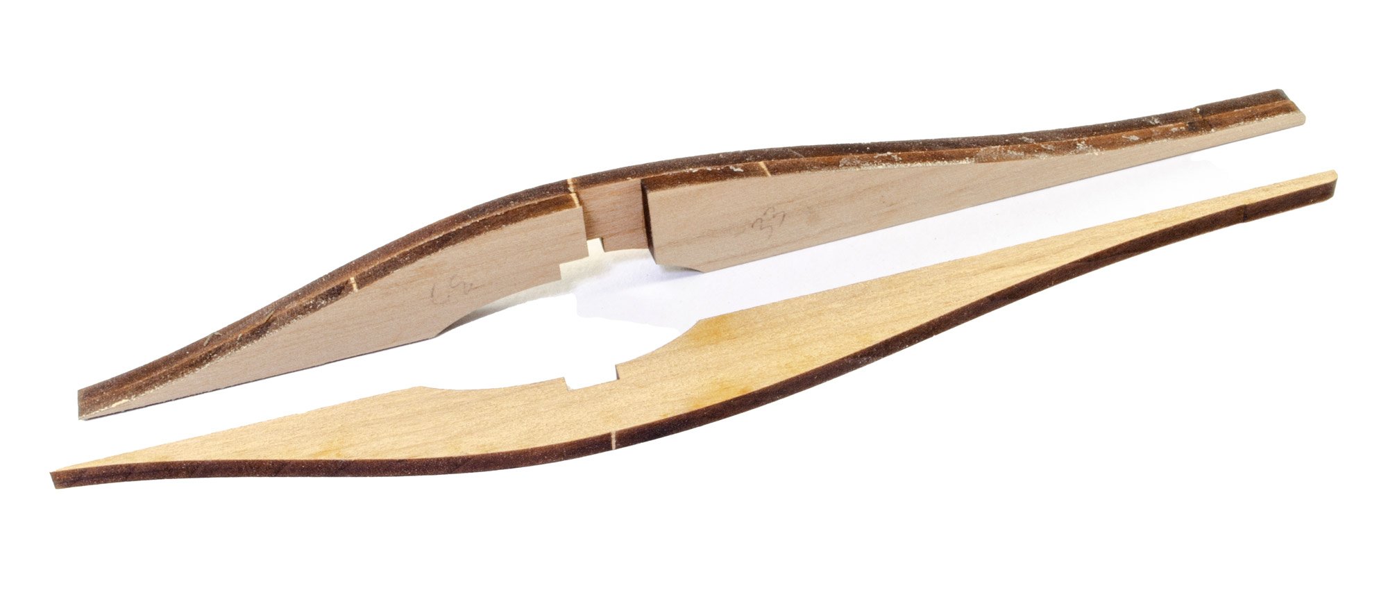
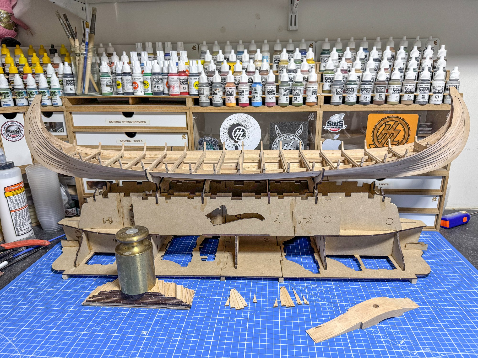
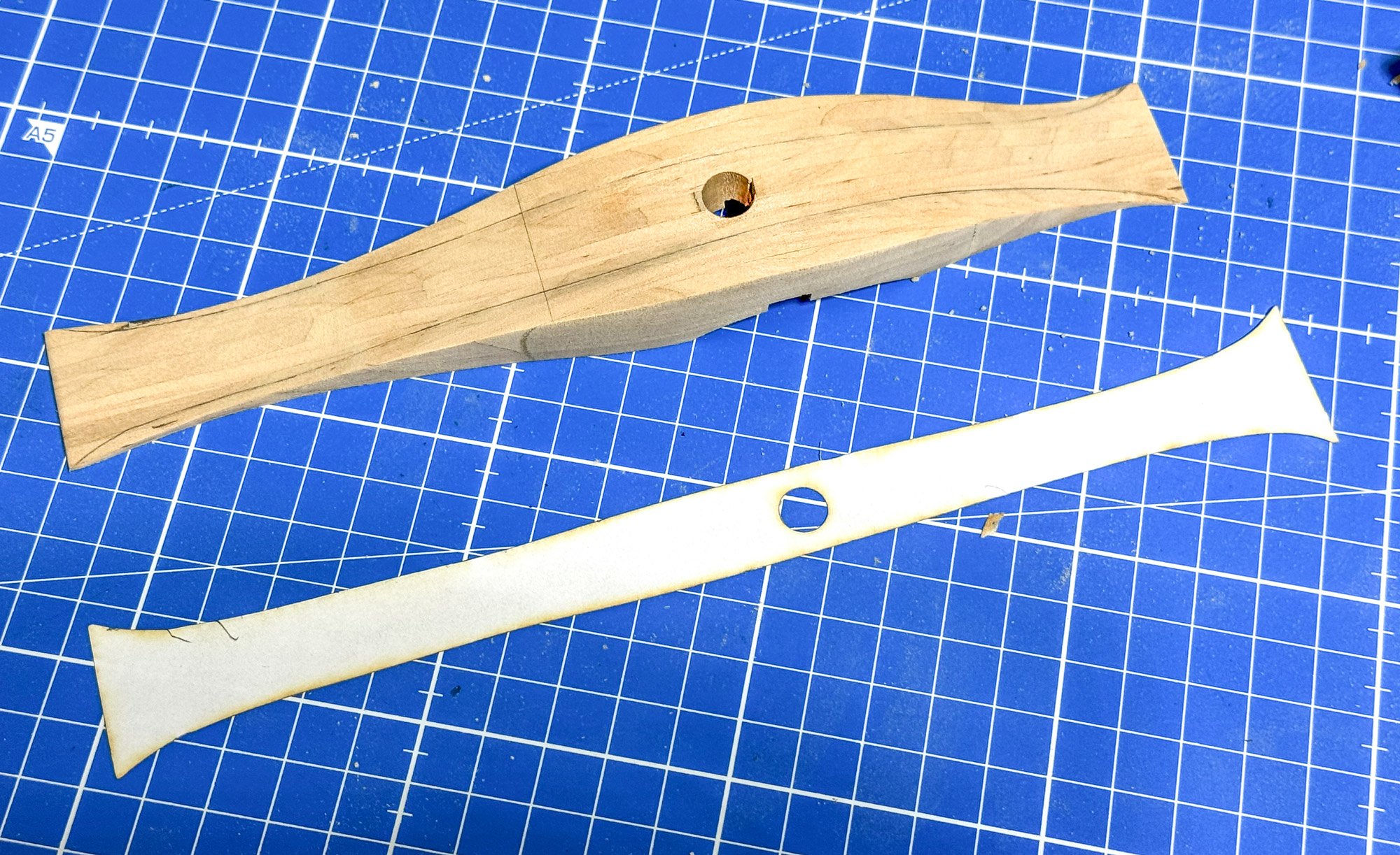
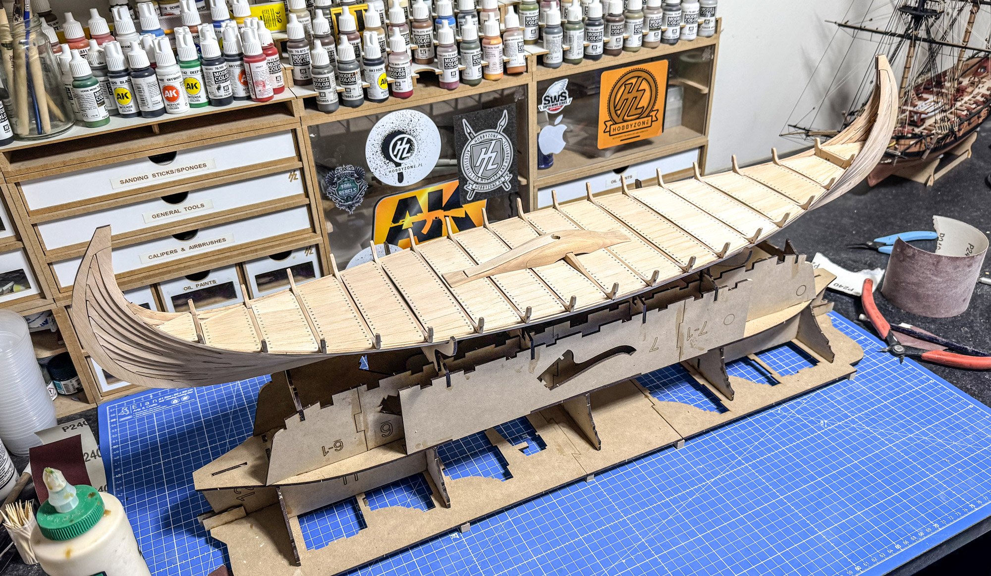
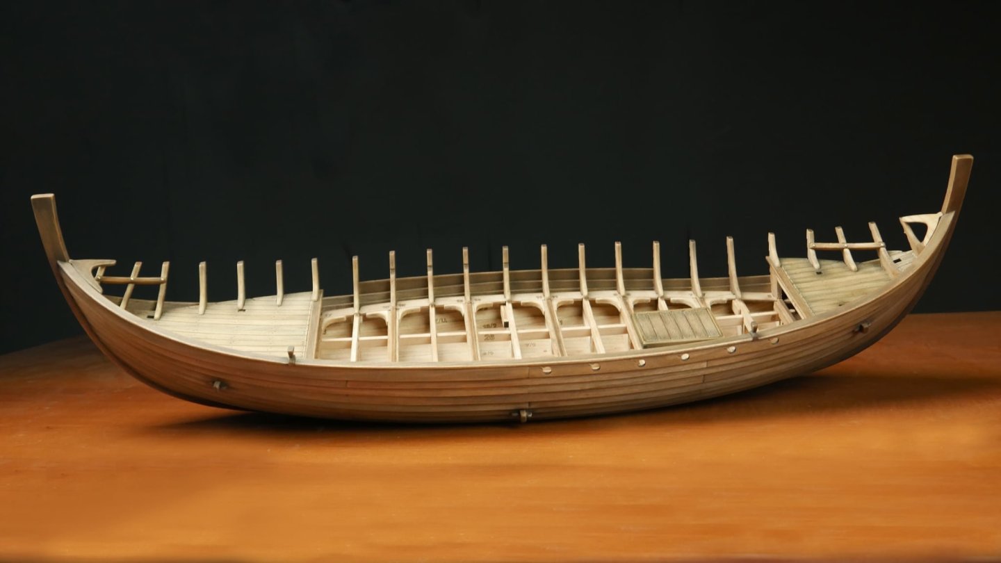
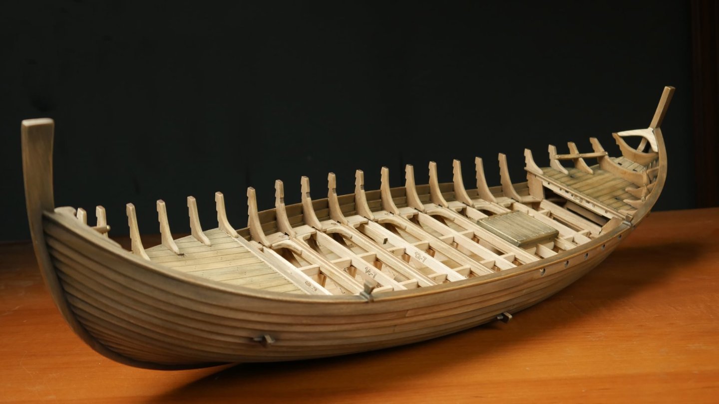
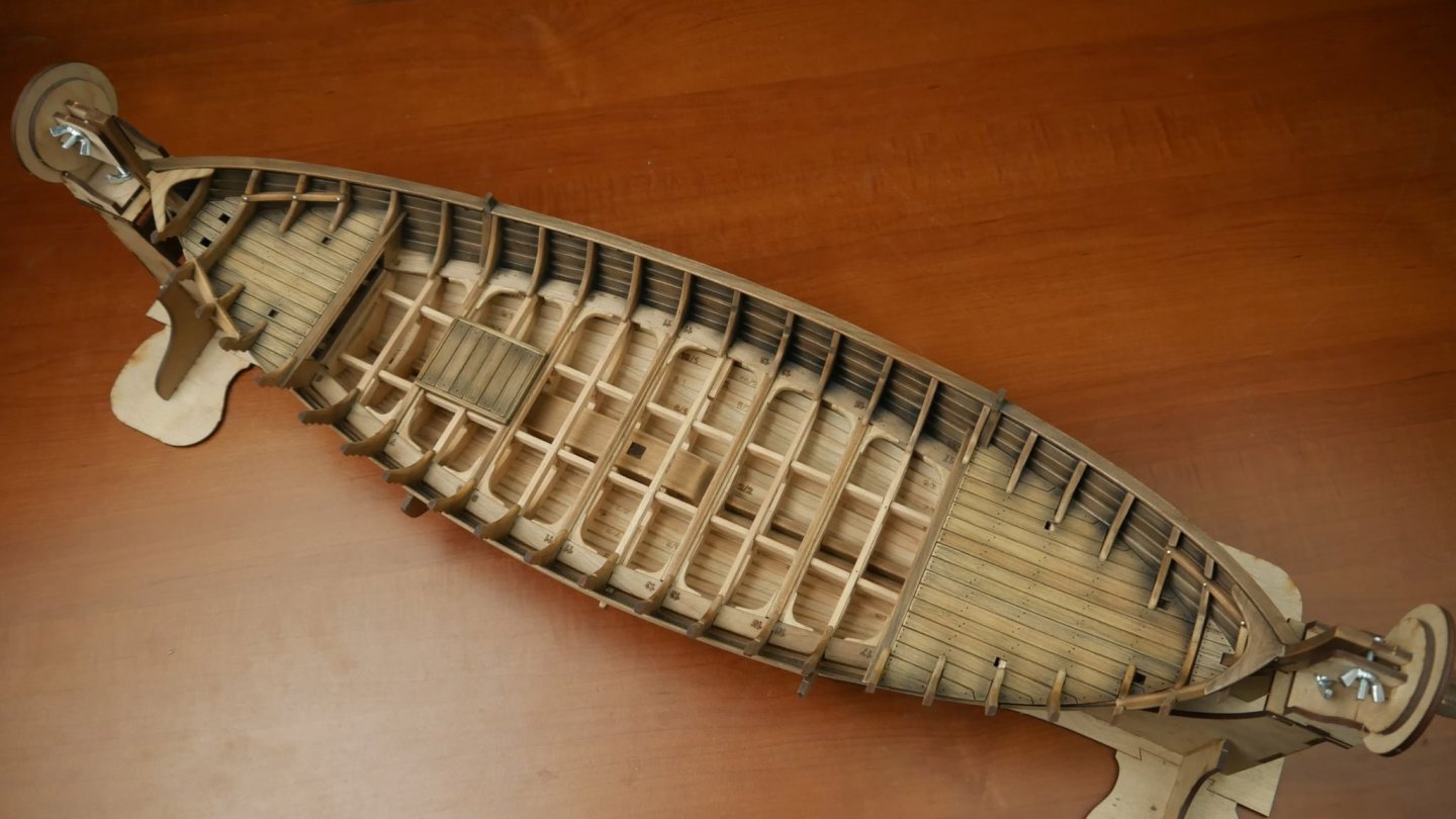
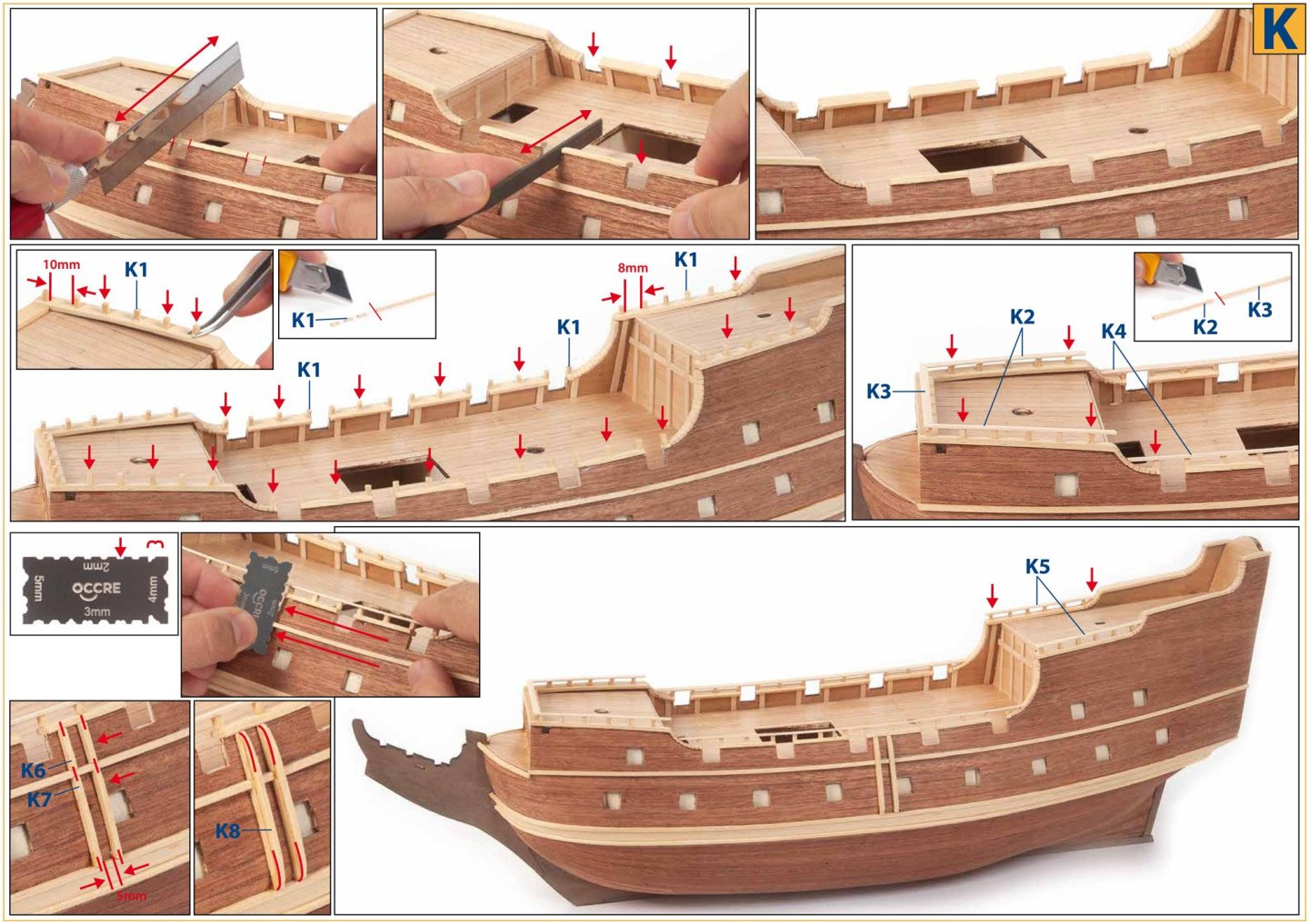
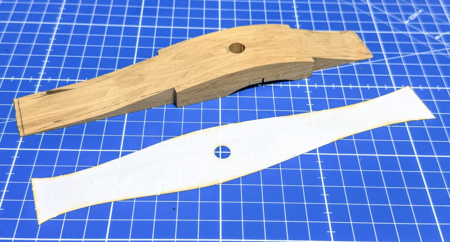
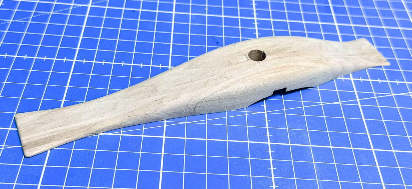
It's been almost 2 weeks since my last updates, and this might not seem like a lot, but I've certainly put a lot of hours in. The more visible things are the construction of the mast base, and also a full set of deck sections. Less obvious are the small changes and tweaks I've made to the hull, here and there, just so I'm happier with it. The mast foot is made out of several laminations of beech. All of these are glued up so there's a slot in the middle. What I did do was fill that slot with scrap timber and then drilled and reamed out the 9mm hole on a milling machine. Here you can see the mast base, sanded smooth to remove all the char. you can see it still needs shaping. Also here are the stack of deck sections, all finished wit 320 grit sand paper and then tweaked so they fit the hull. There are, in certain areas, very minor differences, so the deck sections are specific to their position. The edge margin timbers are bevelled on the underside so they don't foul the hull inner sides. The deck sections are provided as just that....sections, but you need to snap them apart like blocks of chocolate, then remove the edge char and bevel the top long edge. These are then glued back together to create infill sections for between the bulkheads. A little bevelling here and there, and they fit very well. The finished sections are bowed across their width, as you'll see, but they sit nice and flat with a gentle push. There are two paper templates. The first one dictates the upper profile. This is sat on and then traced. The assembly is then cut on a Dremel Moto-Saw. The second template is then traced. This creates the outer zone that needs to be shaped/rounded to finalise the shape. Here you see the mast foot sat in place, complete with the beech mast release part which has been soaked and clamped to the foot, to create that curve in the part. Also notice my bowed deck sections. They'll be just fine when glued down. The next job are some final woodwork tweaks and then onto some airbrushing.


- 48 replies
-
- 11
-