
Supplies of the Ship Modeler's Handbook are running out. Get your copy NOW before they are gone! Click here to order
×
Special NRG Webstore Information - See NRG News and Information
×


Mark P
-
Posts
1,763 -
Joined
-
Last visited
Reputation Activity
-

 Mark P got a reaction from DaveRow in Basic Question on the Placement of the Wales
Good Morning Everyone;
Some interesting thoughts are being added to this debate. However, although some are correct, and some somewhat less so, nobody has yet stated the truth regarding the reasons for adding wales to a ship. They were structural members, yes, and important ones; and they evolved over time from a number of single, relatively parallel strakes of timber into broader bands made up of several strakes together.
However, the main intention and function of wales was to counteract 'hogging', also called 'reaching'. This was the perennial problem of timber construction, wherein as a wave passes under a ship from end to end, the stern and bow in succession are left unsupported, and tend to droop. Over time, this led to the butt joints of the planking opening up, and to the keel becoming curved downward at each end. Warships were especially prone to this, due to the weight of the ordnance carried at bow and stern.
The wales were separate strakes of heavier timbers, inserted in the planking, running parallel to the external planks. Although not always specified, they were often bolted to the timbers, not treenailed, for additional strength (remember that iron bolts were expensive, and were not used lightly)
In order to achieve the maximum benefit of this method of strengthening, the curvature of the wales was exaggerated relative to the sheer of the deck, so that the ends of the wales were higher relative to the line of the deck, than was the case amidships.
The main wales were always sited so that they gave strength to the main deck, being in line with it at the midships, and above it at the bow and stern.
As Druxey states above the decks were, in earlier times, stepped downwards at the end, in order to avoid the need to cut gunports through the wales, thereby weakening them. However, it was realised that this significantly weakened the resistance of the deck planking to hogging, and it was already recommended in England that steps should be avoided, by 1612.
The internal planking, though, did follow the sheer of the decks.
The essential principle of internal planking was that at every location where there was a line of overlap in the ship's timbers, between floor timbers and futtocks, for example, and different ranks of futtocks, this overlap was strengthened with a much thicker band of planking, in many locations, and with quite a variety of names: for example, what in later times was known as 'spirketting', that is the run of thick timbers between the waterways and the gunport cills, was originally known as the 'spirkett wale'. This is because the spaces between the ends of the timbers were known as 'spirketts'.
Others were 'sleepers'; 'middle bands'; and 'footwaling'. In later times these became known under the more generic term of 'thick stuff over the futtock heads'.
In order for the wales of the model which started all this to look realistic, it is necessary that they must follow the sheer of the planking.
All the best,
Mark P
-
 Mark P got a reaction from Archi in Was ship's painted in the UK back in 1600's ?
Hi Tom;
I would be very careful before giving too much credence to anybody who talks of Navy ships from the early 1600s being 'HMS'. This was a term which came into use much later. In the 17th century ships were always known as 'The' whatever. So Mayflower was called 'The Mayflower'.
Prestige ships, or 'Ships Royall', were certainly painted beautifully, and gilded. Check out the painting of the 'Arrival of the Elector Palatine at Flushing' and other similar ones, which will give a good idea of what was normal for some ships in those times (the Elector had just married King James I's daughter, sister of Charles I, and returned to Europe in the King's best ships) It is probable that any captain with any self-respect would try to do his best for his vessel, but Louie's comments in post no 4 above are certainly worth keeping in mind also. At the end of the day, nobody knows, so do as you wish!
All the best,
Mark P
-
 Mark P got a reaction from FrankWouts in HMS Bellona 1760 by SJSoane - Scale 1:64 - English 74-gun - as designed
Good Evening Mark;
I am very glad to see that you are posting again, and that you are at such an intricate, complicated stage of the work. Quarter galleries are a tremendously difficult area to do well, but they are one of the first parts to catch the eye when looking at a model; so it is vital to be absolutely happy with each stage, and to discard what does not meet your exacting standards. I don't doubt for a moment that yours will up to your usual extremely high level of excellence; a standard nearly all of us can only aspire to, and never equal.
I wish you all success and good health in continuing what you have begun in such an exemplary tour-de-force.
All the best,
Mark P
-
 Mark P got a reaction from daHeld73 in HMS Bellona 1760 by SJSoane - Scale 1:64 - English 74-gun - as designed
Good Morning Mark;
With regard to port stops, Druxey & I, and others, have had some lengthy discussions on the subject, which I feel fairly confident in saying settled the matter to the satisfaction of most, which was that no additional timbers were added to the sides/tops/bottoms of ports, and that the stops were formed by ending the planking short of the sides of the openings. Perhaps Druxey can point you to these posts should you wish. It is beyond my skill level, unfortunately.
All the best,
Mark P
-
Mark P got a reaction from daHeld73 in HMS Bellona 1760 by SJSoane - Scale 1:64 - English 74-gun - as designed
Good Morning Mark;
One thing to keep in mind with planking is that where a continuation of the plank above a gun port would leave only a thin sliver of the next-below strake running over the gun-port, the plank above would often be widened in the vicinity of the port, so that it extended downwards and occupied the position of the below strake. The technical term for this was 'to give wood to the ports', which is frequently mentioned in building contracts. Whilst I have seen planking expansions showing this, I cannot at present remember where I saw one to include here for you. It was done by drawing a line at 45 degrees upward and outward from the top corners of the port, until this line intersected the lower side of the strake above the port. The area thus delineated was included as part of that strake.
Also, as Druxey mentions, butts above or below gun-ports were specifically avoided.
All the best,
Mark P
-
 Mark P got a reaction from Kenneth Powell in HMS PEGASUS by giampieroricci - Scale 1:36 - Swan-Class Sloop from plans by David Antscherl & Greg Herbert
Giampiero that is a most beautiful model, I congratulate you on a great achievement!
The tidiness of your workshop is almost as impressive also!
All the best,
Mark P
-

-
 Mark P got a reaction from mtaylor in HMS PEGASUS by giampieroricci - Scale 1:36 - Swan-Class Sloop from plans by David Antscherl & Greg Herbert
Giampiero that is a most beautiful model, I congratulate you on a great achievement!
The tidiness of your workshop is almost as impressive also!
All the best,
Mark P
-

 Mark P got a reaction from giampieroricci in HMS PEGASUS by giampieroricci - Scale 1:36 - Swan-Class Sloop from plans by David Antscherl & Greg Herbert
Giampiero that is a most beautiful model, I congratulate you on a great achievement!
The tidiness of your workshop is almost as impressive also!
All the best,
Mark P
-
 Mark P got a reaction from billocrates in HMS PEGASUS by giampieroricci - Scale 1:36 - Swan-Class Sloop from plans by David Antscherl & Greg Herbert
Giampiero that is a most beautiful model, I congratulate you on a great achievement!
The tidiness of your workshop is almost as impressive also!
All the best,
Mark P
-
Mark P reacted to Remcohe in HMS Kingfisher 1770 by Remcohe - 1/48 - English 14-Gun Sloop - POF
After a long (way too long) interruption my Kingfisher is back on the bench. I have still been busy modelling but with other (plastic related) topics not fit to portray here, still it was al lot of fun. But it was time to return and make some wood dust again. So over the past few week I managed to get back into the build, did a lot of head scratching trying to remember where I left of and more important how things were done. Some of the procedures got lost in time and I have to figure out again.
After taking the model out of storage ( it was stored in a dark place) I noticed a few things, the boxwood turned darker, the holy I used for the lower deck planking turned dark almost to the color of the boxwood. The wale that was stained with Fiebing ink turned much lighter. Overall a few cracks have appeared between the outside planing, but nothing too serious. Not bad after 5 years in storage and moving 3 times to different locations.
So the upper deck spriketting and quick work was finally finished. I did not dare to drill holes for the scuppers as I'm afraid the inside and outside planking is not completely aligned the way it should be and the suppers might hit the wale.
Upper deck planking installed and treenailed. I used thin black paper for caulking.
The fixed blocks were remade as the previous ones had fitting issues. I decided to make them from one piece and carve the sheaves in situ. Unfortunately I discovered too late that the wood I used for the double block was much lighter. Now it looks like it was an off site repair job.
Whilst working with plastic and specifically with Gundam models I picked up there plastic scribers. They also function as great mini chisels for wood. They come in many sizes and are super sharp. Due to the high angle of the blade they cut very aggressive in wood so care must be taken but a great addition to my woodworking toolset.
Remco
-
Mark P got a reaction from daHeld73 in HMS Bellona 1760 by SJSoane - Scale 1:64 - English 74-gun - as designed
Good Evening Mark;
Thank you for taking the initial steps with photo-etching, so that those who come after can learn from your experiences, and most importantly, any mistakes!
Keep up the great posts!
All the best,
Mark P
-
Mark P got a reaction from daHeld73 in HMS Bellona 1760 by SJSoane - Scale 1:64 - English 74-gun - as designed
Morning Mark;
You are correct about the ring on the cascabel for the breeching rope. It appeared around 1790, I believe.
Prior to this, on some ships, a thimble was seized in a short strop around the cascabel to provide an eye for the breeching rope. The thimble was placed above the cascabel.
All the best,
Mark P
-
Mark P got a reaction from daHeld73 in HMS Bellona 1760 by SJSoane - Scale 1:64 - English 74-gun - as designed
Evening Mark;
Yes, this is an awkward little spot. You are right about the little triangle, which abuts the rear face of the wale planks on the outside; the side of the final curved end of the bottom planking on the inside; and sits under the counter planking at the top. This latter seam is then covered with the tuck moulding.
The end of wale is rounded on its bottom corner to fair in with the curve of those last few inches of bottom planking. ie the bottom end of the wale is a curve when viewed from abeam.
The amount of curvature required is controlled by the vertical difference between the height of the bottom of the wale, and the underside of the tuck mould. This distance seems to vary from ship to ship. In Endymion, below, it is perhaps greater than in some others, producing a larger radius curve than you will need to use for Bellona.
It might be the angle of your picture, but it seems that you might not have left the counter planking with an edge for the bottom planking to butt against.
The last little curved part of the bottom plank which is against the triangle was often sawn from the solid.
The pictures of Endymion below show it quite well.
All the best,
Mark P
-
 Mark P got a reaction from davx57 in HMS Bellona 1760 by SJSoane - Scale 1:64 - English 74-gun - as designed
Good Evening Mark;
I am very glad to see that you are posting again, and that you are at such an intricate, complicated stage of the work. Quarter galleries are a tremendously difficult area to do well, but they are one of the first parts to catch the eye when looking at a model; so it is vital to be absolutely happy with each stage, and to discard what does not meet your exacting standards. I don't doubt for a moment that yours will up to your usual extremely high level of excellence; a standard nearly all of us can only aspire to, and never equal.
I wish you all success and good health in continuing what you have begun in such an exemplary tour-de-force.
All the best,
Mark P
-
Mark P reacted to Chuck in Deadeyes
I disagree, Consistent and symmetrical deadeyes can make a world of difference whether rigged or not. These are 3D printed in the darker "swiss pear color" and lighter "boxwood color" are also available. It really shows when the deadeyes are grooved for the rigging between a pair of deadeyes so the ropes lay properly. With every little detail you can improve upon it will make the overall look of your model better. Switching out blocks and rope are an easy way to elevate a model although it does increase the cost. But a cheaper alternative would be to make your own if its at all possible.
-
 Mark P got a reaction from paul ron in About them 18th Century Cannon Balls?
Good Morning All;
The number of cannon-balls of each size was laid down in the Navy Board's standing orders, with quantities reduced for each smaller size of ship. When a ship was commissioned, the guns, powder and shot were all supplied by the Ordnance Board, and the ship's gunner had to check the quantity and was then responsible for all the stores issued. At the end of the commission, he had to account for, or return, everything which had been issued previously. As these stores were worth a lot of money, a strict inquiry was made for each ship. I have read of cases of powder being concealed behind piles of timber or under other stores in order to steal it (merchant ships or privateers were ready buyers) One ship, whose name I cannot remember, is believed to have been blown up when a stolen cache of powder was accidentally ignited.
All the stores were listed and named on a printed sheet several pages long, with the quantities entered by hand. One document was created at issue, and then updated on return of the stores. See sample below, dating from 1682.
Regarding the storage and movement of round-shot, the shot-lockers were located either side of the ship's well, directly under the successive layers of the main hatch and the after hatch on each deck. It would not have been difficult to rig a sling through either hatch and haul a net-full of shot up to whatever deck required it, which was the reverse of the method used when loading the round-shot from a delivery. Additionally, a quantity of shot was stored on each deck in racks, ready for use. The shot-lockers were divided internally to keep different sizes of shot separate. Each locker is approximately 9-10 feet tall, so they would have held a lot of shot.
See below an excerpt from a draught of a 74, showing the hatchways (the solid red, horizontal rectangles) and shot-lockers in line.
All the best,
Mark P
-
Mark P got a reaction from daHeld73 in HMS Pandora 1779 in 3D
Hi Jingyang;
The gammoning slot looks fine to me. I would round off the upper edge a bit, though, where the rope will otherwise lie against a sharp corner; and the same for the hole for the mainstay collar.
I wish you all the best progress in your project. If you ever need a second opinion on any part, please feel free to ask. I cannot say that I will know the answer, of course!
One other source of information, which you may have already tried, is Navy Board contracts. When pressures of wartime needed a large number of vessels to be built, some of them were built at the yards of merchant ship builders. Normally there would be a contract drawn up, very detailed, specifying the scantlings of nearly all the timbers, and the number and size of bolts, to ensure that the builder would adhere to Navy standards of construction.
With best wishes,
Mark P
-
Mark P got a reaction from daHeld73 in HMS Pandora 1779 in 3D
Hi Jingyang;
Research in contemporary sources is certainly the best way to find results, and is wonderfully interesting at the same time.
Your draughting shows that you already have a deep understanding of Pandora's construction, and if you have read such good authors' works then you have a good breadth of knowledge also, and I can add little.
From what I have seen, the construction of the knee of the head was largely the same for all vessels, it just varied in scale and the number of chocks used.
All the best,
Mark P
-
Mark P got a reaction from daHeld73 in HMS Pandora 1779 in 3D
Hi Jingyang;
Thank you for your reply. The level of your draughting skill continues to amaze me. I am competent with 2D CAD, but I could never achieve what you make look so straightforward.
To answer your queries:
The taper of the standard as compared to the knee of the head below it is now shown correctly above. However, the shape of the standard needs to be revised. It actually curves upward at its forward end, and is scarphed into a thin, curving extension piece, which extends up behind the figurehead. The upper edges of both the standard and the extension are given a small chamfer.
The rounding over I was referring to is to the timber right at the front of the knee of the head, below the figurehead. This should be virtually semi-circular. The cambered cladding piece which you show attached to the forward edge would not have been made so. Such thin wear pieces are attached lower down, where the leading edge is a hollow curve.
One last point is that the gammoning slot is cut in the head of the gammoning piece, which extends well down, and is the principal timber of the knee of the head. There would not be a horizontal joint below the gammoning slot, curving up as it goes forward. If you can, take a look at one of the excellent practicums by Ed Tosti or David Antscherl; or study a build log here looking for a part of the framing plan showing the knee of the head. They know far more about this than I do, and have illustrated it very well.
Again, if you are already aware of this, and it is just because I am looking at a work still in progress, please accept my apologies.
All the best,
Mark P
-
Mark P got a reaction from daHeld73 in HMS Pandora 1779 in 3D
Hi ppddry;
Absolutely wonderful draughting work. The level of detail incorporated is something that would reward many hours of studying your drawings, and there would still be more to find.
One very small point, given by someone who knows he can never equal what you have done here, but I hope you would like to know it, is that the knee of the head tapered forwards, and was much narrower below the figurehead than where it was bolted to the stem, which you show correctly. However, the standard in the head, at the top of the knee, was narrower, and almost parallel sided, and did not follow the taper of the timbers below it, leaving a ledge where the standard sat on the knee. The leading edge in the upper part of the knee was also rounded over, quite noticeably at the top, diminishing to nothing as it went down.
If this has been left as a chamfer deliberately, apologies for raising it before you have finished.
All the best,
Mark P
-
Mark P got a reaction from daHeld73 in HMS Bellona 1760 by SJSoane - Scale 1:64 - English 74-gun - as designed
Evening Mark;
I am not sure where the drawing came from, but just in case you are not aware of this, it is not accurate. My apologies if you already know, but the bottom of the spirketting is wrong on both decks.
The waterway has a hollow curve, but the spirketting is flat. It would waste an awful lot of wood and be a lot of work to produce it as drawn.
All the best, and keep up the inspirational work!
Mark P
-
Mark P got a reaction from daHeld73 in HMS Bellona 1760 by SJSoane - Scale 1:64 - English 74-gun - as designed
Alan, I am sad to hear that they are charging such silly prices. Presumably they mean that someone has to take it out and photograph it. That kind of money would start a small film studio, though. Especially in this digital age, when no-one has to develop or print it.
With regard to girdling, it dates back at least to the mid 1600s, and was commonly resorted to when a ship failed to float as high in the water as expected after launching.
All the best,
Mark P
-
Mark P got a reaction from daHeld73 in HMS Bellona 1760 by SJSoane - Scale 1:64 - English 74-gun - as designed
Evening all;
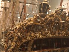
See attached a picture of 'Endymion' 44 guns, from the Royal Collection at Kew Palace
This shows a triangle of planking. It has to be a separate piece, as the wale would be very thick if it was part of it.
All the best,
Mark P
-
Mark P got a reaction from daHeld73 in HMS Bellona 1760 by SJSoane - Scale 1:64 - English 74-gun - as designed
Evening Druxey;
I think that it is actually not part of the planking at all, but the end of one of the model's ribbands, and so only a temporary piece (although it's been there several hundred years!)
OOPS! Apologies! Just looked at it again, and it is clearly part of the wale. Is the appearance of a joint close to the end just a trick of the light, though?
In the CAD picture it is certainly a separate piece, which would seem the most logical. It is, of course, not necessarily contemporary practice. I will look at some of my photos of contemporary models, and post anything which seems to shed light on this point.
All the best,
Mark P