_SalD_
-
Posts
853 -
Joined
-
Last visited
Content Type
Profiles
Forums
Gallery
Events
Everything posted by _SalD_
-
 @Ian_Grant, I think a little explanation is in order. I am currently at my residence in Florida; however, the earlier photos were taken in Connecticut, where they have snow and ice also, but the pool shown is indoors. My main workshop is also in Connecticut, where we spend the holidays with family and a few months during the summer. The ship is still in Connecticut, so I’ll need to wait until we return there in the summer before I can sail her again. I can work on some parts of the model while I’m down here, but I don’t have the space to keep the full model in Florida. Thanks for looking in.
- 79 replies
-
- 3
-

-
- Nordkap
- Billing Boats
- (and 2 more)
-
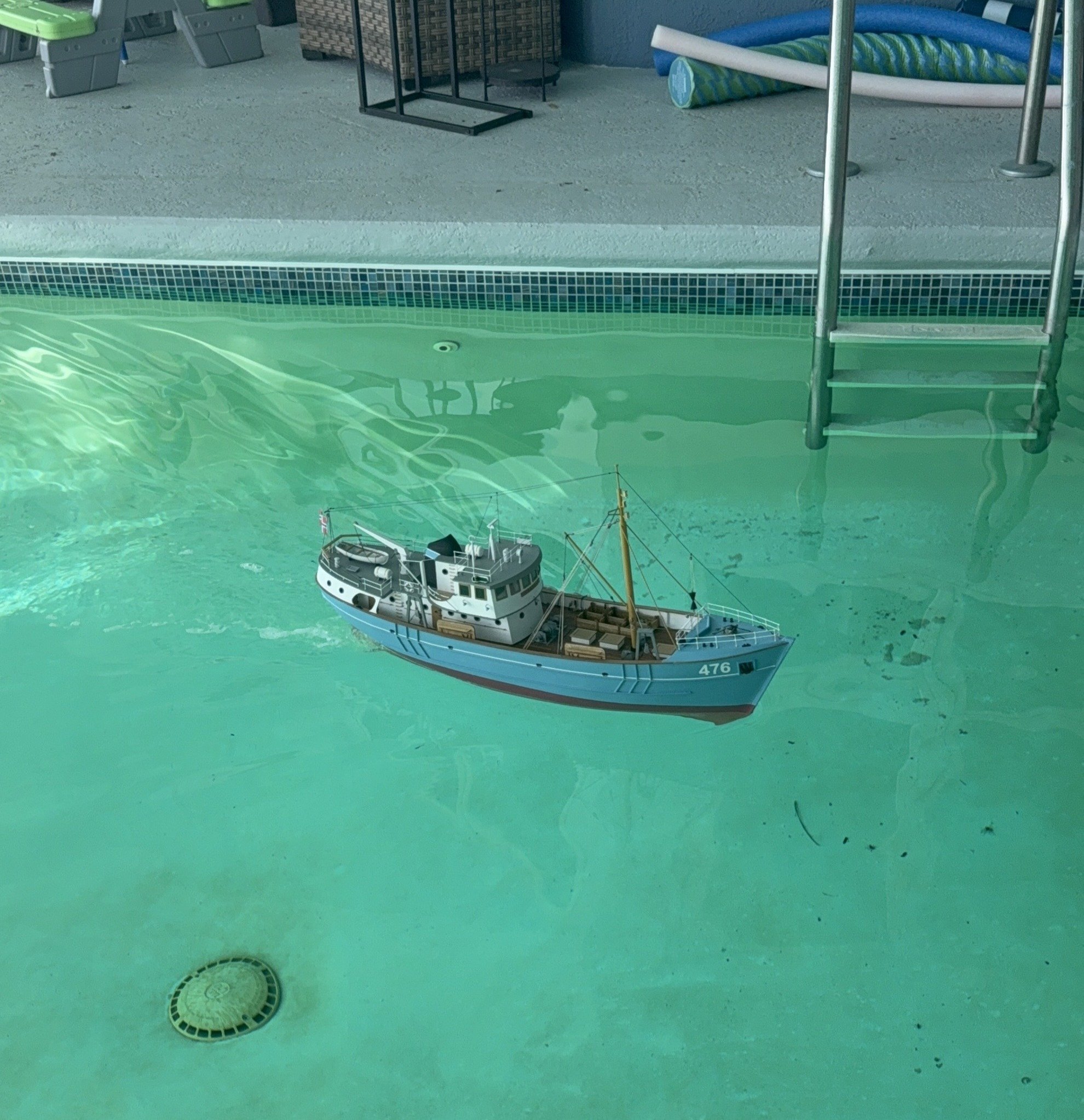
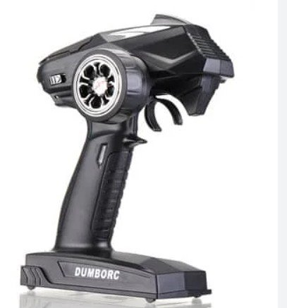
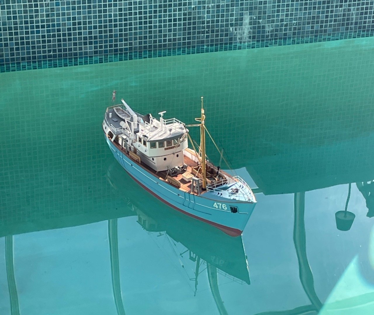
Not exactly a sea trial, but I’m taking baby steps. I used a friend’s pool to get a better feel for the controls and how the ship maneuvers. In a way, I’m glad I tested her in the pool first because it helped me work out a few kinks. I also wanted to try out the new transmitters I purchased—the Dumborc-6X. The first issue was a simple one: making sure the battery was fully charged. I put her in the water, made one lap around the pool, and the battery died. (Color me embarrassed.) 🫢 The next challenge was controlling the rudder movement and propeller speed. There was too much throw in the rudder servo, so I had to be careful not to turn the steering wheel too far to the left or right. The same issue showed up with the throttle—the forward speed was difficult to keep slow and steady. Later, after watching a YouTube video on the transmitter, I learned that you can limit both servo travel and maximum motor speed by adjusting the two knobs on top of the transmitter. These knobs control the percentage of maximum servo movement and motor output. (It takes me a while, but I eventually catch on.) I do have a video of this, but posting it here is above my pay grade.

- 79 replies
-
- 7
-

-
-
- Nordkap
- Billing Boats
- (and 2 more)
-
@robdurant, Rob, thank you so much for the kind words and for all your advice throughout my build. I truly appreciate your support. Wishing you all the best, and I hope you’re able to finish your Nordkap soon.
- 79 replies
-
- 1
-
-
- Nordkap
- Billing Boats
- (and 2 more)
-
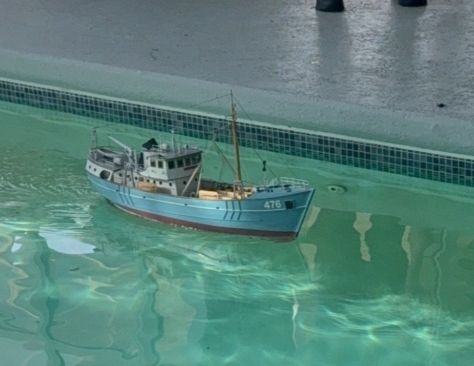
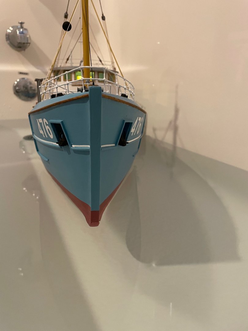
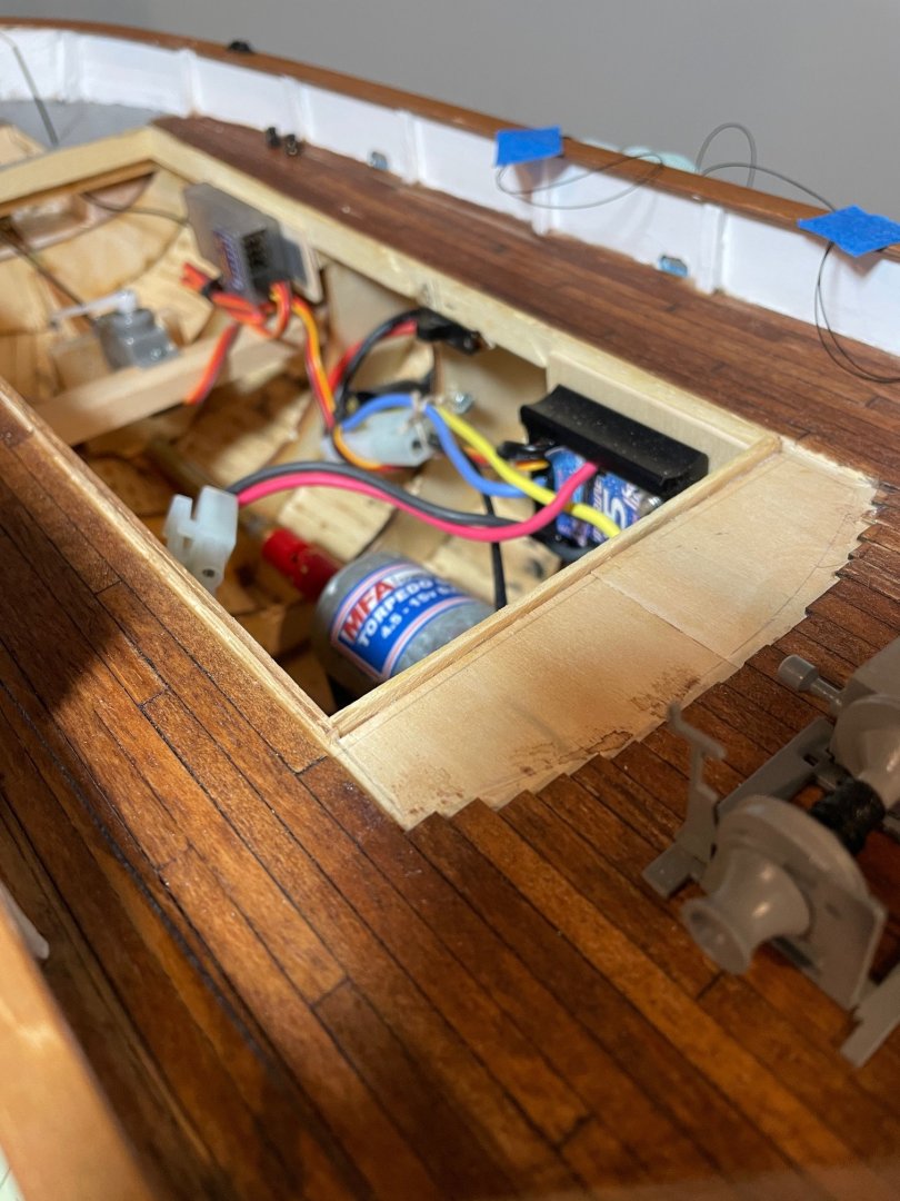
Finally, it was time for another tub test. With everything installed, including the battery, the ship was still riding high at the bow and listing to starboard. To address this, I added approximately one pound of lead shot between bulkheads 11 and 12, up near the bow. This step was a bit tricky, given that everything else was already in place. To get the shot to the bow, I rolled up an 11” x 17” piece of copier paper to create a chute. With the battery access cover removed, I carefully poured the shot down the chute into the space between the bulkheads. This helped bring the bow down and corrected the list. However, as you can see from the pictures, there's still about a ½” more the ship can come down before she reaches the waterline. At this point though, I’m leaning towards leaving it as is. If anything I might just move the battery farther up towards the bow.

- 79 replies
-
- 14
-
-
-
- Nordkap
- Billing Boats
- (and 2 more)
-
Bob, your Harriet Lane looks great, congratulations on your build. I'll be looking forward to your Wasa build.
- 73 replies
-
- 6
-
-

-
- Steam Cutter
- Harriet Lane
- (and 2 more)
-
@Michael Mash, thank you for the nice words.
-
@Lost and Confused, I think we’ve all been in the same situation—I know I have. When building my Syren, I must have knocked the dolphin striker off three or four times. After that, as paul ron said, you just need to be careful and stay aware of parts that are easily knocked into. Good luck on the build.
-
Yves, I plan to do one more tub trial to work out the ballast and thank you for the nice words.
- 79 replies
-
- 1
-
-
- Nordkap
- Billing Boats
- (and 2 more)
-
@Ian_Grant, @ccoyle, @Paul Le Wol, @Ronald-V, @Knocklouder Thank you all so much for your incredibly kind words and for following along—it truly means a lot to me. I also want to say that I would absolutely recommend this kit to others, whether you’re building it as a static model or as an RC model. At first, it can be a bit of a challenge figuring out where each part goes, but with a little patience and support from others, it all comes together nicely in the end.
- 79 replies
-
- 2
-
-
- Nordkap
- Billing Boats
- (and 2 more)
-
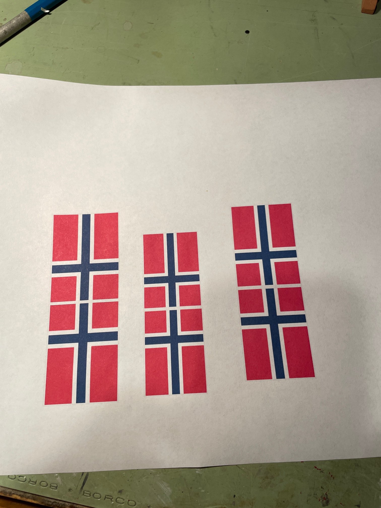
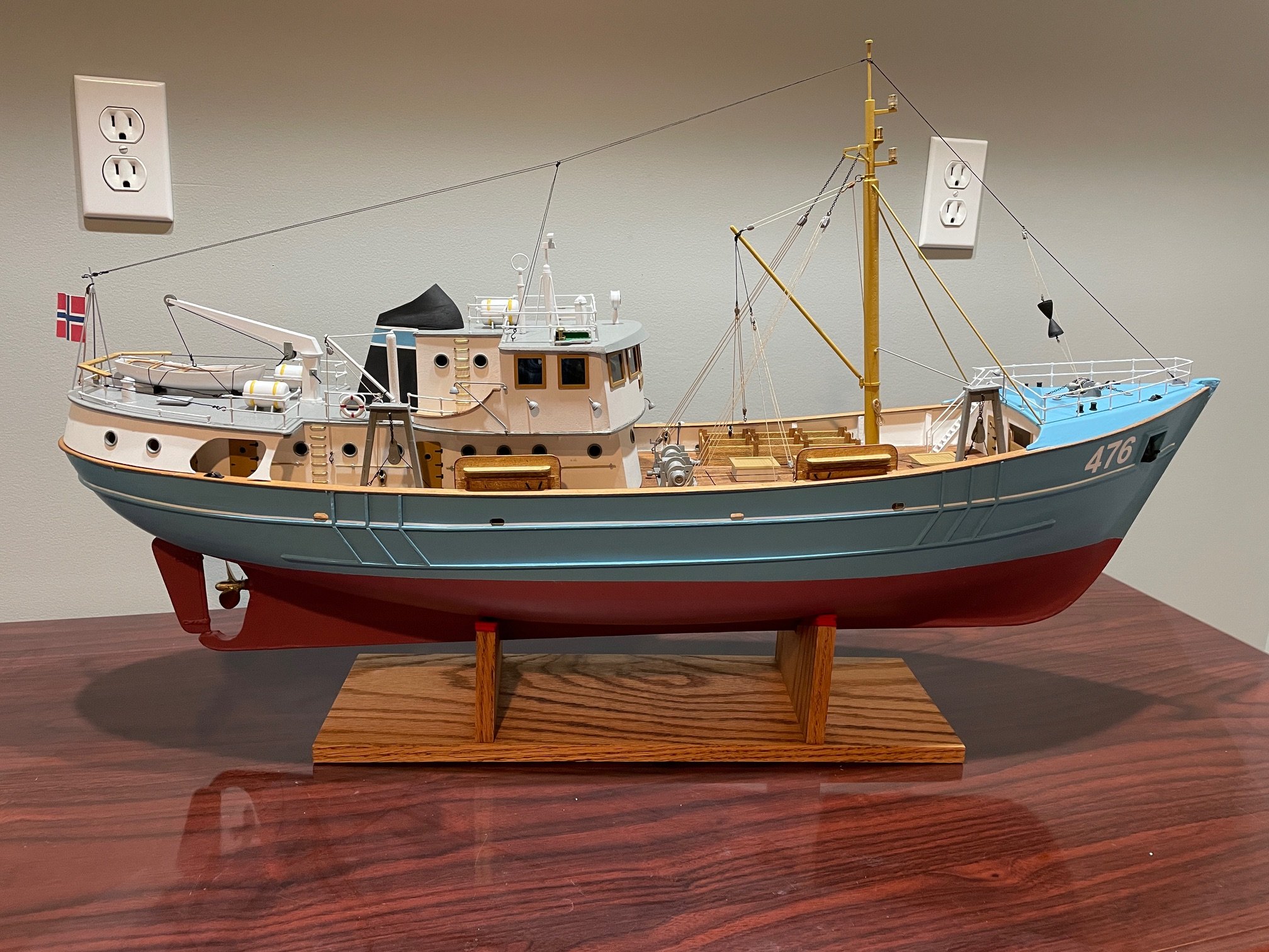
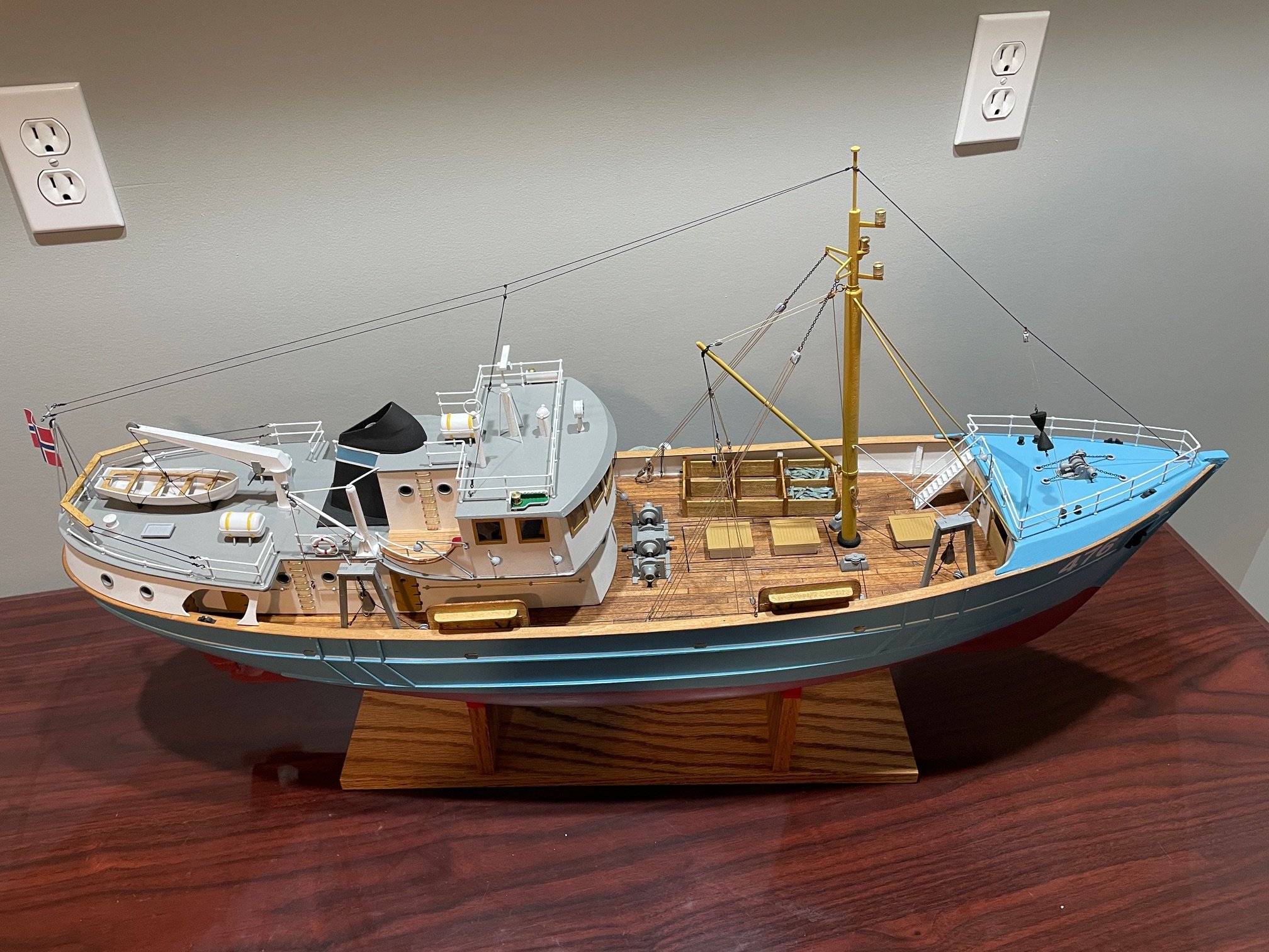
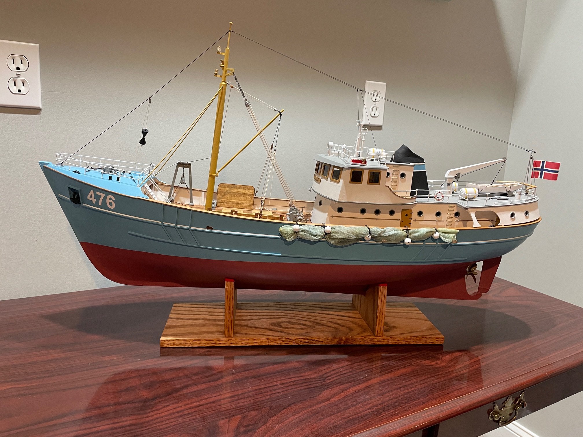
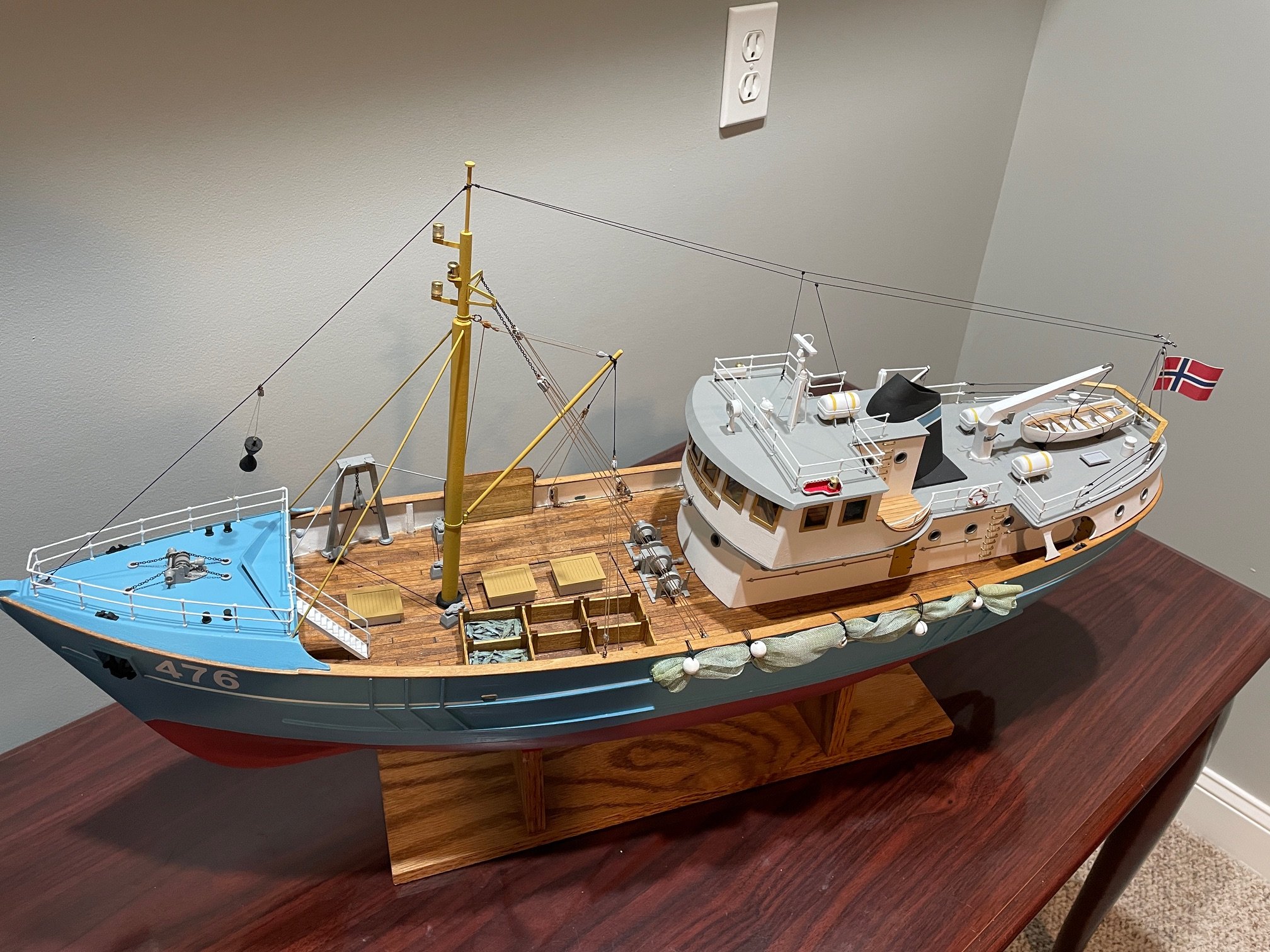
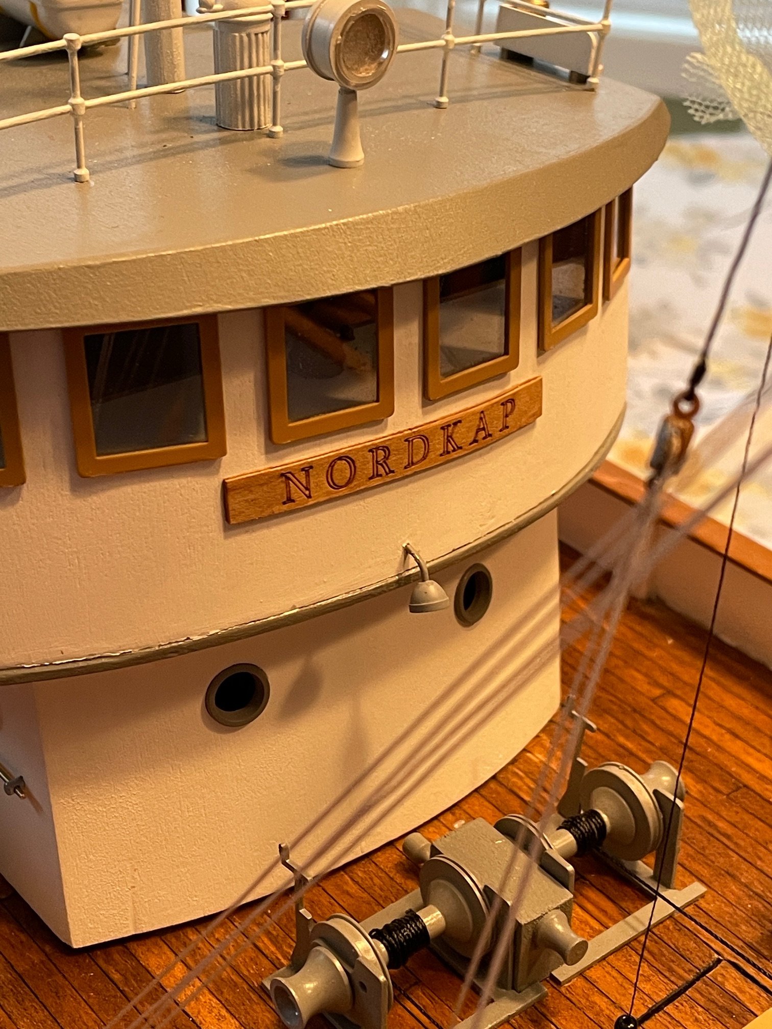
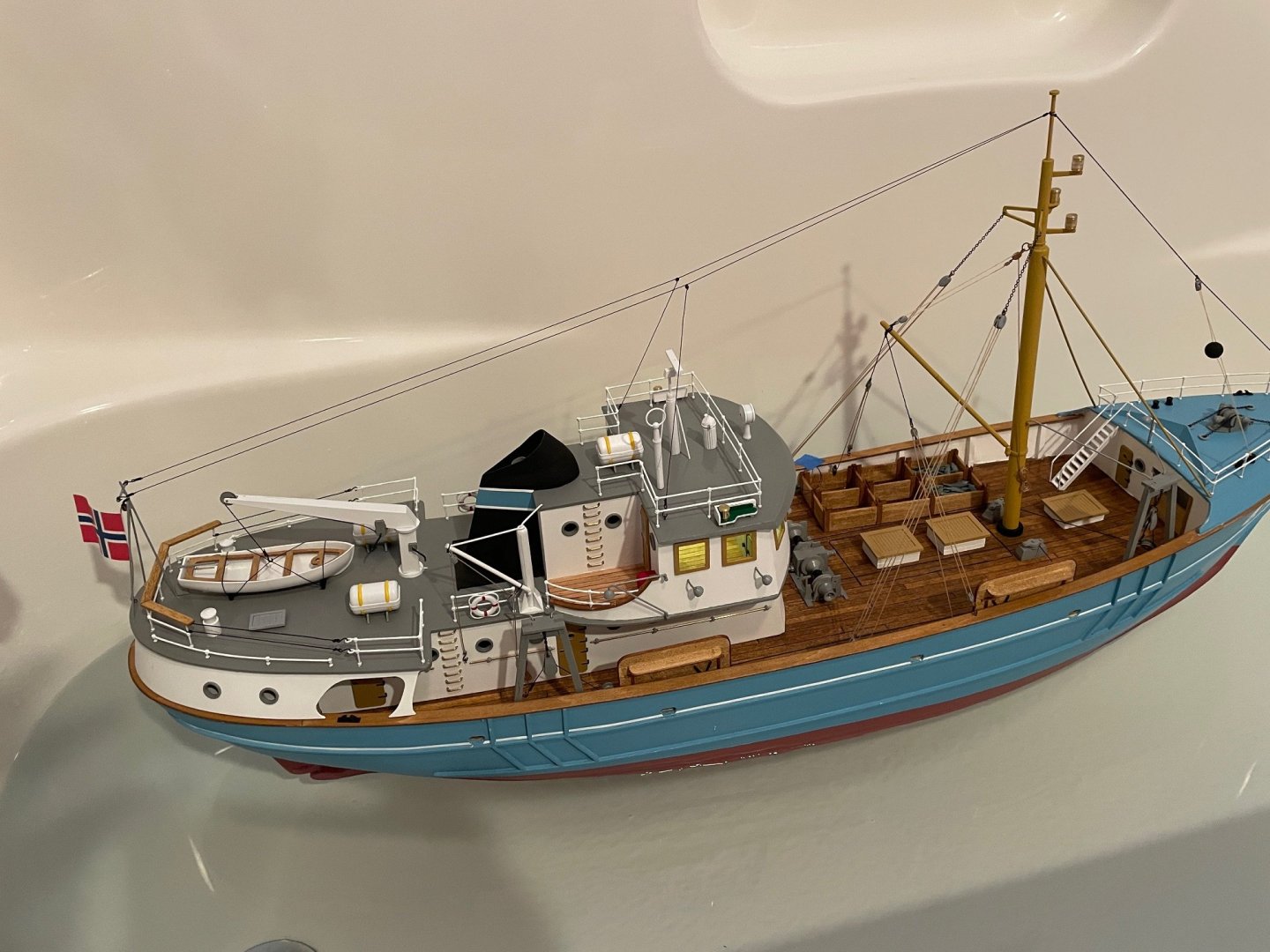
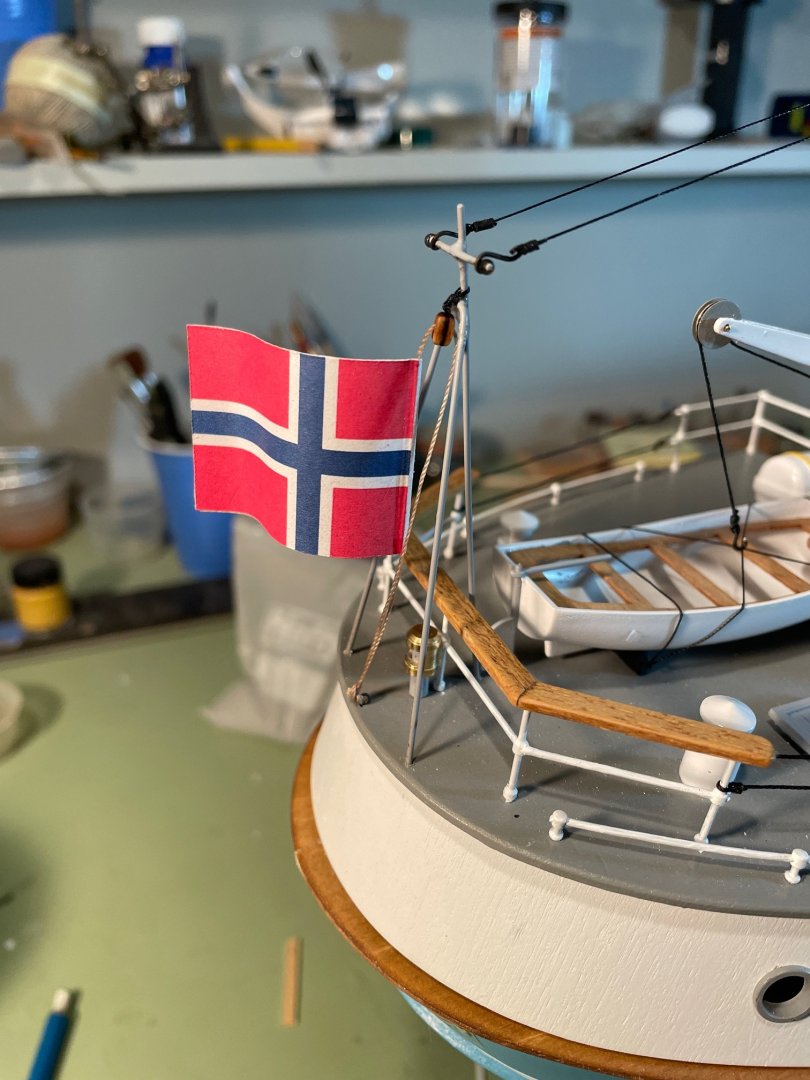
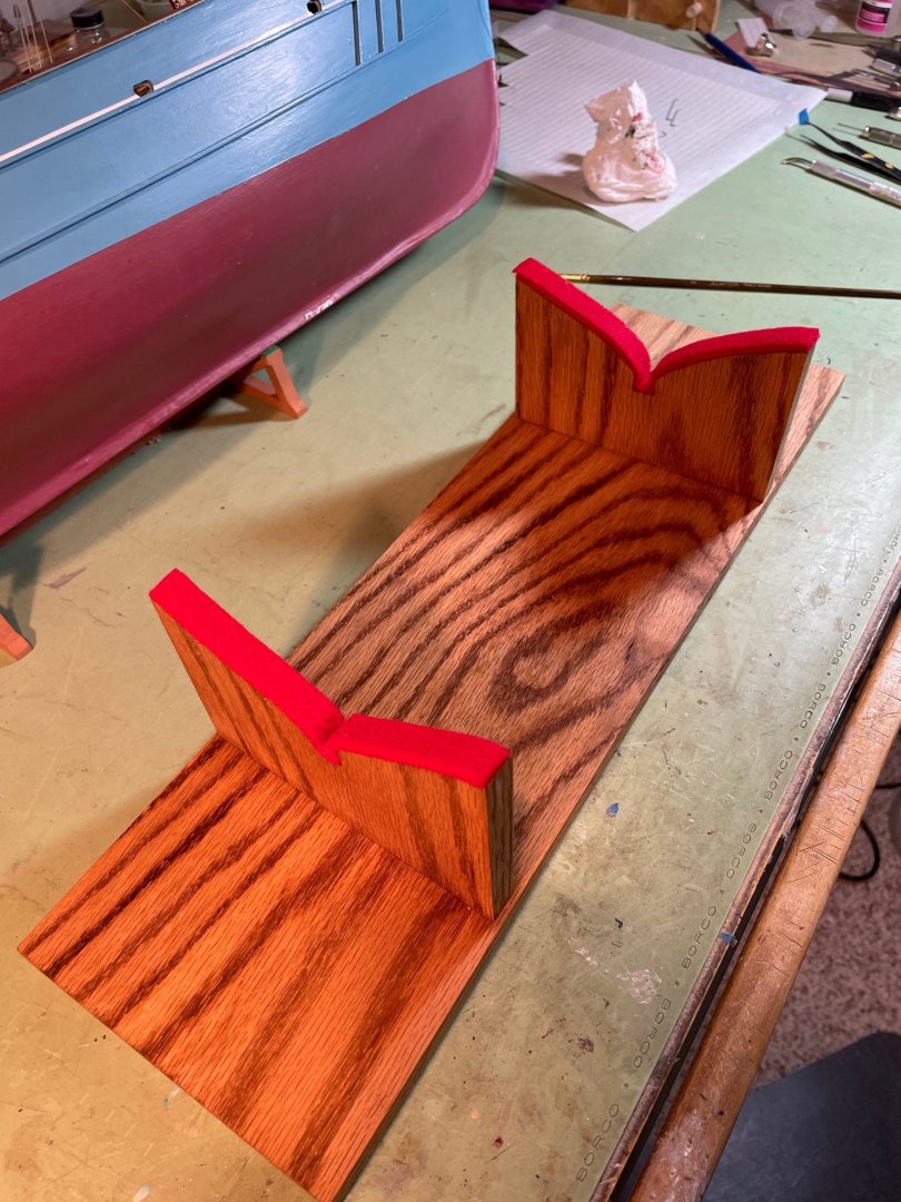
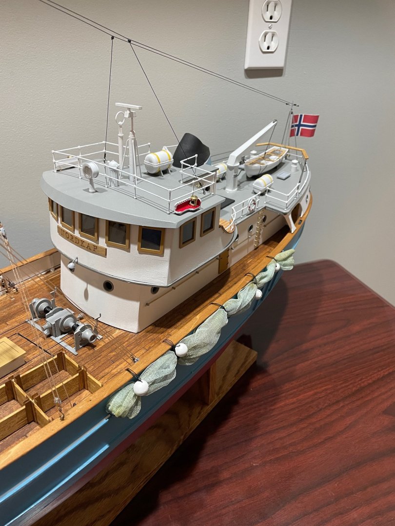
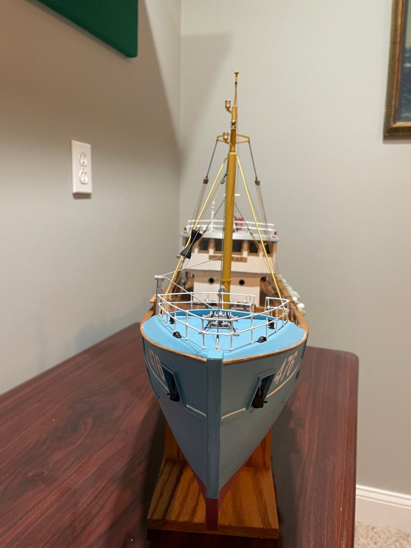
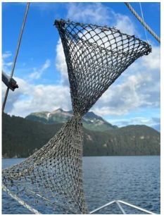
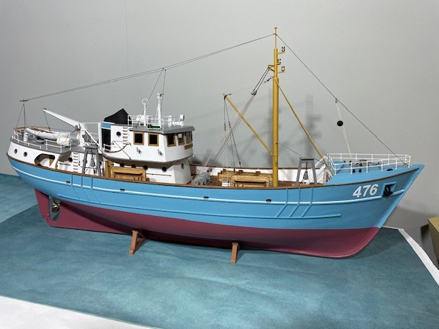
As I was wrapping things up, I realized I still needed two things: a flag and a much sturdier base. For the flag, I did some digging to see if there was a real trawler named Nordkap. With a little help from AI, I figured out it’s actually a generic model of a North Sea trawler rather than one specific ship. Since the name "Nordkap" is Norwegian, I decided a Norwegian flag was the way to go. I printed out a few different sizes to see which looked right and ended up picking the mid-sized one. The original base felt a little flimsy to me, so I built a new, beefier one. It feels a lot more solid now, which will definitely come in handy when I’m setting the boat down outside while taking her out for a sail. With that I believe I'm finished with the build, the only thing left is sea trials. Completed model I’m not sure if this is the proper place for the trawl net, but I wanted to position it where it wouldn’t interfere with removing the cabin or accessing the battery hatch. And I only had a few parts left over. I have no clue what these are for or where they go. I’d like to thank everyone for the kind words of encouragement throughout my build, as well as for all the likes and support. Along the way, I learned a great deal—including new skills related to remote control components and seamanship. While the building phase is now complete, there’s still work ahead to prepare the ship for sailing.


- 79 replies
-
- 13
-
-
-
- Nordkap
- Billing Boats
- (and 2 more)
-
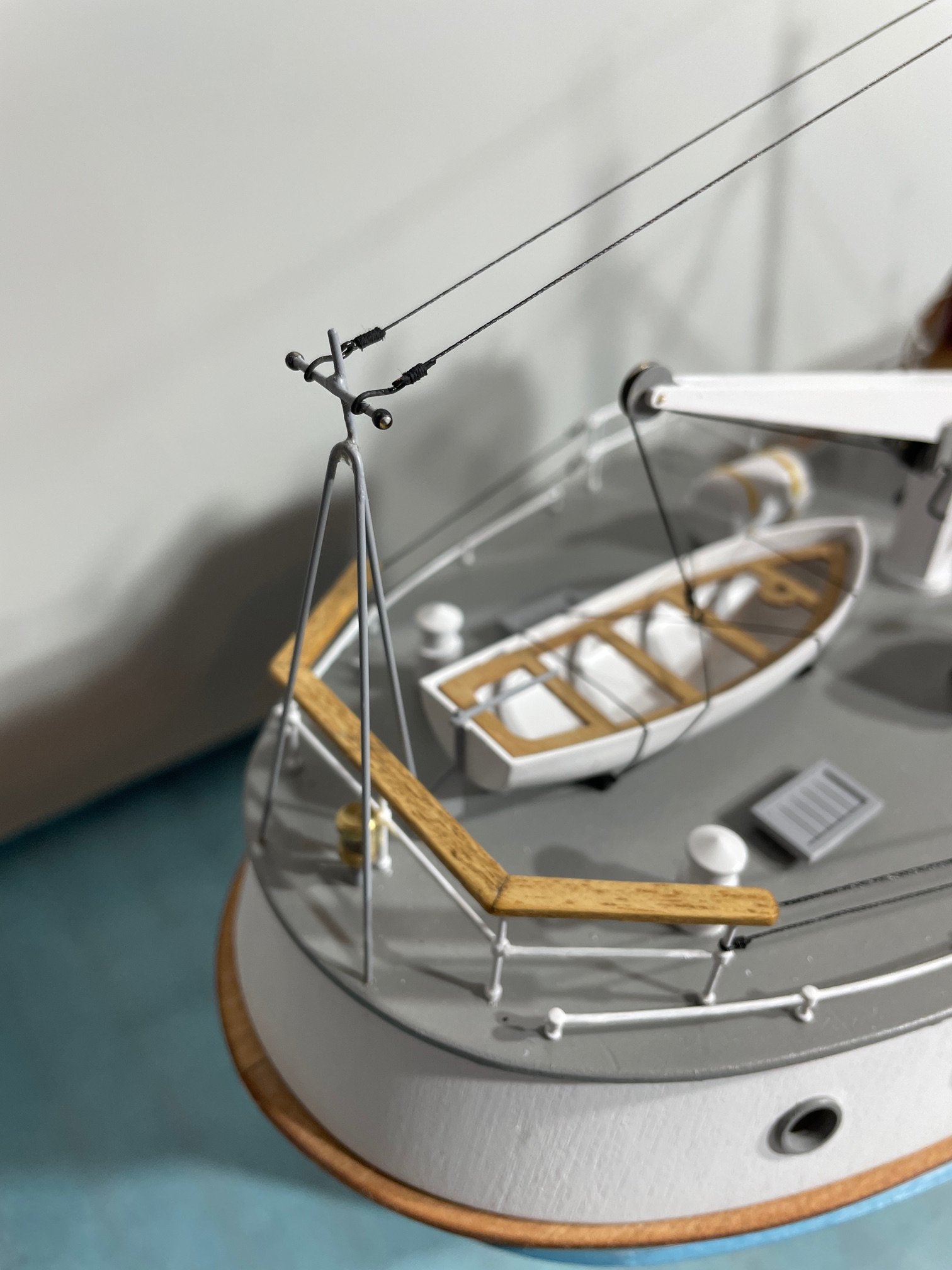
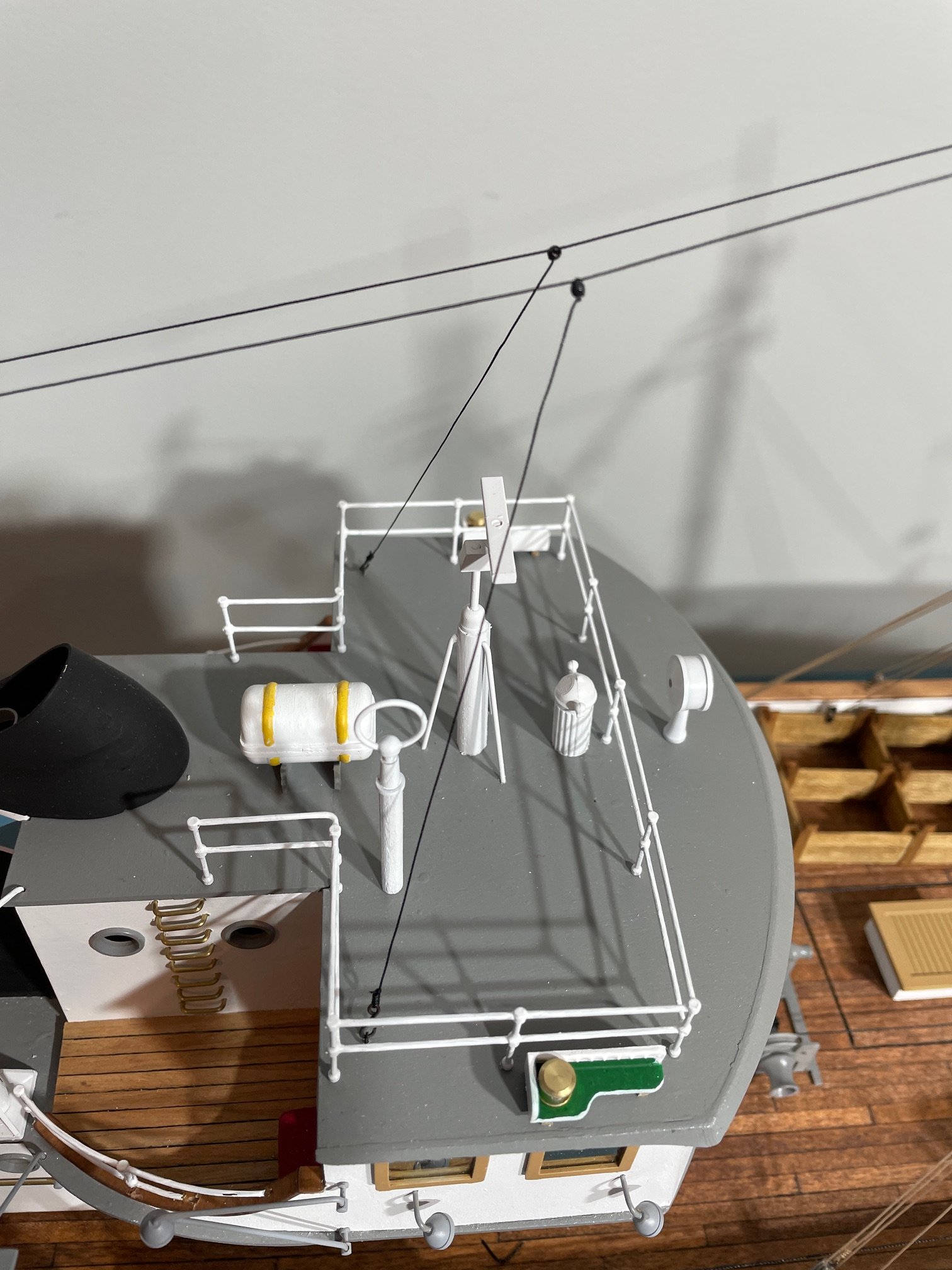
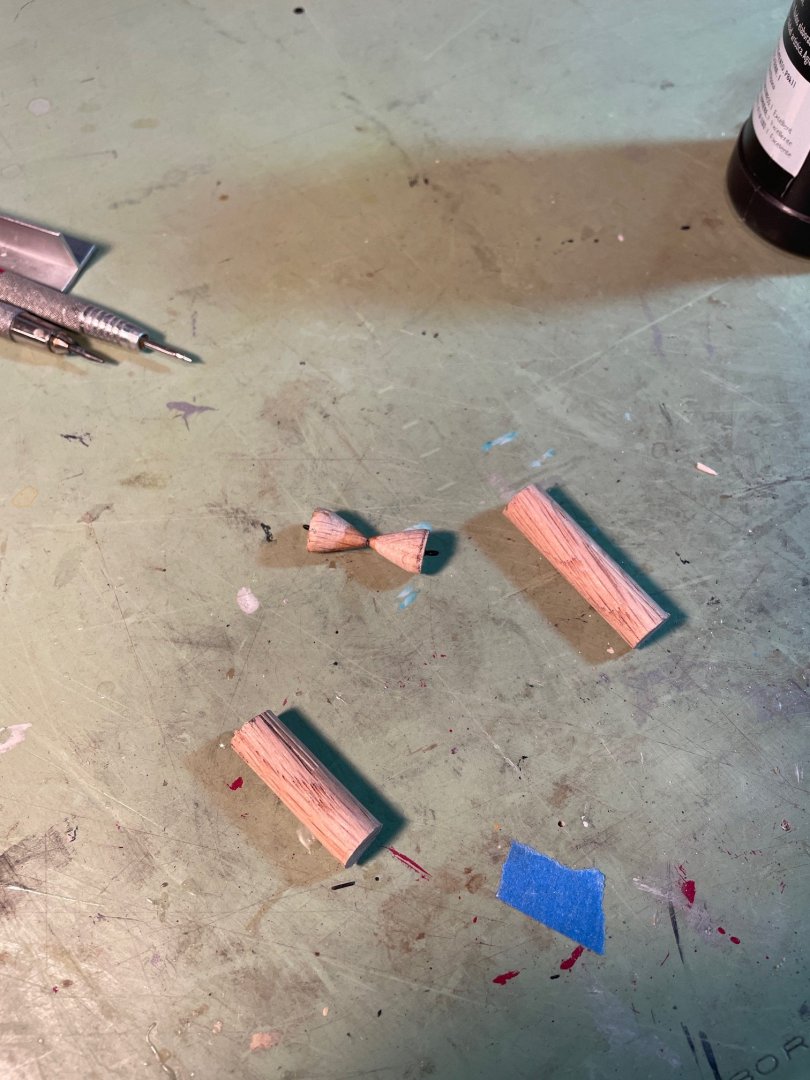
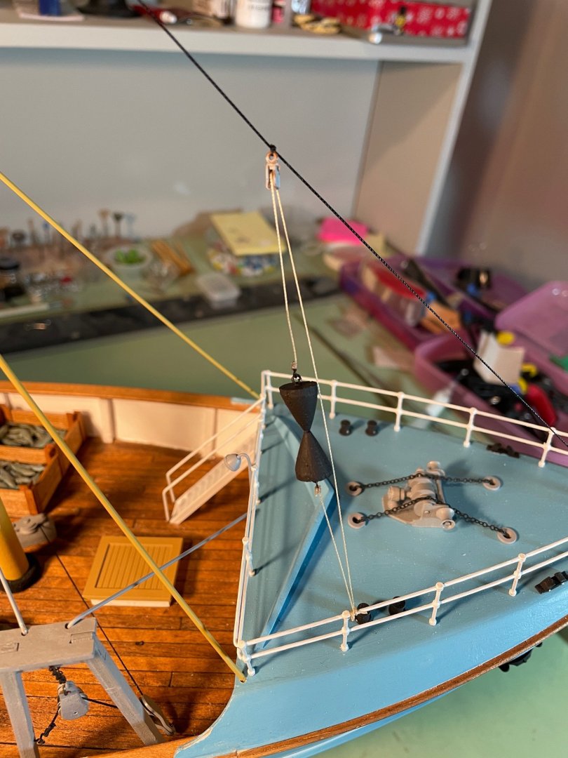
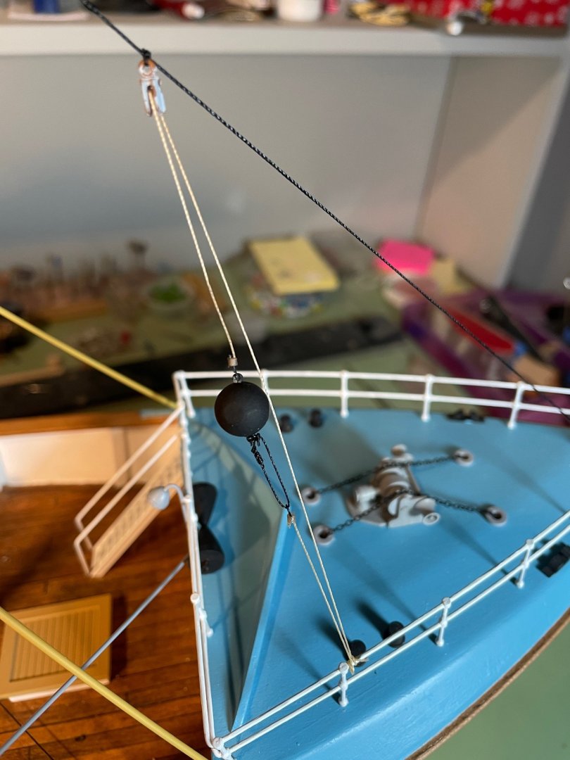
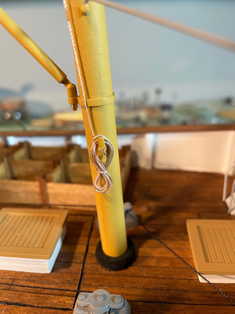
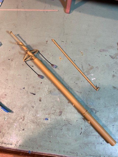
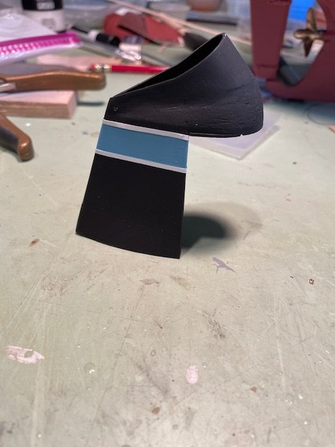
Based on @Kenchington's suggestion, I decided to create a new day shape for when the ship is underway. Using a wooden dowel, I sanded down the end to form two cone-shaped pieces. These pieces were glued together, and eyelets were added to each end to make it easier to connect the halyard. The entire shape was then painted black. I tied two small hooks to the ends of the halyard, allowing for quick and simple shape swaps. I kept the original round day shape and made a few modifications so it could be easily reattached to the halyard when the ship is sitting on the shelf. I'm always impressed as to how much knowledge is shared on this forum. As more of a modeler than a sailor, I'm always grateful when people take the time to share their expertise with those of us who aren’t as well-versed in seamanship as others. Thank you all for all the likes and have a Happy New Year.
- 79 replies
-
- 7
-
-
- Nordkap
- Billing Boats
- (and 2 more)
-
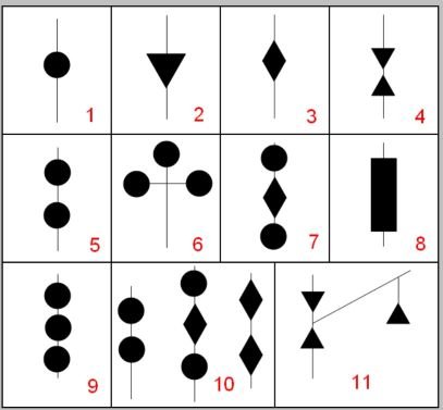
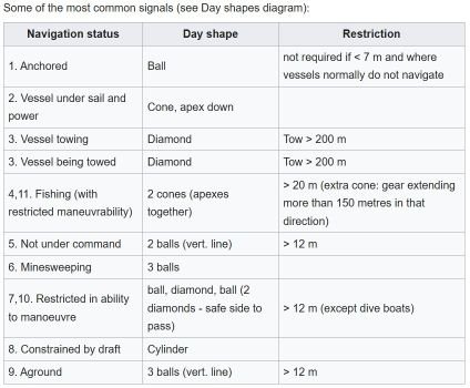
@Kenchington, thank you for the information and the nice words. I did some additional research on the topic of day shapes for ships and found the following. I’ll see if I can come up with a fishing day shape.
- 79 replies
-
- 1
-
-
- Nordkap
- Billing Boats
- (and 2 more)
-
@Ian_Grant, thank you for the kind words
-
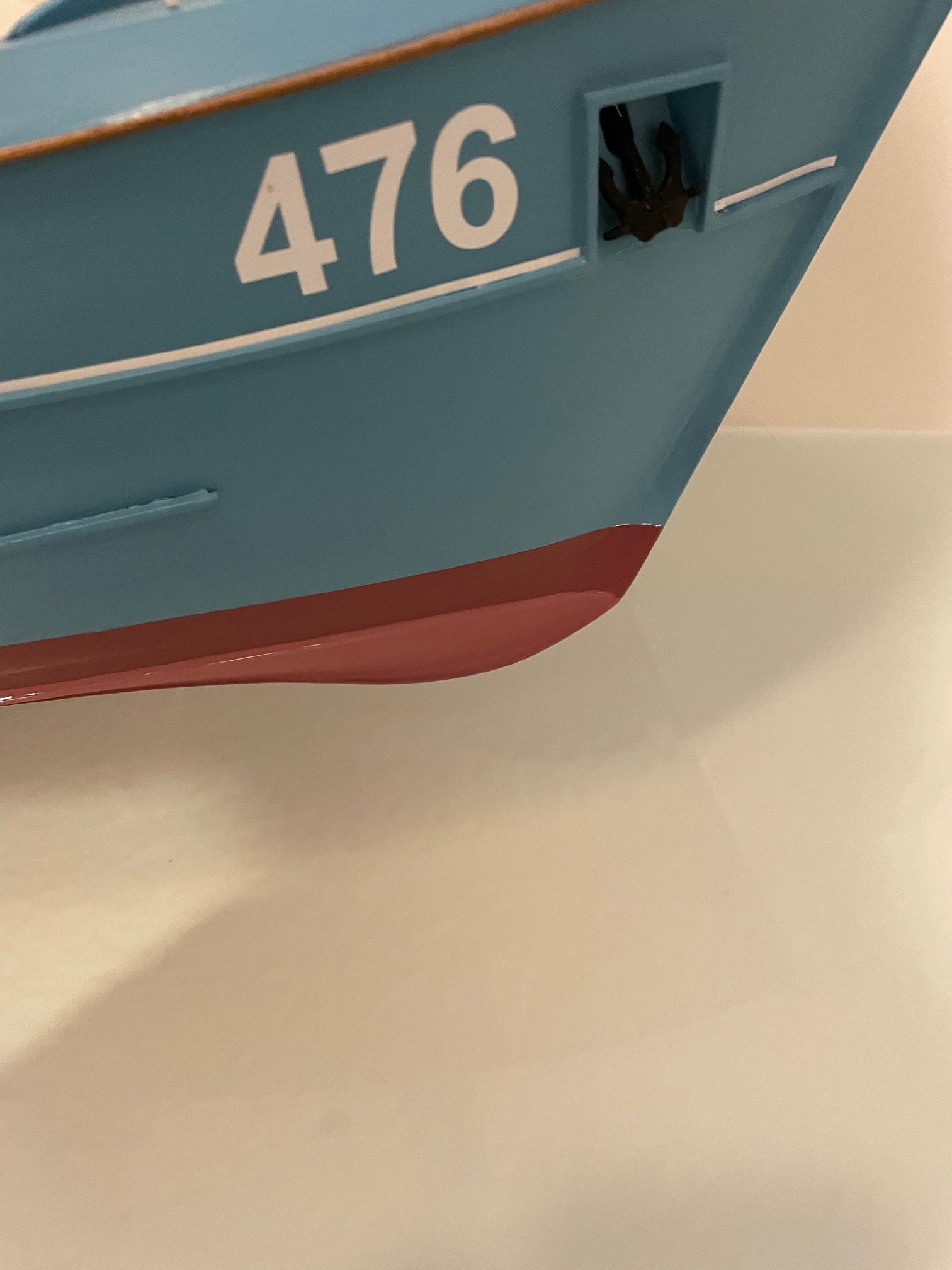
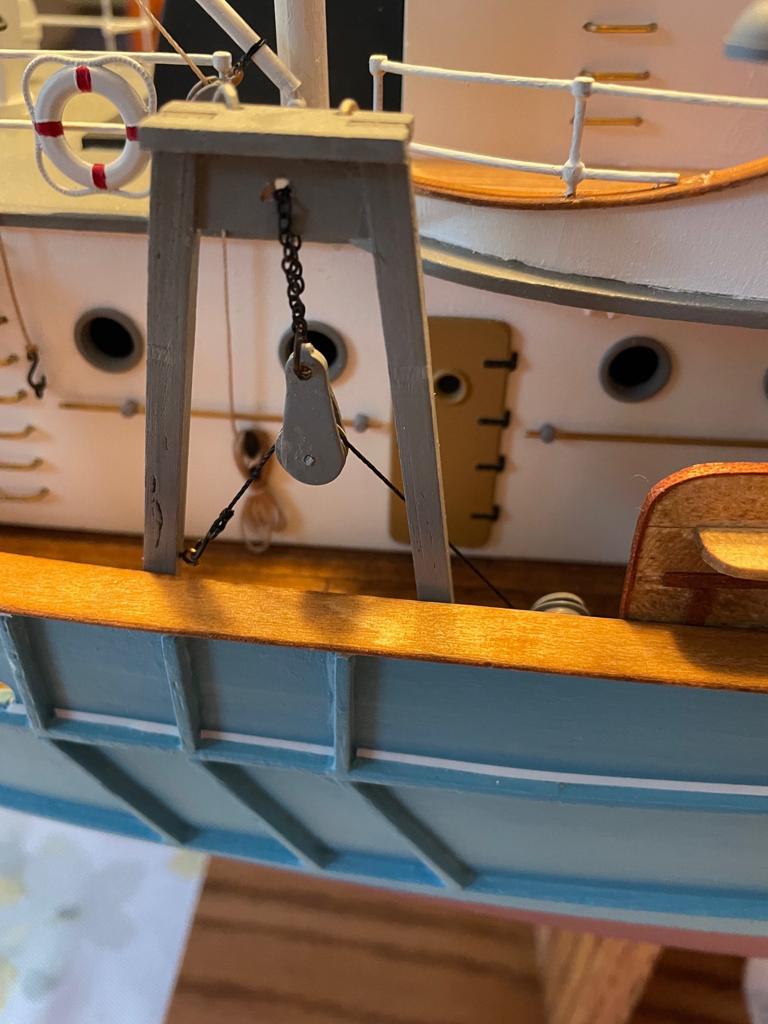
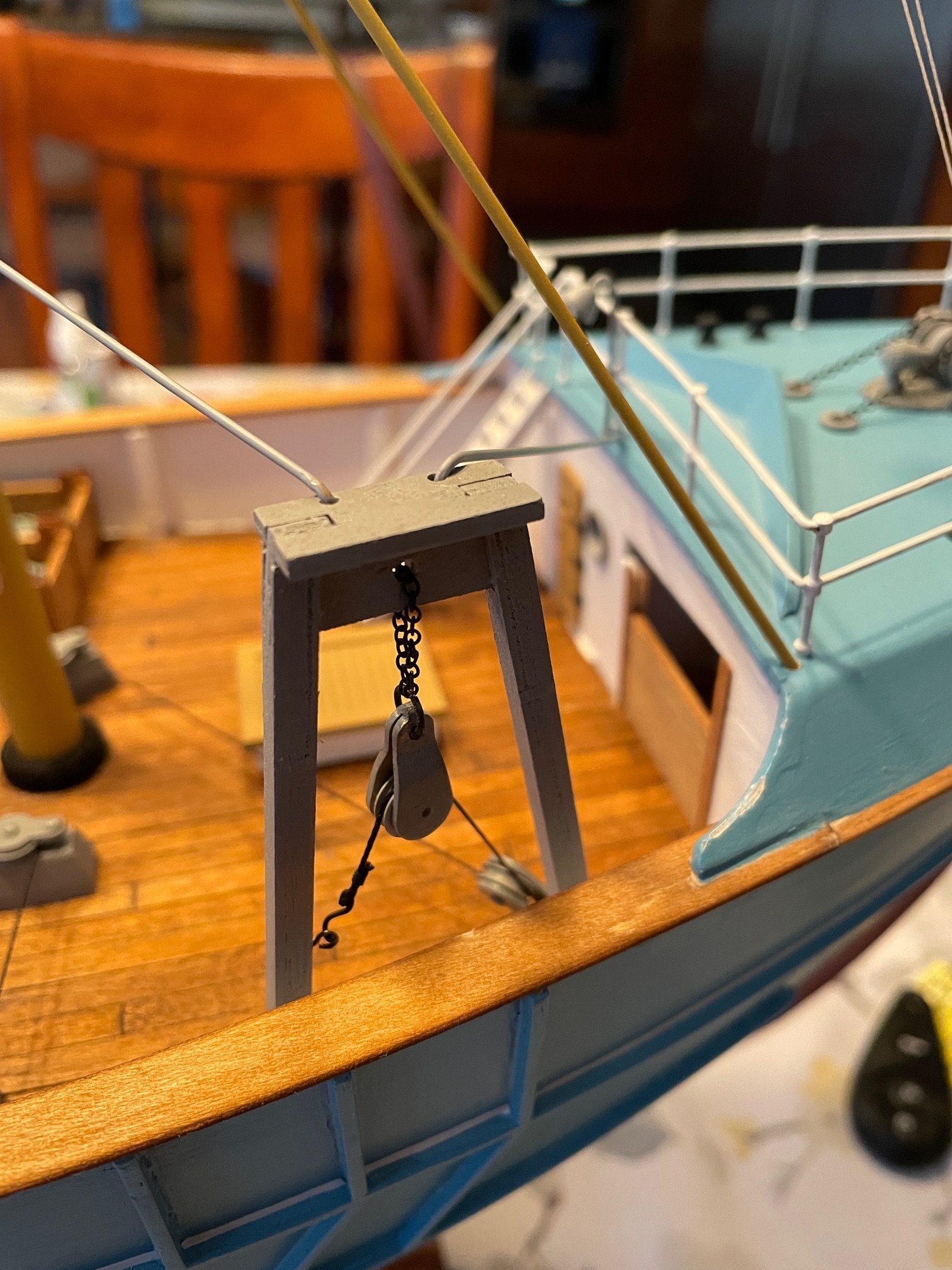
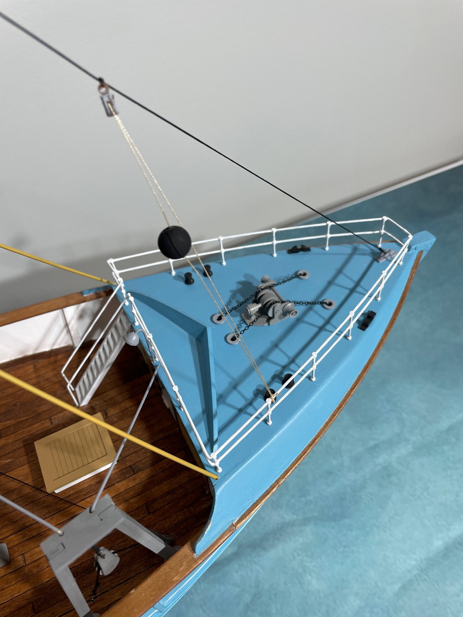
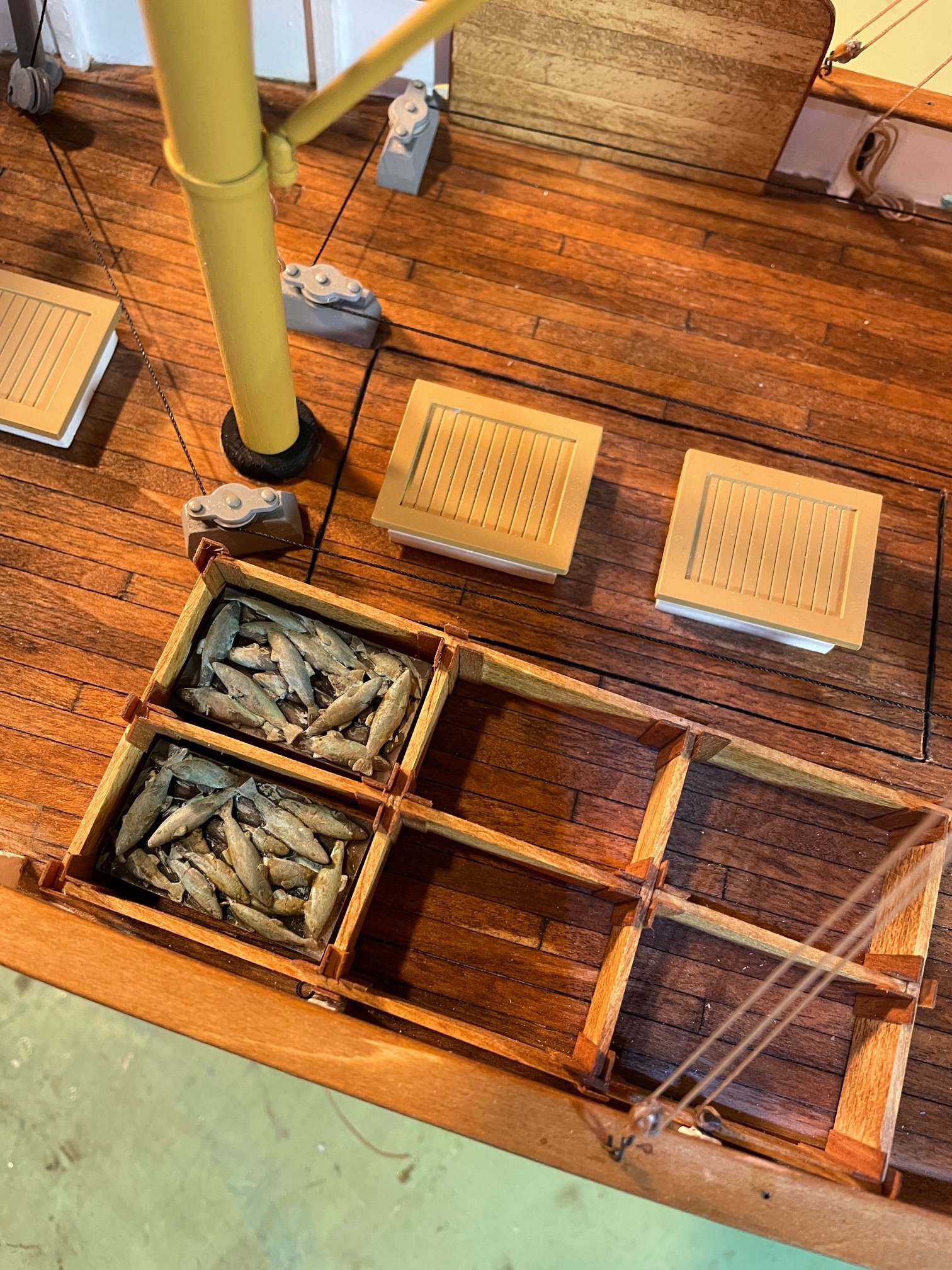
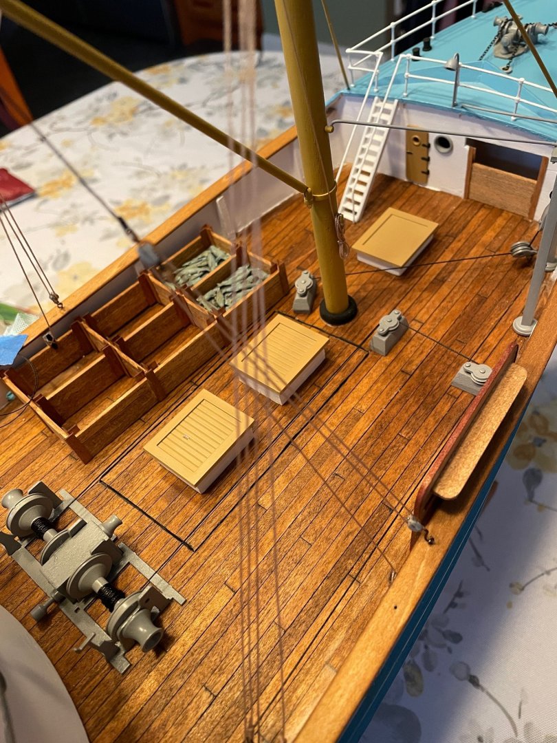
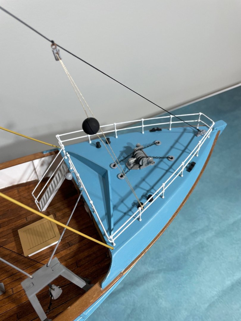
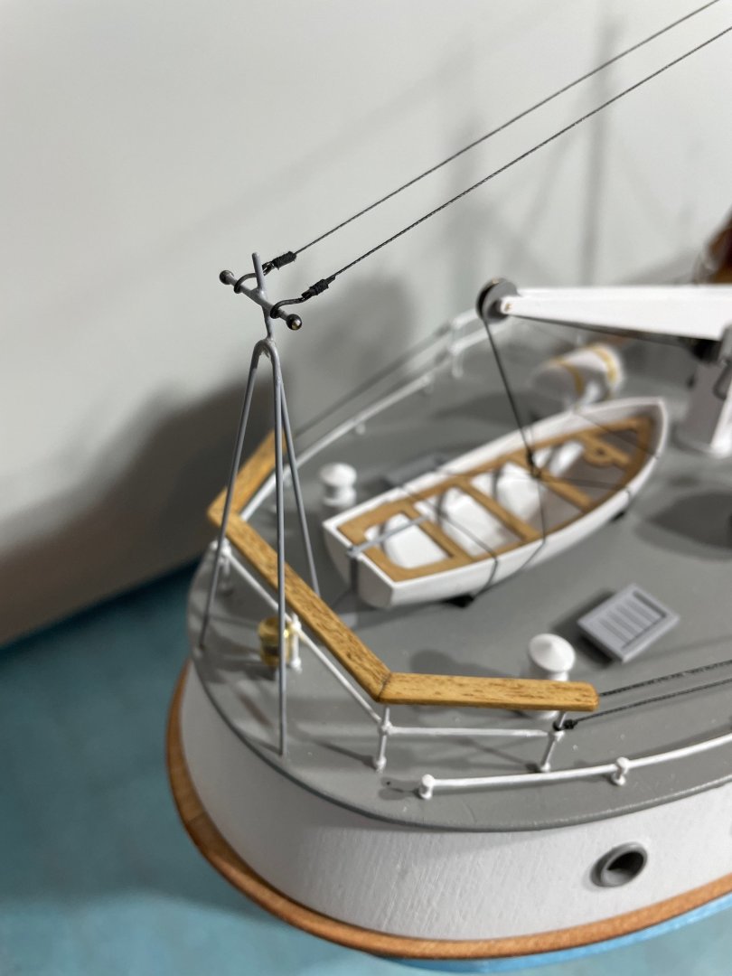
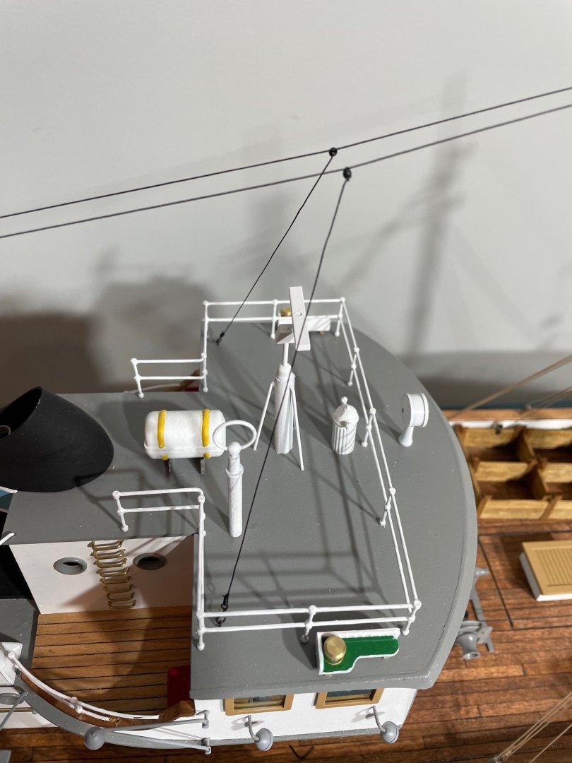
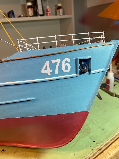
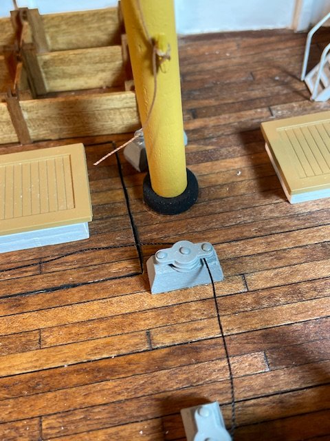
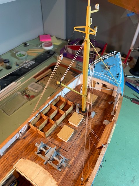
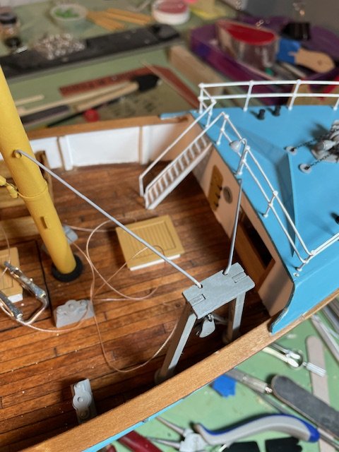
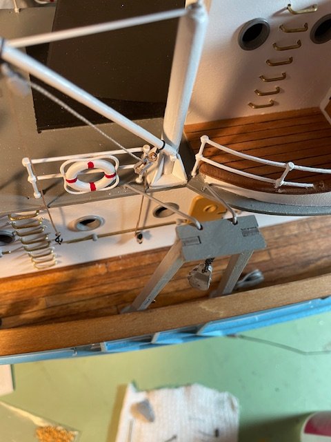
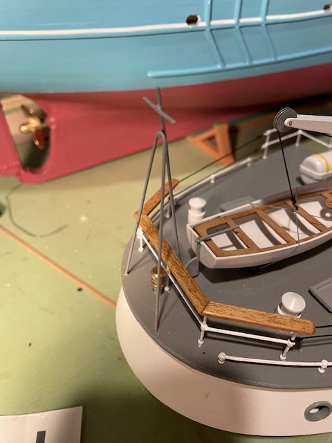
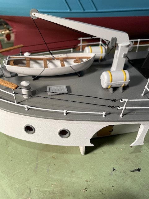
Getting close to the end The cables running from the deck cranes to the windlass were run along the deck and through the deck pulleys. Next I installed what might be a forestay running from the masthead down to a gusset plate at the bow. From this stay, a halyard was rigged down to a handrail post located on the bow deck. On this halyard I installed a wooden ball that was shown on the plans, though initially I had no idea what it’s called or its purpose. After showing a photo of it to my brother-in-law— an experienced sailor—I learned it’s an anchor signal ball. Further research confirmed that an anchor ball (or "day shape") is a black spherical marker used by vessels to indicate they are at anchor during daylight hours. Learned something new! Next, what I assume are antenna wires were installed running from the masthead aft to the wire support tower at the stern. These wires need to be easily removable so the cabin could be lifted off the model. To achieve this, I incorporated small hooks at the ends of the lines that attach to the wire support tower at the stern, allowing for simple detachment and reattachment. I also attached small hooks to the wires that run from the antenna wires down to the cabin roof deck for easy removal and reattachment. The ship’s number decals were added, The plastic fish were painted and placed into the fish storage bins. (they don't look to fresh 🫢) I also added several rope coils Nameplate installed Overall to date. Thanks for looking in and for the likes


- 79 replies
-
- 8
-
-
-
- Nordkap
- Billing Boats
- (and 2 more)
-
@mandolinut Just discovered your build and spent some time going through everything. You're doing an amazing job, and I really love all the extra details you're adding. I'm also a former diver, and I was influenced by Jacques Cousteau and, of course, Lloyd Bridges in Sea Hunt. Keep up the great work!
-
lets try. @palmerit, well that was easy. @palmerit thank you
-
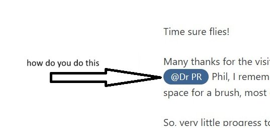
Please forgive me if this is covered somewhere in this forum. I’ve looked through a number of posts but couldn’t find anything that answers this. I’m sure this is obvious to those who are more text-savvy, but could someone tell me how to create those blue shaded name tags? (See picture below.) Thank you.
-
Maybe I’ll just keep her on the shelf and watch the propeller go around 😄😉. Kidding, of course. Damn the torpedoes—full speed ahead.
- 79 replies
-
- 2
-

-
-
- Nordkap
- Billing Boats
- (and 2 more)
-
Hi Craig, Thank you for your input. I believe I performed that calibration when I first installed all the electronics. The propeller RPM does vary with throttle position, so I think it’s working correctly. In the tub, since I’m not yet used to the controls, I pushed the throttle a little too far forward and didn’t have much room to work with. I think once I get it into a larger body of water, I’ll be able to get used to them more easily.
-
Ship is looking great Knocklouder. I like the name decals and was wondering how you made them.
- 73 replies
-
- 4
-
-
- Steam Cutter
- Harriet Lane
- (and 2 more)
-
Thanks, Alan. I forgot to mention in my post that I didn’t use the white rigging thread provided with the kit. Instead, I substituted some rigging I had left over from a previous model—black for the standing rigging and tan for the running rigging. Thanks for the kind words, Ian. There is an edge plank (coaming) around the perimeter of the opening where the cabin is located. It’s not very high (about 1/8"). I could probably add an extension to make it a little higher if you think it should be. You made me think however about the battery hatch I cut into the main deck. I'll need to come up with something to waterproof it. LOL—of course I had to try it out in the tub, and to my surprise the boat is a little faster than I anticipated. Good thing the tub has rounded edges, no damage to boat or tub. I did get it to move forward and reverse, and still no leaks.

- 79 replies
-
- 4
-
-
- Nordkap
- Billing Boats
- (and 2 more)
-
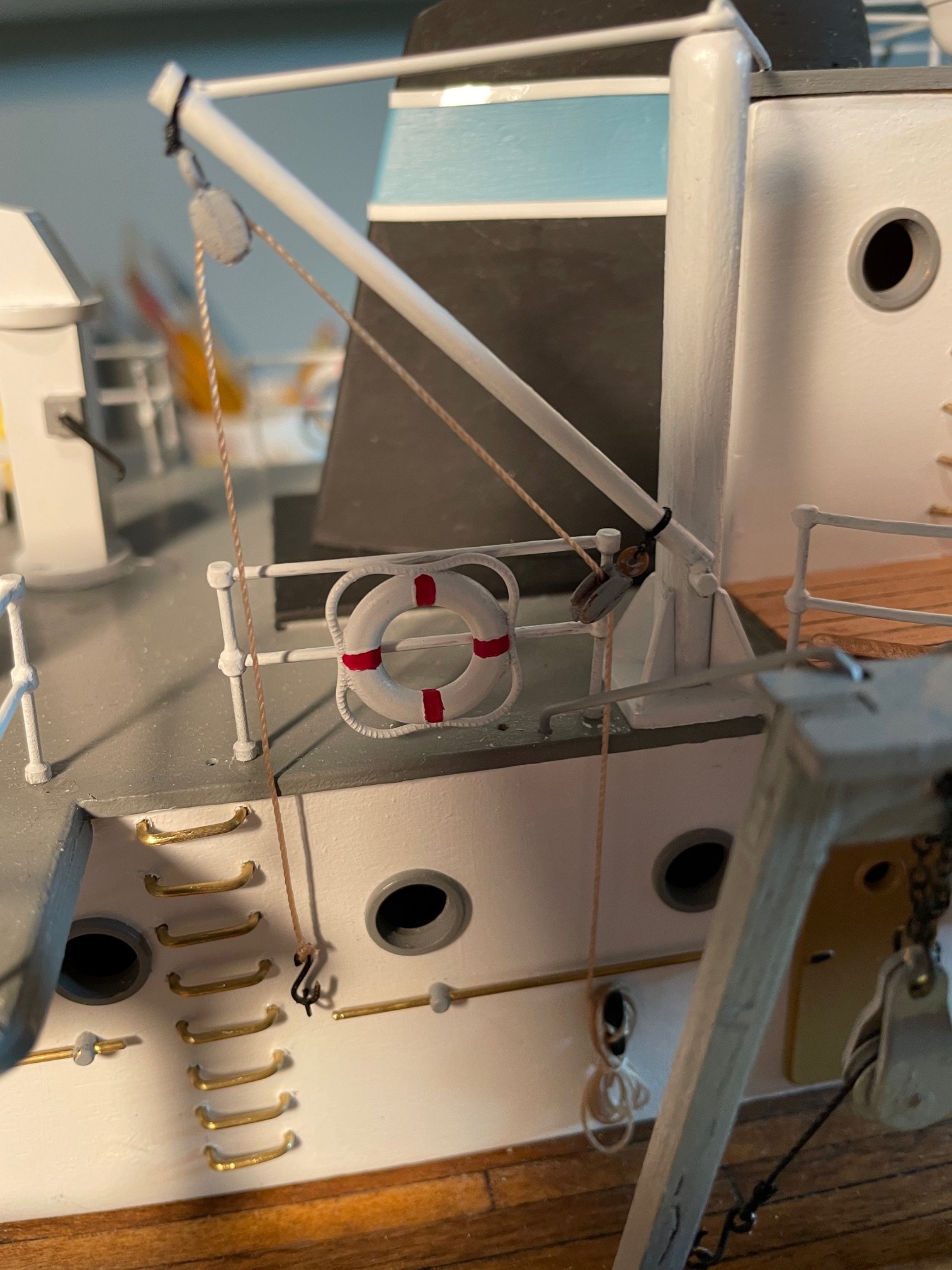
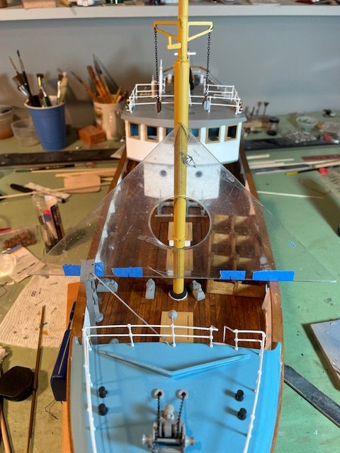
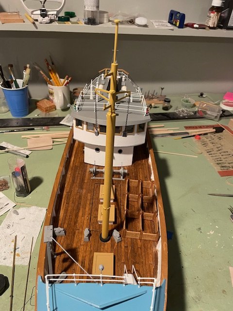
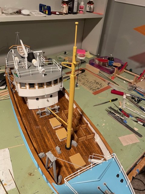
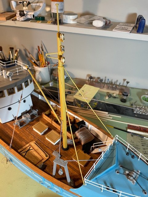
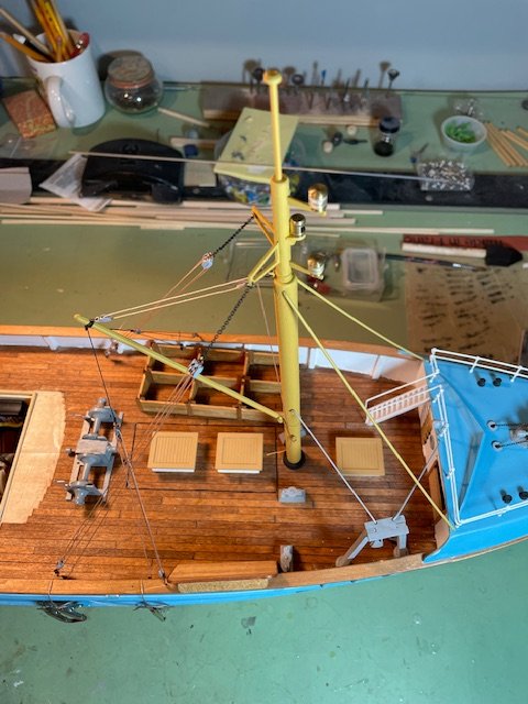
Stepping the Mast: The mast and boom were pre-assembled with all their attachments and painted before being installed on the ship. My standard method for stepping the mast involves using a 45-degree right triangle. I use the triangle to help ensure the mast is plumb athwartships. First, I scribe a line in the plastic triangle, bisecting the 90-degree angle and making it perpendicular to the hypotenuse. Then, I measure the overall distance athwartships from the outboard edges of each cap rail, where the triangle will be placed. Dividing this distance in half, I mark the same measurement on either side of the scribed line along the hypotenuse of the triangle. Next, I position the triangle upright against the mast, ensuring that the two marks line up with the edges of the cap rail. With the apex of the bisected 90-degree angle centered on the ship, it will be perfectly perpendicular to the deck. The position of the mast fore and aft sometimes needs to be braced into position, this mast I did not have to do that. I use white glue for this step, as it allows me time to adjust the mast into its final position. The main advantage of this method is that it doesn't require the ship to be perfectly leveled. As long as the ship has a reasonable degree of symmetry, and the triangle is correctly positioned across the cap rails, the apex of the triangle will always be centered on the ship and 90 degrees to the deck. While I’m not certain whether these types of masts would traditionally have a mast coat, I did apply one to provide additional support for the mast. Mast and Boom Installation: With the mast and boom in place, I moved on to rigging the block and tackles. This part was fairly straightforward, though I did make one mistake: I should have waited to glue the fish storage bin in place until after completing the rigging. First, the wire bracing for both the mast and the forward deck crane were then installed. Next, the rigging for the boom Then the mast rigging Additionally, I added the wire bracing for the aft deck crane. Since this bracing runs from the crane to the superstructure (which must be removed in order to install the battery and turn the motor on), I didn’t glue this bracing in place. This will allow me to remove it easily when needed. Getting close to the end now, just a few more odds and ends to complete. Then I think another water test is called for. Thanks for looking and for the likes.
- 79 replies
-
- 6
-
-
-
- Nordkap
- Billing Boats
- (and 2 more)
-
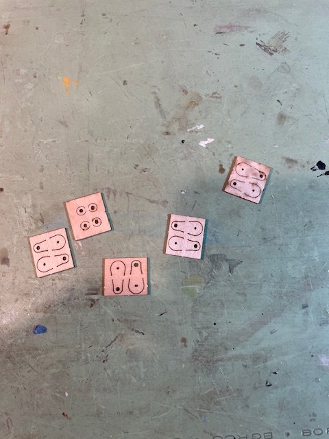
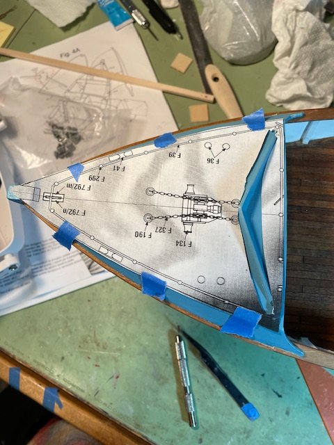
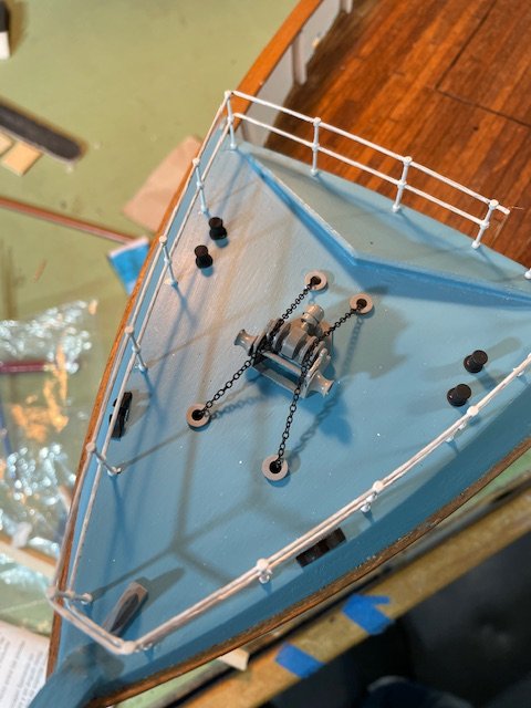
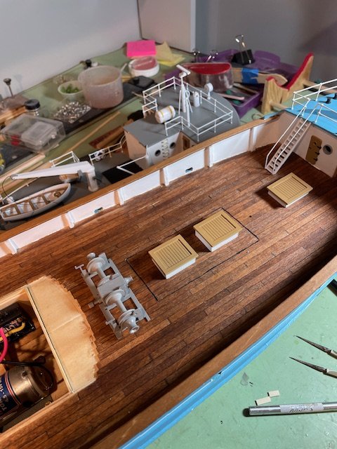
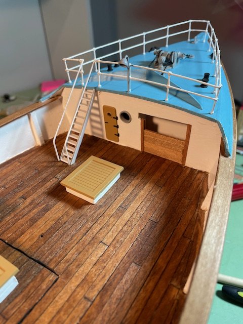
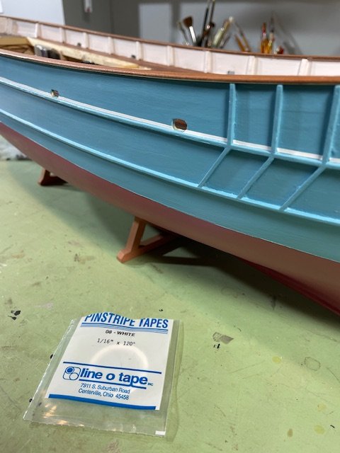
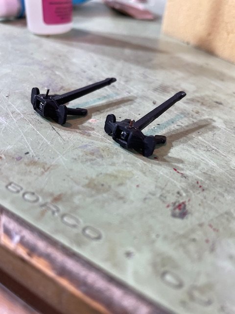
I was a little slow posting this update because I’m just getting over my first case of COVID. It took five years to finally catch it, and when I did, it did a pretty good job on me—but I’m all better now. I started at the bow, installing the handrail and windlass. To accurately locate the handrail posts, I made a photocopy of the bow section from the plans and taped it in place as a guide. I used a compass point to mark all the locations. I also marked the bollard locations on the deck. Next, I installed the ladder, deck hatches, and the larger windlass on the main deck. The two higher hatches are mounted on the removable deck portion to access the battery. After that, I jumped over to the hull pin striping. I had some 1/16” white pinstripe tape left over from another project, and it worked out very nicely. Then it was back to the superstructure. I installed the rear antenna support and the cable handrail, finished painting the stack and the anchors, and added pins to the anchors to help secure them to the hull. Thanks for looking in and for the likes.
- 79 replies
-
- 5
-
-
-
- Nordkap
- Billing Boats
- (and 2 more)
-
Going to grab some popcorn, sit back and follow along. Good luck on the build Bob.
- 73 replies
-
- 5
-
-
-
- Steam Cutter
- Harriet Lane
- (and 2 more)
-
Thanks Alan, I appreciate the nice comments and thanks for looking at my build.