_SalD_
-
Posts
854 -
Joined
-
Last visited
Content Type
Profiles
Forums
Gallery
Events
Everything posted by _SalD_
-
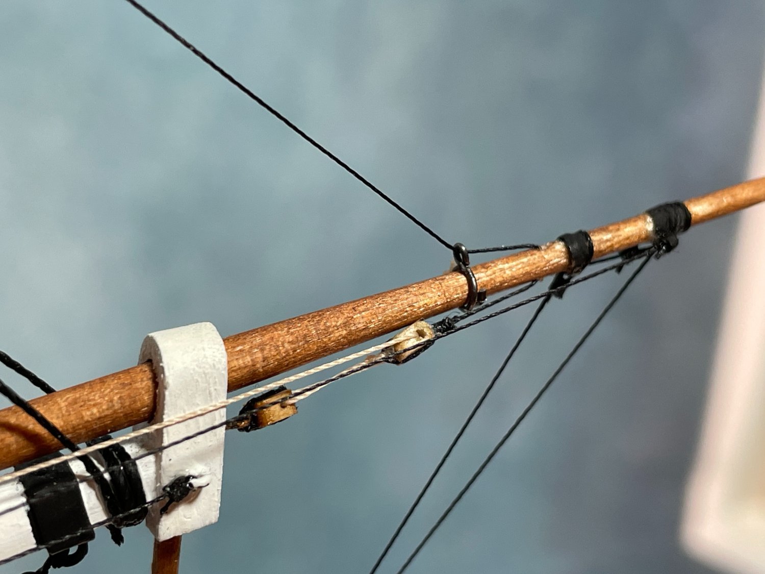
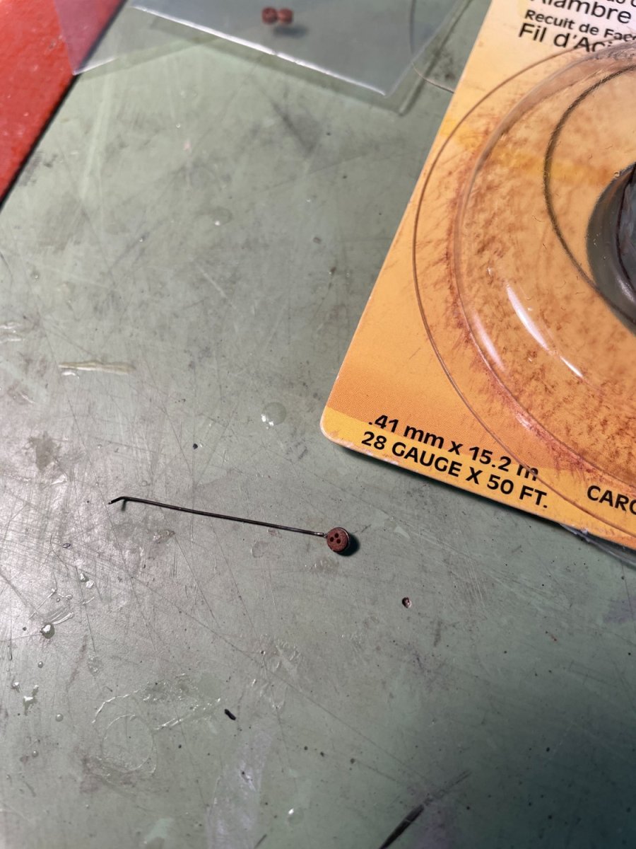
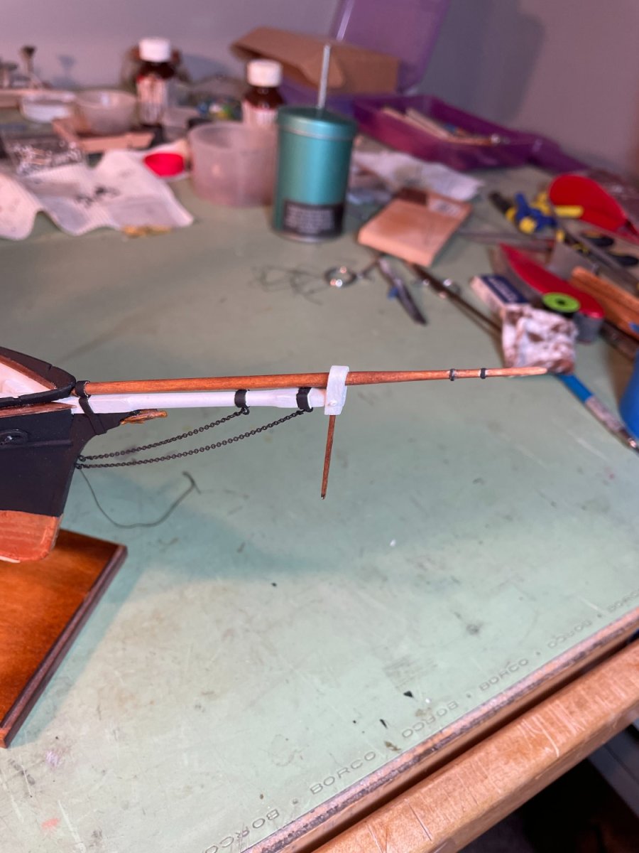
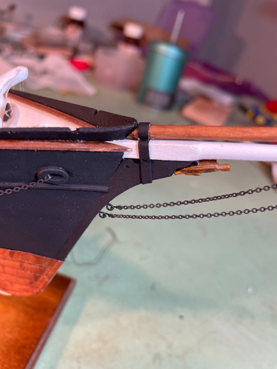
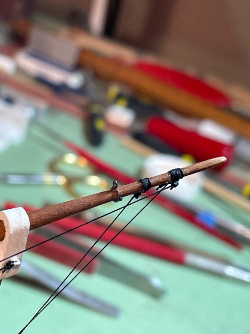
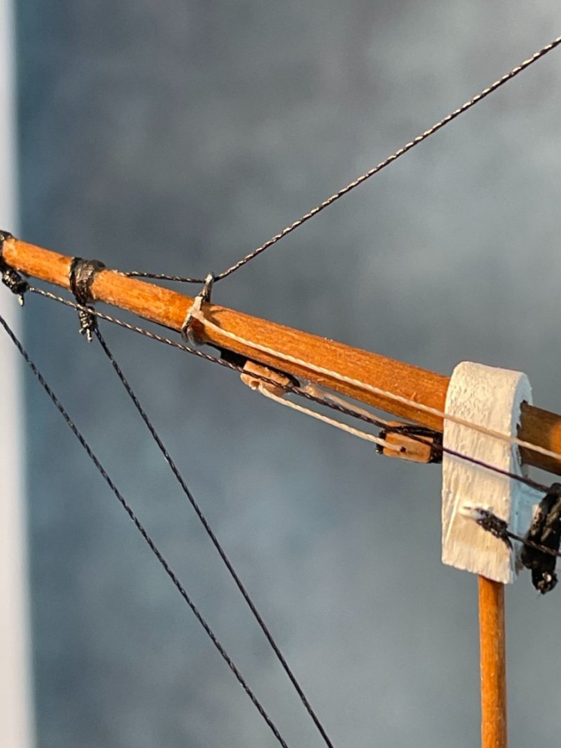
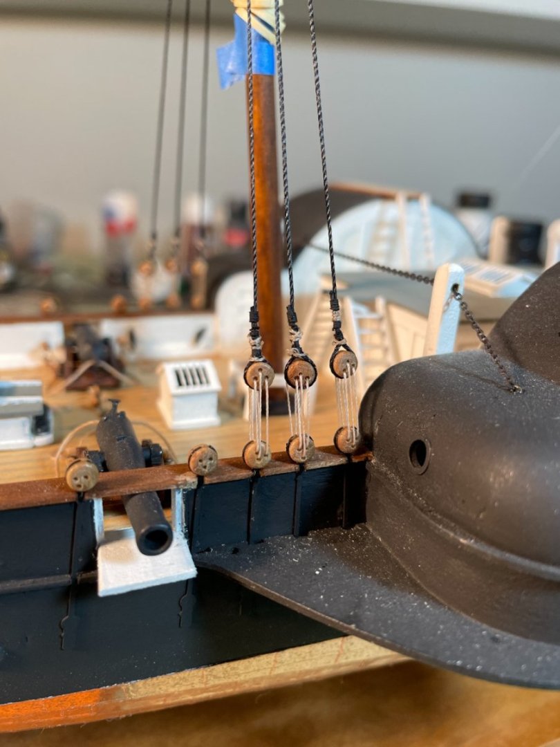
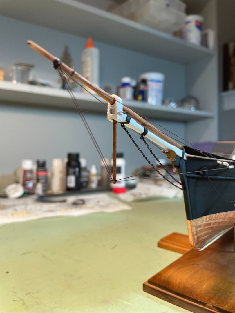
 Jib Stay: For the jib stay I decided to try rigging this line something like what is shown in ‘The Young Sea Officer’s Sheet Anchor’ book on page 61. My first hurdle was how do I make and then attach the traveler to the jib boom now that the boom is already in place. My solution was to bend some 28 ga. wire around a round nose pliers to the diameter of the jib leaving extra wire at the ends in order to work it around the boom. The two long ends of the wire ring were spread part and wrapped around the jib and then reformed into its circular shape. The excess wire was removed once the traveler was in place. The next challenge was to drill a hole through the jib boom to simulate the sheeve and to not snap the end of the jib off. By supporting the underside of the boom and applying gentle pressure on the pin vise the hole was successfully drilled. Next I chose to use two single blocks for the running rigging for space considerations. One block was seized to the end of the jib stay; the other was stropped to an eyebolt that was attached to the bowsprit cap. The running rigging was reeved through these blocks bring the working end aft through the fairlead and tied to a cleat added to the bulwarks. The jib stay was then threaded through the hole in the jib boom, through the traveler and then tied off to the fore topmast. For a finishing touch I added the inhaul line to the port side of the traveler which also ran back through the fairlead and tied off to a cleat on the bulwarks. Finished jib stay


- 144 replies
-
- 6
-

-

-
- Harriet Lane
- Model Shipways
- (and 1 more)
-
Chuck, Thank you and best of luck with your build. Will you be doing a build log? If so I'll be interested in seeing how you modify her armament. Also, if you have any question don't hesitate to ask.
- 144 replies
-
- 2
-
-
- Harriet Lane
- Model Shipways
- (and 1 more)
-
Thank you rcmdrvr and thanks to everyone for all the likes.
- 144 replies
-
- 2
-
-
- Harriet Lane
- Model Shipways
- (and 1 more)
-
Thanks druxey. I ended up redoing the lashing between the hearts because the first time i did it I tightened the stay so much I put a rather drastic sag in the fore stay. oops!
- 144 replies
-
- 3
-
-
- Harriet Lane
- Model Shipways
- (and 1 more)
-
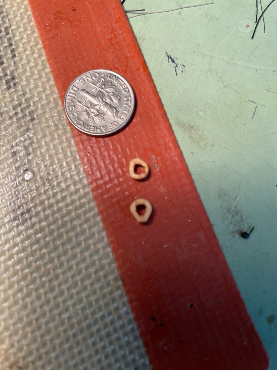
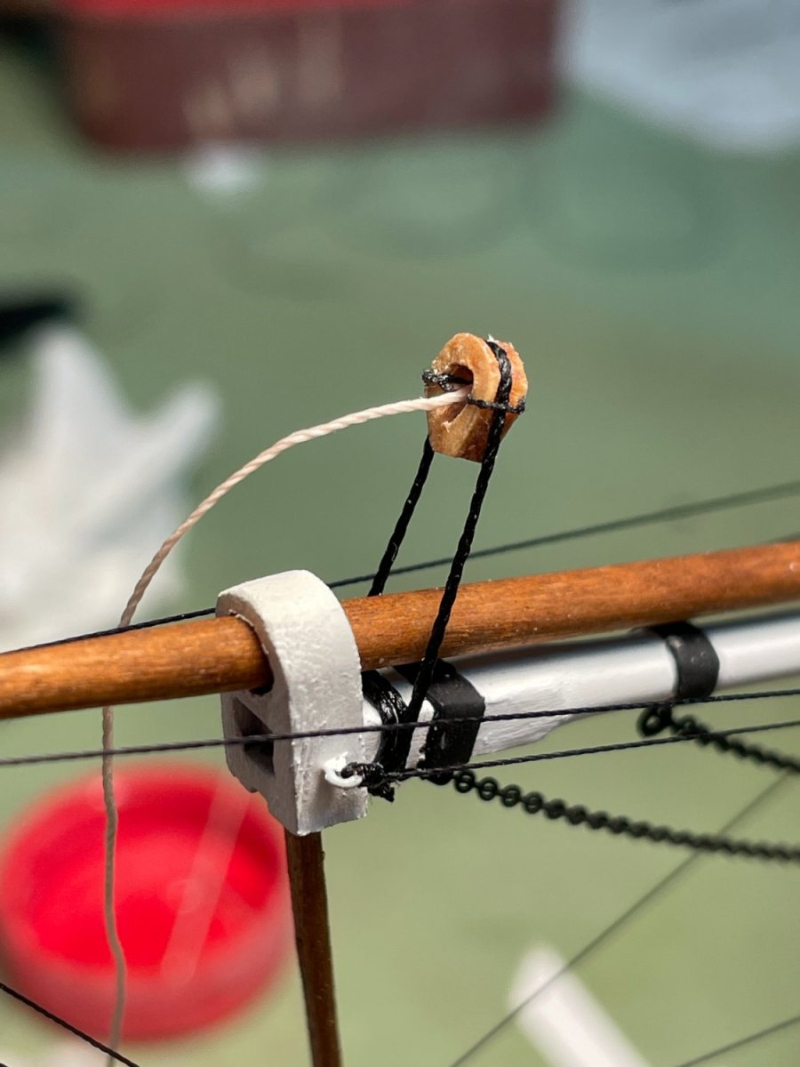
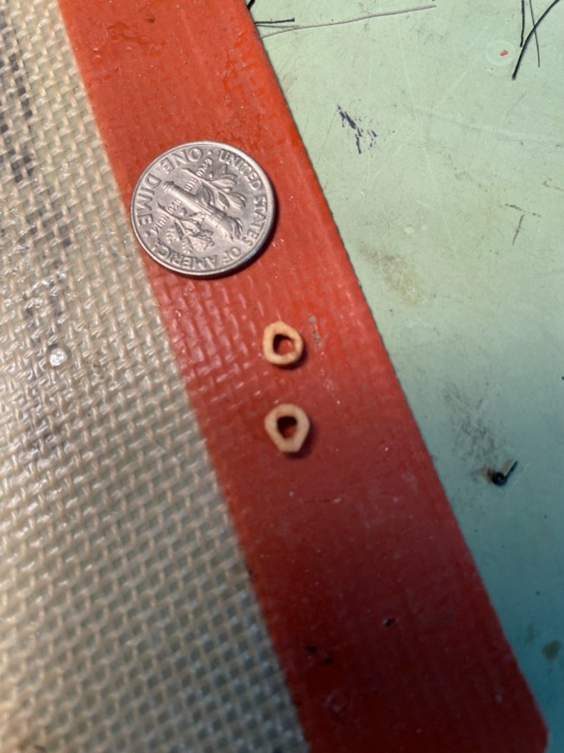
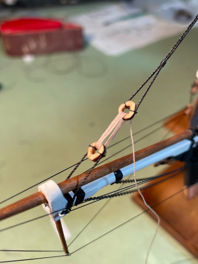
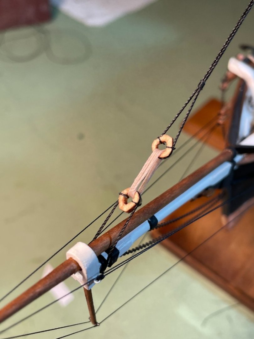
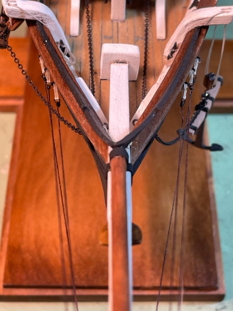
Part 2 Trying to follow all the Superdetails listed in the instructions I decided I would try making the heart blocks for the Inner fore topmast stay. Cutting out two circles from scrap wood and with a little drilling, sanding and filing (and cursing) I finally came up with two blocks I was happy with. First block tied to the bowsprit. Lashing the two blocks together. Completed Inner fore topmast stay Happy with the way it turned out.

- 144 replies
-
- 6
-
-
-
- Harriet Lane
- Model Shipways
- (and 1 more)
-
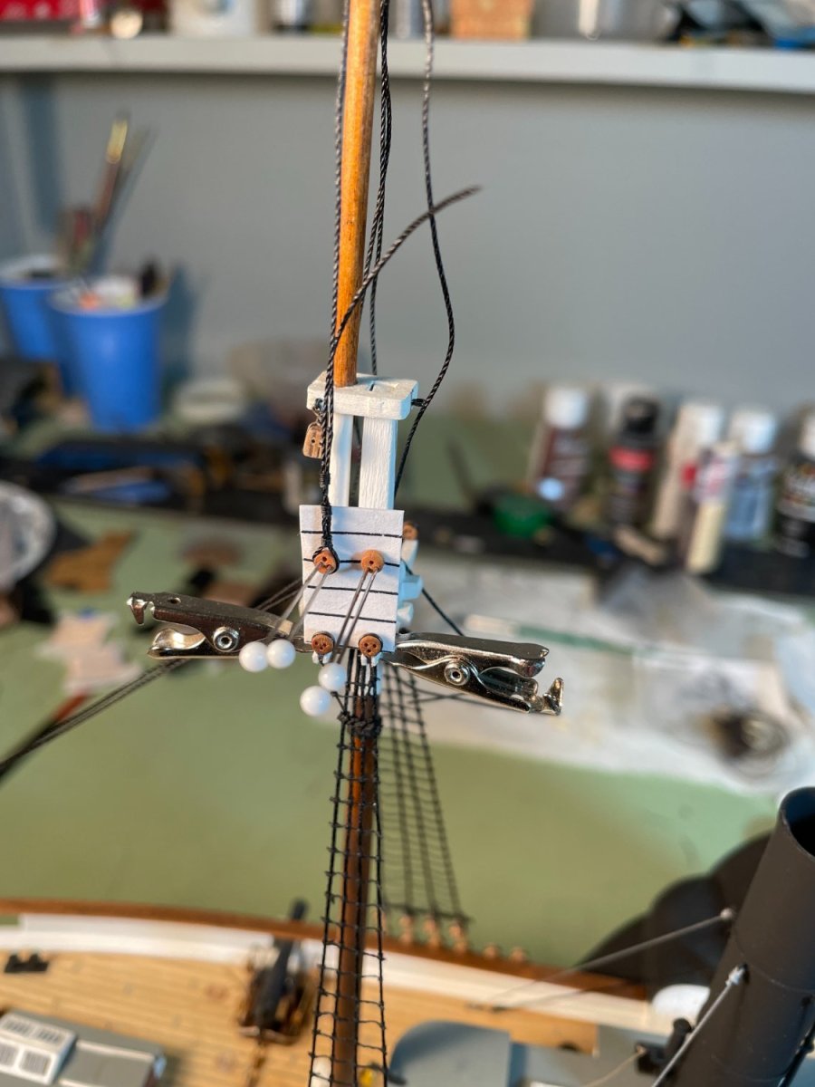
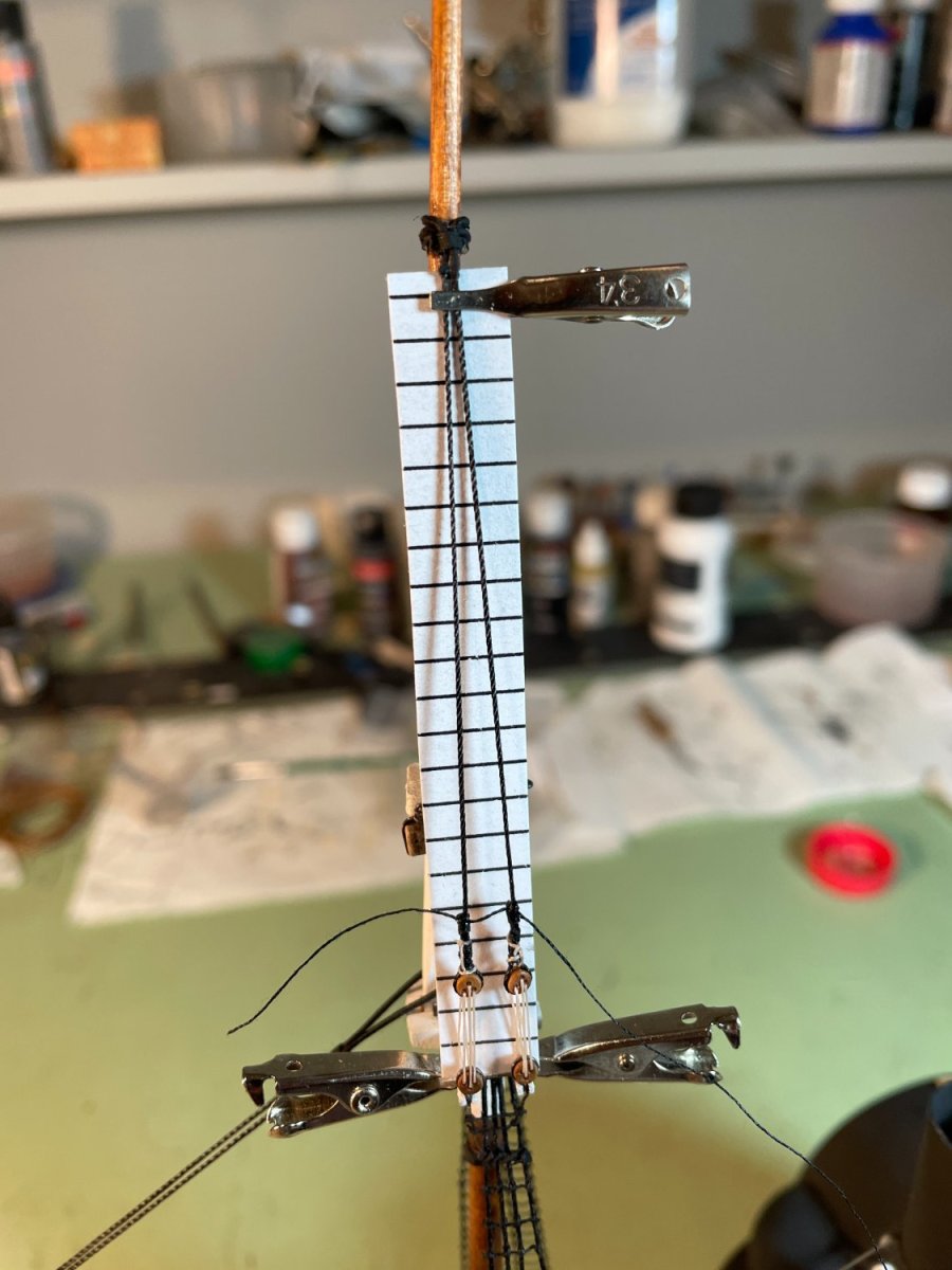
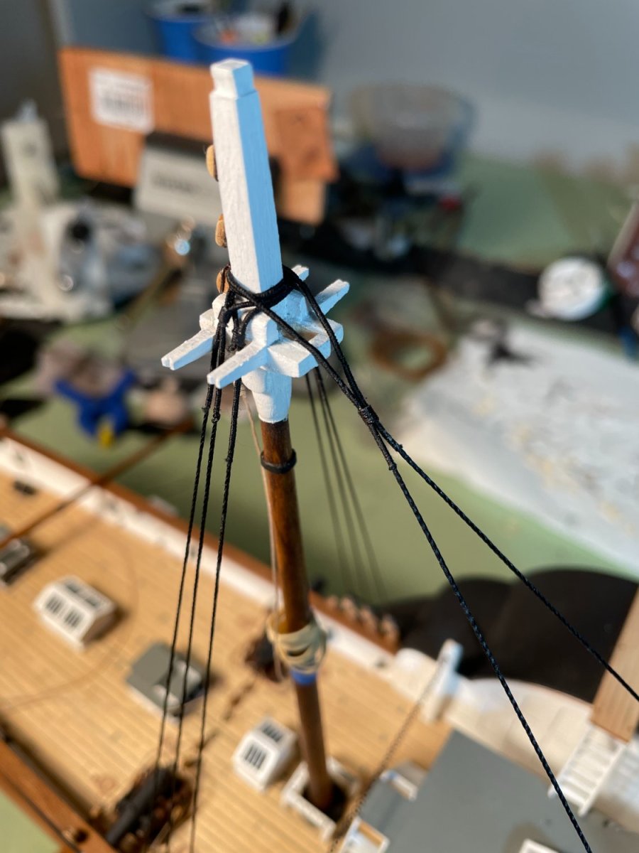
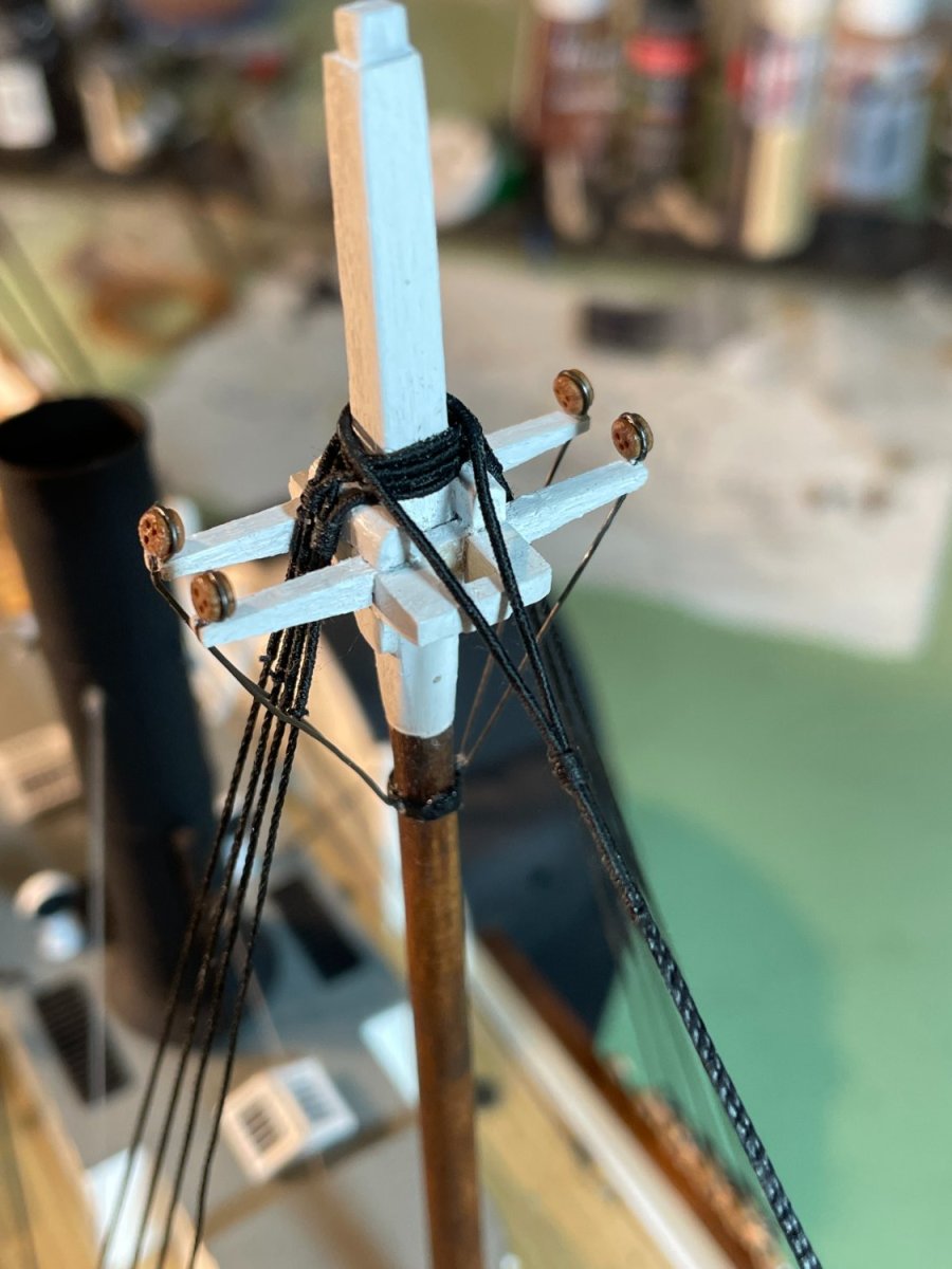
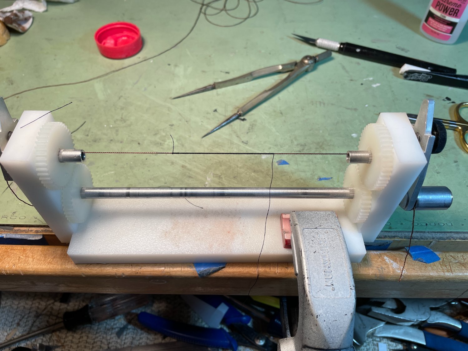
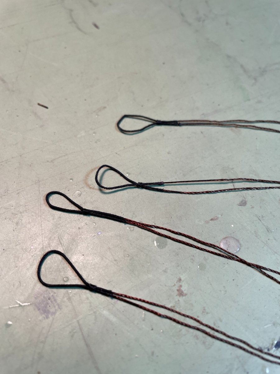
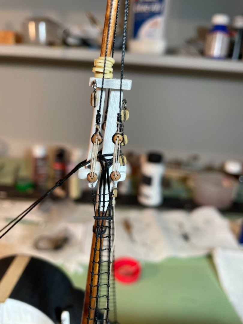
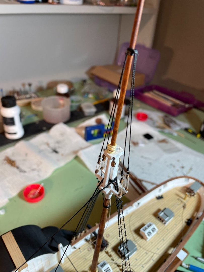
I’ve been a little delinquent in my postings so this will be a two part post which will be somewhat longer than my usual posts so I apologize in advance. Once all the lower rigging was completed and the futtock shrouds were installed the topmasts were mounted. The Topmast shrouds were installed the same way the lower shrouds were except for the way the deadeyes were held in place. These deadeyes were pinned to a piece of card stock that I had used for the lower shroud ratlines. The line spacing on the card stock just happened to be at the right distance for the deadeye spacing. After pinning the deadeyes to the card stock it was clamped to the crosstrees. The shrouds were then seized around the deadeye. I should also mention here that I chose to use a smaller diameter (2.5mm) deadeye for the upper shrouds than the 3.5 mm diameter deadeye that was provided with the kit. I just liked the looks of the smaller deadeye for the upper shrouds. The lanyards were then reeved through the deadeyes and rattled up. Completed shrouds. The ratlines for the fore topmast shrouds were tied the same way the lower ratlines were done. The Fore topmast backstays were added next. The deadeyes were tied to the stays the same way the lower shrouds were done using the twisted wire spacing guide. Lanyards were then reeved through the deadeyes and tightened.


- 144 replies
-
- 3
-
-
- Harriet Lane
- Model Shipways
- (and 1 more)
-
nicely done Bob
-
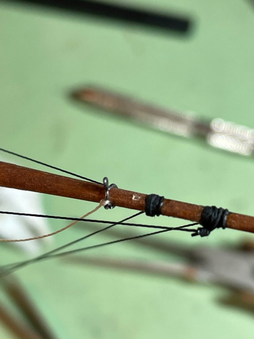
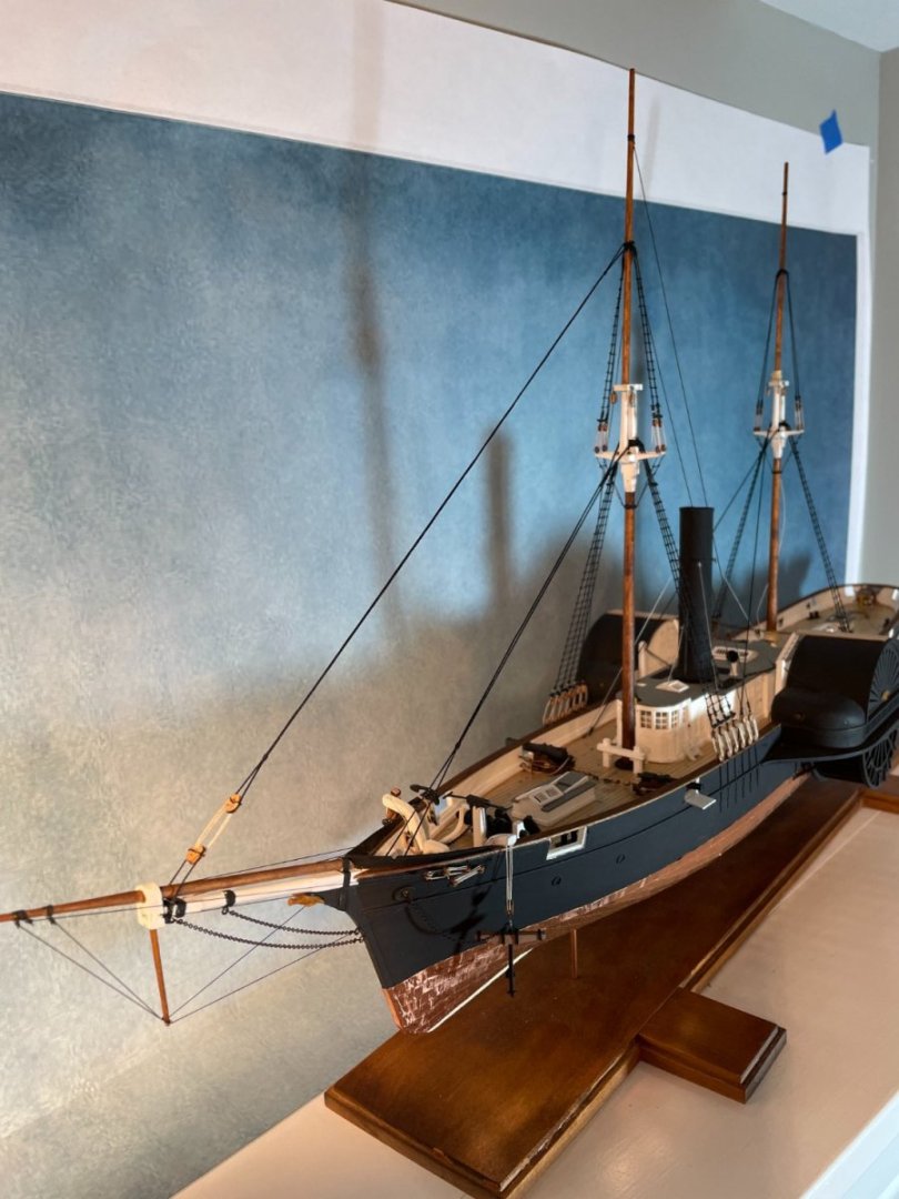
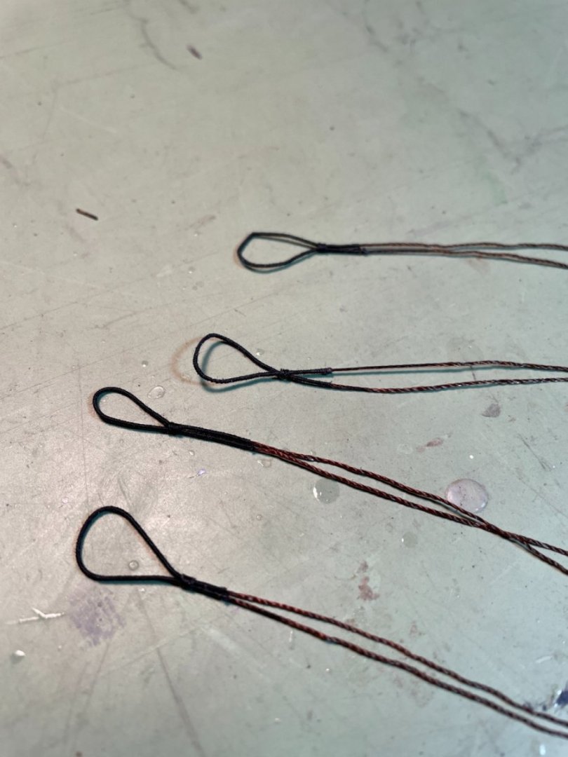
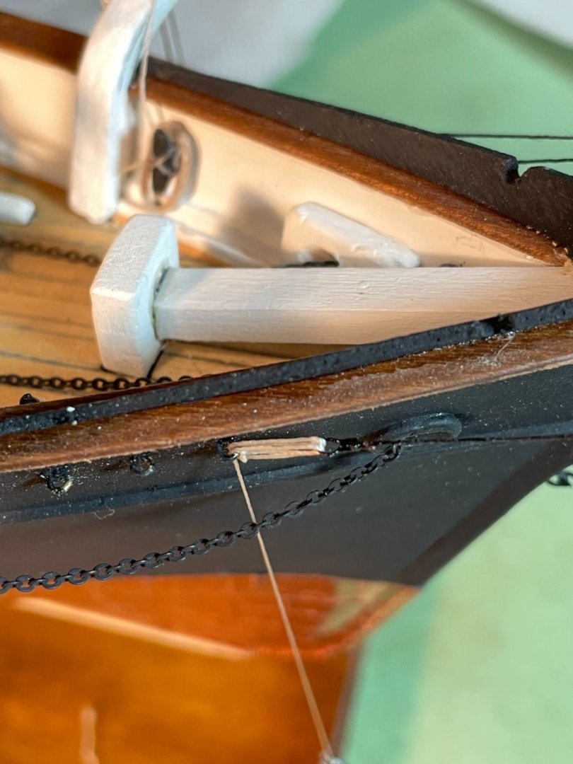
First Major Re-Do: While reading ahead in the instruction booklet on installing the ‘jib stay’ and ‘outer fore topmast stay’ I realized that I installed the starboard side martingale stays in the wrong place. I installed both the port side and starboard side stays at the same location on the jib boom (outer end). You can see this in my post #86, picture #6. I thought about just changing out the starboard side stay but since all the bow sprit rigging was done with the rope that came with the kit (brown) and all the rest of the rigging done after that (shrouds, main stay & fore stay) was done with non-kit rope (black) I decided to change out all the bow sprit rigging to black rope. Cutting all the lines All the lines were redone as before with black rope and now in their correct position.


- 144 replies
-
- 6
-
-
- Harriet Lane
- Model Shipways
- (and 1 more)
-
Thanks druxey, I'll give Barber a try. rcmdrvr that is not the rope provided with the kit, it was leftover from and older kit (~2013) I did but can't remember off hand what company it's from.
- 144 replies
-
- 2
-
-
- Harriet Lane
- Model Shipways
- (and 1 more)
-
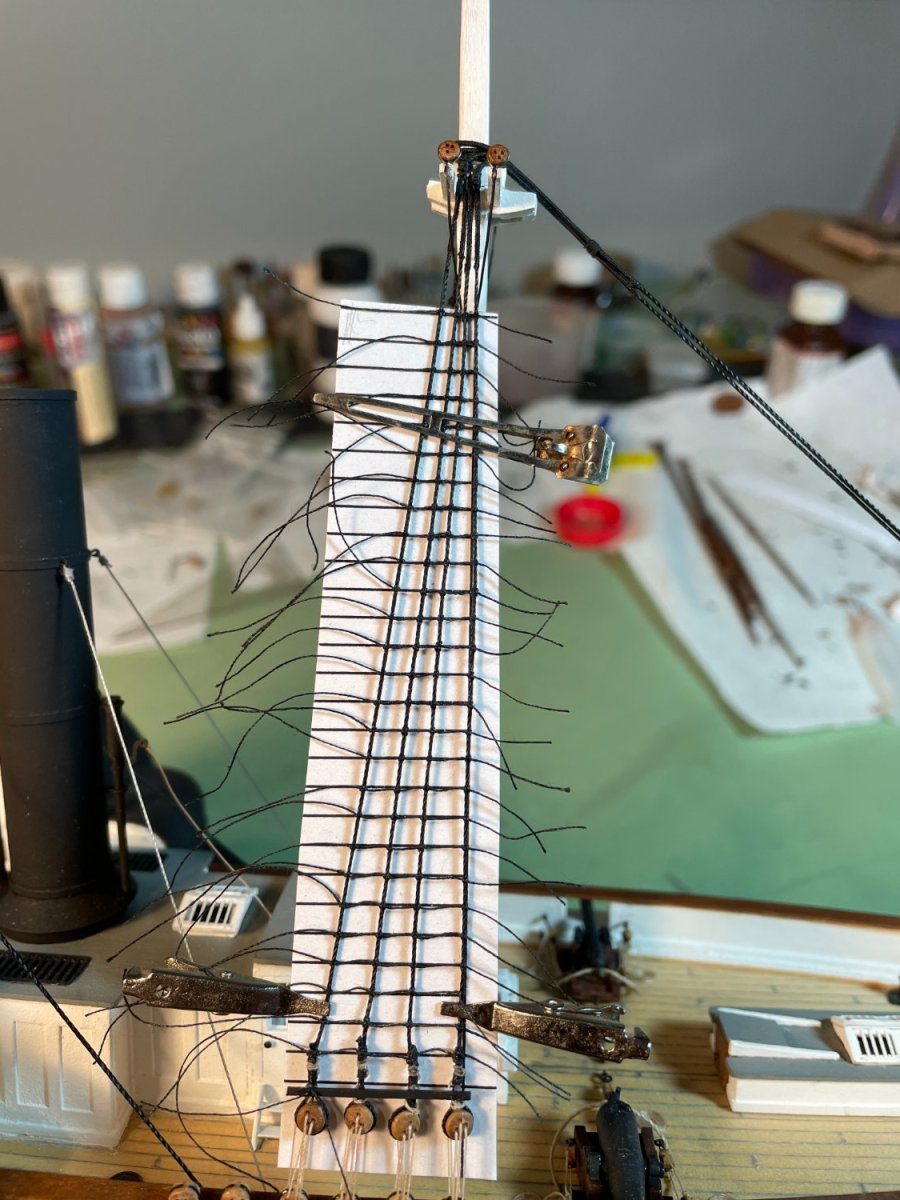
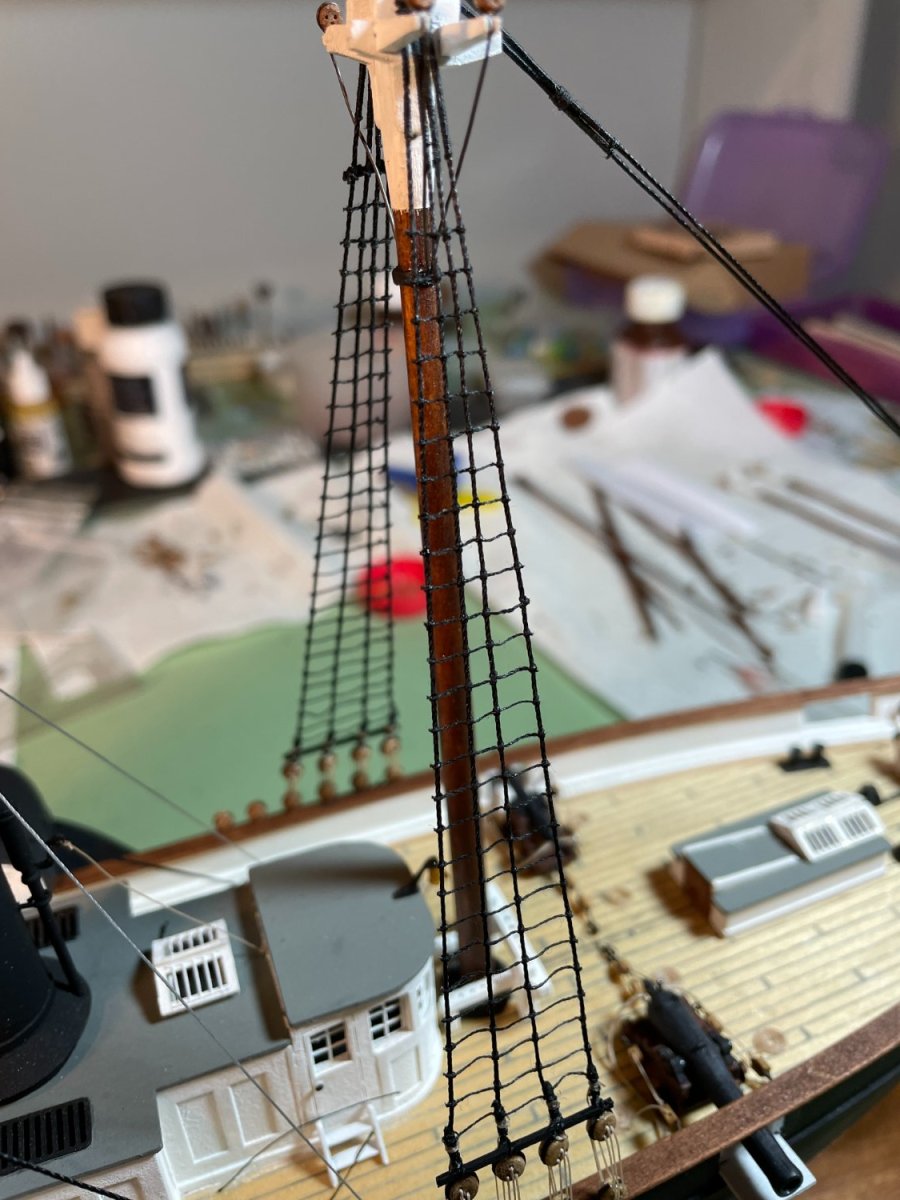
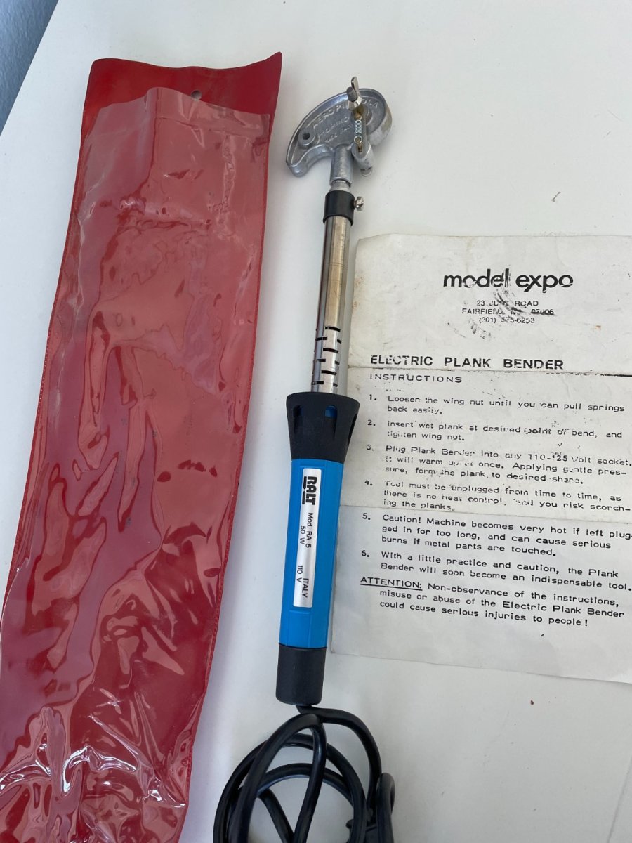
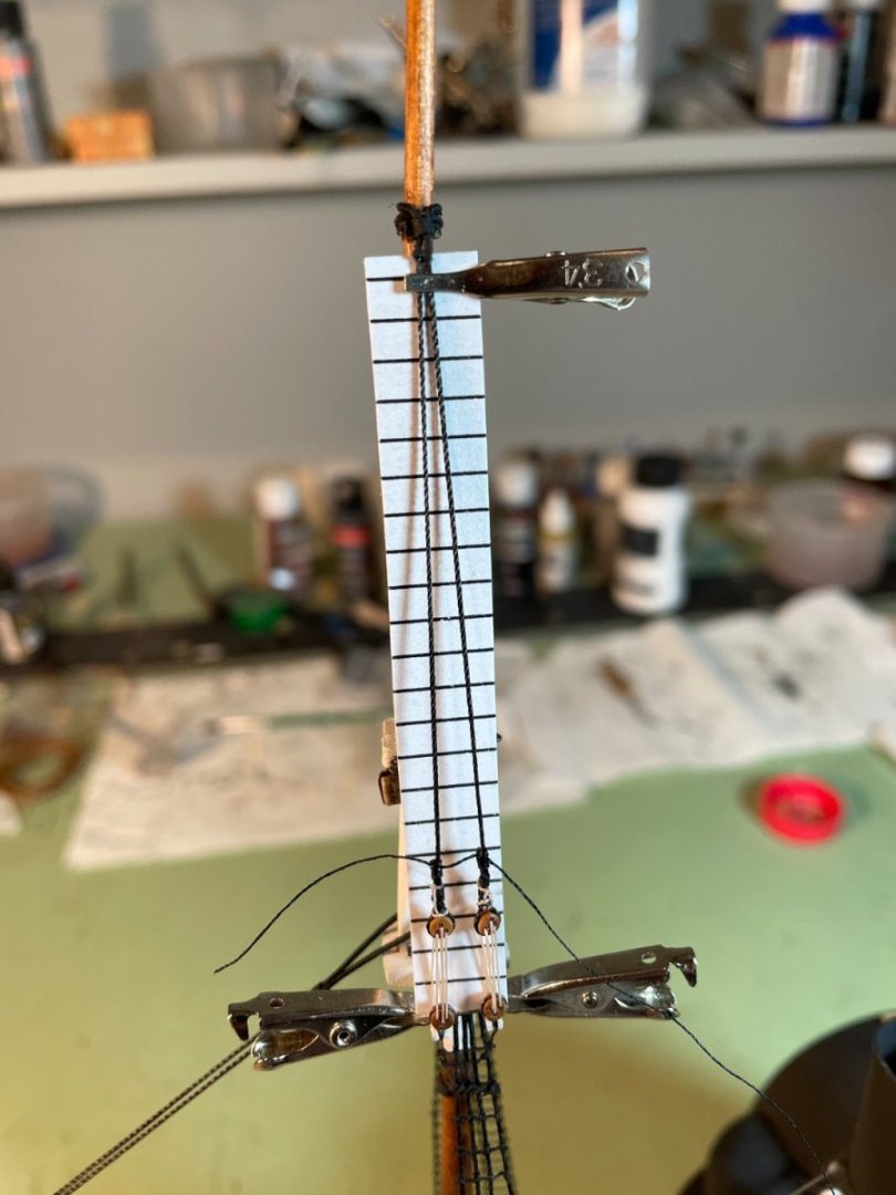
Ratlines: I decided to tie the ratlines onto the shrouds instead of gluing them because I had glued them on one of my other ships and wasn’t happy with the way they looked. I used a 14” (scaled) spacing on the guideline card that I printed out and clipped it to the shrouds to hold it in place. I started with a simple overhand knot on the first shroud followed by clove hitch knots on the remaining shrouds. Once the ratline was in its final position I put a small drop of ca glue on the knots to hold them in place. When all the knots were tied and glued I went over them with a bit of black paint to knock the shine off from the ca glue. I don’t mind a little sag in the lines because imo it gives it a more realistic look. There is one new thing I learnt while doing these. I normally listen to music while working on my ships and change the style of music by how I feel that day. Well I happened to be in the mood for some classical music the day I was working on the ratlines and I can tell you now do not try and tie ratlines to Korsakov’s "Flight of the Bumblebee", unless you want to finish them in about ten minutes.🐝 New toy I bought for myself for for my birthday. Can't wait to try it out.


- 144 replies
-
- 6
-
-
- Harriet Lane
- Model Shipways
- (and 1 more)
-
well done Craig, ditto on all the previous comments. I can almost hear her now being staged at the line.
-
druxey and rcmdrvr thank you both for the kind words, much appreciated. and thanks for all the likes.
- 144 replies
-
- 3
-
-
- Harriet Lane
- Model Shipways
- (and 1 more)
-
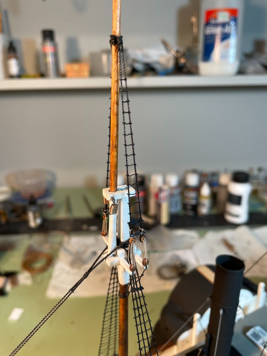
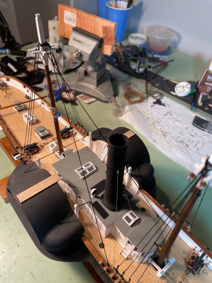
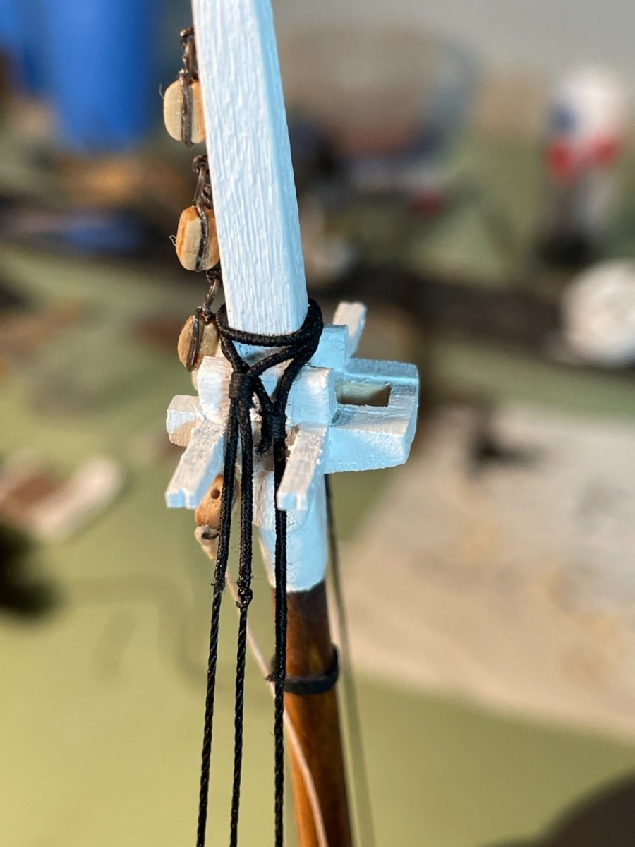
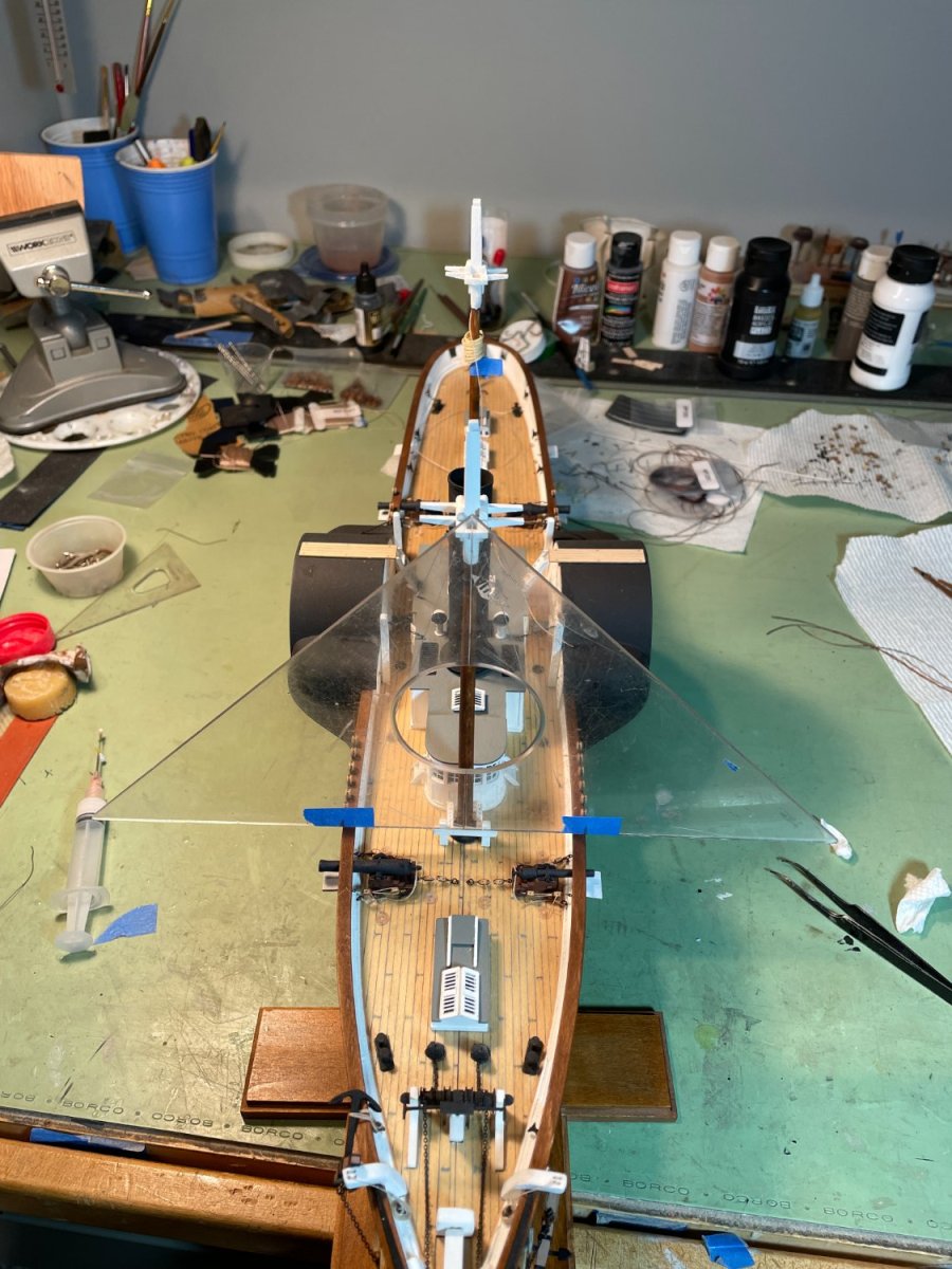
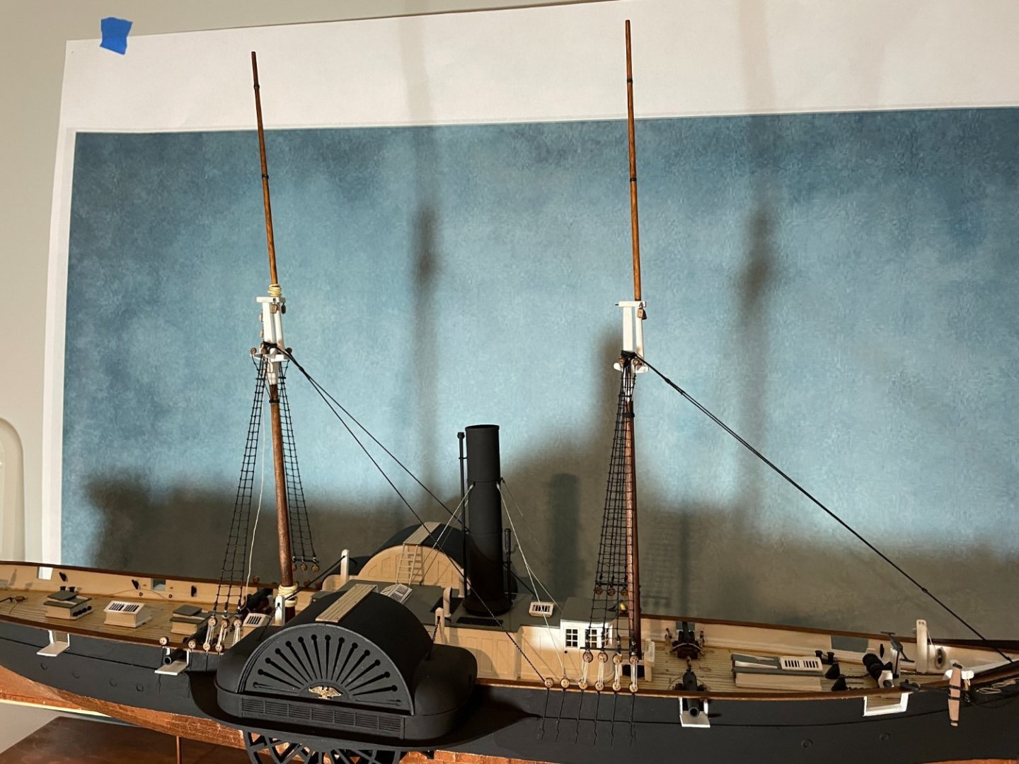
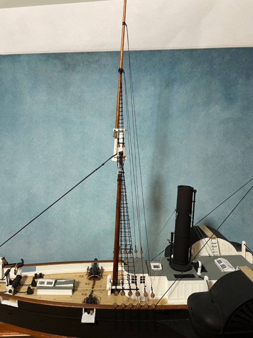
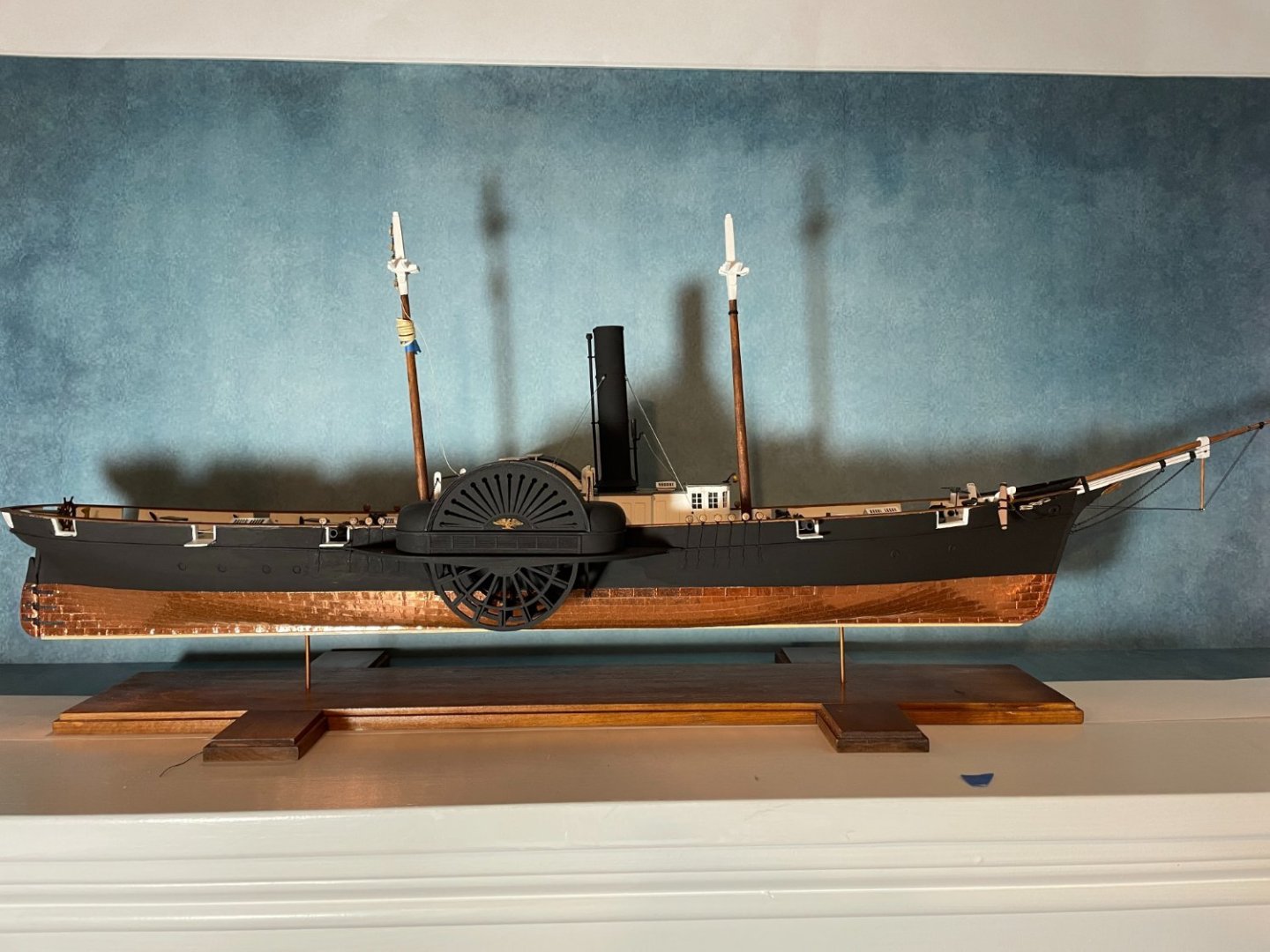
Moving right along the next few steps were pretty straight forward. Sheerpoles were glued in place. Main stay was served and installed around the masthead..... ....down to eyebolts on the deck Fore stay was served and installed. The futtock shrouds were also installed on the fore mast and I chose to make the these shrouds with 28 gauge wire glued to the crosstrees and set in a hole drilled in the mast. I'm not sure I would recommend doing this and just use thread as called for in the instructions because keeping the wire straight proved to be a challenge. Wire futtock shroud Overall state of the rigging to date.


- 144 replies
-
- 9
-
-
-
- Harriet Lane
- Model Shipways
- (and 1 more)
-
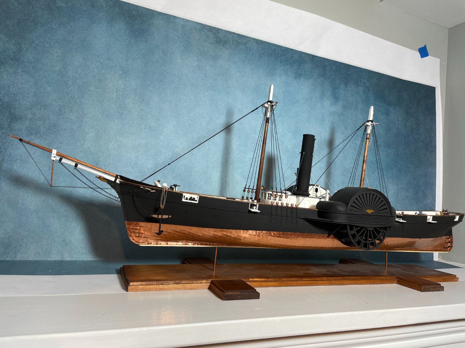
A blast from the past. I'm pulling up a seat an reminiscing.
-
Big improvement over the old base, well done.
-
Thanks Jack and for the likes. This is the first kit that I've purchased that the cordage is not up to par and to top it off there really isn't that much of it required. I don't know if Model Shipways is tying to cut costs but even the eyebolts they supplied with this kit are inferior to the ones they use to provide. Personally, like I've mentioned before, I like to try and use the material that comes with the kit since these kits are not cheap and I am.😁
- 144 replies
-
- 4
-

-
-
- Harriet Lane
- Model Shipways
- (and 1 more)
-
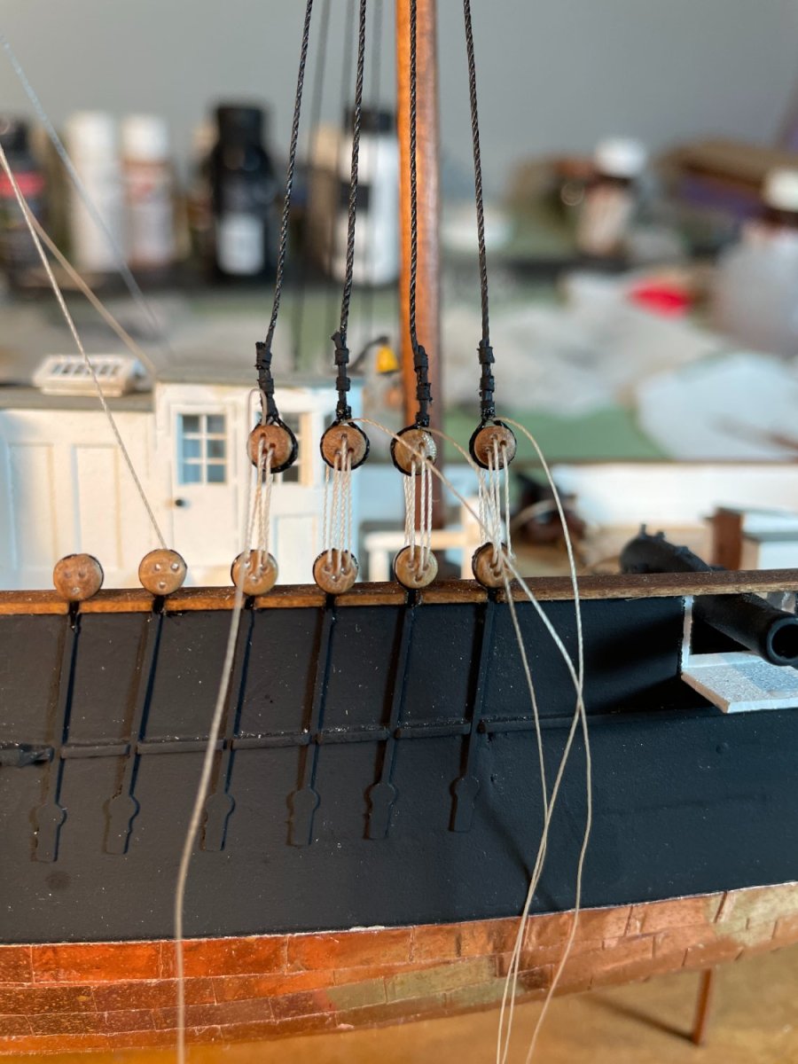
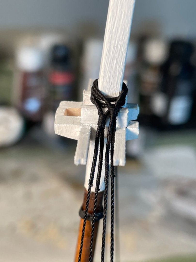
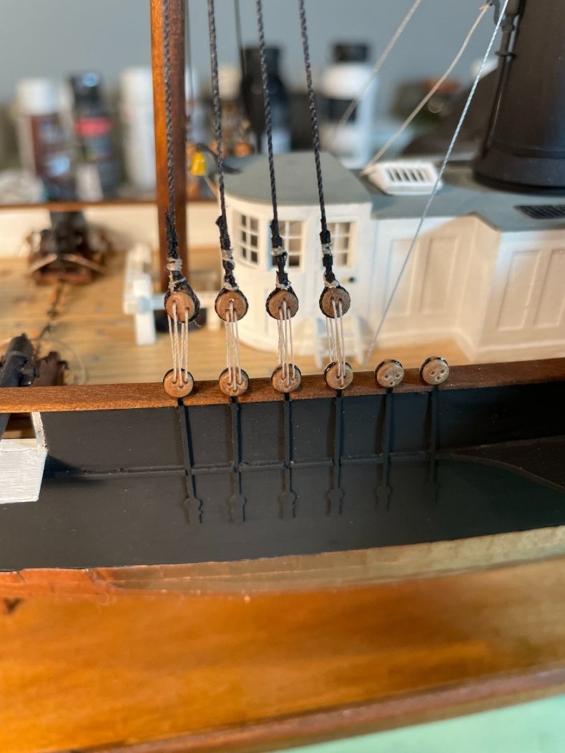
Shrouds and deadeyes: I have a small serving machine so I decided I would serve the center of the shrouds where they wrap around the mast heads. Served shroud pairs I made a little jig, made up of twisted wire, that held the upper deadeye in position while the shroud was tied around it. After tying the first shroud I decided that I did not like the looks of the thread (rope) that was provided with the kit. Fortunately I had extra rope left over from a previous build that I was able to use. I served these lines and placed then around the mast heads. Four pairs around the fore mast head, and two pair and a single around the main mast head. After tying all the deadeyes into position the lanyards were threaded through them. I used a lighter thread for the lanyards to distinguish the standing rigging from the running rigging. Completed fore mast deadeyes Completed main mast deadeyes Personal opinion: I don’t know how much more this kit would have cost if a little better cordage was provided but imo it would have been worth it.


- 144 replies
-
- 10
-
-
- Harriet Lane
- Model Shipways
- (and 1 more)
-
Hi Chris, it's an HP 11C. The 11C was their scientific calculator, was the 15C for accounting? I can't remember. I always preferred HP's and their RPN.
- 144 replies
-
- 1
-
-
- Harriet Lane
- Model Shipways
- (and 1 more)
-
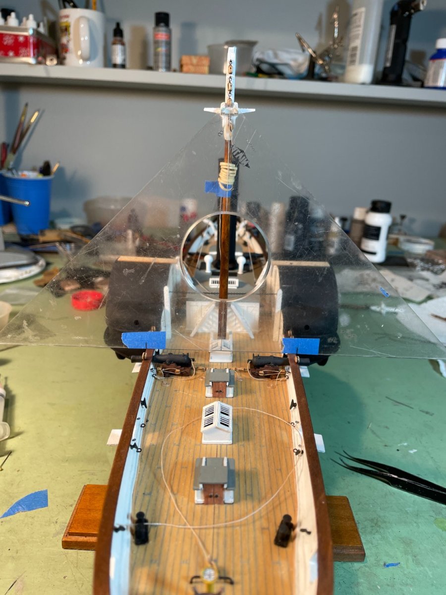
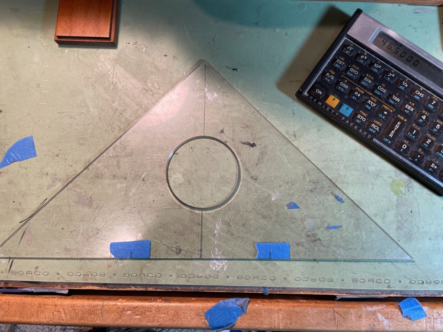
Stepping the masts: Personally I like to glue the masts into their final position so I don't have to worry about plumbing them with the shrouds. To help align the masts I find that a 45 degree drafting triangle comes in handy. I use the triangle to help me plumb the mast athwartship. First I scribe a line in the plastic triangle bisecting the 90 degree angle and perpendicular to the hypotenuse. Then I measure the overall distance athwartship from the outboard edge of each cap rail where the triangle will be placed. Dividing that distance in half I mark that distance on either side of the scribed line along the hypotenuse of the triangle. Then standing the triangle up against the mast and with the two marks at either edge of the cap rail the apex of the bisected 90 degree angle will be centered on the ship and 90 degrees to the deck. I use white glue to give me time to adjust the mast to it's final position. Side view. Both fore and main masts were done the same way. The advantage I find with this method is that the ship doesn’t need to be leveled. As long as the ship is built with a reasonable amount of symmetry and the triangle is properly placed across the rails then the apex of the triangle will always be at the center of the ship and 90 degrees to the cap rails (deck). Stepped masts


- 144 replies
-
- 6
-
-
- Harriet Lane
- Model Shipways
- (and 1 more)
-
Thanks druxey, I did finally use a small drop of ca glue at the pin location after tying the lines to keep them from coming off.
- 144 replies
-
- 2
-
-
- Harriet Lane
- Model Shipways
- (and 1 more)
-
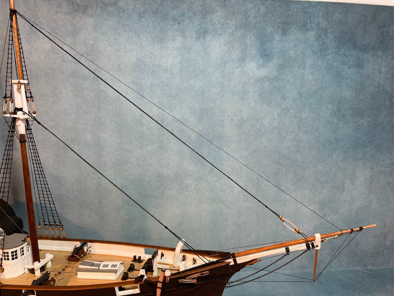
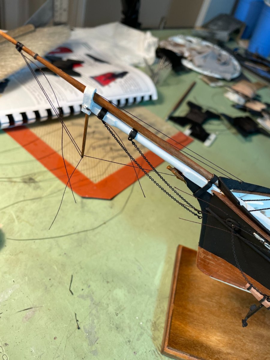
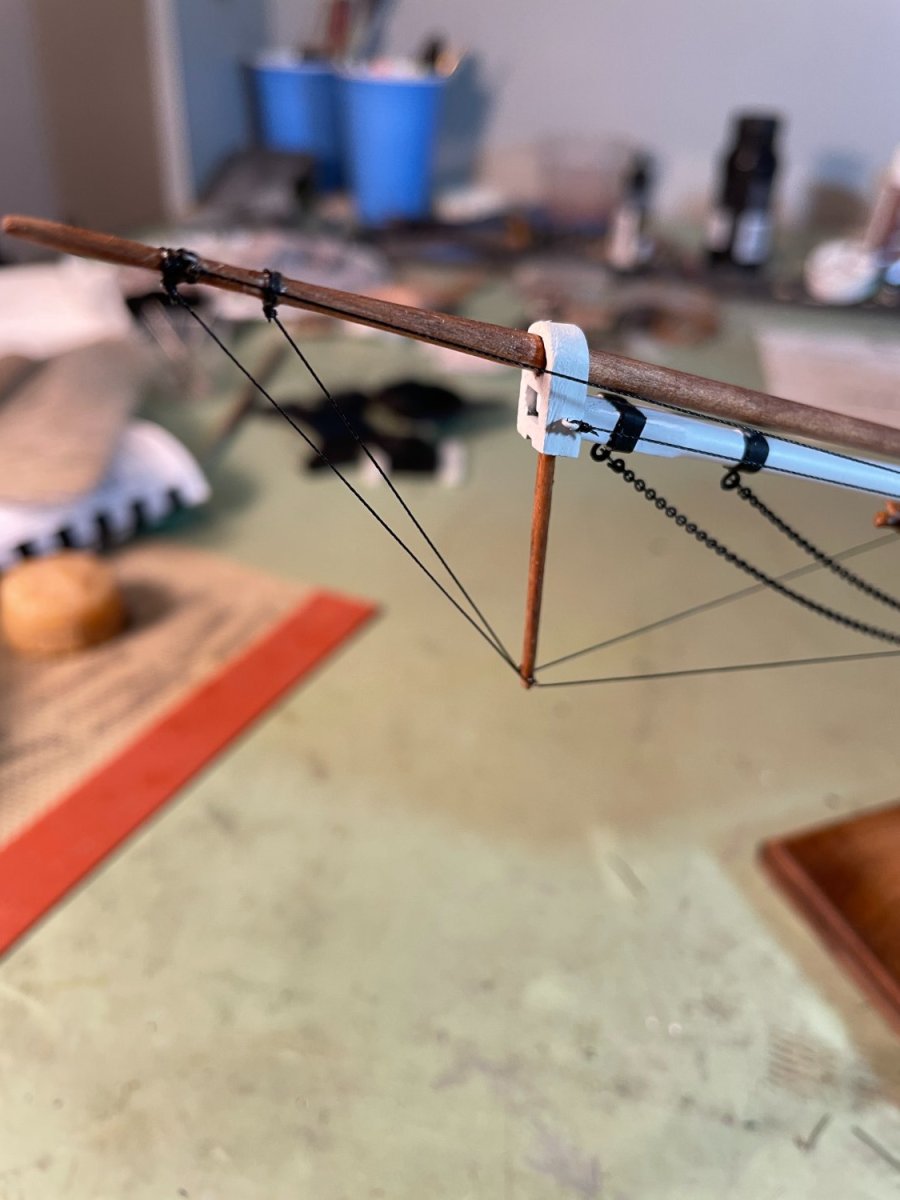
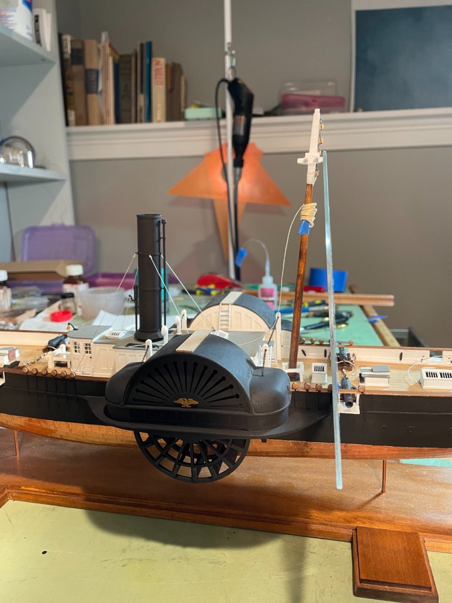
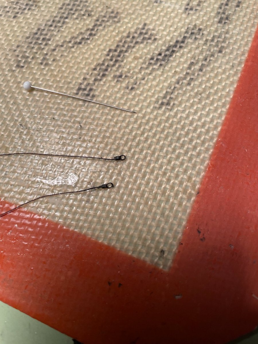
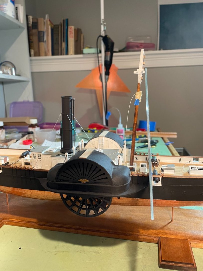
The jibboom and striker were installed so now I have something to break off. I think I broke the striker off my Syren three times while I was building it. I added an additional gammoning strap made of card stock to secure the jibboom. For the bowsprit rigging I decided to try the super detail mentioned in the instructions to simulate the lanyards at the inner end of the stays and shrouds. To do this I first siezed an eye loop at the end of the stays and shrouds, stiffened with ca glue. After attaching the outer ends of the stays and shrouds to the jibboom and cap I connected the inner end to the eyebolts attached to the bow by lacing thread through them and the stiffened eye loop. (I think it's time to dust my ship) Completed bowsprit rigging Note: I found it very hard to keep the rigging for the martingale stays under the pin at the bottom of the striker while tying these lines. Maybe I didn't make the pin long enough.


- 144 replies
-
- 5
-
-
- Harriet Lane
- Model Shipways
- (and 1 more)
-
Thanks Snug Harbor Johnny, I try to use all the material that comes with the kit, since they do cost a lot, without spending more on after market parts. If I was to scratch build I would definitely use Chuck's products.
- 144 replies
-
- 2
-
-
- Harriet Lane
- Model Shipways
- (and 1 more)
-
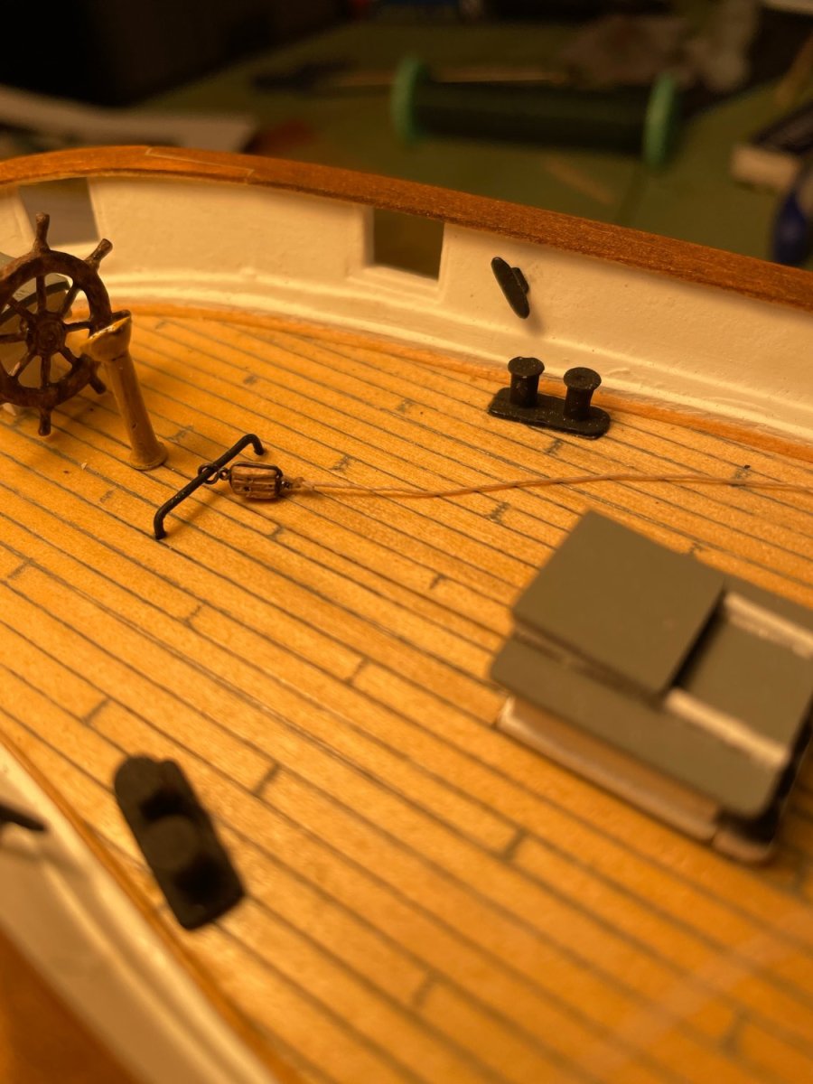
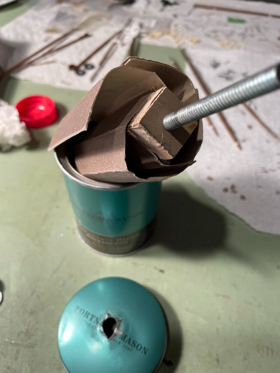
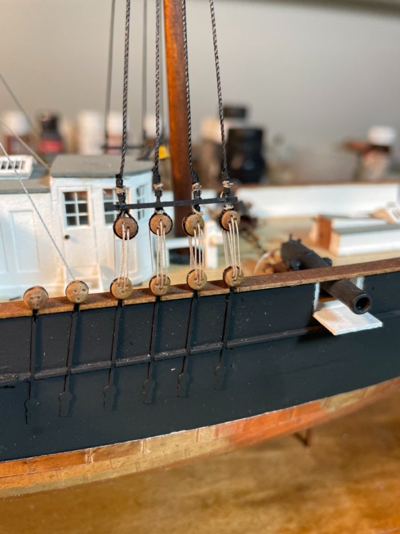
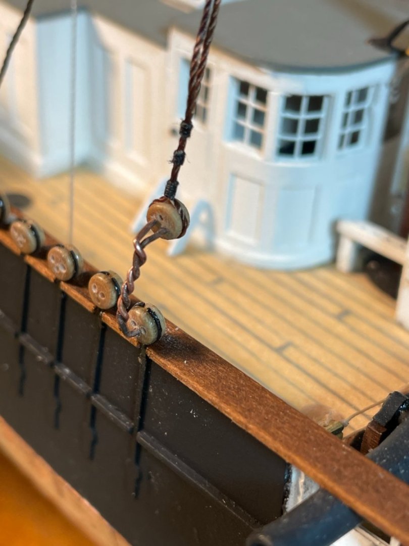
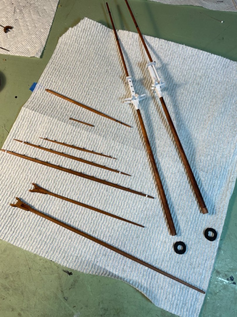
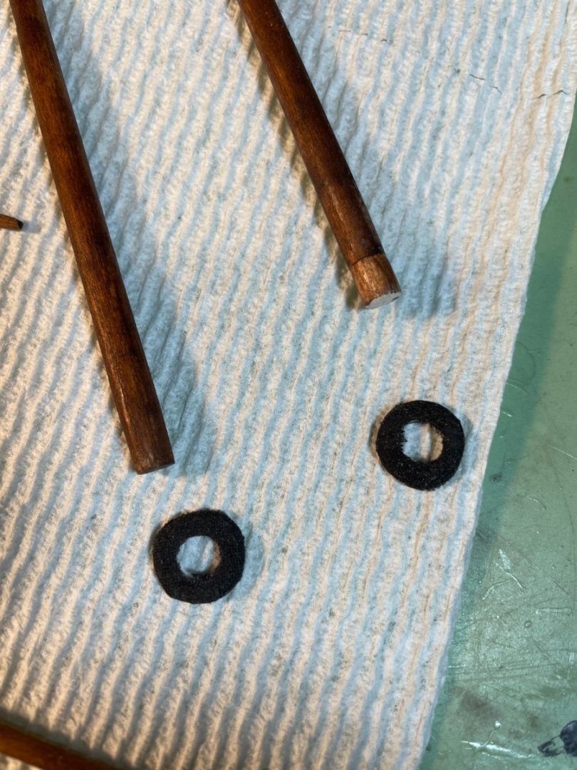
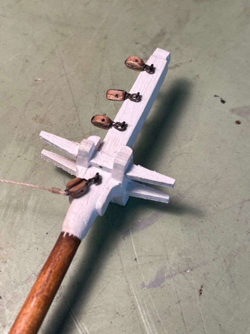
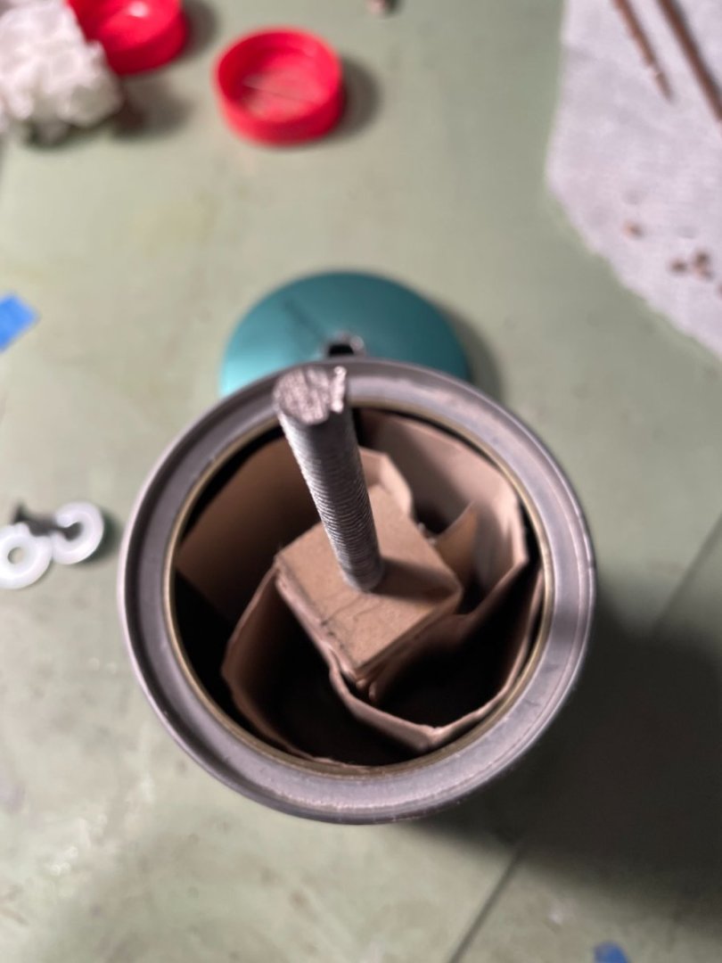
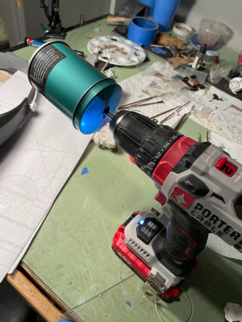
The jibboom, gaff, boom and striker were all sanded down according to the plans as were all the yards. Eyebolts and card stock were added where called for. All the pieces were stained and the mast heads were painted white. I also made up two mast coats for the masts by cutting out little wooden donuts and then covering them with cloth from an old handkerchief, painted black to simulate tar. Blocks were added to the main mast. The traveler with its block was also added. The instructions mention that the looks of the blocks can be improved by filing the corners off making them more oval shaped. Sounds kind of hard for big fingers especially for those 3/32" blocks so I thought I would share how I do it. I have a small can that is lined with 180 grit sand paper. Into the can goes a wooden spool that I have attached four pieces of 220 grit sandpaper and a threaded rod. The blocks are placed inside the can, the top is put on and I spin it with an electric drill. You need to play around with it to know how long to go for but don't spin them too long or you'll end up with a pile of sawdust.


- 144 replies
-
- 7
-
-

-
- Harriet Lane
- Model Shipways
- (and 1 more)