_SalD_
-
Posts
853 -
Joined
-
Last visited
Content Type
Profiles
Forums
Gallery
Events
Everything posted by _SalD_
-
 I am trying to find a better picture of the eagle emblem shown below, preferably in color. I've been searching the web but to no avail so far. Size doesn't matter (or so they say) because I can always shrink or enlarge it. I would appreciate it if anyone could point me in the right direction. Thanks.
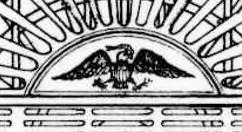
-
rcmdrvr you're moving right along, you'll probably be finished before I get my deck down. Everything looks terrific and thanks for the detailed write up. It will come in handy when I get to that step in my build. I'm not sure if it's too late but to cover up the deck etchings around the perimeter of the deck house can you install a base board all around to cover them?
- 25 replies
-
- 1
-

-
- Harriet Lane
- Model Shipways
- (and 1 more)
-
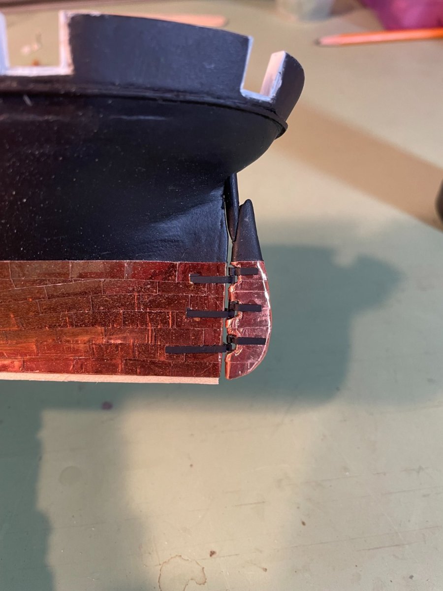
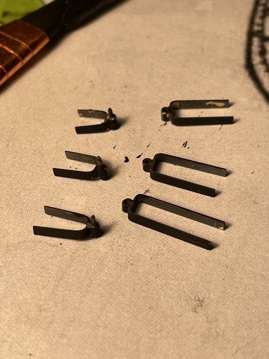
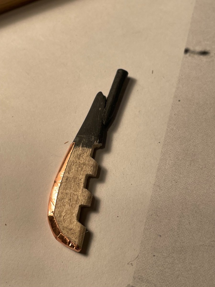
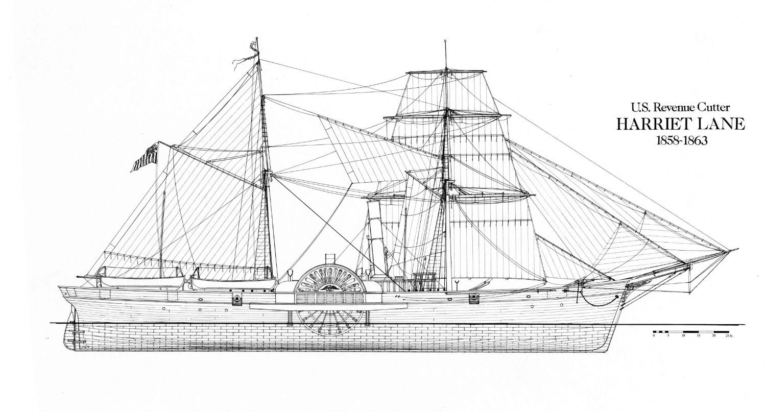
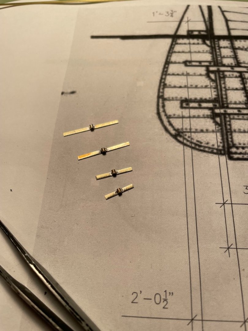
The rudder I decided to go back a few steps and install the rudder on the ship. I also decided that in lieu of using paper strips for the pintles and gudgeons as called for in the instructions, I would make my own. I started by cutting some 1/16” wide brass strips to a length that I scaled off the drawing shown in my post #29. To those strips I soldered pieces of 1/16” diameter brass tubing. The pintles were bent to fit around the rudder and the gudgeons were bent to fit the hull. Pins were glued into the pintle tubing to complete the hinge. The pieces were then blacken. The rudder had to be reworked by cutting in notches to made room for the hinge assemblies. The rudder was installed by gluing the pintles and gudgeons to the rudder and hull. I also added a false keel to provide protection for the copper plating.


- 144 replies
-
- 4
-
-
- Harriet Lane
- Model Shipways
- (and 1 more)
-
Ship goods great. I like what you did with the paddle wheel colors, I wasn't crazy about the all black either.
- 25 replies
-
- 1
-
-
- Harriet Lane
- Model Shipways
- (and 1 more)
-
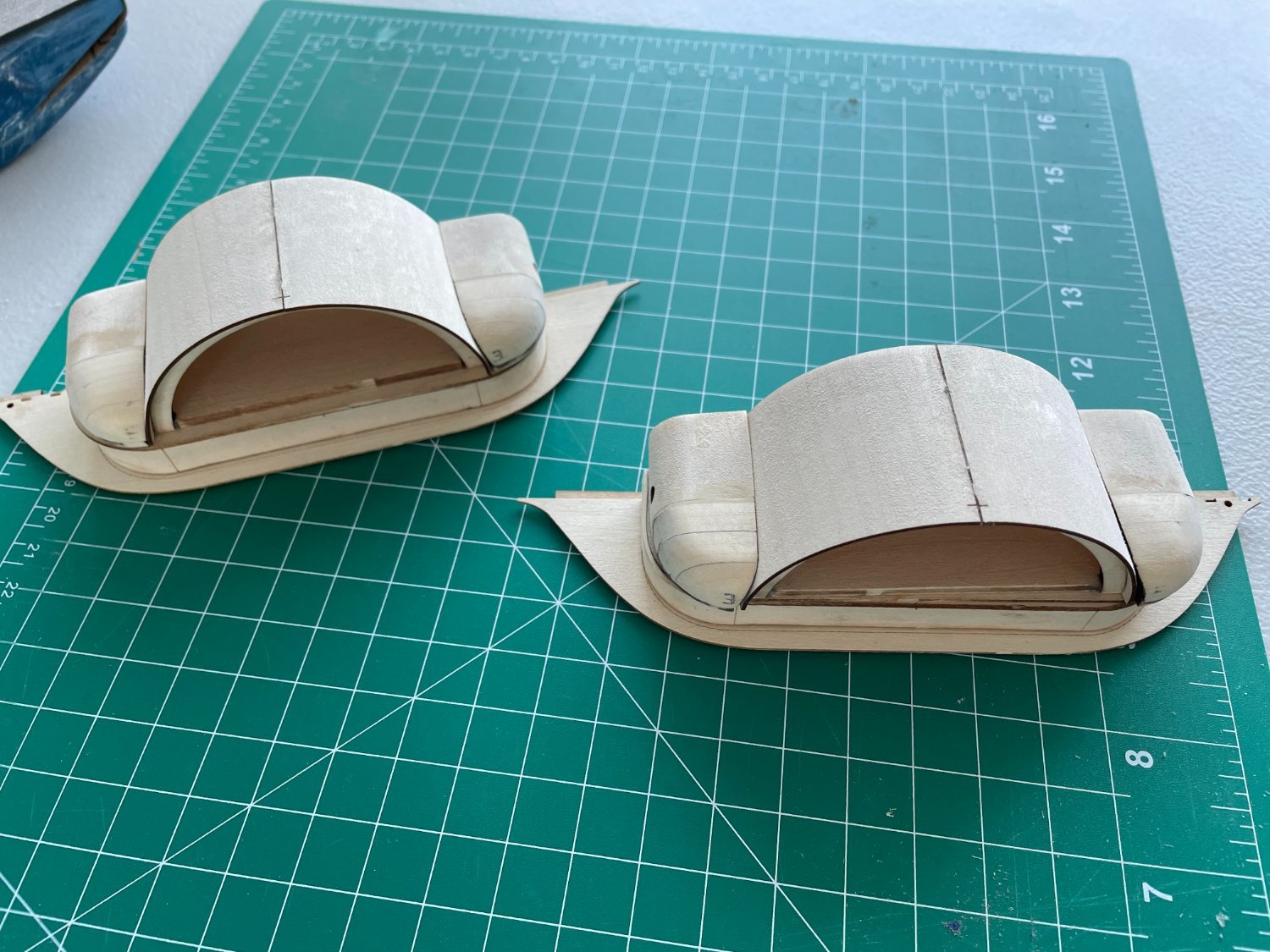
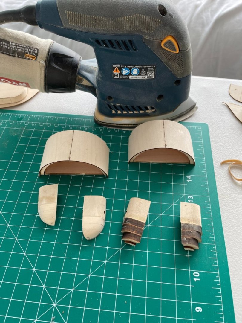
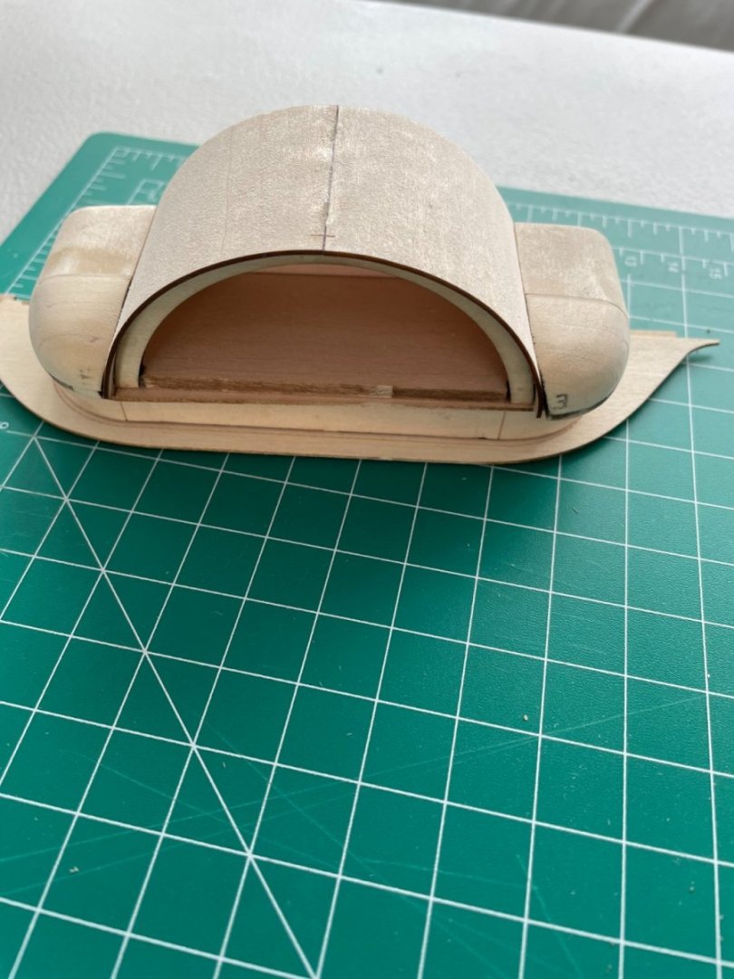
Paddle box upper sections and Water closets: The upper paddle boxes and water closets were assembled using the mini-miter box again to keep the pieces square. The paddle box covers were shaped and glued. Covers were shaped to fit using the stream iron after the top end was glued to the paddle box frame. The water closet sections were glued together and sanded as per the instructions using my favorite sanding tool. The sander works well you just need to be careful and not be too aggressive. I use 240 girt paper Pieces dry fit together. My wife and I, and dog, will be driving back up to Connecticut for the summer soon, so this will be my last post for a while. Once there it shouldn’t take too long to get posting again.

- 144 replies
-
- 5
-
-
- Harriet Lane
- Model Shipways
- (and 1 more)
-
Thanks again rcmdrvr for the kind words. The reason I coppered the hull was, first, I find it enjoyable and second, if you believe it, I find it easier than painting. It's just a matter of personal taste.
- 144 replies
-
- 2
-
-
- Harriet Lane
- Model Shipways
- (and 1 more)
-
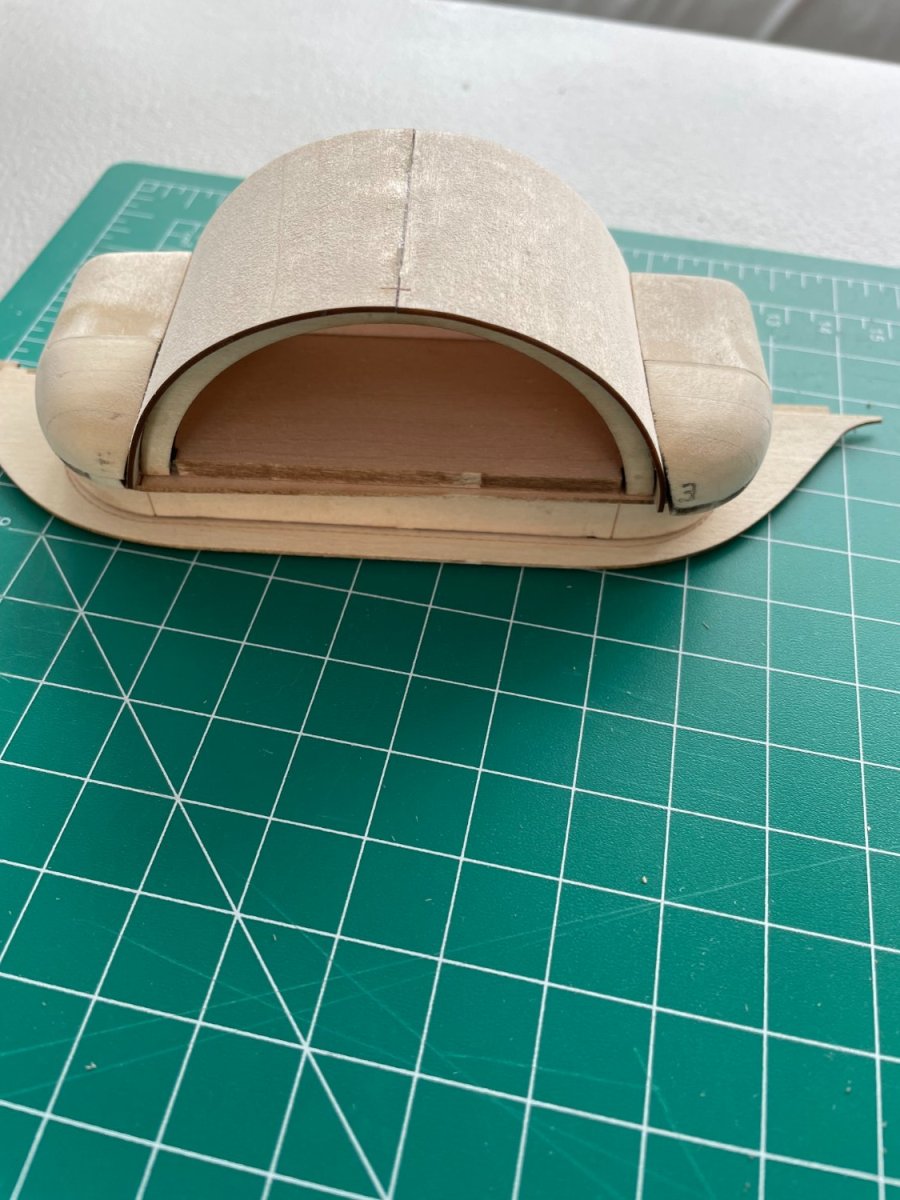
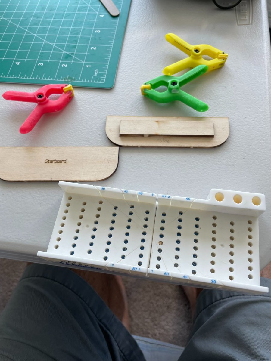
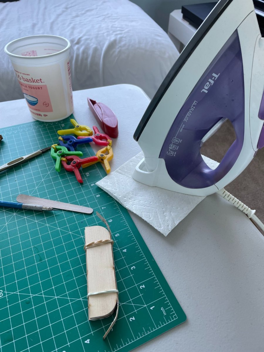
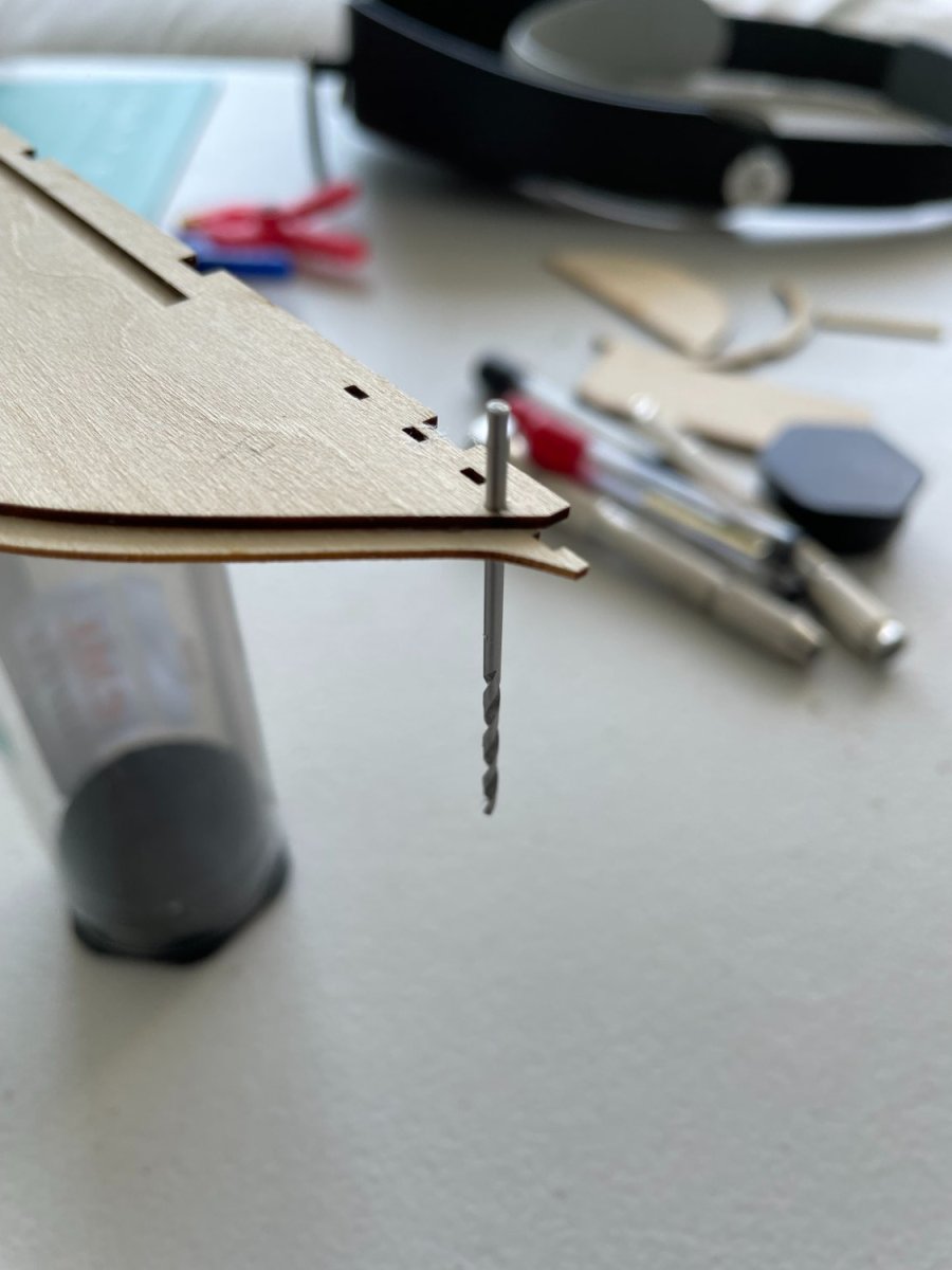
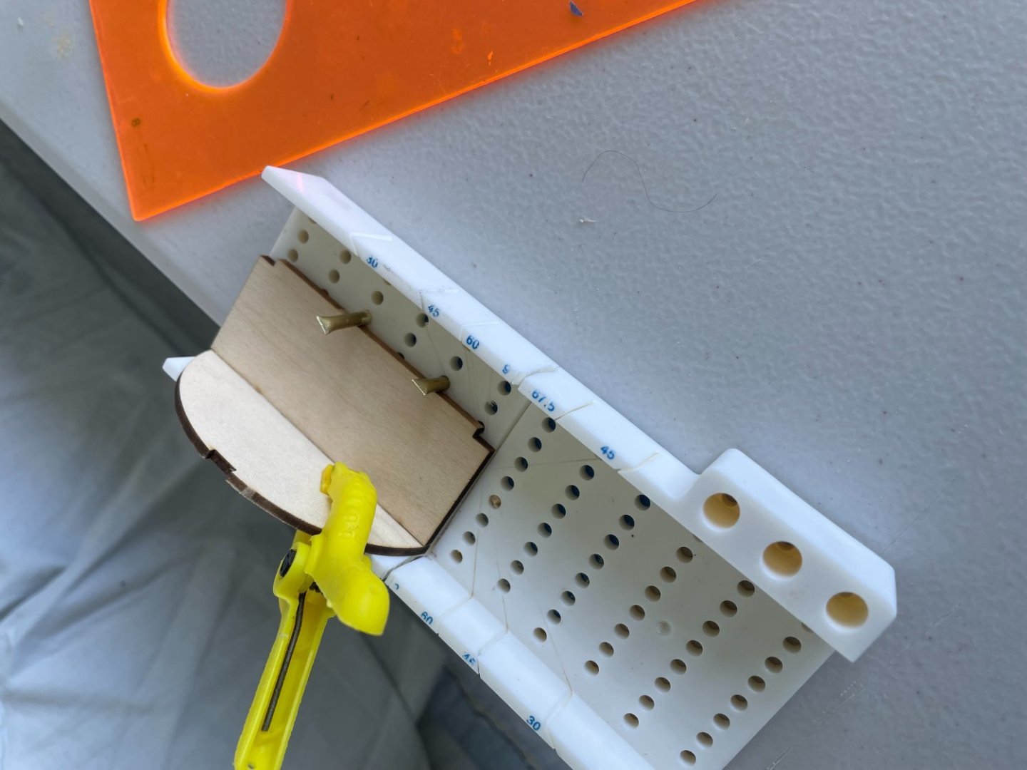
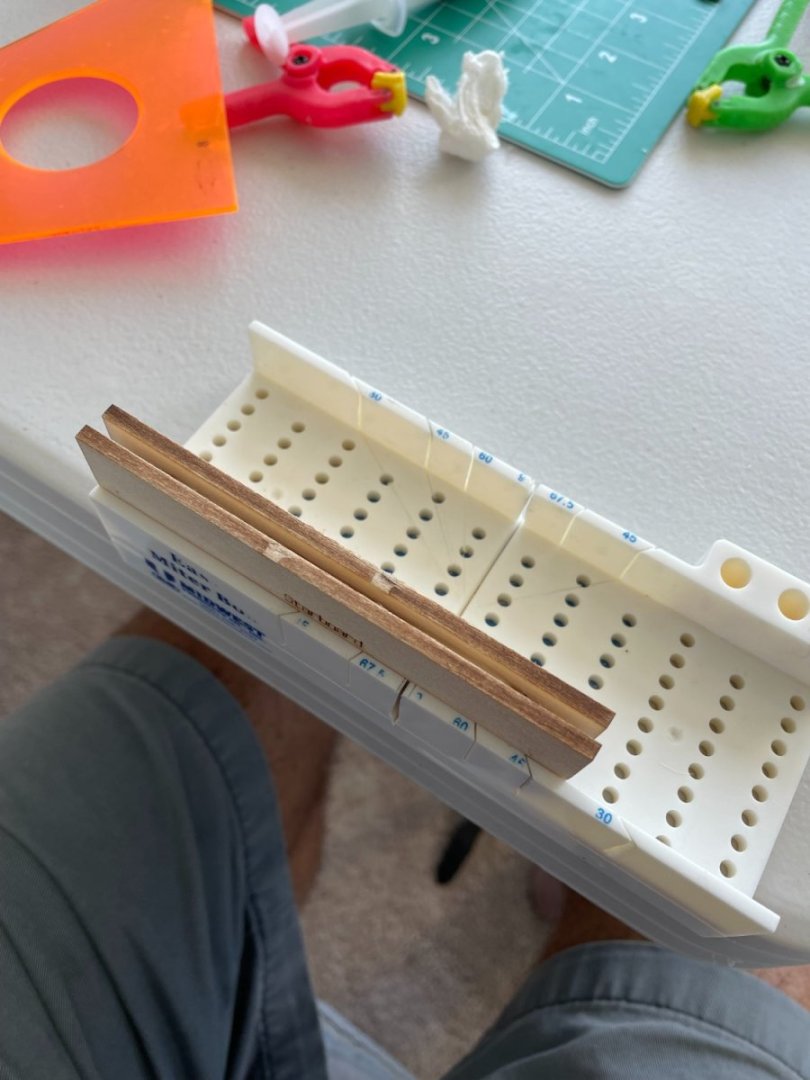
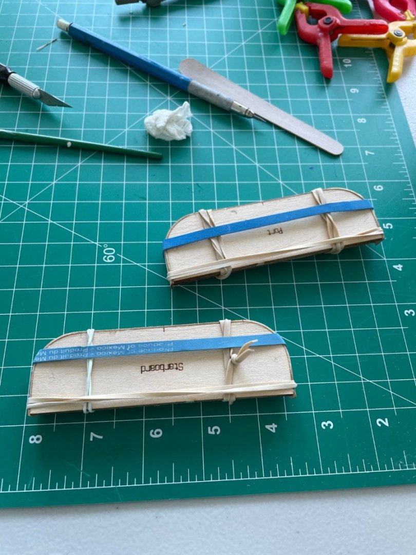
Paddle box lower sections: The lower paddle box sections are made up of two forming pieces separated by a spacer. Assembling these pieces is pretty straight forward, you just need to pay close attention to their correct orientation. Spacer glued in place. Glued the second forming piece to the spacer. Only thing I had to keep them lined up and vertical was my mini miter box. The wrapping pieces were centered and glued to the front of the paddle boxes. After the glue dried I used my wife's 'plank bender' to steam and bend the pieces to fit around the sides of the paddle boxes. Wrapping pieces were then glued to the sides of the paddle boxes and held in place with rubber bands. Sponson deck sections: While I was working on the paddle boxes sections I also glued the two sponson decks together. I wasn't quite sure which square holes to use to align these pieces as called for in the instructions because none of them seemed to line up properly. What I used was the small round hole at the end of the pieces that seemed to position the pieces in their correct orientation relative to each other. Used a drill bit for the alignment pin.


- 144 replies
-
- 6
-
-
- Harriet Lane
- Model Shipways
- (and 1 more)
-
Thanks Bob. I agree with you at this scale they would be too much. The seam roller. If you look at my post #29, the first photograph, the little tool, upper right side with the wooden handle is the seam roller.
- 144 replies
-
- 2
-
-
- Harriet Lane
- Model Shipways
- (and 1 more)
-
Thanks rcmdrvr. I find that the adhesive on the back of the tape is sufficient to hold it in place and don't use any additional glue. I use a wallpaper seam rolled to press the tape down after it's set in place. I personally have not sealed the copper plating on any of my ships and it seems to hold up well. I know other people who do, so I think it's a matter of personal taste to seal or not to seal. One thing you do have to be careful of is to not touch the copper with your bare fingers, fingerprints are very noticeable. I always use latex gloves while putting the copper on and then try not to touch the bottom of the hull while doing other parts of the ship.
- 144 replies
-
- 4
-
-
- Harriet Lane
- Model Shipways
- (and 1 more)
-
Finishing up the copper plating: Complete except for the dressing belt. Dressing belt added. Rudder finished Dry fitting the rudder


- 144 replies
-
- 4
-

-
-
- Harriet Lane
- Model Shipways
- (and 1 more)
-
rcmdrvr, just found your build and I will be following along. I had the same problem with the upper counter warping, nice fix.
- 25 replies
-
- 2
-
-
- Harriet Lane
- Model Shipways
- (and 1 more)
-
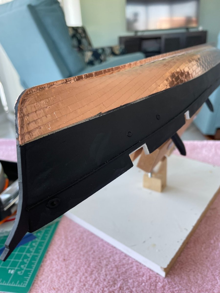
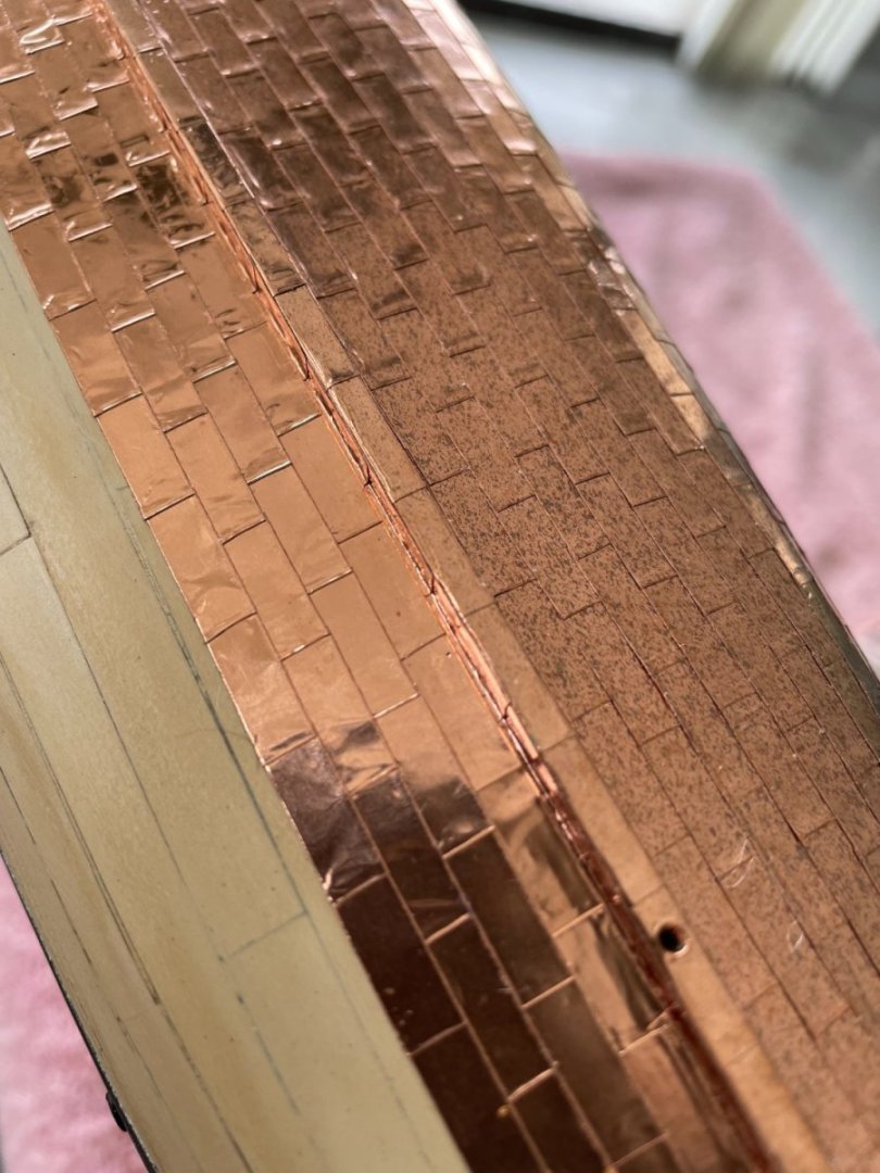
Coppering continuing: almost finished. Interesting and I'm not sure why this is happening but within a week of coppering the starboard side it started to tarnish. I've coppered this ship exactly the same way as I've done my other ships and have never seen this happen. In fact the copper plates on my Syren are still pretty much in the same condition as when they were installed. The only thing I can think of and I'm just guessing is that we are right across the street from the gulf and maybe it's the salt in the air.

- 144 replies
-
- 7
-
-
-
- Harriet Lane
- Model Shipways
- (and 1 more)
-
Thanks for following rcmdrvr, it's a nice little kit and I'm sure you will enjoy it.
- 144 replies
-
- 2
-
-
- Harriet Lane
- Model Shipways
- (and 1 more)
-
Thanks Jack, and the plating will cover a few dents in the hull as well. 😉
- 144 replies
-
- 2
-
-
- Harriet Lane
- Model Shipways
- (and 1 more)
-
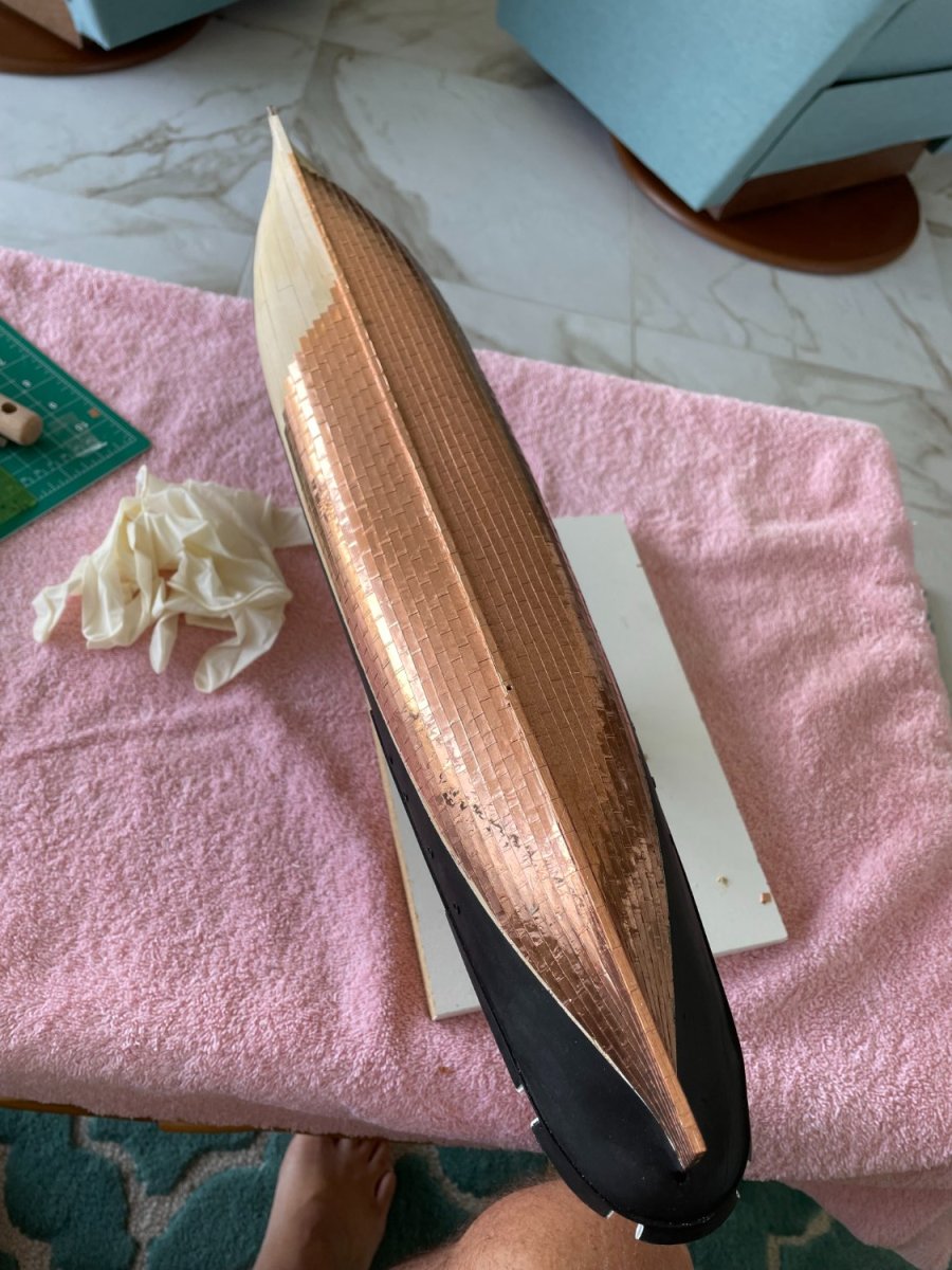
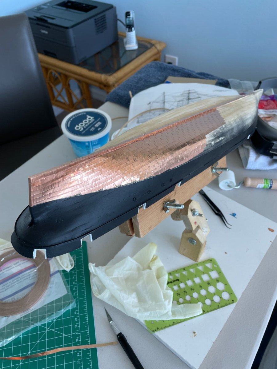
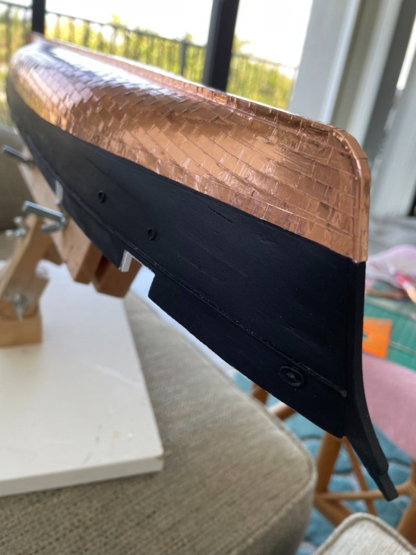
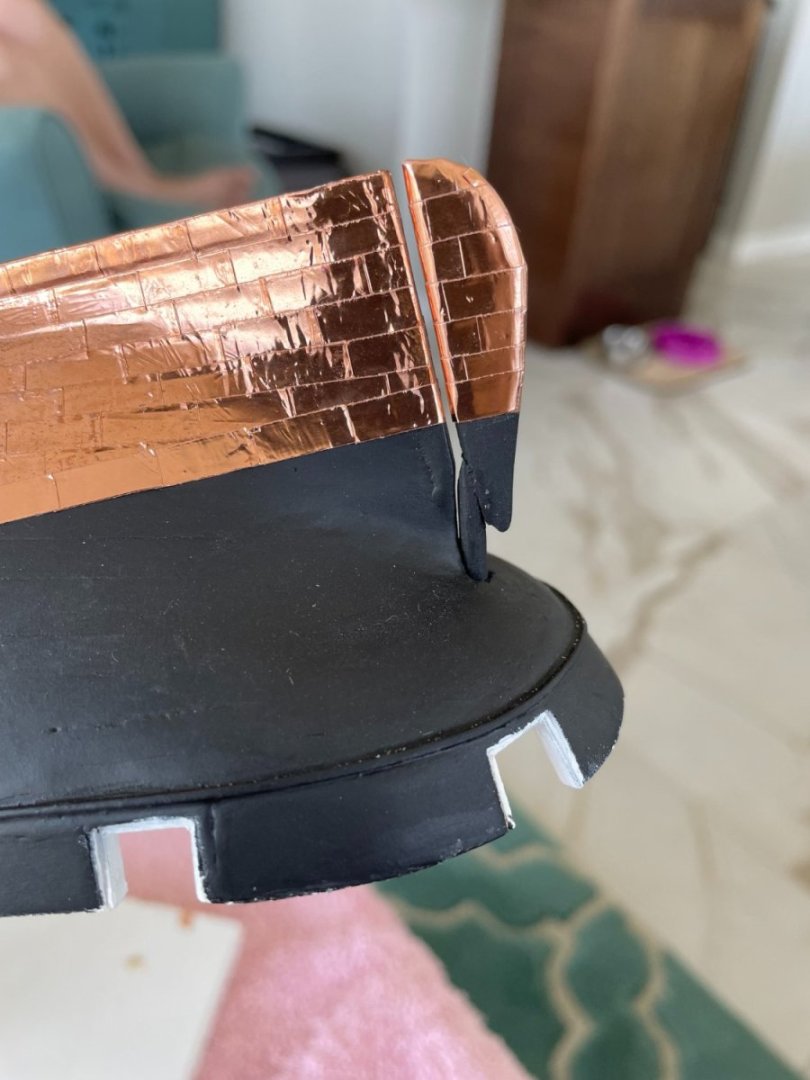
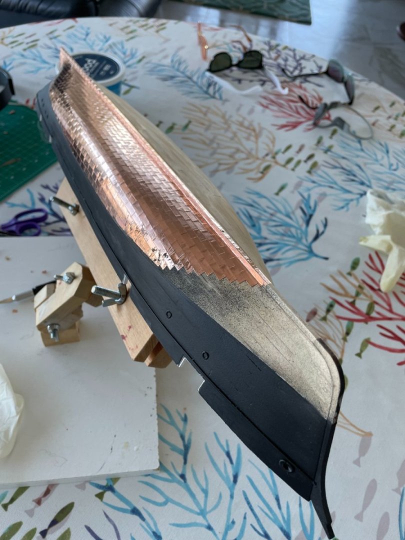
Underwater hull paint or not: To simulate the ships copper plated bottom it was recommended, per the instructions, to paint the bottom of the hull rather than actually copper plating it. This was recommended because it was thought that copper plates would look out of scale at 1:96. I had coppered the hull of my New York pilot boat the Phantom, which is the same scale (1:96) as this ship and IMO I thought that the plates looked appropriate. In any case I decided to copper the ship’s hull instead of painting it. Using the drawing shown below for reference I scaled the plates to be approximately 14” wide by 48” long. I had some 3/16” wide x 1.5mm thick adhesive backed copper tape which at 1:96 scale would make the plates 18” wide. Although the tape is a little wider than what’s shown on the drawing I didn’t think that I could cut it straight enough to make it the correct width. So for the plates I used a piece of tape 3/16” x ½” long (18” x 48”). At this scale, however, I did not show any plate fasteners. Port side plating. The over spray on the bottom of the hull is from some touch up I tried to the upper hull. This is why I don't like to spray paint, not patient enough sometimes. Thanks for all the likes and for following my build.


- 144 replies
-
- 5
-
-
- Harriet Lane
- Model Shipways
- (and 1 more)
-
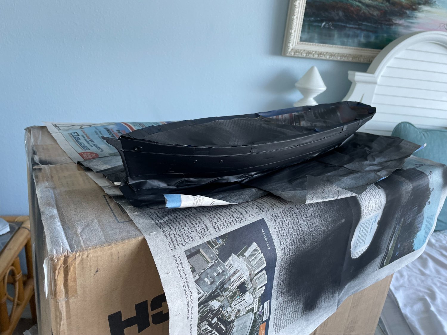
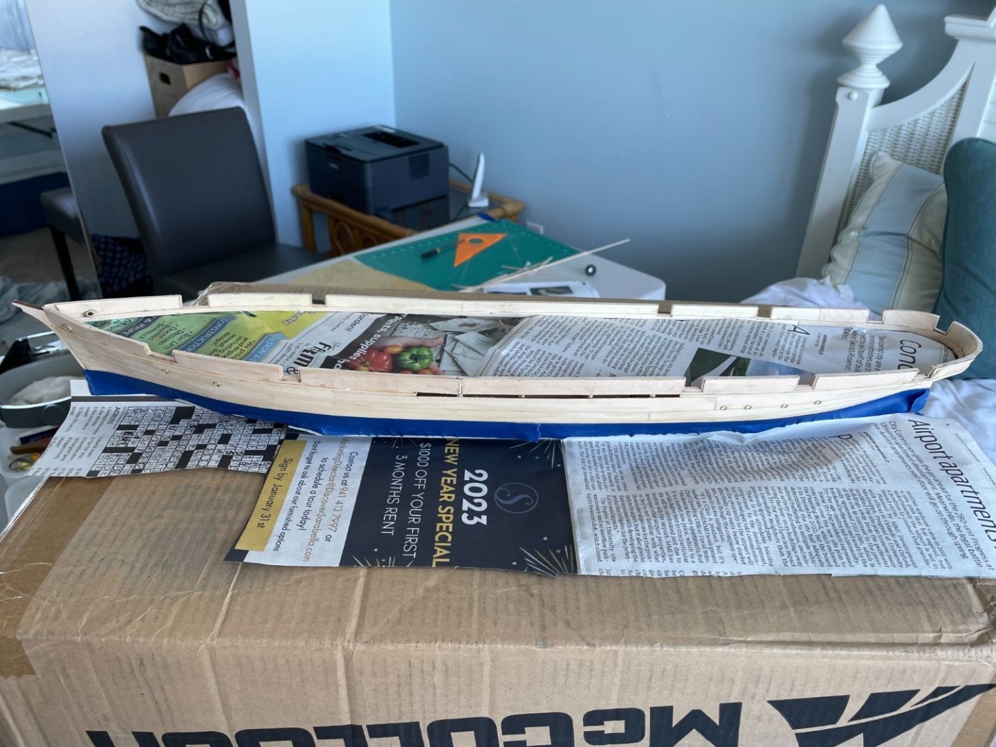
Topsides painting: I normally use a brush for all my painting but I decided I would try spray painting this time. I think the biggest reason I don’t like spray painting is because of all the taping and masking off you need to do. Taping the waterline. First coat, and no, just in case you're wondering, I did not spray it in the bedroom. Three coats later.


- 144 replies
-
- 8
-
-
- Harriet Lane
- Model Shipways
- (and 1 more)
-
Ron, the frig is full of them, come on down anytime. Good to be back and thanks for checking out my build.
- 144 replies
-
- 4
-
-
- Harriet Lane
- Model Shipways
- (and 1 more)
-
Alistair, very interesting method for aging the copper plates. I just might have to try it out on my current build. The one thing I'm not sure about however is which morning pee I should use, the 1AM or the 3AM or the 5AM or the 7AM.😉
- 16 replies
-
- 11
-

-
-
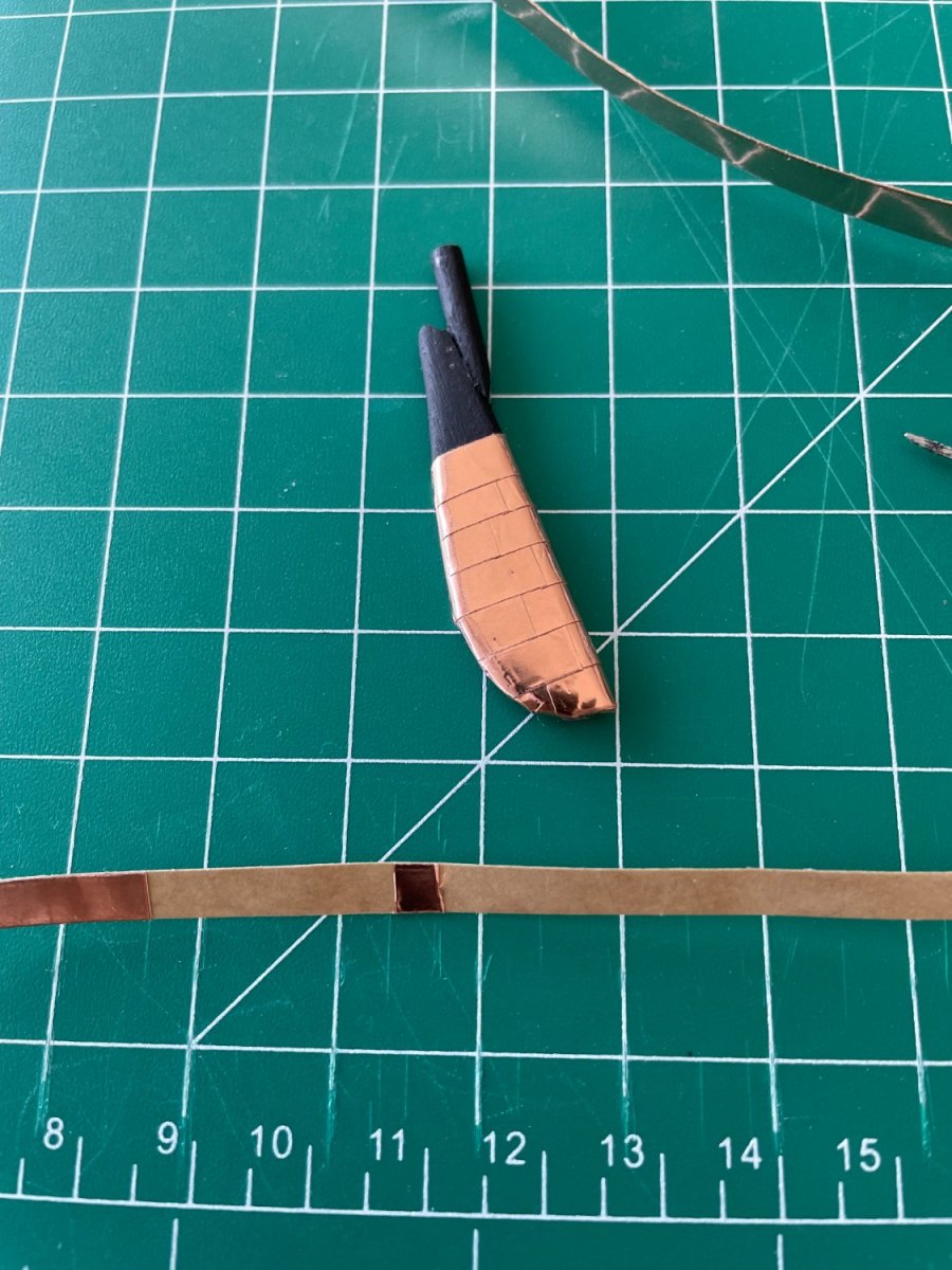
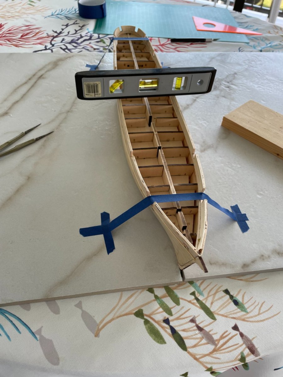
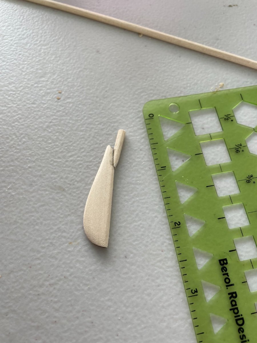
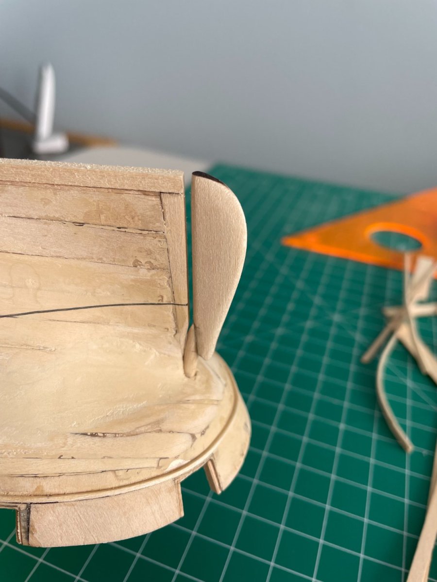
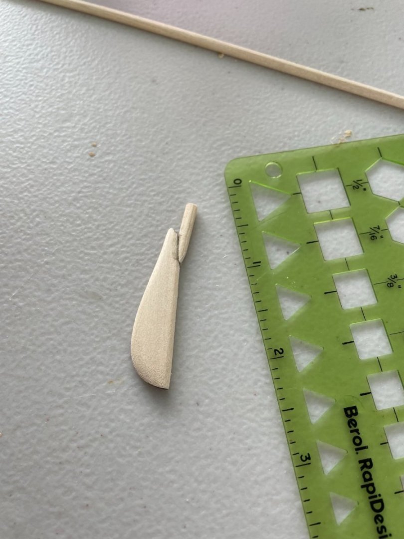
Drawing the waterline: In order to level the ship so I could draw the waterline, I improvised a little bit by clamping the ships keel in between two spare floor tiles I had. The hull was leveled and taped down and the waterline was marked out. Fortunately the dinning room table was also level. The rudder: The leading edge of the rudder was rounded per the instructions along with tapering its sides. The dowel for the rudders shaft was fitted and glued on. The hole in the hull was drilled and the rudder assemble was dry fitted. Thanks for all the likes and for following along.


- 144 replies
-
- 6
-
-
- Harriet Lane
- Model Shipways
- (and 1 more)
-
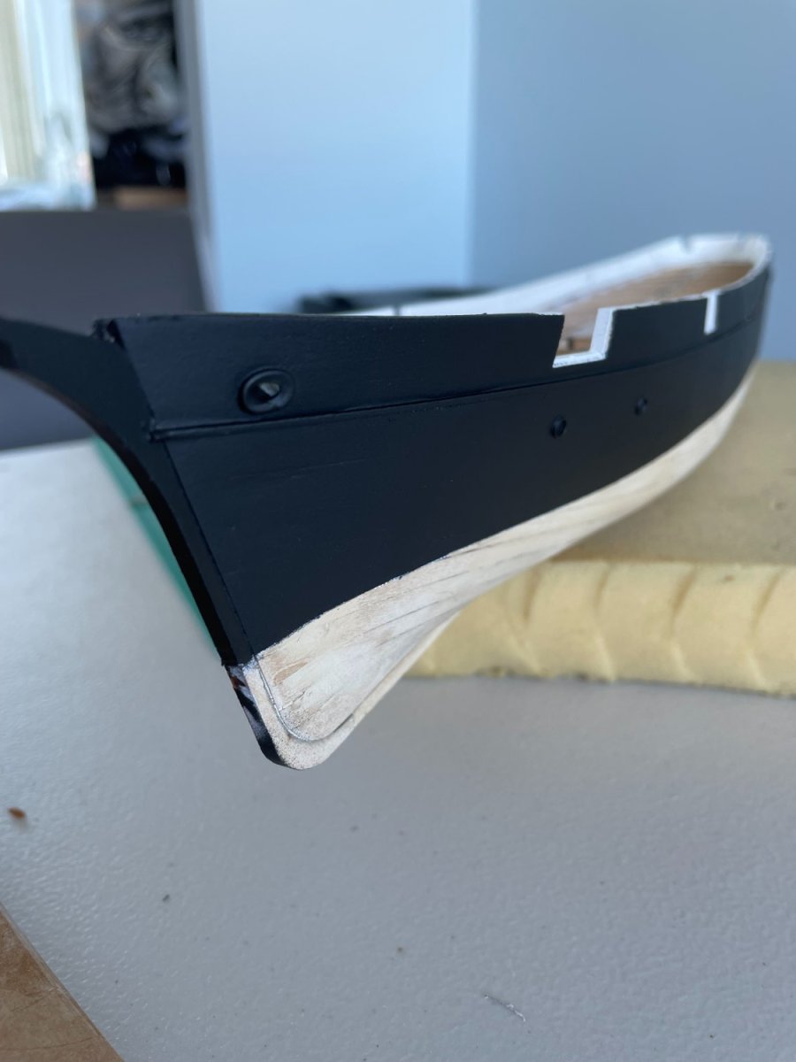
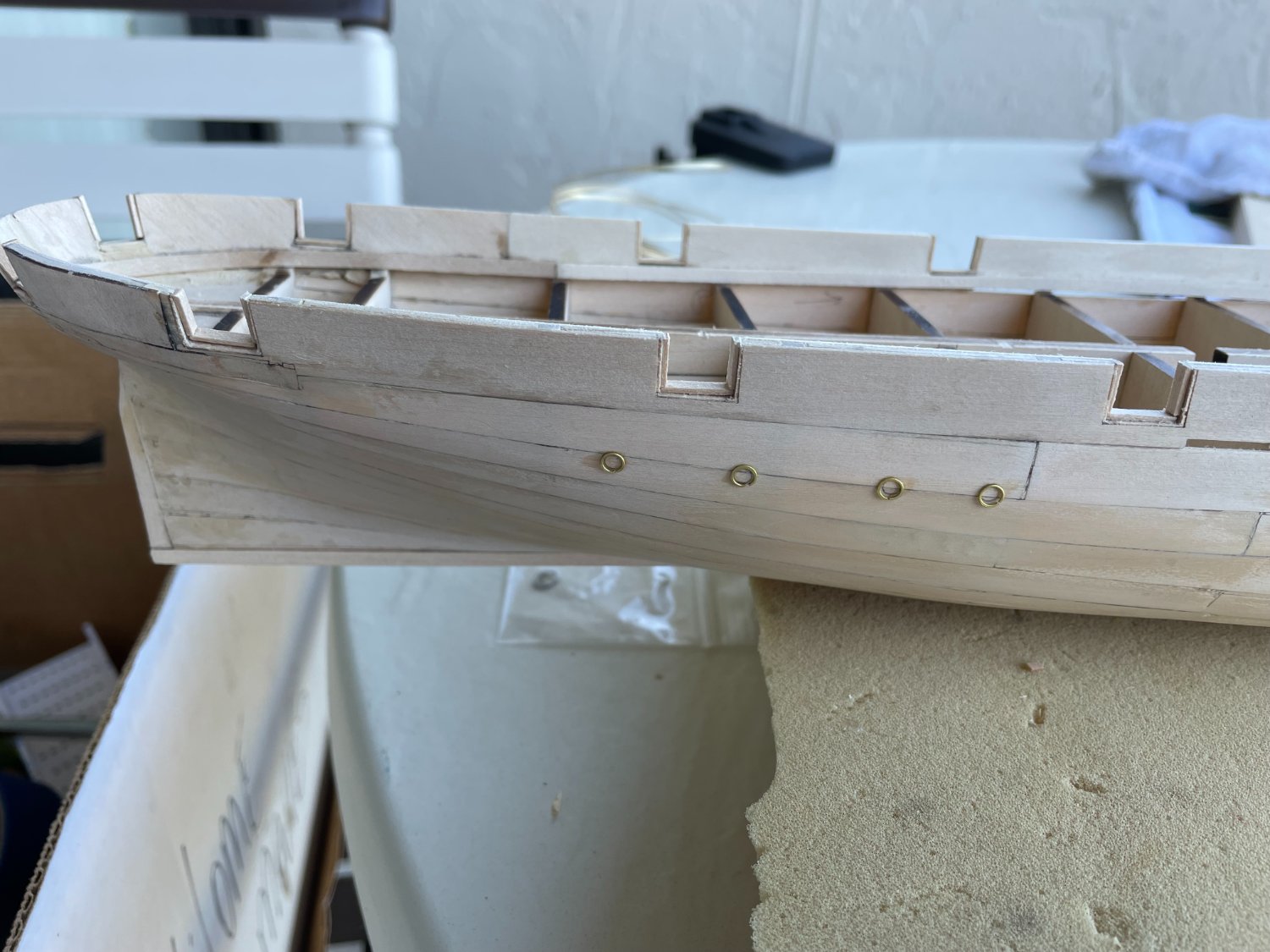
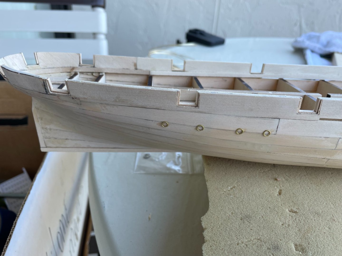
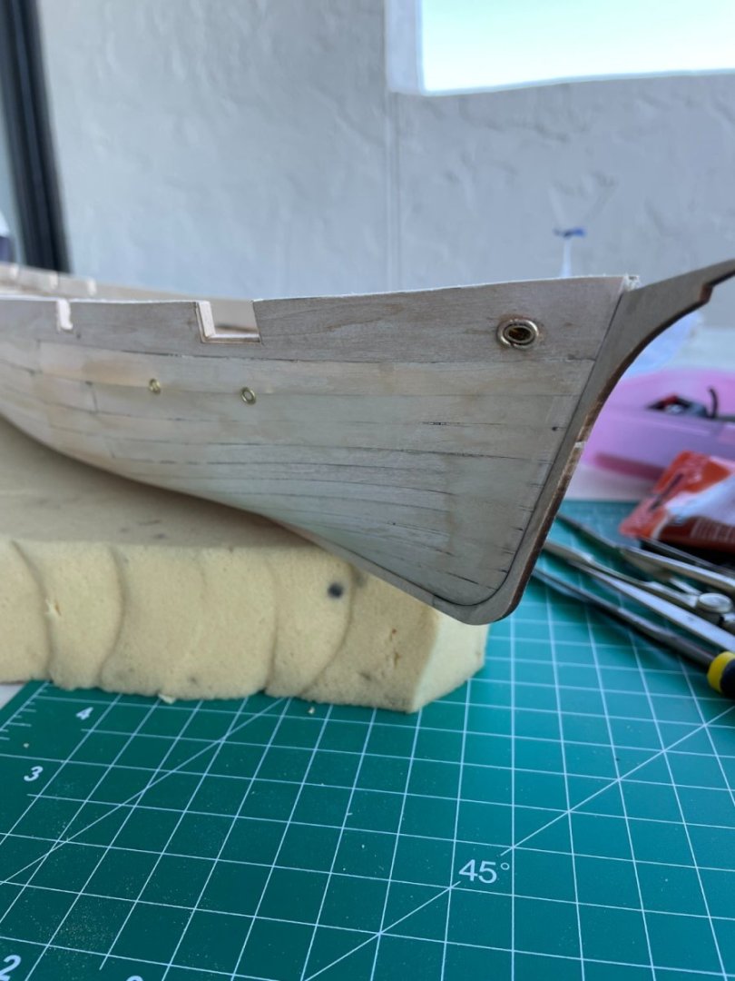
First I would like to thank everyone for all the likes. The gun ports were cut and lined as per an option in the instructions. The porthole locations were laid out using the templates provided and the brass rings were attached to the hull using some ac glue. The same brass ring used for the portholes was supposed to be used for the hawse holes just flattened out into an oval shape. After doing this I just didn’t think the ring was the appropriate size. I used some brass wire to form an oval for the outer hawse hole and went a little farther and cut and filed a piece of brass tubing to line the hole through the hull. The brass tube was eventually filed down flush with the inner bulwark. Since the hull will be painted I just used some wood filler to fill the gaps around the wire and tubing.


- 144 replies
-
- 8
-
-
- Harriet Lane
- Model Shipways
- (and 1 more)
-
Nice job on the sills and lintels Bob. Stern is lookin good. I remember the inboard side of the bulwarks were a challenge to sand. Hope you're all recovered from the cold/bronchitis and good luck with quitting smoking.
-
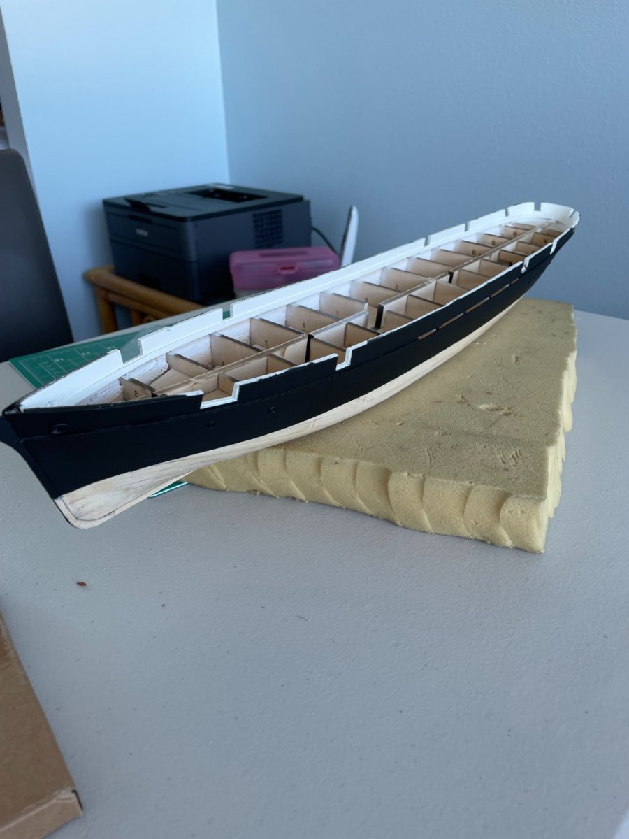
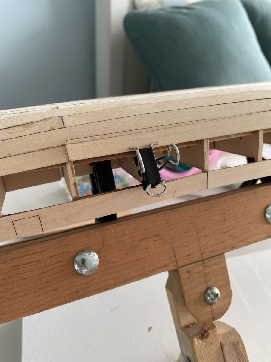
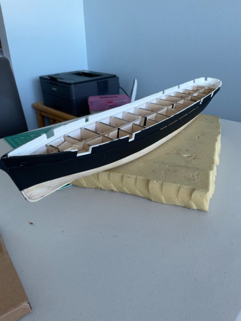
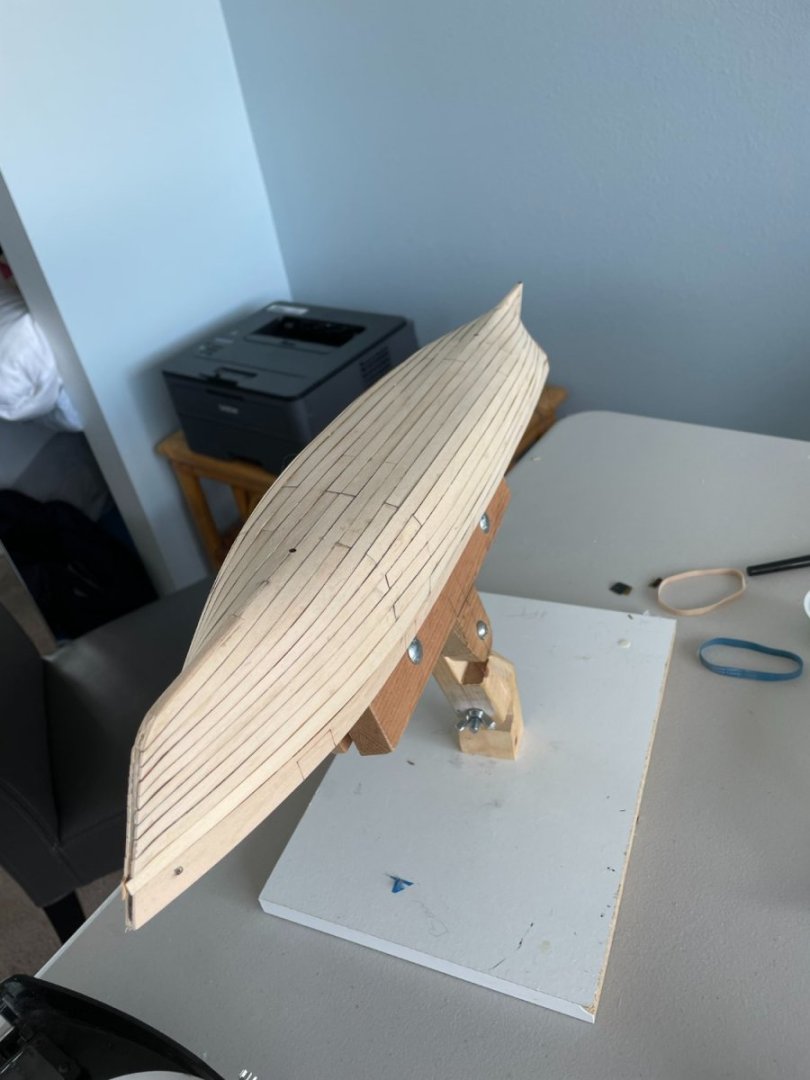
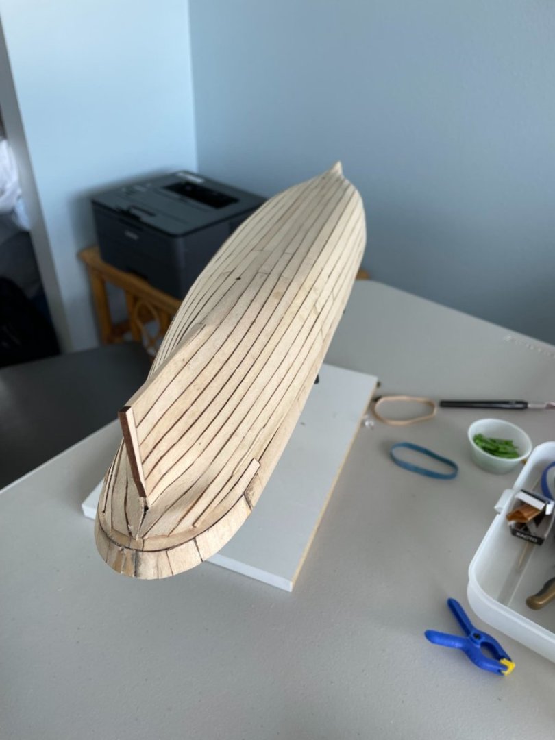
Finished sanding the hull without having to use too much filler. After the sanding was complete the outer keel, stem and stern post were glued on. . Inner bulwark planking: Gluing the inner bulwark planking was pretty straight forward.


- 144 replies
-
- 7
-
-
- Harriet Lane
- Model Shipways
- (and 1 more)
-
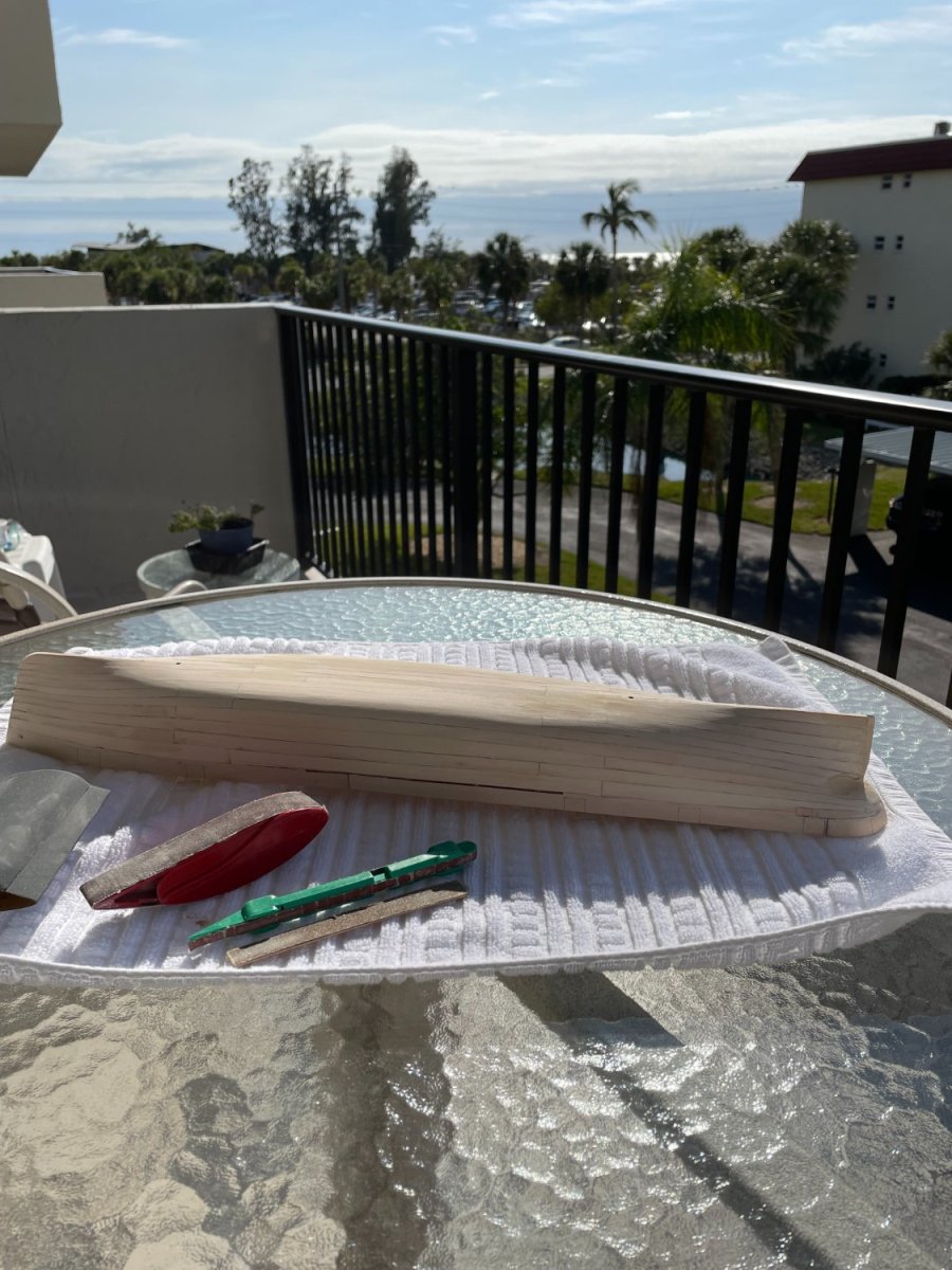
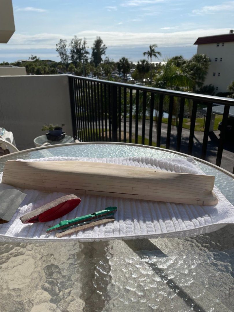
Thanks druxey and thanks for all the likes. No workshop but at least I have a nice view while sanding.
- 144 replies
-
- 7
-
-
- Harriet Lane
- Model Shipways
- (and 1 more)
-
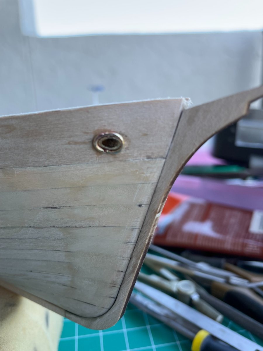
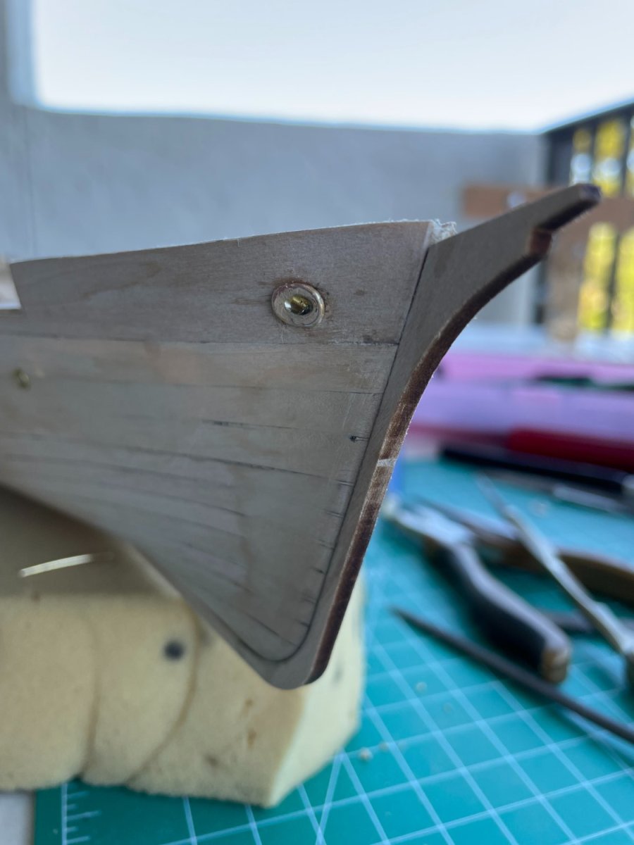
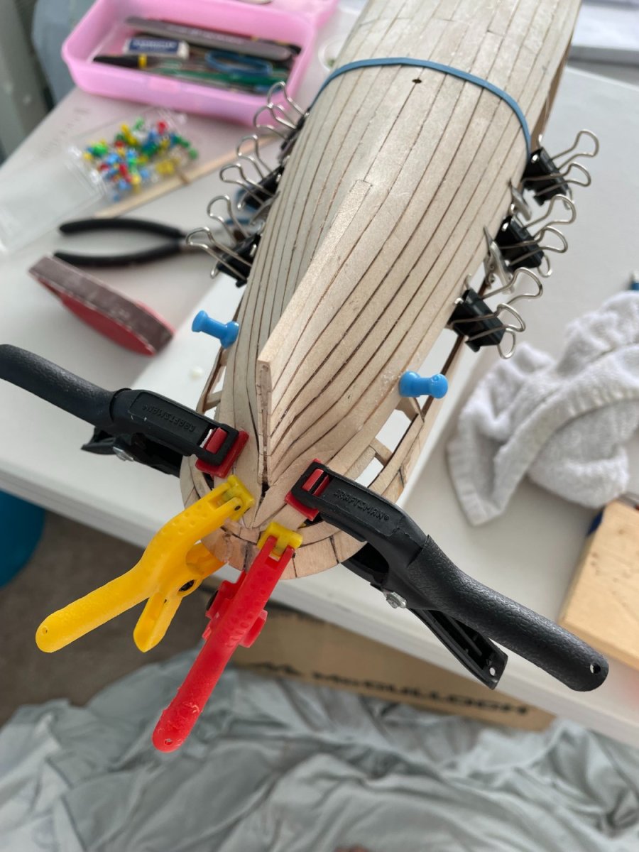
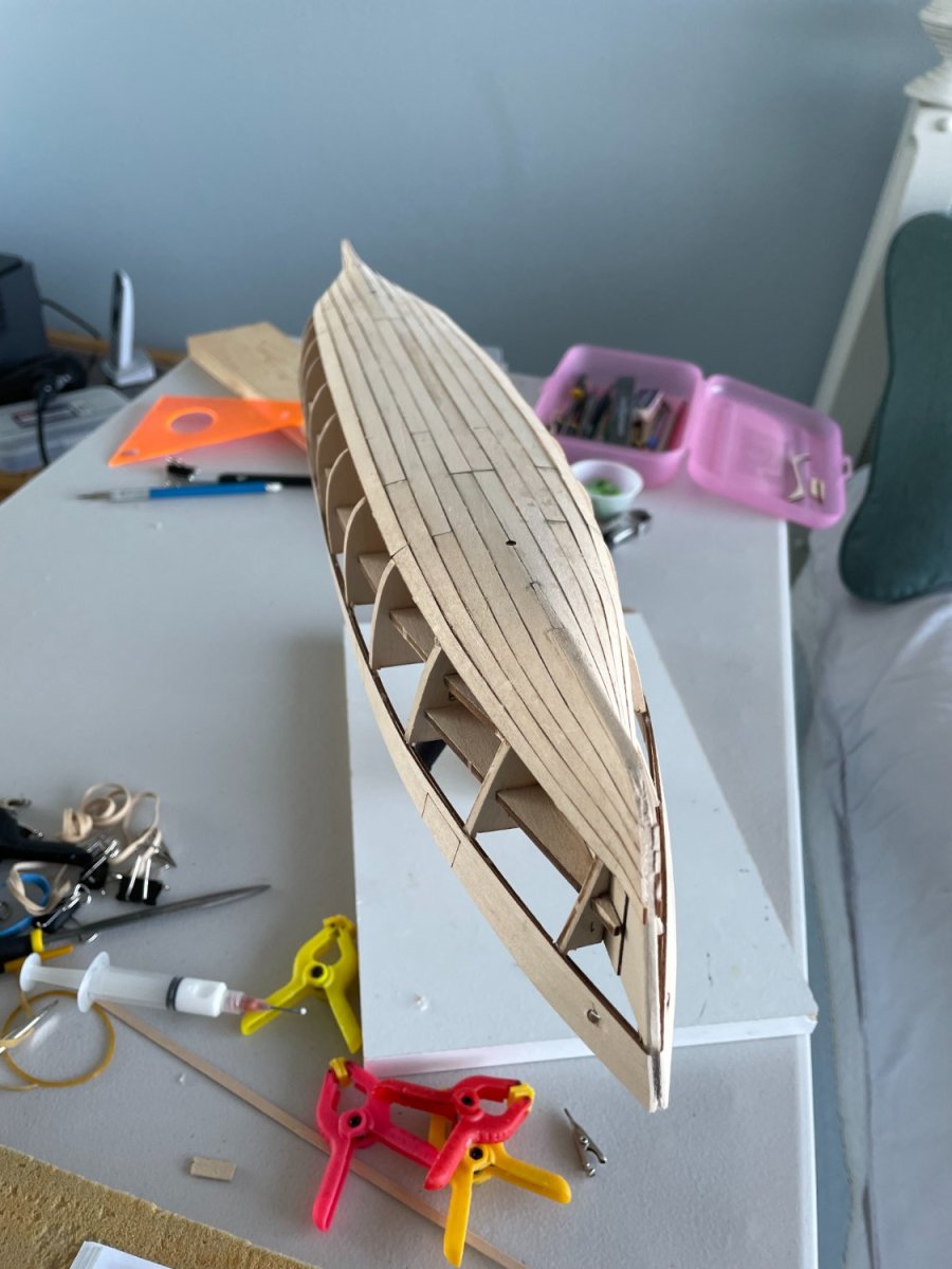
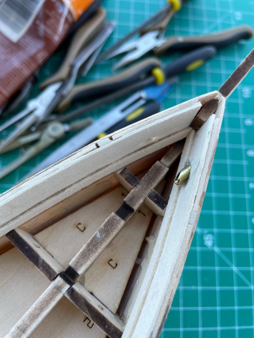
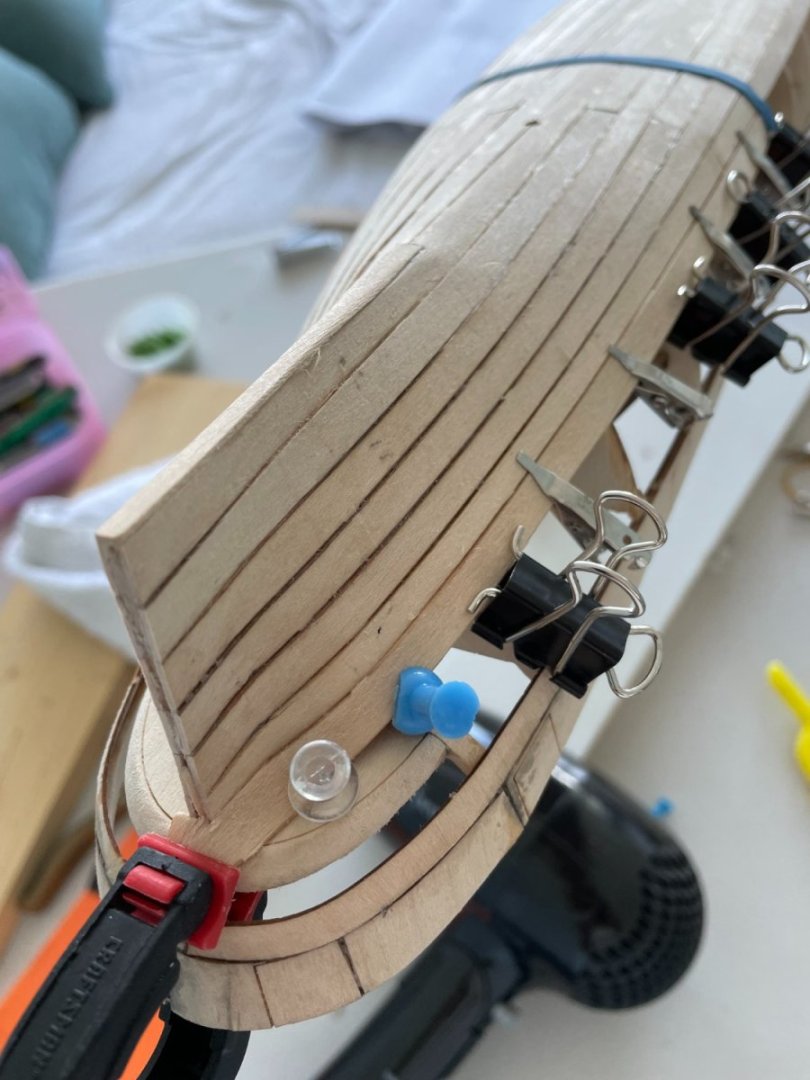
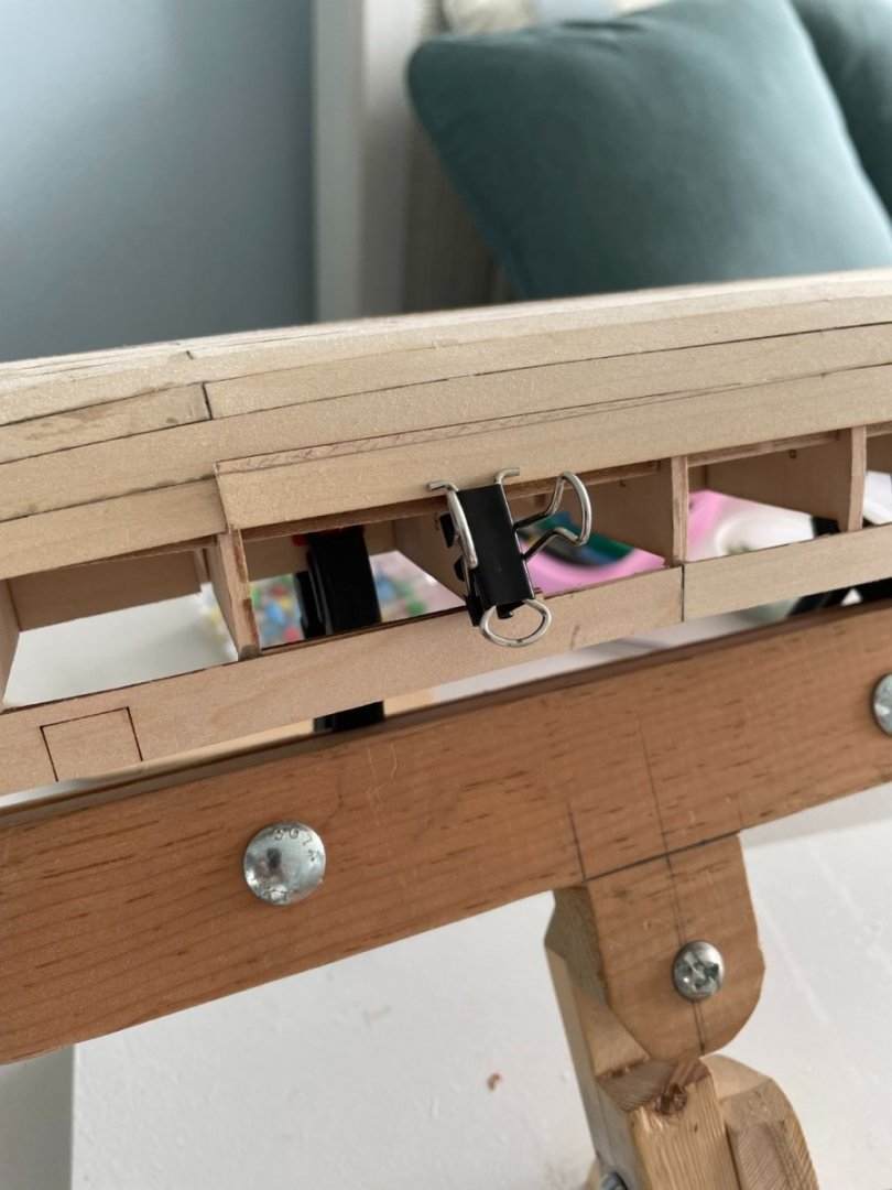
Planking around the stern knuckle proved to be interesting with some creative clamping. I found I had to trim (shaded area on plank) two of the central planks in order to maintain an even run of the planking. Completed planking

- 144 replies
-
- 6
-
-
- Harriet Lane
- Model Shipways
- (and 1 more)
-
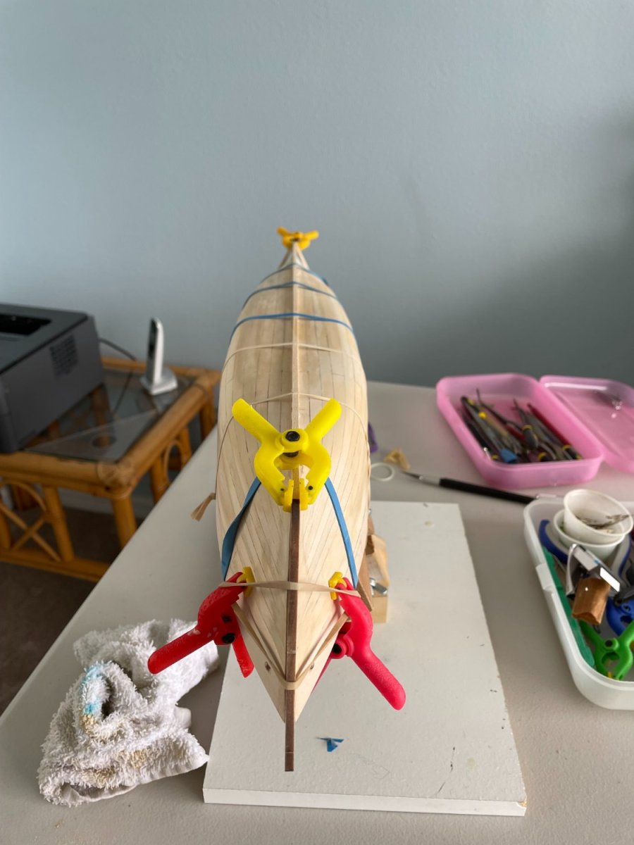
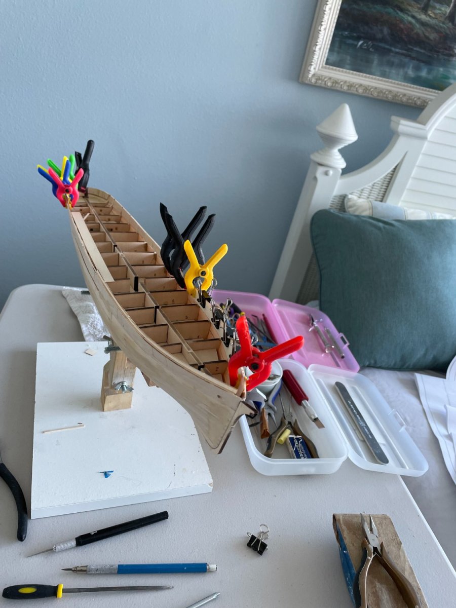
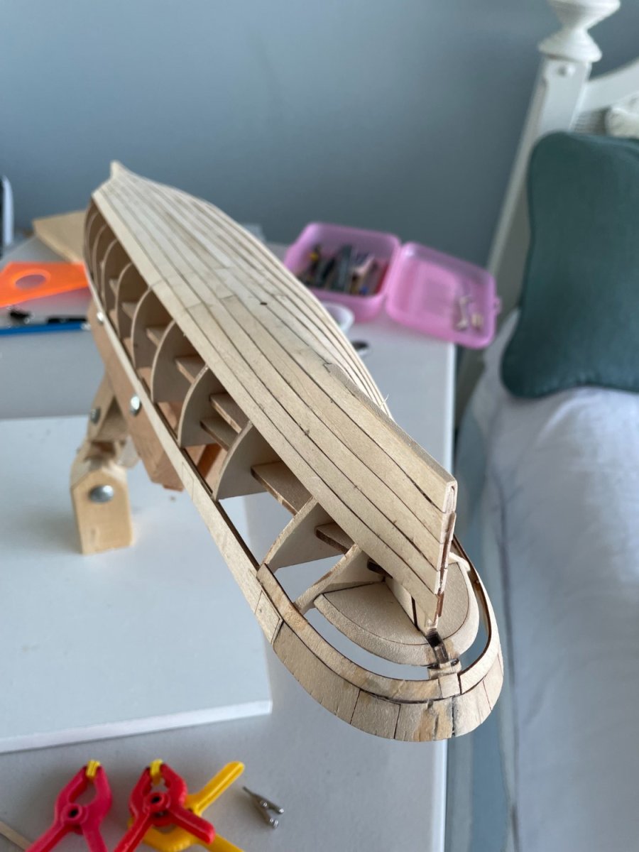
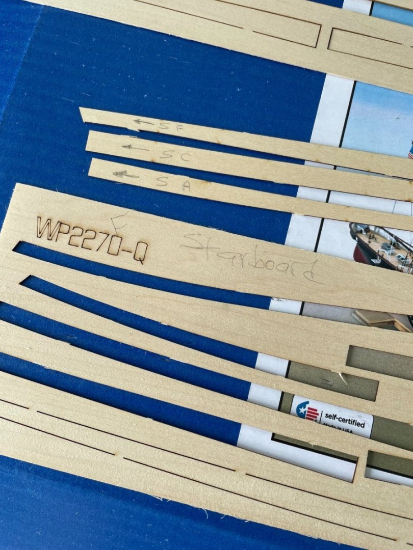
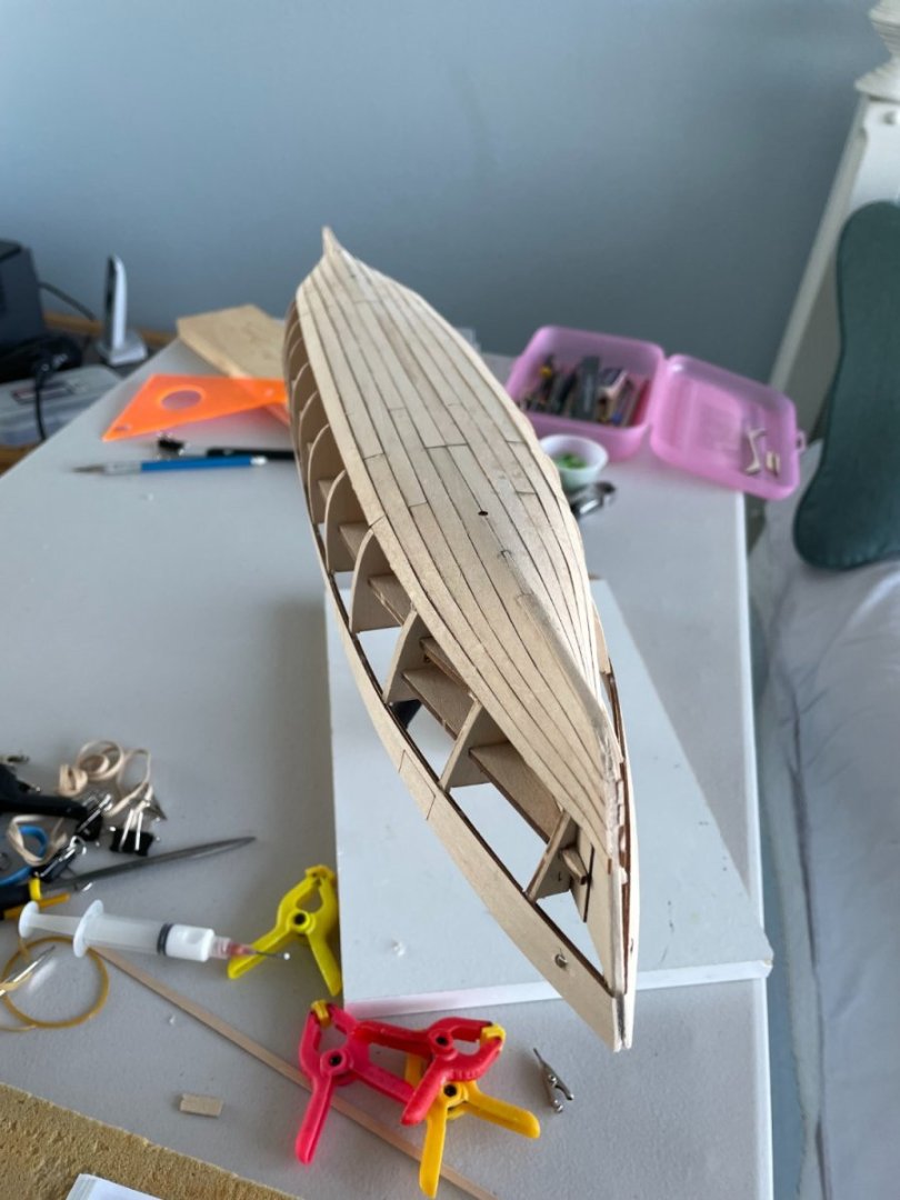
Used the first two sheets of planking which did approximately half the hull. All the port fore pieces had to be sanded down to match the width of the starboard side. All of the port and starboard center and aft pieces were the same size so no sanding was required for them. I also found it very helpful to label the back of each piece to avoid confusion as to what side and in what direction the planks go after they are removed from the sheet.

- 144 replies
-
- 3
-
-
- Harriet Lane
- Model Shipways
- (and 1 more)