HOLIDAY DONATION DRIVE - SUPPORT MSW - DO YOUR PART TO KEEP THIS GREAT FORUM GOING! (Only 20 donations so far - C'mon guys!)
×


_SalD_
-
Posts
828 -
Joined
-
Last visited
Content Type
Profiles
Forums
Gallery
Events
Everything posted by _SalD_
-
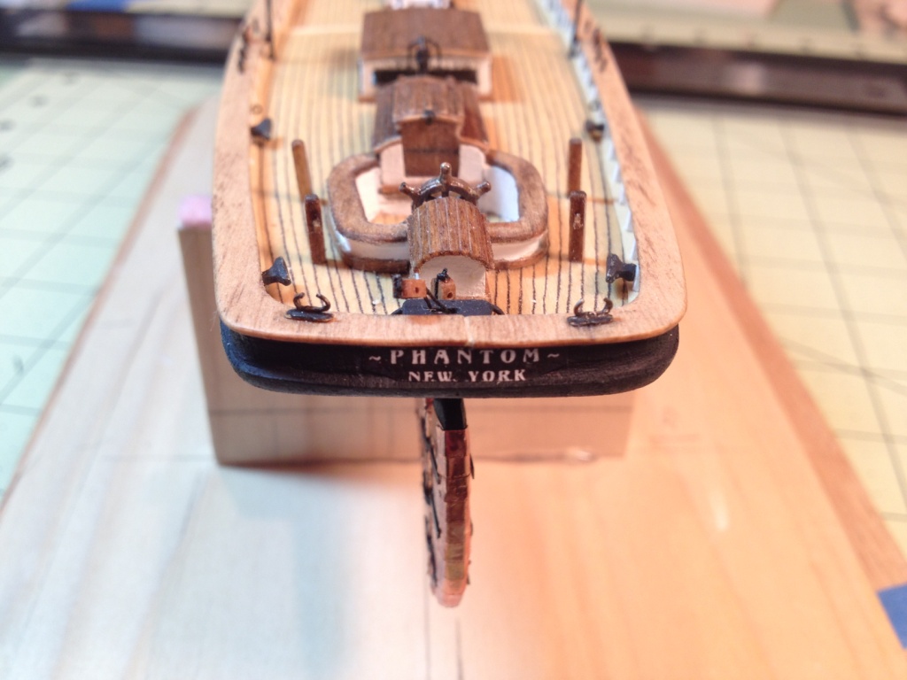
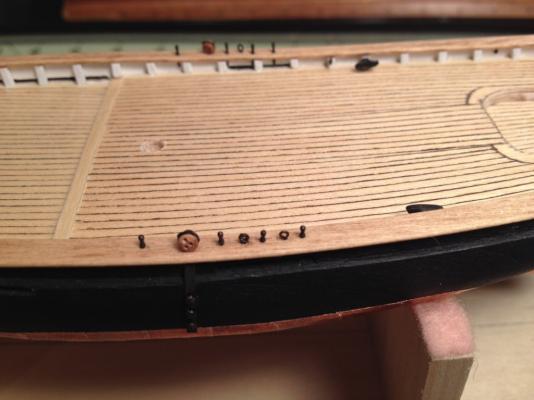
 Max, You give me way too much credit for my artist abilities. I only wish I could have hand painted those names on. A stencil is a good idea that I hadn't thought of, although it would be kind of tough cutting out those little letters. Alas, all I did was print out the names on plain white printer paper with a black background. The bow letters have a font size of 8 and the stern letters are 5 and 4. I then cut the names out to fit the step area and after positioning them I painted over them with a diluted (50/50) mixture of white glue and water. You can't see it in the pictures but if you get real close you can see the paper. You need to darken the edges too so you can't see the white edge on the paper. One thing I did learn while doing this is that there is no white ink in printers.
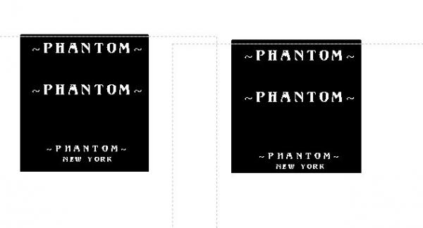
- 139 replies
-
- 1
-

-
- phantom
- model shipways
- (and 1 more)
-
Chris and Russ thanks for the kind words.
-
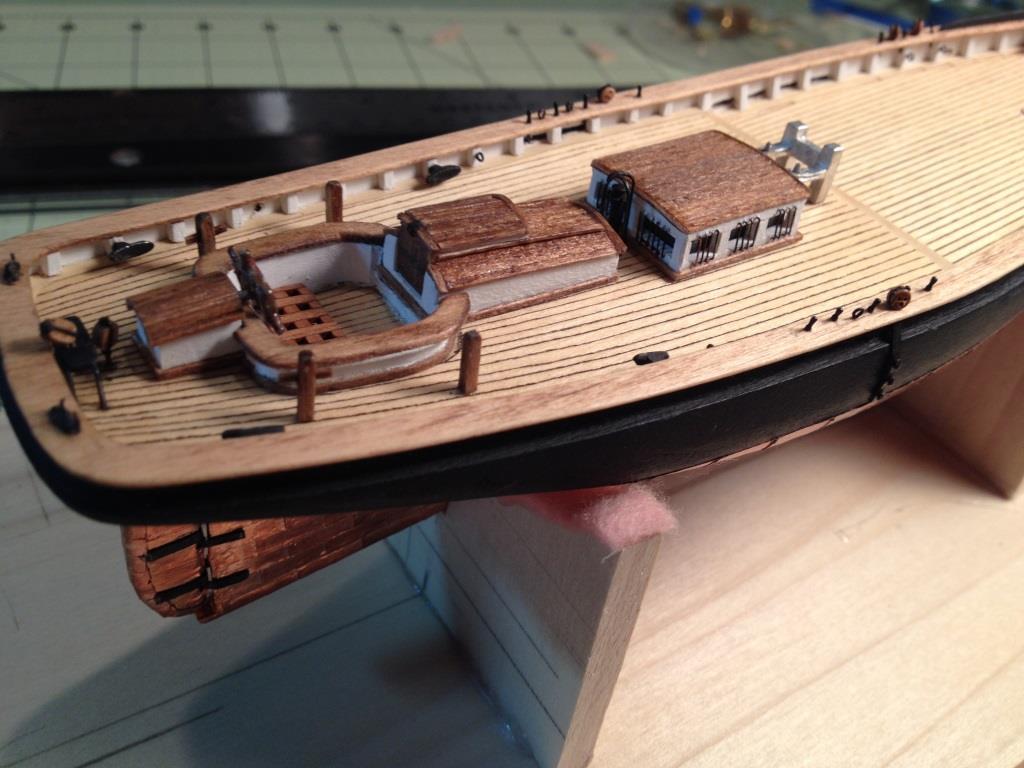
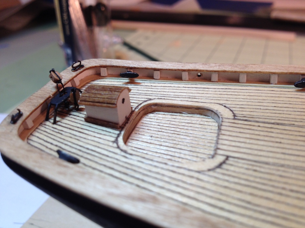
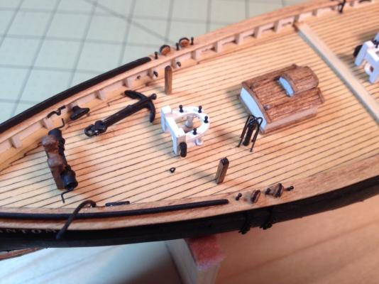
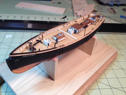
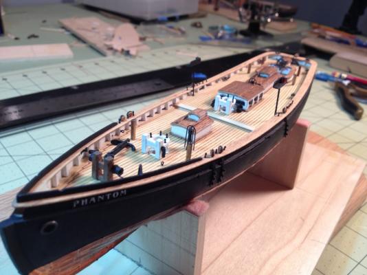
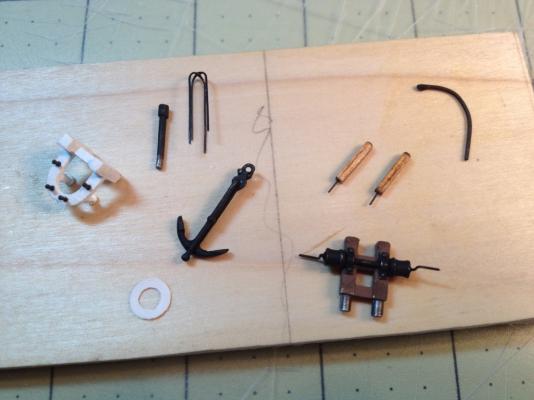
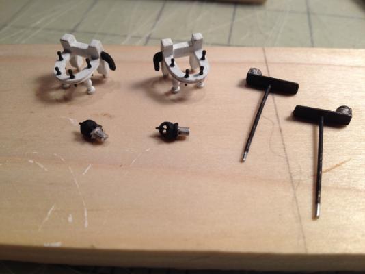
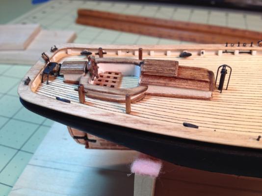
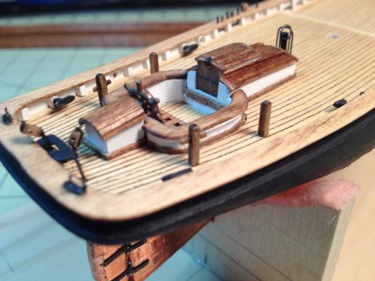
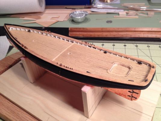
Completed the fore deck fixtures. I assembled the fore deck companionway, painted the vent pipe and made the wire guard, painted the anchor, made two more bollards, made the davit from the wire of a paper clip, installed handles (used 28 gage wire) on the winch bits and then painted it, and made another mast coat for the fore mast similar to the one made for the main mast. The positions of all these pieces were located on the fore deck from the plans and the appropriate size holes were drilled in the deck. All the parts were then glued in place. Note that there is another eye bolt that appears to be needed near the fore fife rail that is not mentioned in the practicum until later in the rigging chapters. According to the Chuck’s practicum I am now officially half way complete with my ship. I must admit I do feel a sense of accomplished in the progress I've made to this point. I've enjoyed each task preformed so far, although some less than others. Coppering the hull is pretty far down on the list. I would also like to take this time to thank Mr. Chuck Passaro for his excellent practicum. If it wasn't for his guidance through his practicum I would have never been able to complete all this. It’s always easier to enhance things that someone has already designed. I hope that the second half of this build goes as well (knock on wood) as the first. With Chuck’s guide I’m sure it will. Since I’m thanking people; I would like to thank everyone for their words of encouragement and help and for all the ‘likes’ so far.

- 139 replies
-
- 8
-
-
- phantom
- model shipways
- (and 1 more)
-
Max, The deck fixtures look terrific. I like the way you need your bars in the skylight window. I also like that jig for sanding the wood down, I'll be borrowing that idea.
-
Anchor Question
_SalD_ replied to _SalD_'s topic in Discussion for a Ship's Deck Furniture, Guns, boats and other Fittings
Kester, Thanks for all the information. It makes sense now. Sometimes I'm a little slow but I usually catch on after a while. -
Anchor Question
_SalD_ replied to _SalD_'s topic in Discussion for a Ship's Deck Furniture, Guns, boats and other Fittings
Kurt, Thanks. I looked at that very picture a dozen times and it never dawned on me (pointing two fingers at head and pulling trigger). -
Anchor Question
_SalD_ replied to _SalD_'s topic in Discussion for a Ship's Deck Furniture, Guns, boats and other Fittings
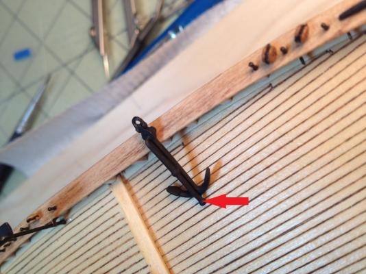
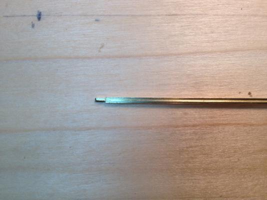
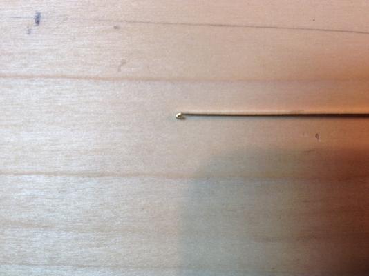
Hi Jud, If you look close at the picture you can see that it's part of the anchor and not leftover from the casting. It runs the full length of the anchor. -
The anchor that came with my kit, Model Shipways ‘Phantom’, has what appears to be a bar or pipe attached to it. See picture with arrow pointing to bar. I tried to find out what it was by googling ‘anchor’ but had no luck. Not knowing what it is or what it’s called sort of limited my search ability. I also searched this forum with no luck either. In a roundabout way of asking, I would like to know what it’s called, if it has a name, and what its purpose is. Thanks
-
Thanks Russ, sometimes I even impress myself.
-
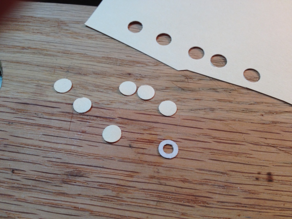
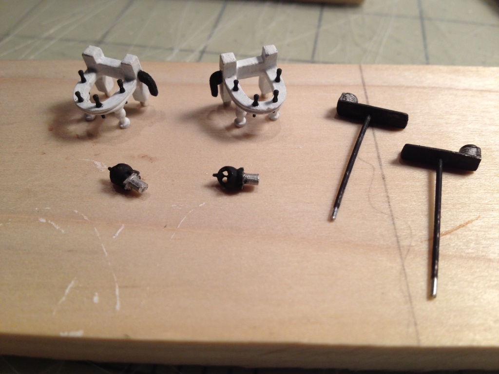
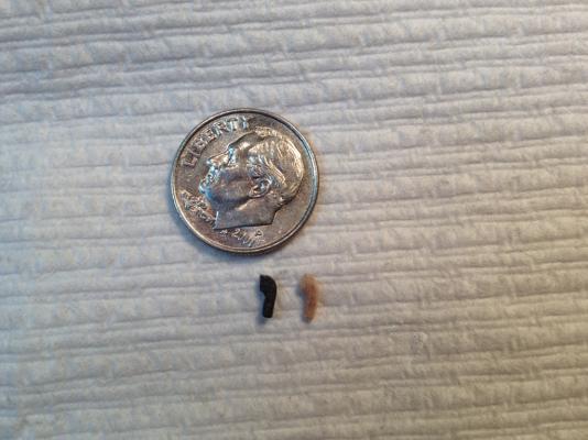
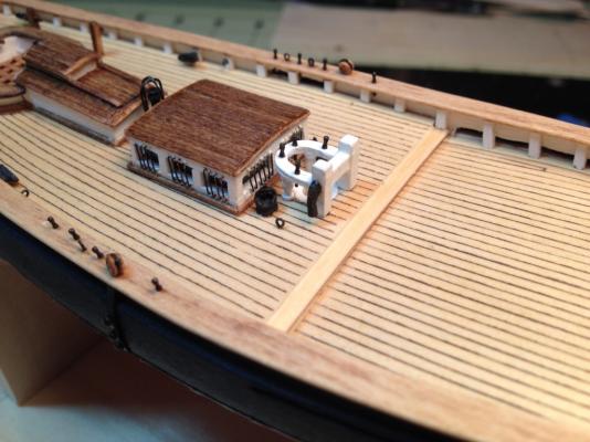
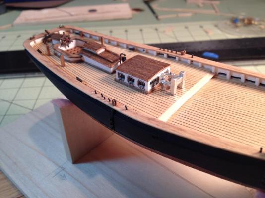
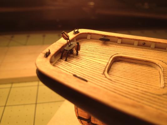
I thought that after building the companion way and skylight, the fife rail would be a piece of cake. Clean up the castings, slap a few coats of paint on it and glue it to the deck. Wrong! Now you need to make a tiny cleat. I wasn't quite sure what to make the cleat out of so I tried a piece of the 1/32” thick sheet. That didn't work too well because the piece broke apart too easily. I ended up using a piece of the 1/8” square stock. I drew the profile of the cleat on the side of the wood and started filing. Using needle files and an emery board I whittled away until all I had left was the cleat. Sort of like making a toothpick from a 12” diameter log. I decided to do both fife rails at the same time so I make two cleats. Assembling the fife rail was simple enough; the two stanchions were glued on, painted it white, installed the belaying pins, that I had previously blackened, and glued on the cleat. The one modification I made was to remove the pins on the bottom of the stanchions that are supposed to be fastened into the deck. I thought that the large pins on the other two legs of the rail would be sufficient to hold it in place and that drilling two holes in the deck would be easier to position than four. The pumps were painted black and the navigation light stands were made just as described in Chuck’s practicum. My jumbo paper clips seemed a bit thick so I used a ‘Size 1’ paper clip. The lights in the picture are not finished and still need another coat of paint and have the handle attached. The mast coat, I discovered, could easily be made using my three-hole punch. I punched out some holes of the manila folder, used my circle template to draw the inner hole for the mast and cut it out with my x-acto knife. Once all the parts were ready; first the mast coat was glued to the deck using the mast dowel to get its correct position. Then I glued the fife rail into the holes that I had previously drilled when I installed the skylight. The holes for the pumps were drilled a bit off from where they show on the plans, in a position that looked good and was easy to drill. The last thing I installed was an eye bolt on the starboard side of the fife rail. This eye bolt is shown on the drawings and is mentioned in the practicum later on when Chuck describes rigging the Main Gaff.

- 139 replies
-
- 3
-
-
- phantom
- model shipways
- (and 1 more)
-
Robert, thanks for looking at my build and the kind comments. Marty, thanks for following my build. It’s a nice first build that you can do as much or as little as you like. As far as the copper plates, I have some that are coming up too. I just press them back down and try not to handle the boat below the waterline too much. I haven’t sealed mine and I probably won’t at this point, whether you do or not is more a personal preference. I don't know if sealing would prevent them from coming up. I’m planning to wait until the ship is complete and then fix the plates one last time and then clean them up. Joe, thanks for taking the time to go through my build and I’m glad you like it. By the way, I didn't think mechanical designers ever retired, they just draw Iso’s forever? I'd like to thank everyone for there 'Likes' also.
-
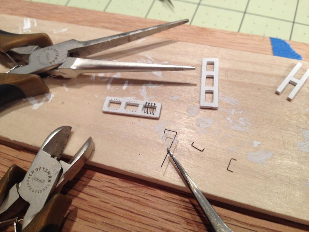
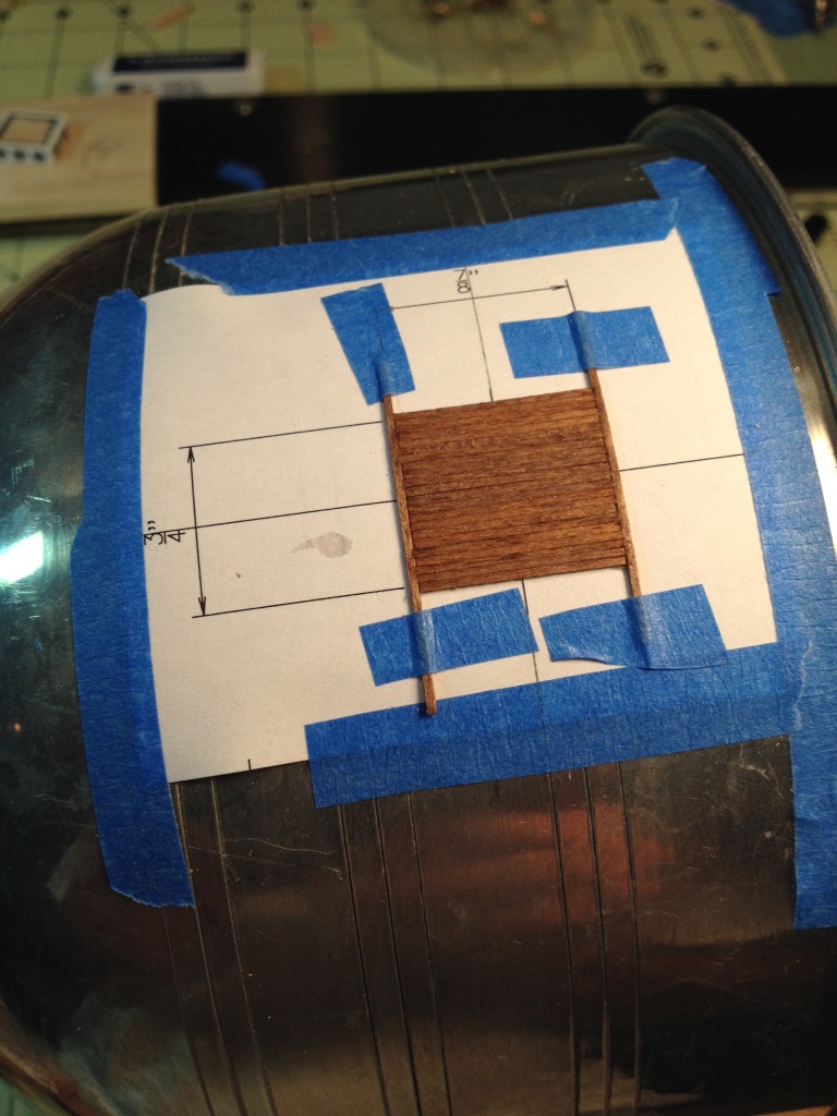
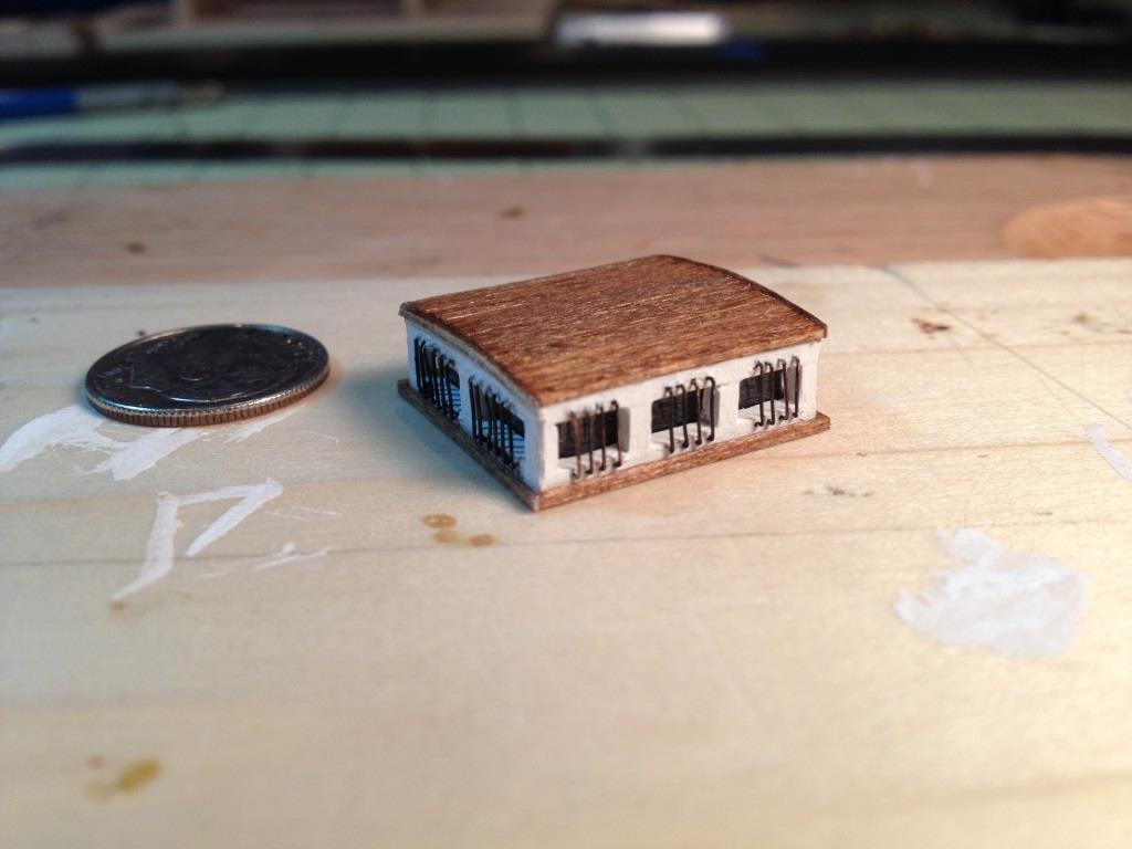
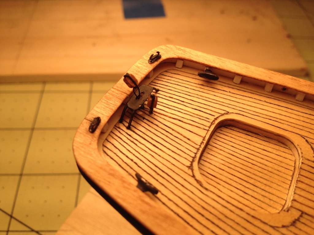
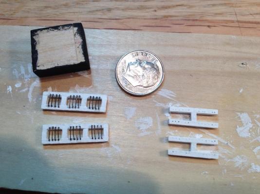
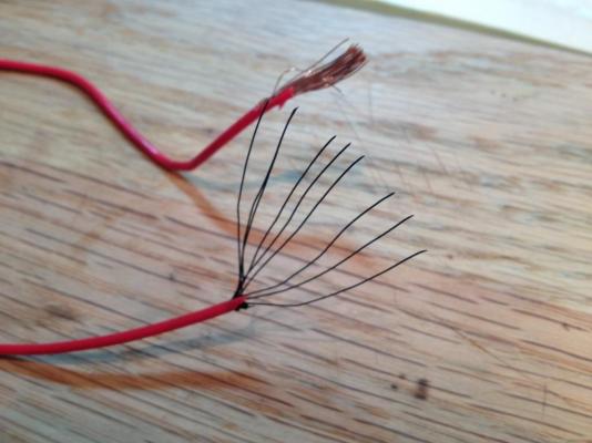
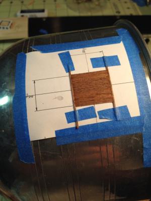
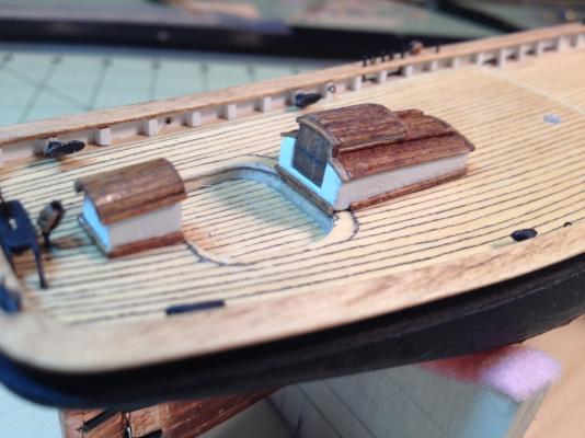
Well it took some time and the jury is still out whether all the time I put into building the skylight was worth it, but I finally finished it. I took Chuck’s advice making separate window frames mounted on a small block to make up the skylight. I used 1/16” square stock for my frames, so I made the block 1/8” smaller than the dimensions of the skylight taken from the plans. I’d like to mention here that in hind sight I should NOT have used the length dimension of the skylight from the plans. As it turned out, the skylight, using the dimension from the plans, would not have fit between the stove pipe and fife rail of the aft mast whose hole I had already drilled in the deck. Fortunately, I discovered this before I assembled all the pieces. I ended up shortening the block and sanding down the end window jambs of the three pane frame to make it fit and it’s still pretty tight. I then decided to try and put the bars on the windows. First I drew guide lines on the frames above and below the windows. I then marked off the location of each bar along the guide lines which, for my windows ended up being 1 mm apart. I then drilled a hole at each mark and then erased the guide lines. I had already picked the wire I was going to use so I knew what size hole to make. For the bars I thought that the 28 gage wire that comes with the kit would be too thick. Since the Admiral has tightened the purse strings on buying any additional material for this build ( I can’t imagine why) I looked for something I already had. What I found, and used, was the copper wire from some 16/2 speaker wire I had used to wire the surround sound in the family room. I striped a piece of the sheathing, blackened the wire and had the material for the bars. I’m guessing the individual strands are around 30 gage. My next problem was to find something that I could make the bars with so that they would be all same size. After trying a few methods that didn’t work too well, what I stumbled upon was to use my needle nose pliers. As can be seen in the photo below, I placed a pencil mark at the position along one of the jaws that equaled the length of bar I needed. I then clamped the wire in the jaws and bent the wire down to form a square ‘U’ shape. I then trimmed the wire as required and inserted the ends into the holes. Trying to impress my daughter, I showed her what I was doing and unimpressed she told me that I have way too much time on my hands (next life, no kids ). I installed all the bars prior to gluing them in. Before gluing them I threaded one of the unblackened wires between the window frame and bars so as to keep them slightly off the frame. After all that, I assembled the skylight gluing the frames to the small block. Before gluing the frames on however I placed a piece of transparent tape around the block as in the practicum. For the roof I tried a different procedure than I used for the wheelhouse and cockpit companionway. For those two items I installed the roof pieces directly on the block one at a time, for the skylight I tried making the roof independently and then installing it in one piece. I pre-bent the edge pieces first by soaking them and taping them to an ice bucket with the appropriate radius. I then installed the roof members in between them, gluing them in place as I went. Once the entire roof was made I glued it on to the skylight. To finish I installed the base board trim around the bottom. Was it worth putting the bars on? I think so. It took a while but in the end I think it was worth the effort. Maybe I should have made them a little smaller. The fife rail is only in temporarily to make sure it all fit.


- 139 replies
-
- 1
-
-
- phantom
- model shipways
- (and 1 more)
-
Max, Thanks for stopping by and I'm glad you like my build so far, and please, free feel to copy anything you like. As far as me being a genius, I keep telling the admiral that but for some reason she doesn't buy it.
-
Scott, I'm glad you like it. Thanks for following along,
-
Max, I'm glad your chain plates came out better. The rear chain plate does come very close to the copper plating. If you check the ship's elevation drawing you'll notice that it almost touches the copper. Your Phantom looks great, good luck with the rest of the build.
-
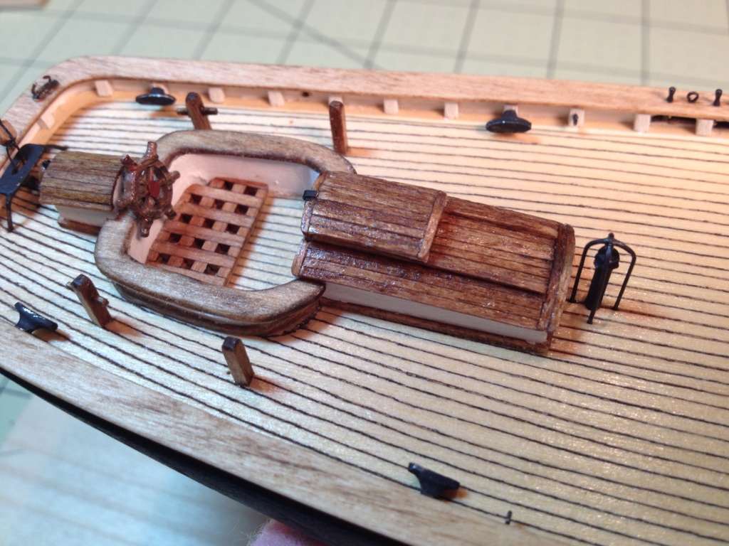
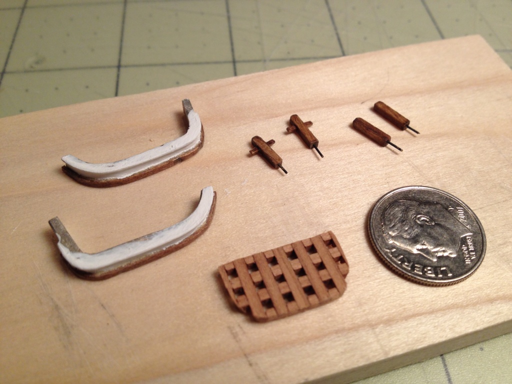
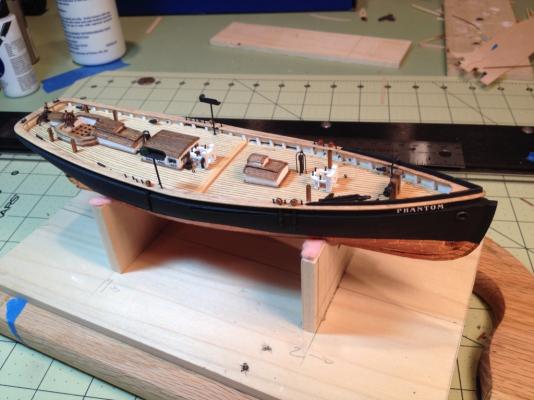
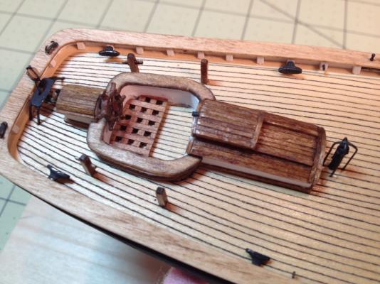
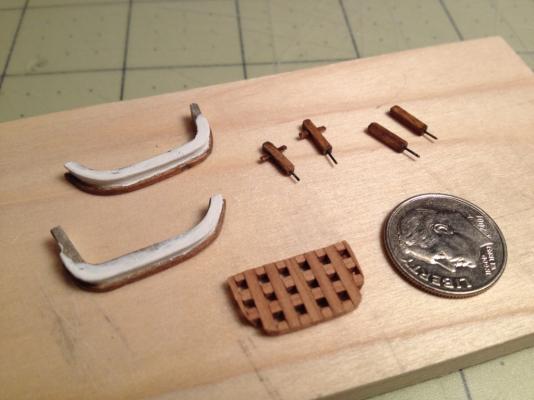
I've completed all the pieces and installed the wheel house, cockpit coaming, companionway and the stove pipe. The coaming pieces were a bit out of shape and needed to be bent to the shape shown on the plans. While doing the wheel house I noticed that the length of the shaft on the ship’s wheel was not very long and thought I might have a problem installing it over the coaming. To give the wheel more clearance I filed down the two coaming pieces to form a notch where the wheel house is located. I also decided to install a baseboard around the base of the coaming that matched the wheel house and companionway. Before installing the baseboard I filed down the metal rigid along the base of the coaming. I pre-bent and stained the wood strips before gluing them in place. I actually forgot the two bollards with the cleats were provided with the kit and didn’t remember until after I had started to make them (senior moment). I liked the the ones I started so I decided not to use the ones provided. I made them from the 1/16” square wood strip, cut to the length taken from the plans. For the cleats I notched the bollard and inserted a small piece of wood. I decided to use the grating that is provided although it’s rather large for this scale. The only modification I made was to sand it down so it wasn't so thick. I glued the pieces together prior to sanding it and then cut it to shape. The wooden seat on top of the coaming was made from a piece of the 1/32” thick wooden sheet. Before cutting the seat out I sanded the piece down to about 1/64” so the seat wouldn't be so thick. I also notched this piece at the wheel house to match the coaming. For the inside of the cockpit I used a piece of manila folder painted white. After all the pieces were made I finally got to put it all together. I had to keep telling myself to be patience and let everything dry before starting. Even so I think the ploy on the grating was still a little tacky when I glued it down. I'm glad I notched the coaming and seat because the wheel never would have fit if I didn't. The stove pipe was painted black and the guard was made out of the 28 gage black wire. Took the pipes location from the plans a drilled all the appropriate holes for it and the guard.

- 139 replies
-
- 4
-
-
- phantom
- model shipways
- (and 1 more)
-
Thanks Wayne. It’s amazing what one can do if you have the right frame of mind. I don’t think I would have had the patience to do this five or ten years ago. I would have either slapped it together in a few weeks or started it and never finished. I do look forward to working on it and try to imagine how the actual carpenters would have built it. It is tiny though, maybe the next one will be ½” scale so I can see it without using glasses AND a magnifying visor.
-
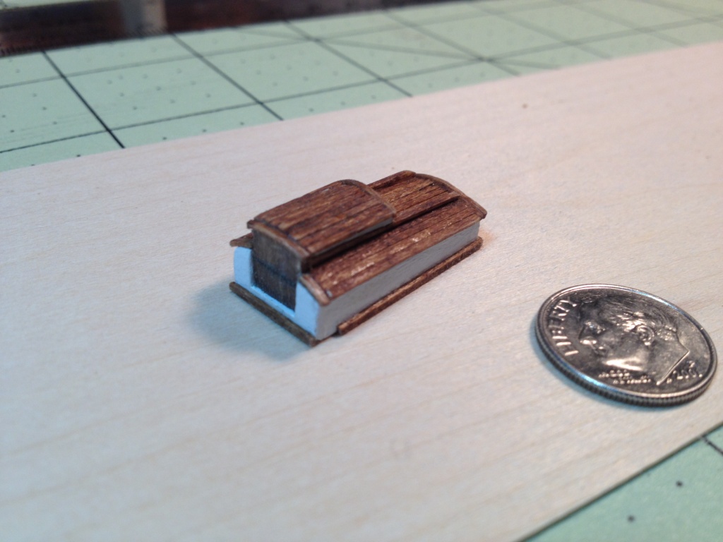
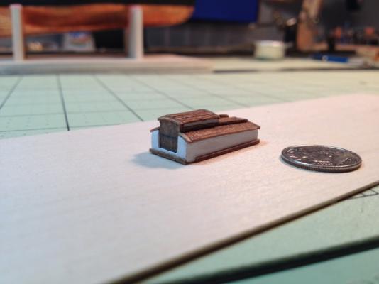
Here’s my interpretation of the cockpit companionway. I cut a 1” long piece of ¼” x ½” stock for the main body and sanded it down to the sloped shape. For the roof and sliding top I used more of the dimensional lumber. I installed the curved edge strips first and then placed the roof slats in between them. The rails for the sliding top were made from two pieces of lumber glued into an 'L' shape. I finished it off with the base board trim pieces. The only thing I need to add is the hasp lock.

- 139 replies
-
- 5
-
-
- phantom
- model shipways
- (and 1 more)
-
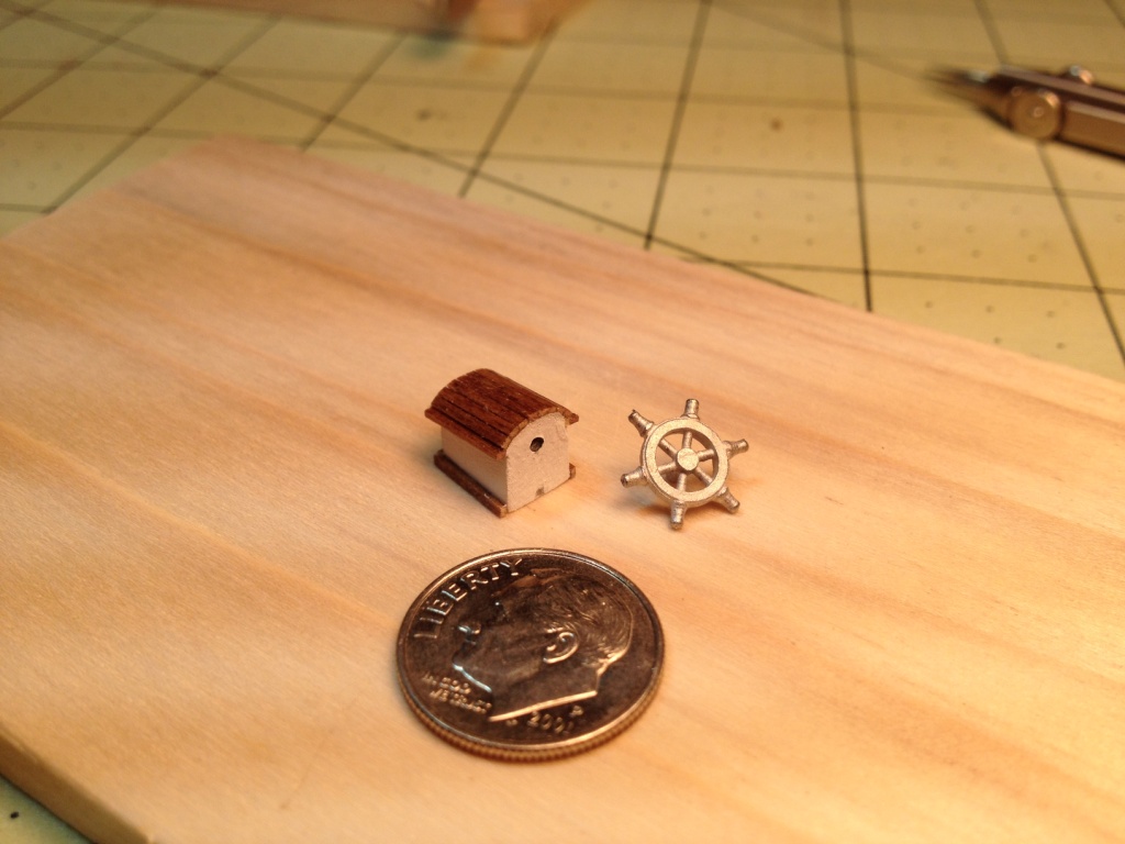
I reopened the shipyard this past weekend and started to work on the deck fixtures. Made the wheel house from the ¼”x ½” stock and cut it to dimensions taken from the plans. I then sanded the top to the appropriate slope and radius. After painting the piece white I used some of my scale lumber for the roof and baseboard trim. The lumber was stained prior to gluing it to the wheel house. Finally, I drilled the hole for the ship’s wheel that will be painted and installed later. The wheel house was only placed on the deck; I want to complete the cockpit coaming and companionway before gluing them all in place.


- 139 replies
-
- 2
-
-
- phantom
- model shipways
- (and 1 more)
-
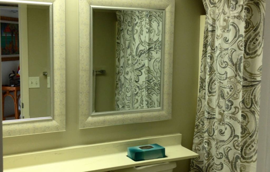
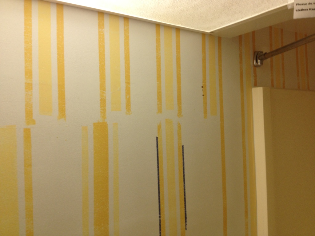
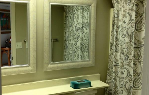
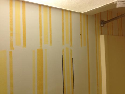
Hello all, nice to be back at home. Had a good time on vacation, didn't do too much just relaxed at the beach and pool. The admiral only had one project for me; repaint the bathroom. It’s a small room so it didn't take too long. The hardest part was sanding down the walls to remove all the ridges from the old painted striping. Hung new mirrors and installed new cabinet hardware. Before After I should be getting back to the ship in a few days, need to catch up on a few chores at home first; get the yard back in shape and weed the garden. I did indulge myself while on vacation. I visited my favorite hobby shop down there that I wish we had up here, and bought myself some dimensional lumber. Wahooooo!! Bought some HO scale 2x3 lumber (0.023”x 0.0345”) made by Northeastern Scale Lumber, that I thought I would use as trim on the deck fixtures.
-
Mayflower by SawdustDave - Finished
_SalD_ replied to SawdustDave's topic in - Build logs for subjects built 1751 - 1800
Dave, at least he went on the paper. Isn't that suppose to be good luck or something? -
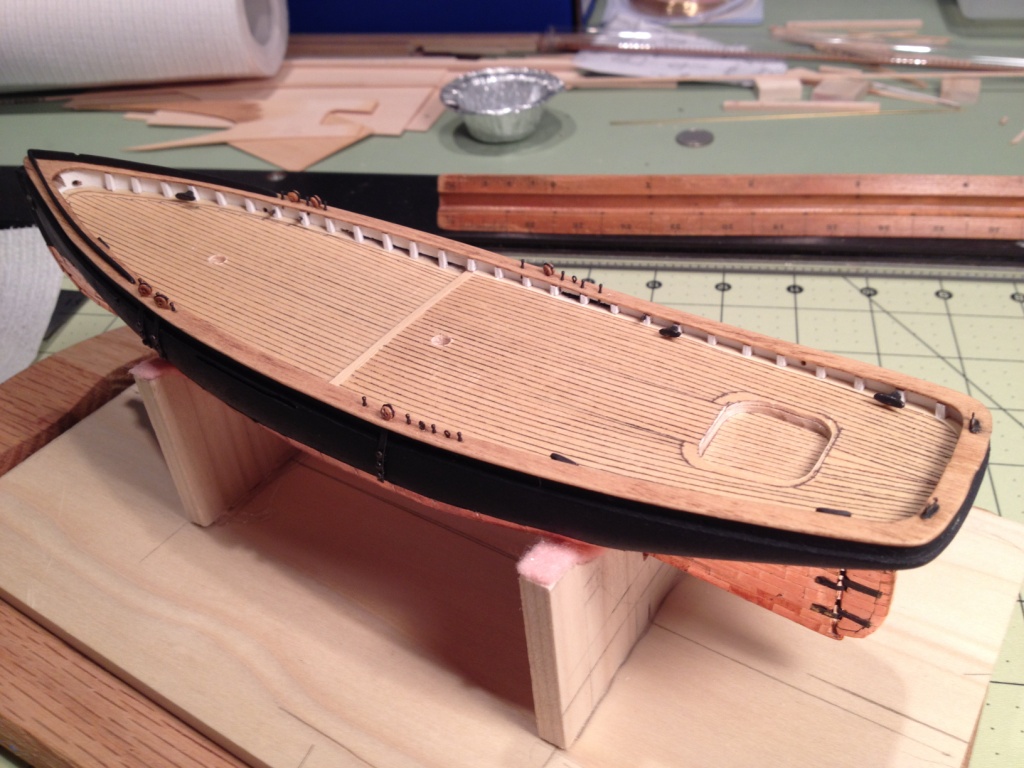
Chainplates were installed following Chuck's practicum. One thing I found easier to do was to pull the thread that is hooked onto the chainplate through the hole in the caprail from the top down and then hook on the chainplate and pull the thread and chainplate back up into the hole. I used a pin that I bent the tip on to push up through the hole in the caprail and then catch it on the tread to pull it down through the hole. I then drilled the holes in the hull for the nails to secure the chainplates. Tying the deadeyes to the chainplates was an experience. Next I located and drilled the holes in the caprail for the belaying pins and eye bolts and glued them in place. All the belaying pins, eye bolts and chainplates were blackened prior to installation. I decided to keep all the deadeyes and blocks their natural color. I also made an installed the traveler. I pretty much followed the practicum except that I soldered the legs to the top of the traveler. This will be my last post on my build for the next two weeks. The shipyard will be shutdown while the admiral and I go for a little R&R in the sunshine state.

- 139 replies
-
- 4
-
-
- phantom
- model shipways
- (and 1 more)
-
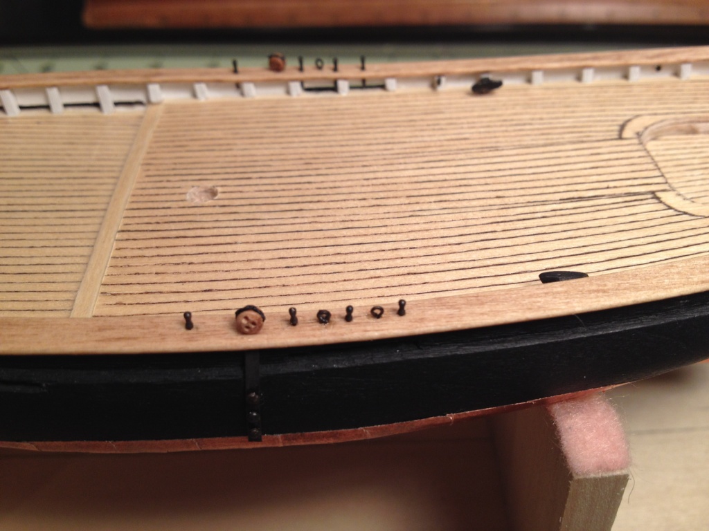
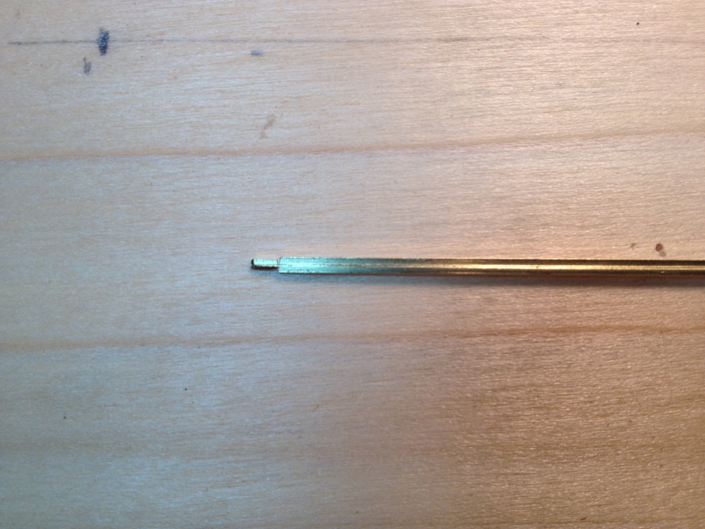
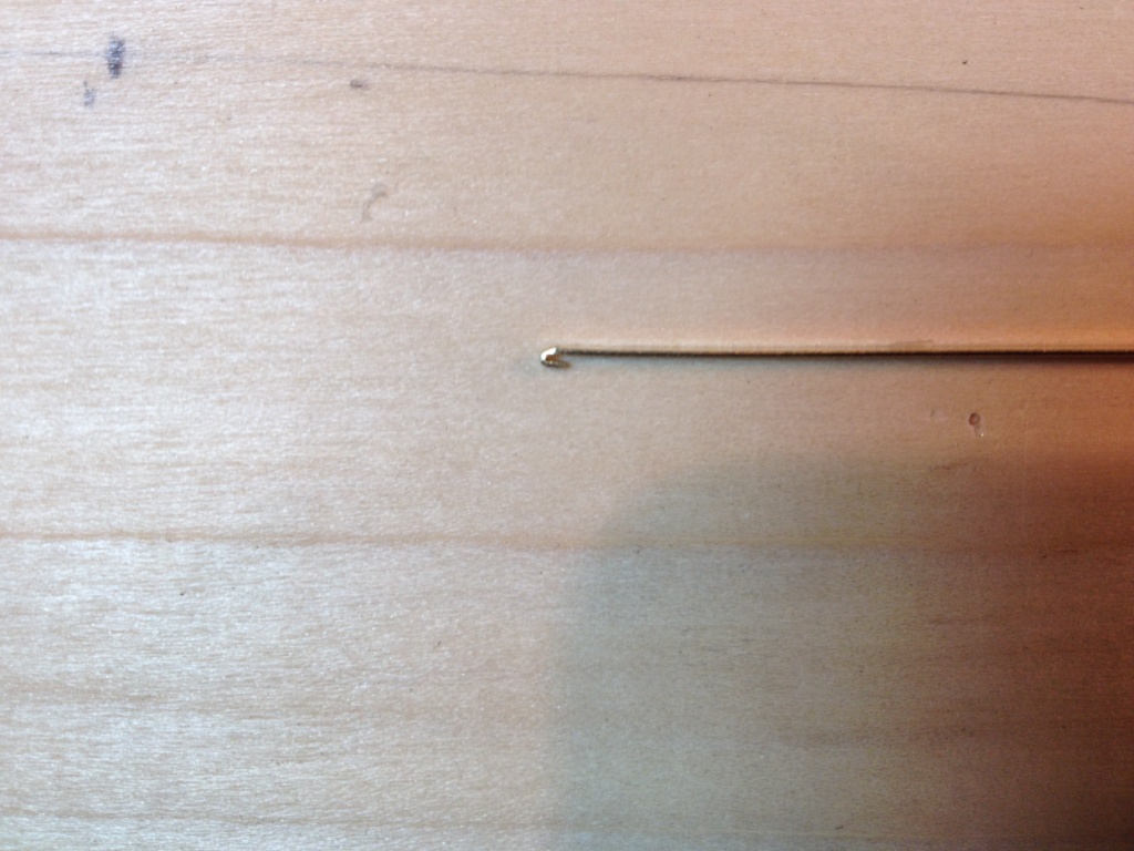
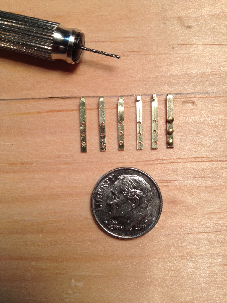
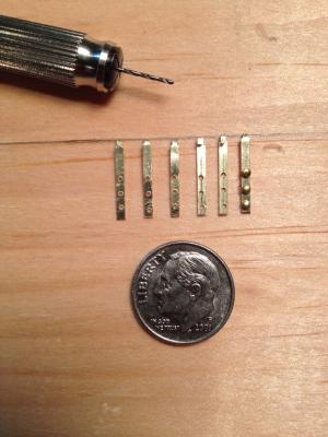
Chainplates done! My first thoughts when I read Chuck’s practicum on how to make these plates was ‘you've got to be kidding! ’ But taking some advice of one of my old professors, I had a good cry over how this is impossible and there’s no way I can do this and then got down to solving the problem. After two trial attempts on some scrap brass strips and three failed attempts at the real thing I finally came up with a method that worked fairly well for me. Some of the problems I had while working on the trial pieces was getting the drill bit to bite into the brass while at the same time trying to keep the holes in line and spaced properly. I tried using a punch (brad) but all that did was dent the strip and it was still hard to line up the punch marks. What I finally came up with to keep the holes in line was to scribe a line down the middle of the brass strip with a steel point. I discovered later while drilling the holes that this not only helped with keeping the holes in line but also made it easier for the drill to bite into the brass. To mark the location of each hole I made another scribe mark perpendicular to the center one. This in effect made a center mark for the drill bit. Once I made one plate that I was satisfied with I used it as a template for all the others. Below are some of the other steps I preformed while making the chainplates. 1. Filed down the top portion of the plate that will form the hook at the top. Found it easier to work with the entire brass strip and not cut it to size until I was finished with the piece. 2. Form the hook using a needle nose pliers and bent it around the tip of a pin. At this point I test fit the hook into the hole on the caprail and marked where the first bolt hole should be located. 3. Marked the bolt hole location, one at a time, and drilled the hole. Repeated for the other two holes. 4. Marked the end of the plate and sniped it off the strip. Note that all the scribe marks were done on the back of the plate. And sorry for rambling on so.
- 139 replies
-
- 3
-
-
- phantom
- model shipways
- (and 1 more)
-
Wayne, thanks for your continued support, and if you find a way to motivate your boys let me know so I can try it on my daughter. Patrick, welcome back; hope you’re more relaxed. Glad you like the deck and the rail.
- 139 replies
-
- 1
-
-
- phantom
- model shipways
- (and 1 more)
-
Mayflower by SawdustDave - Finished
_SalD_ replied to SawdustDave's topic in - Build logs for subjects built 1751 - 1800
Superb work Dave. I’ll be following to learn all I can.