


JSGerson
-
Posts
2,163 -
Joined
-
Last visited
Content Type
Profiles
Forums
Gallery
Events
Posts posted by JSGerson
-
-
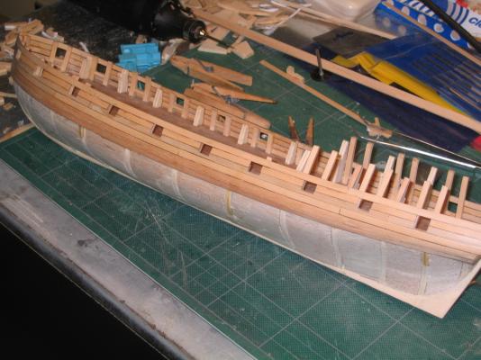
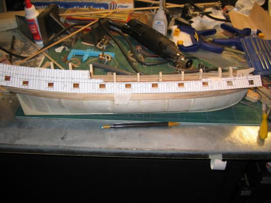
More pictures of the gunport planking

-
In constructing the gunports it was necessary to remove part of the kit bulkheads. Eventually all expose kit bulkheads would be removed. Although the practicum did not call for it at this point (it would a few steps later), the keel extension in the bow was removed and replaced with other pieces as instructed by the practicum.

-
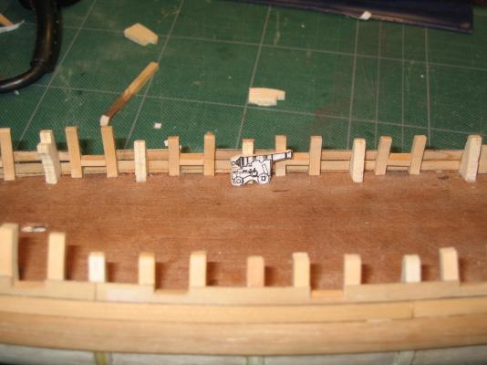
In ensure that the bottom of the gunport was at the proper height off the deck, I made a template of the cannon and used it to measure the top of the sill.

-
Because some of the gunports have lids and others don’t, a lip had to be constructed around the openings for those that did. Here is a picture from the practicum as I do not have a picture that depicts it.
- goatfarmer11, Torrens and coffeebeans
-
 3
3
-
In this instance the alignment used the kit bullheads. If they were off… ripples and ripple effect.

- goatfarmer11 and Torrens
-
2
-
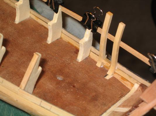
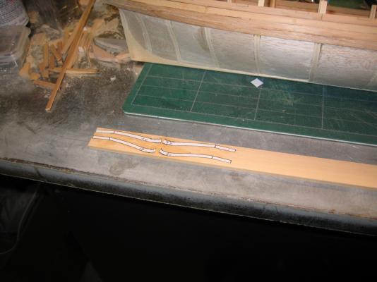
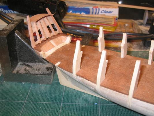
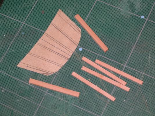
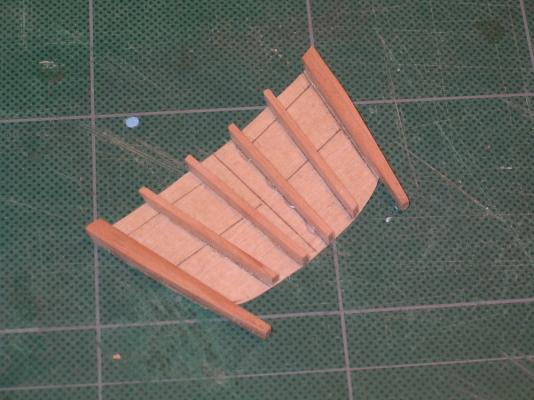
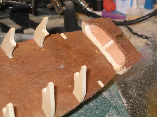
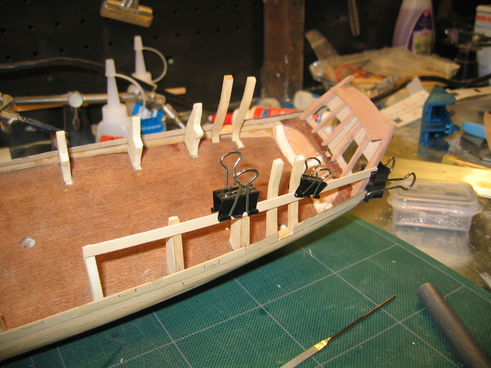
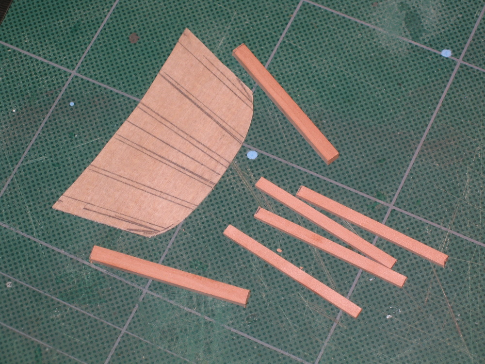
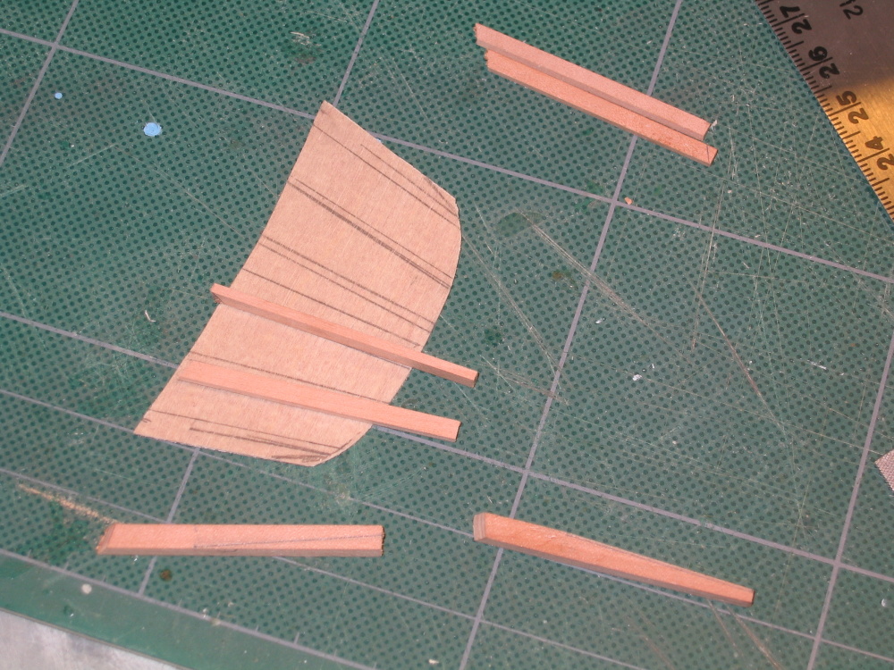
The practicum implies that all of the gunport openings be cut out at this point. Then a sill added to the interior base of each opening. And finally false ribs are added to each side of the gunport. Not trusting myself, I did it this way but one opening was completed at a time.
The false ribs templates are again created from the Hahn plans, but what I did not fully comprehend about the Hahn plans was that they were designed to used to build the model with the Mr. Hahn’s method of construction. Therefore the ribs shown in the plan have extension on them to fit onto a construction jig. Once removed from the jig, the frames are cut to size. The practicum instructs you to construct the false ribs by using portions of the full rib. If I were to do it over again, I would have left the extension on and used them for lining and adjusting of all the false ribs during installation. Then I would have cut them off.

-
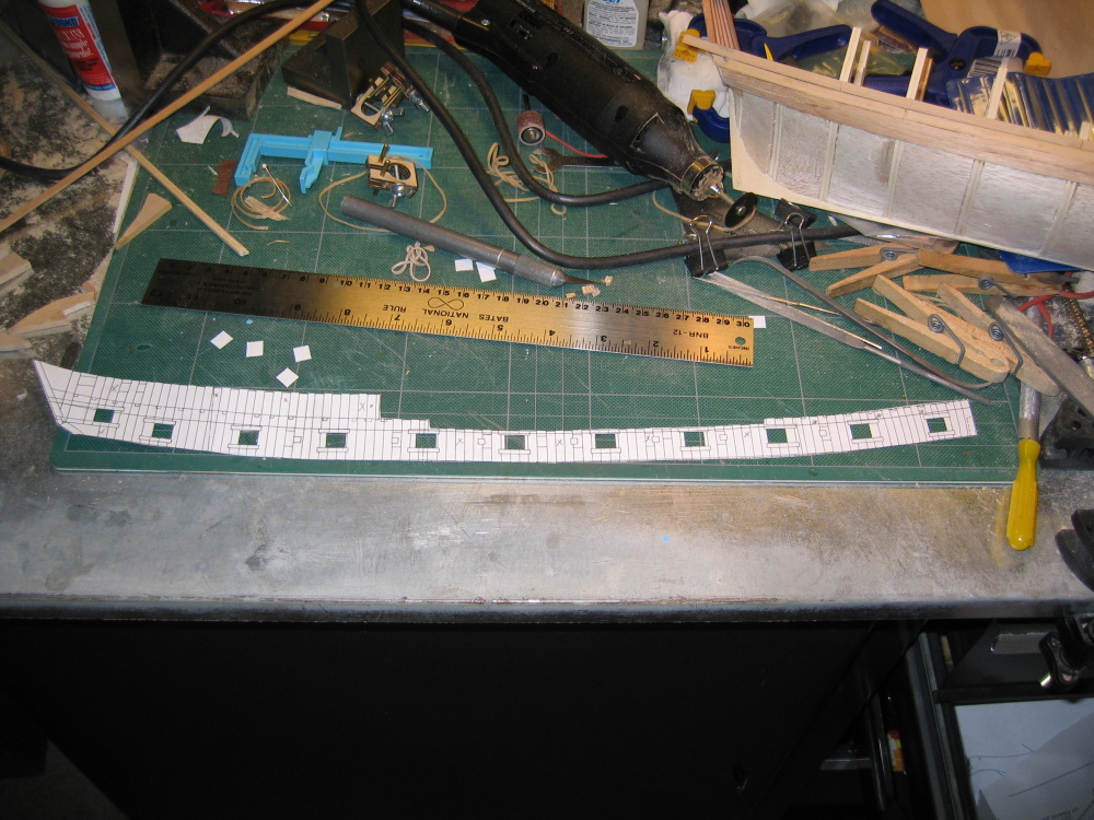
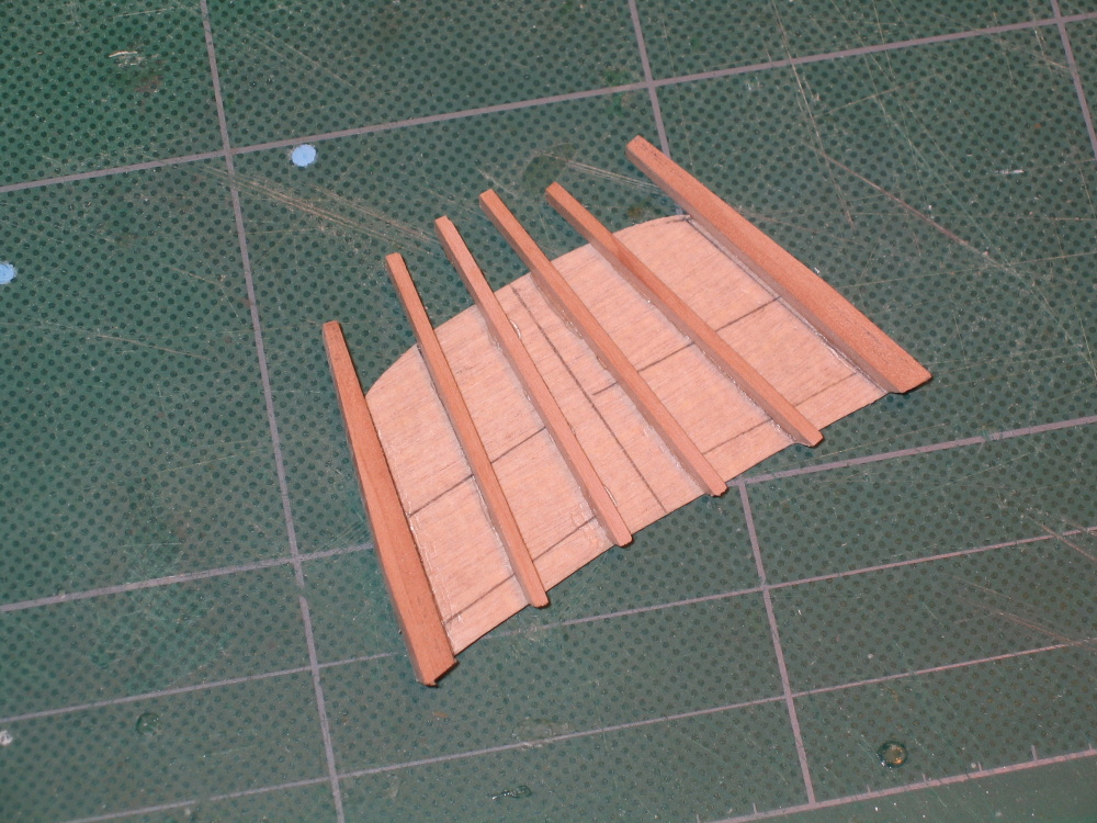
The template then was laid across the second row of planking above the wale to mark each gunport with pencil
-
Gunport Planking
The planking above and below the wale is single planking and therefore simulating actual planking. To do this the planks are cut to a scale for 24’ – 30’ lengths. The butts of adjacent rows are at least 5’ apart. Two rows above the wale are installed and sanded flush with the wale. Sorry, no photos at this stage.
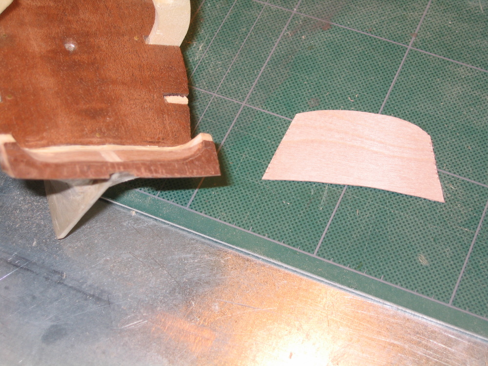
The template that was used to establish the wale line now has the gun port opening cut out

-
Counter Planking
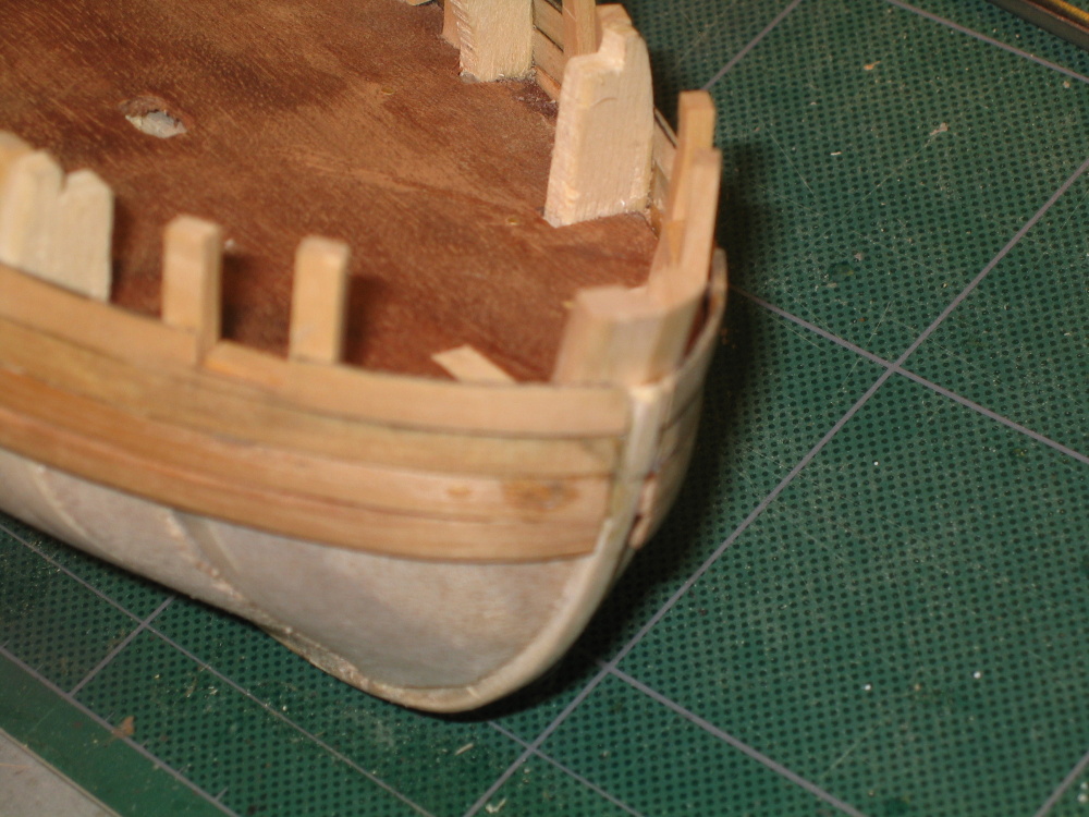
Using boxwood with the side blacked with artist chalk to simulate caulking, the first plank was laid at the bottom of the transom. The rest were installed to the bottom of the wale.
This was my first inkling that something was amiss. In the practicum it took 5 planks to accomplish to this task. My model only needed 4 planks. It was too late now, so I pushed on knowing trouble was coming (the ripple effect).

-
This repeated again for a second strip below the first. Here you will notice my lack of experience in preparing the stern for the planking. There is a gap near the stern between the hull surface and the planking. As far as I know it didn’t affect the model.
-
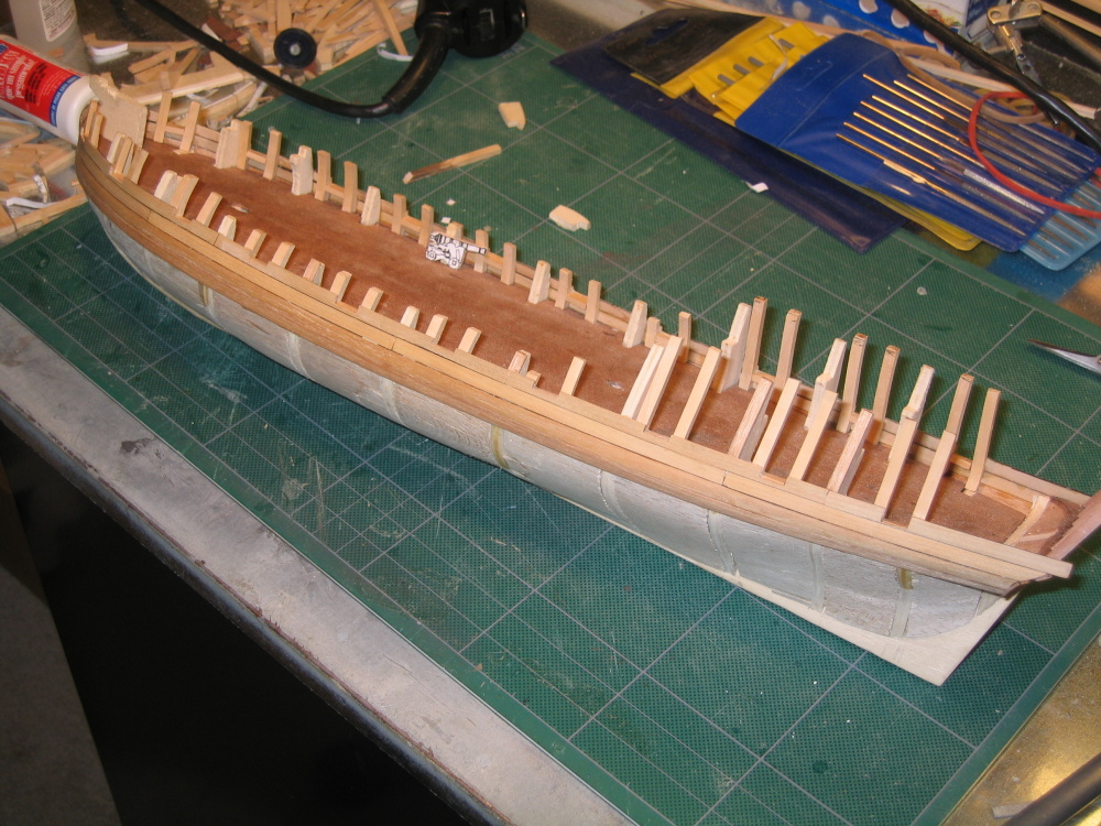
Because the wale is thicker than the rest of the planking, the wale is double planked. The first layer is basswood and the second ebony. My wood package did not come with ebony, but walnut which I had to paint black. This first planking will obviously not be seen so the practicum has it applied as one piece. After it was fitted and beveled to fit in the bow rabbet joint, it was glued down working my way back to the stern.

- goatfarmer11, u21rw87 and maddog33
-
3
-
CHAPTER 2 – The Upper Hull, Scratchbuilt
Upper Planking
The wales
Mr. Hunt addresses and emphasizes the key in model ship construction is that everything is dependent and related to each other. It’s the ripple effect. You do things right, and things go easier; you do them poorly, not so well. I did not realize at the time, how I would learn the truth of that. With that said, I started my first real planking process.
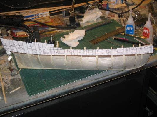
The practicum starts at the wales. Using the Hahn profile drawing, I cut out drawing and pasted it to card stock – office file folder. Following the instructions of the practicum, the template was located and placed on the model careful to keep it flat. That meant to NOT wrap it around the hull. The 2D image on the template was what one would see looking from the side, not the actual 3D shape. I had this problem earlier with the transom window openings. The wale line was then marked in pencil on the hull. This was repeated on the port side with the template reversed.
- maddog33, Torrens, goatfarmer11 and 1 other
-
4
-
This concludes Chapter 1 of the practicum. I am presently working my way through Chapter 8 of 9 with an additional couple of chapters for the rigging. As soon as I write up Chapter 2, I will post it
-
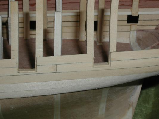
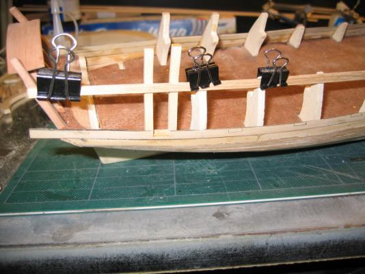
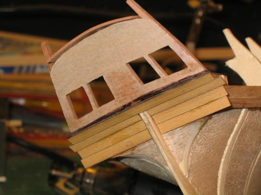
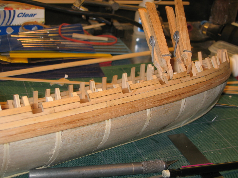
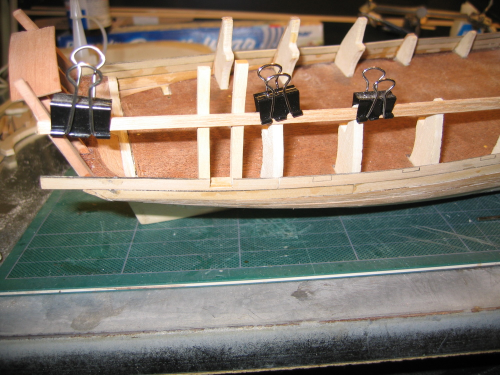
Using a piece of 7/16” x 1/32” swiss pear you are instructed to create a cap that goes across the top of the interior timbers which I did.
It was to be trimmed at a later time. I was never really content with this but kept it on until it was inadvertently knocked off. I didn’t bother to put it on again till I felt I needed it.
-
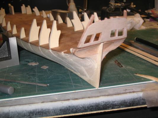
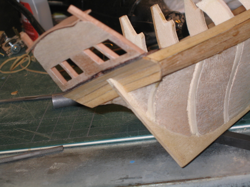
Now I glued the transom to the stern. As I mentioned earlier I ran into a problem later on when I was determining where the rudder stem came through the decks. I’m not sure, but this is where I may have made my mistake and given the transom an improper angle thus shortening the deck. By the time I realized it, I had to make some compromises which I will discuss then.
-
The transom timbers became part of the frame for the window openings. Again, the location of the transom windows is based on the Hahn plans. The practicum then instructs you install the transom to the stern before the start of the window construction. Contrary to this, I created window openings while the transom was off the model. I felt I could make cleaner cuts and manipulate the transom easier. In most models of the Rattlesnake there are four windows and a center panel. Mr. Hunt elected not to create the center panel for this model.
- Don, maddog33 and goatfarmer11
-
3
-
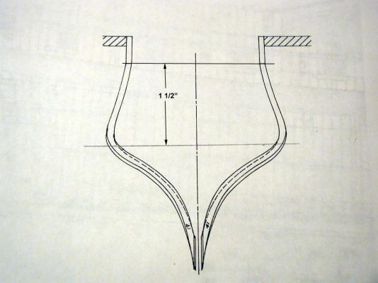
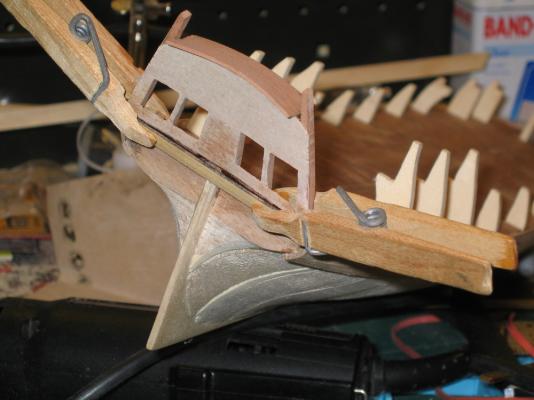
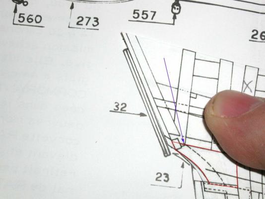
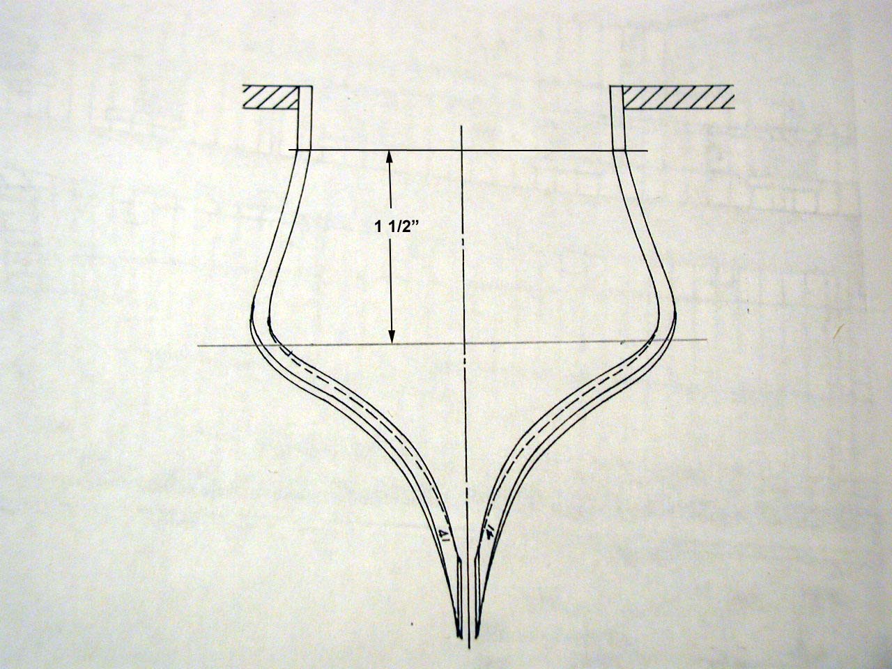
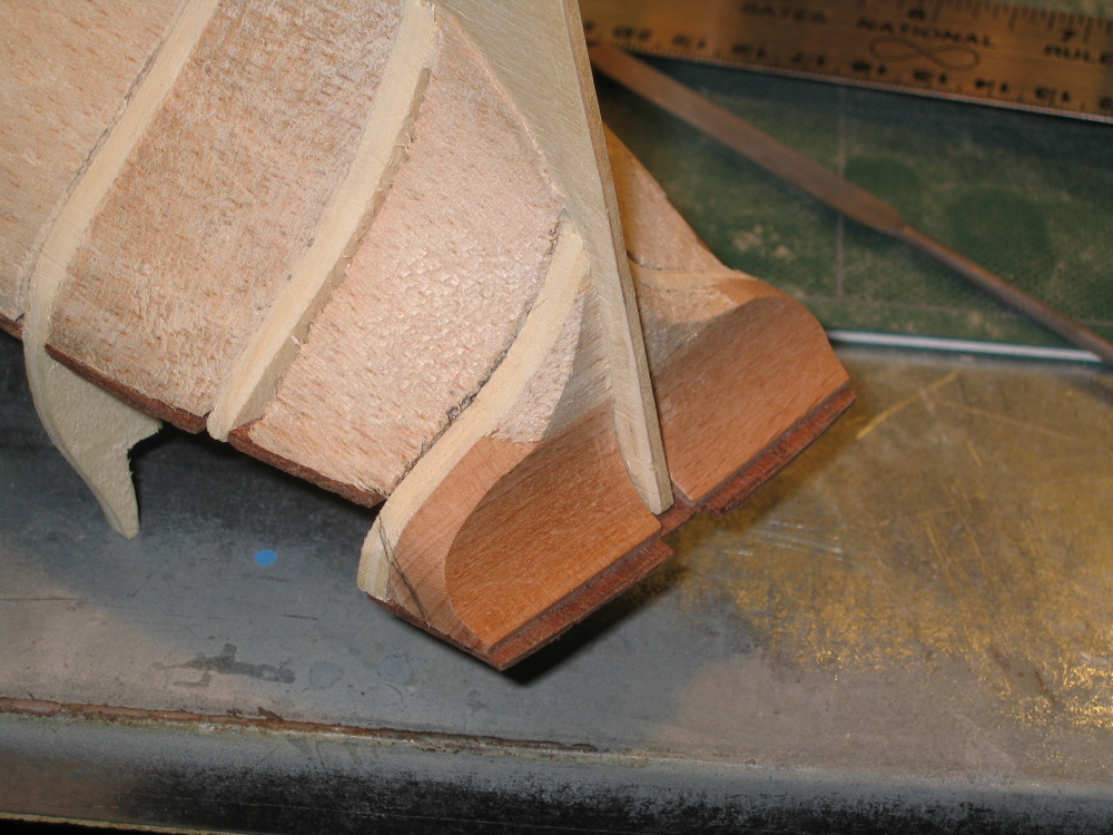
Next came the transom timbers which were cut to size. You will notice that the outer timbers are not uniform in width, but taper starting about ½” from the bottom.


-
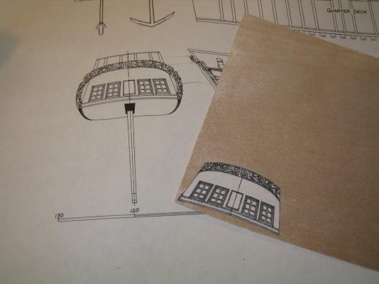
The head on image of the transom is not what a draftsman would call a “true view.” The top the transom is angle forward to the viewer and therefore the image is foreshortened. If I were to just cut the image out and paste it on the plywood it wouldn’t be wide enough. So I scanned the image and based on the true width from the side view which looks at the transom on edge, I stretched the full view so that the height had the same dimension as the side view and then printed it. My high school mechanical drawing classes finally came in handy. It doesn’t hurt to have a degree in Civil Engineering either.

-
Then the hard blocks in the counter had to be slightly modified to conform to the Hahn plans. This got a little confusing and I must have done something wrong somewhere in all this but did not know it at the time. I only realized that things were a bit off when I went to figure where the rudder post came through the deck. I talk about that later. Anyway, at this time I thought everything was hunky-dory and was ready to take on the transom. The practicum requires that I purchase some 1/64” plywood. I didn’t even know they could make plywood that thin and its 3-ply!
The practicum has you use the Hahn plan’s image of the transom as a template to cut out the overall shape of the transom from the plywood. It would seem to be a straight forward operation.
-
-
The kitbash calls for making the deck below the stern quarter deck (nautical term?) visible in contrast to the original kit. After transferring lines from the Hahn’s plan as described in detail in the practicum, I carved out a cavity in the stern using a sanding drum on a Dremel rotary tool.
-
The Stern Transom
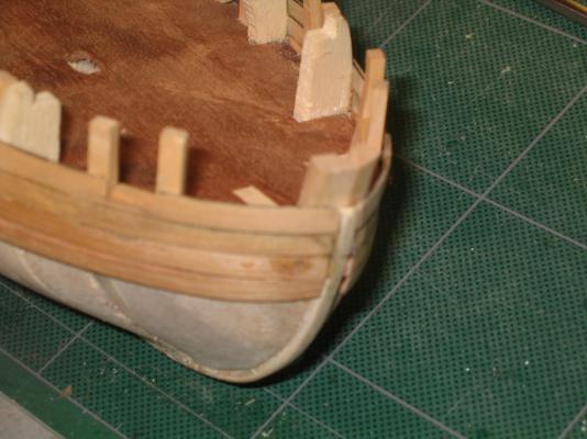
Now it starts to get interesting. The practicum allows you to follow the original kit plan or jump off the deep end and start to perform major surgery from which there is no return and you are duly warned. So I took a deep breath and took the plunge.
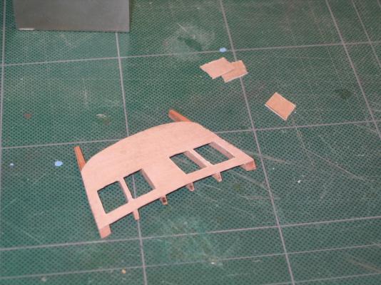
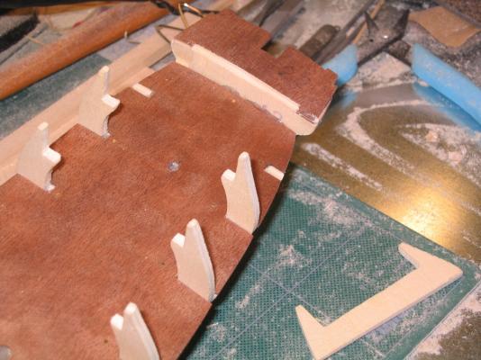
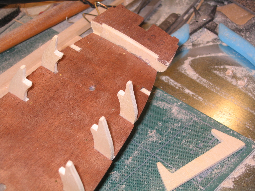
The first thing I had to do was remove the stern bulkhead #12
You can see the squarish U-shape part I cut off to the right
-
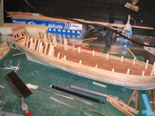
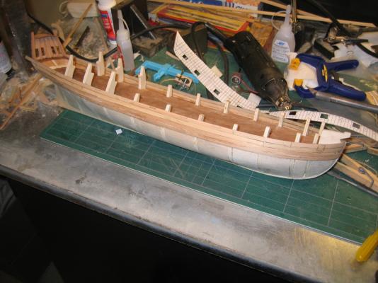
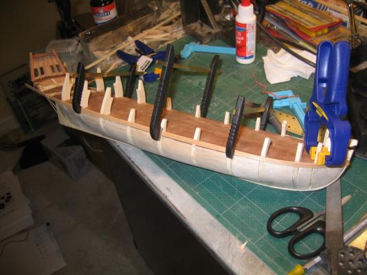
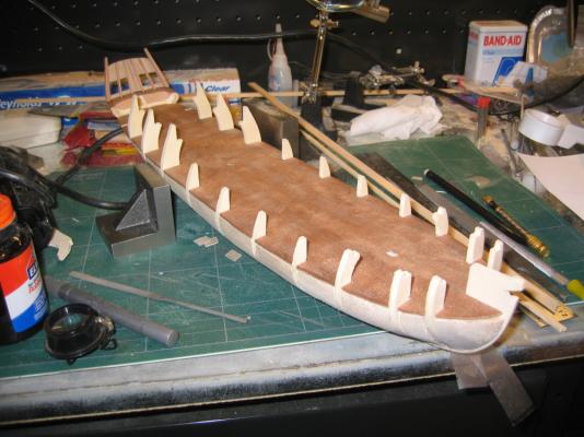
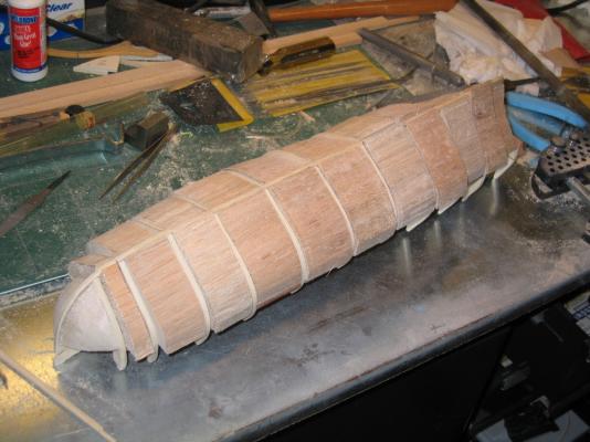
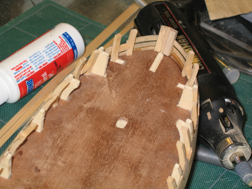
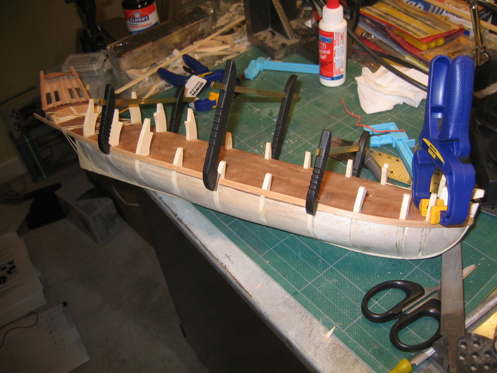
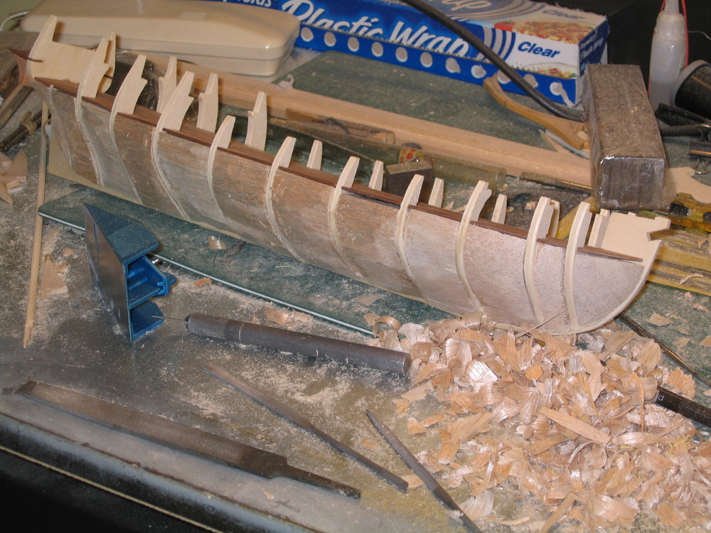
Balsa Filler Blocks
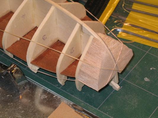
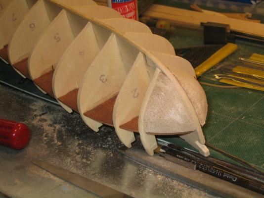
In order to facilitate the planking operation Mr. Hunt suggested using balsa wood filler blocks between the bulkheads. This effectively turns the bulkhead frame into a solid hull which eases planking and strengthens the model walls. You will notice there are small gaps between some of the bulkheads and the balsa. I felt tight fit of the balsa to the bulkheads either through custom fitting or wood filler wasn’t really necessary because first, the use of the balsa was optional to begin with, second they are just an aid for shaping the hull, and lastly all open spaces were going to covered by planking. But, based on my vast knowledge of ship building (Ha!), I could be wrong.

-
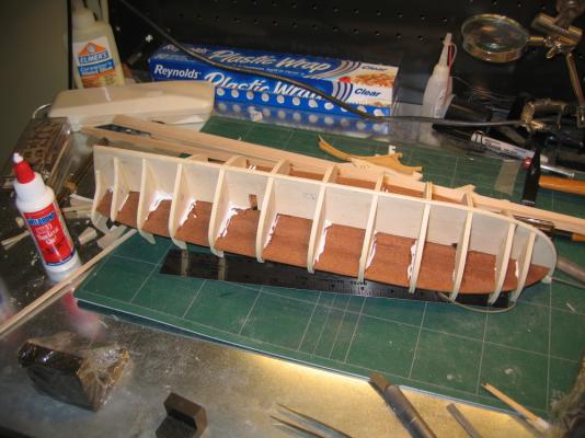
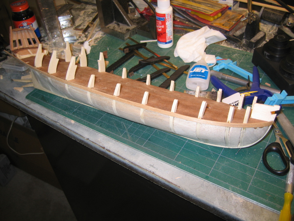
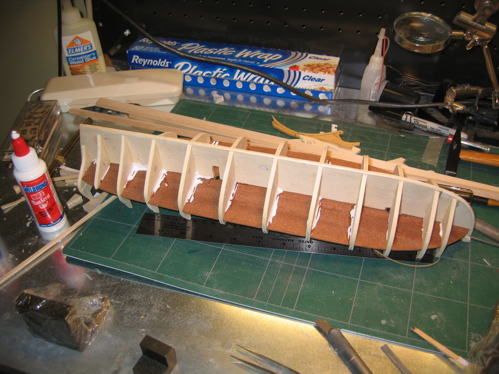
False Deck
Once more Mr. Hunt cautions the builder to make sure that the bulkheads don’t have any high or low spots where the false deck is to be installed. Again I tried to keep this in mind, but may not have been as successful as I thought as I did have some problems in this area as well later on.
The false deck is a bugger to put on due to the curvature of the deck structure and false ribs. It just doesn’t drop on the bulkheads. You have push, twist, bend, and pray it doesn’t snap. If it doesn’t feel right taking it off is as much a pain as it was putting it on. But once on, I glued it tight and didn’t spare the glue. Any excess would only show under the deck where it wouldn’t be seen.


Rattlesnake by JSGerson - FINISHED - Mamoli - 1:64 - Using Robert Hunt’s practicum
in - Kit build logs for subjects built from 1751 - 1800
Posted
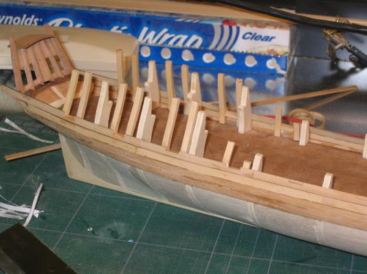
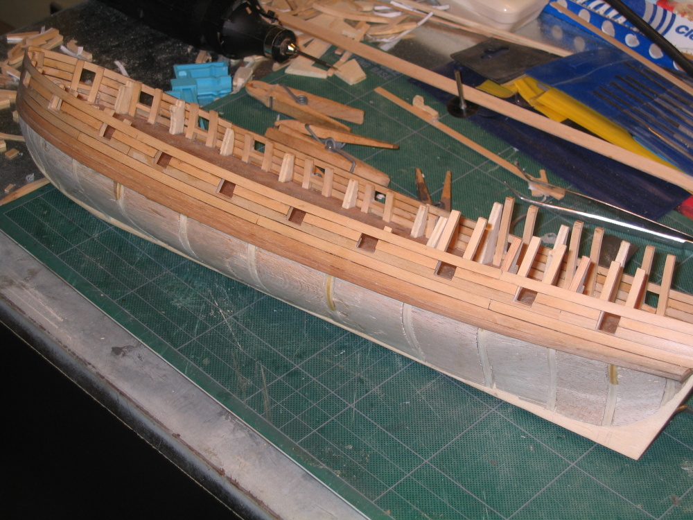
Oar Sweeps
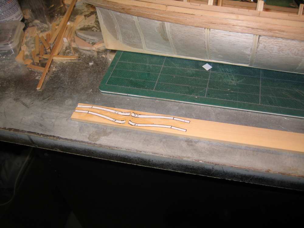
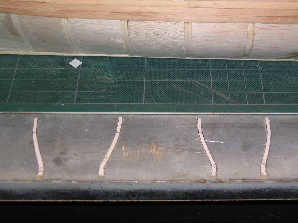
Once more the side view template comes into use to transfer the oar sweeps with pencil. Small holes were drilled, expanded, and filed to size. The oar sweep frame was then constructed off the model and installed
The top sills of the gunports were installed next