


JSGerson
-
Posts
2,646 -
Joined
-
Last visited
Content Type
Profiles
Forums
Gallery
Events
Posts posted by JSGerson
-
-
Sorry, no brass cleats as far as I know. You could just paint these steel cleats with brass paint and because of their size, no one would know the difference.
Jon
-
Quote
When I had the full-size scale copy of the USN plan’s gundeck details printed and laid down on top of the false gun deck
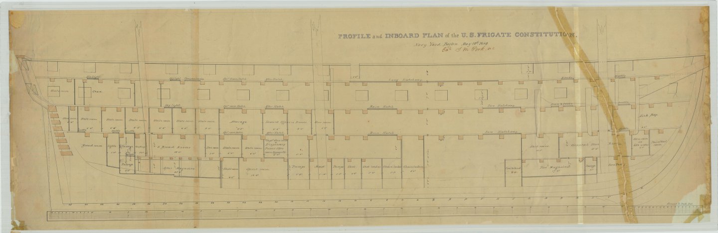
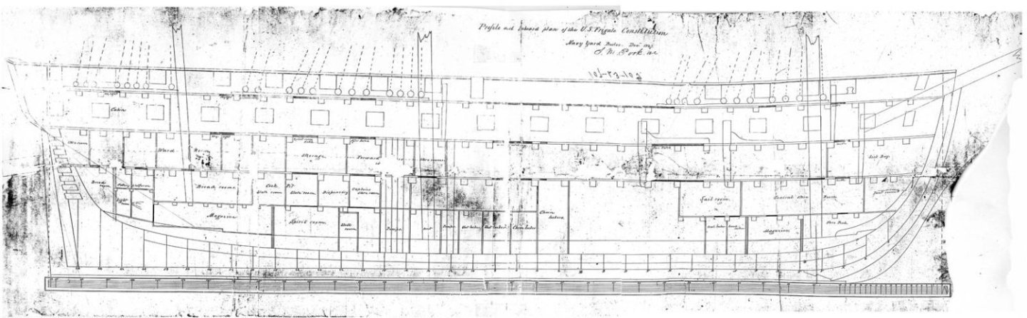
Just be aware of which era USN plans you are using. If I remember correctly, you are planning an 1812 version model and the present version of the ship has changed over the years. I have not checked, but the gun port opening positions may have moved around a bit since 1812. Just to be sure, here are two USN hull plans from 1849 (sepia color) and 1847 (B&W) that you may want to verify your port positions.
Jon
-
I don't know where you got that picture of the guard rail ether, so I added it to my collection. It doesn't look so much as a restoration, but more of a museum display. I did find a pre-restoration image of the guard rail which I believe does somewhat confirm the gaps between the guard rail and the fighting top.
As for the cleats, you may remember I had a method of making very small metal cleats which I documented (post #720) in my log back in June 2023 when I added cleats to the bow bulwarks next to the seats of ease. All I needed were some flat head nails, a Dremel rotary tool, hand files, and a disc sander. The resulting cleats were strong and embedded into the wood for easy gluing. You might want to consider this method at some point.
Jon

- mtbediz, Stevenleehills, Geoff Matson and 3 others
-
 5
5
-
 1
1
-
Based on all of your research and time you spent figuring all this out😵💫, I will accept you as my guiding authority and most likely will fabricate my fighting tops to look like yours. Well done!!!
Jon
- mtbediz, GGibson and Der Alte Rentner
-
2
-
1
-
Nice photos capturing all the detail on the bobstay collars. Oh yes, the bobstay collars look great too.🙂
Jon
- mtbediz and Der Alte Rentner
-
1
-
1
-
I don't know if this helps, but I checked one of my nautical dictionaries and the term "deal" means:
Fir wood, of similar thickness to plank.
So, I assume that "item 30 - "deals overlap," means where the 90 degrees planks overlap to each other.
Jon
-
-
Welcome aboard!
QuoteKeel
The first few words on page 1 of the instructions say:
"Pin clown on a flat wooden board ..."
I looked unsuccessfully through all the parts for the clown, but finally realized that the instructions have some errors in translation.
Although I'm constructing the MS model (with some kit bashing) I do have the pre-fire Mamoli plans & instructions and looked up the "clown" reference on my plans. It was not an error in translation, but poor printing. The correct word is "down" -> "Pin down on a flat wooden board ..."
I don't know if you have researched any of the recent and past Mamoli builders of the Conny, but you might want to check BruceWayne426 in progress build and Bill Edgin's (Robnbill) completed build. It looks like you are off to a good start.
I look forward to your future posts.
Jon
-
-
I don't know if it's the camera angle or what, but the gun barrel appeals to me to be low and not centered vertically between the lower framing and the top framing. The gun barrel must dead centered in the gun port. I had this same problem. I thought I had compensated for the gun deck with planking, but my guns sat too low. I never figured out where I screwed up. When it came time to actually install the guns, I found that the laser cut gun carriages that came with the kit did not match the US Navy drawings. They were shorter in height than the US Navy's. That is the reason I scratch built the gun deck gun carriages. Once fabricated, the new US Navy based carriages raised the cannon barrels enough to be at the proper height.
Double check your measurements. Place a copy of the hull plans directly on your model to see if the gun ports line up. Maybe the gun deck planking will correct my perceived concern. Better safe than sorry.
Jon
- Der Alte Rentner and mtbediz
-
2
-
-
That is a great solution, I'll steal your idea and do the same thing when I get to that stage.
Out of curiosity, the images of the of the bobstays on the actual ship appear to be photos made of images on a computer screen. Why didn't you use the original jpg file? If you don't have them, I do (of course I do 😁) if you want them. I can also provide the link to the source material they came from.
Jon
- mtbediz and woodartist
-
1
-
1
-
These are questions that the USS Constitution Museum might be able to help you with.
Jon
-
Another job well done. The wood contrasts add a nice touch.
Jon
- Der Alte Rentner and mtbediz
-
1
-
1
-
-
Very nice!
Yes, I know that "two steps forward, one step back" dance too, even more so with a couple of side steps and a twirl or two!😁
Jon
- Der Alte Rentner, mtbediz and GGibson
-
 3
3
-
Neat jig!
Jon
- woodartist and mtbediz
-
2
-
I would love to have that milling machine, but at this late stage of the build and my age ( I just turned 79 in November), I don't think I'll be building anything (if at all) nearly as challenging as this model that would require that tool, once my Conny is done.
I do have an idea as to how to fabricate the stairs that would not require a milling tool as be as precise as yours ... I think. We'll see when I get there. In the meantime, I'm still plugging away at rigging the spar deck guns. Things should pick up pace once they are done.
Jon
-
Nicely done! But I have questions; don’t I always.
- When cutting the steps, I assume you “dialed in" the horizontal distance with the X-Y table to be precise and consistent. How did you measure the vertical distance? I don’t have a real drill press, just a Dremel drill press stand which does not have any controls for precise measured movement vertically. Are there any controls on your dedicated drill press or did you just use a ruler or micrometer?
- How did/will you mate the stairs to the bowsprit? Did cut a bevel on the underside of the stairs, or flatten the top surface of the bowsprit? If you beveled the stairs, how? Did you use a scraper or something else?
Oh yes, don’t forget to provide a clearance notch under the stairs for the gammoning to pass through.
Jon
-
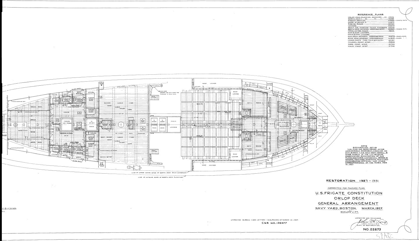
Heavy anchor chains were stored in the chain locker, located beneath the orlop deck (the lowest deck) and forward of the mainmast, in the bow section where the anchor chains would run down and coil when brought aboard. The rope cable or chains length varied but were about several hundred feet long. See attached plan.
On my model, I have both a cable and a chain traveling from the hawsers along the gun deck and down into pipes leading down into the chain locker.
Jon
- Stevenleehills, mtbediz, tmj and 1 other
-
4
-
-
They look beautiful! You didn't perhaps take pictures showing the sequence of steps you took to get the Bentinck shrouds into the state shown? Are the short shrouds sections coming off the the futtock stave, looping in the big ring or are they individually tied off at the ring? I understand your choice to omit some fine details due to scale; at full scale, there is an awful lot stuff crammed in there. But whatever you did, it look great.
Jon
-
I checked a number of books I have, and this one had an explanation and diagram of what may have been going on in the two photos I previously sent you. This may relieve your headache or regrettable make it worse. I hope for the former.
Jon
- GGibson, Stevenleehills and mtbediz
-
3
-
USS Constitution by rvchima - Mamoli - 1:93
in - Kit build logs for subjects built from 1901 - Present Day
Posted
May I suggest that you add filler blocks between the bulkheads especially in the bow and stern where there are tight curves and carve them so they conform to the curves of the hull. They will give you more gluing surfaces for the planks as well as help guiding the bending of those planks. You might want to sand the planks thinner at the curves so they bend easier too. This is a good place to practice your planking techniques so when you apply the second layer, you will have a nice surface to work with.
Jon