


JSGerson
-
Posts
2,156 -
Joined
-
Last visited
Content Type
Profiles
Forums
Gallery
Events
Posts posted by JSGerson
-
-
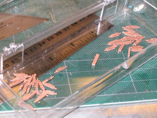
The axles
The axles took a bit more delicate touch. Once again from two 24” sticks of 1/16” x 3/32” swiss pear, 40 ½” pieces were cut. Where before the carriage sides were milled on two sides, the axles were milled on all four sides with the front and rear axles having different patterns. That’s a lot of milling! The result leaves you with square axles which then have to be filled into a cylinder shape 1/32” in diameter.
-
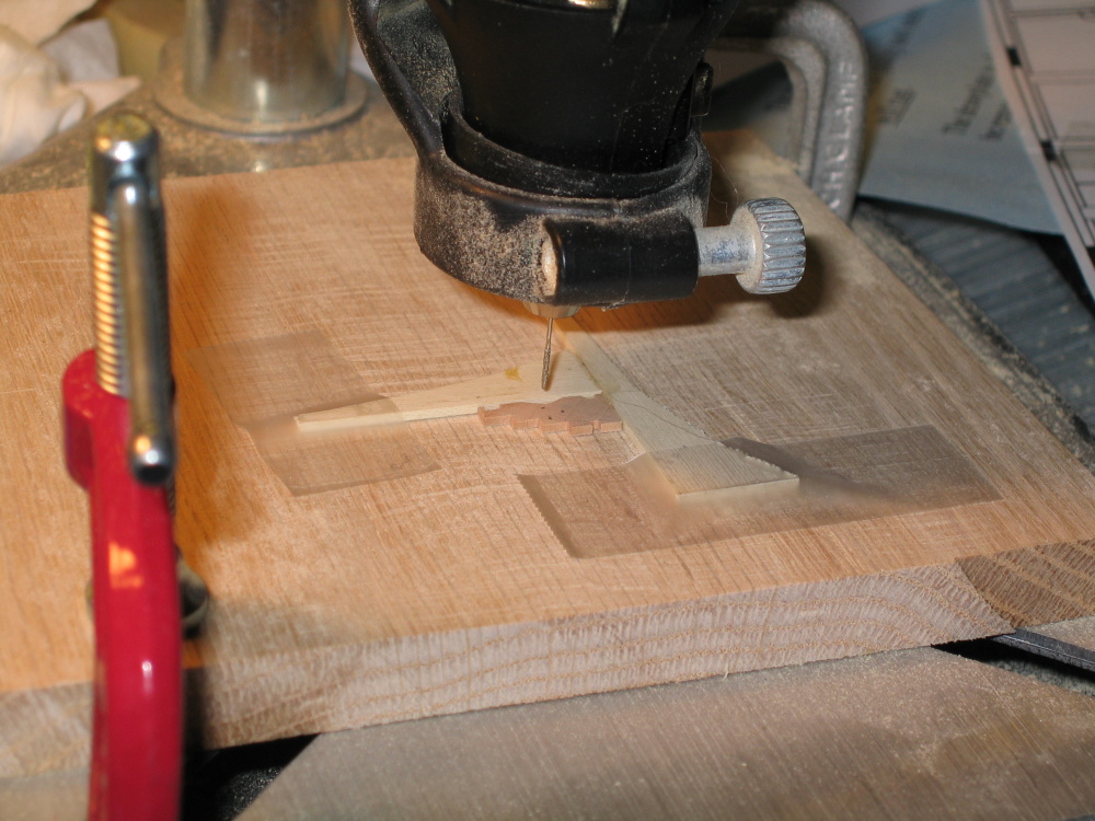
The side holes
I finally got a use for my Dremel drill press accessory I bought so many years ago. Setting up a jig as shown in the Practicum, the first of three holes was drilled in all 40 sides. Then the set up was adjusted and the second and finally the third hole was drilled. The first two were made with a #71 drill while the last was made with a #71 drill…or not!
CAUTION: Before drilling the holes make sure the eyebolts and wire that will eventually be inserted in them fit properly. In my case, I realized that the holes I made could have been made smaller.

-
Then like cutting a loaf of bread, 40 3/64” slices are made.
-
CHAPTER 7
Cannons and Carriages
When I started this little cannon project, I did not fully appreciate the amount of work and detail involved. Would I do it again?…yes.
The Cannon Carriages
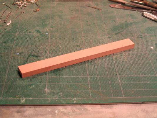
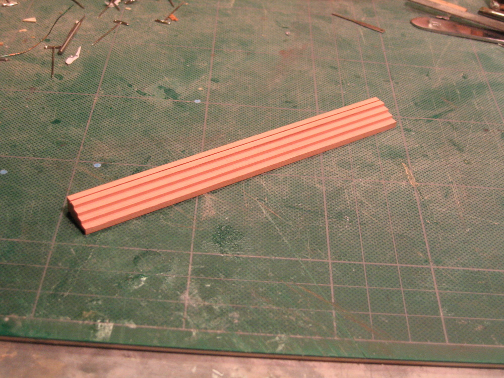
The sides
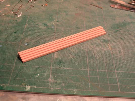
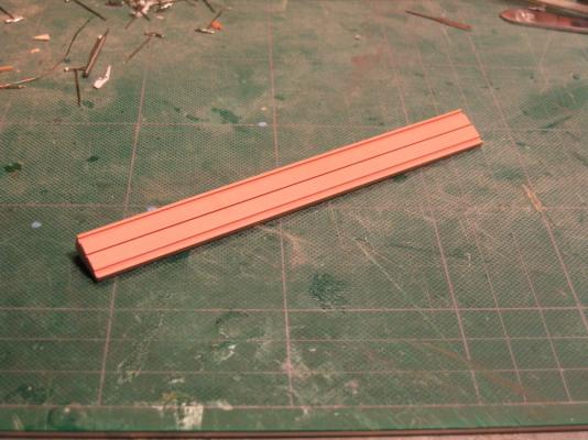
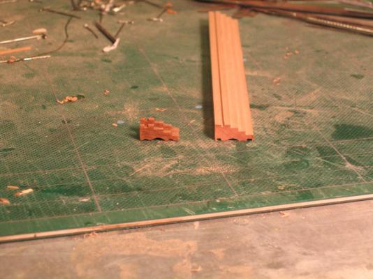
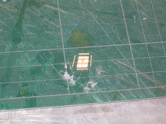
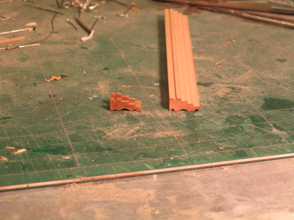
The carriages start out as a 6” stick of 5/8” x 9/32” swiss pear which then was milled using the Byrnes tablesaw. Groves of various widths and depths were cut along the length as directed by the Practicum on both sides of the stock wood. On the bottom side the Practicum directs the builder to widen and shape center grove is widened using a D8/7 gouge to a rounded trough. Not having a gouge, I used needle files to get the same result. As a comparison, the picture below shows the milled wood stock and the premade carriage from the kit.
-
All the carvings got a coat of Poly-wipe. The figurehead and the stem carvings are to be installed at a later time.
End Chapter 6
-
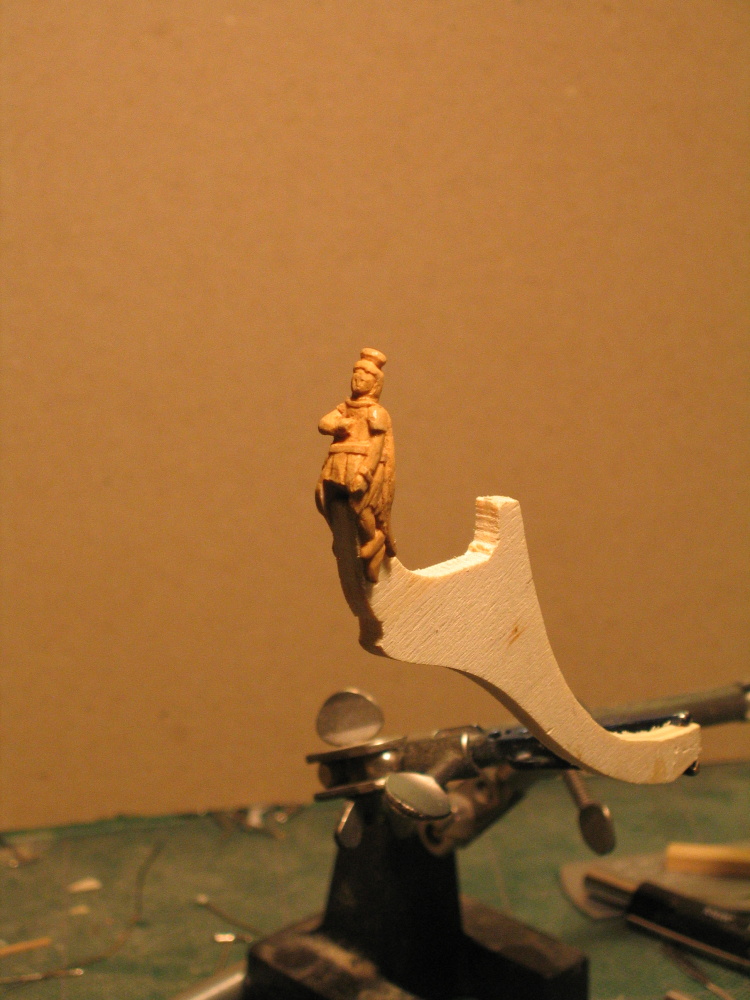
The last touch was to add the sceptre which nothing more than a pin with the point and head cut off. A hole was drilled into hand and the scepter was inserted. It was snug enough that no glue was necessary.
-
This took a while as I went slowly, refining the cuts over and over.

- Duanelaker and janos
-
 2
2
-
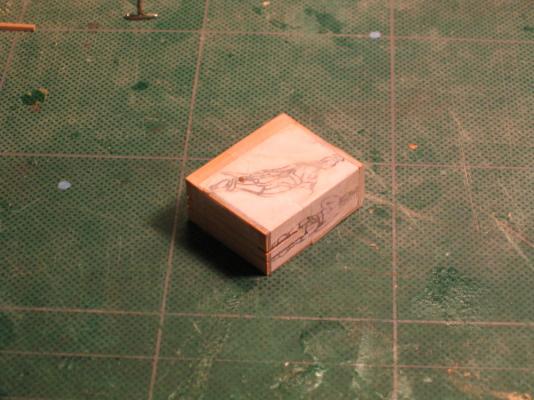
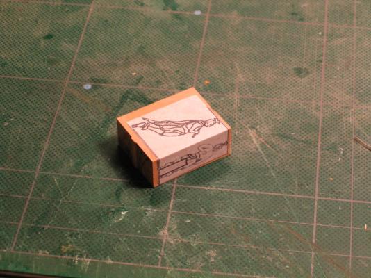
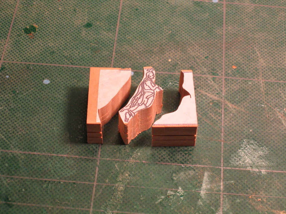
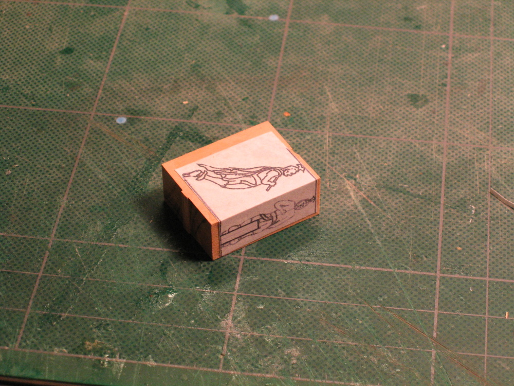
As an aid in my carving, I pasted another template on the block carving.

-
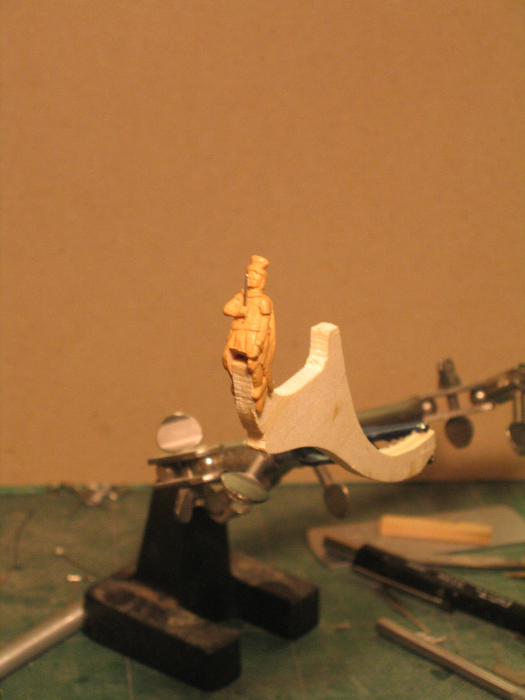
The first thing that had to be done was add the notch where it will attach to the stem as well as my temporary holder.

-
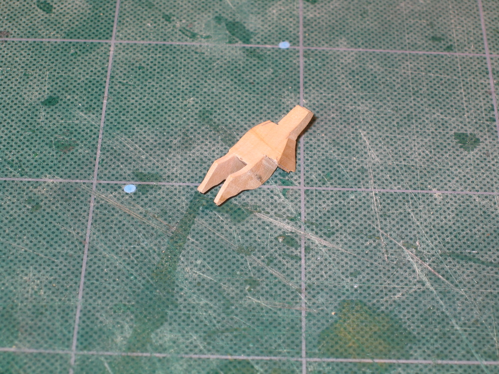
Now the front view was cut out which resulted in a blocky figure from which the actual carving would commence.
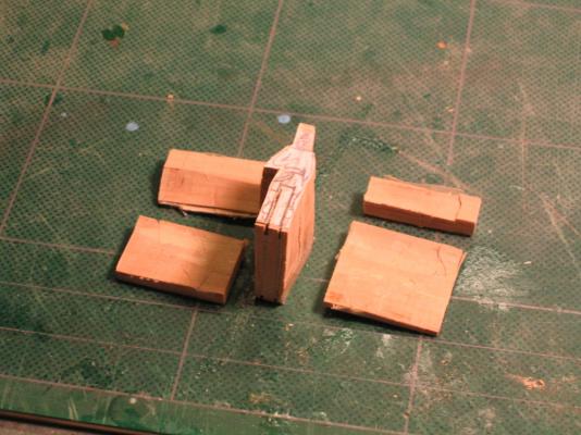

-
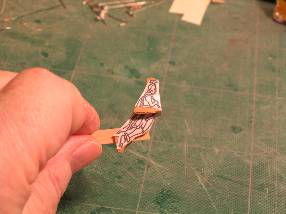
Using my scroll saw the side view was cut out and then reassembled with tape.

-
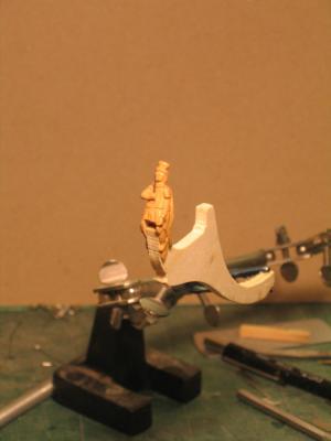
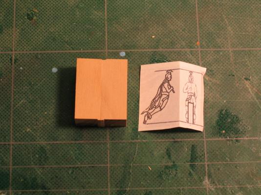
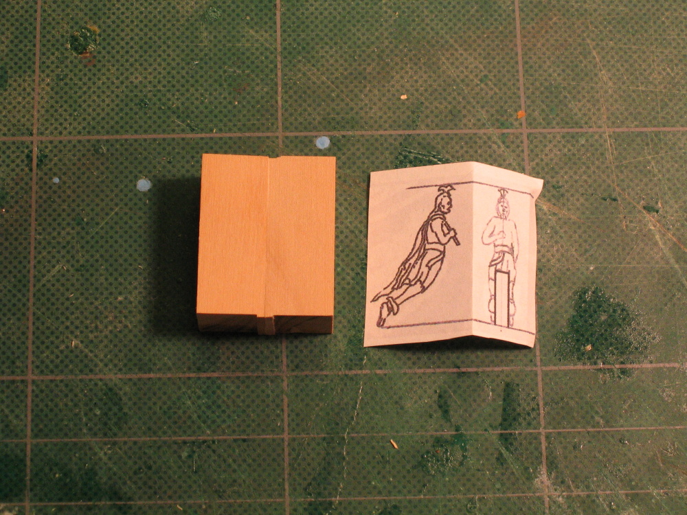
The Figurehead
Once more I was in an area I had never been before. I needed to carve a full three dimensional human figure. Heck, I can even draw a human figure let alone carve one. But like before, in for a penny, in for a pound. That and the fact the kit supplied figure won’t fit the scratch built stem. I was committed.
Following the Practicum I printed the side and front views of the figurehead and rubber cemented them to a block of wood.
-
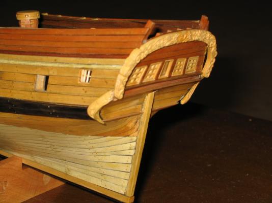
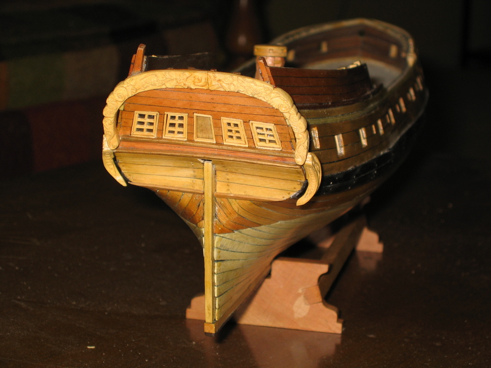
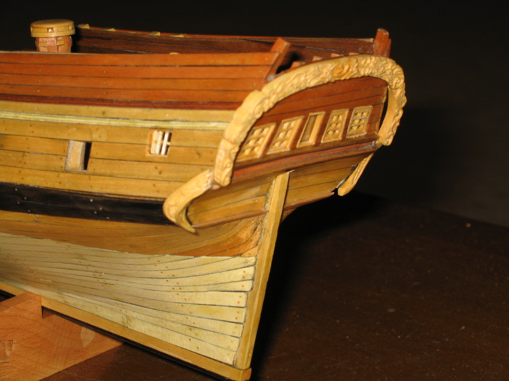
The stern and counter carvings were installed to the model

- KenW, Torrens and Duanelaker
-
3
-
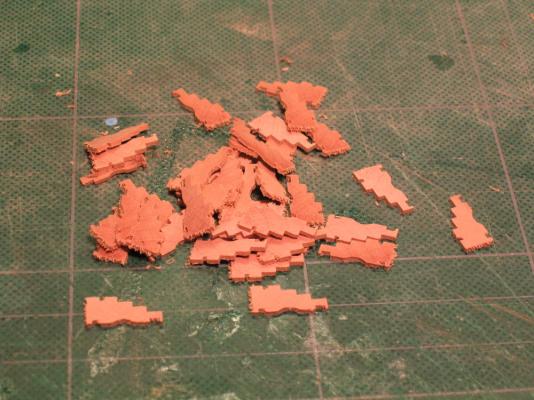
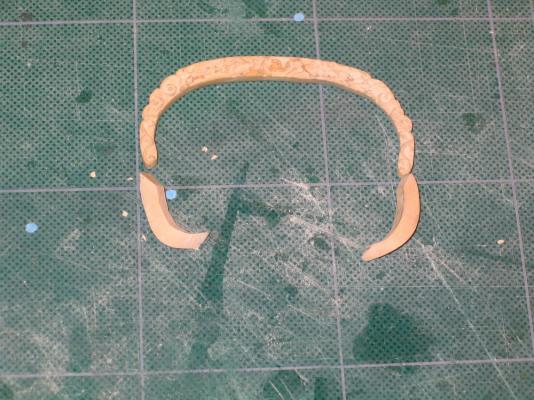
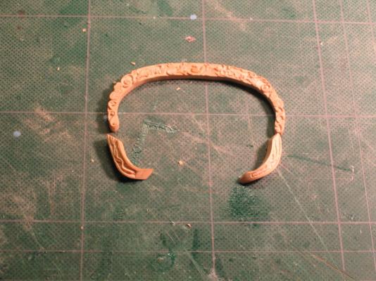
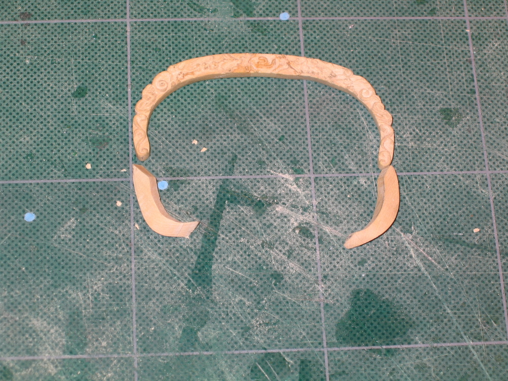
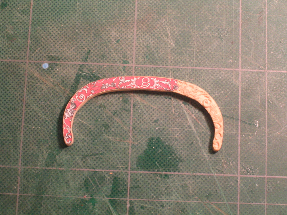
The Counter Carvings
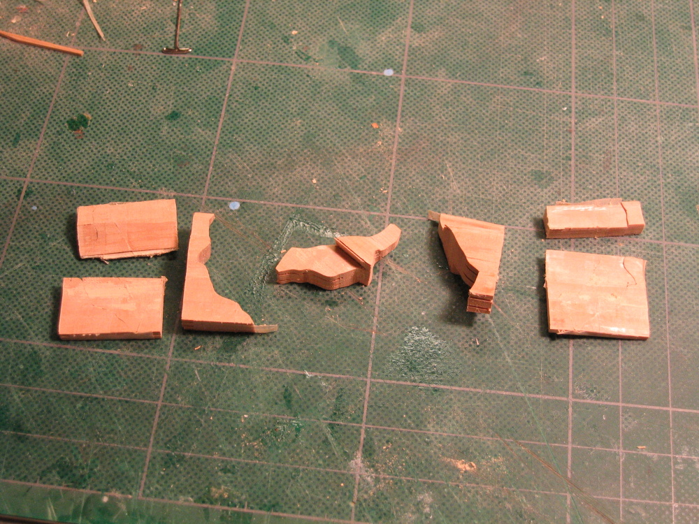
Mr. Hunt wanted to provide an alternative method of creating ornamentation using a clay product called Premo because these counter carvings use compound curves and are difficult to create in wood even for him. I didn't like the results he got with Premo as shown in the Practicum, so I chose the hard method – I would wood carve it.
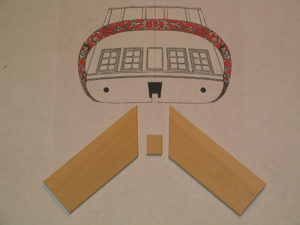
I made numerous attempts because there is no true view of this shape. Through trial and error and shear tenacity I final came up with the shape that appears to work and would fit to the model.
-
The carving commenced using the various burs, needle files and X-acto blades. For a first time carving the results were satisfactory to the novice eye. It didn't match the perfection of a skilled carving but it will do.

- goatfarmer11 and MEDDO
-
2
-
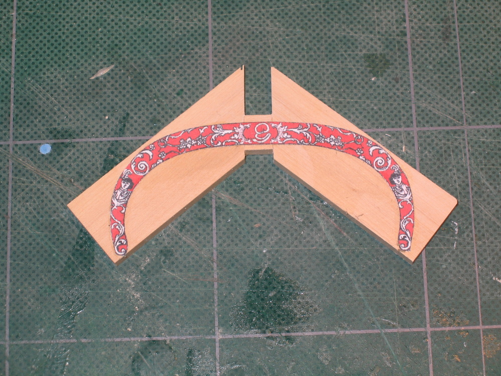
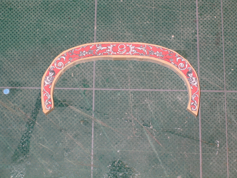
The three pieces were glued together tight. The template was cut out, and rubber cemented to the assembled pieces. The shape was cut out using my old Dremel scroll saw


-
-
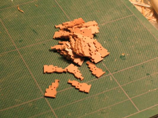
Mr. Hunt was very thoughtful and provided a color template. Anything in red was to be cut out. It made the carving easier to do. Because the carving is large and the HobbyMills wood package does not provide a piece of wood that width, the Practicum instructs the builder to use two pieces of 5/32” x ¾” wood stock and carve them separately in case “you mess up.” See the image from the practicum below.
-
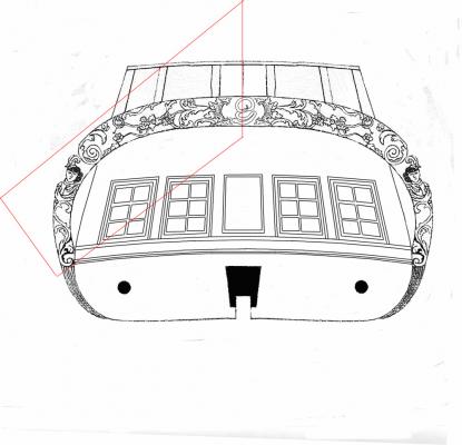
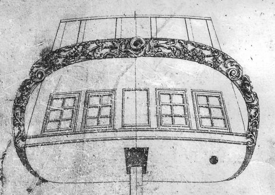
The Stern Carvings
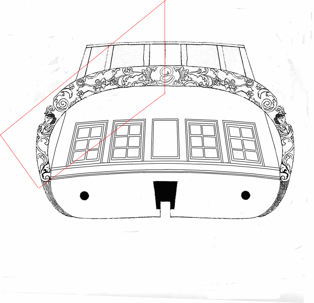
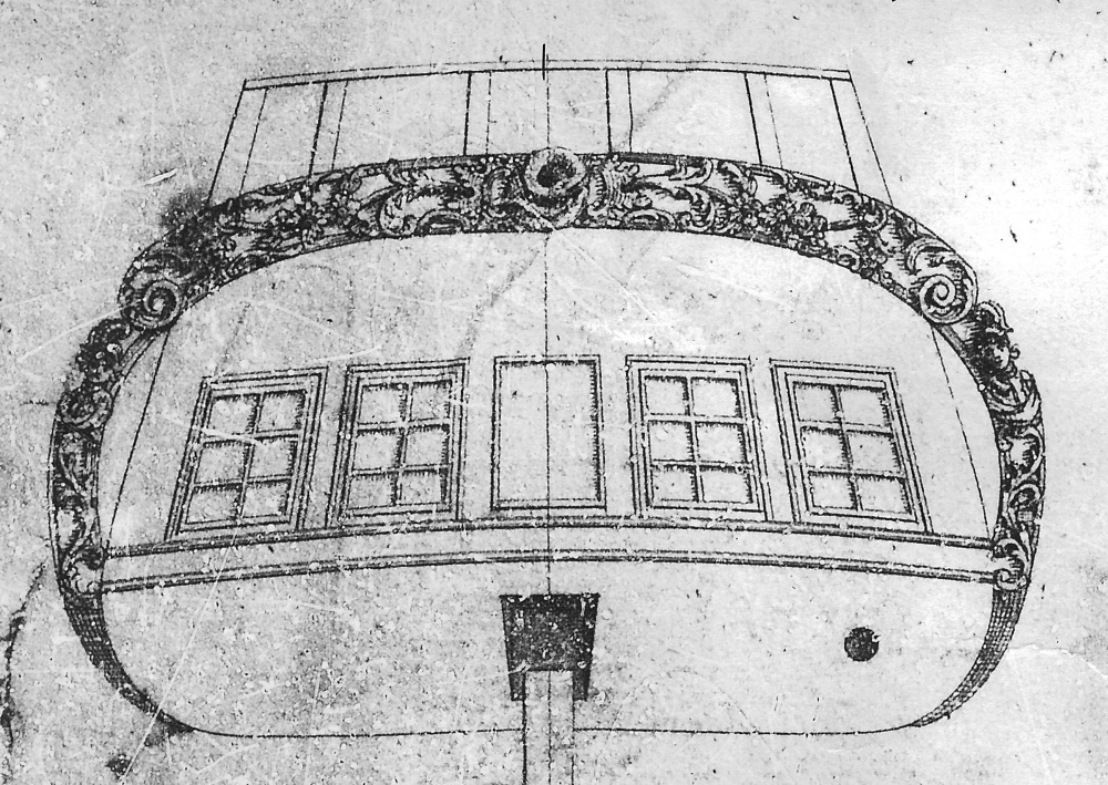
I have looked at a lot of rattlesnake models on the internet to see how the stern carvings were done. It appears no two are alike. They range from using the pre-cast metal “carving” the kits (MS and Mamoli) provide to simple or elaborate hand carvings. The practicum shows what the original British Admiralty draw looked like and the detail leaves something to be desired. Mr. Hunt made an admiral attempt to “clean up” the image but even he had difficulty with the snake image in the center of the carving. It is very difficult to discern the details. What he saw differs from what Mr. Hahn saw, which differs from what I saw. Since no can agree as what it really looked like, in the end I compromised a bit and used what I could carve.
-
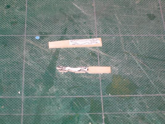
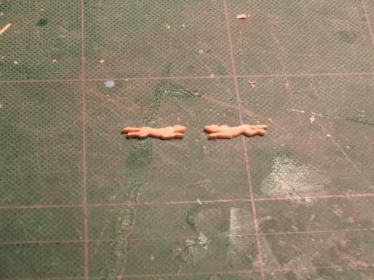
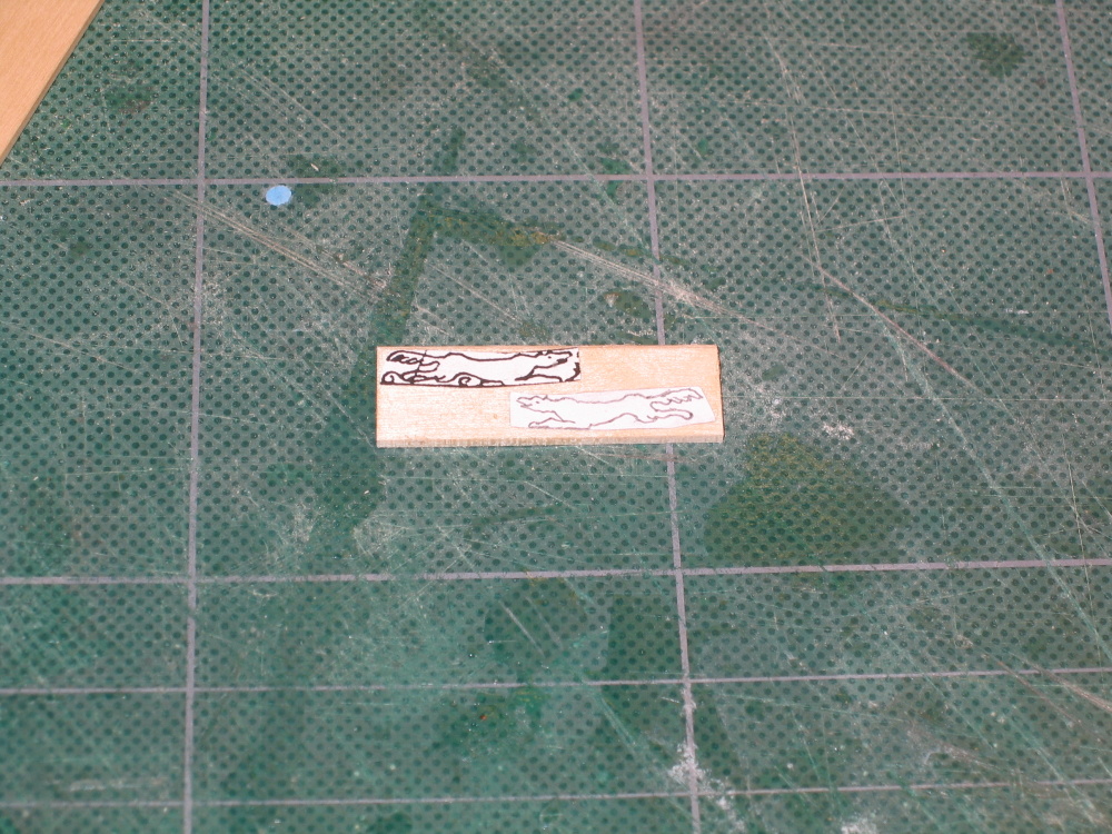
The two wolves were separated and with minimal effort using needle files and a fine chisel, I got what I assume is a satisfactory result.
- maddog33, KenW, goatfarmer11 and 1 other
-
4
-
The Carvings
Other than carving a canoe out of a piece of stick with a pocket knife when I was nine years old, I’ve never carved anything, let alone what I was about to attempt. The Practicum recommended that the builder get Bill Short’s book Carving ornamentation for Ship Models which I did. The Practicum also recommended that one should purchase a number of burs from Livesays Inc. for a rotary tool like the Dremel drill. This was almost mandatory as the burs are very fine and they are needed to make the fine cuts. I bought a few more than what the Practicum recommended:
Type mm Part No.
Ball Bur 0.50 18.1766G
Cone Bur 0.80 18.289G
Bud Bur 0.60 18.237G
Inverted Cone 0.60 18.537G
Mr. Hunt used a Turbo Carver but the Practicum advised against this purchase unless you are really into carving. As much as I like tools, I didn’t buy it.
The Stem Carvings
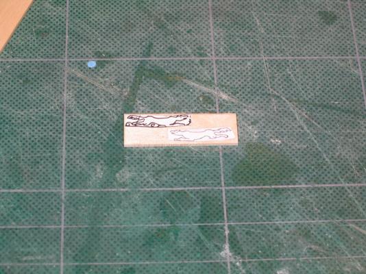
I suppose Mr. Hunt assumes that if the builder is going to carve the embellishments for the model, the builder must know how to carve because the first item the Practicum discusses is the stern carving. Since I’ve never done this before, I started with the stem carvings of the running wolves a much simpler challenge. As is the usual practice, the image was copied, cut, and rubber cemented to the stock wood. Because there is a wolf on either side of the model, the second one was reversed before printing.
-
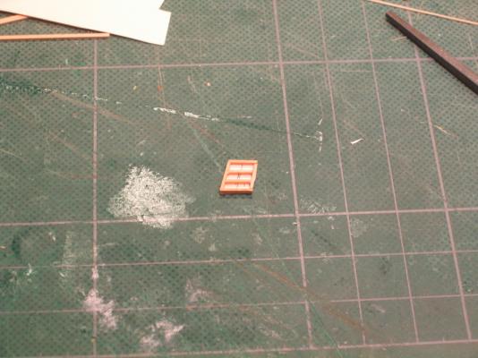
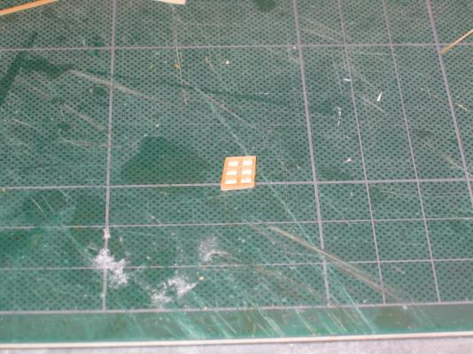
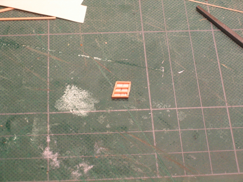
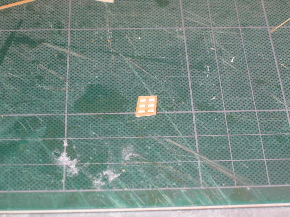
A template was made of each window showing the framework. The window frames were then constructed sandwich style like before. Place framework, add clear plastic insert, and add framework.

-
CHAPTER 6 –The Carvings
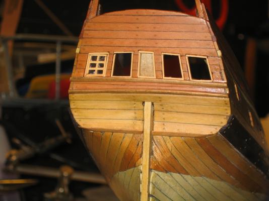
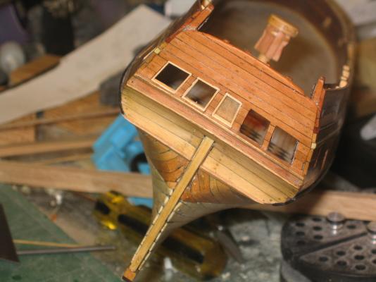
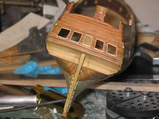
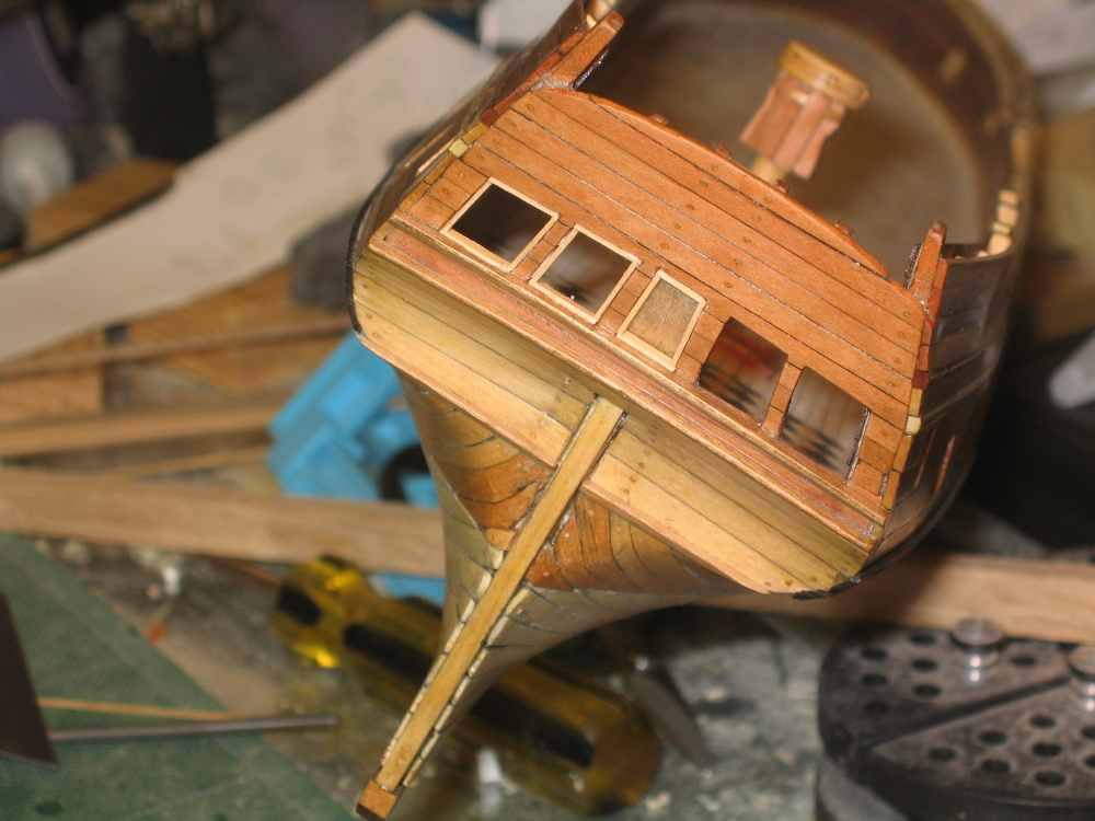
Transom and Side Stern Windows
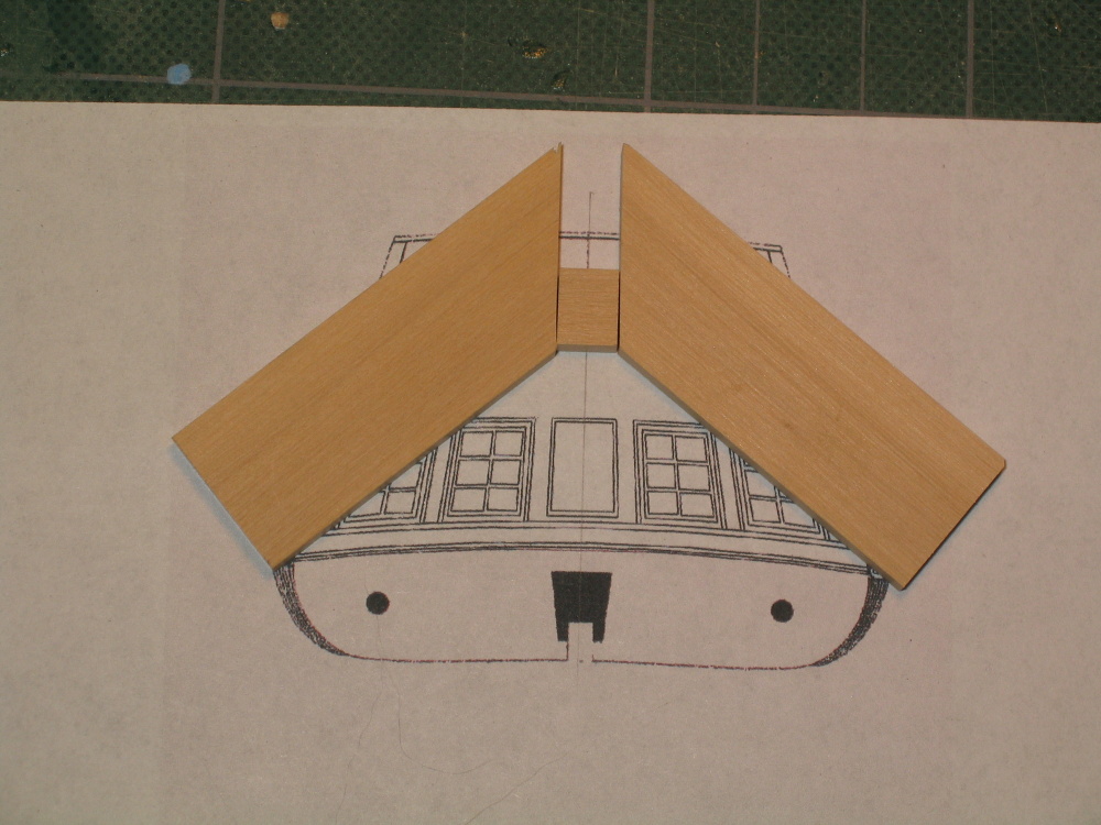
At this point the Practicum directs the builder to start the carvings. I looked at the boat and wondered why aren’t the transom and side stern windows being installed at this point? It would seem to be easier now than later when the carvings and interior stuff get installed. So once more I deviated from the Practicum.
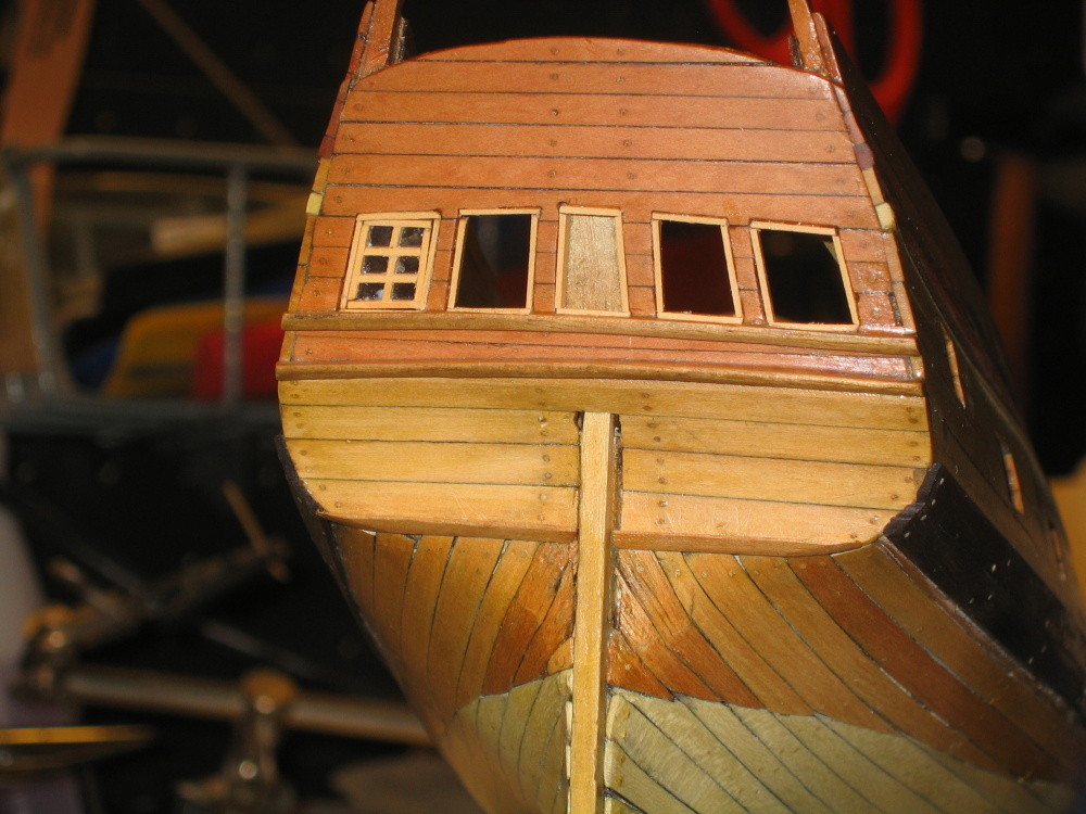
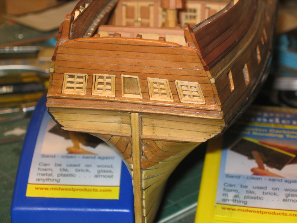
Looking at the transom, Mr. Hunt elected not to put in the center panel. All the models I saw including Mr. Hahn’s had the panel, so I decided that I would install the panel. It would have been easier when the window opening were first constructed, but now was not too late. Following the existing window lines the panel opening was drawn, drilled, cut out, and trimmed. Not knowing how the panel was constructed or how that construction would affect the completion of the interior as directed by the Practicum, I decided to use the 1/64” plywood for the panel face because it was so thin. I figured it wouldn’t affect the Practicum’s building process. Later on I saw one model maker use planks.
Looking at the Hahn model pictures, I saw that the windows and the panel had frames around their openings. The windows then had their own frames. The opening frames were constructed directly on the model. The panel plywood was cut to size to just cover the opening and glued to the interior.
-
Many thanks for the photos. Out of curiosity, you originally stated that "we used the rigging plan for the Rattlesnake as the model for the Eleanore's rig." What was the source used for the Rattlesnake rigging plan? Other than the rigging plan that Harold Hahn created for his model (based on the original British Admiralty drawings) the only other one I have found is in the book History of American Sailing Ships by Howard Chapelle.


Rattlesnake by JSGerson - FINISHED - Mamoli - 1:64 - Using Robert Hunt’s practicum
in - Kit build logs for subjects built from 1751 - 1800
Posted
The carriage trucks
To ensure the axles were good, I jumped ahead in the Practicum to create the carriage wheels otherwise known as trucks. They are made from a 5/32” dowel. Choose this dowel carefully; you want it as close to perfect as you can. Any imperfections in roundness will be exaggerated when sliced into trucks. Once again back to the tablesaw and 80 1/32” trucks were sliced off the dowel.