


Don
-
Posts
23 -
Joined
-
Last visited
About Don

- Birthday 08/20/1962
Recent Profile Visitors
3,457 profile views


-

Does anyone have the instructions for the Aeropiccola sectioned Essex ?
Don replied to Gnome's topic in Wood ship model kits
I believe it is the same scale as the Aeropiccola Essex full ship model, the references that I found are 1:70 and the same overall height of both the section and full ship models are about 29 inches. Don -
 catopower reacted to a post in a topic:
Does anyone have the instructions for the Aeropiccola sectioned Essex ?
catopower reacted to a post in a topic:
Does anyone have the instructions for the Aeropiccola sectioned Essex ?
-
Gregory reacted to a post in a topic:
Does anyone have the instructions for the Aeropiccola sectioned Essex ?
-
Does anyone have the instructions for the Aeropiccola sectioned Essex ?
Don replied to Gnome's topic in Wood ship model kits
Yes the kit did come with the plans, there were 2 sheets, unfortunately I tossed everything awhile back. Even if a piece or two is missing from a sheet I am sure you could make a replacement easy enough. There is a build log for the cross section here on MSW by Heronguy, but he has not been active since 2023, it does show both sheets of plans. Also Aeropiccola made a kit of the full ship in the same scale. Trippwj has a build log going for that, he is still active on the forum. You probably could build the model using those 2 sources. Another good source would be mtbediz scratch build of the Essex he use Aeropiccola plans as a starting point and turned it into fantastic looking model, he is very active on the forum. Really is a easy build. Looking back at Heronguy log kind of refreshed my memory. I basically built everything to fit as I worked my way up from the bottom using the plans as a reference of where approxiimately everything went. Just make sure the decks and gun ports work out so the cannons fit correctly in the ports. I remade some parts to get everything to fit and align etc. at that time I only had hand tools to work with. Everything for this model can be very easily made with just a few hand tools. With these old kits you have to adjust and fit as you go anyhow, as they are not the most accurate kits, but mine did make a good looking model even though not the most historical accurate. You could also use some references and add to the basic kit, that would really inhance it, plenty of build logs to help with that. Also you can google to see if there are any photos of the plans by Aeropiccola, there should not be any copywright issues as this company has been out of buisness for a long time. Lots of info available here on MSW, if you decide to give it a try start a build log and ask questions I am sure you will get all the help you need. Don -
Does anyone have the instructions for the Aeropiccola sectioned Essex ?
Don replied to Gnome's topic in Wood ship model kits
I built this model about 35 years ago. If I remember correctly I did not use any manual just the plans. It was straight forward and turned into a very nice looking model. Not the most historically accurate but decent to display. It is the only model I haven't given away. So if you have the plans you are good to go. Start a build log, I am sure if you have questions you will get answers and be able to complete it model. Don -
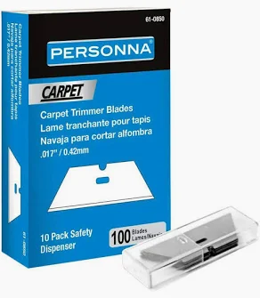
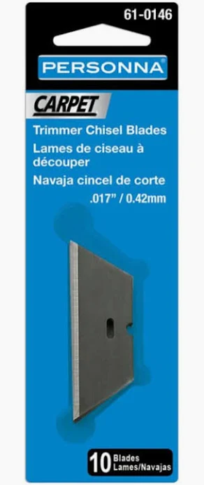
The Ultimation Slicer blades are available at Home Depot and I am sure Lowes and others. They are Personna Carpet Trimmer Chisel Blades No. 61-0146 for 10 count. They also have a 100 pack 61-0850. These are single edge blades not beveled on both sides just one. At least in my area; the 10 pack in about $3.50 and the 100 pack is about $18.00. I live outside of Toledo, Ohio in a rural area, so when I ordered slicer I just ordered replacement blades from him. I didn't feel like the 30 minute drive there to pick some up . When I am in the area I will probably pick up some, just so I don't feel like I need to use a dull blade to save my supply. They seem to last awhile, so a hundred pack would probably last a life time.
-
Canute reacted to a post in a topic:
Scalpel handles...
-
mtaylor reacted to a post in a topic:
Scalpel handles...
-
Ryland Craze reacted to a post in a topic:
Scalpel handles...
-
thibaultron reacted to a post in a topic:
Scalpel handles...
-
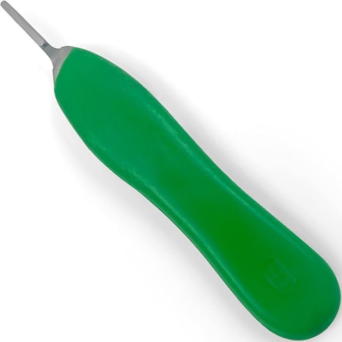
I use this type of handle. I do not like the flat metal ones either Look for a good quality so that the blades hold solid but can still get them off and on Don
-
GrandpaPhil reacted to a post in a topic:
CV-59 USS Forrestal Carrier
-
Canute reacted to a post in a topic:
CV-59 USS Forrestal Carrier
-
mtaylor reacted to a post in a topic:
CV-59 USS Forrestal Carrier
-
GZM2023 reacted to a post in a topic:
CV-59 USS Forrestal Carrier
-
CV-59 USS Forrestal Carrier
Don replied to GZM2023's topic in Building, Framing, Planking and plating a ships hull and deck
Not a problem just PM (private message available through the forum) May I make a couple of suggestions which I think will help you out a lot. First start a log of your build even though you are just starting the CAD work, you will find that a lot of members will follow even if they don't comment on everything you post. Pictures are a great help when trying to help someone so post away. Many will comment if they have some input, which is a great help. You will find that this forum has some of the finest model ship builders in the world and there is a wealth of knowledge available. I know I shouldn't talk, I have not keep up my log, but I do plan on being more active now that I retired. It may take me a bit to get everything I am doing updated, I just retired at the end of 2023 and retirement is definitely a change. Also it would help if you added your location to your profile. This will help when suggestions are made about materials, tools etc. Even within the states not everything is available everywhere. As an example, I live in an area where hardwood is readily available but Alaskan Cedar is not I have to source that which is more expensive and not just a run down the road. Even though this model is gigantic in size the scale is still relatively small compared to some scales being used here, 1:64 and 1:48 are very common, which are larger than what you are working in. All the stuff that gets added is what makes your project come alive. With a model size of over 14' every area will need to be as detailed as possible. It will be hard to take the whole model in at once so people will view areas, so each area essentially becomes a model. This is where a log will help you out, the members here can offer many tips, tricks etc. What one person didn't think of someone else will. Many brains work better than one in this case. As I am sure you probably already figured out is that you cannot have enough source material and this will be an ongoing process. I found detailed pictures are of great value, you cannot have enough of them. I am lucky the sister ship the USS Salem CA 139 is a museum ship located in Boston. So for me the net is loaded with video and images that are of great value to me. Do a few mockups to see if it will work for you. Doesn't have to be precise or a lot, just a few bulkheads for example will give you a feel if the materials you plan on using will work for you. Remember what worked for me may not work for you. Everybody has different tools at their disposal. It will come together, have to start somewhere, solve each problem as they come up. That's what makes it fun. Don -
CV-59 USS Forrestal Carrier
Don replied to GZM2023's topic in Building, Framing, Planking and plating a ships hull and deck
Its been awhile ago since I made the frame work, but I think it was baltic birch plywood 3/8" probably maybe 1/2". Not sure where you are located but in my area I could only get 5'x5' sheets so I had to splice the length together. I basically used plywood gusset plates to join the sections together. Baltic birch plywood is fairly straight doesn't have voids and has more plies than standard plywood, it is used in cabinet work. The down side is, it is very hard to sand and shape but stable. The bulkheads I think I used 1/4" reason less sanding and weight. I do some cabinet work from time to time and good plywood is getting harder to find it is also much more expensive than when I got mine. Look for a place that caters to cabinet makers. With the length that you are building about 14' deflection will be an issue no matter what you use, like I said good plywood is hard to get. You will have to brace it in some sort of building board or jig. The good thing is that you can screw it almost anywhere everything will get covered. Just remember as you start to plank it and get the hull covered don't cover up where you screwed it down. You have to get the thing loose from the building board and or jigs you are using to hold it straight. The cruiser I am building has sheer to the deck which you aircraft carrier does not so that will be easier to get a nice level surface. Spend a lot of time at the beginning to get everything straight, level and symmetrical etc. it will save you a ton of time latter. The cruiser hull is sleek and solid, as you know an aircraft carrier hull towards the deck is anything but sleek. You will have to work out how much you want to leave open, work in all the access decks, weapon areas etc. as you get closer to the deck. I started mine upside down and planked toward the deck fairly straight forward. With an aircraft carrier and flight deck along with hull openings everywhere you will have to be more more creative. Don -
CV-59 USS Forrestal Carrier
Don replied to GZM2023's topic in Building, Framing, Planking and plating a ships hull and deck
You are on the right track, I see what you are getting at. I really don't think you need all those stringers or any at all for that matter, but that is a matter of choice on how you want to build it. I think it would work out ok. On an aircraft carrier their shape is not the same as most naval ships, so I think it will be a little harder, but doable. I am building a model of a heavy cruiser USS Des Moines CA 134 I have a log started, but have not added to it in a long time. Was building this for my dad, he served on the ship for a couple of years in 1958-59. He passed away suddenly and have not worked on it since, but I am going to get it out of mothballs sometime soon, my kids want me to finish it. I have since retired and have more time now (I hope). Anyway, the scale is not the same but close 1:96. It is large almost 8 feet and it is father along than the log. It is planked, filled in and sanded now I am adding simulated plating and armor belts etc. I built it like most POB, center keel or former, bulkheads and planked. I can tell you this much with a ship of that size there will be a lot of construction material to get it all framed out, it will start getting heavy quickly. The more frames you add the easier it will be to fair up and to get it planked. No matter how much CAD work you start with some frames will not be right so be prepared to do some sanding or adding material, or just making a new one. I started mine out with drawings in CAD and added bulkheads so the planking didn't have to span real large distance. I really should have added more but it was getting heavy enough as is. The bulkheads, center and deck are plywood, the planking is some poplar and beech I had laying around. If I had to do it over I would have used some thin plywood (like 1/8") for planking just to control the expansion contraction issues with natural wood. I also used a pneumatic pin nailer and lots of glue to attach the planks lots of them. Much faster and easier than glue and clamps. Just make sure the countersink far enough for sanding. Make sure it is centered down the middle, that's why I stated with the center former. I used a laser level etc. and screw it right to a building board and worked out from there. Be prepared to do lots of sanding and filling and don't rush that job. you want your hull to be the shape it supposed to be both sides, you will notice waves and dips as you move along. That's were all the sanding and filling comes into play and you swear you will never finish. There will be a time where you say good enough. You can check out my log. It is in my signature. Don -
Take some accurate measurements as has been mentioned and take a look at McMaster-Carr website. Don
-
For wood to wood any yellow glue will work, Titebond or Elmers I found work equally well for model work. Woodworking is were the different types are used for various applications. Elmers white glue will hold but is harder to get the initial tack or grab, clamping is more important. Yellow glue has good initial grab and a lot of times you can get away without any clamping. I don't use much CA for wood to wood bonding but I do use them together sometimes. A small amount of CA with yellow or white glue for the rest of the joint. The small dot of CA acts as a clamp while the other glue sets up. The bond strength does not come frm the CA. Don
- 85 replies
-
- 4
-
-
- Lowell Grand Banks Dory
- First Build
- (and 2 more)
-
Making and using a draw plate
Don replied to Don Case's topic in Modeling tools and Workshop Equipment
I would take a look at the Byrne's draw plate, it's a good price for the quality of the product. Put it this way, my son has his own machine shop with full CNC machine capabilities and I still bought one from Jim. It was just not worth it to make my own. The reason for this I would only make only one and I am sure he makes them in batches which is far more economical. Also his is nicely hardened and should stay sharp for a long time There lots of stuff that may be cheaper and easier to make yourself than try to find commercially, this I just don't think is one of them. Don F -
I ordered the last 3 books that I wanted from Seawatch about 2 weeks ago. Received all 3 in about 10 days could not believe I received them that quickly. Wasn't really expecting them until sometime in February. I guess I was lucky, had stuff bounce around the postal system for a month. Don
-
As far as I know there are no programs that will give you a 100% conversion without some manual touch up. I found it was easier to scan what you want insert the scan directly into CAD, scale it, and trace over the underlay. On bulkheads and frames etc you only have to trace half and mirror the other side. This way you can correct any errors in the original. Don
-
Doug, Speeds and feeds for milling whether manual or CNC can be tricky. It depends on many factors material, bit size, spindle speed, feed rate and the bit type (carbide, HSS, number of flutes) whether drill, end mill etc. and chip clearance. Check out some speed and feed calculators online to give you some ideas. The the short answer for the slower rpm is you can use HSS bits to cut hard material such as stainless or tool steel. If you switch to a carbide bit you can increase your spindle speed and feed rate without burning up the bit and get a good finish. In our hobby work we usually work with softer materials such as wood, brass, plastic etc. so the slower speeds aren't as important. You also have to keep in mind many of these calculators may assume you are using a coolant which you will not be using. A easy visual of this is using a hand router. Move the router to fast it starts tearing out and leaves a rough surface, to fast and you burn the wood and bit. Keep in mind we are doing this for a hobby to have fun. In the end you will probably use the higher end of the spindle speed with some carbide bits and adjust you feed rate to match. Don
-
Doug, EMC2 and Linux are open source software, you should be able to upgrade to a newer version without any cost. I am not real familiar with either thou but I am sure an Internet search would give you all the info needed. I use mach3 for my control software which is windows based and very popular with hobby and small shops. The important thing about both programs is they are based on old hardware platforms specifically the 25 pin parallel port. An old computer with the parallel port on board is an advantage. If you use a newer computer with no parallel port you will need to convert the USB signal to pulse signal for the 25 pin parallel port that goes to the stepper drivers. The timing of these signals is what allows you to control direction and speed in all directions at the same time. You would think that it would as easy as using an USB to parallel converter but it's not. You need special converter or a separate breakout board (such as smooth stepper). Also just sticking in a parallel card in the computer is a hit and miss, I don't know about the new Linux platforms but the new Windows OS do not support parallel ports the way the old OS did. Whether you have an box that plugs directly into an USB or an Ethernet port all of the stuff I just mentioned is built into the box. From that hardware, whether in a separate box or built into a computer, this is what you connect your stepper cables to. You do not need a new processor to run these programs. I use an old Pentium 4 with Windows XP that is over 10 years old. Will I have to eventually upgrade, yes but not until this computer dies. The main reason is that I would have to buy a USB motion control breakout box and reload and setup up the software. Yes you can use a CNC machine manually. There are a number of ways: handles on the stepper shaft,. keyboard, joystick, and a pendant (MPG (manual pulse generator)). A pendant is the easiest. All the axis, speeds, steps etc. can be controlled by this hand held unit. What also is important is the spindle speed. Getting something up to 10000 rpm is nice especially since you will be using smaller cutters. I should say I don't own the Sherline I have a Taig CNC mill, but all these hobby type CNC machine are all basically the same. They use steppers, stepper drivers, control software (almost alway EMC2 or mach3), and a PC. You also need software to draw you part and software to generate g-code. Note Fusion is free for non commercial use. I am by no means an expert. My son has his own small engineering and CNC manufacturing business, so when he needs the extra help I operate one of the large mills (these are not hobby mill but the principle is the same) so this gives me some practice at what not to do. If I get in trouble I just find him that's the nice thing about being free help, but I have learned a lot by helping and watching him trouble shot. Don