DONATION DRIVE - SUPPORT MSW - DO YOUR PART TO KEEP THIS GREAT FORUM GOING!
×


JSGerson
-
Posts
2,632 -
Joined
-
Last visited
Content Type
Profiles
Forums
Gallery
Events
Everything posted by JSGerson
-
 Before I added the planks, the edge of the bulwarks had to be finished so that the rails by the gangplanks could be installed. A piece of swiss pear wood was installed in the end of the bulwark to provide the finished look. The planking was then installed. After the pictures below were taken, removed them and replaced them with a wider piece.
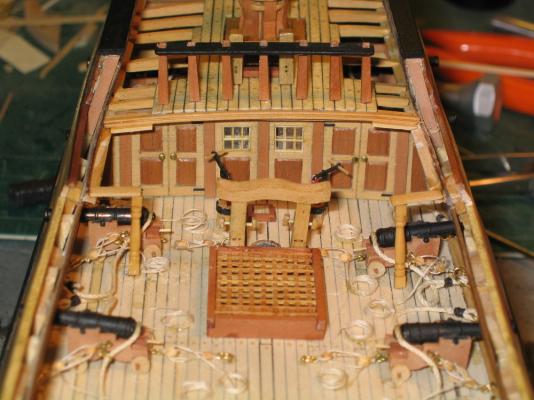
- 974 replies
-
- 2
-

-
- rattlesnake
- mamoli
- (and 1 more)
-
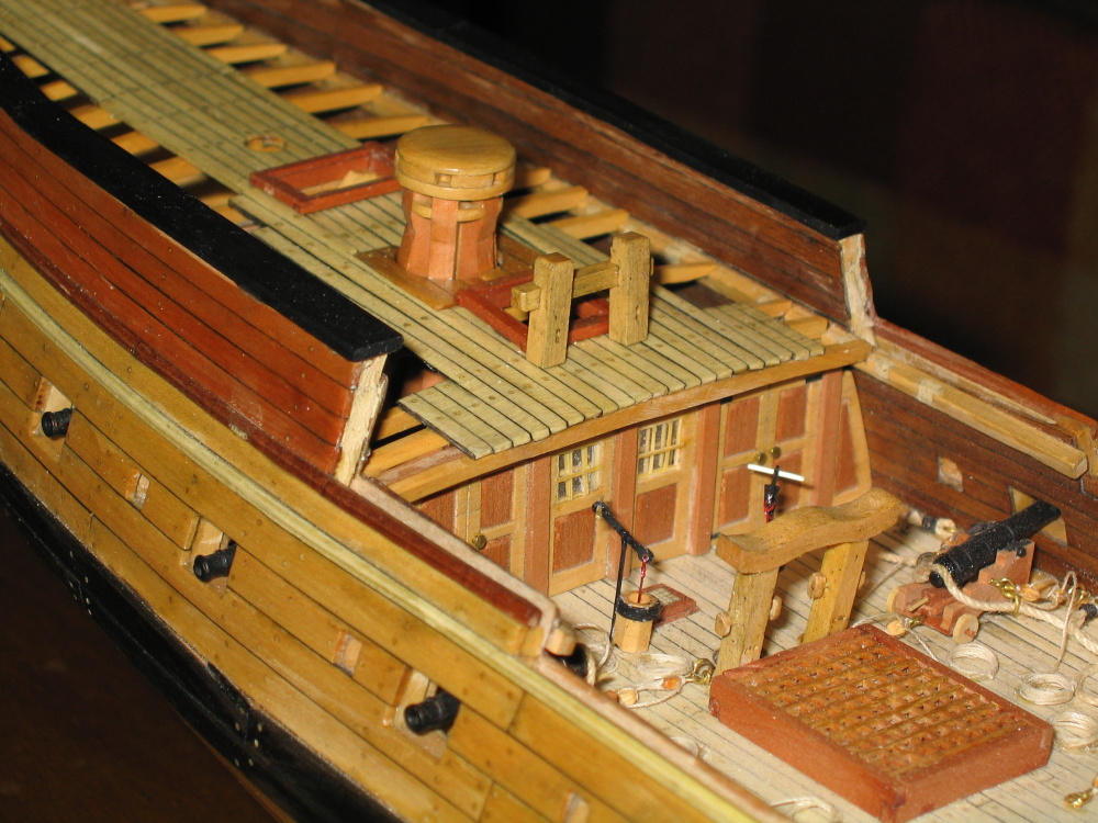
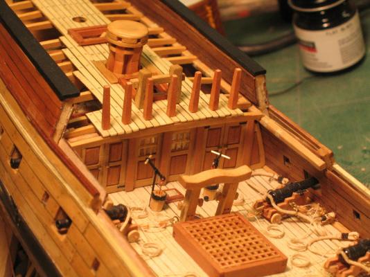
Building the gangplank support looked pretty simple in the Practicum, but it gave me fits in practice. First there is a piece of 1/32” x 3/32” boxwood that goes across the quarterdeck from one deck clamp to the other. It appears that Mr. Hunt placed it on top of the quarterdeck at the forward edge. As I interpreted Mr. Hahn’s plans this piece is the edge piece. So instead of placing on the deck, I placed it on the edge of the deck. But just to fancy it up a bit, before I glued it into place, I cut a fine 1/64” deep groove with the Brynes saw with my thinnest blade. Then I gave the groove a slight V-profile using a V-needle file. The piece was then given a curve to match the deck. The gangplank was supported on the outer edge by the deck clamp and on the inner edge by a stanchion. A beam ran between this stanchion and the deck clamp and another piece was attached to the first quarterdeck beam to form a ledge for the planking to sit on. Note: I believe there is a typo in the Practicum. On page 73 just under the picture P8.1.11-8, the Practicum calls for 1/32” x 1/32” boxwood for the quarterdeck ledge. First 1/32” x 1/32” boxwood is not supplied with the wood package and second 1/32” x 3/32” boxwood works much better. A piece of 1/32” x 3/32” boxwood of proper length was glued to the top of each stanchion and then placed and glued into position. Finding that position took a bit of trial and error. Everything had to line up.
-
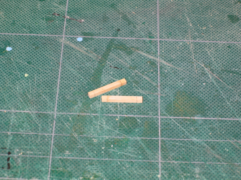
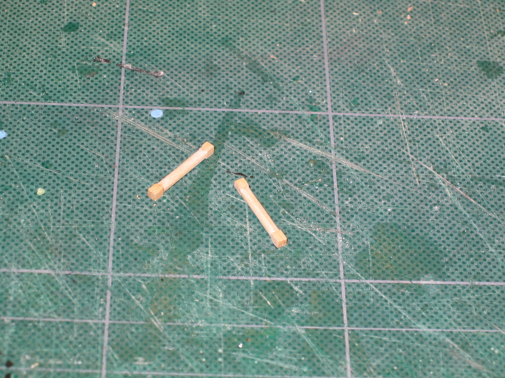
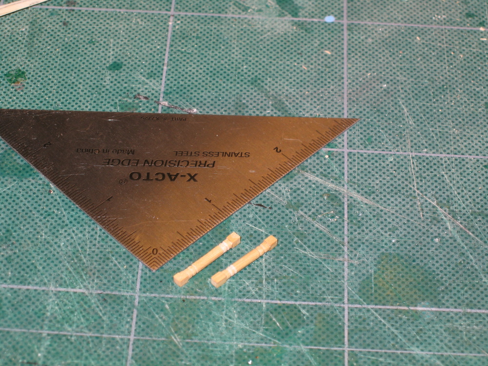
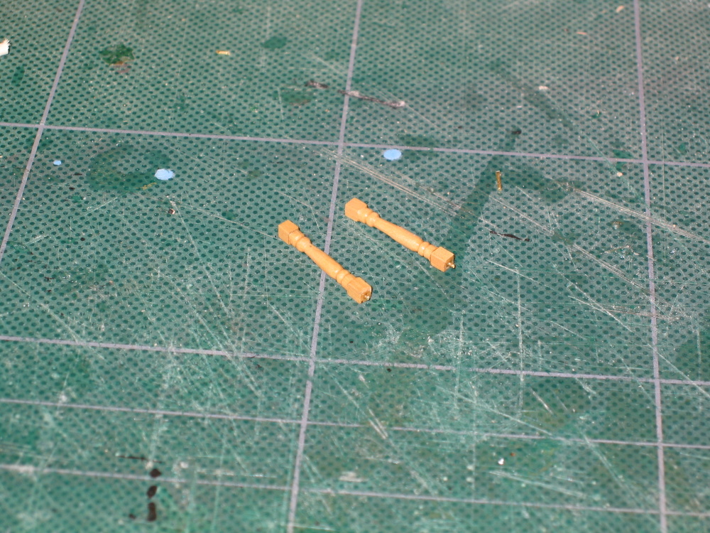
Fixed Gangways Coming off of the quarterdeck is a small deck on each side called a gangway. The gangway was a permanent structure and was slightly lower than the quarterdeck itself. In some models I have seen, the gangway is extended from the quarterdeck to the foredeck. The Mamoli kit does this and I believe the Model Shipways does as well. The Hahn model does not. If the HobbyMills wood package continues to be true to the Practicum (which for the most part it is) then there is probable not enough Holly planking for extended gangplanks if I decided to add them. Hey, this is my first wooden three masted sailing ship, I’m not ready to wing a large model design change so I’ll stick to the Practicum…for the most part. There are two stanchions on each gangplank, a lower and an upper; both are fancy pieces of stock that would typically be turned on a lathe, albeit a very tiny lathe. These however, were carved by hand and were relatively easy to do. Following the instructions of the Practicum I think the lower stanchions worked out pretty good.
-
The Practicum called for the rail to be 2 1/8” in length but based on Hahn’s deck plan, and verified on my model, I found that the length should be 1 15/16”. Notches were then cut into the aft side of the rail one by one verifying each position in turn and finally glued into place.

-
At this point, it seems to me it would have been the perfect opportunity to create the belay pin holes in the rail. Why the Practicum does not do this is a mystery at this point. I did not realize the rail had the belay pins until I looked over the plans that came with the kit. I was paying too much attention to them since I wasn’t following them. Marching along oblivious to the miss opportunity, masking tape was used to lay out a straight line on the quarterdeck and the seven stanchion position marked. The stanchions were then put into position.
-
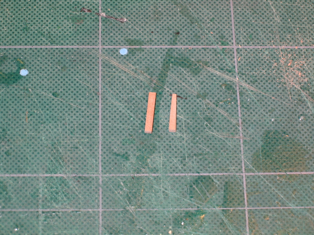
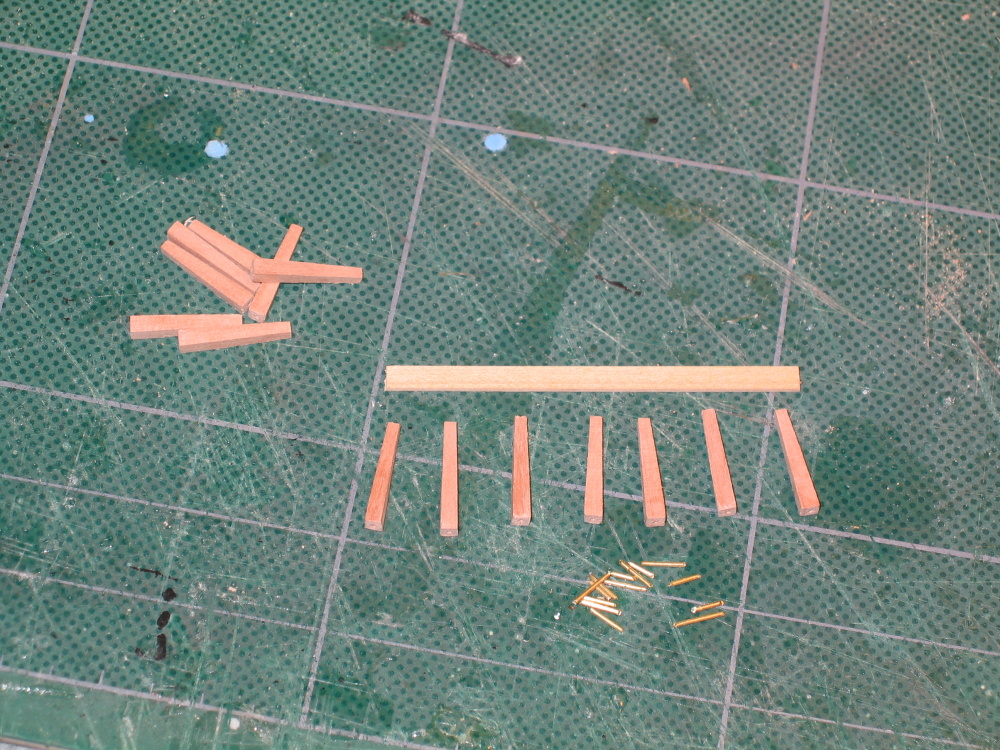
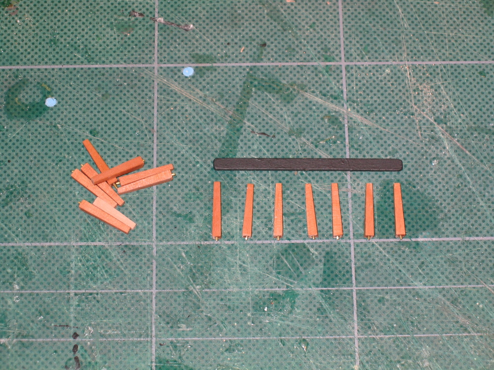
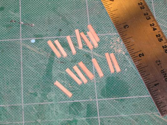
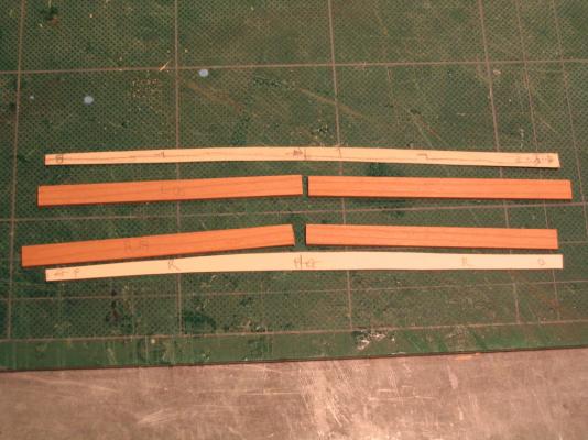
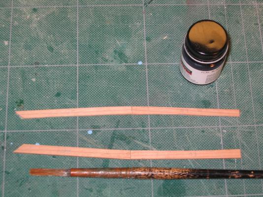
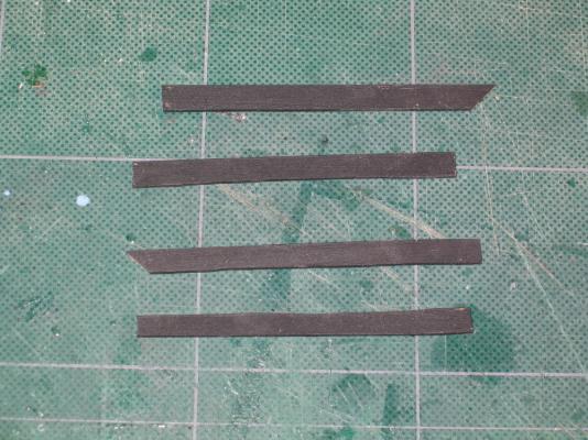
Quarterdeck Fore Rail The fore rails at the forward edge of the quarterdeck are made from seven 3/32" square swiss pear stanchions and the top is made from 1/32" x 1/8" stock stained black. Mr. Hunt stated in the Practicum that he later realized that this dimension of stock was not figured into the wood package. After verifying that my wood package did not contain the specified wood stock, I informed HobbyMills so that hopefully future packages would contain it. Why this was not brought to HobbyMills’ attention earlier is anyone’s guess. The Practicum went on to state that the shapes could be easily created from 1/32" x 1/4" boxwood and 3/32" x 1/4" swiss pear trimmed down from stock. 14 pieces of 3/32" square swiss pear stock were cut to a length. They were shaped into the truncated 4-sided pyramid stanchions. Pins were inserted and glued into the bottom of each stanchion for added strength when attached to the deck. Seven of these pieces were aside for future use for the forecastle rails.


-
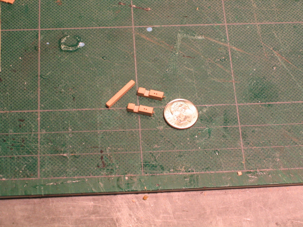
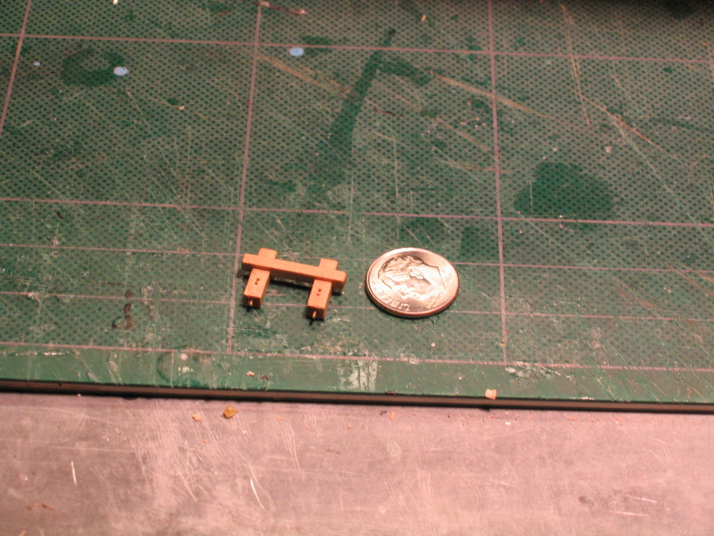
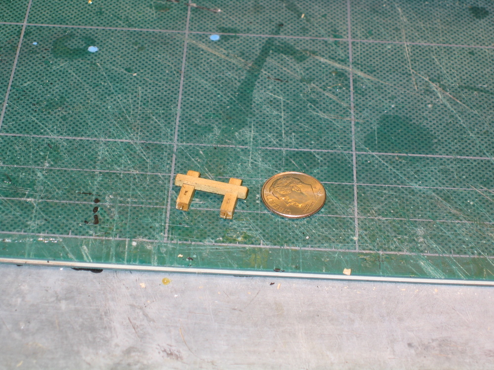
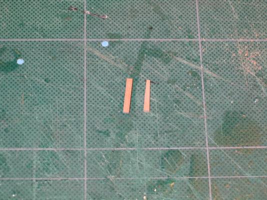
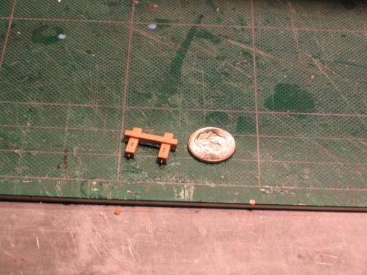
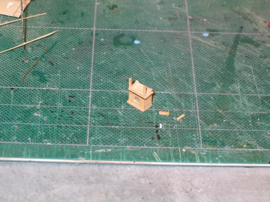
Fore Brace Bitts The fore brace bit in contrast to the binnacle is quite simple – three piece of wood notched and glued together.


- 974 replies
-
- 2
-
-
- rattlesnake
- mamoli
- (and 1 more)
-
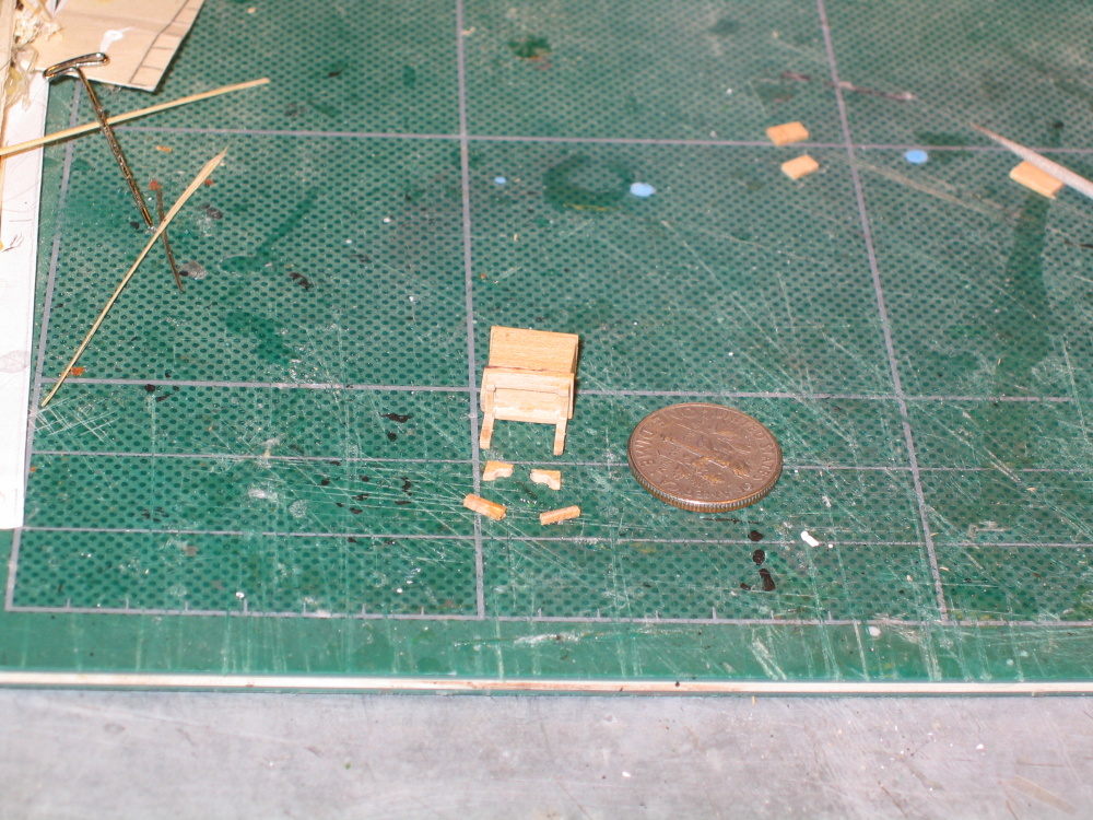
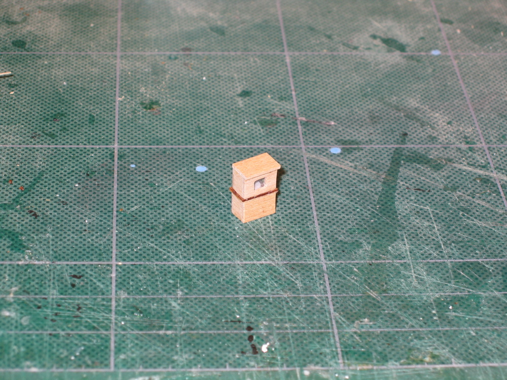
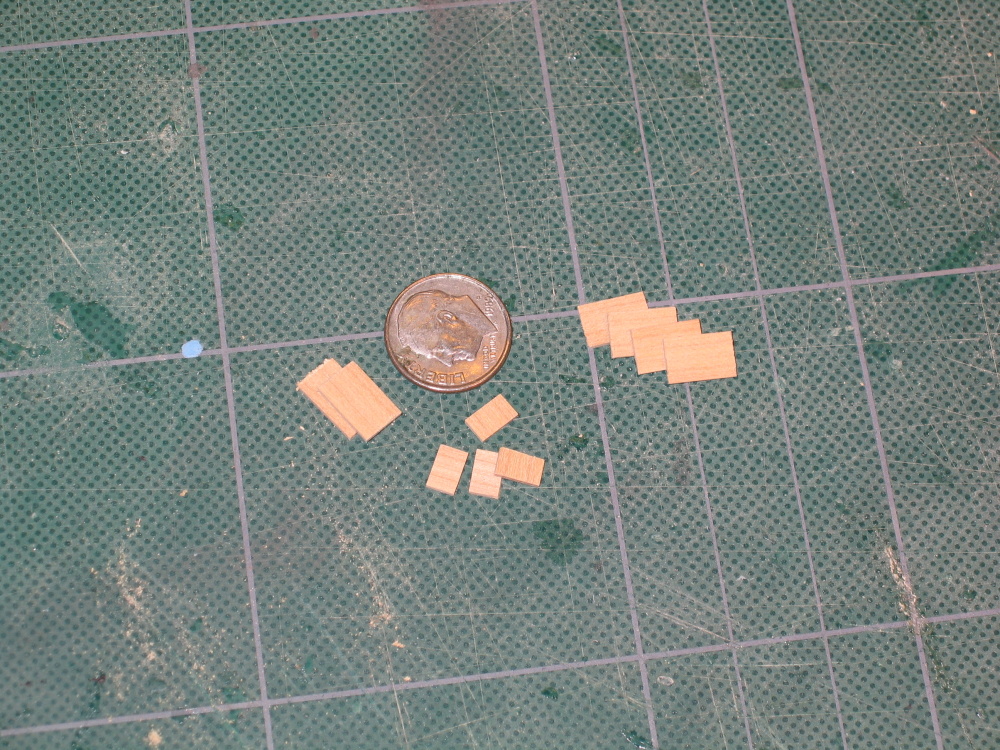
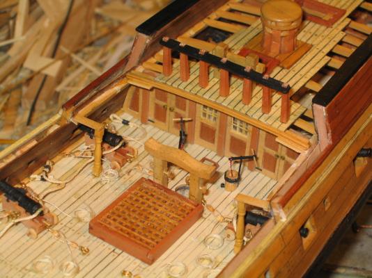
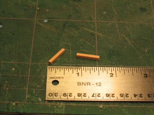
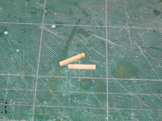
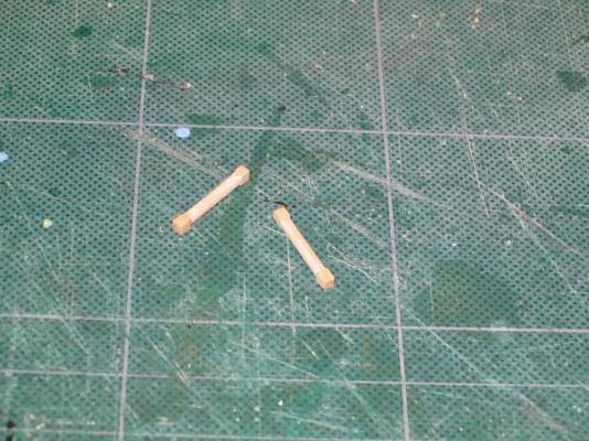
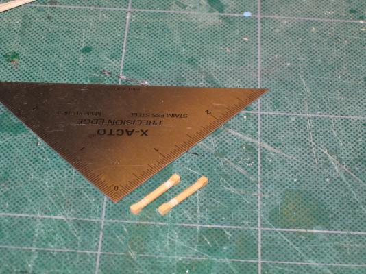
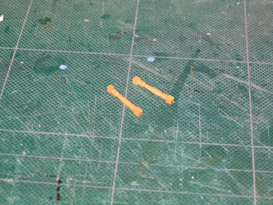
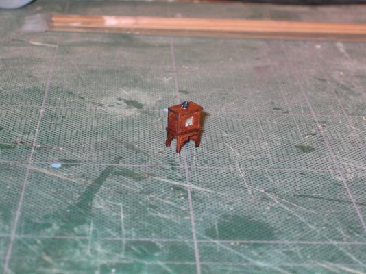
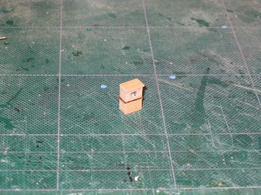
Looking at the Hahn’s plans and the photo of Hahn’s model (which I believe you need approval to print, which I don’t have) the legs are supported with some corner pieces. So I carved some with some needle files. Additionally I added the little black chimney on top. A little bit of stain and it worked out fine. This won’t be installed on the model until latter due to its delicate nature. As it turned out, you really can’t look into the binnacle window to see the interior, but I know it’s there.
-
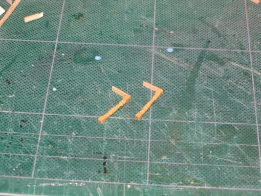
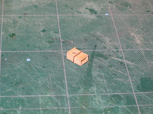
It was time to create the binnacle legs and they were fragile. Using the Byrnes table saw cuts were made in the bottom box. However in the process of removing the excess wood, I broke two of the legs.
- 974 replies
-
- 1
-
-
- rattlesnake
- mamoli
- (and 1 more)
-
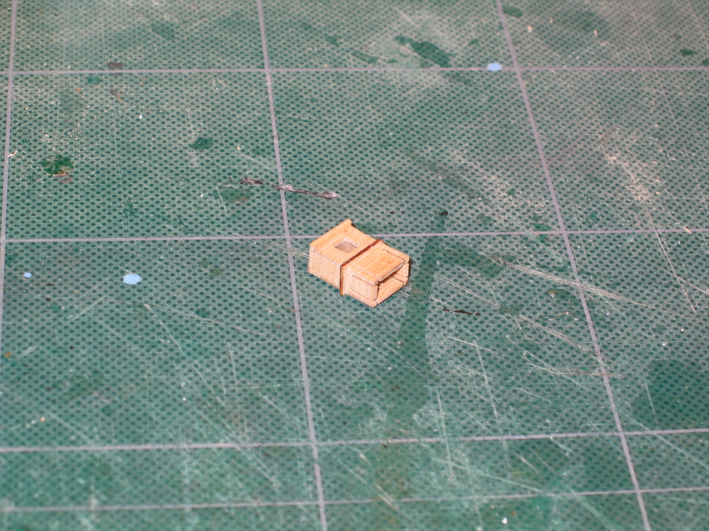
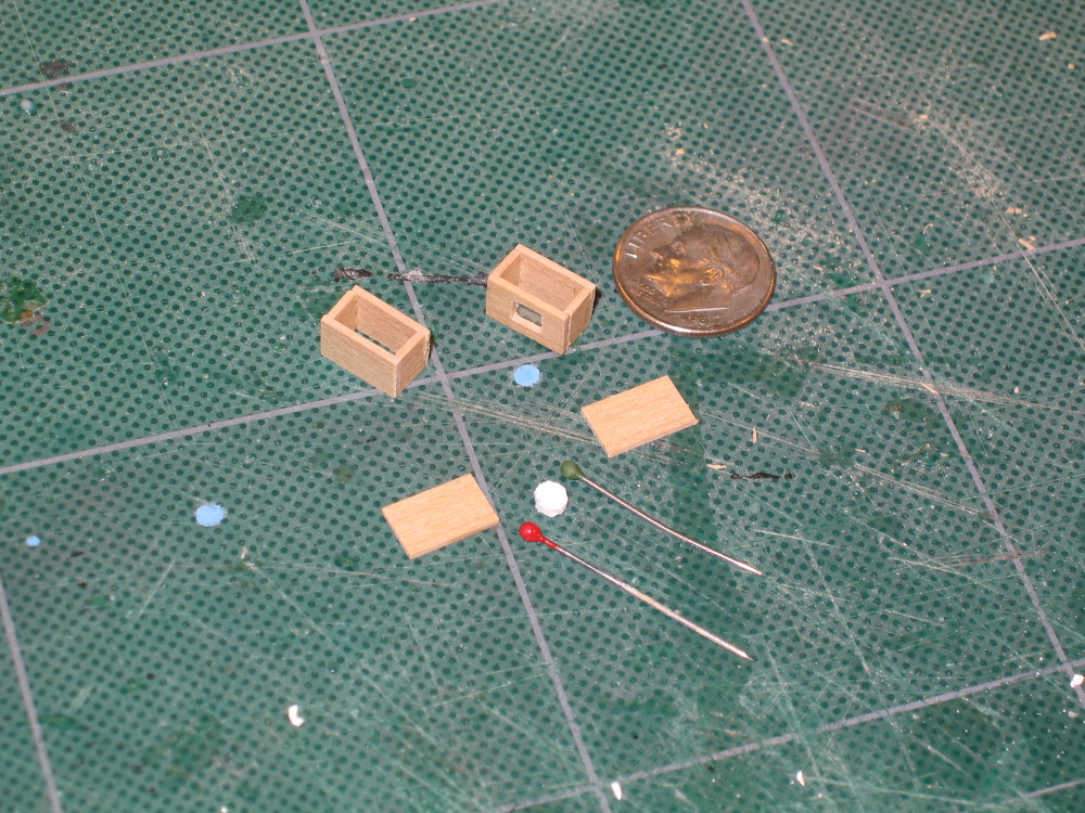
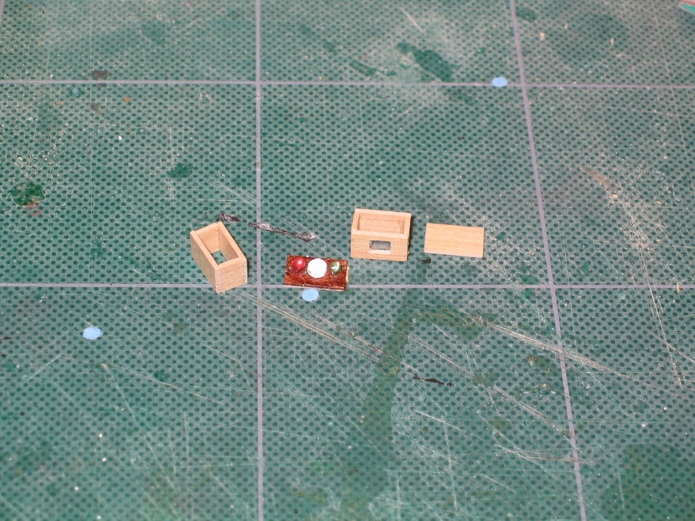
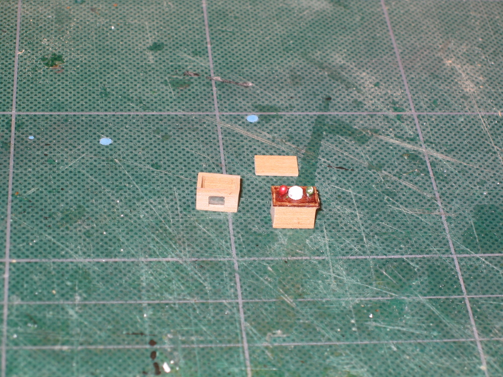
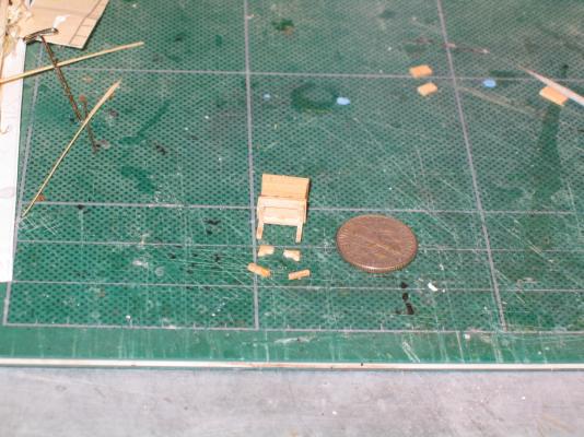
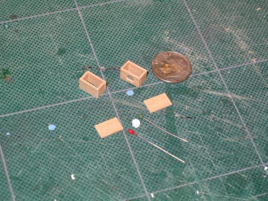
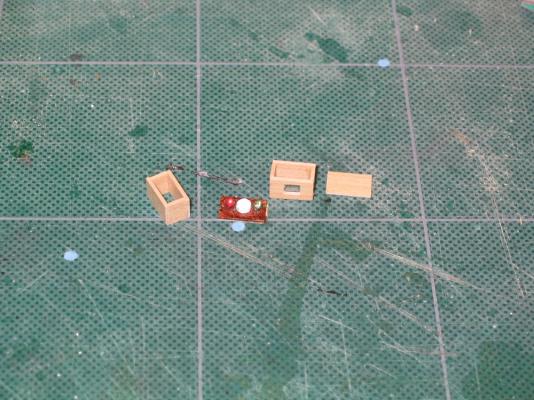
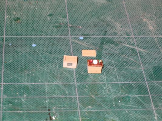
In addition to that I added the interior of the binnacle with red and green balls made from the tops of pins with balls on top and a small wooden disc to represent the metal compass adjusting balls and the compass. A piece of clear plastic completed the interior. The interior shelf top was stained and then everything was assembled.
-
The Binnacle This was another fun little mini-project. At 3/16" scale, it was very small. The upper, box portion was made from 1/32" x 1/4" boxwood. The sides are glued to each end of the front and back pieces. This is important otherwise the box will be too narrow. Glued up in this manner, the top and bottom fit creating a slight overhang on all four sides. After assembling the four sides, glue the top and bottom. Before I did this however, I cut an opening for the binnacle window in the front piece. The Practicum would have you do this after it was assembled which I don’t understand.


-
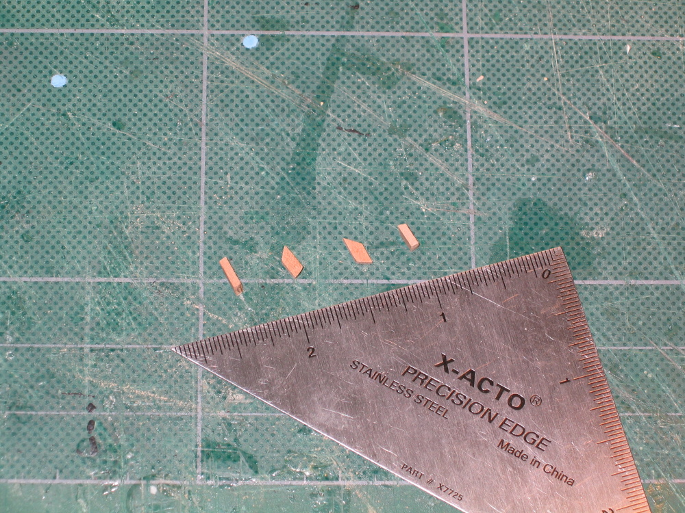
That was the easy part. The four timbers that support the taffrail were a bit trickier. The top surface of the transom is not parallel to the bottom surface of the taffrail in the fore and aft direction and the each one is at a different angle in the vertical direction. Each timber piece had to be custom made by trial and error.

-
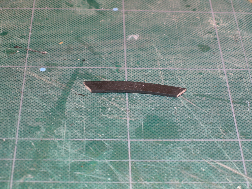
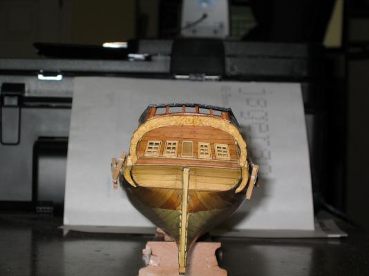
The Taffrail The taffrail is the rail across the stern transom that connects the two quarterdeck cap rails. There are four timbers beneath it that support the rail. The rail is arched across its top surface and also across its aft edge.
-
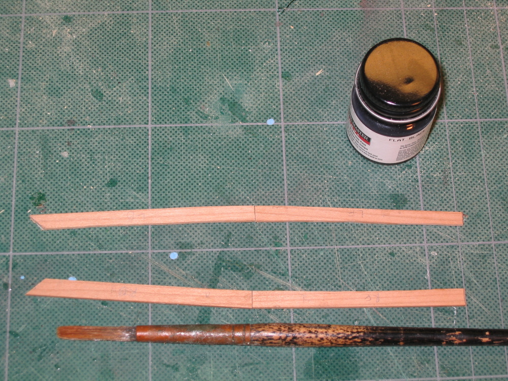
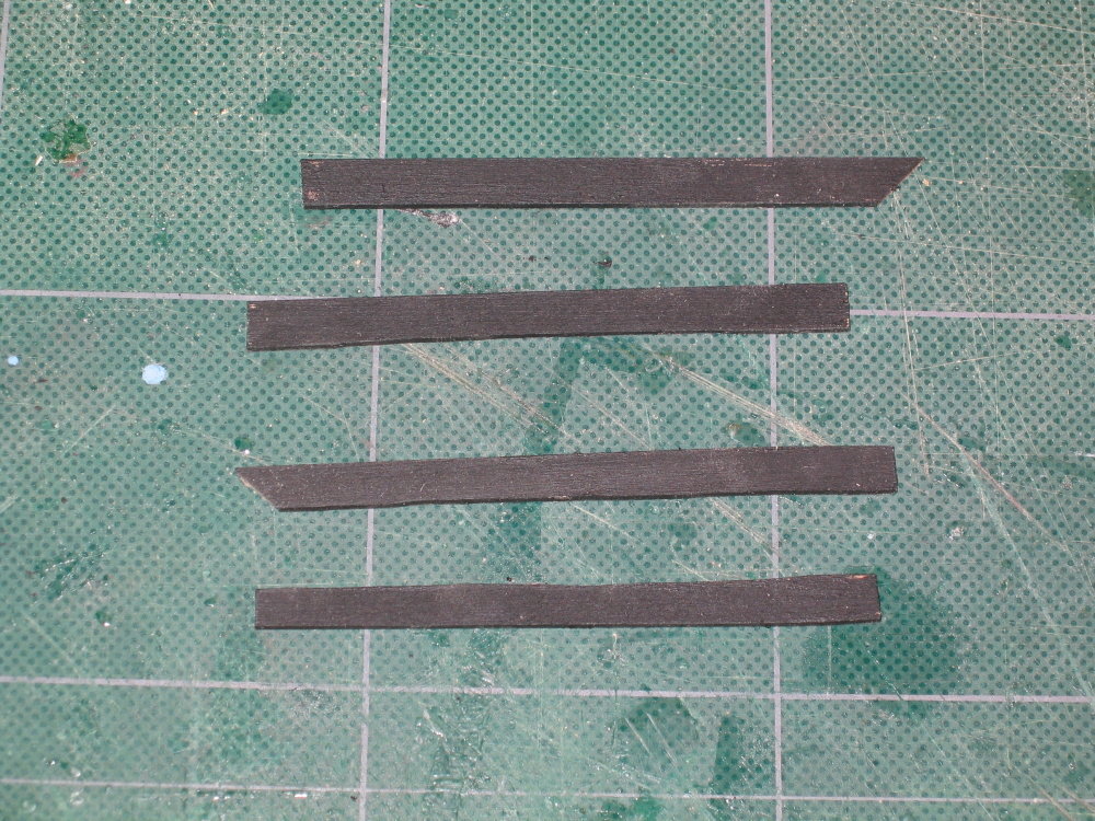
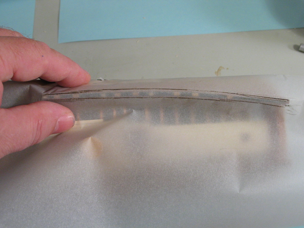
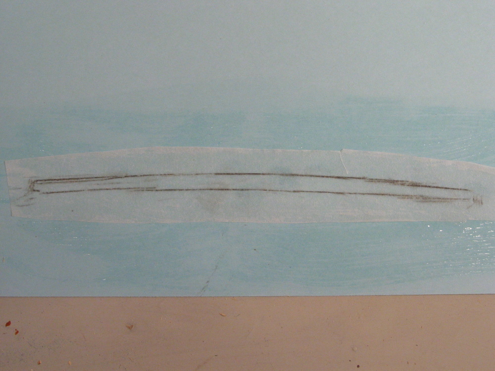
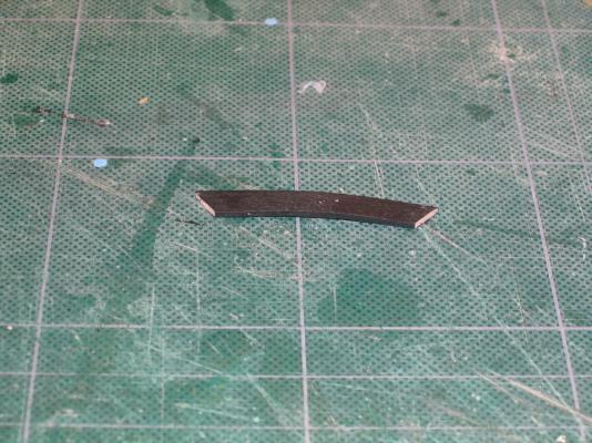
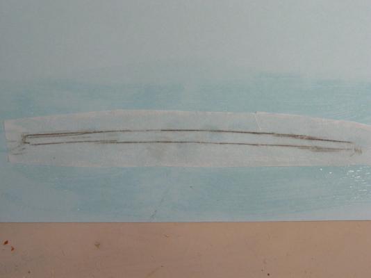
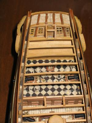
After marking the shape, the tracing paper was cut out well outside these lines and rubber cemented onto some file folder card stock with the trace markings down, not up so as to not smear. Then, the card stock was trimmed so it matched the model exactly. The card template was used to mark the shape onto the swiss pear stock. Because of the curvature of the bulwarks at the quarterdeck, it was necessary to edge glue two pieces of the 1/16" x 1/4" stock together during installation. The pattern was transferred onto the stock and cut out with the scroll saw. Once everything was dry fit, the rail caps were painted flat black and when dry, coated with ebony Minwax.

-
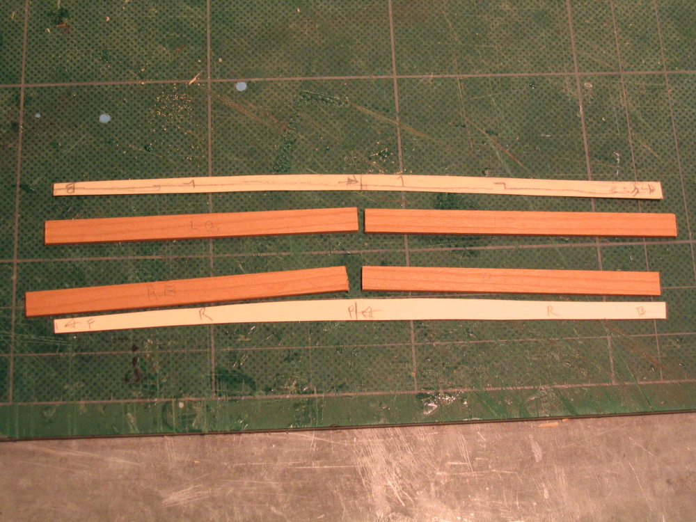
Quarterdeck Side Rails The quarterdeck rails are constructed from 1/16” x ¼” swiss pear painted/stained black. A tracing was made of the shape of the hull across the quarterdeck bulwarks, both inside and outside. This was not an exact science.

-
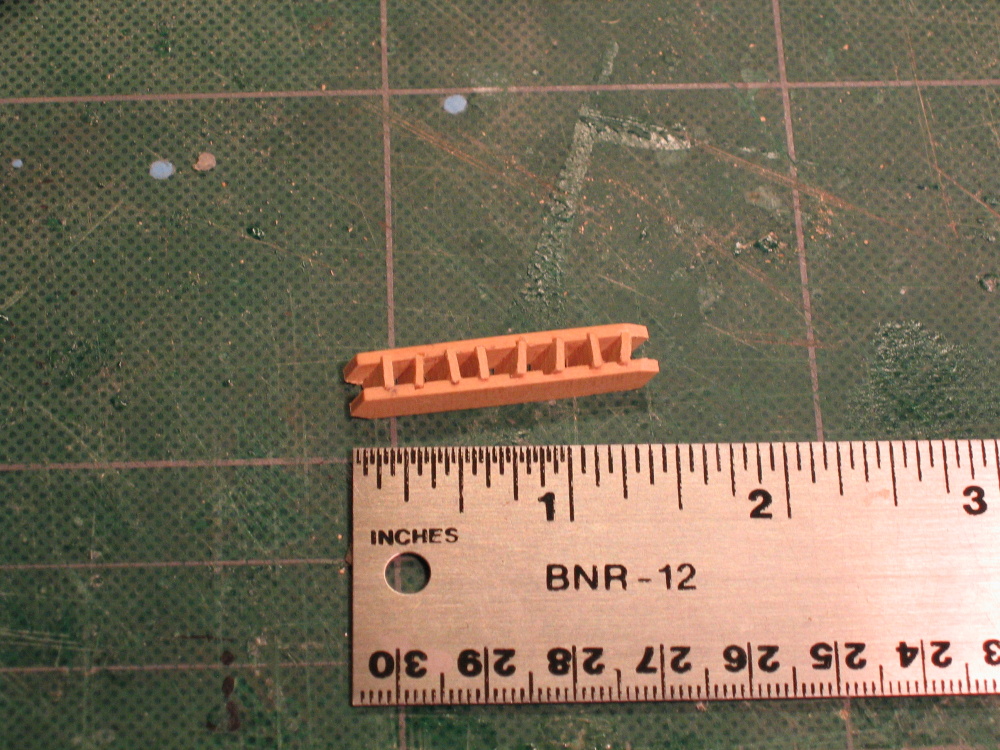
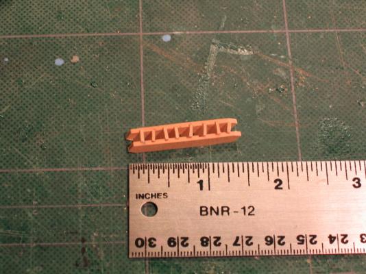
I wasn't worried too much if a step or two was slightly out of alignment because you would never really see it. Somehow the scale of the wood thickness seems off. It looks like it could have been half the thickness but maybe that would have made the ladder too delicate.

- 974 replies
-
- 1
-
-
- rattlesnake
- mamoli
- (and 1 more)
-
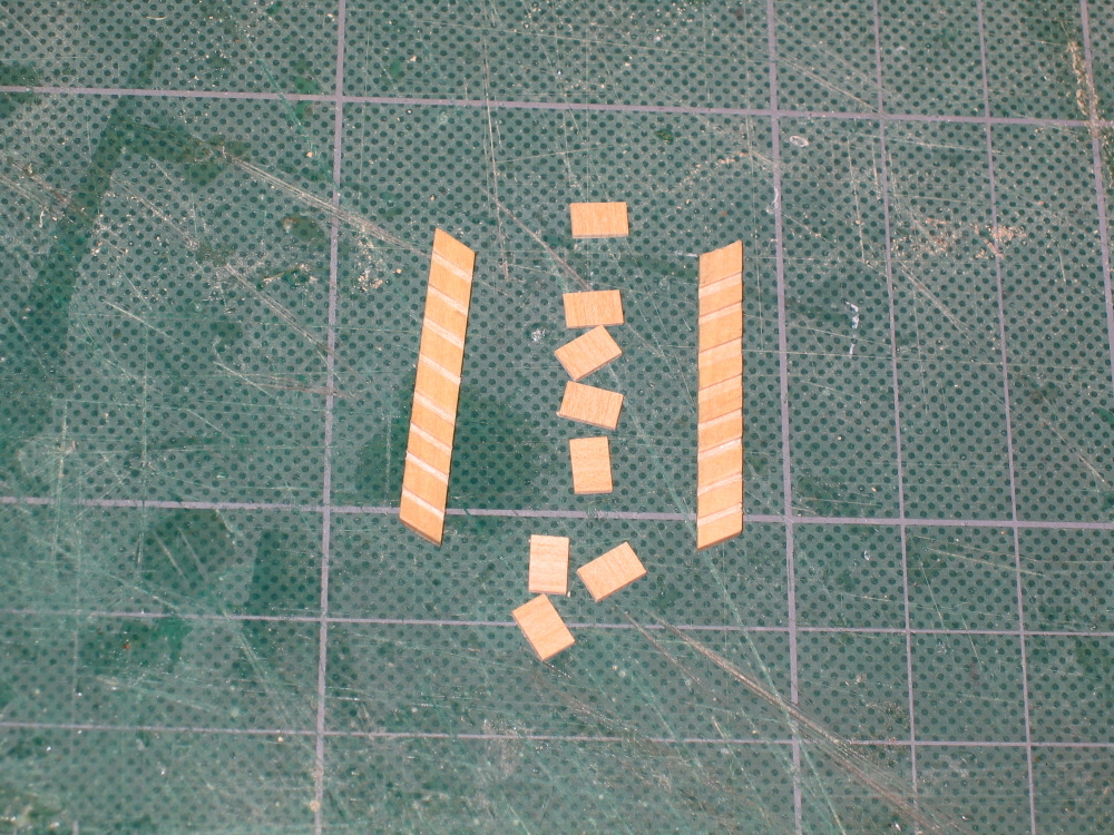
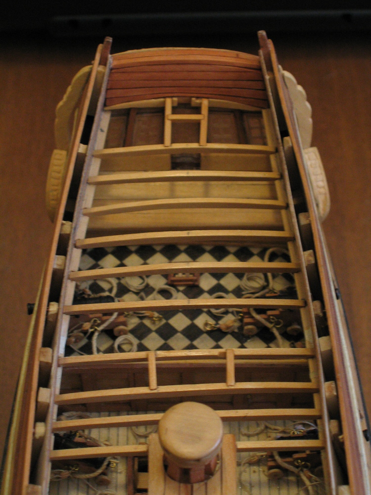
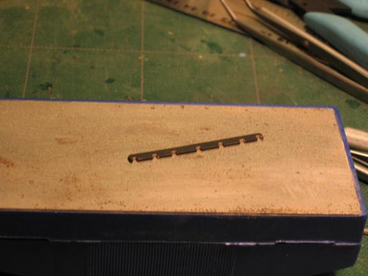
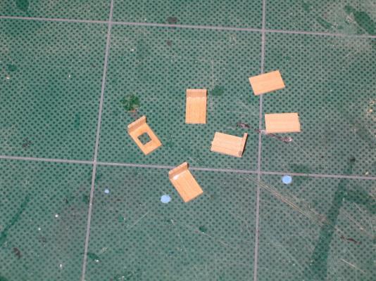
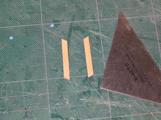
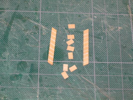
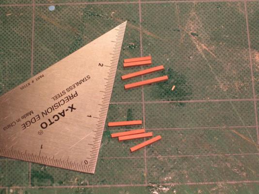
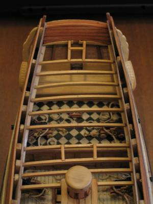
Aft Hatch Ladder The ladder is made of 1/16" x 3/16" boxwood with eight 1/32" x 1/4" steps. In retrospect I should have made the steps steeper and probably ended up with seven steps. The Practicum stated that there were “approximately six steps” depending on the model.
-
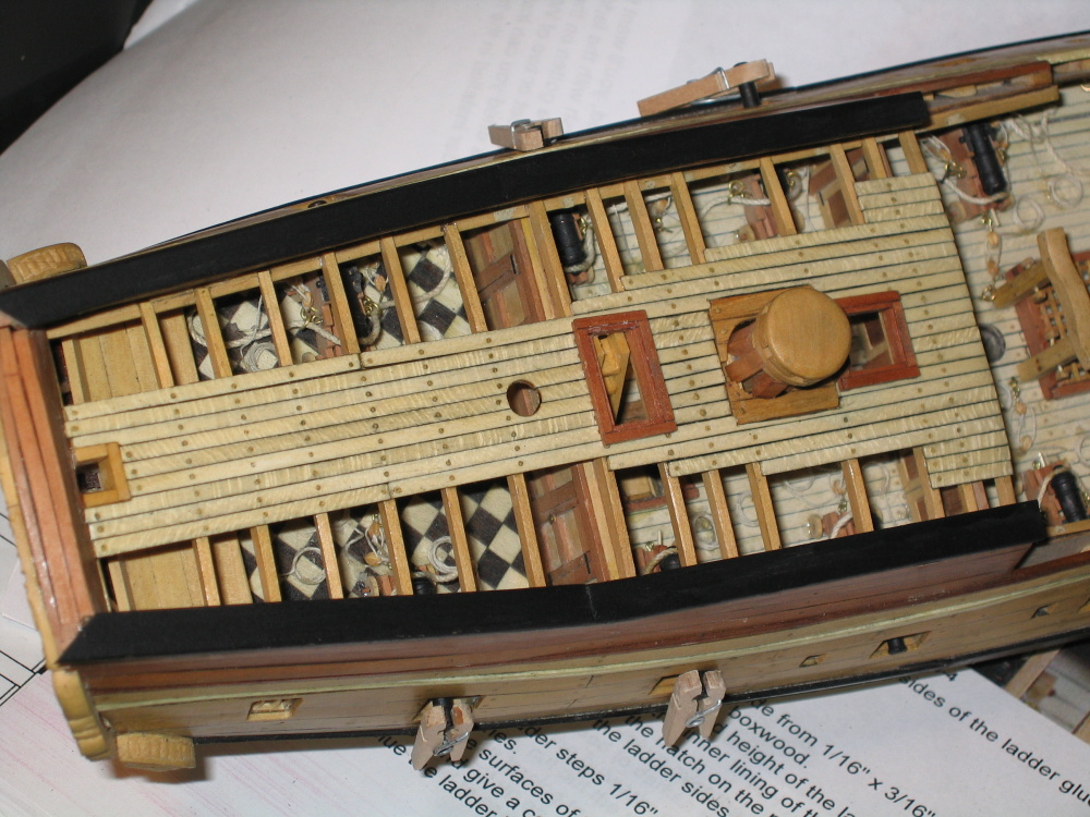
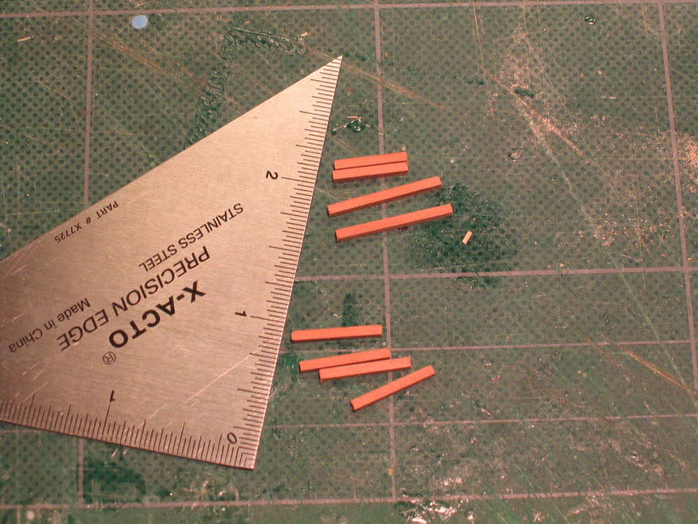
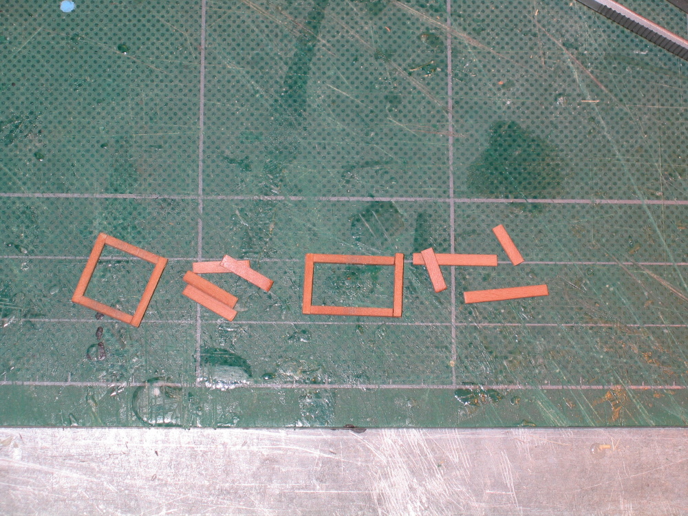
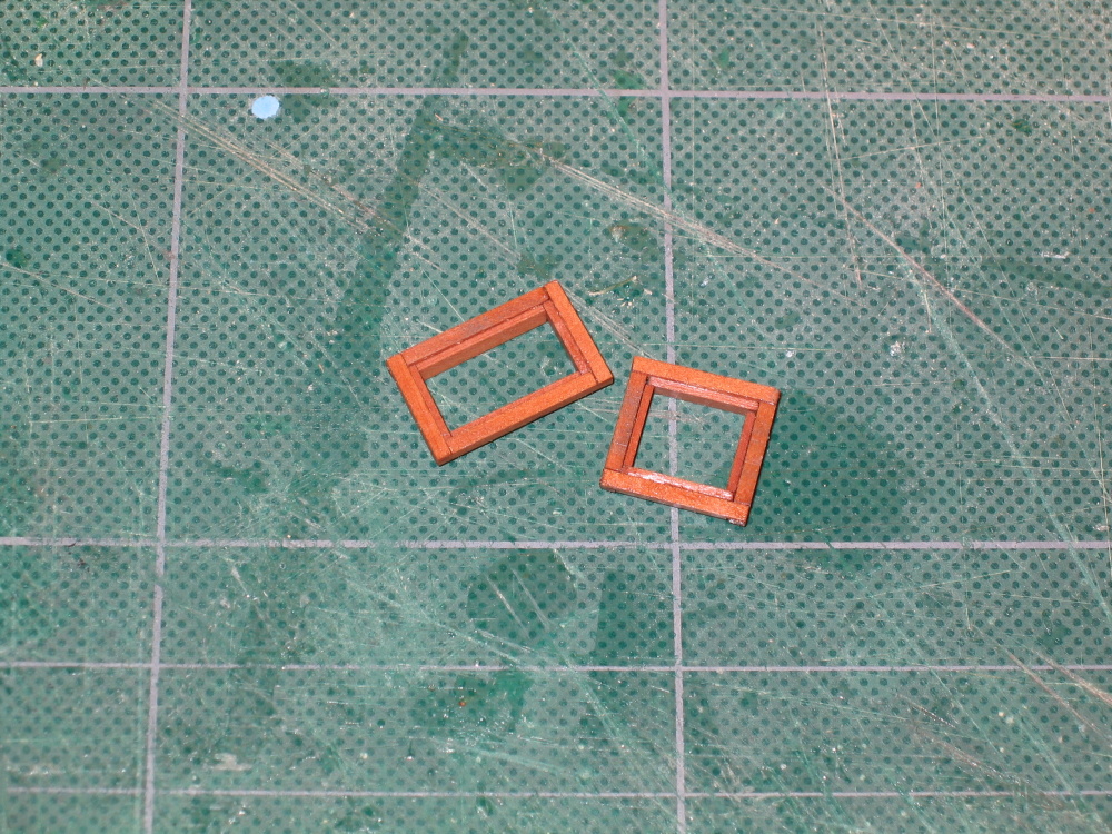
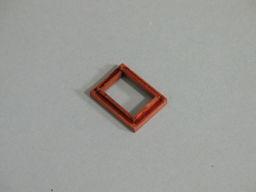
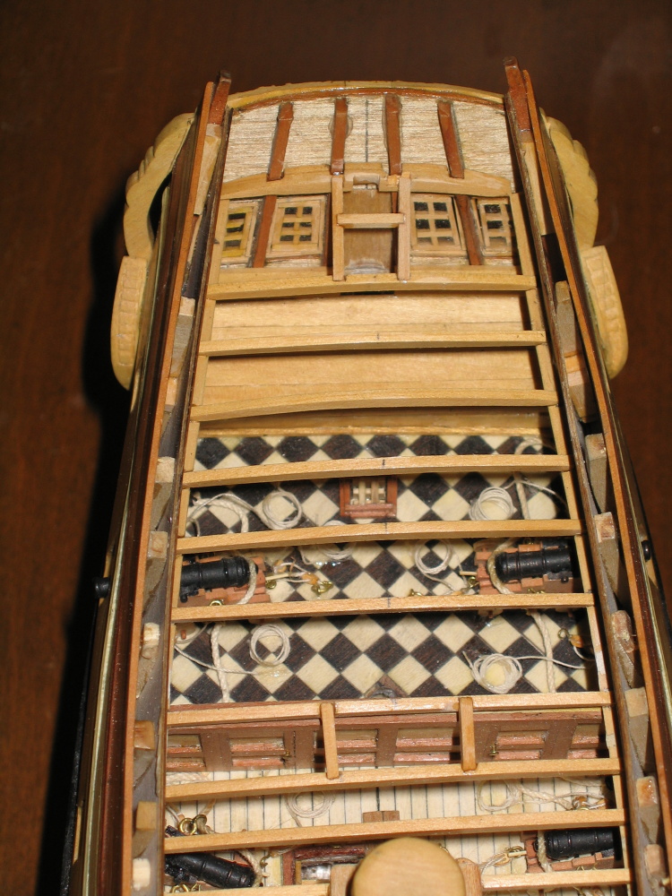
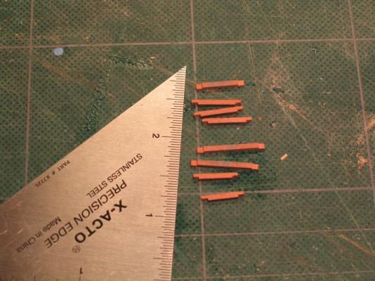
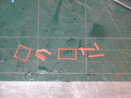
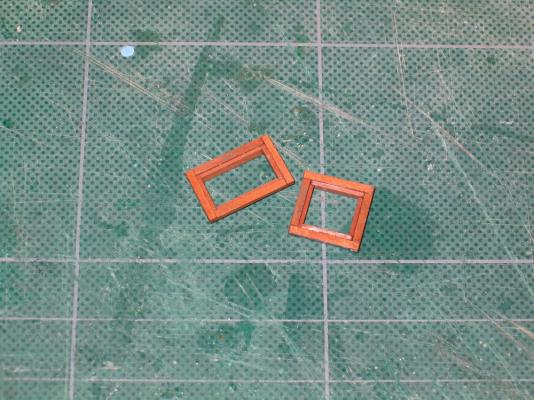
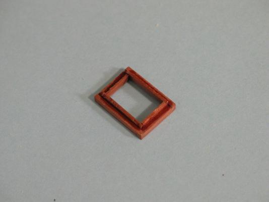
Quarterdeck Hatches There are two hatch openings on the quarterdeck which were framed and planked around earlier. The hatches for those opening are made using swiss pear. The aft opening was made from 1/16" x 1/16" swiss pear and was constructed just like hatches on the main deck, the corners were lap jointed. The interior of the openings has a lip that a grating would sit on if it were installed. I’ve include an image from the Practicum which shows the lip from the underside.
- 974 replies
-
- 1
-
-
- rattlesnake
- mamoli
- (and 1 more)
-
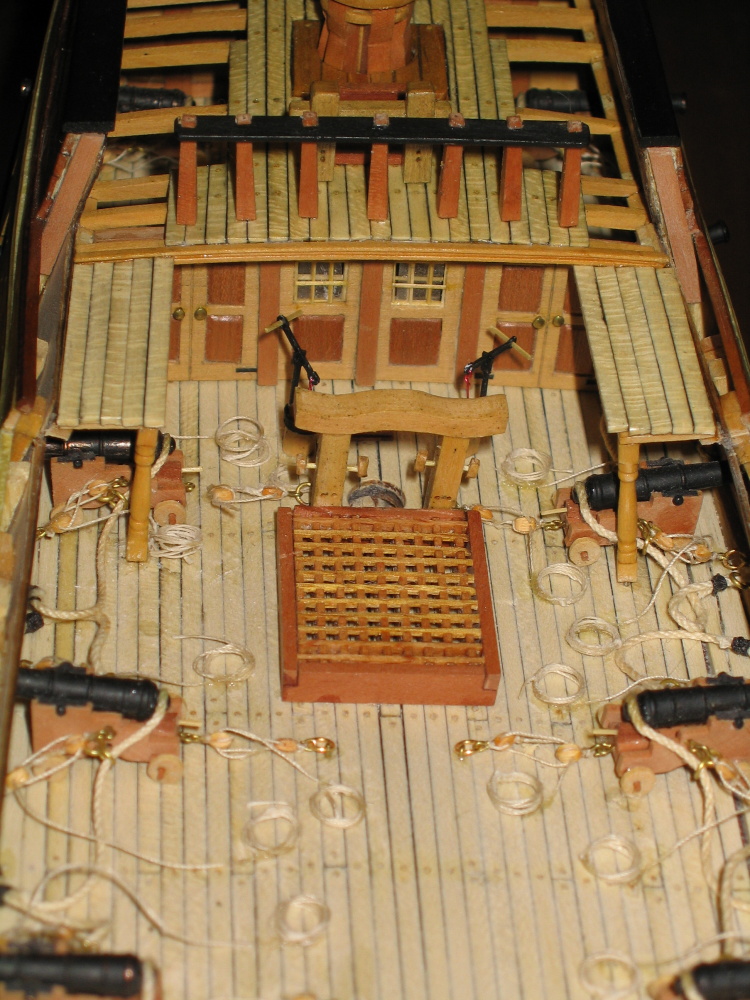
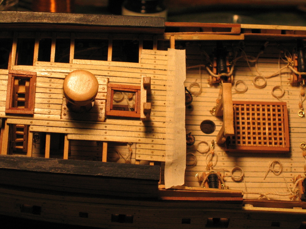
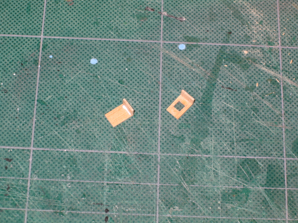
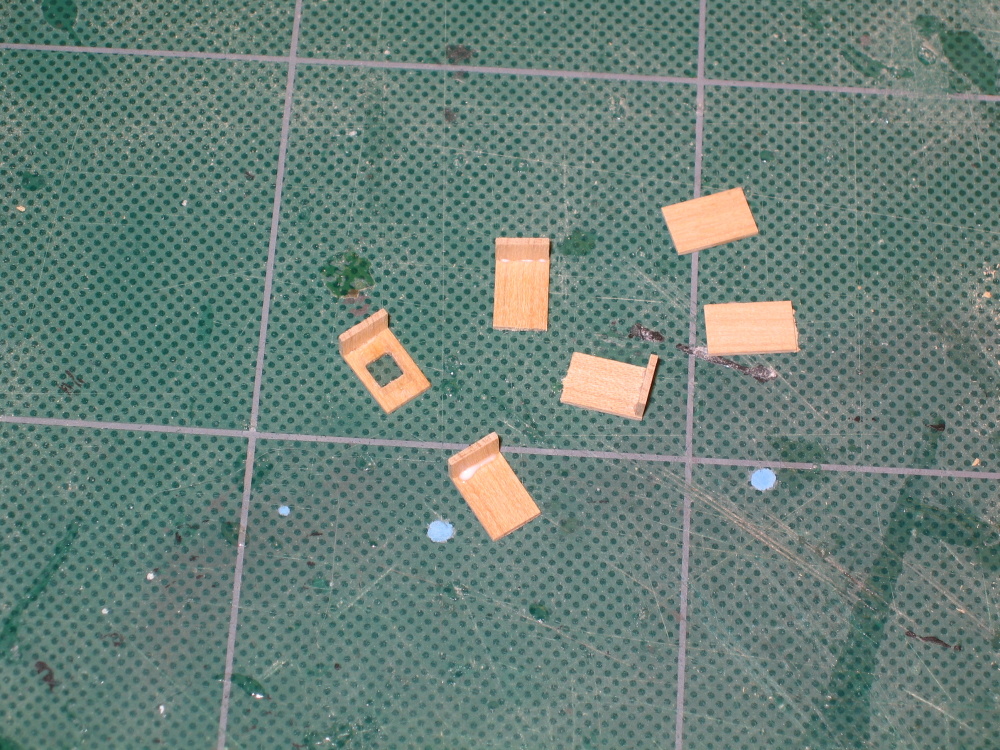
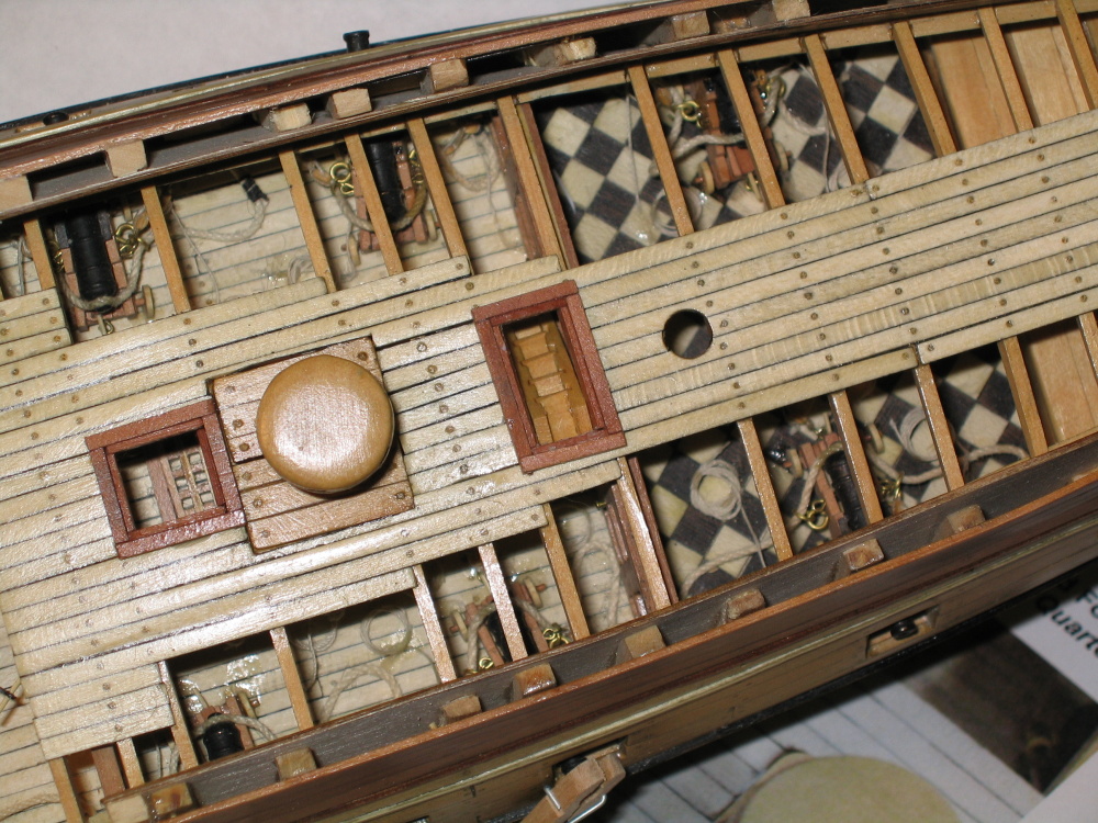
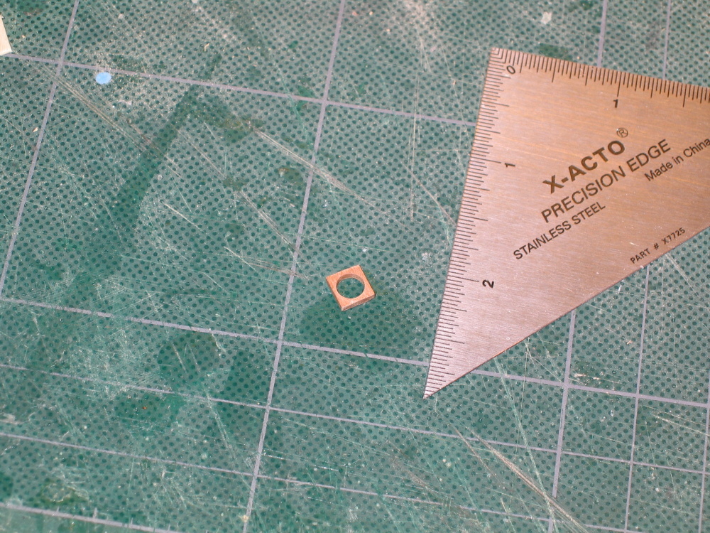
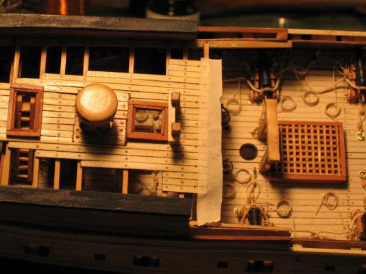
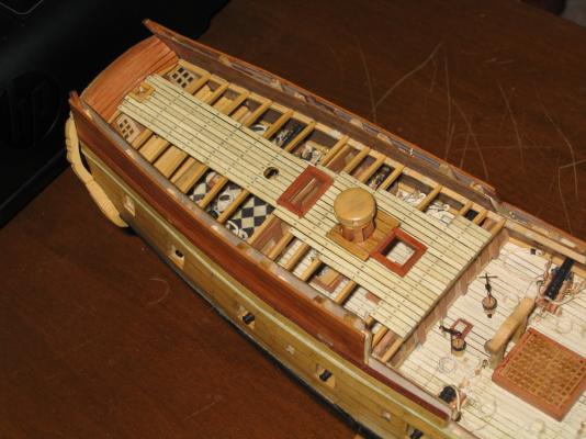
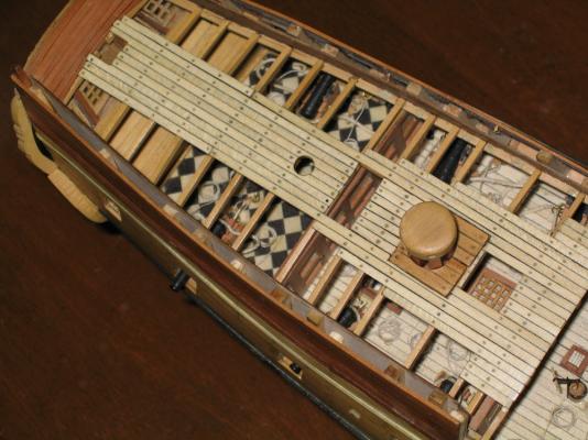
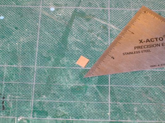
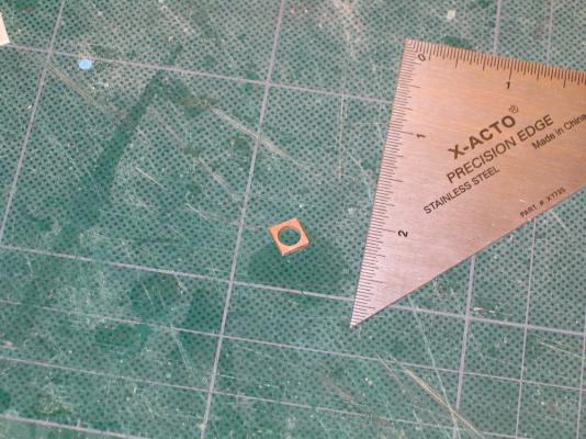
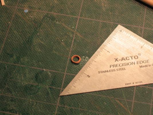
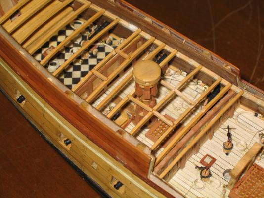
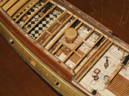
To install the mast wedge is a little tricky. After inserting the mast through the Quarterdeck, the wedge is inserted onto the mast. The mast is then lowered and inserted into the mast hole in the parquet floor. Using a pair of tweezers the wedge is held in place while the mast is removed. I used Weldbond glue because I didn’t want the wedge to adhere to the mast and I wanted some wiggle room when it was being glued to the deck. In the picture below, you can see the wedge in the center of the image.

-
Main Deck Mizzen Mast Wedge At this point, the Practicum directs the builder to fashion a mast wedge to be placed on the Main Deck for the Mizzen Mast. The Practicum explains why it was not installed earlier. The mast has a rake aft and the mast wedge must fit tightly around the mast. Also, you could run into an alignment problem as Mr. Hunt did when he fit the mast if the deck beam this hole is up against is too far forward. Using a piece of 1/16” swiss pear ¼” square, a hole is drilled and widened to 3/16”. Then another ring is drawn 1/16” from the hole’s edge. The excess is trimmed off and the upper edges are rounded over. The aft bottom edge is filed a bit to accommodate the rake of the mast.
-
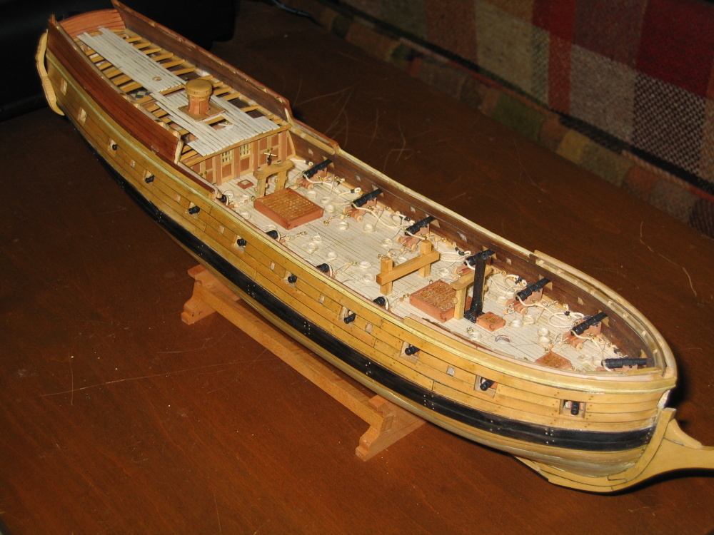
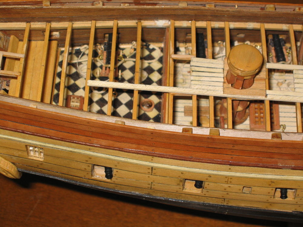
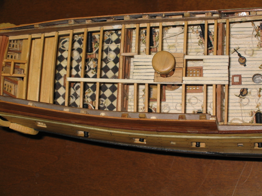
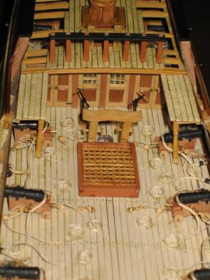
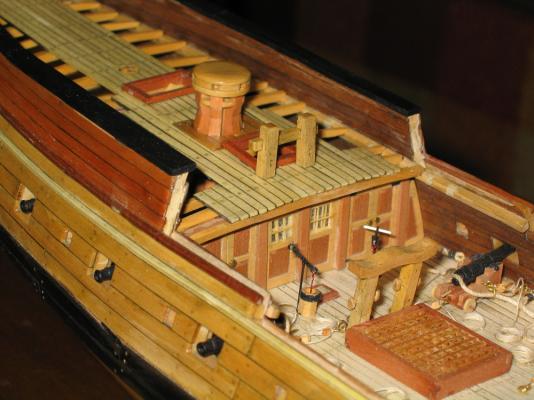
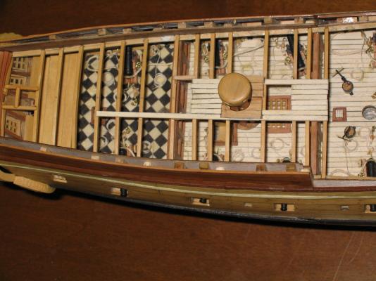
Initial Quarterdeck Planking If the Quarterdeck were to be fully planked, there would have been no reason to do a lot of the previous work because no one would have been able to see it. Therefore the Quarter and Fore Decks are partial planked. The planking starts in the center and works its way out as well as fore to stern. The planking is the same as the lower deck with charcoal to simulate caulking and bamboo for tree nails.
- 974 replies
-
- 1
-
-
- rattlesnake
- mamoli
- (and 1 more)
-
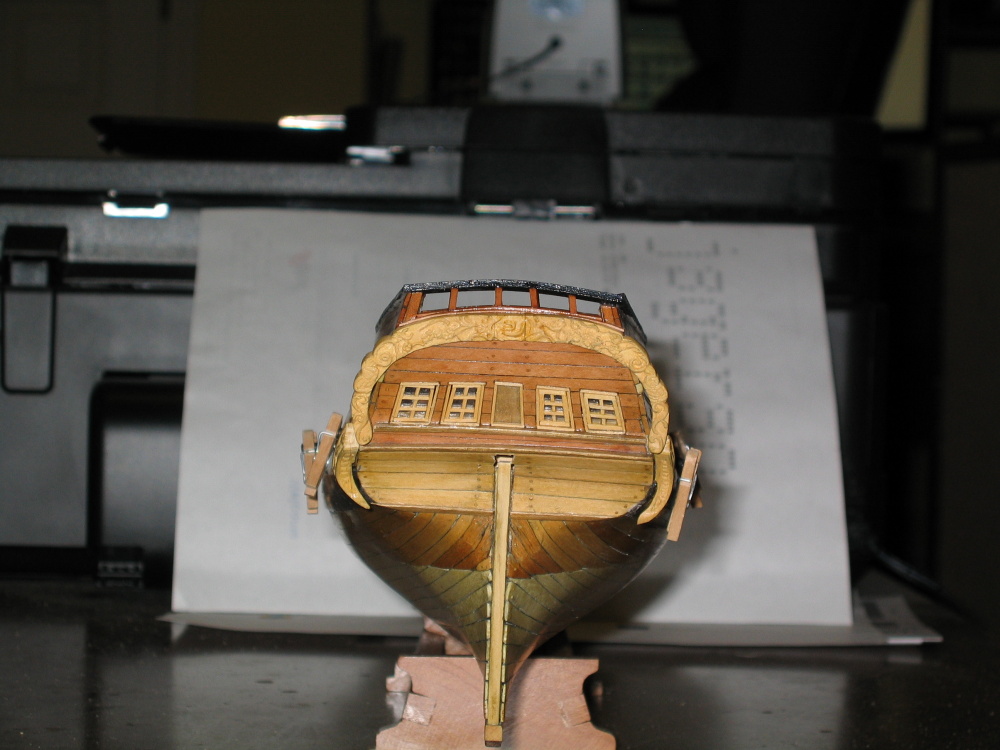
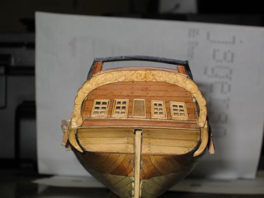
After the frame work for the tiller post was done, the interior of the transom was planked with swiss pear. If you remember in Chapter 1 I discussed the transom cap that the Practicum initially instructed the builder to put on, but I found that it got in the way. When it got knocked off, I left it off. Here at this stage is where it needs to be installed. However, instead of using the 7/16” x 1/32” swiss pear, I elected to use the swiss pear planking. It just looked more realistic to me.
-
The Transom and Rudder Tiller Lining The area of the transom required compromises as well. See all these little mistakes a novice like myself made comes back to haunt you and make what is complicated, more difficult. The good news is that hopefully I have learned from my mistakes. For some reason, the stern on my model does not quite match up with the plans. This was mentioned back in Chapter 1. Now it was time to pay the Piper. The rudder tiller lining opening is not where it is supposed to be, but further back against the transom. I had to frame the opening as best I could. The lining ends up flush with the deck planking as it was supposed to. These pictures were taken before I realized that the right side of the opening was a bit off. This was corrected but I did not take another photo.
-
Because I didn’t think that back in the late 1700’s they would have used a slab of wood that large, I scribed the pieces with an X-acto blade and a pencil to make it look like planking. The each piece had a large half circle cut out of it the same diameter as the capstan with whelps instead of the capstan post. The two pieces then were wrapped around the capstan and glued into place.
- 974 replies
-
- 1
-
-
- rattlesnake
- mamoli
- (and 1 more)