Check out our new MSW Sponsor Innocraftsman
×


JSGerson
-
Posts
2,603 -
Joined
-
Last visited
Content Type
Profiles
Forums
Gallery
Events
Everything posted by JSGerson
-
 It took a bit of searching but I found the reference to the dremel method of treenails. He also pointed to a forum which somehow I missed devoted to making treenails. My method which I learned by trial and error is really simple, relatively fast, and easy, but the fingers do get sore if you stay at it too long. I chose garden variety grocery store bamboo skewers as my base stock material because Mr. Hunt used bamboo. He however had some fancier stock material and used a Dremel treenail cutter of some sort. I really don't know. I then split the skewers into four or five splinters. Each one had pointed ends, well because they started as skewers. As I mentioned earlier in the build log I started off with a draw plate I bought from Model Expo but was dissatisfied with it. Then I discovered Jim Bryne's draw plate and what a difference that made. Each skewer splinter would generate 30 - 40 treenails after you cut the nails to length. It took me only about 10 minutes or so to turn one splinter into treenails. To install the treenails, I first used a common pin to located and create a starter impression for the drill in the wood. Then I used a push type hand drill as opposed the twist type to create the holes. You can really drill a lot of holes without you hand getting tired. Then I used a needle nose pliers designed to handle model railroad spikes. It has a groove cut into to securely grab the spike or in my case the treenail. That made insertion real easy. If someday I need to make treenails for a larger scale model, I probably will try the one toothpick equals one treenail method because I'm guessing pulling thicker wood through a draw plate will just be too hard. All that said, I'm glad that for this model I'm done with treenails...I think! Jon
 -
I'll tell you, I'm glad that's over with. Pulling those bamboo strips through the draw plate hurts your fingers after a while. If I used a tool like pliers to grip the bamboo, it destroys the ends because the pieces are so thin. Well the next item appears to be bow railing - this should be fun.
-
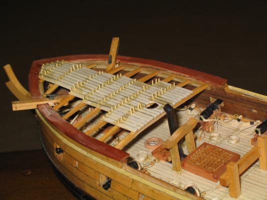
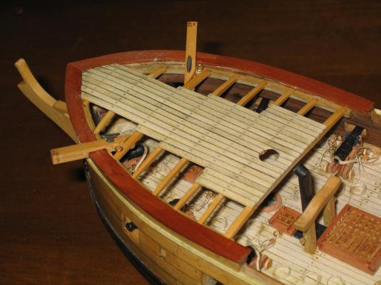
Forecastle Deck Planking – Final One last time (I think) I broke out the draw plate and drew the bamboo strips (formerly bamboo food skewers) through the holes till they got through the #29 orifice. Cutting the fine dowels into short pieces resulted in treenails that fitted the hole the #69 drill made very nicely. The holes were drilled like before on the quarterdeck where the planking crossed the deck beams and the tree nails inserted. Using the Poly-wipe as my adhesive, a tiny drop was applied with a toothpick at each hole. There was no worry if I got sloppy as the whole deck would eventually be coated with it. Once I felt the treenails had been secured after a couple of hours of drying, the excess bamboo was snipped off and sanded down flush. The whole deck was then sanded. The deck was applied with poly-wipe, sanded, and applied again.
- 974 replies
-
- 1
-

-
- rattlesnake
- mamoli
- (and 1 more)
-
You had the same wood problems? I purchased my package in Nov 08 probably before you although you are ahead of me in the build. From the correspondence I had wilh Jeff, the deficiencies I found a few years later were news to him. I basically have one chapter to go to finish the hull so hopefully I won't have any more wood problems. It appears that those problems were not the result of anything Jeff did or did not do. He inherited the list of wood type and sizes from the previous suppliers. Jeff informed me that somehow nobody told him (or the previous suppliers) of the inaccuracies or errors in the list until I did. I sure that any future buyers of supplemental wood for the Rattlesnake will not run into the same problem I had now that Jeff has been informed. You mentioned that you substituted boxwood for the dowels used for the masts and yards. Why? Was it a good choice? If I choose to go that route, would you be willing to give me that substitute wood list?
-
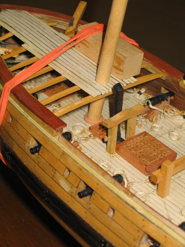
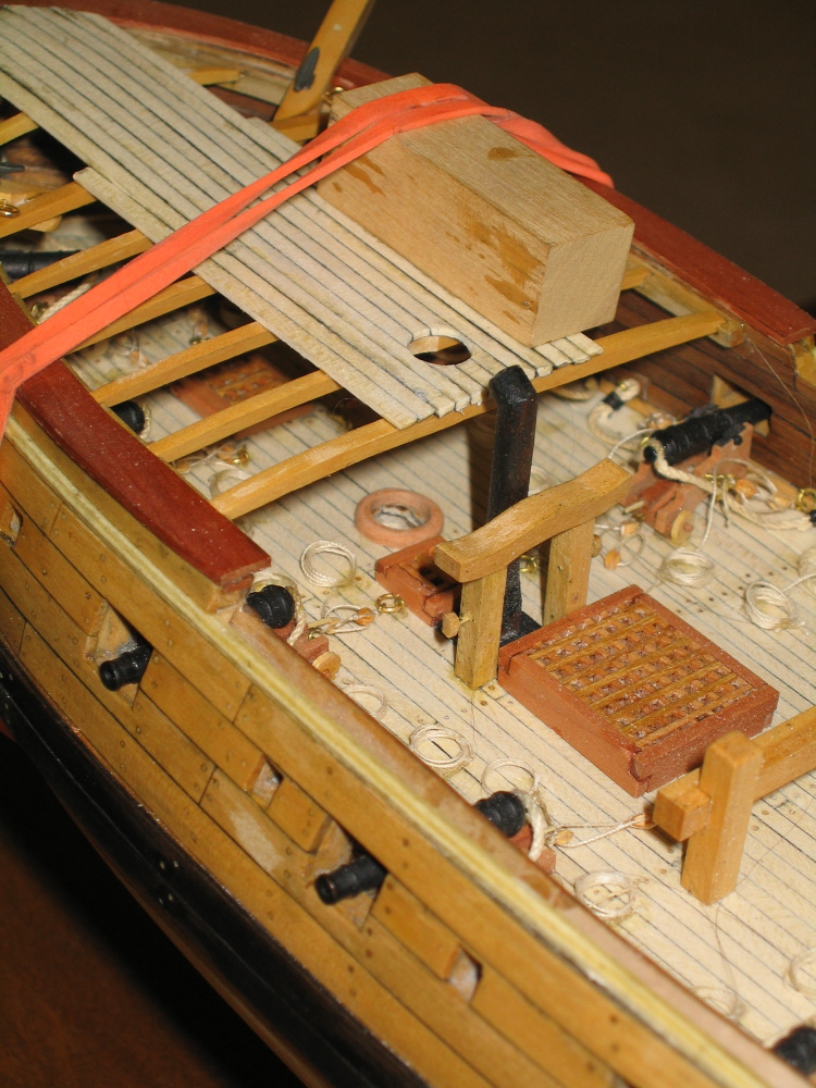
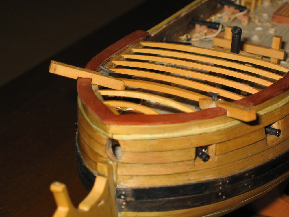
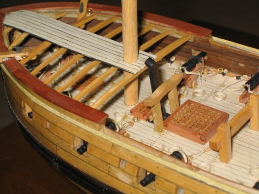
The wedge was installed under the foredeck by placing it on the dowel after it had passed through the foredeck. The dowel was then positioned and inserted into the main deck mast hole and the wedge was then pressed to the deck. Once the Weld Bond glue had taken hold (about three minutes), the dowel was removed. The remaining wedges were set aside for later. The planking continued.


-
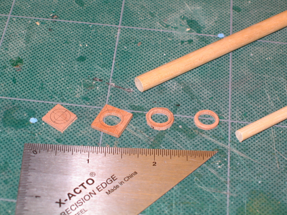
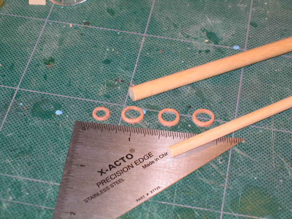
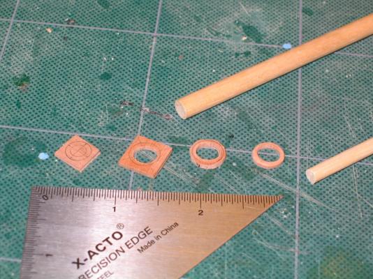
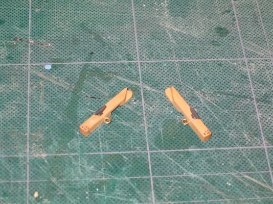
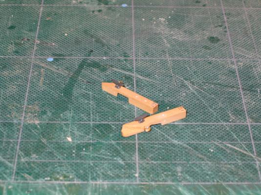
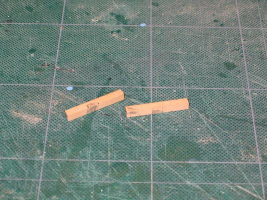
Mast Wedges At this point it was time to construct the main deck mast wedge under the foredeck like was done for the main deck under the quarterdeck. But an unforeseen complication arose; per the instructions of the practicum. In Chapter, 8, section 8.1.3, Page 24, Mr. Hunt describes the creation of the mizzen mast wedge for the parquet floor on the Main deck. The stock material was 1/16" x 1/4" swiss pear which was based on the 3/16" dia of the mast:+ 1/16" + 1/16" (thickness of ring on either side of mast) = ~1/4". The wood package contained 1/16" x 1/4" swiss pear. So far so good. In section 8.2.4, Page 108, the practicum addressed the foremast wedge under the forecastle. It stated: "And like the mizzen mast, there is a small mast wedge made of swiss pear on the main deck...The mast wedge was made the same way I described earlier." The foremast is 1/4" in diameter. To make the wedge I would need a stock piece of 1/16" swiss pear of at least 3/8" square: 1/4" + 1/16" + 1/16" = 3/8". There are a total of 3 wedges of this size, two on the main deck and one the forecastle. The wood package had nothing in swiss pear of this width in any thickness. At this point my only alternative was to create them in boxwood and then stain them as best I could. I immediately contacted Jeff Hayes of HobbyMills and started the email with “You wouldn't of seen this one coming.” Mr. Hayes was again very gracious: “I guess that Bob just used some pear that he had lying around and forgot to add it to his list. If you need a piece of 1/16 sheet stock, just let me know. As an alternative, how about gluing two layers of the 3/64 x 5/8 together to make them?” Looking at my supply of 3/64 x 5/8” swiss pear, I realized that that didn’t have too much left and didn’t know if I would need it later so I reluctantly went with his first option. Letting Jeff know I felt guilty about “nickel and dimeing” him he asked and I agreed immediately to at least pay for the postage. Within a couple of days I received a piece 1/16” swiss pear 1 1/8” x 24”, more than sufficient to create the wedges and anything else I might need. Thanks Jeff. Well if I was going to make one wedge, I might as well make all of the remaining wedges. Here you can see the progression in mast wedge construction.

- 974 replies
-
- 1
-
-
- rattlesnake
- mamoli
- (and 1 more)
-
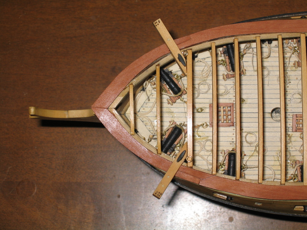
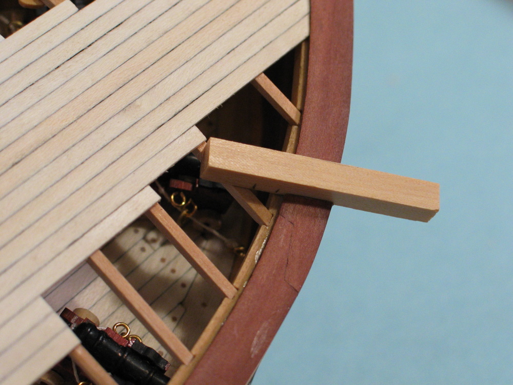
To ensure proper fit, dry fitting with the dowel was done numerous times.
- 974 replies
-
- 1
-
-
- rattlesnake
- mamoli
- (and 1 more)
-
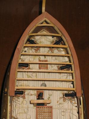
Forecastle Deck Planking – initial With the catheads installed, it was time to start the forecastle deck planking. Just like the quarterdeck, 1/32” x 3/32” holly was used. Starting from the center the first plank was set in place. The practicum would have me lay out all the planks and later on drill out the foremast hole. I elected to create the foremast hole earlier. As soon as I had glued down the second plank, a notch mas make in the center plank to indicate where the foremast was to pass through the deck. By the time I had five planks down, I commenced to complete the hole. I wanted the five planks glued in solid so that when the hole was expanded to fit the dowel that would become the mast, there would be enough strength to resist drilling and filing. The mast has a rake to it and the deck hole butts right up to the support beam below so everything had to line up perfectly.
- 974 replies
-
- 1
-
-
- rattlesnake
- mamoli
- (and 1 more)
-
Thanks. I'm not ready to start rigging yet so I'll wait for a sale that applies to the plans. $50 is $50!
-
"I received the ModelShipways Rattlesnake plans as an additional reference (gee, why am I putting in all this extra time and $$ on this.............I might be rigging by now...)" I am contemplating getting a set of the ModelShipway Rattlesnake plans myself. I have not seen what the plans look like. Is there anything in them that it is worth the $50?
-
I am waiting with anticipation to see how you install these fixed blocks onto your model. As you may know I'm following Mr. Hunt's practicum and his method for installing these is totally different but I didn't really like his results. Of course I'm no expert either in historical ships or model making and I would have followed his method blindly, but so far I like your method. I can't wait to see what you do next.
-
Very neat job. For hinges I just used black paper and for the door knobs, the head of some finishing brads I had from an old kit of some sort.
-
Yeah, they now have a coat of poly-wipe on them where as before they didn't. Right after I plank the quarterdeck, I get to go the rail process one more time when I put in the hand rails. That should be as much fun fun!!
-
I went a step further than the practicum and added the cleats and rings. It seemed a whole lot easier to do that now before installation on the model than latter when Mr. Hunt did his.
-
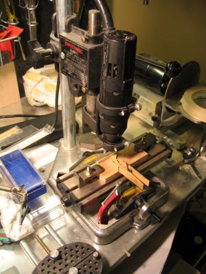
Based on those marks, the areas to be cut out were blackened so as to make it clear where to cut. Using the fine tooth hand saw from my miter box and micro chisels, the appropriate areas were removed and fitted. This took me two attempts with the second being adequate, not perfect. At the tip of the cathead are six holes for rigging the anchors. The kit shows only four. Knowing that I had to drill through 5/32” six times precisely I used my Dremel drill press jig. Now I am blind as a bat and have to work with an eye loupe attached to my tri-focal glasses. Trying to get my head close enough to the drill press work area so that my lenses would focus, was a challenge. I would have sworn I was right on my marks but the results left something to be desired. If I had a true drill press, I don’t think I would have had the same results. The drill drifted because the jig wasn't as rigid enough so that the holes are not exact where they should be. The imperfections are there if you look for them.
-
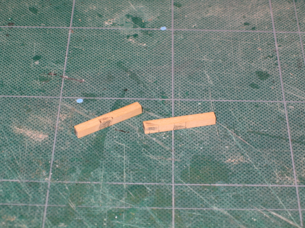
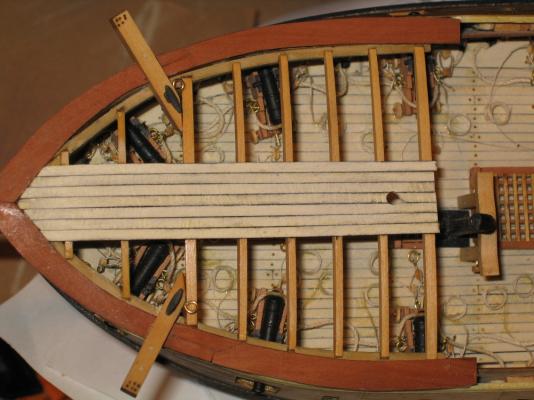
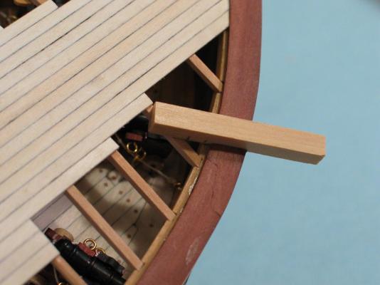
The Davit Catheads This turned out to be a race in patience. Would I run out of patience before the pieces were completed? It was almost like weaving wooden sticks. The catheads start under the forecastle beams and end above and resting on the bow rail with few perpendicular cuts. Starting off with a piece of 5/32” square boxwood stock, two pieces are cut 1¼” in length. Laying each one on the appropriate bow rail and the third beam back from the tip of the bow, marks were made to indicate were these piece would cross either over or under structural points. The third beam by the way is wider than the other beams. This is illustrated in the practicum. You will notice that Mr. Hunt has already planked the forecastle.
-
Just a couple of quick questions, who makes serving machines and where did you get yours?
-
Thanks for the undeserved compliment. Until you mentioned it, I wasn't really aware of the boomkins. As a matter of fact I had to look up the term to see what you were talking about. And you are right. Bob Hunt does not address them, yet there they are in the Mamolti and Han's plans. I have on my computer 42 folders of rattlesnake models made by different people. Some of those folders have just the final model with a few images and to others with the complete build. I checked every image that showed enough detail in the bow to see how the boomkins were constructed. Surprisingly not all the models had them and those that did, I couldn't see well enough to see how it was done. The plans don't show enough detail either. I don't know what the MS plans show because I don't have them...yet. I'm waiting for a Model Expo sale that will cut down the $50 price tag. I'll have to do some more research in the few books that I have. From what I can see, it looks like I have some time yet because it appears that they should be constructed somewhere in Chapter 9 of the practicum had they been addressed. I haven't finished Chapter 8. Thanks for the heads up.
-
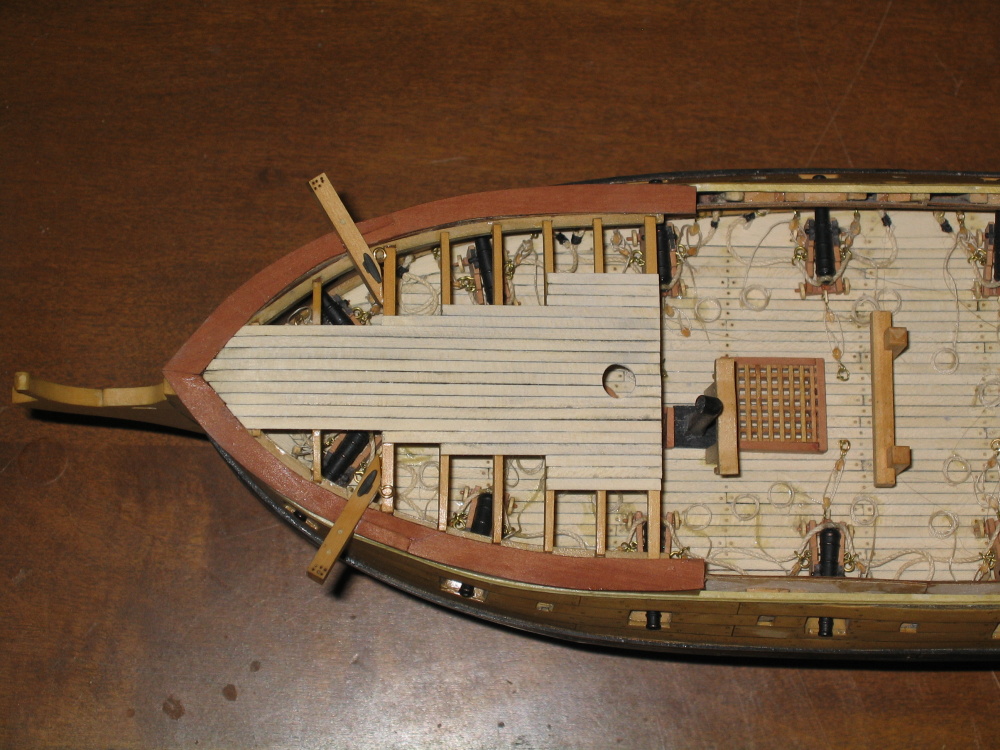
Practicum Deviations At this point the Practicum would have me plank the quarterdeck. This won’t happen yet. I've opted to skip this step and build the two davits first while the deck beams are still exposed. Then I’ll go back and plank the deck. I was surprised that the Practicum did not address the bowsprit at this point. Once the quarterdeck is planked, you cannot see the deck below where the bowsprit is attached. If any adjustments have to be made during the construction of the bowsprit to make sure it mates properly with the ship’s deck, this would be your last opportunity to do so. The Practicum does not address the bowsprit until Chapter 1 of the Rigging Supplement which follows the final hull construction Chapter 9. I went ahead and constructed the basic bowsprit mast without any of its accouterments to make sure it at least fit properly. For sake of continuity this will be discussed when I actually start assembling the bowsprit.
-
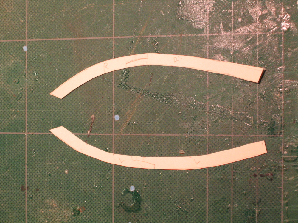
The pieces were then cutout using my old Dremel scroll saw and finally glued into place. This was not as easy as it appeared. I had a devil of a time getting all the pieces to fit right. I even had to make two of template pieces over again. I got it to work and accepted it, but still not really truly satisfied. If you look closely, where the left scarf joint broke during the cutting process. I got it mended OK, but couldn’t remove all of the glue stains.
- 974 replies
-
- 1
-
-
- rattlesnake
- mamoli
- (and 1 more)
-
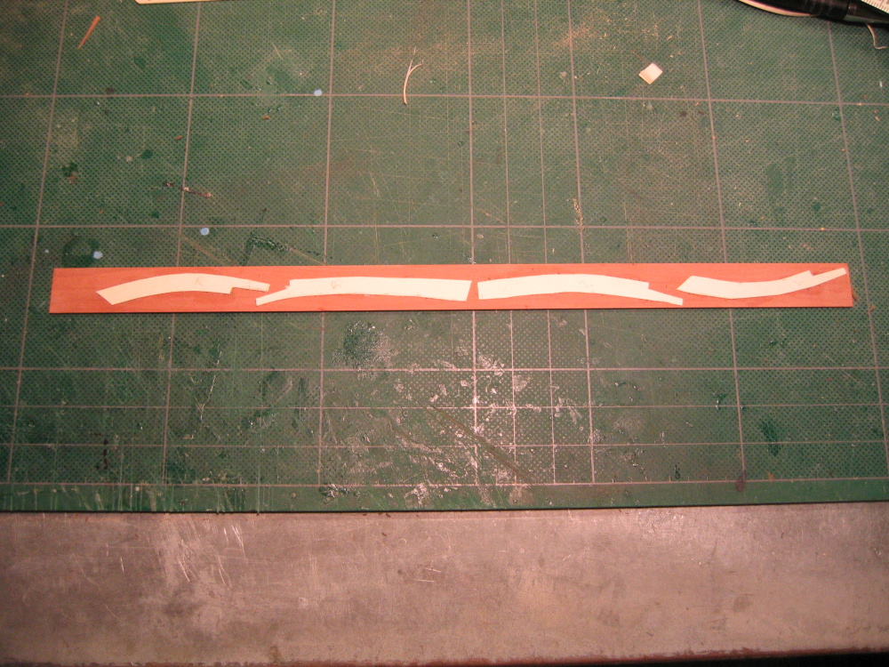
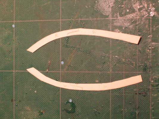
Then because of the severe curve of the bow, each template was divided into two with a scarf joint just like the actual boat. The templates were then rubber cemented to 3/64” x 5/8” swiss pear stock

-
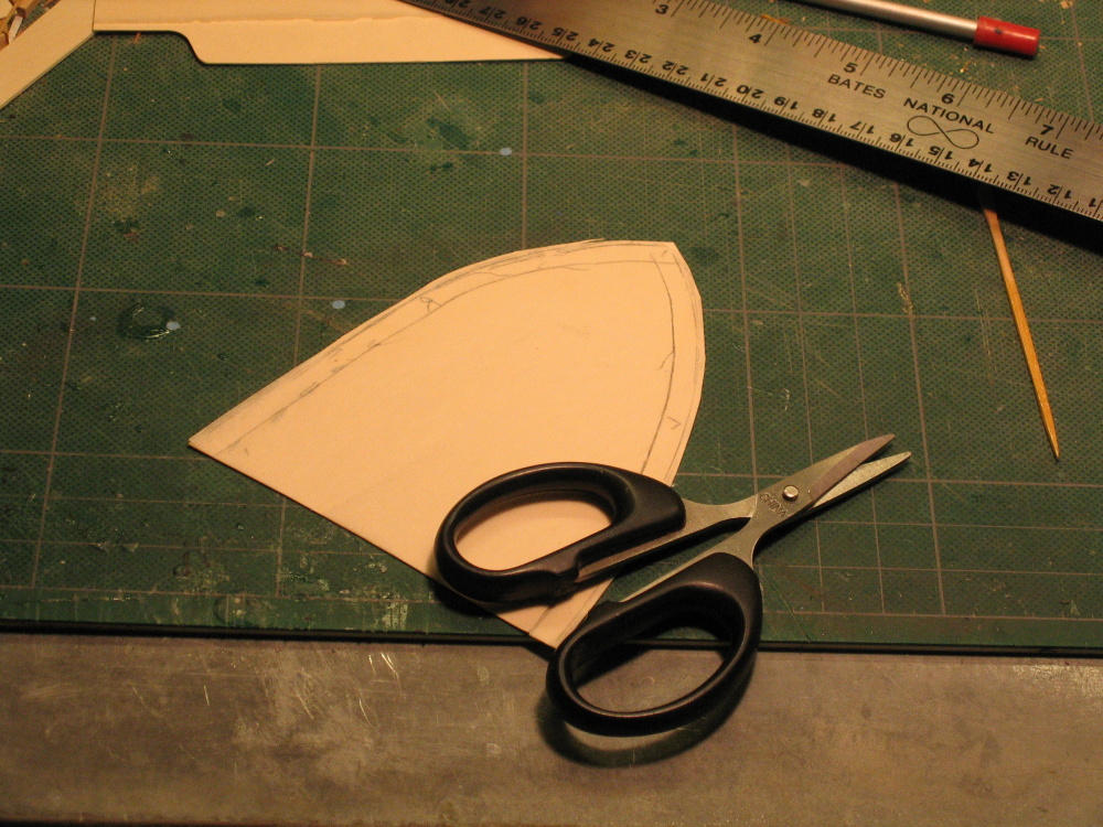
Forecastle Rails This constructed just like the quarterdeck rails. A tracing is made of the outer edge of the hull. Because the outside edge of the rail overhangs the hull by 1/32” the card stock was cutout with the extra thickness on the outside edge. The inside edge is measured about ¼” inside as a parallel line to make the initial templates. The tracing was then rubber cemented to card stock and the excess stock was trimmed and fitted to the bow.


-
Thanks Russ & Martin. I'll use what came with the kit and buy any additional ones if the need arises.