JSGerson
-
Posts
2,606 -
Joined
-
Last visited
Content Type
Profiles
Forums
Gallery
Events
Everything posted by JSGerson
-
 You are correct, those are the fun things to make. The gun deck has lots of these gem mini-models to fabricate. Too bad very few of them will be visible enough for observers to see and appreciate fully. Jon
 -
USS Constitution by mtbediz - 1:76
JSGerson replied to mtbediz's topic in - Build logs for subjects built 1751 - 1800
If I have a picture, I will share it. Just ask. Jon -
I think I read somewhere (and I could be wrong) that the brass railings were installed when the ship was converted into a Receiving Ship/Barracks in the late 1800s. I believe the hand ropes for the ladders were always there. Jon
-
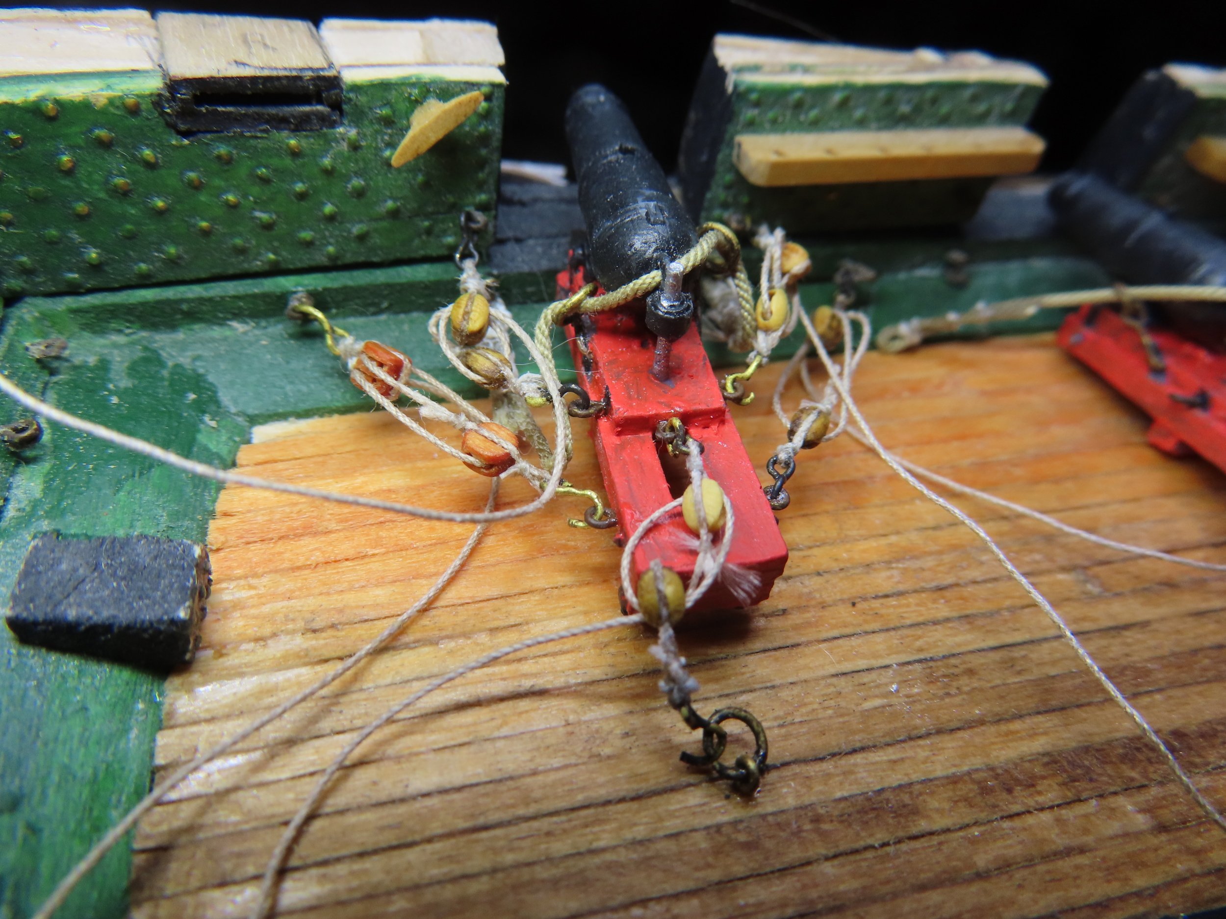
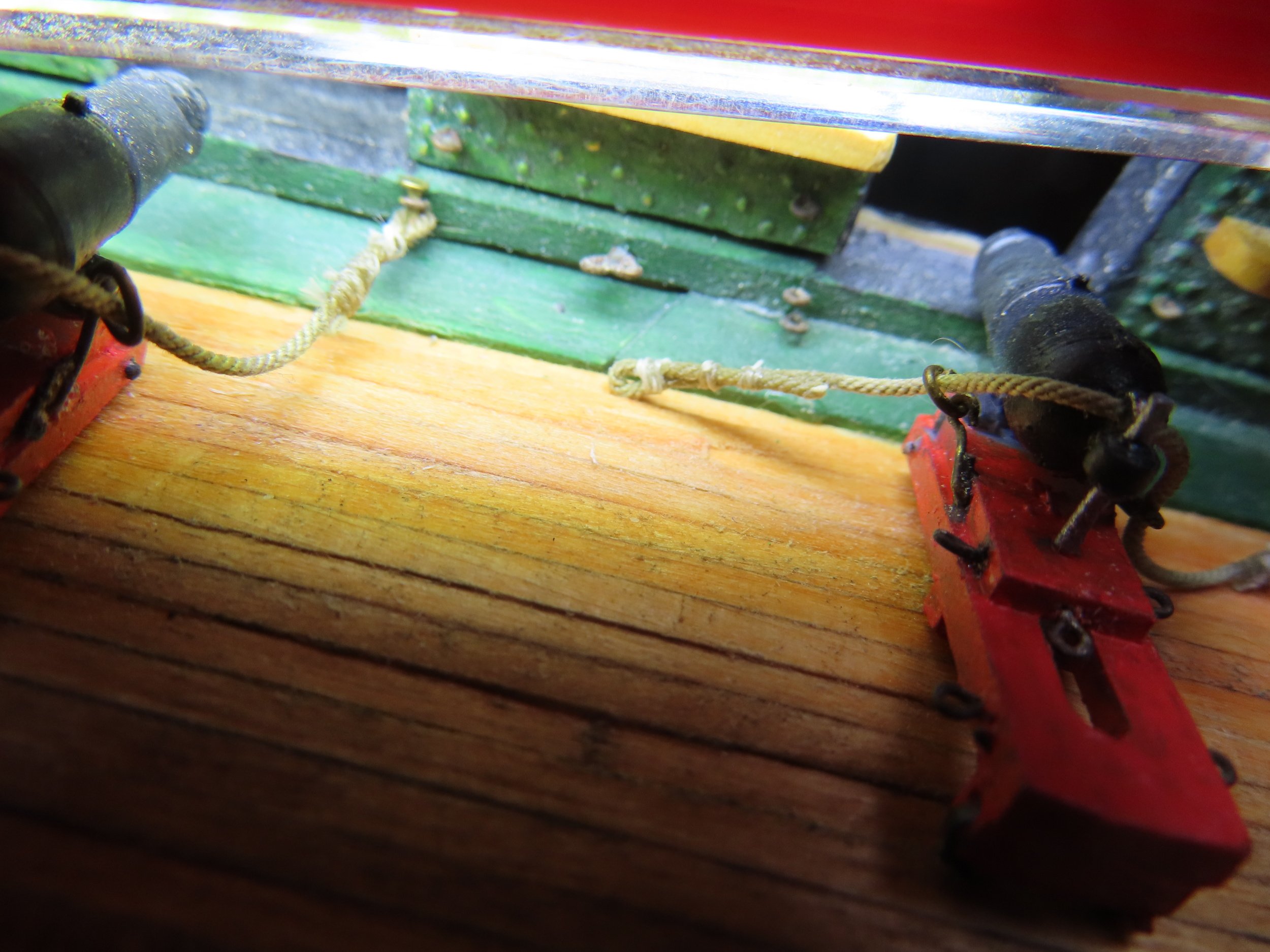
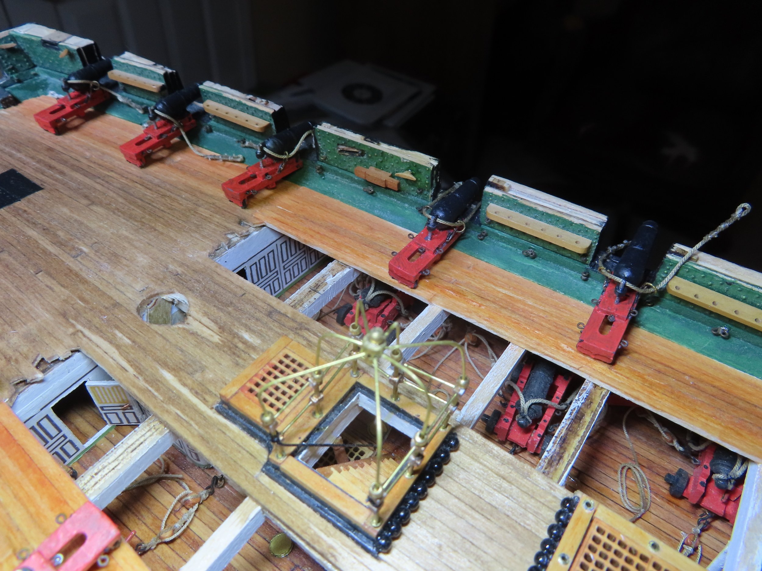
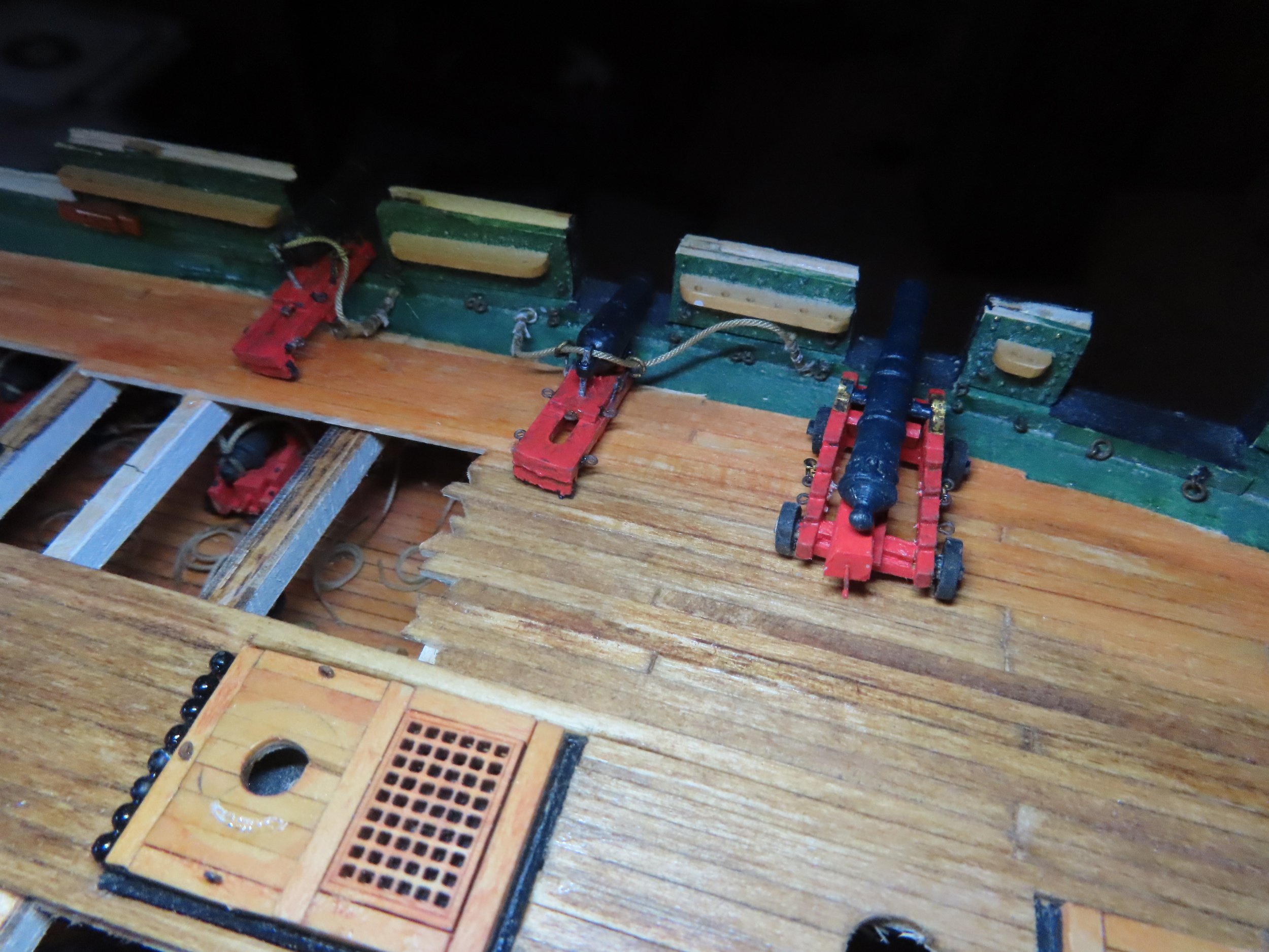
I then went on and added the remaining tackle. At this point, nothing is glued in place, and the lines are not neatly coiled up and positioned yet. The last three guns on each side of the stern will have a fifth tackle to pull back the gun slide where the spar deck is not cut away as seen in the last photo below. This last tackle is not installed on the actual ship as they are tourist tripping hazards in the modern world.
-
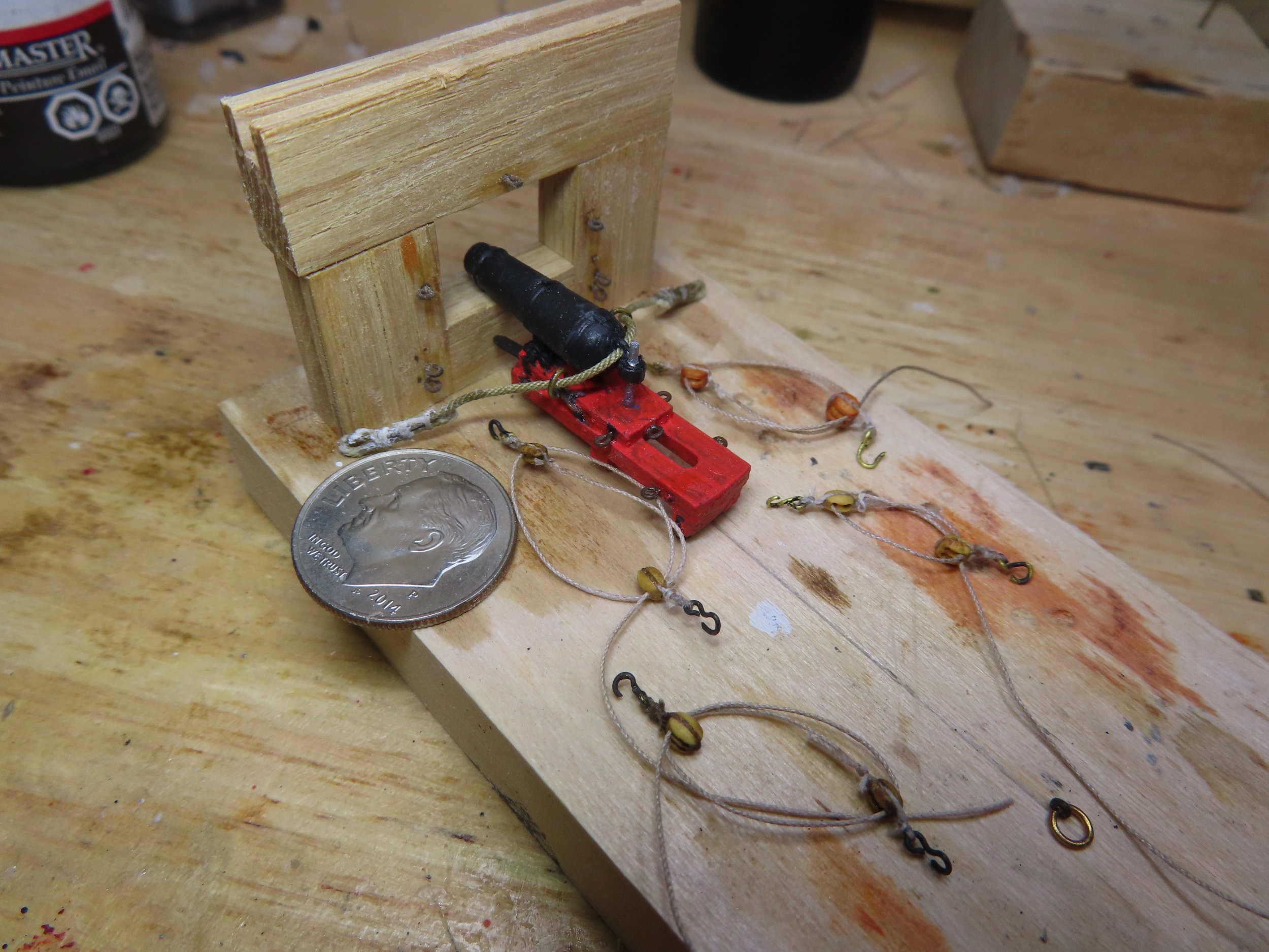
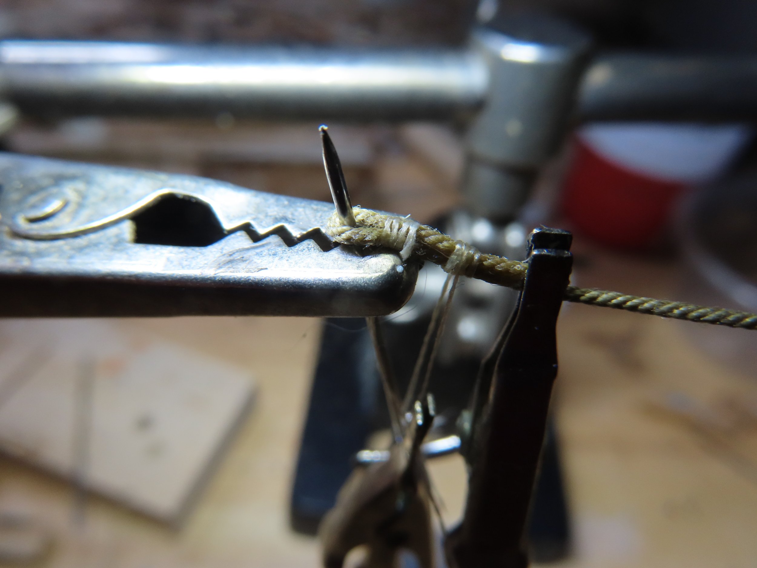
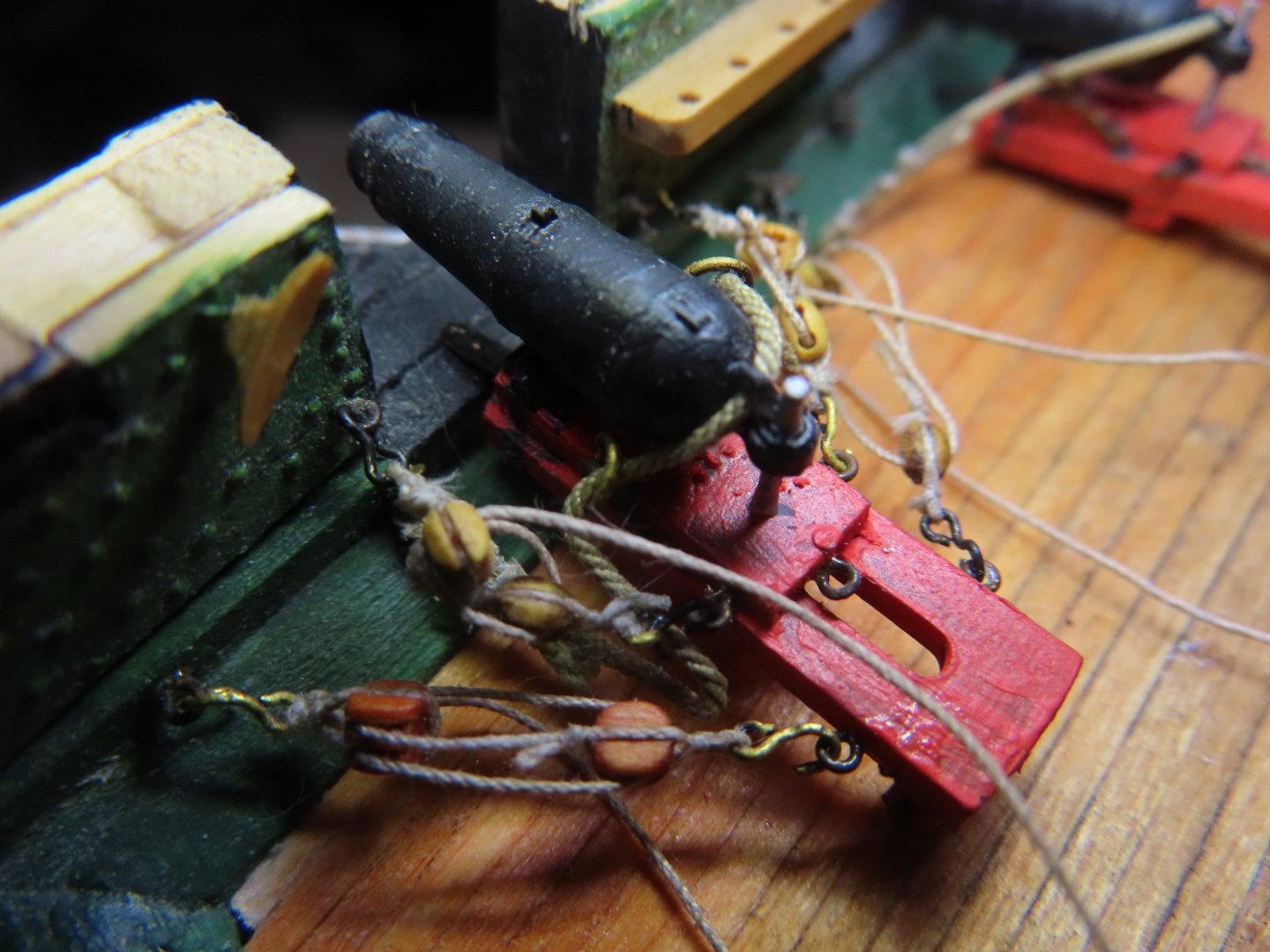
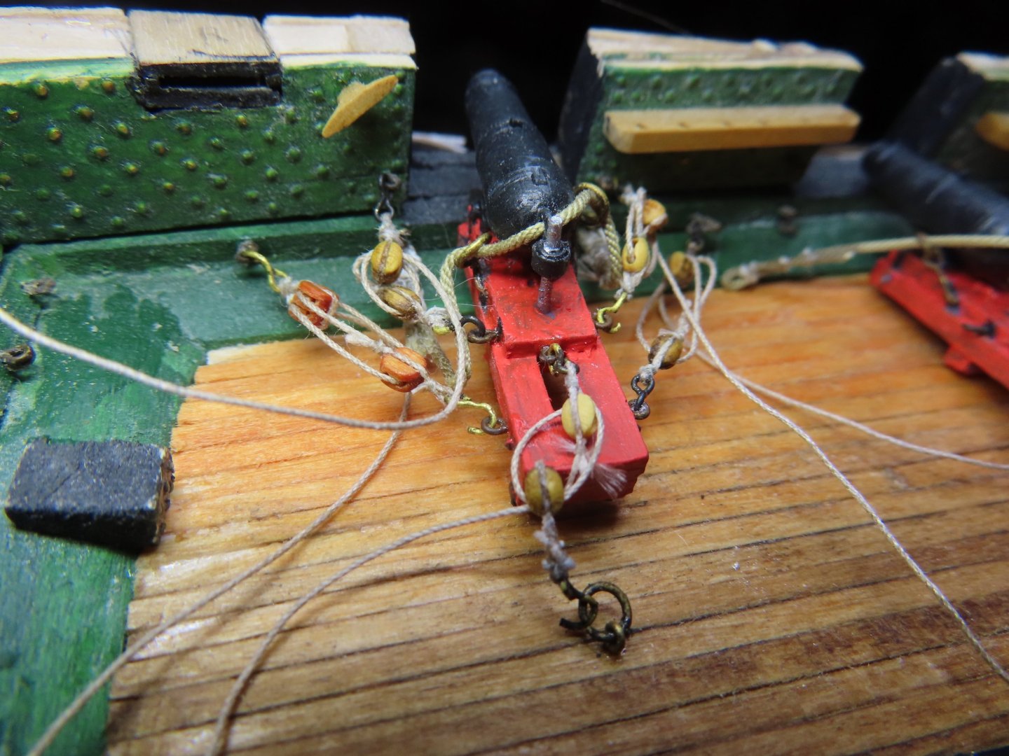
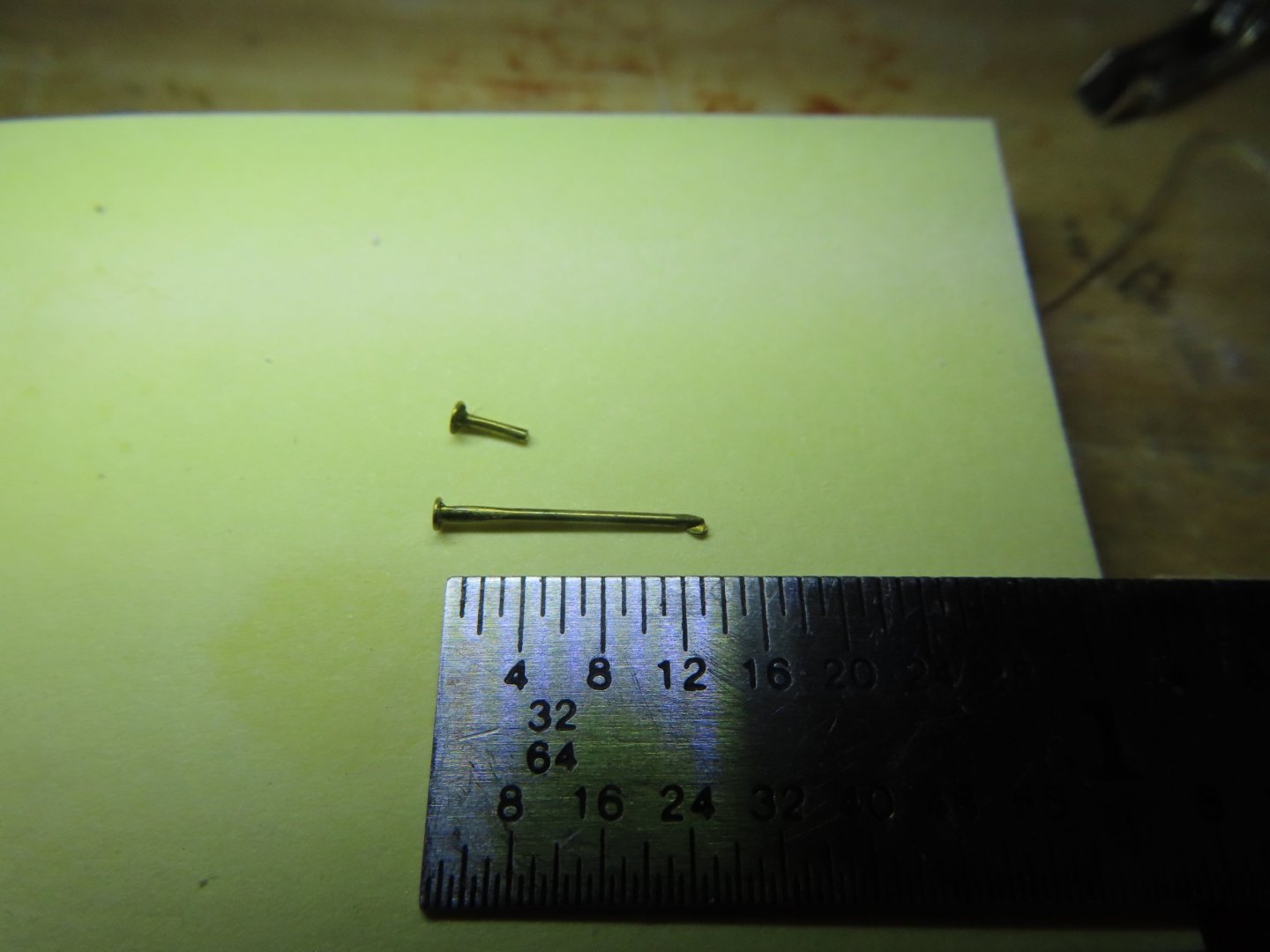
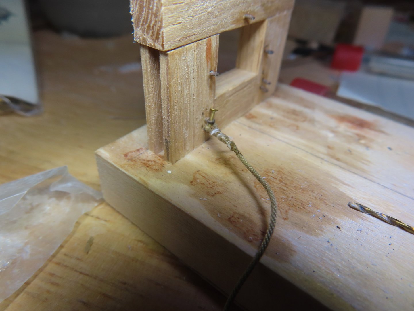
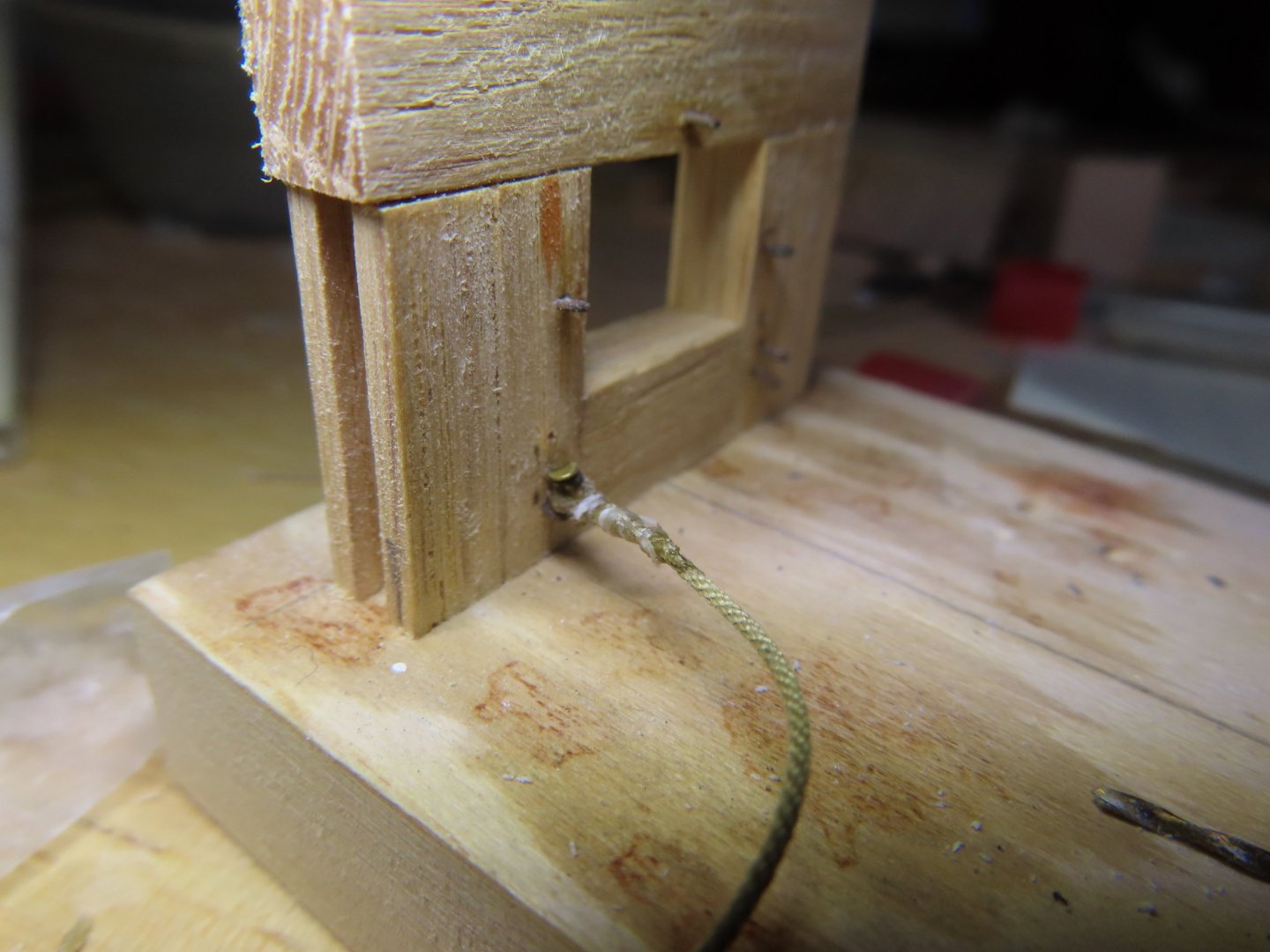
As is my masochistic custom of following the more difficult path, I chose to attach the recoil rope to the bulwark like I did on the gun deck by inserting the rope loop between two eyebolts mounted one above the other when the bulwarks were installed many years ago. Then a short drop bolt is inserted into the top eyebolt, though the rope loop, and out the bottom eyebolt. The drop bolt was made from a 3/8” long 0.025” shaft diameter flathead nail which was cut to 1/8” length. I apologize for the out of focus image. A zero depth of field, in a confined space, with a shaky hand are not a good mix. I didn’t realize I had a poor-quality photo till I was composing this post. So, I demonstrated the process using my gun port mockup.

-
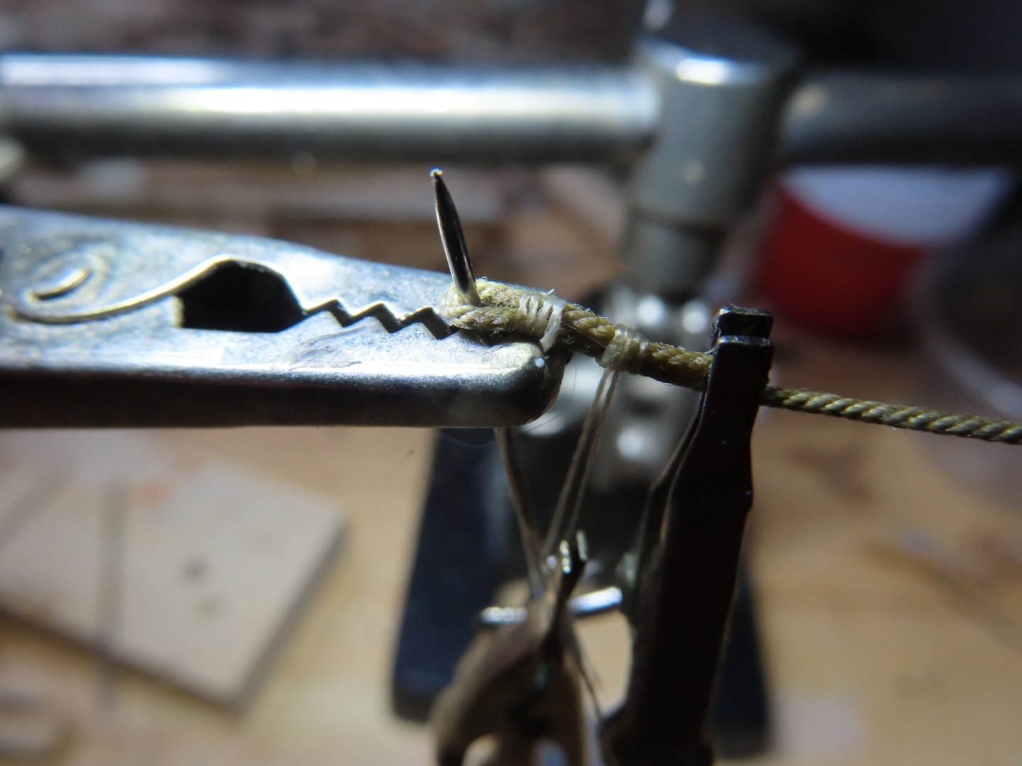
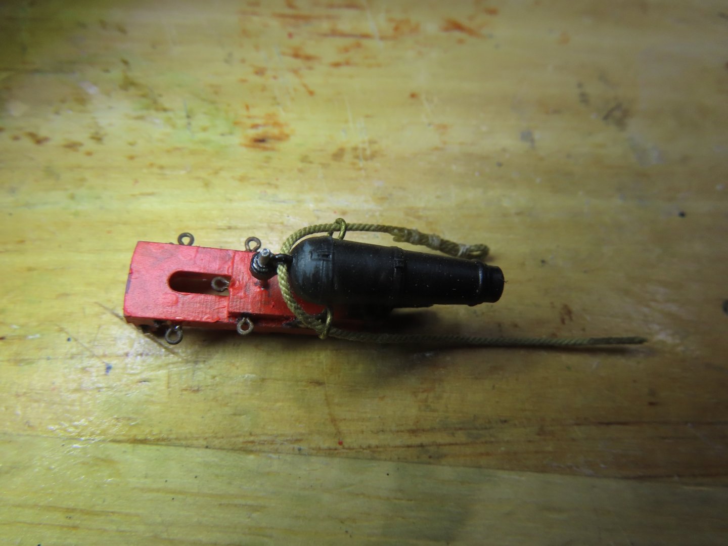
Using the mockup gun port I originally made for the gun deck; I fabricated the recoil rope and a set of typical tackles. The blocks, both single and double were 3/32”, the tackle rope was tan 0.008” (0.028 mm), and the recoil rope was Ultra tan 0.030” (.76 mm), all from Syren Ship Model Co. As previously mentioned in the prior post, the seizing line was the 3/0 nylon rigging line from the kit. Once I was happy with first completed set, I made just the recoil ropes for all 20 carronades first. While seizing the loops, I noticed quite quickly that the loop would not pass through the recoil rings already attached to the guns. The rope loops were just not flexible enough at this scale. Therefore, after seizing the first loop, the recoil rope was threaded through the rings on the gun with the “un-looped” end first. Then the free end was seized creating the second loop.


-
It is fascinating to watch you assemble the historical pieces you have accumulated and translate them into your model. I can't wait for more posts. Jon
- 233 replies
-
- 1
-

-
- Model Shipways
- constitution
- (and 5 more)
-
So far, so good. Jon
-
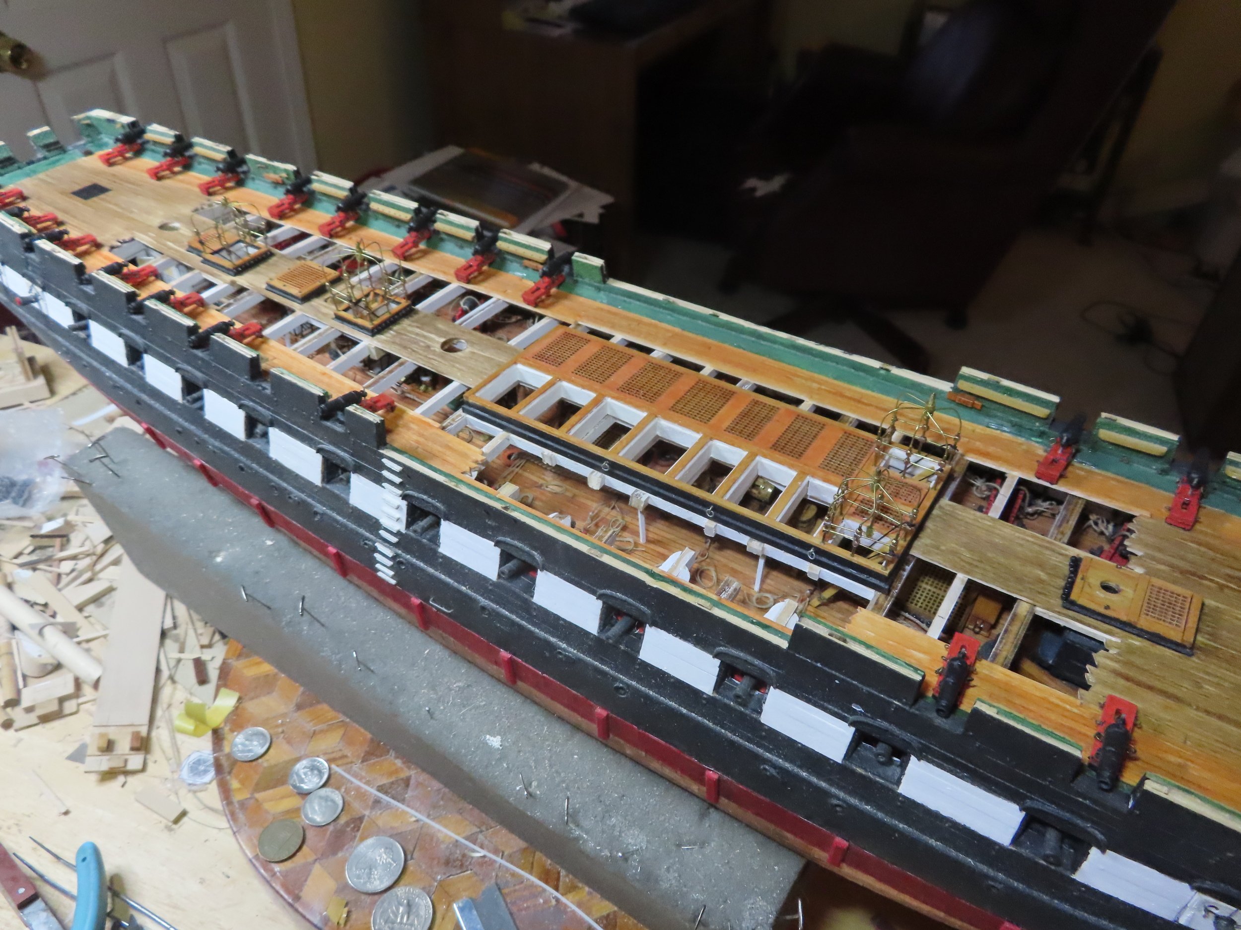
I have completed the gun deck on my model and followed the photos of the real ship for fastening the ropes and tackles to the bulwarks. I am doing the same thing for the spar deck now. It was a little tricky to attach the recoil ropes between two eyebolts and adding a pin to lock them in place, but I made it work. If you are going to seize your block and tackle directly to the bulwark eyebolts, DO NOT attach the eyebolts to the bulwark first. It will be a b*tch seizing the lines to the eyebolts on the model. Seize the lines to the eyebolts off-ship, then insert the eyebolt with the attached tackle into bulwark. Personally, IMHO, I believe the use of hooks would have been more practical on the ship for quick and easy replacement when it was required. Jon
-
Well done! And I love your sense of humor. I bet you have the only model of the USS Constitution demonstrating the use of the "seats of ease."🤣 Jon
-
USS Constitution by mtbediz - 1:76
JSGerson replied to mtbediz's topic in - Build logs for subjects built 1751 - 1800
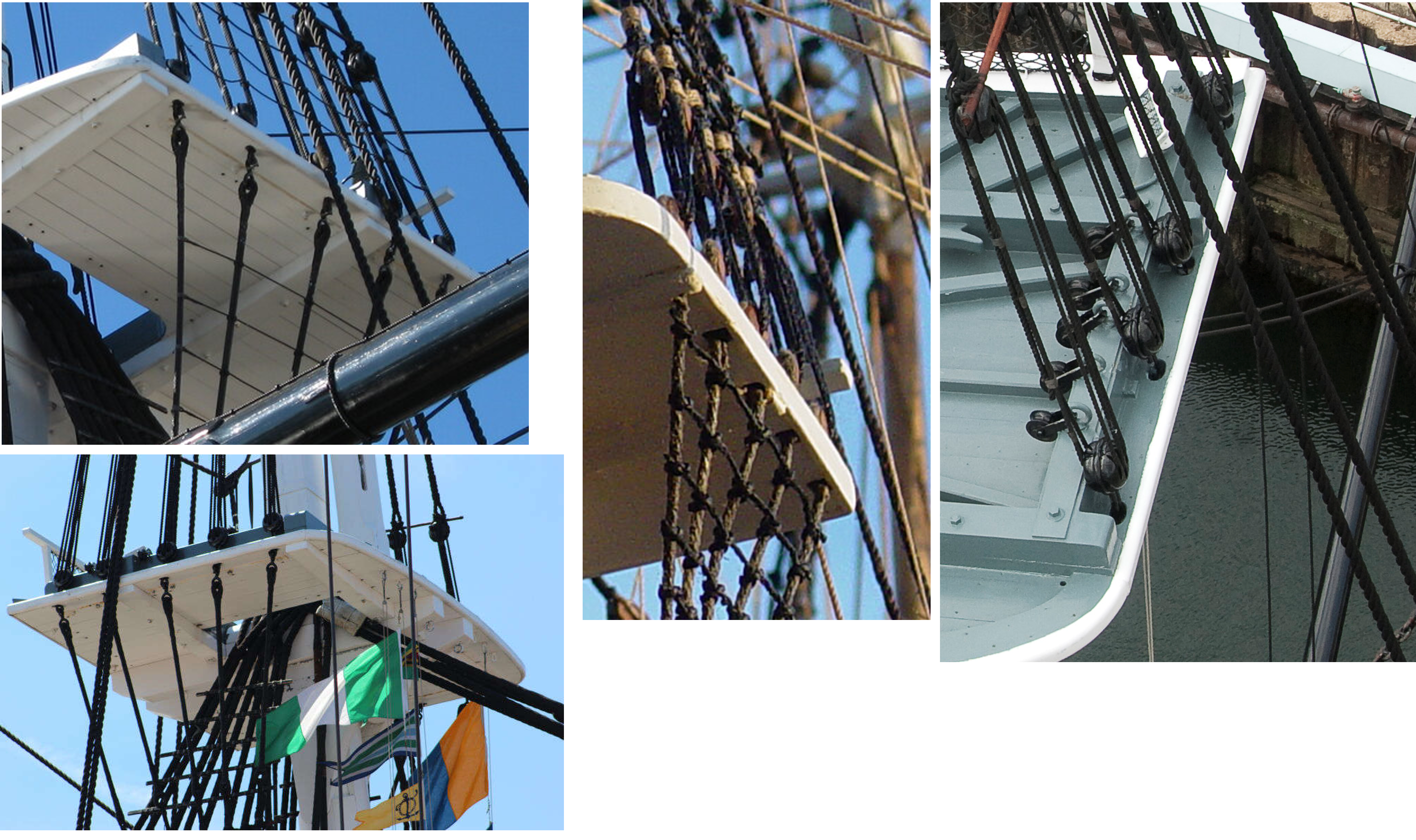
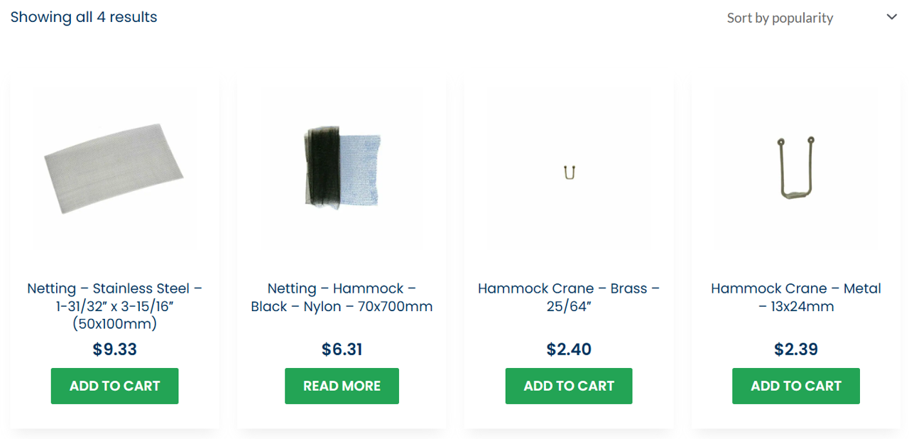
The main thing I don't like about tulle is that it is not a true cross net. If you look closely, the intersections of the lines forms a star pattern. Of course, you would have to be up real close and be wither very near sighted or have a magnifying glass so the model builder can get away with it. I have found ship blogs where the builders weave their own nets. If anyone is interested, I can point you to them. Then there is the alternative: Steel mesh. Model Expo offer one but does not indicate the dimensions of the mesh squares Modeler Central (Australia) I have not used either one Jon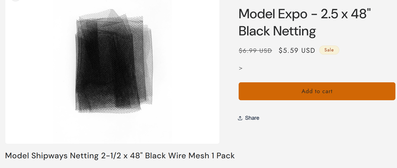
-
Beautifully done! Jon
-
USS Constitution by mtbediz - 1:76
JSGerson replied to mtbediz's topic in - Build logs for subjects built 1751 - 1800
That is some jig you made. It worked perfectly! Jon -
USS Constitution by mtbediz - 1:76
JSGerson replied to mtbediz's topic in - Build logs for subjects built 1751 - 1800
Those are some exquisitely clean cut notches on those trestle tree components. As always, a pleasure to see your workmanship. Jon -
Very handsome model! Jon
-
For me, the enjoyment is in the journey and this model has a multitudes of side trips, some seen by others, others not so much. Once the project is finished and on display, the fun, for the most part ends. My journey so far. is 8 years and still running😁! Jon
-
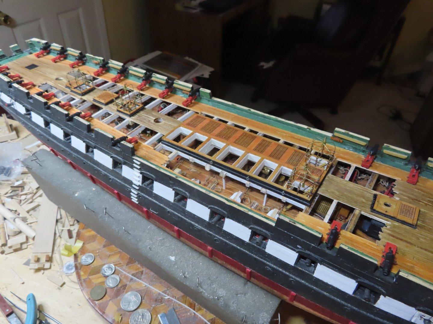
I too built the gun deck with a bunch of details. I made them somewhat visible by removing some of the main hatchways, spar deck planking, and beam supports. However, even with openings, a lot of the gun deck details are still obscured. Only me and the man upstairs know they are there. The image below shows the present state of my model. Jon
-
USS Constitution by mtbediz - 1:76
JSGerson replied to mtbediz's topic in - Build logs for subjects built 1751 - 1800
It's good enough for me too. I LIKE it! Jon -
It's looking grand!!! Jon
-
A very neat, clean, and viable solution. Well done. Jon
-
Well, it looks like you jumped into the deep end of pool!!! Enjoy!! Jon
-
USS Constitution by mtbediz - 1:76
JSGerson replied to mtbediz's topic in - Build logs for subjects built 1751 - 1800
If you look closely, drilling holes is the way to go. They don't look constructed like the method the channels used. Jon -
USS Constitution by mtbediz - 1:76
JSGerson replied to mtbediz's topic in - Build logs for subjects built 1751 - 1800
I can't speak for Mustafa's model but technically, the deadeyes on the actual ship are not attached to the tops at all; but pass through openings in the tops and attached to the Bentnik Shrouds below. Jon
-
I have seen it, but think it may just be too big at the scale we are working at. I can barely use fine needle tweezers, so I just tie a simple knot with the seizing line, wrap 2 or 3 times and tie another simple knot. Then I add a fine drop of CA glue to finish. For me, that tool makes sense for larger scales. Jon
-
Frank. you might be able to make the hook style I used using a thinner gauge for your 1:96 scale, but I think you would also lose strength with such a fine wire. And I not even talking about line seizing. I would simplify the process. Getting blocks smaller than 3/32" is going to be tough and adding a hook, tougher. When I made my 1:64 scale Rattlesnake, I wasn't as cognizant of the block rigging details, so I drilled a fine hole into the block and inserted/glued a straight shaft hook into the hole and skipped tieing the hook to the block. Wrapping the rope line around the block was made easier, neater, and no layman was wiser. Jon