Check out our new MSW Sponsor Innocraftsman
×


JSGerson
-
Posts
2,603 -
Joined
-
Last visited
Content Type
Profiles
Forums
Gallery
Events
Everything posted by JSGerson
-
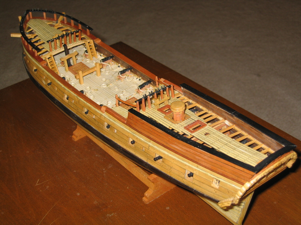
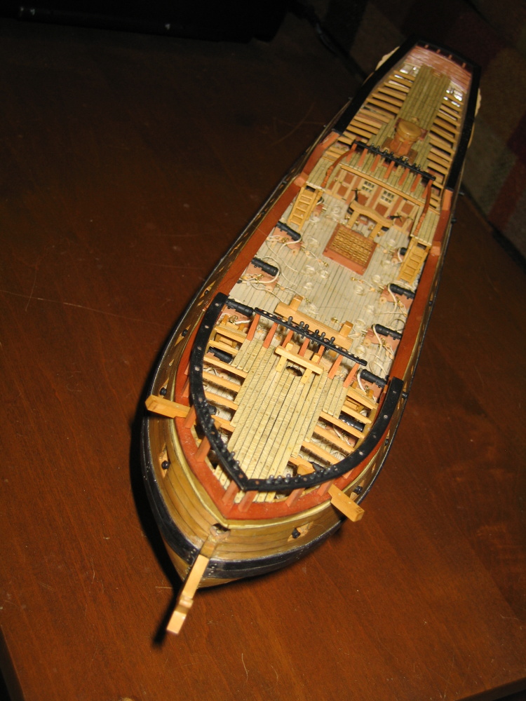
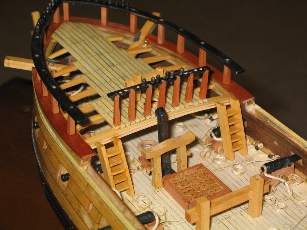
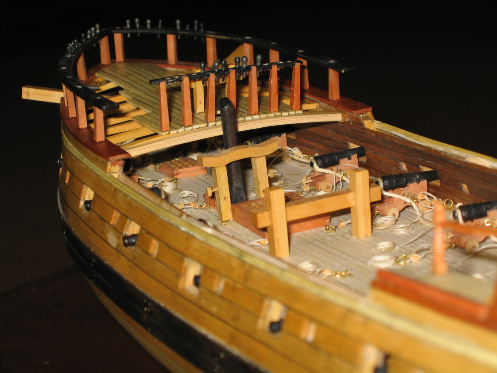
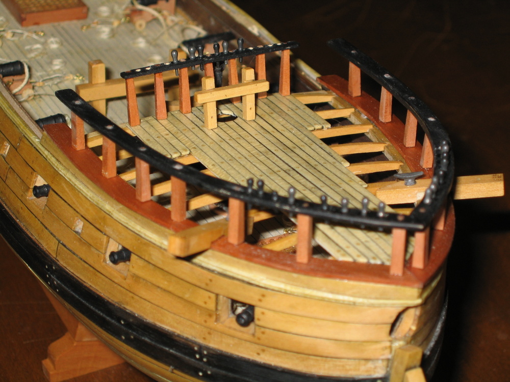
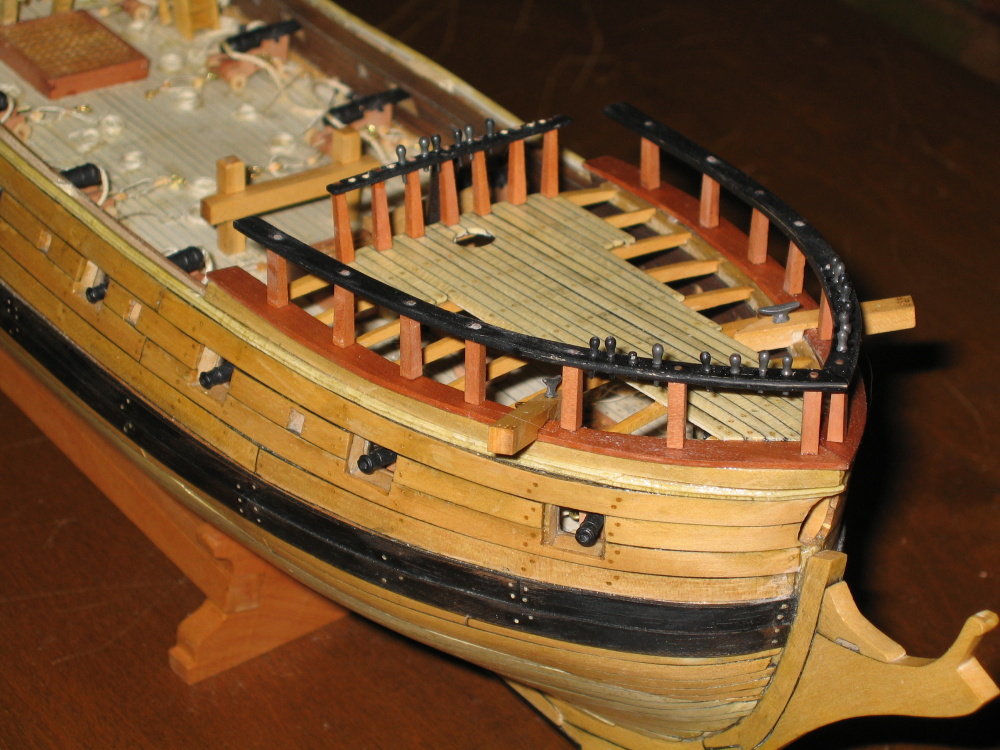
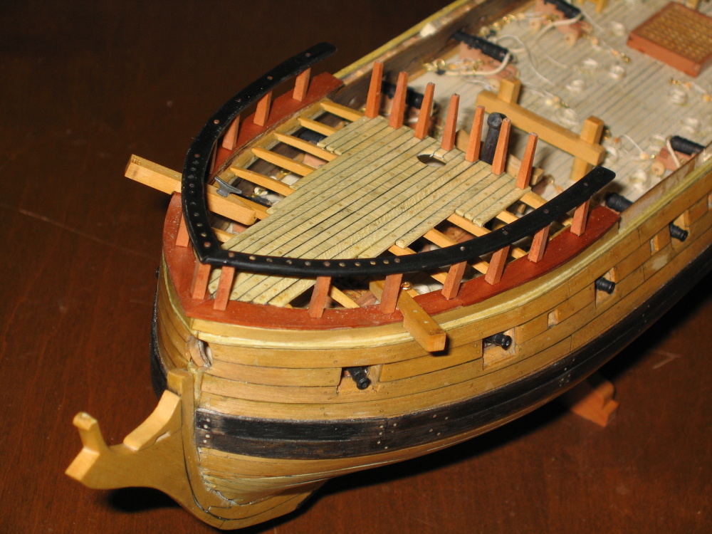
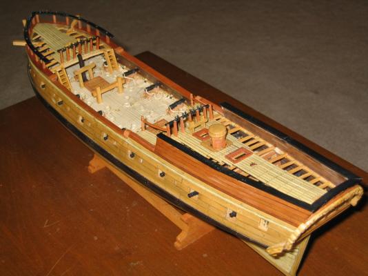
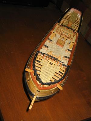
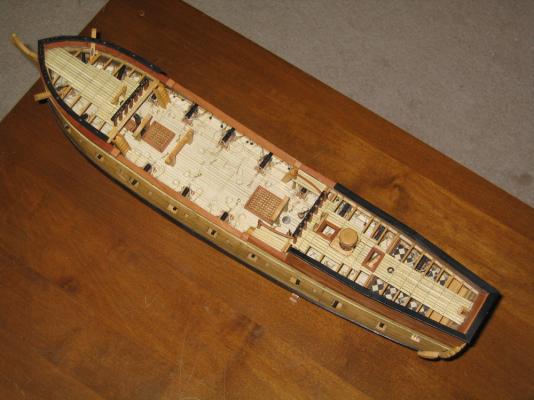
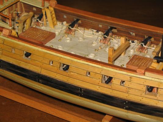
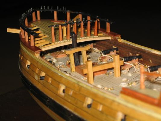
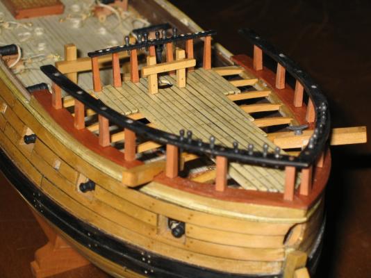
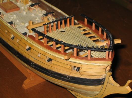
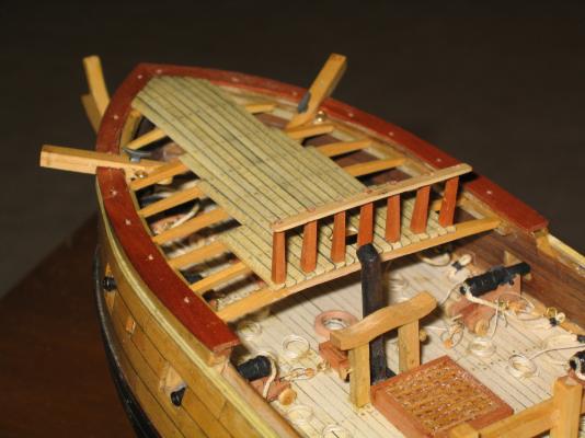
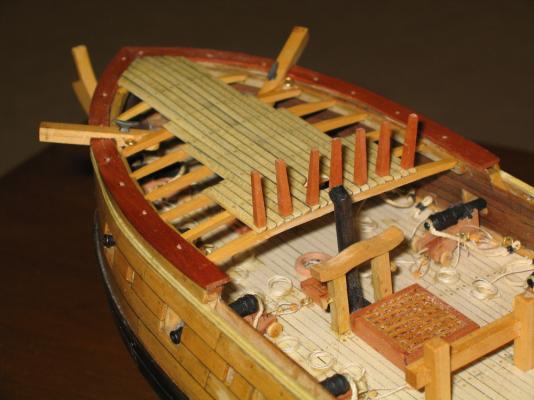
 End of Chapter 8 Here is what the model looks like at this stage
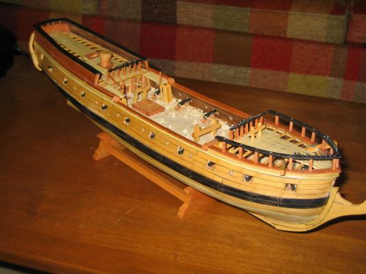
-
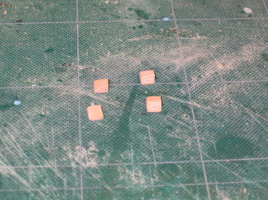
They were glued on and then a coat of wipe-on poly applied
-
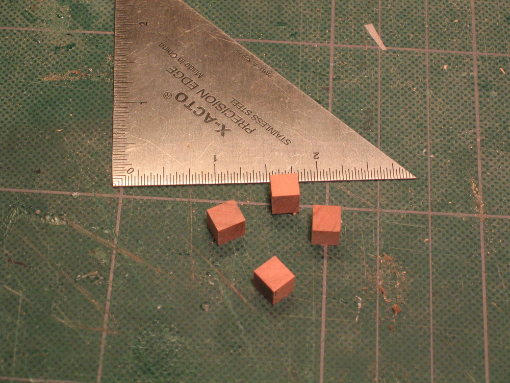
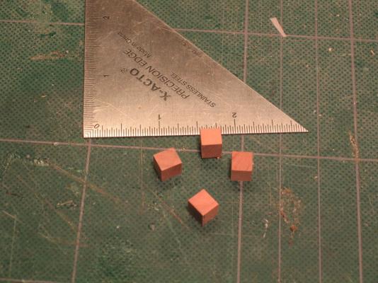
Using scraps of swiss pear from the construction of the cannon trucks I fashion four ¼” cubes from which to carve the hances. (Remember, per the Practicum these were supposed to be put in when the gangplank was finished. At that point I explained why I didn’t) Once more my lack of experience has lead me to compromise. It turns out I did not pay attention to the angle of the rails in relationship to the deck. The waist rails should have been parallel to the forecastle and quarterdeck rails. Mine weren’t. As a result the hances are taller on the inside face than they are on the outside. The carvings were done to look like swirls. The Practicum claimed that the forward hances didn’t have any carvings on them, but per Hahn’s plans, you can’t tell as that area is covered with other detail. So I carved them to match the aft hances.
-
Before they were glued to the bulwarks, I glued some pieces of scrap wood inside and flush to the top of the walls to provide a solid gluing surface for the rails.
-
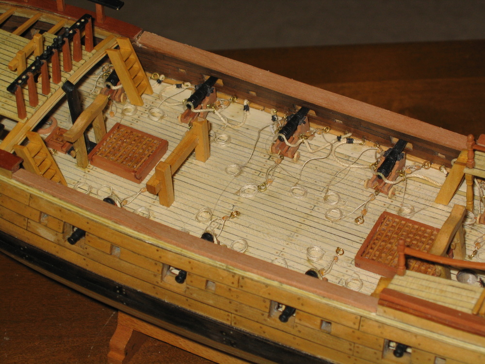
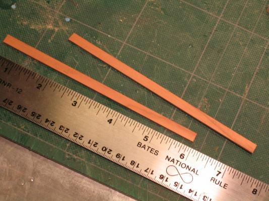
Main Waist Rails The main waist rails are made from two pieces of 1/16” x ¼” swiss pear. They were cut to length and trimmed as they narrow a bit at the ends. This was done with a series of dry fits.
-
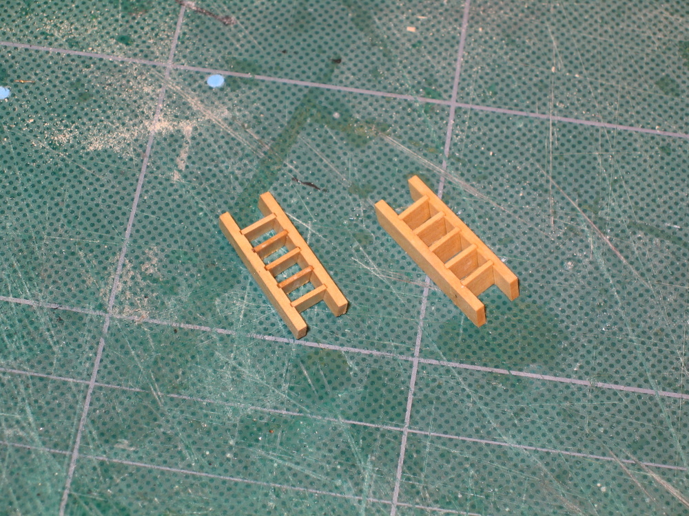
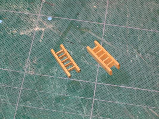
Forecastle Ladders Ahh the ladders…again. These ladders, the fifth and sixth ones now, were made the same way as the quarterdeck ladders were done so I have had a little practice. I looked around for a nice simple ladder making jig, but they seemed more effort than I thought worth it for these last two ladders. Using the Brynes saw and meticulous measurements, I was able to produce the required slots in the ladder sides with the proper width, depth, and spacing. The saw blade was 1/32” thick exactly the thickness of the steps which meant I had to sand the steps a bit to allow them to slide into the slots. After moving a few cannon ropes, they were glued into place.

-
Forecastle Edge Piece Like the quarterdeck, I interpreted Harold Hahn’s plans to indicate there was an edge piece going from one deck clamp to the other for the forecastle. The Practicum did not address this at all. I have noted in other models, the maker did install it on theirs, so I did on mine. I was made in the same fashion as the quarterdeck
- 974 replies
-
- 1
-

-
- rattlesnake
- mamoli
- (and 1 more)
-
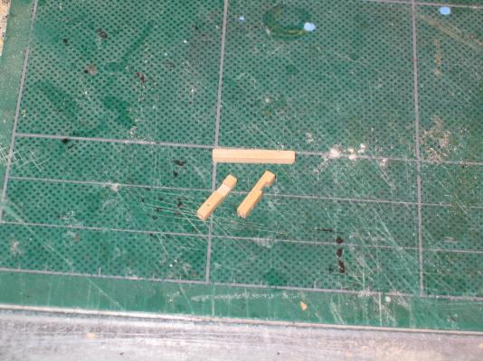
Forecastle Deck Bitts The forecastle deck bitts were made in the same manner as the brace bitts on the quarterdeck from 3/32" square boxwood. They are the same height. The only difference between these and the brace bits is that the measurement from the ends of the cross piece was 5/32" instead of 3/32".
-
I just ordered the MS plans - $12.50.(plus shipping $8.99) I finally got my sale!!!
-
Thanks for the picture. I really don't think the cleats are that important. It seems that everybody's model are a bit different for each other and who is to say which is correct. Ships change over time due to captain's whim, use, battle damage, and plain wear and tear. If I have to install them some time in the future, I could do it your way and place the cleats on the deck or smooth off the bottom (to avoid drilling) of the cleats and use just a fine dab of epoxy to apply it to the stanchions.
- 974 replies
-
- 1
-
-
- rattlesnake
- mamoli
- (and 1 more)
-
Since I don't have the MS plans yet (I'm still waiting for a sale that applies to them) I tried looking at the models that others have made for those cleats, especially MS models. I have images from 44 different models, 7 of which I know are from the MS kit. Of those that showed clearly the forecastle I couldn't get a clear view with enough detail to make out the referred cleats. Actually I'm not quite sure if you are referring to the forecastle center rail of the the Top Rail. In either case I couldn't see the cleats. Neither the Mamoli or the Hahn's plans show them as you have stated. If I add them, I'll have to wait until I get the MS plans.
-
Belay Pins Although the Practicum doesn't call for the belay pins to be installed at this stage, I thought it wise to do so while it was still free and clear of any other items that may be in the way later. The belay pins were insert and glued to the forecastle top rails. It was at this point I realized that I had forgotten to drill the belay pin holes in the forecastle center rail. Well, it wasn't done for the quarterdeck center rail and I had to drill those, so I hoped it wouldn't be too big a problem now. I marked to position for the holes with a pin and drilled pilot holes for eight pins in the quarterdeck center rail figuring the rail is a delicate structure. I didn't want to put too much pressure on it. Then I drilled the holes again so that the belay pins would fit. Surprisingly, this worked without a hitch. Once the forecastle center rail was solidly glued, the same process was repeated only this time there were only six belay pins according to the Practicum. What was weird here is the Practicum showed all three pins (per side) in between two stanchions. The Mamoli plan showed two pins. I went with the Mamoli plans because three pins seemed a bit crowded and two pin holes between stanchions also matched the quarterdeck center rail. I installed only six belay pins as per the Practicum. If need be I can install more as the holes for the pins have been drilled.
- 974 replies
-
- 1
-
-
- rattlesnake
- mamoli
- (and 1 more)
-
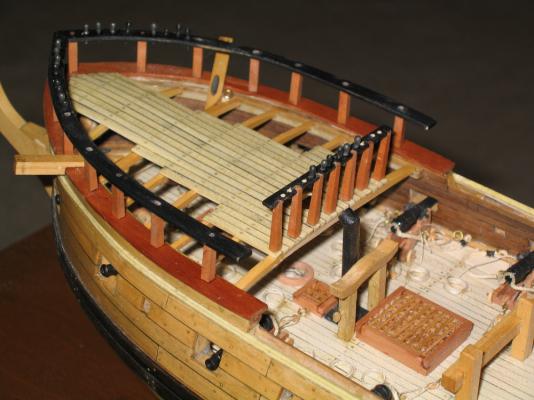
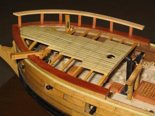
And before the CA glue completely set, both completed rail assemblies were installed onto the bow. This allowed me a little wiggle room to insert the brass pegs on the bottom of the stanchions into the holes on the bow and make any necessary adjustments. While the CA glue for the forecastle top rails was setting up, the forecastle center rail was installed.

- 974 replies
-
- 1
-
-
- rattlesnake
- mamoli
- (and 1 more)
-
The Forecastle Top Rail - Final With the forecastle top rail now dry, the stanchions were installed to the rails.
-
The rail was cut to length and notched just like I did for the quarterdeck center rail. It was then dry fitted to ensure proper installation. It was then painted black.
-
Forecastle Center Rail While the rails were drying, forecastle center rail stanchions were finally installed. You may remember I made those at the same time as the quarterdeck center rail stanchions.
-
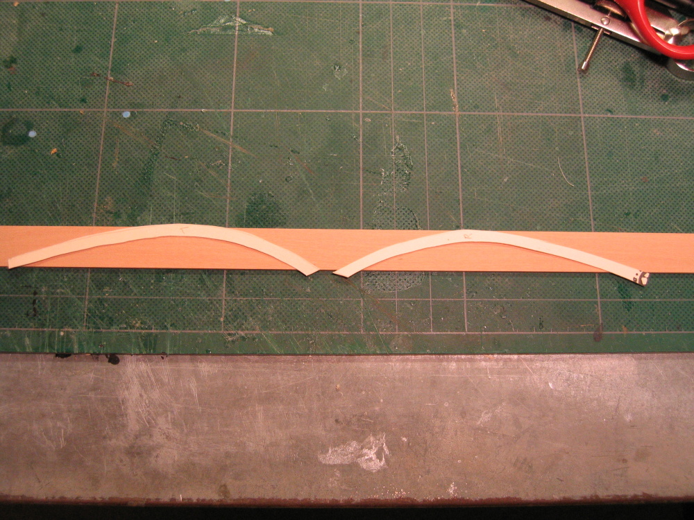
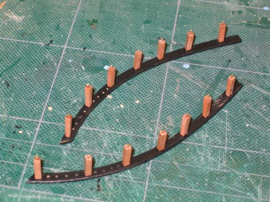
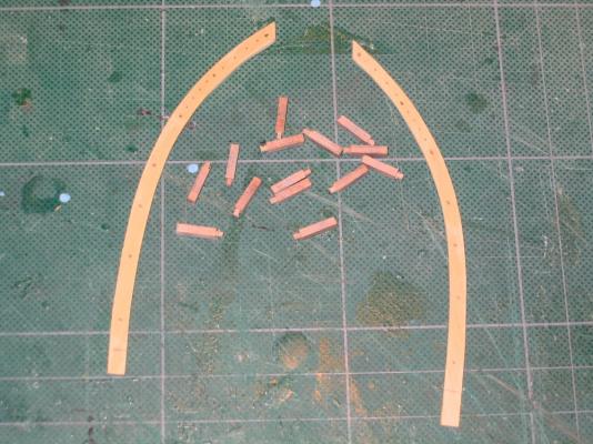
The assemblies were removed, disassembled, and although the Practicum did not call for it at this stage, the remaining belay pin holes were drilled into the rails. The number of belay pins on the forecastle top rail as well as the placement of the rail stanchions turned out to be a bit of a mystery. Depending on which plan and numerous models I looked at, the number of pins as well as the placement of the rail stanchions varied. Not knowing who was correct I went with the Hahn’s plans for the stanchion placement. Since both the Mamoli plan and the Practicum used 8 belay pins on each side I made 8 holes. Mr. Hahn’s model had 5 pins. From the photo’s I’ve seen of the Model Shipway official model, it appears it has 13! I don’t know for sure since I don’t have those plans…yet. Anyway, after the holes were drilled, the rail top edges were round off, sanded, and then the rails were painted black.
-
You will notice in the image of the rails above there are markings for drilling the stanchion tenon and belay pin holes. First the stanchion holes were drilled and dry fitted with the stanchions. This in turn was dry fitted to the bow. The image below shows just the starboard. The same was done for the port side.
- 974 replies
-
- 1
-
-
- rattlesnake
- mamoli
- (and 1 more)
-
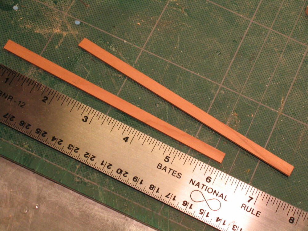
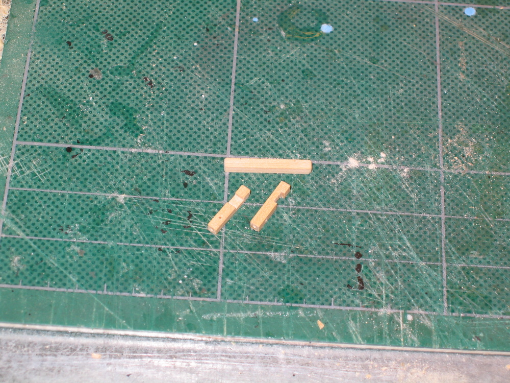
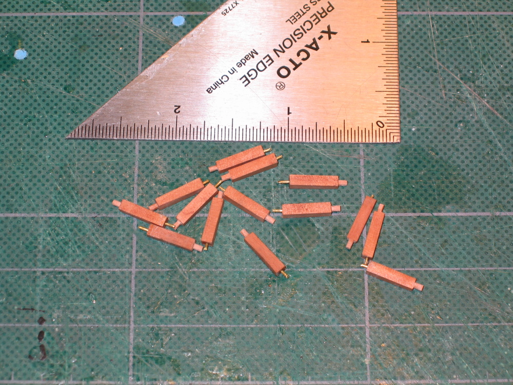
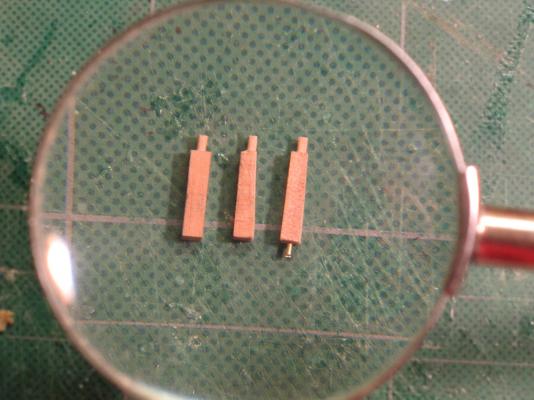
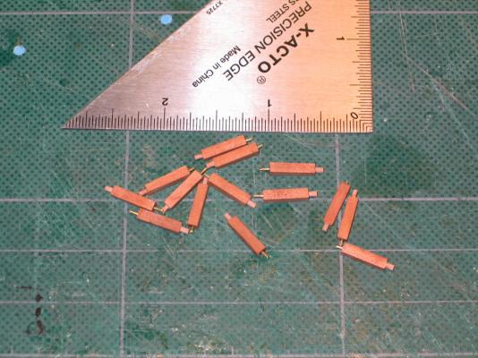
After looking more closely at Harold Hahn’s model (and others) I noticed that contrary to Mr. Hunt’s model, the stanchions’ top tenon does in fact show flush on the surface of the rail. The Practicum would have had the tenon shorter so that it didn't show at the rail surface. Because I thought you shouldn't see the tenons I initial chose to use brass wire pegs. Since I found that is not necessarily the case I will make the tenons for the top and use the brass pegs only for the bottom of the stanchions. The brass pegs will give me a little leeway when installing the railings. Using the 3/32” square stock I made earlier (see Fixed Gang Plank) I fashioned the fourteen ½” long pieces into stanchions. The tenons were made in the same fashion as the gun truck axles, one side was sanded to slope inward, and a brass wire was inserted in the bottom to create the plug. Notice my fancy macro lens in the second photo? The image was shot through a magnifying glass.
-
Everything is built and ready for installation. I'll be updating the log soon with all the gory details.
-
The Forecastle Top Rail Stanchions Once again I am going to deviate from the Practicum for the construction and installation of the forecastle rail stanchions. The Practicum instructs the builder to create 1/16” wide tenons 1/32” deep on both ends of fourteen ½”stanchions. However once the stanchions are installed, there will be no indication of this effort. Instead I plan to use brass wire like I did for the quarterdeck rail stanchions but at both ends for the deck and rails. It won’t look any different and should be just as strong and a whole lot easier to do…assuming I don’t screw up.
-
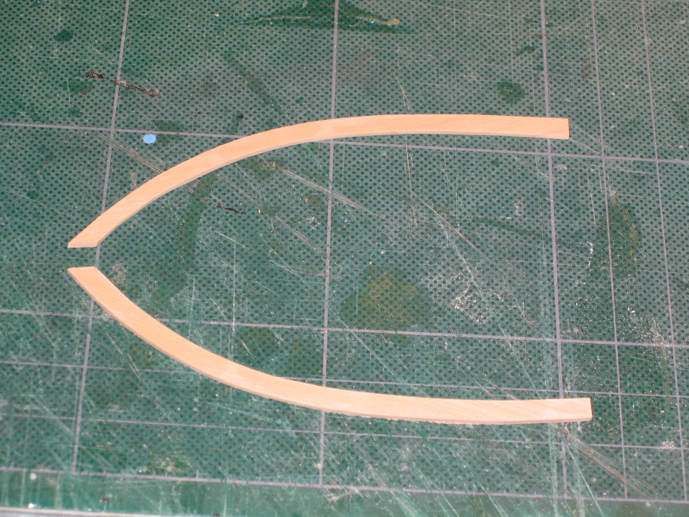
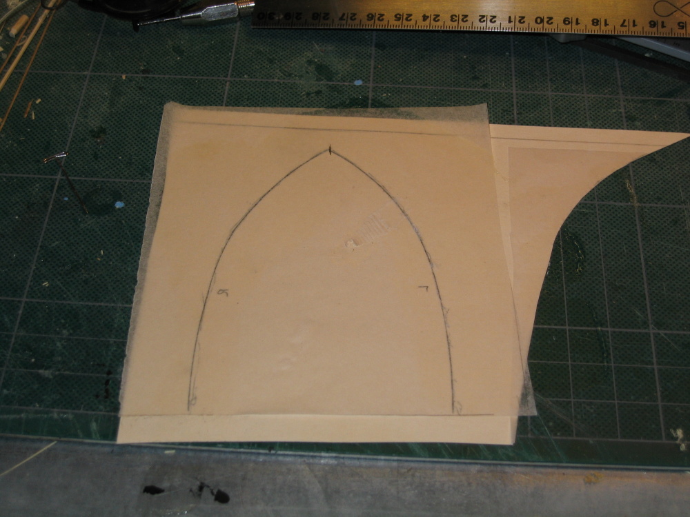
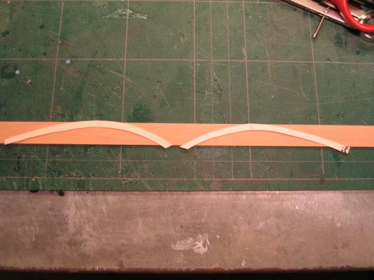
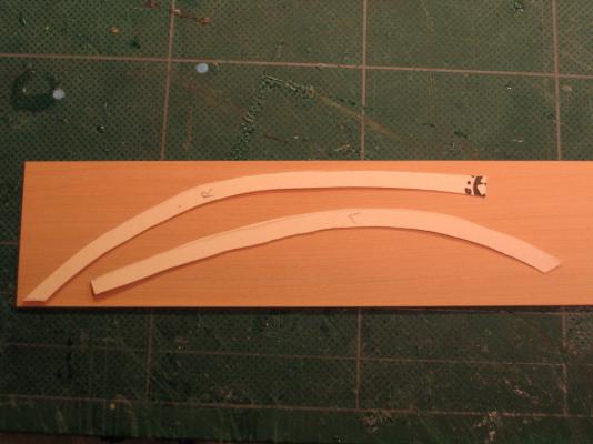
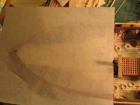
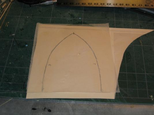
Although the Practicum would have you rubber cement the tracings directly to the wood stock, I cemented them to card stock. The inside curve was cut off and that edge was used as a guide for the compass to draw the outside curve. It was then rubber cemented to the stock wood. I just found it easier to do it this way. The railings were subsequently cut from the stock wood using the scroll saw, trimmed and sanded. The edges still need to be shaped, belaying pin openings still need to be drilled, and the whole railing will be stained black, but I’m getting a little ahead of myself.

-
The only problem was that the curved rail tracing did not fit on the5/8” width boxwood. It was too narrow (at least for my model). If you remember when I was constructing the bulkheads for the main deck I ran into a problem where I didn’t have the required stock wood because it wasn’t in my wood package. Jeff Hayes of HobbyMill sent me some 1/16” x 1½” boxwood to resolve that problem. With what I had left over from that, I used for these top rails. NOTE: I informed Jeff Hayes of the need for a wider piece of wood for future customers.
-
Forecastle Top Rails – Initial Here is another of those tracings that has to be done. Because of the construction differences (I assume) of each builder, the Practicum instructs the model maker to make a tracing of the inner edge of the bow bulwarks. Then you are instructed to transfer this tracing to 1/16” x 5/8” stock boxwood. Once there a parallel line is then drawn outside of the tracing.
-
Although I didn't know it at the time I started installing treenails into the hull, treenails on the actual ships are almost the same color as the planks so have a very low contrast. A lot of the models I've seen go for the higher contrast to look pretty. My treenails are low contrast because intuitively I didn't think real shipwrights would be thinking about about color contrasts when building ships. I just thought it looked more realistic. Also at the scale of 1/64 means that the nails are probable over sized. It is for those reasons I believe some model makers don't treenail especially at the smaller scales. My next project, the USS Constitution which is 1/76 scale, I don't expect to treenail its deck. The hull will be painted so there is no point to nail there either. As a matter of fact, I've yet to see any model of the Conny with treenails. So for now, I'll pass on the Vanda Lay industries treenail maker. Take care, Jon