


Erik Nyren
-
Posts
184 -
Joined
-
Last visited
Content Type
Profiles
Forums
Gallery
Events
Posts posted by Erik Nyren
-
-
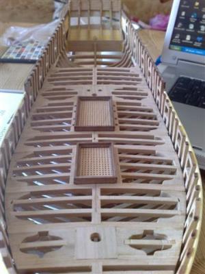
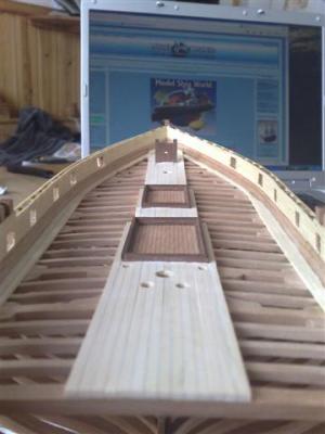
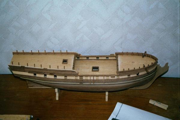
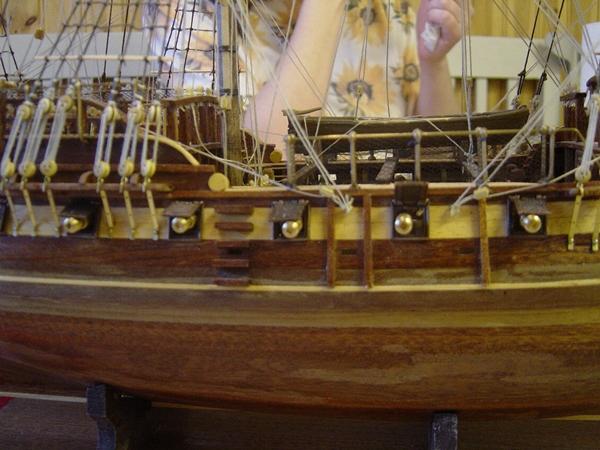
Planking with a beautiful pine and adding the deck details. I deviated a little from the manual in my planking since I wanted to conceal a few minor mistakes I made on the framework of the deck
-
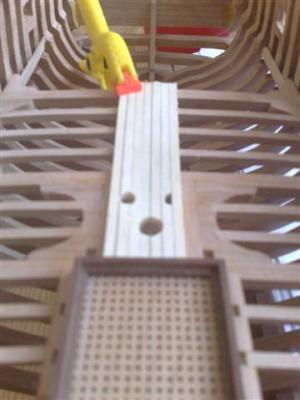
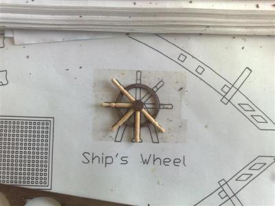
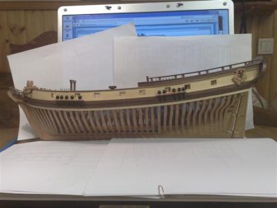
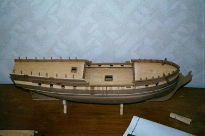
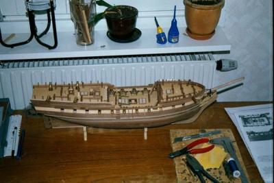
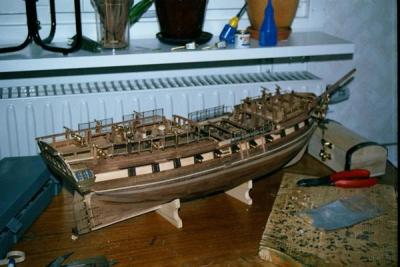
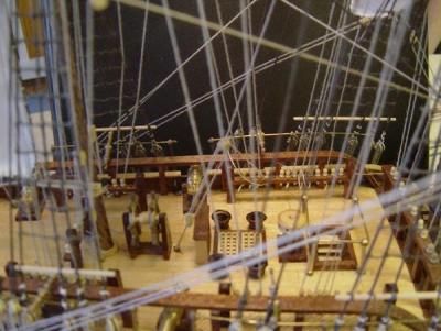
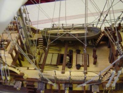
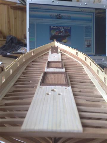
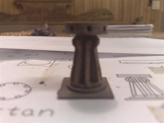
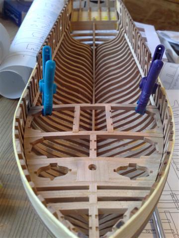
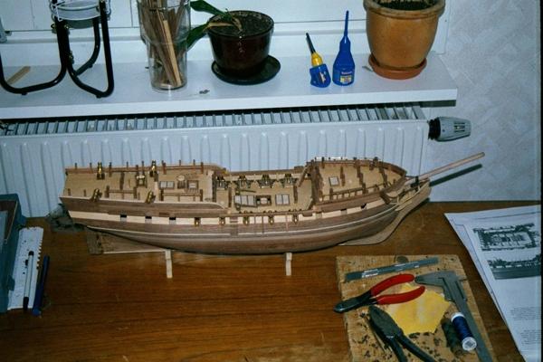
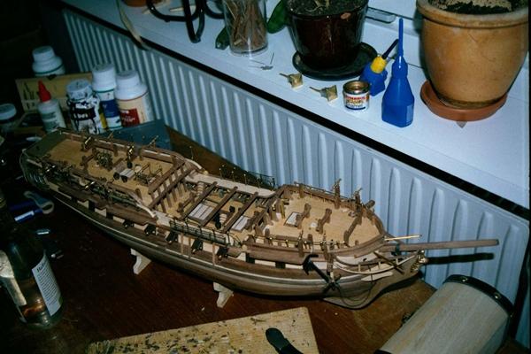
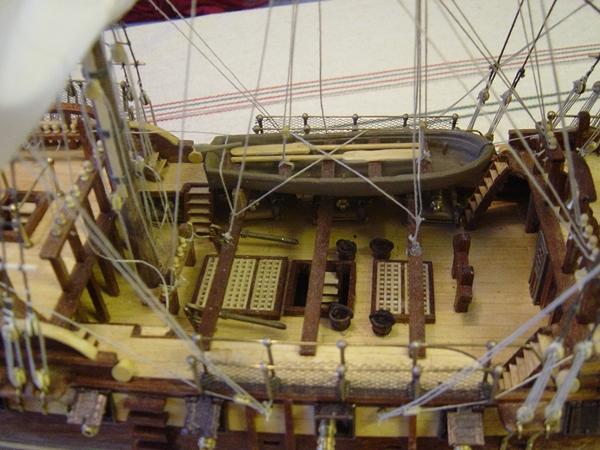
Having finished the framing of the main deck framing focus turned into creating the deck furniture such as gratings, wheel, binnacle and capstain.
-
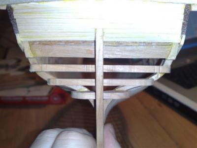
The framing of the deck is one of the most interesting parts and also beautiful parts of this kit if you ask me. The manual uses correct names for the parts such as knees, carlings and ledges instead of only referring to part this or that. This method is frequently used in the manual which I found most educational. During
this framing I realised that my hull was too slim towards the stern and therefore the parts had to be adjusted slightly at the stern part of the deck.
This underlines the importance of thoroughness in the assembly of frames and the fairing of the inside of the hull.

-
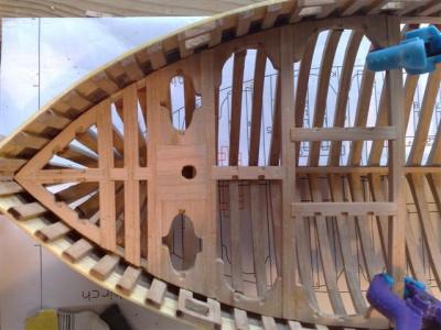
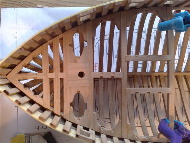
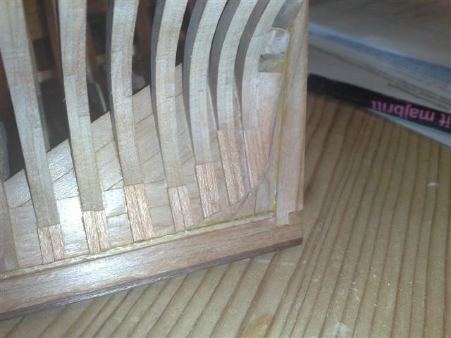
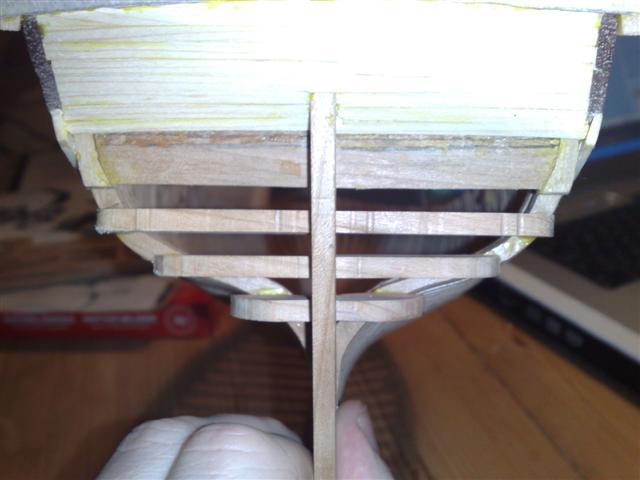
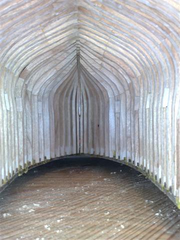
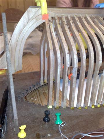
The frames at the stern would have been too slim at the end by the keel to have been milled so additional wood is needed to create the appearance of a complete frame. Shown here is also the inside of the hull faired and prepared to receive the deck framing.
Later I realized that I had not removed enough wood on the inside of the hull to get a satisfactory fit of the deck-beams of the main and quarter deck. Also the
ledges had to be adjusted.

-
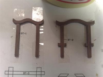
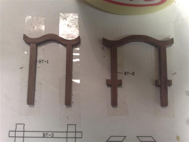
The transom timbers are one of the few parts I had to adjust a lot before I could achieve a satisfying fit.

-
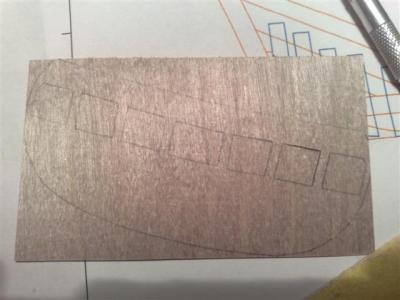
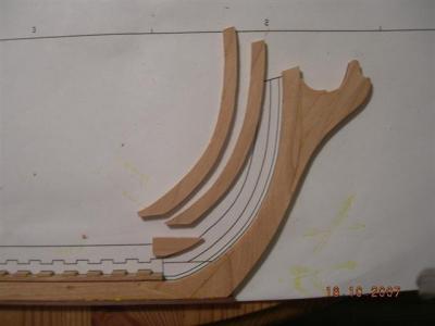
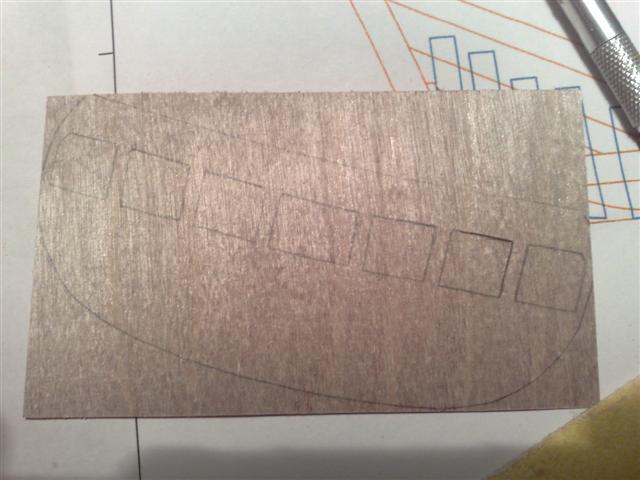
The frames had to be trimmed down to the planking and then a template was used to make the base for the stern galleries. Cutting out the windows was a bit tricky. The manual calls for using rubber cement to secure the template to the thin plywood although I had no such cement so I decided to draw the pattern directly to the wood which worked also. I think one can obtain a greater precision by following the manual though.

-
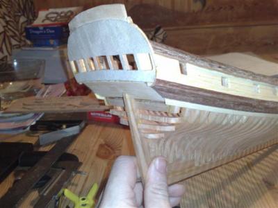
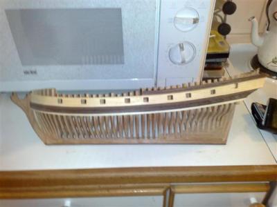
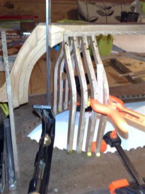
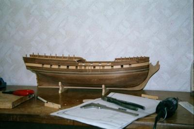
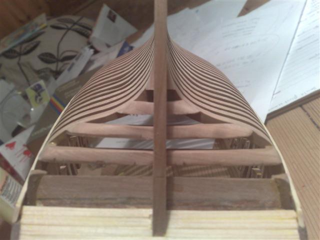
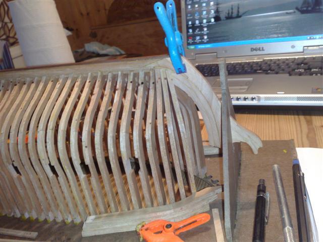
Time had come for the magical moment of cutting the model from the jig. I used a hand saw but ended up removing the handle and cutting with only the blade as I have no small cutting blade. It hurt but worked. After tossing the jig I was amazed at how light the model is.The last picture shows my failure to obtain a sufficient rabbit line, I’m not to happy with the way the whales touch the stem, this is an area that needs more attention on my next kit.
-
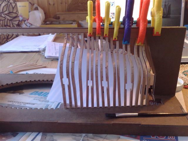
During planking I started to realise what the yellow aliphatic resin was doing to my model but the damage having been done I decided to keep going and try to be more thorough wiping exec glue of with knife and wet cloth. Gunports had to be cut out but with the sturdy gun port frames serving as a guide for the blade the square shape was easily obtained. By the stern the transom frames were glued in place, out of some unknown reason I glued them to the jig as well.
This proved to be a mistake and I had a bit of trouble removing the model without breaking the transom frames, I had to carve the support piece of the
jig to peaces but as it had served it’s purpose not much damage was made.

-
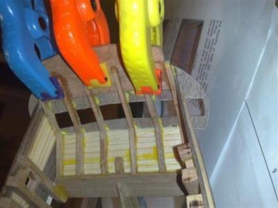
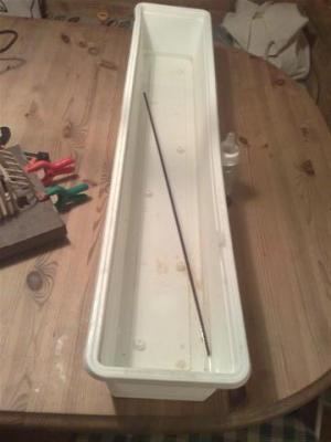
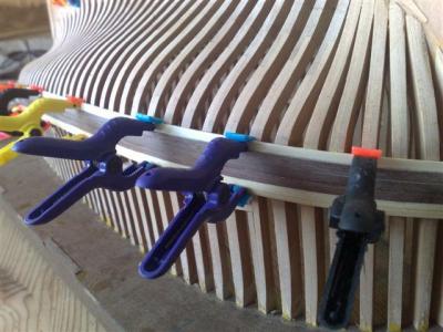
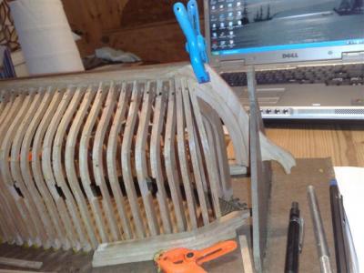
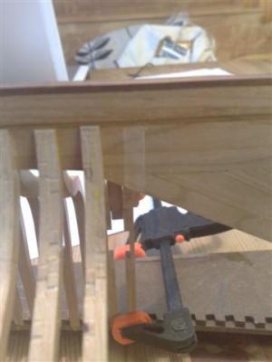
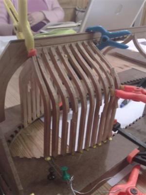
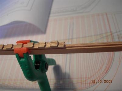
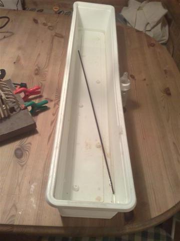
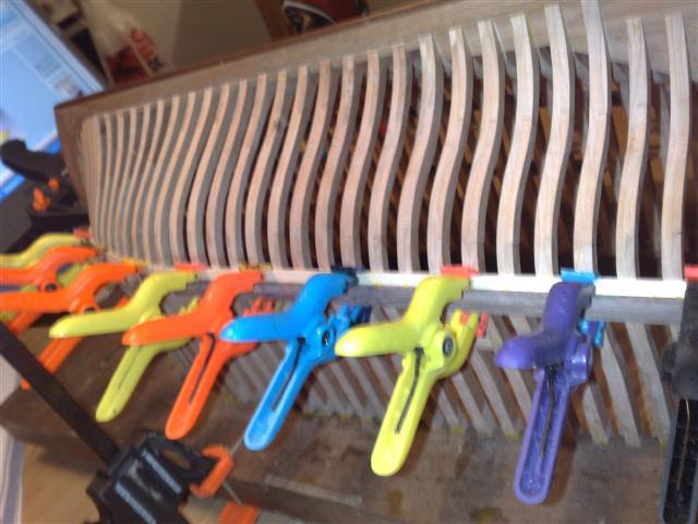
These plastic clamps started to break and jump all around the room when they snapped of. I guess there are better once out there, have a lot of them ready for use.
One pic shows my soaking device originally used for planting flowers.

-
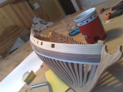
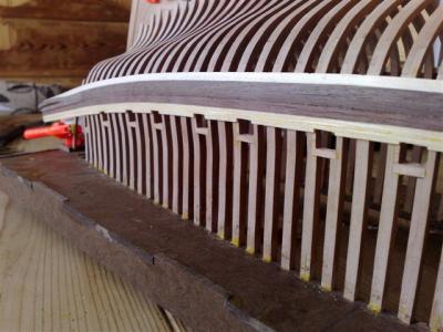
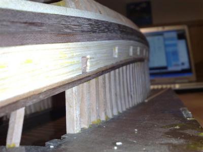
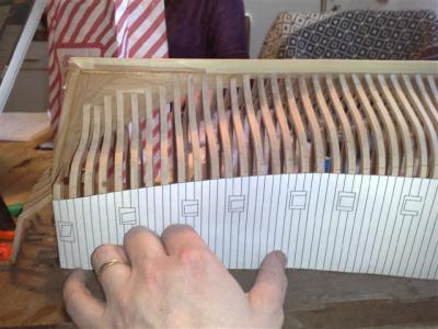
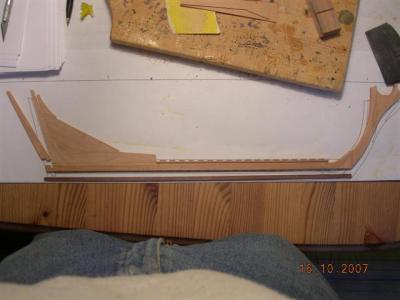
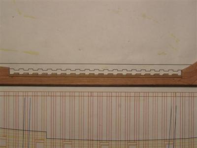
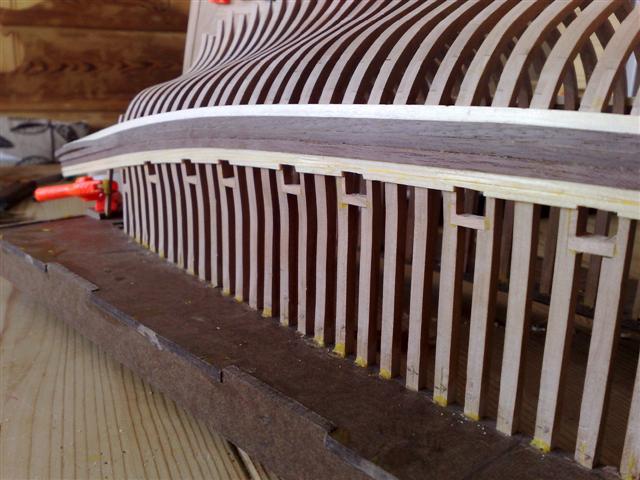
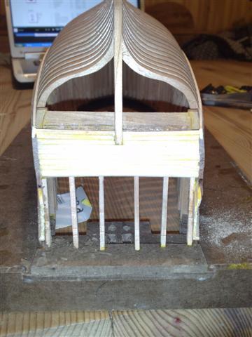
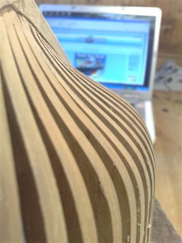
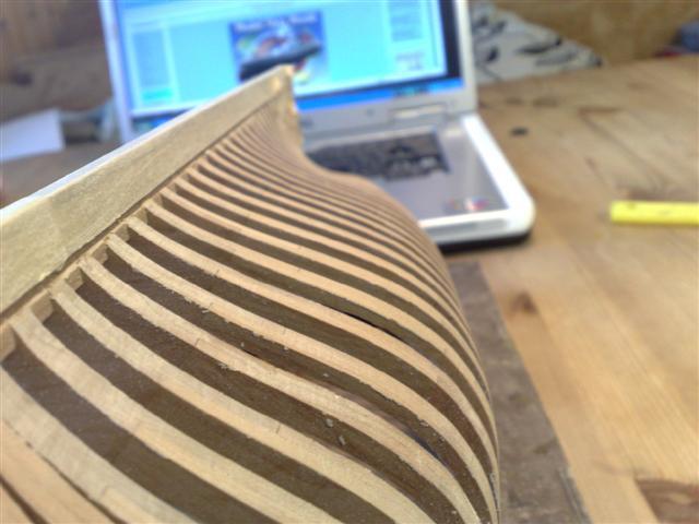
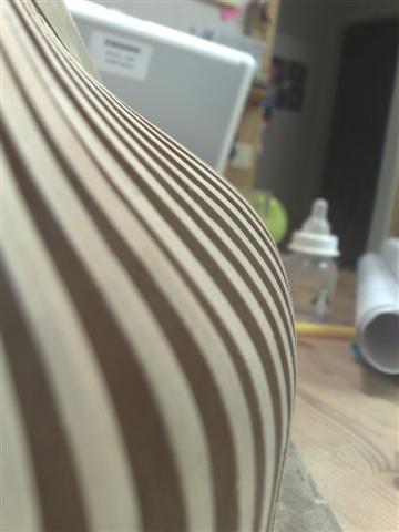
Time for planking, a template is included in the plans that I cut out to make a line along the model which forms the base for the Whales and ensures a correct
alignment. A little mind twisting to plank the hull up side down but it was not a problem.

-
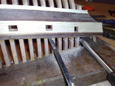
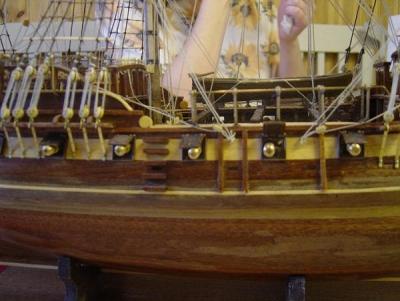
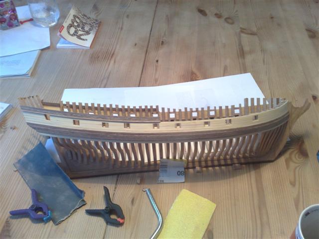
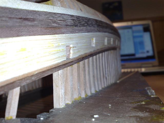
The installing of gun ports is made from CNC-port frames from a billet that are cut out, cleaned and fitted to the frames with part of them sticking out from the
hull. The exceeding part was sanded down using a dremel tool and sandpaper. Again the precision of the CNC-milling ensures a great fit more or less
directly from the billet.
The line drawn on the hull is made using a template included in the kit and shows the
lower line of the lowest whale. This is where the planking starts.

-
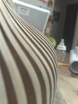
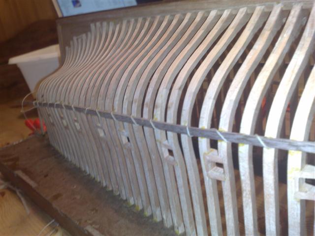
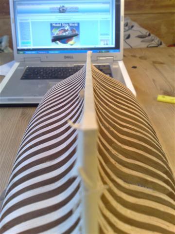
A few more pictures showing different stages of fairing. The high quality cherry that the frames are made of has a beautiful clean finish to them after fairing down to using 400grit sandpaper. I covered the keel with tape to protect it from the sandpaper used for the frames.
(Note the old MSW in the background)


-
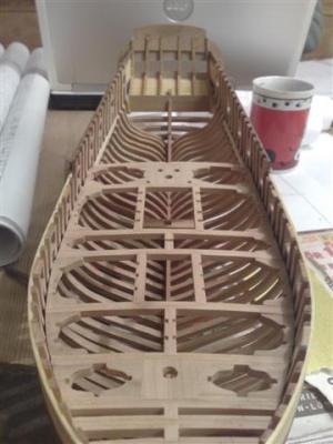
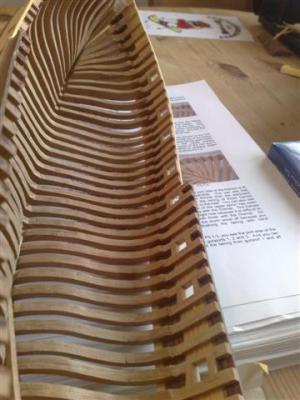
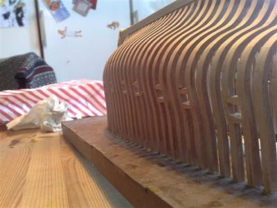
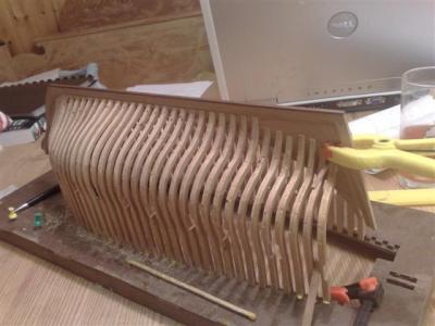
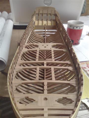
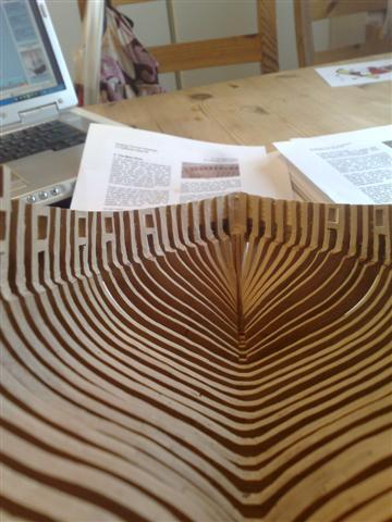
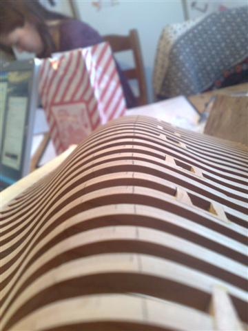
These pictures show my model fully framed. When the frames were all in place time came to fair the hull. Care had to be taken not to break any of the frames by applying to much pressure While sanding. When I build my next POF kit I will exercise more care during this part of the build especially fairing the inside of the hull which has a little rough appearance on my Fair American. The last picture shows the stem being faired.
BLFA21: A good thing to do when fairing the inside of the hull is to check the measurements of the deck beams in order to have a correctly faired hull. I failed to do so and subsequently had to adjust the deck-beams and other parts in the deck
framing quite a lot as my hull was not faired enough.BLFA22: Hull framed
BLFA23: Faired frames

-
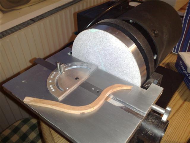
The cant frames on the stern was a bit tricky and I made a little mess of them. I had bought a Byrnes disc sander and was too eager to use it and unfortunately it ate a great deal of the frame closest to the stem deadwood making my rabbet-line a bit strange and definitely not the way it’s suppose to be. As mentioned earlier machinery is not necessary but the disc sander improved the exactness of angles and certainly made framing the model easier.
BLFA18: FramesBLFA19: Byrnes Disc Sander a great machine
BLFA20: I scraped of the varnish to ensure the glue would stick.

-
Adjusting
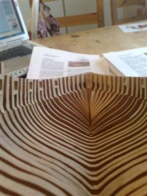
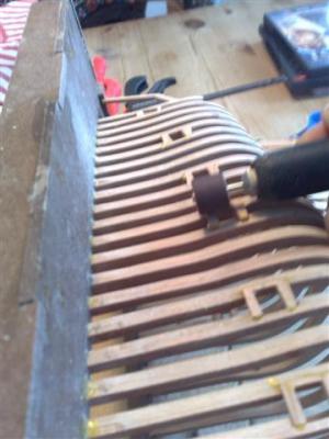
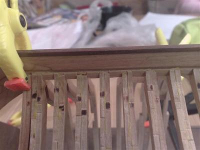
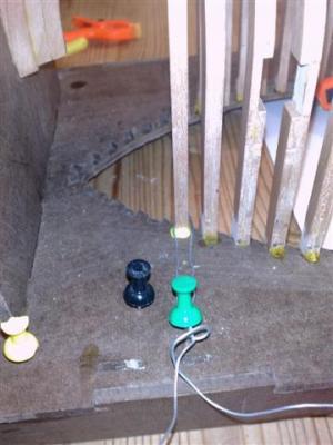
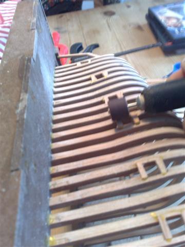
the notches in the keel and frames for a perfect fit is necessary to do before aligning the keel and gluing anything. Once this is done and the first frames are in place the next challenge is to get the frames in place without breaking them and of course assuring they are turned the right way. Once I had glued a few frames in I got the hang of fixing the frames in the right position and from then on the framing was rather simple. A few inventions were needed to secure the frames to the jig notches which is important for the final appearance of the hull.BLFA15: Eventually I used something called “wood on a tube” which is basically sawdust and glue mixed together to fix the notches that had broken.
BLFA16: A bit of inventiveness is necessary to secure the frames to the jig while the glue is setting. Securing the frames correctly to the jig is essential for the shape of the hull and fit of the deck parts.
BLFA17: Here the spacer to ensure alignment of the frames is shown.
-
Thanks Joe
But as this topic is meant as a review of a specific kit, I dont think mixing up the pictures with scratch built versions of the ship is a good idea.
I suggest that you create a topic of your own and post the pictures there as I´m sure many are interrested to see them. Make sure that Copyright wont be an issue first though.
Regards
Erik
-
After assembling all 37 frames and applying a few layers of varnish to obtain a finish I went on to assemble the framing jig. The jig was pretty straight
forward and easy to assemble. Aligning the keel to the frame was a bit scary well aware that if I got this wrong I would mess up the whole build. It took several dry fittings of the frames and studying of the picture CD and manual before I finally had the nerve to glue the first frames in place and by this securing the keel to the jig.
BLFA12: Framing jigBLFA13: Dry-fitting frames to ensure alignment.
BLFA14: Dry-fitting cant-frames. Note that some frames seem crocked, they are. I don’t know how I managed to fail in making the frames flat like this, but by using a spacer when planking I could correct them.The picture makes it look worse.
More to comeErik


-
Last steps of the keel, adding the sternpost and false keel. Also shown is one of the 37 different frames being assembled. Using the plans with some double hefting tape to secure the first layer of frame parts and gluing the second layer over them ensured a proper alignment of the frame parts. This is one of the critical points in the construction. If one is not VERY thorough and exact assembling the frames it will have severe effects to the model, the hull will have the
wrong shape with a lot of problems arising because of this. There are a few different kinds of frames in the kit, full frames and half frames with or without gun ports. The basic assembly is the same though and the plans and manual are very clear on the topic making the assembly easy. During this part I was educated as to the terminology around frames. Ex the placement and function of the futtocks and floor of the frame.
BLFA9: SternpostBLFA10: Parts placed on the plan-frame is not yet cleaned up but the once to the right are.
BLFA11: Complete full frame glued together. To save the plans I traced the lines on ordinary
paper and used double-hefting tape to secure the bottom layer securing the frame
by gluing the second layer ontop.

-
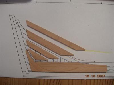
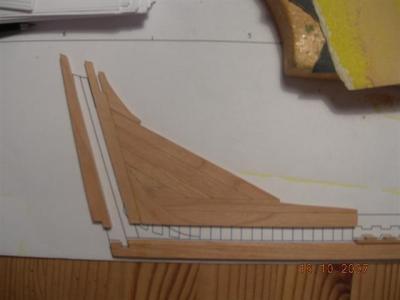
Shown here is my assembly of the sternpost and deadwood as well as gluing this to the keel completing the keel assembly. I used a yellow aliphatic resin for this kit which I today regret as I failed to remove leftovers giving the ship a slight yellow impression here and there. One lesson learned “Don’t use yellow glue on visible parts”
BLFA6: Parts for the stern deadwod
BLFA8: Keel, inner and outer sternpost visible in this picture
BLFA7: Stern deadwood and sternpost glued to the keel.
-
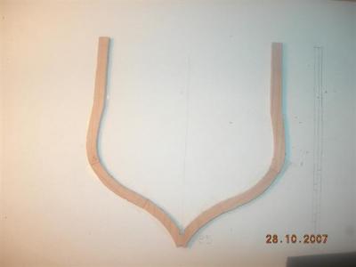
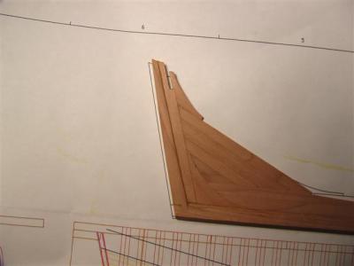
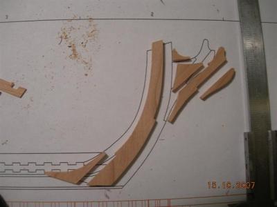
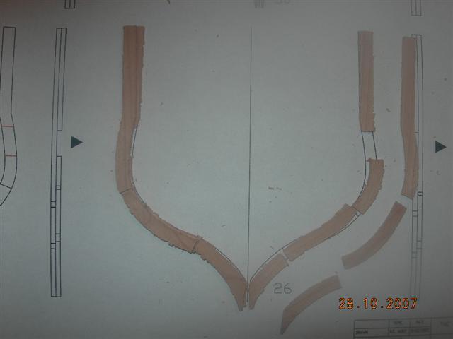
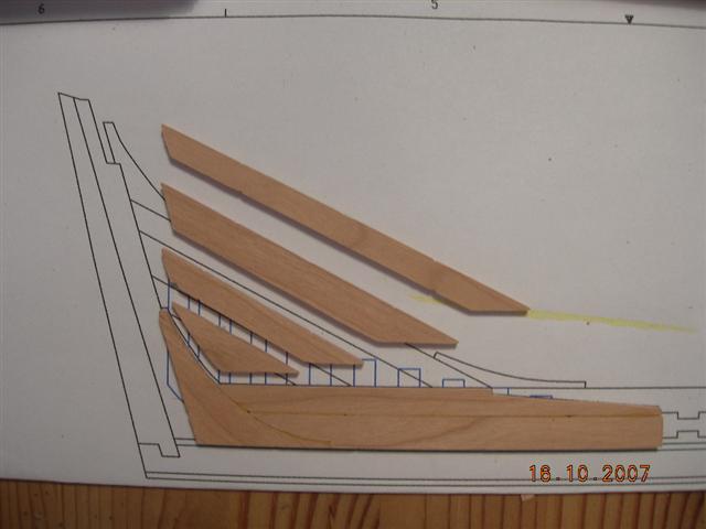
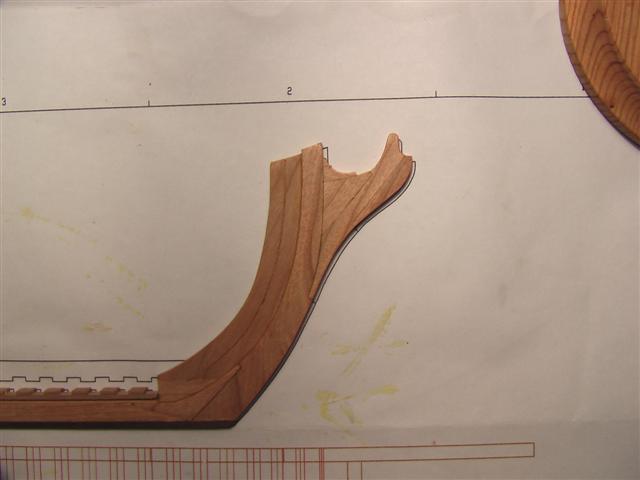
Next step the assembly of the stem, and deadwood. Working on these details I started to get an idea of the precision of the parts in this kit. The parts needed a
little cleaning from sawdust left by the milling process but having scraped this of with my hobby-knife and removed the small notch from the billet there
was an exact fit.
BLFA3: The parts of the stem and beakhead cut from their billet and cleaned upBLFA4: Note the exact fit with little or no adjustment needed
BLFA:5 Completed stem and beakhead

-
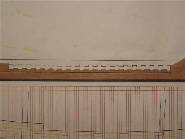
Construction starts by assembling the keel which is layered by several parts to form the notches for the frames. I had to read the manual several times to wrap my head around this but in the end it was not that complicated once I understood the basic idea. There has been an update to the kits construction after the first few kits which calls for reading the manual THOROUGHLY especially concerning the assembly of the keel.
BLFA1 :Principle of layers creating nothches. This principle is used throughout construction of the ship.
BLFA2:Notches and rabbet-line of the keel
-
BUILDING THE LAUCK STREET SHIPYARD
FAIR AMERICAN
I have no commercial interest in and no financial gain from writing this building-log / review, I’m
only a very happy customer //Erik Nyren
Reposting this buildinglog ended up somwhere between a review and a log so I leave it up to our admins to move it if necessary
Unfortunally this kit is no longer available however this buildinglog does give an idea of how to build a scratch model of the ship. Perhaps it can be of help to members building the Model Slipways Fair American kit, so I figured its worth reposting.To be honest I think the original complete log was posted on Dry Dock Models and only parts on MSW but it matters not.
Historic background
The history of the 16gun 1780 Revolutionary war Brig Fair American is not one I have been able to wrap my head around. It would seem that there have been several Fair Americans throughout history and that the Lauck Street Shipyard kit is based on plans drawn by Clayton A. Feldman. Those plans are drawn from the model of the Fair American in the Rogers collection at the Naval Museum
in Annapolis, MD.For a deeper study of the Fair American history I would recommend the booklet “Progressive Scratch-Building in Ship Modeling” By Clay A.Feldman MD which in addition is a very informative publication on the basics of scratch building a ship model as well as a complementary book on the rigging of the Fair American.
The Lauck Street Shipyard kit is a somewhat simplified POF-construction and not to be considered historically correct although this is the prise that has to be paid to have a kit of such complexity comprehensible for a lesser skilled modeller. From an amateurs point of view
(that would be me) the kit is close enough to the history so I would not know the difference if not someone were to point it out.The Fair American kit
Construction (Measurements taken from my
model and may vary depending on several factors during construction)
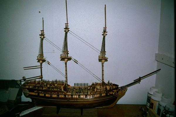
Length: ca490 mmHeight: ca157mm (stern)
With: ca140mm
The kit is a Craftsman Style kit which means that it is developed by a professional modeller and a true craftsman. Further on the term Craftsman style stands for the highest quality and that the precision of the parts is a lot better than your general kit. What is a bit unique about this kit is that it’s a true plank on frame construction kit whereas most kits on the market are solid hull or plank on bulkhead.
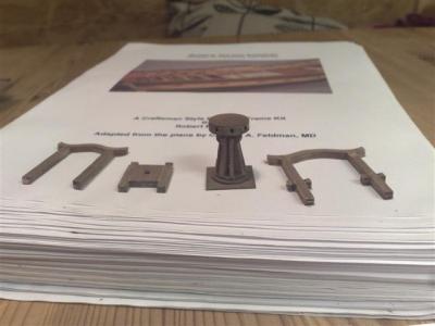
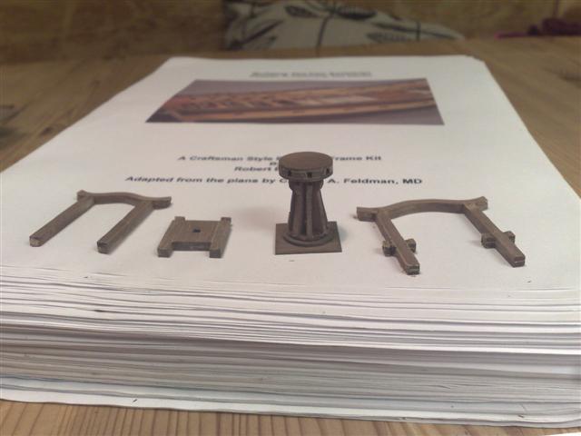
The kit comes with a number of wood billets with CNC-milled parts and the strip wood organised in labelled bags, there’s also some very nice photo etched parts and some other small parts for the deck details. There are 11 sheets of plans included covering all frames, profile view and templates for rails and gun ports among other things. There are also two additional sheets included covering the standing and running rig although the kit does not include materials for building the rig.
The Fair American is a partially planked, true plank on frame (POF) construction exposing the inner construction of the ship to the viewer. The frames and many other parts are built up by gluing layers of CNC-milled parts resulting in a very sturdy and robust construction.
Included in the kit is a Han style jig for framing the model in an up side down position.Materials
The wood is of the highest quality American hardwood such as cherry, walnut, aspen and pine which calls for great contrasts in colour. I had no problems with strip wood breaking whilst bending or strips being milled unevenly. Some small parts have a tendency to break when cut from the billet due to their small size and thin billet, this is not a problem though as the kit includes ample security for this by including enough spares to these parts so breaking a few does not matter. On a few occasions I broke too many with my thick fingers, this was
solved by drawing up the part on the same billet and recreating it.Manual
Now here’s a treat. The manual actually comes in the form of a CD in order to cut costs, which is commendable. It can be printed out if one prefers to have it lying around. The manual is very pedagogical taking you through the build step by step with strategic pictures in colour to show critical points of construction. Mr Hunt has obviously gone into a great deal of thought when writing the manual
which is more of a practicum than a dry manual. It is written with care in a personal and delightful manner. The manual includes tips and tricks as in what to do and potential areas where mistakes can be made. There are three
additional CD:s included with pictures of the different stages of construction.
PlansPlans are stored rolled up in a hard-paper tube eliminating folds that can mess up measurements. The plans are very good and clear with thin lines making measurements easy. Many of the sheets are multicoloured illustrating the construction in a pedagogical manner.
The precision of the plans enables you to check your parts directly on the plan which you are repeatedly asked to do in the manual especially whilst assembling the frames.
Building experience
Building the Fair American kit is most rewarding, as the kit holds a quality that I have never seen. I have been able to learn unbelievable much in a short while as I could concentrate on the POF-construction and learning the basics of a ships
construction in stead of spending hours compensating for badly designed parts.The personal customer service provided by Mr Hunt can not be compared with the larger manufacturers where responses are scarce and often the employees handling support has never built the kit in question. The fast and friendly responses from Mr Hunt adds to the building experience.
SummaryThe Fair American is a kit that I strongly recommend to anyone wanting to learn the basics of POF modelling but also the more experienced builder would have a wonderful time building her. The kits outstanding quality in wood, plans and
manual makes sure you can build a beautiful model with limited or no prior experience of POF models and no expensive machinery. This fine kit and with the service and support from Lauck Street Shipyard from the purchase throughout the
build to a finished model gave me an overall building experience yet to be surpassed, and this for a most reasonable prize.
Building experienceBuilding the Fair American kit is most rewarding, as the kit holds a quality that I have never seen. I have been able to learn unbelievable much in a short while as I could concentrate on the POF-construction and learning the basics of a ships construction in stead of spending hours compensating for badly designed parts.
The personal customer service provided by Mr Hunt can not be compared with the larger manufacturers where responses are scarce and often the employees handling support has never built the kit in question. The fast and friendly responses from Mr Hunt adds to the building experience.
SummaryThe Fair American is a kit that I strongly recommend to anyone wanting to learn the basics of POF modelling but also the more experienced builder would have a wonderful time building her. The kits outstanding quality in wood, plans andmanual makes sure you can build a beautiful model with limited or no prior experience of POF models and no expensive machinery. This fine kit and with the
service and support from Lauck Street Shipyard from the purchase throughout the build to a finished model gave me an overall building experience yet to be surpassed, and this for a most reasonable prize.
MaterialsThe wood is of the highest quality American hardwood such as cherry, walnut, aspen and pine which calls for great contrasts in colour. I had no problems with strip wood breaking whilst bending or strips being milled unevenly. Some small parts have a tendency to break when cut from the billet due to their small size and thin billet, this is not a problem though as the kit includes ample security for this by including enough spares to these parts so breaking a few does not matter. On a few occasions I broke too many with my thick fingers, this was
solved by drawing up the part on the same billet and recreating it.
ManualNow here’s a treat. The manual actually comes in the form of a CD in order to cut costs, which is commendable. It can be printed out if one prefers to have it lying around. The manual is very pedagogical taking you through the build step by step with strategic pictures in colour to show critical points of construction. Mr Hunt has obviously gone into a great deal of thought when writing the manual
which is more of a practicum than a dry manual. It is written with care in a personal and delightful manner. The manual includes tips and tricks as in what to do and potential areas where mistakes can be made. There are three
additional CD:s included with pictures of the different stages of construction.
PlansPlans are stored rolled up in a hard-paper tube eliminating folds that can mess up measurements. The plans are very good and clear with thin lines making measurements easy. Many of the sheets are multicoloured illustrating the construction in a pedagogical
manner. The precision of the plans enables you to check your parts directly on the plan which you are repeatedly asked to do in the manual especially whilst assembling the frames.
More to comeRegards Erik
-
-
More pictures from my HMS Pandora


Fair American by Erik Nyren - FINISHED - LSS - POF (kit discontinued)
in - Kit build logs for subjects built from 1751 - 1800
Posted
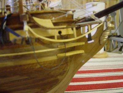
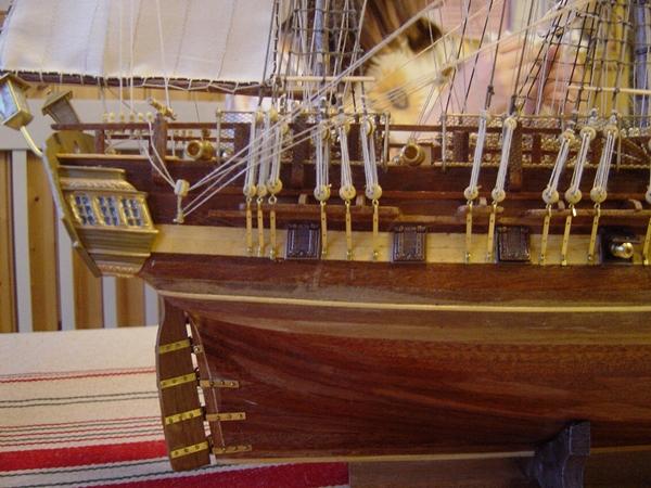
Preparing and assembling the headrail unfortunately exposed more of my hull not having the correct form. Alas when working with wood you adjust and adapt. The result, the headrail is not protruding evenly throughout the hull but I can live with that.