Supplies of the Ship Modeler's Handbook are running out. Get your copy NOW before they are gone! Click on photo to order.
×


Hank
-
Posts
632 -
Joined
-
Last visited
Content Type
Profiles
Forums
Gallery
Events
Everything posted by Hank
-
 Kevin, To be truthful, it hasn't actually been discussed in several months. HOWEVER - it is on my BB Bucket List and time allotted, could happen one of these days! I've got a summer of med. procedures being scheduled (brain transplant, etc. - nothing dire, just need to be done) so this COULD be a fall or next spring type event - or ....later. Being in the active work force, I simply can't plan things too far in advance. The Admiral....you all understand - but, I'll keep you in mind. These sort of things DO happen from time to time, just takes planning (and $$!). Hank
- 187 replies
-
- 4
-

-
- new jersey
- trumpeter
- (and 2 more)
-
Kevin, Thanks for the support! The hull is 1/2 way there - I still have the stbd. side to grind down to shape. Once that's done, I can establish the waterlines, bootopping, and start work on horizontal hull plate layout - this will be a bitch since these curvatures are guesstimates. A few of us have talked about a trip to Norfolk to take a survey by boat and record measurements of the actual ship's plate lines. It's still up in the air. Later, Hank
- 187 replies
-
- 6
-
-
- new jersey
- trumpeter
- (and 2 more)
-
Yea, I've seen it. Entertaining, but hardly realistic. I did like some of the various interior shots of MO. Special Effects were really neat!
- 187 replies
-
- 4
-
-
- new jersey
- trumpeter
- (and 2 more)
-
O.C., Thanks for the kind remarks. At this point, with (sort of) 2 models in progress, it's hard to stay fixed on completion of one when there is interest in both. Perseverance, I hope will rule the day. Hank
- 187 replies
-
- 4
-
-
- new jersey
- trumpeter
- (and 2 more)
-
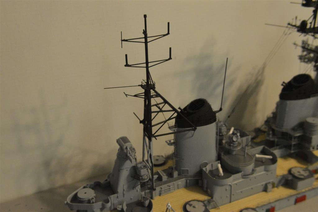
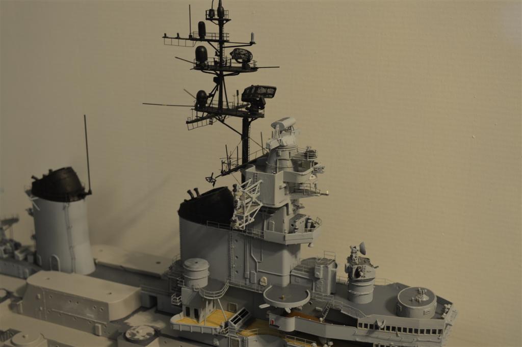
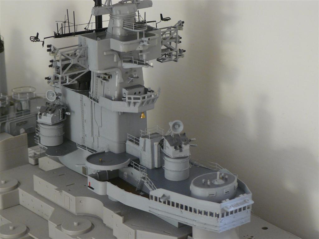
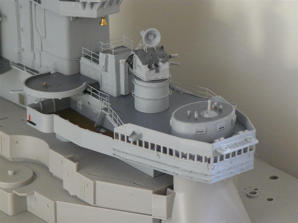
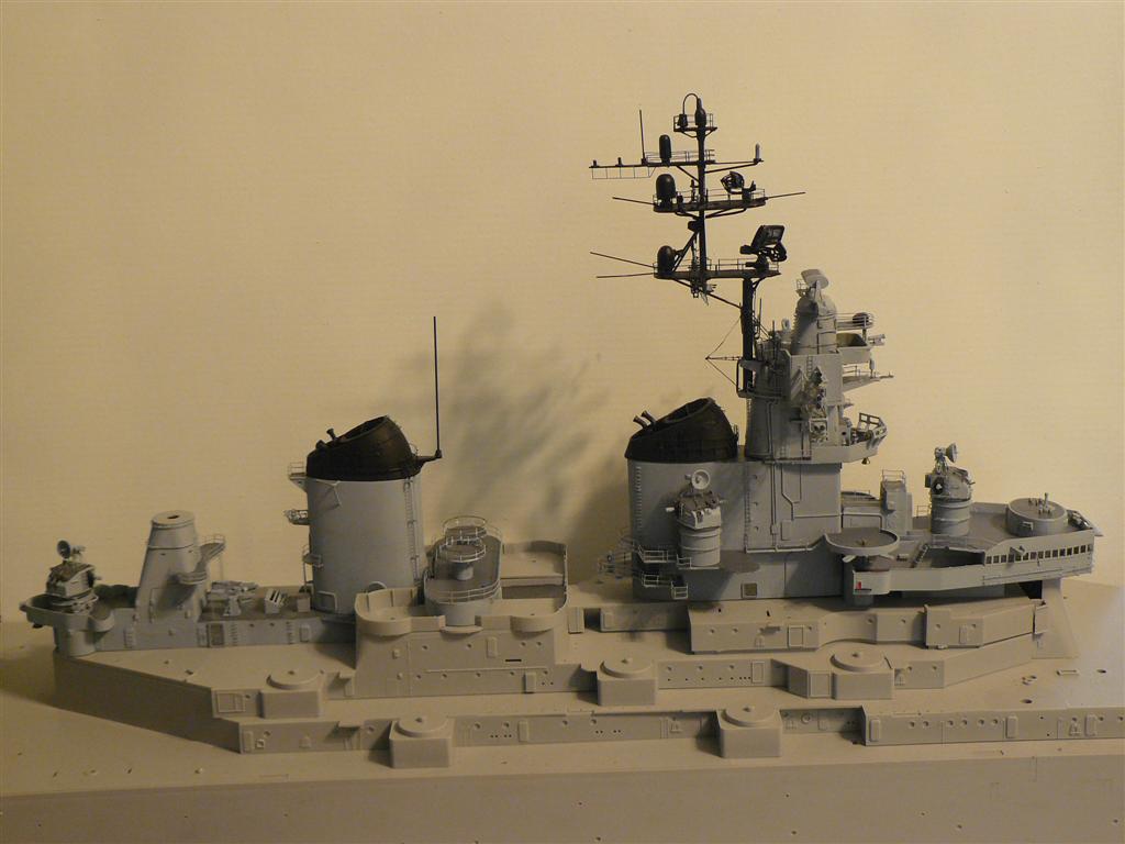
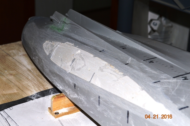
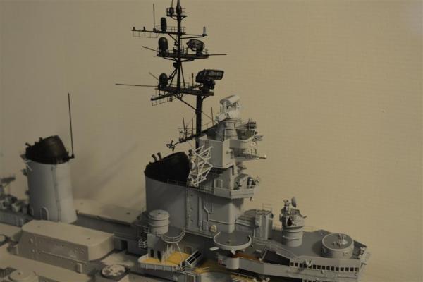
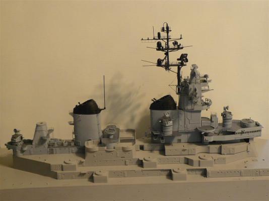
Well, it's been a while since I updated this build. I've made quite a bit of progress - the superstructure is now for all intents and purposes completed. With the exception of the whip antennas, which will be added at the appropriate time, I'm now concentrating on hull work. In addition, I've started slowely construction of a kit bash to produce an early 1940's (pre-war) USS PENNSYLVANIA (BB-38) using the Trumpeter 1:200 scale ARIZONA kit as the basis. To continue with this build: The kit hull is a disaster - both forward lower hull and after lower hull are misshaped from the git-go. So, a year or more ago I tackled the forward end adding styrene strips/putty as necessary to achieve a close resemblance to the proper shape. This is shown in the following photos. I have recently begun grinding work on the after hull to reduce down the incorrect shape to it's proper appearance. I am half way done with this having the basic shaping completed on the port side. I will continue the stbd side in June. For a while it looked like another modeler's 3D Modeling design might be a possibility as a replacement for the after 19" of the kit hull. This was not to be, so I came up with a less high tech, but fairly accurate method for hull shaping on my own. While another modeler did a POB replacement for offending areas of the after hull, I am taking a different approach and FILLING the hull interior with Bondo, allowing it to dry completely, then grinding the exterior down to shape using templates at the various hull stations according to the original ship's drawings. The photos (in no order) - completed superstructure showing 5" gun mounts, lower after area modified, lower bow area modified, and another shot of the port side superstructure. My photos are small shots of specific areas, I don't have an overall superstructure on my flash drive. Credits to other's involved, etc: The Mk. 37 and Mk. 56 FC Directors were products of Model_Monkey, 3D printed by Shapeways and available online in his store. He is a friend, fellow vet (USA) and modeler, and we are in cahoots on several other items for ship modelers - I helped his design of the Mk. 56 director. The 5"/38 dual gun mounts are also his products as the kit mounts are incorrect for this class of BB. The ship's ribbon board was a reduced size rendering for me by Mike Gaughan (Cliffy_B on SMF) of Virginia Beach who has a photo program to take and reduce photos to miniatures, retaining all the proper sizes and colors. He is also a volunteer on USS WISCONSIN in Norfolk, VA. So, here are a few shots of the model:

- 187 replies
-
- 15
-
-
- new jersey
- trumpeter
- (and 2 more)
-
Mark, Thanks for the kind remarks! There is a group of IOWA class battleship nuts who are all building either a 1:200 or 1:192 scale model of the various (4) ships in one or another of their configurations. As things progress, it appears more and more that constant detailed research is ongoing since the "one size fits all" does NOT apply in this case. And, as many of the modelers are building this kit (or its sister kit IOWA) in the out of the box configuration (end of WWII) even that is becoming hard to accomplish due to problems with the kit itself. So, it's quite an interesting project going on throughout the country right now. Add to that the guys that are getting into the 1:96 scale R/C models that are on the extreme end of things...I won't go there!! Hank
- 187 replies
-
- 4
-
-
- new jersey
- trumpeter
- (and 2 more)
-
Elia, Yes, I have drawn up all the life raft racks in CAD (MicroStation) and will print out the file using the MicroMark PE kit they currently sell (I bought it about a year ago). They give you enough materials to print out 2 half sheets or 1 81/2 x 11 (I think???). I already have molded the life rafts using their 2 part plastic molding system. I may also mold the Mk. 56 directors but need to create a 3D solid model of that and that may take a while to either do myself of find someone to draw it up for me. I'd rather do it myself, but the software is rather pricey and then there's the learning curve! David B - I think 1/72 is a bit large - 1/8" (1:96) seems to be a much more useable scale. Hank
- 187 replies
-
- 1
-
-
- new jersey
- trumpeter
- (and 2 more)
-
David & Popeye - Thanks for the nice comments. Long term projects are just that!!
- 187 replies
-
- 1
-
-
- new jersey
- trumpeter
- (and 2 more)
-
Thanks, OC! Much appreciated!
-
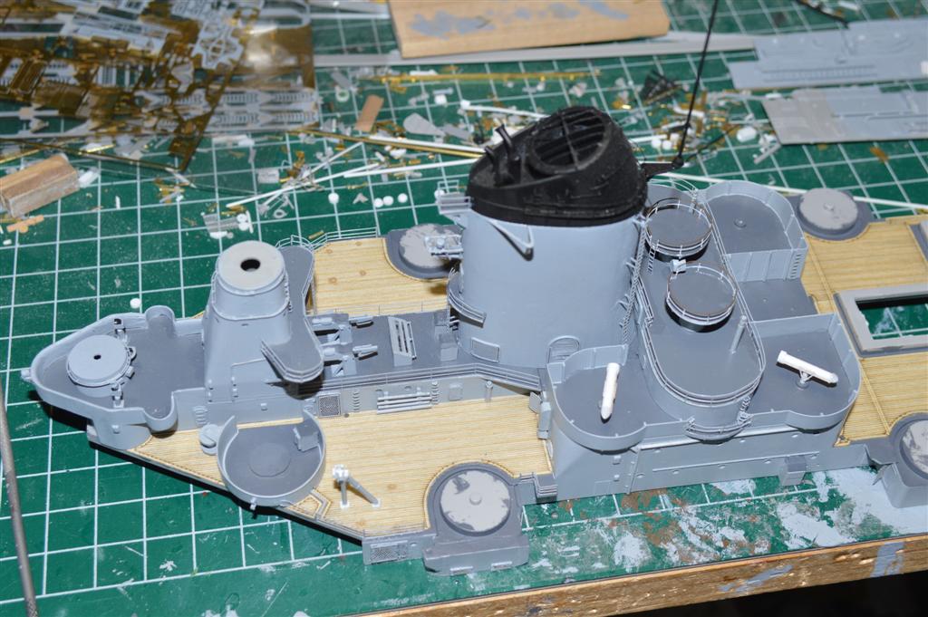
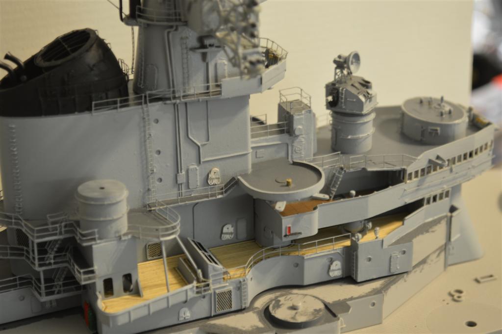
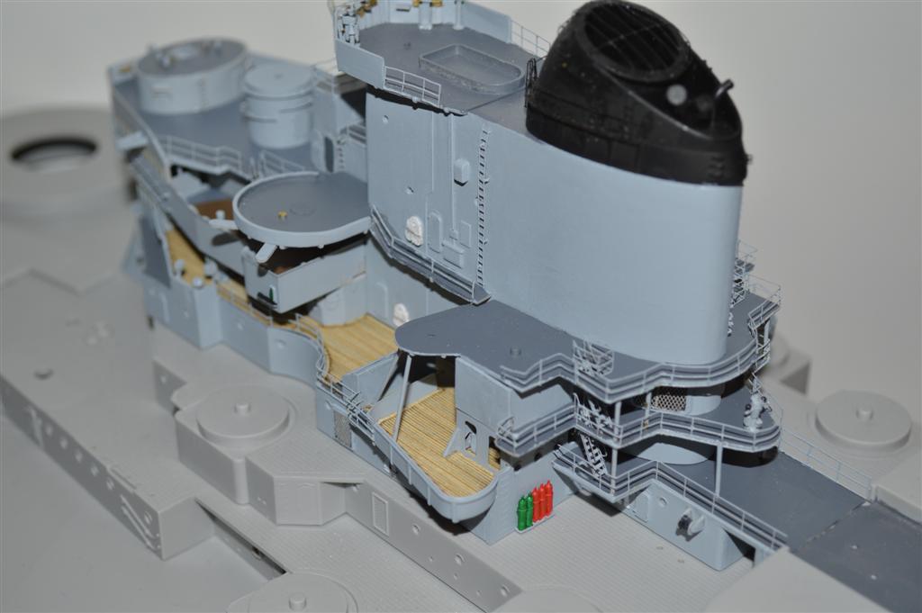
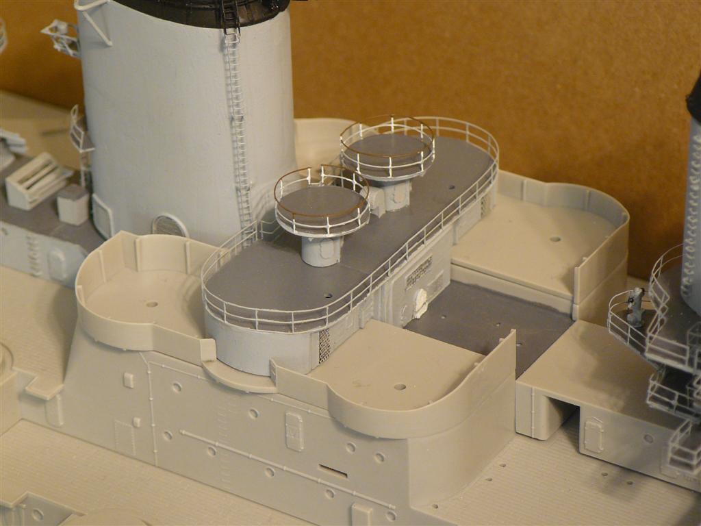
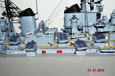
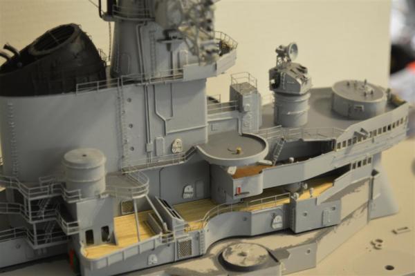
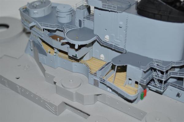
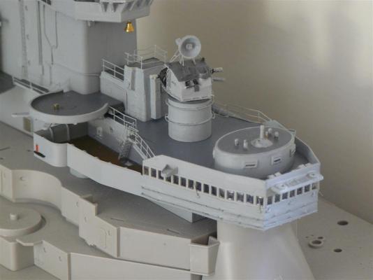
Well, here are some photos of the After 02 Level/Midships 02 Level superstructure that I've been working on lately. Since I AGAIN can't see the attachment info in the edit box, I'll make my comments here rather than after the photos due to the reason just stated - I have no way of telling where the photos end to continue my comments. This area of the superstructure is modified from the kit in that NEW JERSEY had her center (6) 40mm mounts removed and replaced with (4) Zuni Chaff Rocket Launchers and a Mk. 56 Fire Control Director platform in the center tub area. The Mk. 56 Directors were added in the mid-50s but were relocated on this central athwartship platform in her 67-68 refit. The Mk. 56 FC Directors will be scratchbuilt at a later time, as will the various life raft racks that were located throughout the superstructure. I have these drawn up in CAD but haven't created the brass PE sheets that they will come from. The after 40mm tubs were refitted with Ready Service Lockers and a hose/cable reel just to the after wall of each tub. The center photo shows the refueling/high line transfer tripod also added during this time period. As well, various equipment along the bulkheads have been added/modified for this configuration. One of the other modelers on another forum to which I also post this build has mentioned a problem with the deck level around the (3) 5" gun mount bases. I will research that prior to continuing any other work on the 02 Level so that if this also needs to be rectified it can be done before anything gets put in the way of those open areas. This issue will also possibly affect the 01 Level 5" mounts (2). I hope to do further work by adding the forward superstructure unit next week to this assembly and then move on to the 01 Level which will also require various modifications. I have also done work on the lower bow to bring it closer to the actual "bulb" that was not present in the kit hull. As I've mentioned before, the kit hull "sucks" - it simply isn't correct and will take further work to correct the after 20" or so which is not shaped properly. Various methods/schemes/modifications are under investigation so nothing has been decided upon at this time. It will NOT remain out of the box I can assure everyone of that!


- 187 replies
-
- 12
-
-
- new jersey
- trumpeter
- (and 2 more)
-
David B wrote: David, Well, your friend is only partially correct, the IOWAs were retired first, due to the operational cost at the time, and secondly, (and this is my opinion here) due to the IOWA Turret 2 Explosion in 1989 from which the Navy never fully recovered it's support for the ships (PR - and they have only themselves to blame for that). Their superstructure construction (which includes the 17" thick armored conning barbette) has very little to do with their combat survivability. In the 1990s munitions were changing, but when you consider that the IOWAs were built to withstand 16" armor piercing projectiles and keep fighting, the missiles in use would not have had the power to knock those ships out of action - and the Russians very well knew this (well, the Soviets, at the time) and steered clear of them. IMHO, our ships today look more like cry-babies than actual menacing warships - we are NOT on the right track with our warship development. Hank
- 187 replies
-
- 1
-
-
- new jersey
- trumpeter
- (and 2 more)
-
David B - Thanks so much for the remarks!! The research is a necessity for building this era ship - there IS info out there and some people who know things - finding it is the key. Elia - Appreciate the reply! The antenna structure is the 2nd - the 1st was close, but no cigar!! Once again, another source of info (in this case someone who worked on NJ in the '67-68 refit) was able to steer me in the right direction. Of course, today's NEW JERSEY has been radically modernized from what my model is representing and I agree - I think the older version was a bit more impressive overall (biased opinion, of course!) Hank
- 187 replies
-
- 2
-
-
- new jersey
- trumpeter
- (and 2 more)
-
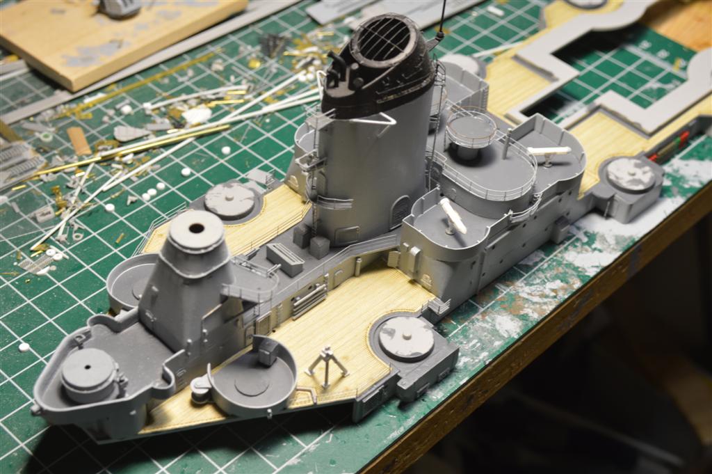
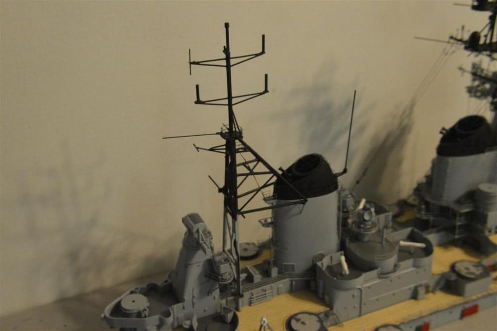
This week's work: I've now got the conning tower assembly mated to the bridge assembly (03/04/05 Levels) and am currently working on the 02 Level superstructure assembly (modifying as necessary, adding PE parts, vents, ladders, etc) and will finish with the wood decking. Scrutinized by fellow IOWA Class modelers on The Ship Model Forum (LOTS of Battleship nuts over there , as well as bonafide BB volunteers on board the WISCONSIN/IOWA museums) I will need to check on a couple vert. ladders that may need modifying on the 03/04 Level Nav. bridge. Here are a couple shots of the work: I would add more, but I can't see where the photos location is in the edit box (is something screwed up here?) so I don't know where any further commentary will end up.
- 187 replies
-
- 14
-
-
- new jersey
- trumpeter
- (and 2 more)
-
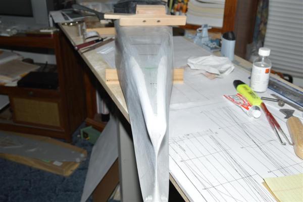
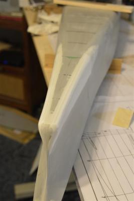
Update on build: I've now got most of the 03/04/05 Levels on the superstructure (fwd) complete and assembled. Next week the addition of the conning tower will complete the main structure. Paint, railing touchups and addition of whip antennae will get this part of the build well in hand: I will then turn my attention to the lower fwd. hull corrections - I've got styrene strips in place with white putty to enlarge the "bulb" at the fwd. extreme bow and hope to correct the misshaped kit hull

- 187 replies
-
- 16
-
-
- new jersey
- trumpeter
- (and 2 more)
-
Thanks, Kevin - much appreciate it! I don't know about the current 1:200 scale hulls from Trumpy, but the IOWA kit hulls seem to be identical (with flaws) to the MISSOURI hulls. They really need to retool their molds - they simply are not correct.
- 187 replies
-
- 1
-
-
- new jersey
- trumpeter
- (and 2 more)
-
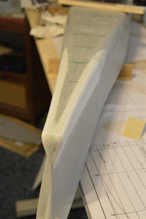
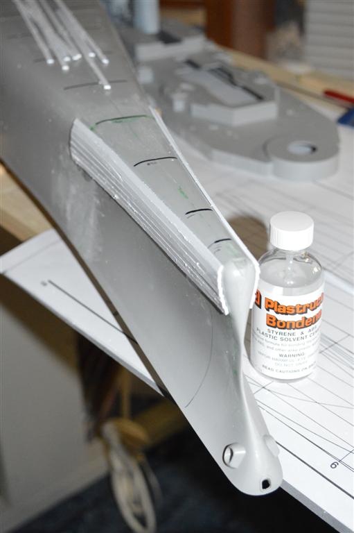
I got started with the bow area modifications last night. I had a starter pack of various Plastistrut samples and taking the 8”x3 ½”x 1/16” thk piece of styrene, I ripped it into 1/8” wide strips on my Jim Saw. Using Plastistrut Bondene Styrene & ABS Plastic Solvent Cement, I began gluing strips to either side of the bow from the flat keel downward, not covering the actual bottom of the hull since it does not need to be altered in depth. Unfortunately, this sample pack has only 1 sheet of each size of their pre-cut parts, so the next sheet (3/64” thk.) will be used for further additions once the strips of 1/16” thk. Have been used up. I check with the station template after each additional strip has been added to ensure that I’m not exceeding the max. width of the hull at that point. Before adding the next LAYER of strips, I will sand down the first layer to get rid of any debris that was left over from the ripping process. This weekend I ordered 2 tubes of Squadron Products White Putty and that should be in this coming weekend. I wanted to stay with one color on this project and since some of the orig. green putty will be hidden by this modification, I am going to use the white from here on throughout the build. I also sprayed the Pontos decking with Floquil Flat Spray Finish #130015 and have set it aside to dry. I may spray one further very light coat of finish tomorrow night and that will conclude the deck finishing and it will be ready for installation, as needed. Lastly, my close-up lens came in, so this picture was taken with the Vivatar 2x close up lens in addition to the std. 55mm lens that came with the camera.

- 187 replies
-
- 9
-
-
- new jersey
- trumpeter
- (and 2 more)
-
Frollicky One - Yea, still croakin'! Elia - I'm not sure about the etching. The artwork is CAD, but how it's printed is a mystery at this point. Thanks for the kind remarks! Hank
-
DavidB - I do appreciate the comments. I had not considered another plastic kit, but this was like a magnet!! Hank
-
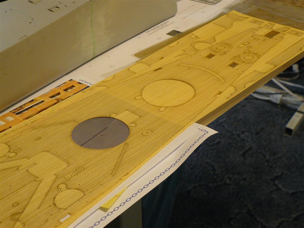
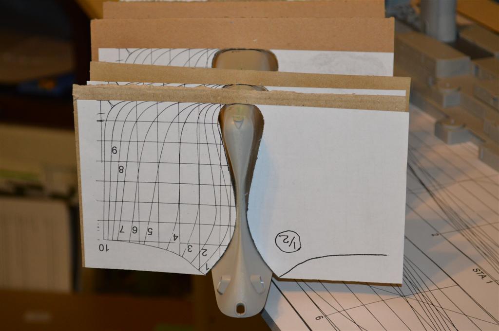
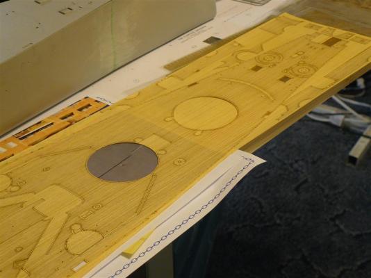
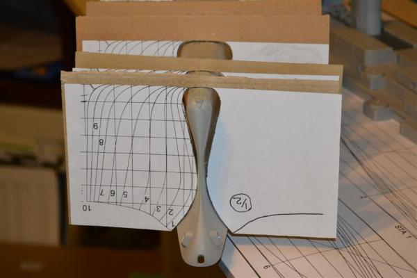
Latest work - on two fronts - Decking and Hull modifications: 1) I finally got my special order decking from Pontos just before Xmas - 5 weeks in transit from ROK. They did a fine job on it - a bit yellow in color, but it will work. I'm going to use a spray poly finish on it and that's all. I had originally considered staining, but have ruled that out. Here is a shot of the fwd deck section: 2) Fwd Hull Modifications - I'm going to do this by manual method in order to get the lower bow area modified correctly. Here is a shot of the station templates on the hull (mtd in stands and secured to the work surface) before any work is started. They don't fit correctly due to the thickness of the ext. hull needing to be shaved down: That's it for now. Hank
- 187 replies
-
- 12
-
-
- new jersey
- trumpeter
- (and 2 more)
-
Steve, Spaceman, Jimz - thanks, so much! I do appreciate the comments. Hank
-
Update as of 12-04-14: I've been working on the 04/05 Navigation Bridge and with the exception of Pelorus's, other small deck items, and whip antennae, it's complete. As usual, these pix show the superstructure together when in reality they are sitting in place only. I chose the kit bridge over the Pontos PE bridge as it was easier to work with at this point. Had I thought about it, I would have enlarged the window openings slightly in both directions as these are just a tad bit undersized. One of the Volunteers in WISCONSIN (Norfolk) made dimensioned posts regarding this earlier in the year. However, with a family situation finally coming to a close, my thoughts have sometimes been elsewhere... In any event, I have been critiqued by another battleship acquaintance who is associated now with IOWA (LA Ports) and mentioned to me a couple things that need adjustment on the 08 Level - I will handle this when I am back at my shop in early January '15. Thru the 42 years of his work at LBNSYD, he has, at one time or another, worked on all the IOWA class ships in addition to many others that came thru the shipyard. His knowledge is impeccable. I am STILL waiting on my special order Pontos Deck set and replacement PE parts (3 weeks now - nothing!) so, until it arrives, I'm unable to go too much further on superstructure work. I may begin basic hull work but that is predicated on one of the other Calif. modelers who is working on a hull replacement module (3D printed in ABS plastic) to replace the mis-sharpened after 1/3 of the kit hull. He's getting close and it's phenomenal what he's done using Solidworks and 3D professional printing. 8 bells and time to bug out. Hank
- 187 replies
-
- 19
-
-
- new jersey
- trumpeter
- (and 2 more)
-
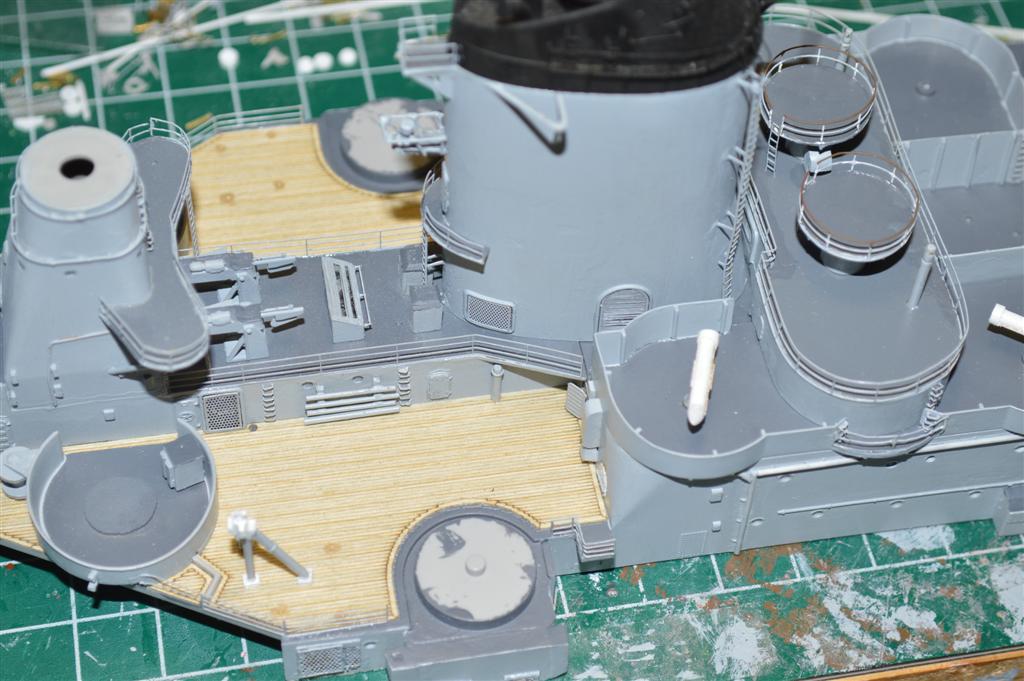
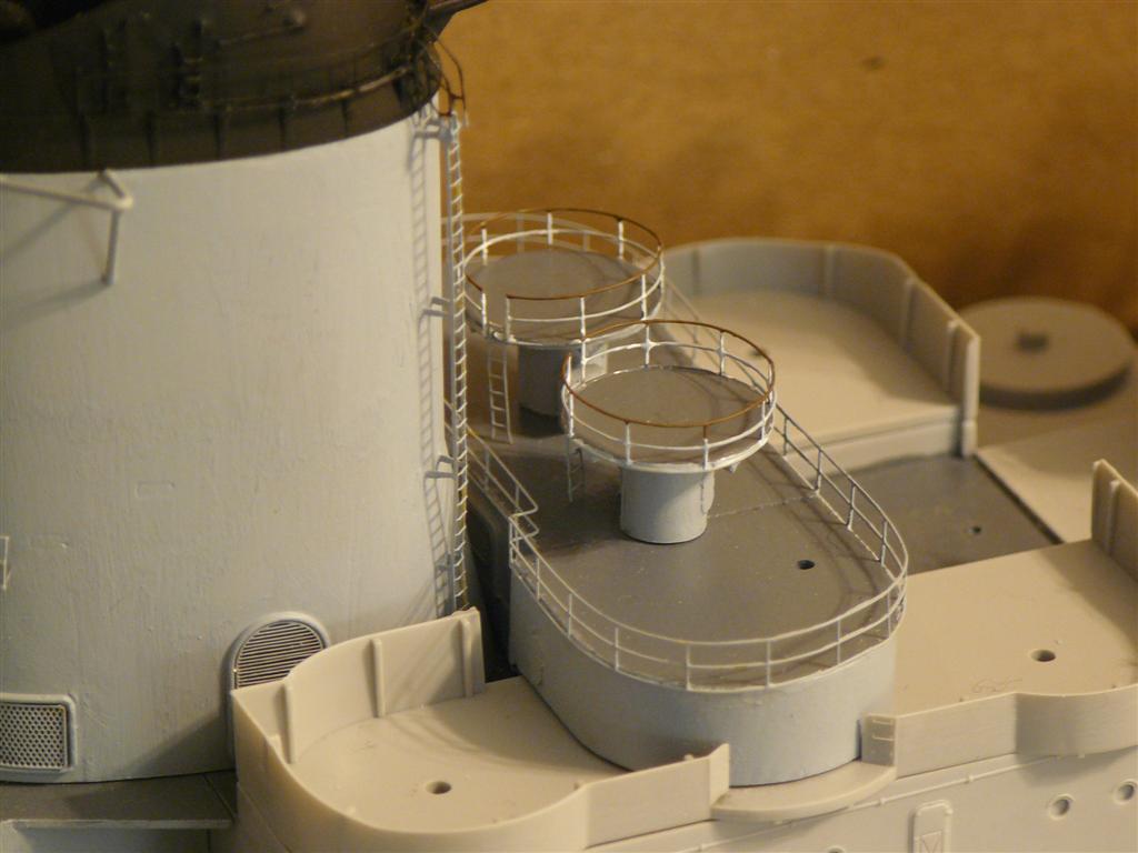
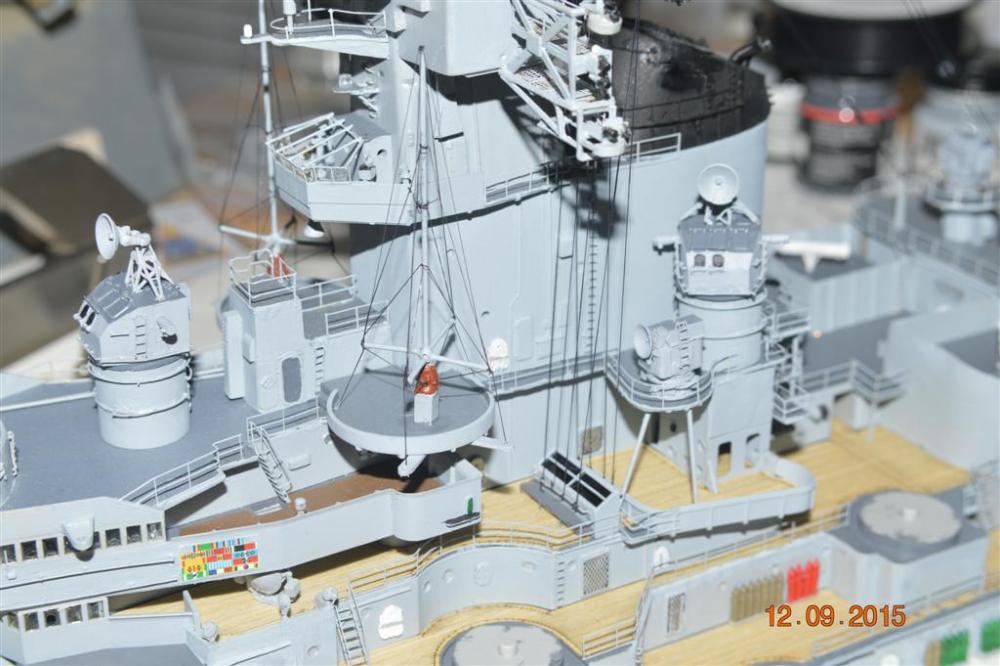
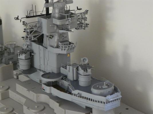
OK, last night I was able to get a shot from the front of the Mk. 56 platform that was IN FOCUS!!! The center bulkheads (fore/aft) are completely scratchbuilt as are the director foundations/bases. Hank

- 187 replies
-
- 10
-
-
- new jersey
- trumpeter
- (and 2 more)
-
First - thanks to all who have commented recently - I haven't been AWOL, just busy So, for a current update - I've been working on the modification of the center 40mm tubs between the stacks and have the basic mods in place. This area is now the Mk. 56 FC Director Platform. As with the rest of the model, it is in place but not adhered at this point. Work to be done on the other 40mm tubs (4) ahead and abaft of this platform. They will become Zuni Rocket Launcher tubs (to be built) and will require minor modifications. As a comparision to the orig. configuration, look at a couple of the photos from earlier posts of this area. I hope to have another photo from the front of the platform later - the one I took last night was out of focus. The Mk. 56 directors are as yet to be built - I need 6 of these, so I am planning on making a master and molding the other 5 - that will be a project in itself. The remaining hole in the decking is for location of the antenna post (each side) to which antenna wires are turnbuckled and attach to the foremast yard. I'm still doing research on the Zuni Launchers so those are not started yet. Photos that I have access to are not close up and details are sparce. Len - do you recall the interior of the nav. bridge? I may have asked before - I was thinking it was pea green on the bulkheads, but perhaps simply haze gray. If you've any ideas, let me know. Hank

- 187 replies
-
- 13
-
-
- new jersey
- trumpeter
- (and 2 more)
-
Popeye, Michael20 - The name's Hank, not Frank! Thanks for the comments! Hank