
CharlieZardoz
-
Posts
969 -
Joined
-
Last visited
Content Type
Profiles
Forums
Gallery
Events
Everything posted by CharlieZardoz
-

Brig USS Enterprise 1799 info gathering
CharlieZardoz replied to CharlieZardoz's topic in Nautical/Naval History
How so you think? You mean the extra yard arms at the bottom that shouldn't be there? The capstan doesn't look period correct either. -
Brig USS Enterprise 1799 info gathering
CharlieZardoz replied to CharlieZardoz's topic in Nautical/Naval History
Last we have the Venice plans by Andrea Salvini which look a bit odd but may very well have accuracy in some of the hull lines. This topic has been discussed before in the forum but would love to get a copy of those as well.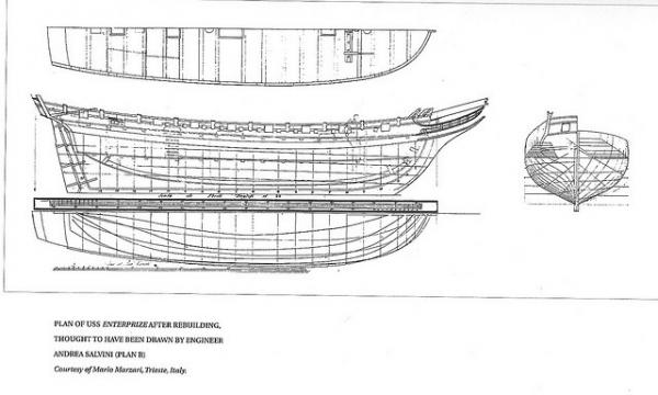
-
Brig USS Enterprise 1799 info gathering
CharlieZardoz replied to CharlieZardoz's topic in Nautical/Naval History
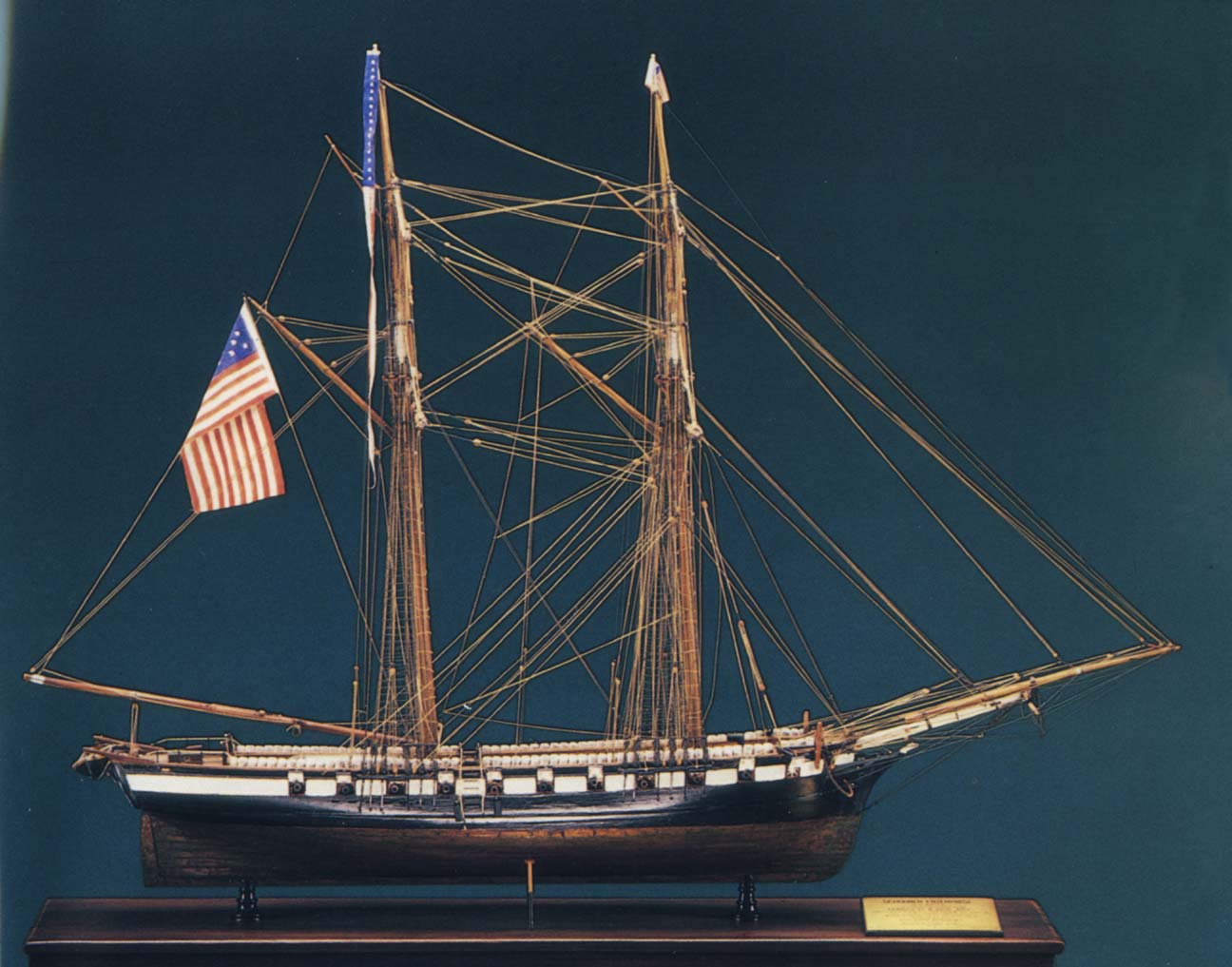
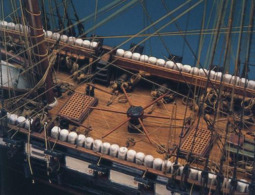
Next we have the model built by Captain Percy Ashley at the Addison Gallery which looks to me like a very close approximation to the lithograph photo shown above if you take into account the placement of the gun ports etc. Something I'd love to visit I wonder how it was built and if plans survive from the process.
-
Brig USS Enterprise 1799 info gathering
CharlieZardoz replied to CharlieZardoz's topic in Nautical/Naval History
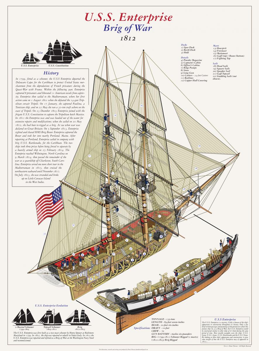
I found a really excellent diagram illustrated by DonnThorson which to me looked well researched and how I would imagine she would have looked like in her heyday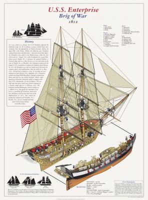
-
Brig USS Enterprise 1799 info gathering
CharlieZardoz replied to CharlieZardoz's topic in Nautical/Naval History
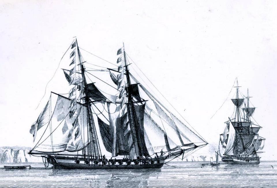
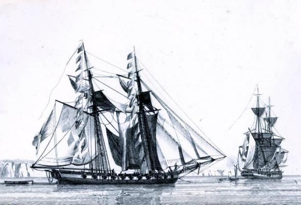
Next we have the two classic illustrations which offer a very good idea of what she looked like overall. One appears to be before the rebuild and the other after when she was rigged as a brig.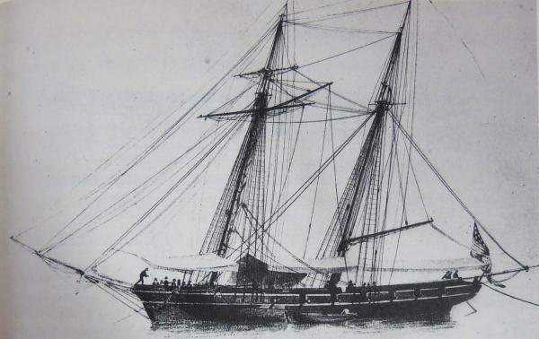
-
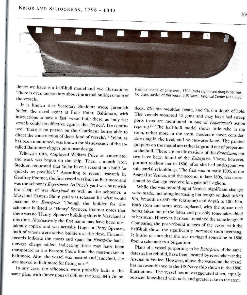
Greetings everyone! Been a bit quiet of late due to the fabulous summer but wanted to start a new post where those interested could gather information on the famous schooner/brig Enterprise. While no plans of her exist, so much secondary information does that I cant help but feel an accurate model could easily be made of her. Please feel free to add any docs/info to this thread though I'm trying to avoid the Constructo model which I've come to feel isn't a very accurate depiction of the ship.This is what I've come up with... enjoy First below we have the half-hull model that exists in the Naval historical center which I'd love to get measurements of. This would be before her rebuilding and lengthening from 84.5' to 92'. I included some of the article from the Canney Sailing Warships book since it's a pretty interesting read.

-
I appreciate the kind words. In all fairness all i'm doing is trial and error and solving puzzles with a little common sense. I've already done some more work on the stern and will post pics once it's to the point where I'm happy. Real Estate is a busy business as is taking the lady to the beach on weekends
-
American sailing warships with no plans or records
CharlieZardoz replied to CharlieZardoz's topic in Nautical/Naval History
A little knowledge of oak species and distribution goes a long way in understanding ship building and its history- 401 replies
-
- 1
-

-
- John Adams
- Alliance
- (and 3 more)
-
American sailing warships with no plans or records
CharlieZardoz replied to CharlieZardoz's topic in Nautical/Naval History
Also what did they use for the Congress and Potomac class frigates?- 401 replies
-
- 1
-
-
- John Adams
- Alliance
- (and 3 more)
-
American sailing warships with no plans or records
CharlieZardoz replied to CharlieZardoz's topic in Nautical/Naval History
Interesting, so they used white oak yes? That would mean their timber was no better than the subscription frigates?- 401 replies
-
- 1
-
-
- John Adams
- Alliance
- (and 3 more)
-
American sailing warships with no plans or records
CharlieZardoz replied to CharlieZardoz's topic in Nautical/Naval History
True true and what about the British? I'd imagine they had a well developed system of growing oak lumber and maintaining its use for ships. I'm assuming that by the 1850's the US must have developed a similar system. Was live oak even used in England?- 401 replies
-
- 2
-
-
- John Adams
- Alliance
- (and 3 more)
-
American sailing warships with no plans or records
CharlieZardoz replied to CharlieZardoz's topic in Nautical/Naval History
Gotcha, I wonder if it's the lumber itself or if it was the fault of inadequate ventilation in the ships interior. -
American sailing warships with no plans or records
CharlieZardoz replied to CharlieZardoz's topic in Nautical/Naval History
Is that also true of the President? She rotted as well according to the British reports. -
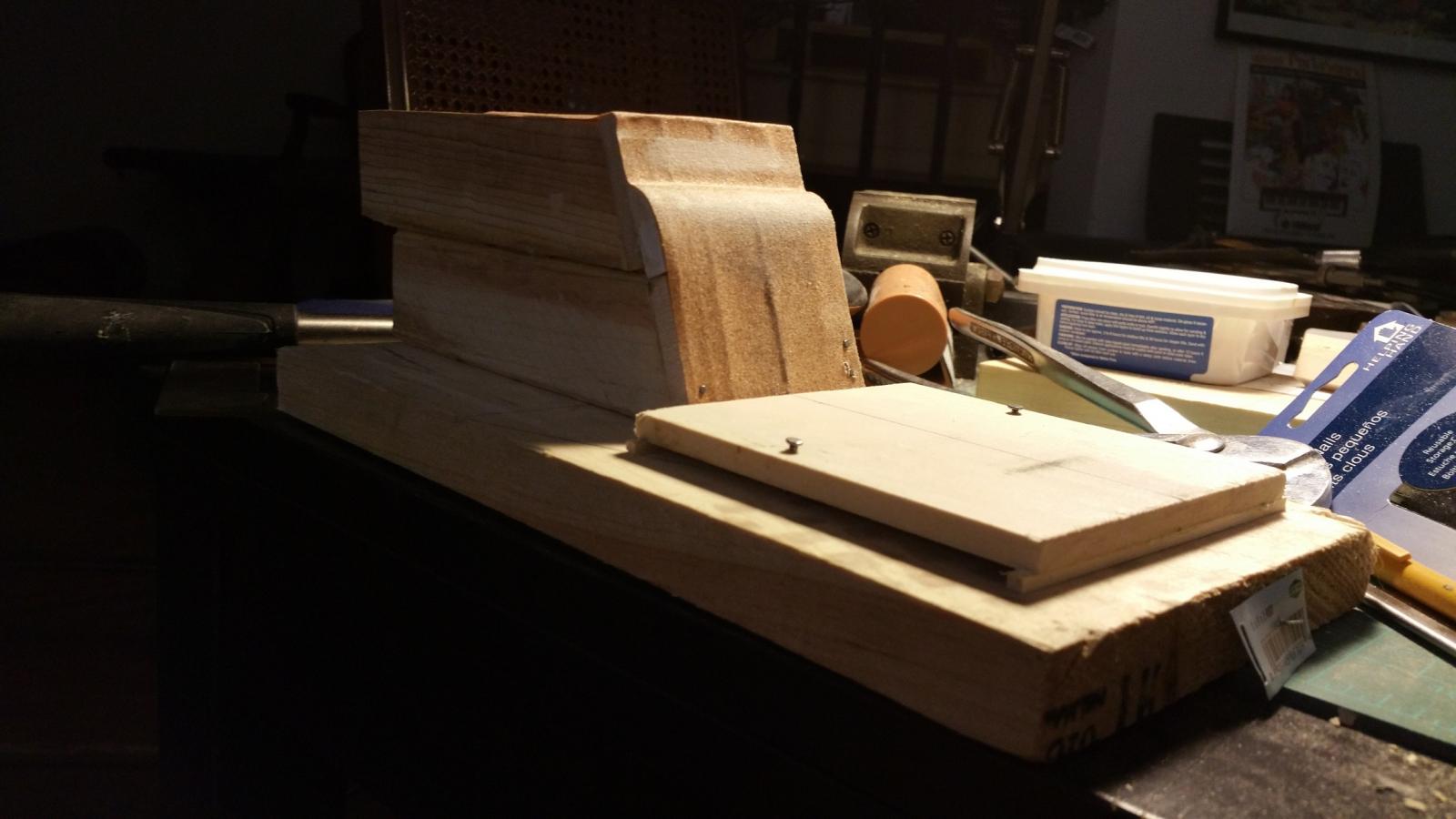
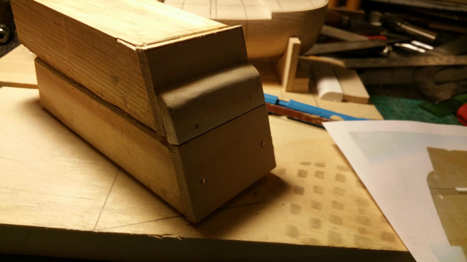
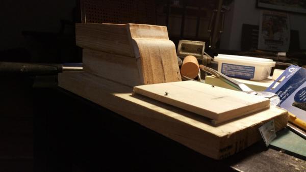
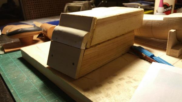
And here's a few more, sandpaper added, and jig level measured to get a general level as to where the hull should stay for sanding.
-
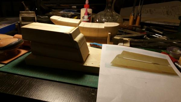
So hi all, just a quick update. This is my interpretation of Hopeful's jig to sand the stern. Basically a few pieces of junk wood glued and nailed together and some wood putty added to shape the curve correctly. While it looks slightly lumpy it will eventually be covered with sandpaper so doesn't have to look perfect. More pics to come!

-
American sailing warships with no plans or records
CharlieZardoz replied to CharlieZardoz's topic in Nautical/Naval History
Here's a few more pics of John Adams but the rebuilt version as a Boston class sloop. Sorry for the lousy quality the pics are very light in the books but you can see she was a totally different design when rebuilt.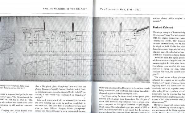

- 401 replies
-
- 5
-
-
- John Adams
- Alliance
- (and 3 more)
-
American sailing warships with no plans or records
CharlieZardoz replied to CharlieZardoz's topic in Nautical/Naval History
Yes back to the John Adams indeed! very interesting notes though I am a bit confused. How many times was she a corvette and a frigate? Sounds like she was converted several times? Also Wikipedia's entry on John Adams is confusing. It doesn't differentiate between the original and rebuilt ship claiming it lasted until 1867 (which I am assuming it was rebuilt the same way Constellation and Macedonian were). If I were to build a model of her it would most likely be as the sleek corvette Also any info on the elusive General Greene?- 401 replies
-
- 1
-
-
- John Adams
- Alliance
- (and 3 more)
-
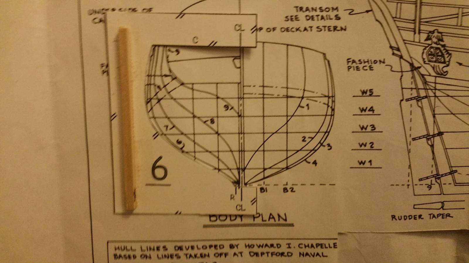
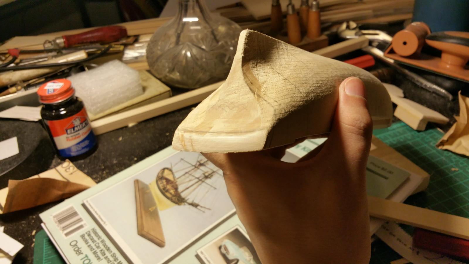
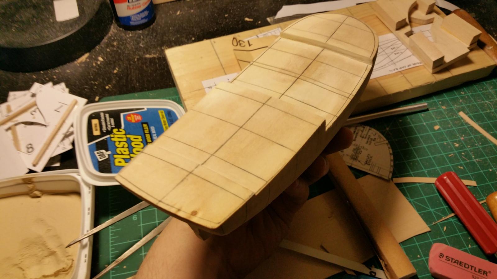
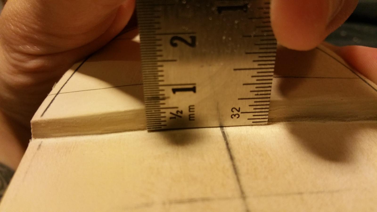
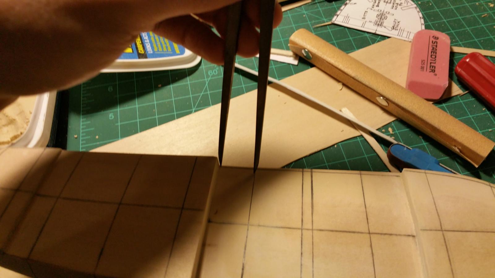
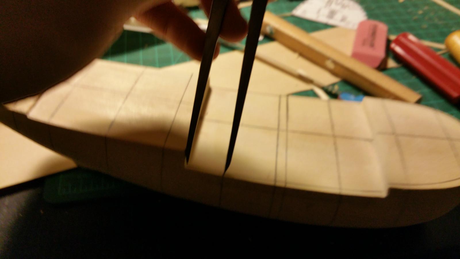
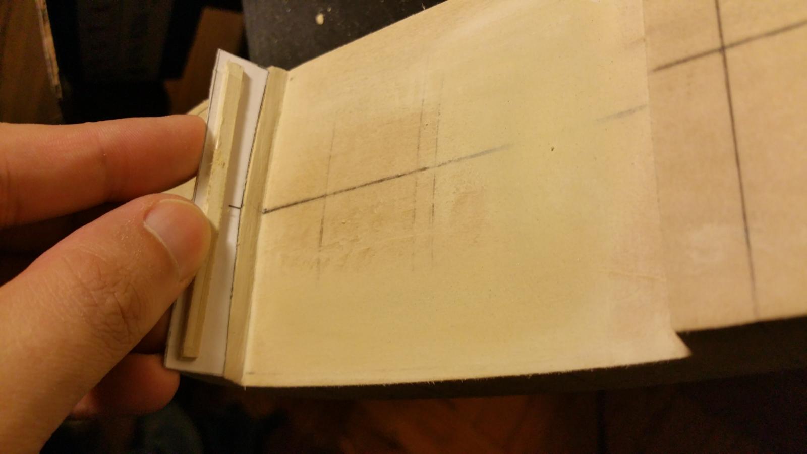
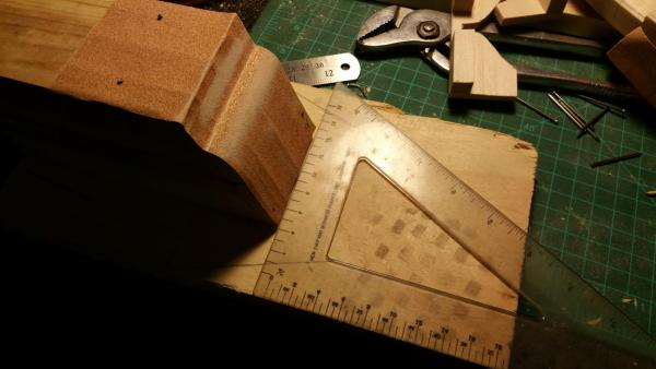
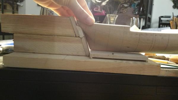
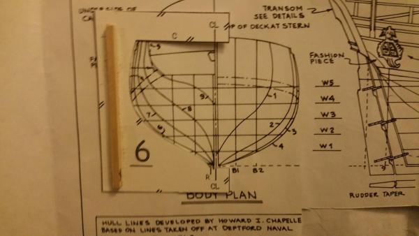
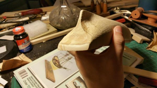
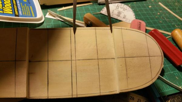
To Bob: Yes I carved away some of the bulwarks then sanded the rest down in order to meet the camber lines. The way they carved the hull looks like the work of a dremel and you can see circular patterns in the carving some of which went a little too far at the edges making the camber kinda "w" shaped. With a mixture of sanding and wood putty I made the curve equivalent to the camber template. The top of the solid hull deck required virtually no sanding so using the tools all I did was sand away from the center to avoid changing the hull shape. It seems each hull is a bit different from each other, if you've been reading Chuck's practicum his was quite different than mine and looking as yours seems different as well. To Michael: Yes I know exactly what you mean. When I lined the templates up from center line to center line the template didn't match the plan lines for some reason so basically I redrew the centerline which lay in between the cl and r (you'll see a tiny dash at the bottom). Most of the people I showed it to said I should throw out the templates entirely but I figured I could maybe salvage them since they had the right shape overall. I added a picture to show you what I mean, however if you see something I don't feel free to let me know. To Mike: Thank you very much for the praise. I'm really enjoying this process overall, each challenge is teaching me something new and getting me ready for the next part of the building process though can't wait to be done with fairing and onto planking lol. I'm hoping one day to make an HMS Badger which looks as good as yours
-
Ok so to make the jig it looks as though the wood blocks need to be cut on an angle of 70 degrees even. Going to get the wood bits in a bit and assemble it same way Hopeful did.
-
Both Chuck's practicum and Hopeful's build log have been invaluable to me in this process. I see what you both mean about the sanding block. I'll have to determine the right angle using the plans and put together some sort of jig which to sand. The back now as it is so uneven. I appreciate the good words and encouragement. Charlie
-
American sailing warships with no plans or records
CharlieZardoz replied to CharlieZardoz's topic in Nautical/Naval History
This is all great stuff. Im going to track down the resources mentioned (page 49) and see. The depection you mentioned with the seven windows and upper deck windows sounds on the mark. That painting posted looks a bit wierd though and yes looks more like the stern for the java class. -
Just a quick question to anyone reading, I want to sand down the rear of the hull but not sure what's a good way to keep the sanding even since it needs to be on an angle as per my lines on the hull. What's a good tool anyone?
-
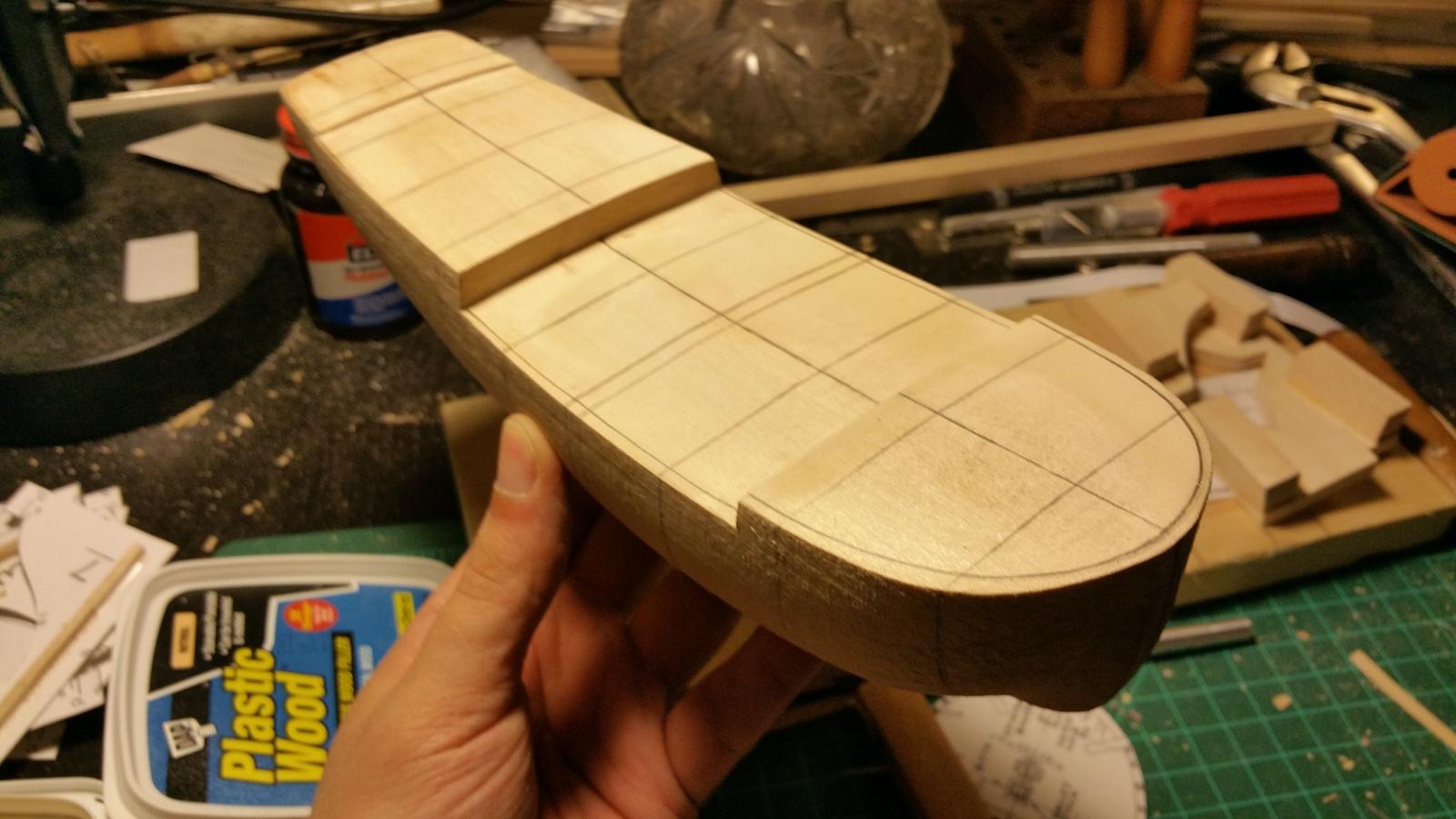
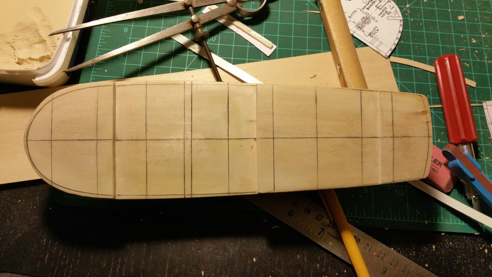
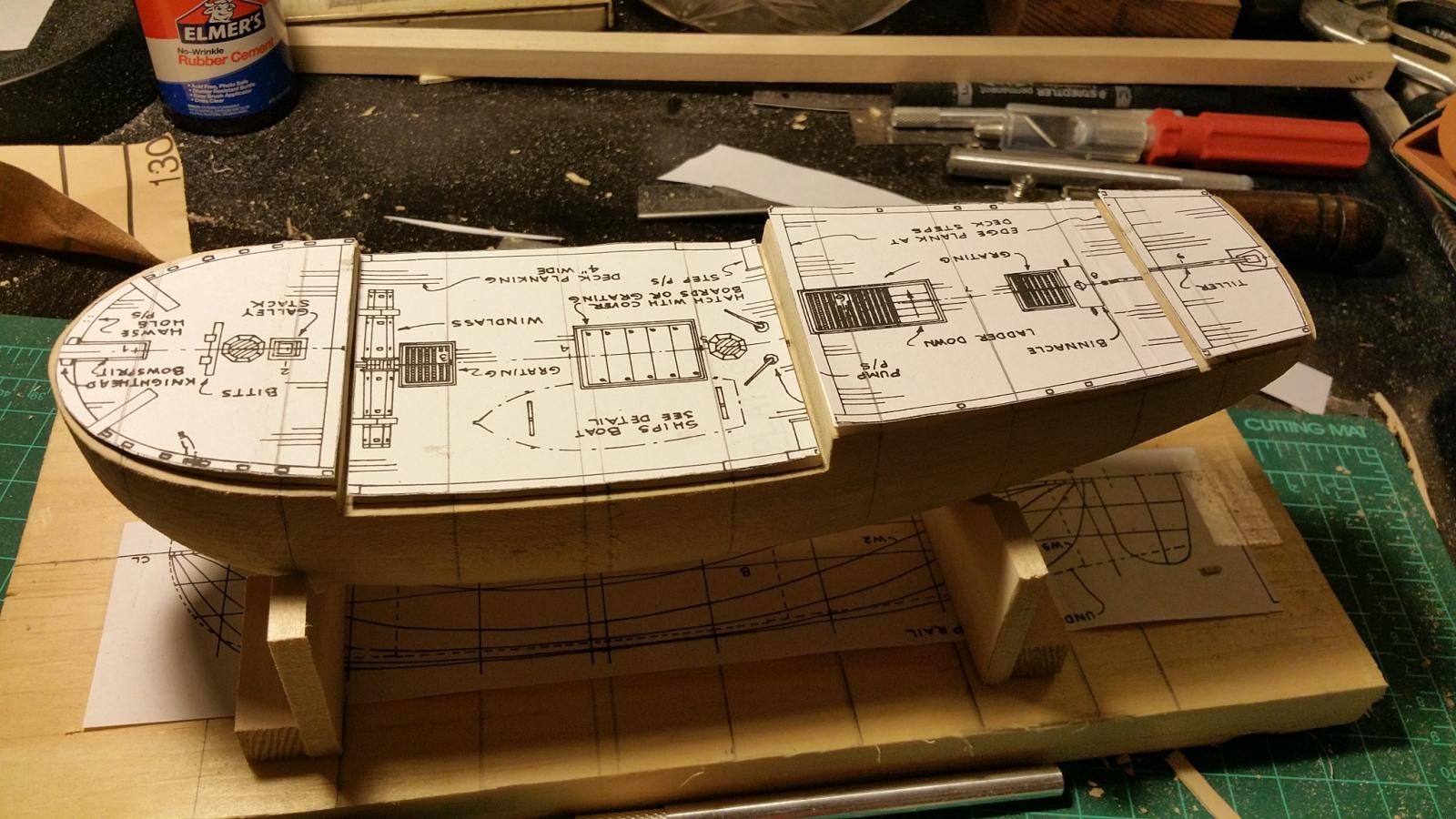
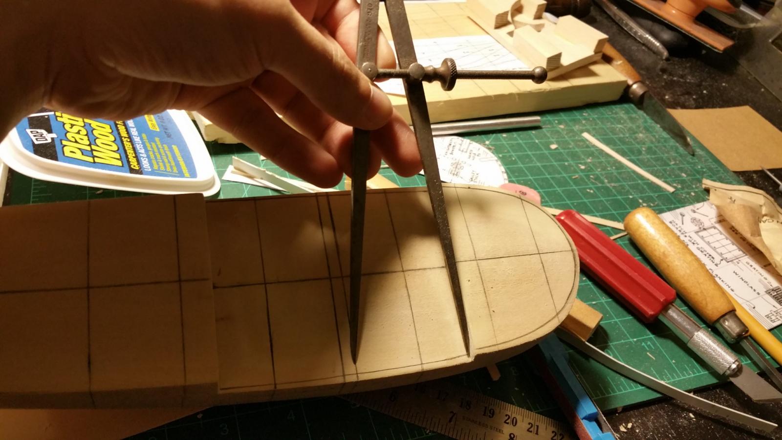
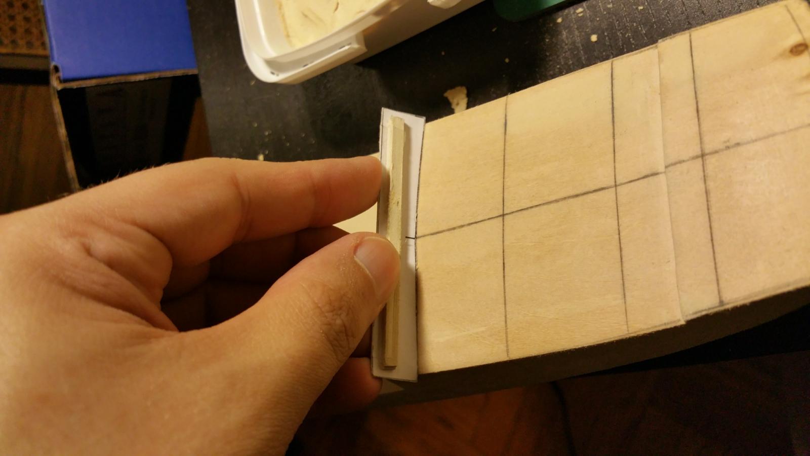
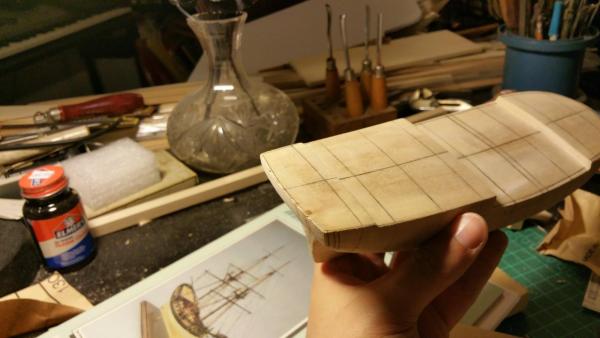
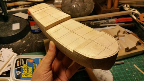
The process wasn't nearly as hard as it sounds but this is the finished result. The top of the hull all nice and even so now I can flip her over and nail her to the board. Note the deck templates laid out, the middle one seems a bit small but that's because the sides of the quarter and forecastle deck's will be planked 1/8" by 1/16" inch planks.


-
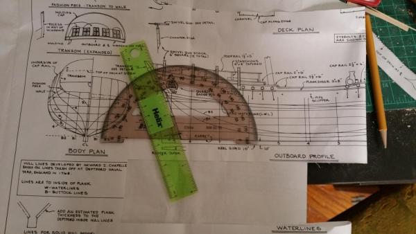
Using a ruler and one of those thingies which name currently eludes me, I kept sanding away the edges with my sanding sticks until the angle was just right, redrawing the lines each time to use as a guide. See how much nicer the camber is now.


-
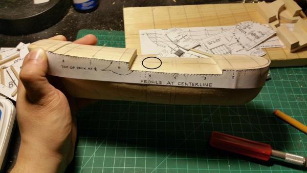
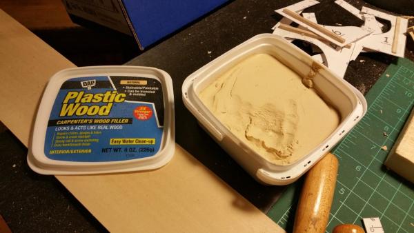
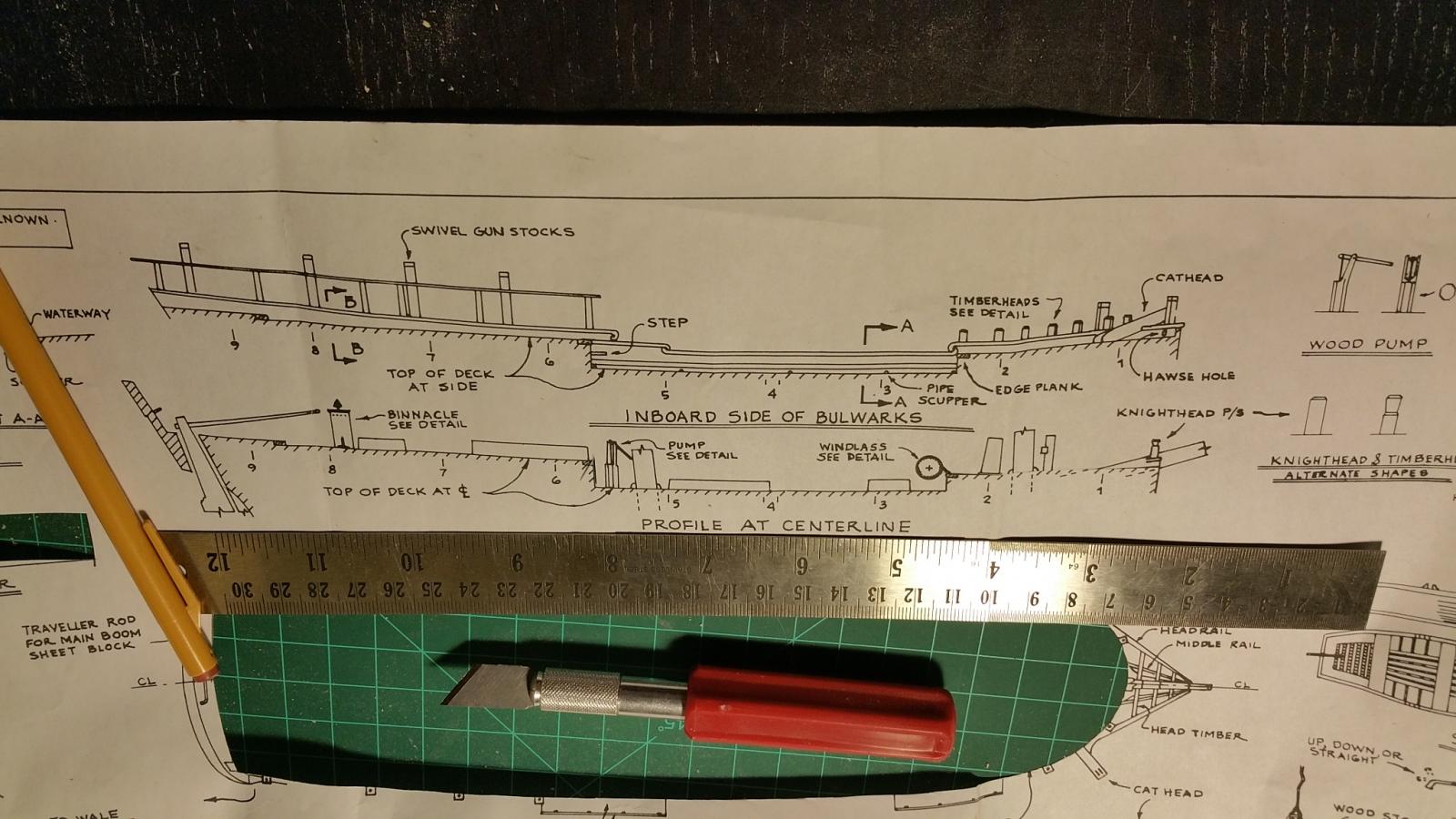
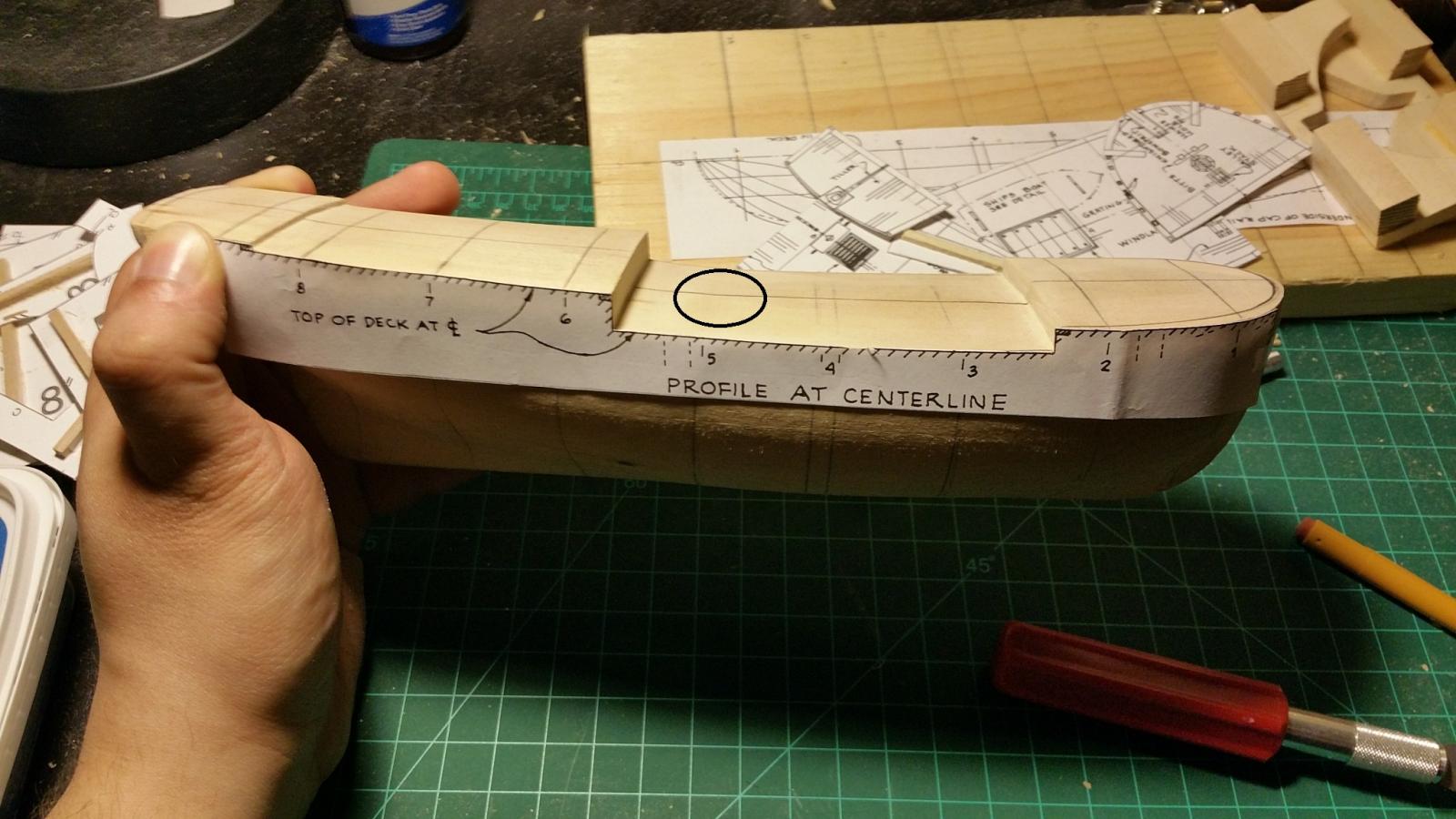
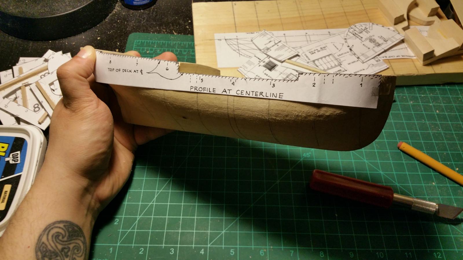
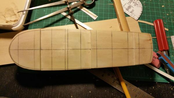
Making the deck look just right requires looking at it from just about every direction, top, forward, backwards and sideways. To help with this process I made another template form the plans. This is a side profile view that shows the angling the deck should run from fore to aft. See the area circled is not even and dips down due to the cutting away of the excess wood. This was easily fixed with wood putty which I apply and smooth out with the good ole' fingers. The method model shipways uses to camber the deck looks like a dremel so while it's pretty close to where it should be, using wood putty ensures the camber is smooth with as few flaws as possible. Doesn't have to be perfect since this will be covered with planking.