HOLIDAY DONATION DRIVE - SUPPORT MSW - DO YOUR PART TO KEEP THIS GREAT FORUM GOING! (Only 13 donations so far - C'mon guys!)
×


ir3
-
Posts
336 -
Joined
-
Last visited
Content Type
Profiles
Forums
Gallery
Events
Everything posted by ir3
-
I just completed the quarterdeck gun ports and I am a bit bothered by the process. There are two sets of laser cut parts for the gun ports, some for the quarterdeck and some for the main gun deck. The number of parts for the quarterdeck is over twice the number needed and it appears that the main deck has a significant number too many. Also, each piece for the quarterdeck had to be custom fitted. Am I missing something and using parts that should go somewhere else? This is a bit confusing for me. Any help? Thanks, IR3
-
The lintels and sills are in and faired. I am about to install the gunport framing vertical pieces. There are two basswood sheets with what appears to be the vertical framing pieces. They are not documented on the plans and not referenced in the instructions. I can't find any other references to using these in the instructions so I am assuming that they are the framing pieces. There are a lot more than are actually needed. Hmm, the camera has distorted the spacing. They are all 3/8". IR3 Found It!! First sentence in the section for gun port openings.


-
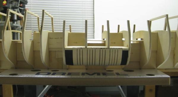
I'm still here. A lot of distractions has kept me out of the shop for a while. Moving along, the Beakhead deck is planked and the beakhead former is also planked. The picture shows the anti twist device, a piece of 1/8 piano wire, in place for the picture. I am keeping it out now since a slight touch of twist in the wrong direction was noticed. With it out, the hull is perfectly straignt. This will go back in as necessary if the hull shows some evidence of the original twist returning. Now on to the gunport openings. Until next time, IR3

-
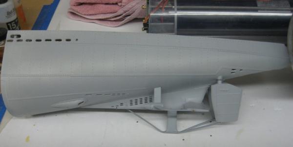
With the mounting tabs in place for the nose cone it was time to get some primer on and after priming, get the rudders and aft planes in place. It looks a lot better in primer. Next Rudders and Aft Dive Planes in place. The space to work in on this sub is quite minimal. The Type VII/C's were quite narrow at the stern. Getting to the grub screws with my meat hooks is very difficult. There is still a bit of tweaking to be done to get the rudders and planes zeroed but that will happen when the RX is put back in. It may look like a lot of space but it is deceiving. The Tech Rack and WTC have been removed for painting otherwise the tail cone would have been mounted with the prop shafts. It appears that the twist in the hull of the Confederacy might have been fixed. If so, it will be back on that project for a while. IR3


-
On Jan 9th I reported that I could not get the twist out and started the process of getting the parts to make another hull. In the meantime I left the anti twist device in the hull and left it clamped in the Dremel work bench. Out of curiosoty I removed the anti twist device this afternoon and I believe I am now ready for the home . With the anti twist device removed, the hull is perfectly straight. :) This is not to say the it will revert over time but just incase I left the anti twist device in and gave it another spraying of ammonia water. Since I am in the process of painting the hull of the submarine at the moment I will leave the anti twist device in for another 48 hours but checking regularly to make sure I do not introduce a twist in the other direction. With luck I will be back on the build in a day or two. IR3
-
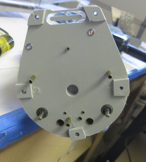
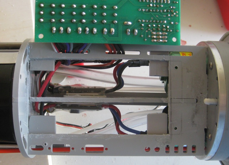
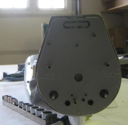
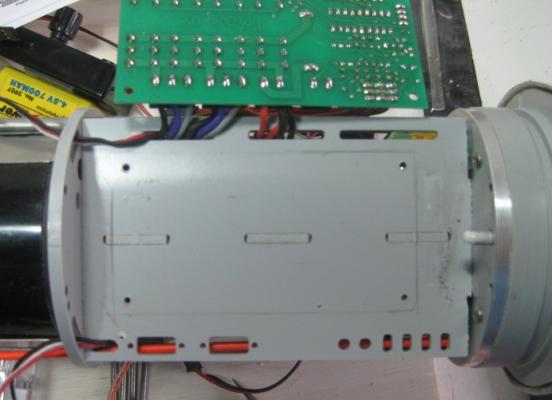
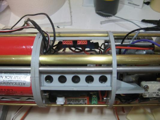
The instructions show the aft section permanently fastened to the rear bulkhead of the Tech Rack. I did not like this since it would make it extremely difficult to do maintenance work on the propeller shafts and the push rods to the aft dive planes and rudder. To solve this problem I decided to bolt the art section to the rear bulkhead using 5 screws. The first picture shows the blind nuts attached to the rear bulkhead. The next picture shows the 5 tabs in the aft section. Note also the guides for the rudder and aft planes push rods. Not too elegant but functional. This basically brings the thread up to date on my progress. Untill next time, IR3

-
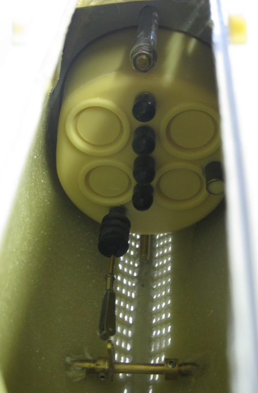
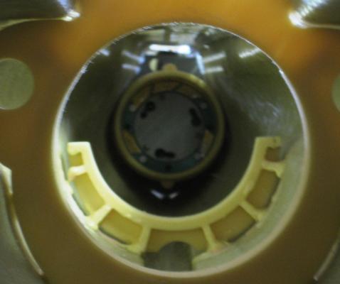
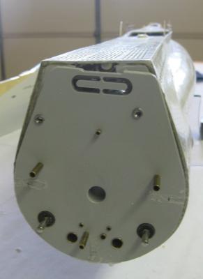
With the mechanical problems in the Tech Rack solved it was time to install the it in the WTC. The next problem and hopefully the last showed up. The bow end of the tech rack has a bulkhead with an O-Ring. This is the forward seal for the WTC. There is a cone in bow that accepts this bulkhead. The bulkhead has 3 adjustable retaining pins and they slide into the cone and with a twist to lock the WTC in place. Well as the first picture shows, there was a bit of a mis-alignment. With a lengthening of the slots in the cone, a correct alignment was achieved. This was not without great difficulties, however. The nose cone is bolted to a bulkhead which is fitted at a specific spot in bow section of the hull. There are two bolts that hold the cone in place. One bolt is easy to get to but the other is tucked down almost against the hull and is a nightmare to get on and off. I tried flexible extensions, magnetic nut holders, modified sockets but could not get this nut on and get it tightened. After consulting others that have built this sub they agreed that one nut on the top should be OK. The object is to keep the nose cone from twisting when the Tech Rack is twisted in. After lengthening the slots, difficult to see, the Tech Rack is aligned. So mechanically speaking, most of the problems have been solved. Please keep in mind that this kit was not a disaster in the making from Engel. I purchased this sub years ago when we had a very favorable Euro exchange rate. My best guess is that the Tech Rack minus the electronics was a very early design. When the kit was shipped, updated electronics were included. It is most likely that the new electronics were not fitted to the early Tech Rack mounting components but mods were made to later kits to correct the problems. Also, I installed two upgrades and had to make the various changes to accommodate the upgrades. It was an interesting experience getting the kit to it's current state. From here on, the updates to the thread will be current. Thanks and until next time, IR3
-
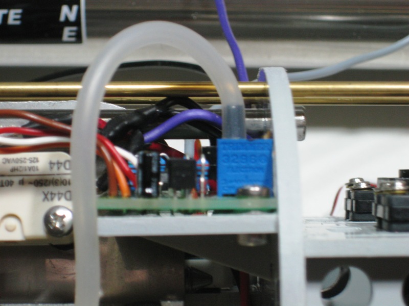
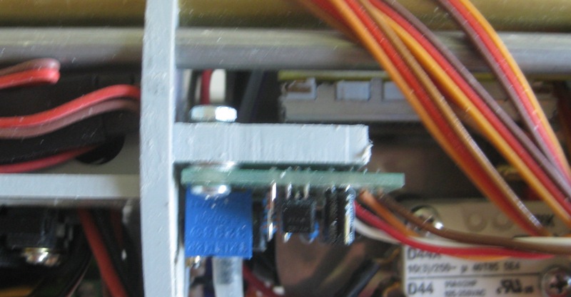
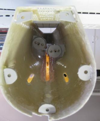
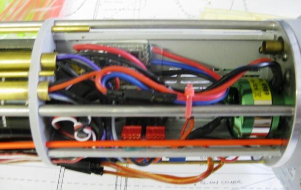
So now things are really looking up. Most of the electronics have been updated, there is room to make maintainence a bit more easy but yet another problem shows up. The Engel electronics package is very sophisticated. During the initial installation of the components I learned a bit about how they work but since I am still in the construction phase, there is a lot more to learn. Very sensitive pressure sensors are in the electronics package as well as level sensing or inclinometer sensing. You can set the boat to run smoothly at Periscope depth. Once partially or completely submerged it is very difficult to keep the boat level from the operators standpoint. The electronics package is tied into the bow and stern planes to constantly make corrections to keep the boat level. This is over ridden when the operator decided to continue the dive or come back up. It goes on and on. Many fail safes built in. I will elaborate as I go through all of the testing and calibration. There is a shelf for one of the pressure sensors. The location of this shelf was probably for an earlier version of the sensor. The TAES is programmable from the transmitter and when activated remembers the static pressure at a particular depth. When the sub has no forward motion at depth, this little gadget continuously adjusts the forward and aft ballast tanks to maintain level. The original location for mounting the part did not allow a smooth bend in the tubing coming from the pressure sensing port. This shelf was moved to allow a smoother run of the tubing. It is a bit difficult to see but the tubing will be kinked when the Tech Rack is slid into the WTC. This picture, although not very clear shows the TAES remounted with the tubing now inboard and a smooth run to the sensor port.. There is one more problem area that will be covered in the next post. Until next time, IR3


-
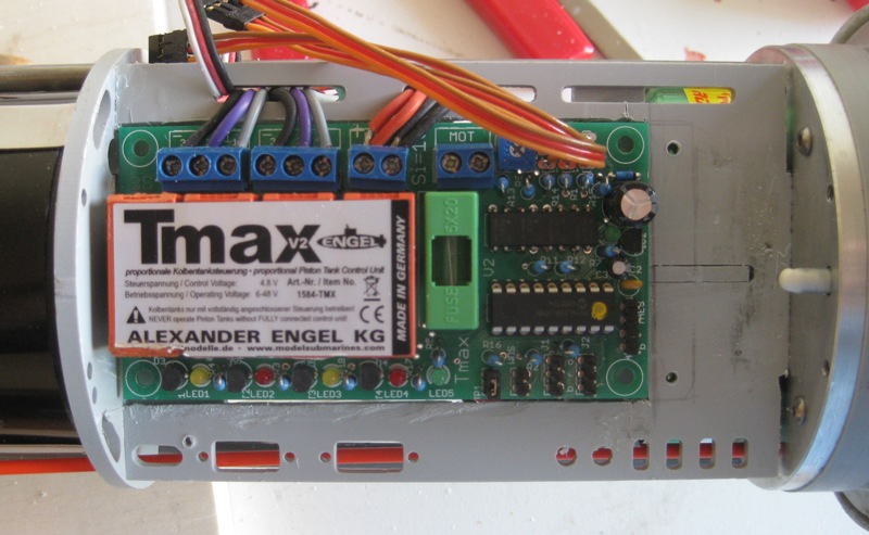
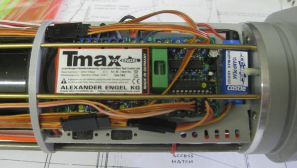
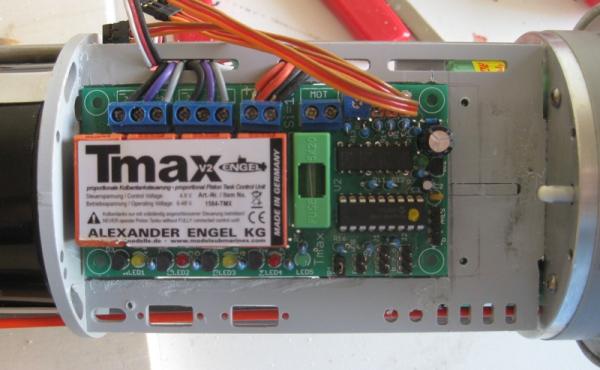
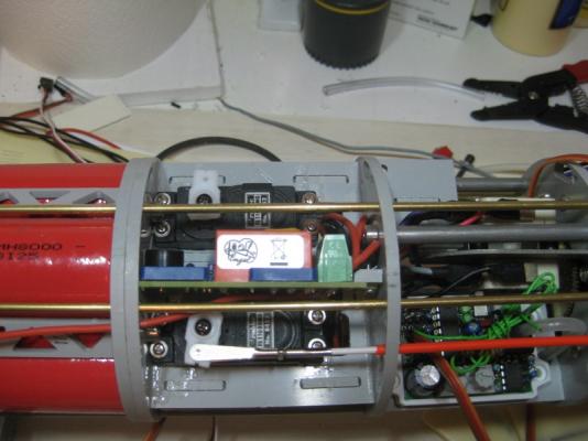
So after getting C cells in, the Brushless Motors and ESC's in and everything starting to look good, uh uh. The brains of the dive system is the TMax VII. This mounts on a platform above the motor/esc compartmant. Well it was a tad too tall and two of the long threaded rods which help keep the long Tech Rack stable interferred with the mounting of this unit. Another modification the the shelf to safely hold the TMax in place needed to be accomplished. This required cutting out an area the size of the TMax and recessing it about 1/4", the thickness of the mounting plate. This picture shows the interference. The next few pictures show how the problem was corrected. And finally the TMax unit comfortably in place. Note that the BEC is no longer mounted. So now things are looking a lot better for the Tech Rack but there is more to come. Until next time, IR3

-
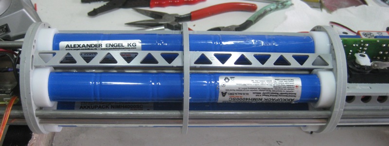
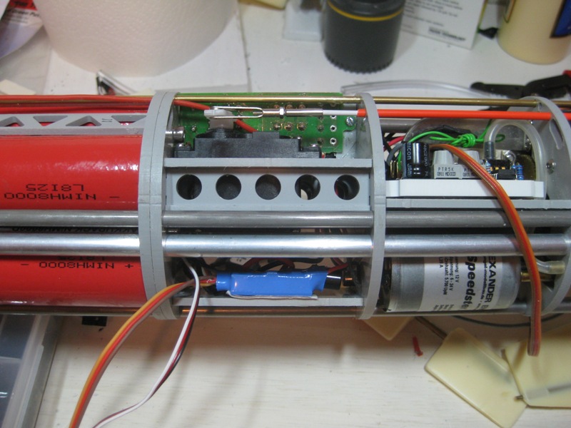
So now everything has been packed into the Tech Rack without a bit of space to spare. Then along comes the Brushless Motors and the Super C battery pack. The nice thing about the new C cell pack is a 4.8V tap is provided. This gets rid of the BEC and a bit more room. Next comes the Brushless Motors and the ESC's. The motors are shorter than the brushed and the ESC's are smaller. All of a sudden space is opening up at the aft bulkhead where the motor shafts exit the WTC. I was now able to move the charge/run sockets to the area near the Brushless Motors and the wiring was greatly simplified. The new battery pack is lighter so some fiddling with the ballast will be necessary. The magnetic switch was moved to a better spot where it can be sensed through the hull with a fairly strong magnet. The Tech Rack at this point in time is now looking very functional and not so packed. Until next time, IR3

-
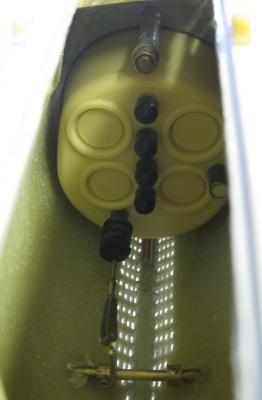
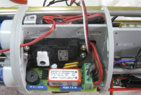
All of the electronics are mounted in what Engel calls the Tech Rack. The Tech Rack slides into a Lexan tube and with O-ring seals on each end of the Tech Rack, the Lexan tube becomes the Water Tight Compartment (WTC). In the original electrical layout, there were no provisions for switching power on/off. This meant removing the Tech Rack from the WTC to disconnect battery connections. The first change that went into the Tech Rack was a magnetic switch that allowed main power to be turned on/off which was great for interday sailing/submarining. The pictures show the installation of the Magnetic Switch and the battery pack with the old D cells. Note that this upgrade was made before changing to the C Cells and Brushless motors. Until next update, IR3 AND OH YES, THE ORIGINAL BATTERY PACK CONSISTED OF TWO 5 CELL PACKS CONNECTED IN PARALLEL. A DEFINITE NO-NO. IF THERE IS A SLIGHTLY WEAK CELL IN ONE 5 CELL GROUP IT PULLS DOWN THE OTHER 5 CELL PACK. THE TWO RED CONNECTORS ALLOW ME TO PUT JUMPERS TO PROVIDE POWER TO THE MAGNETIC SWITCH AT THE POND AND ALLOW THE INDIVIDUAL 5 CELL PACKS TO BE CHARGED INDEPENDENTLY. WHAT WERE THEY THINKING AT ENGEL?

-
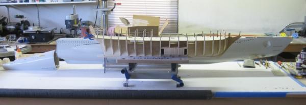
The Engel Type VII build has been going on for some while with the main thread on RCG: www.rcgroups.com/forums/showthread.php?t=1819581. My intent on that thread was to show only the differences in my build compared to most of the existing build threads. Two upgrades that were not covered in older threads are changes to brushless motors for the twin shaft drive and the battery pack from D Cells to Super C Cells which have twice the power in a package that is about half the size. It took many months to get the upgrades from Engle and the battery pack required another set of upgrades. In time I will summarize what I have done up to now but first a comparison to get an idea of the size. The Tail Cone is off the sub but is shown in the approximate position to get an idea of the total length. Until next update, IR3
-
The replacement parts list has been sent to ME and it appears that it might be some time before I receive them so I am back on the submarine project for a while. The build log is on RCG: www.rcgroups.com/forums/showthread.php?t=1819581. I will be starting a thread here which will pick up at the current state of the build. Thanks for the input up to now and as soon as the parts are in things will again move forward. IR3
-
Thanks for checking Augie. I believe that everything I will need is covered in my last post and it has been sent to ME Parts. Iran
-
Need help. I am having a problem determining which laser cut sheets to order from ME. The sheets that came with my kit have no WP numbers on them and no letters A - Z laser printed on any of the sheets. I can only identify the sheets by the thicknesses. I am sure I need A - G but I think on of them is a small sheet with the boat stand parts. I think the false deck sheets are V and W. The Shadow Box frame locators were cut on a separate small piece of 3/16 because the originals were not cut properly on the big sheet. These were on sheet B but were not cut properly. The keel and bulkheads must be A - F. I no longer have the keel and bulkhead scrap. The keel and stem timbers are on a 1/4 basswood sheet and could be either H or I. The exposed frames are on a 3/16 sheet and this could be G. The beakhead frame as well as some of the bow fillers and tramsom pieces are on a 1/8 basswood sheet and could be J or K. The stern framing pieces are on a 1/8 basswood sheetand could be J or K. After looking at what I need it appears that there is no ambiguity but if someone could confirm, it would be great. Otherwise it appears that I need the following: A - K and V - W. Thanks, Iran
-
Hi Ben, The twist is quite prominent from the mid frame back. I believe the error started when I attached the keel. The keel pieces were not square. My error. I should have made sure of this when I removed them from laser cut sheet. Once the keel was glued in place clamping the keel to put the formers in probably introduced the slight twist. Of course each frame went in dead center and square to the bulkhead former but the twist was surely still there. Then came the filler blocks which also went in just fine. I did mount the beakhead former a bit out of line but corrected that assuming it was an optical illusion when I sighted down the hull at that point. It was after I assembled the transom that the glaring twist showed up. At that point I guess it was too late. Lesson learned. I am sure I can get the pieces I need from ME and start over again. Thanks for your input, Iran
-
Thanks Augie. I did try over the last 24 hours to do several applications of Windex Ammonia and twisting the hull but to no avail. I think that once the fillers blocks are in and the deck fastened the chances of untwisting the hull are close to zero. I checked with Chuck and we sort of agree that I should build a new hull. I know what my mistakes are so the second one should be close to perfect. I am checking in with Model Expo to see if I can get the laser cut sheets that have all the hull components. We shall see. In the meantime I am back to working on my Engle Type VII submarine. I wonder if this forum could use a Submarine Thread. I will stay up to date as events unfold. Iran
-
I just started reading ahead and if I start on the gun port framing I am just adding to the problem. I will then have to not only take out the twist in the existing hull as it is now but I would be making the problem worse by adding the port framing. If anyone has a suggestion at this point I would sure like to hear it. I could dampen the entire keel bulkhead and try to fix the twist while wet but I did not use waterproof glue so that might not be such a good idea. HELP!!!!!
-
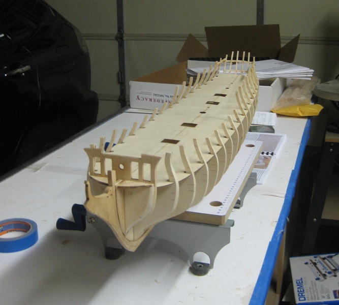
I installed the false deck. There was still some twist in the hull and so before installing the deck I added a jig to take the twist out. With the jig in place the twist was out completely and I thought that installing the deck would fix the problem. It did not. My only hope is that when I get to planking the hull I will put the jig back in place and hopefully after installing all of the upper planks it will be enough to prevent the twist from returning. The actual installation of the deck followed the instructions pretty closely with slight sanding of the slots to get a good fit. I will be planking the aft side of the beakhead bulkhead (that's a mouthfull) with basswood but hold off on the forward side and the small deck until I receive my boxwood order. That is slated to be sometime after March 24th but there is a bit of work to accomplish befor then. I will also be sharing a good part of the time with my "BIG BOAT", an Engel 78" German Type VII static diving submarine. I just received a part that I have needed since April and can now get back on that project. That hull is not twisted! The link to the thread is http://www.rcgroups.com/forums/showthread.php?t=1819581. The thread is to show differences from the standard build to a modified build. Until next time, IR3
-
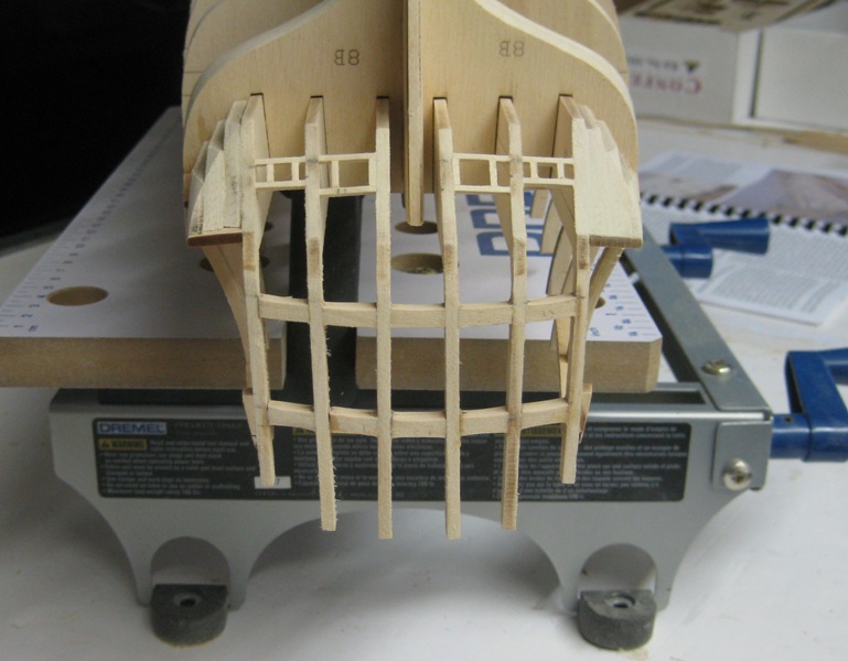
Back to the build after several days of thing to do around the house. The stern assembly is finished and was not an easy thing to accomplish. With my eyesight and lack of ability to read a ruler it was a chore. The next step in the instructions is to add filler strips to aid in the planking and then the false deck. I still need to paint the exposed areas above the lower decks black. Until next time, IR3 A PICTURE SURE SHOWS LITTLE ERRORS. ONE OF THE OPENINGS NEEDS TO BE SQUARED UP. WILL DO THIS IMMEDIATELY.

-
Bingo, I think I found the source of the problem. Bulkhead G was installed slightly skewed off the center line of the bulkhead former. This gave the illusion that the hull was twisted. The eyes can play funny tricks sometimes. I have bulkhead G removed with all of the fillers. After some sanding I can put it all back to gether and get on with the build and some peace of mind. IR3
-
I think I have found a solution to the problem. I hope the explanation is sufficient. I plan on using a piece of 1/8" music wire. It is very stiff and should make a good torque rod. There will be a 1.5" bend at both ends and be placed into 1/8" holes drilled at either FR1,FR2 and FR6. The wire will be below the deck and will only be visible through one of the deck hatches. This hatch I can keep covered. With the proper amount of reverse twist in the wire I believe I can correct the twist in the hull. The twist seems to start aft of the center bulkhead. More to follow. IR3 An afterthought. The wire can be removed once a sufficient number of planks have been installed.
-
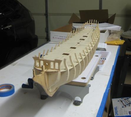
I have just discovered what could be a major problem. I started working on the stern and something caught my eye. I noticed a slight twist in the hull. The hull is perfectly straight longitudinally but the twist is there. When I assembled the bulkheads I thought I had the bulkhead former perfectly straight and flat but I guess it wasn't. The question is, should I continue putting in all of the of the gun port framing and other framing pieces into the hull or should I make a special jig correct the twist and put a group of planks on both sides of the hull. I figure it shouldn't take more than 8 to 10 planks on both sides to hold the hull straignt once removed from the jig. I would sure like to hear from others who may have run into this problem with this or any other build. Worst case is the slight twist stays and hopefully not too noticable. Thanks in advance, Iran
-
Bingo, made it to the start of Chapter 3 (page 13). The sanding of the hull is nearly complete. The bow and stern sanding will need some fine tuning once I get close to planking. Now it is time to have some fun with more construction. I sure am glad the other builds are a lot further along. A wealth of knowledge and building skills. Until next time, IR3