KeithAug
-
Posts
3,266 -
Joined
-
Last visited
Content Type
Profiles
Forums
Gallery
Events
Everything posted by KeithAug
-
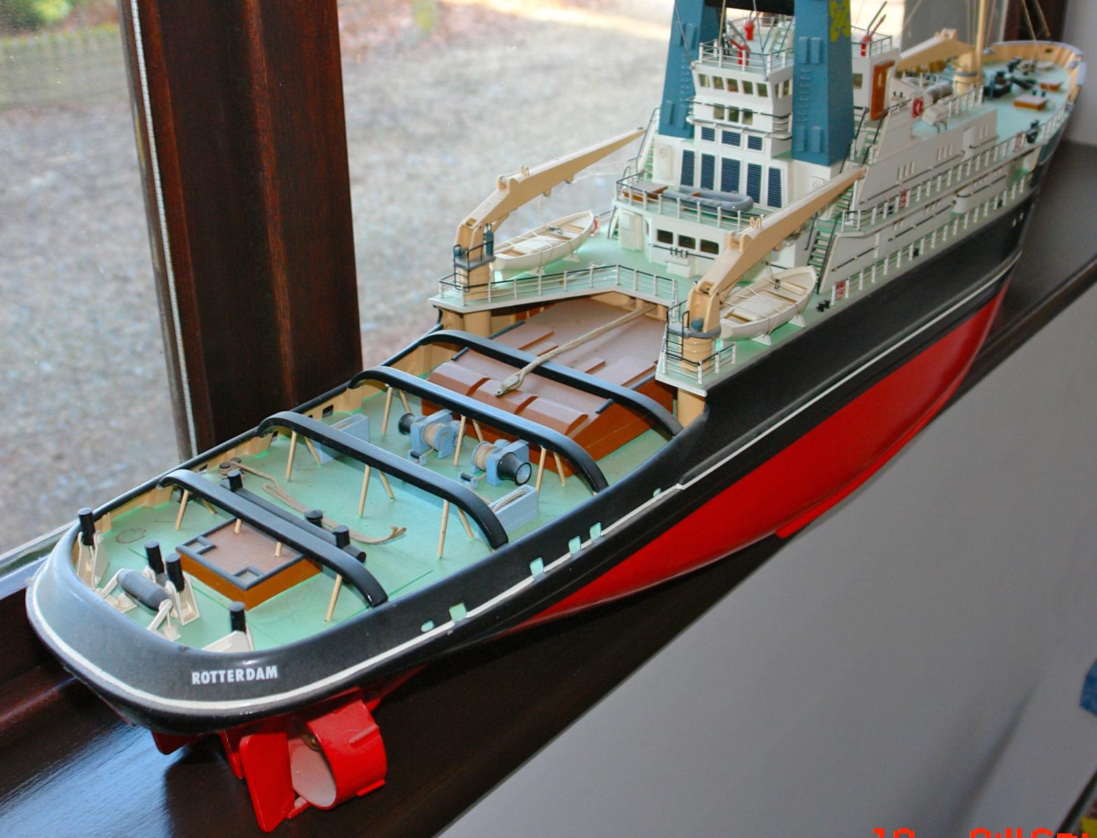
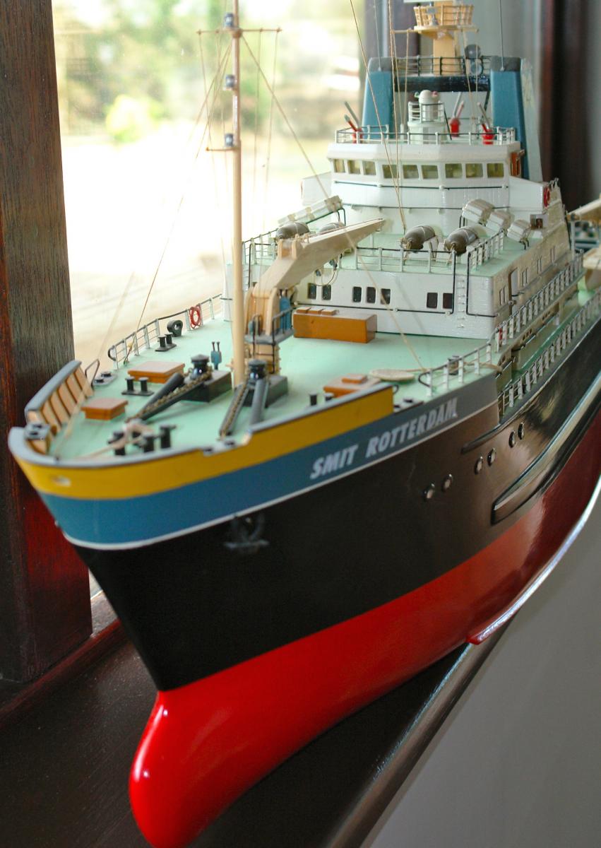
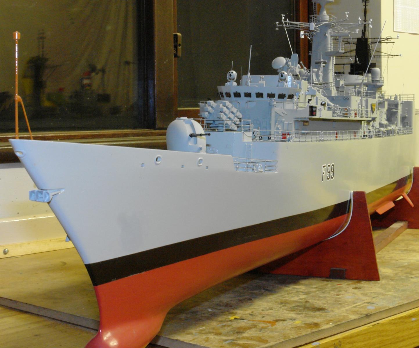
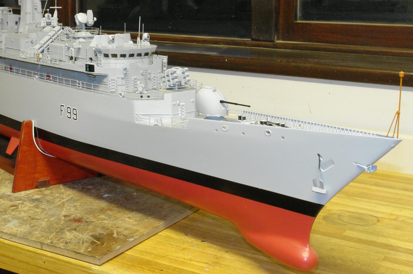
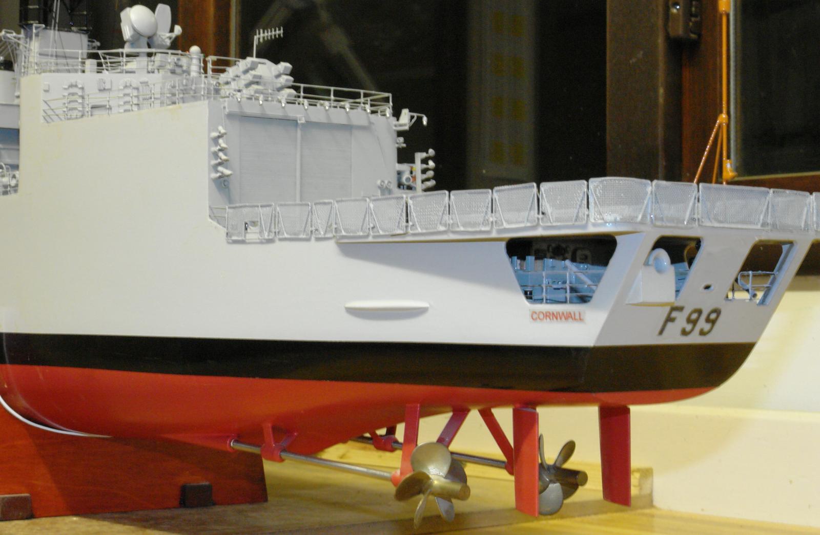
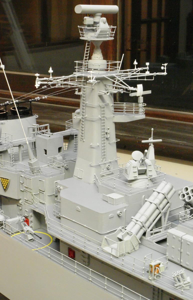
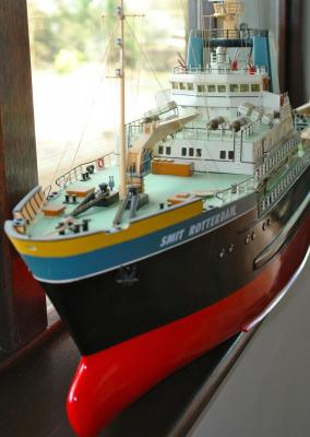
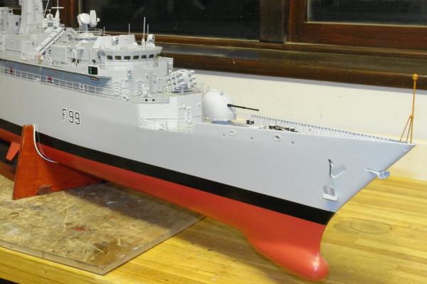
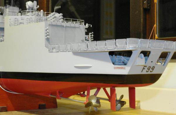
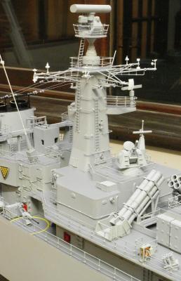
 Reflections - Overview:- I think the Amati Endeavour kit provides a good challenging option for the competent less experienced builder. The laser cut frames and comprehensive nature of the kit contents, together with good quality plans enables the builder to make rapid progress - always a benefit for those who might become daunted by the size of the task. Seeing the hull develop quickly is good motivator, inspiring the builder to return frequently to the build. Had I stuck to the 1934 kit design I am sure that I would have been more than happy with the result. Instructions:- I found the build instructions supplied with the kit to be rather brief and I am sure that an inexperienced builder would have struggled. I think a more detailed explanation would have proved beneficial. Inadequate aspects of the kit:- 1. I thought the drop keel and its mounting was poor and much too flimsy for a quality model. 2. I thought the spacing of the frames in combination with the thickness of the planks would make achievement of a shapely hull profile problematic. I note other builders have sanded through the 1st planks when attempting to achieve a reasonable quality finish. 3. I wasn't very impressed with the quality of the deck planking. To me it felt too open grained. 4. The suggested method of creating the rudder seemed daft and the rudder profile didn't match the hull lines as well as I would have expected. I ended up modifying the shape to make it look right. Good aspects of the kit:- I felt that the fineness of the hull lines (with smooth transitions between frames) did a lot to make the planking much easier than on my previous builds. My first significant build was Billing Boats Smit Rotterdam and the complex hull curvature made for quite a taxing planking operation. My second build was a scratch build model of HMS Cornwall which was easier to plank but still more difficult than Endeavour. I have included a few photos for interest. My view is that Endeavour provides an excellent challenge for those branching out into hull planking for the 1st time, but i would recommend providing a backing to the 1st planks to compensate for the issues mentioned earlier. I was particularly pleased that the mahogany strips provided with the kit as they gave a rich deep colour once varnished. Although I doubted the segmented approach to the mast it actually worked well. I really liked 1:36 as a modelling scale as it gave enormous scope for creating detail. My previous builds have all been at smaller scales - 1:96 and 1:72. I think my future kits will all be at larger scales although I accept this will limit the scope of what I might attempt. I really liked building a yacht. I have sailed for 34 years and building my own yacht seemed, in a strange way, to connect me more closely with pleasant memories. (I can highly recommend the rum punches, lapping waves and inspiring sunsets at Basils Bar on Mustique). Kit or Scratch? I went down the kit route somewhat in haste. I suspect that at least 1/3 of the expenditure on the kit still resides within the box as I have all of the deck fittings / deck houses left over. Kit building also caused me a few frustrations when I didn't like the materials supplied - e.g. the thickness of 1st and 2nd planks, the quality of the deck planks and mahogany ply (warped). In retrospect I should have gone down the scratch build route based on the Amati plans which can be purchased separately and which are clear and comprehensive. What next? I am being lured in by the grace and beauty of Altair - another British Yacht of the 1930's. A comprehensive plan set is available from a number of suppliers and Santa's bag need filling!!!!! Thank you to all those who have taken an interest in this topic.
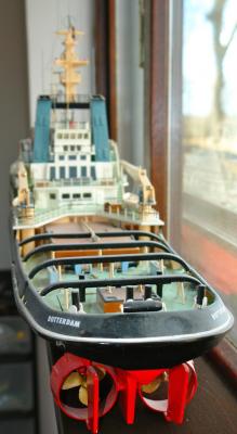


-
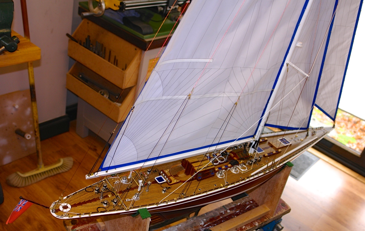
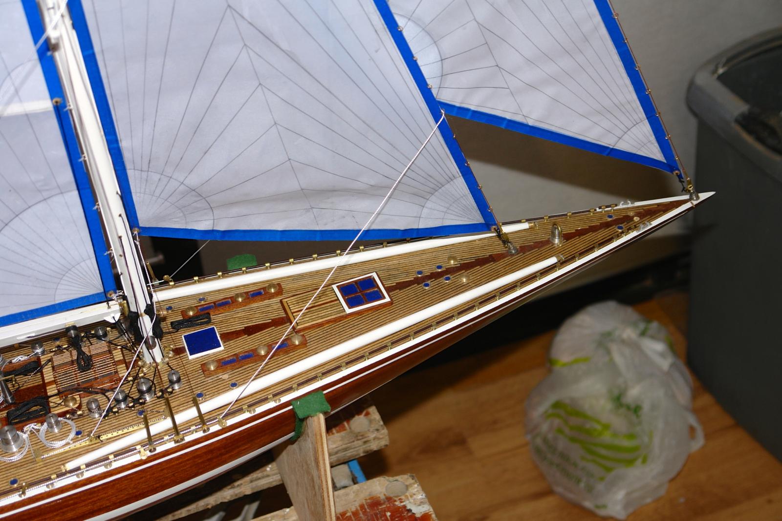
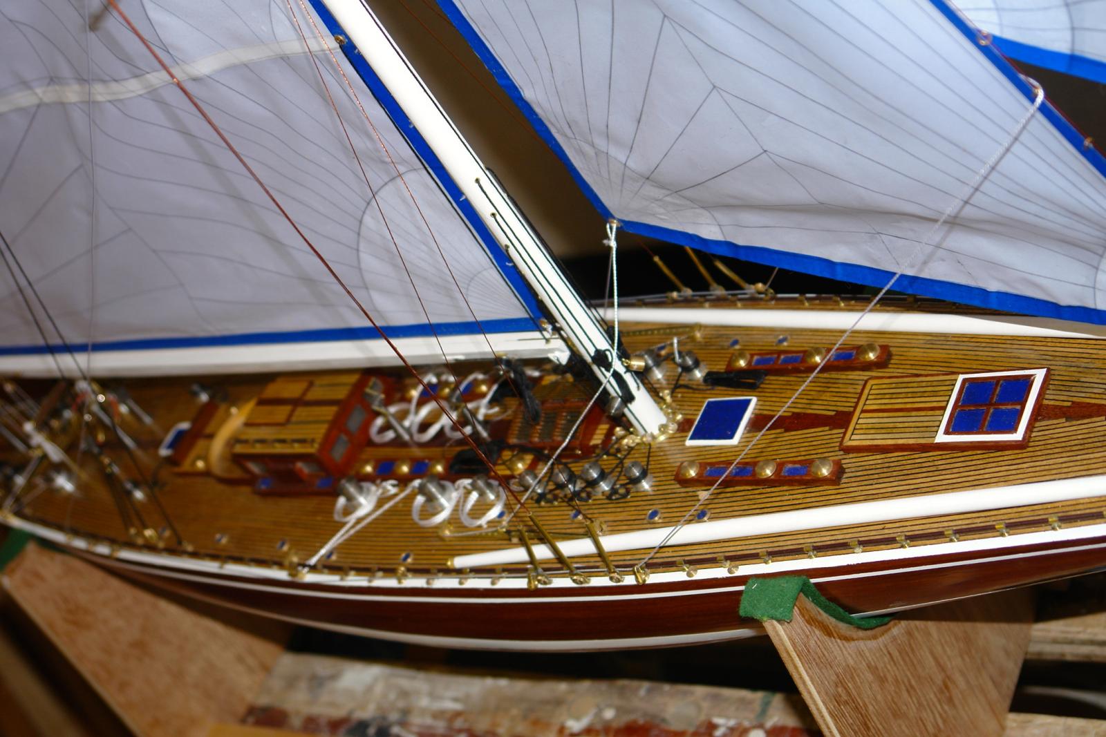
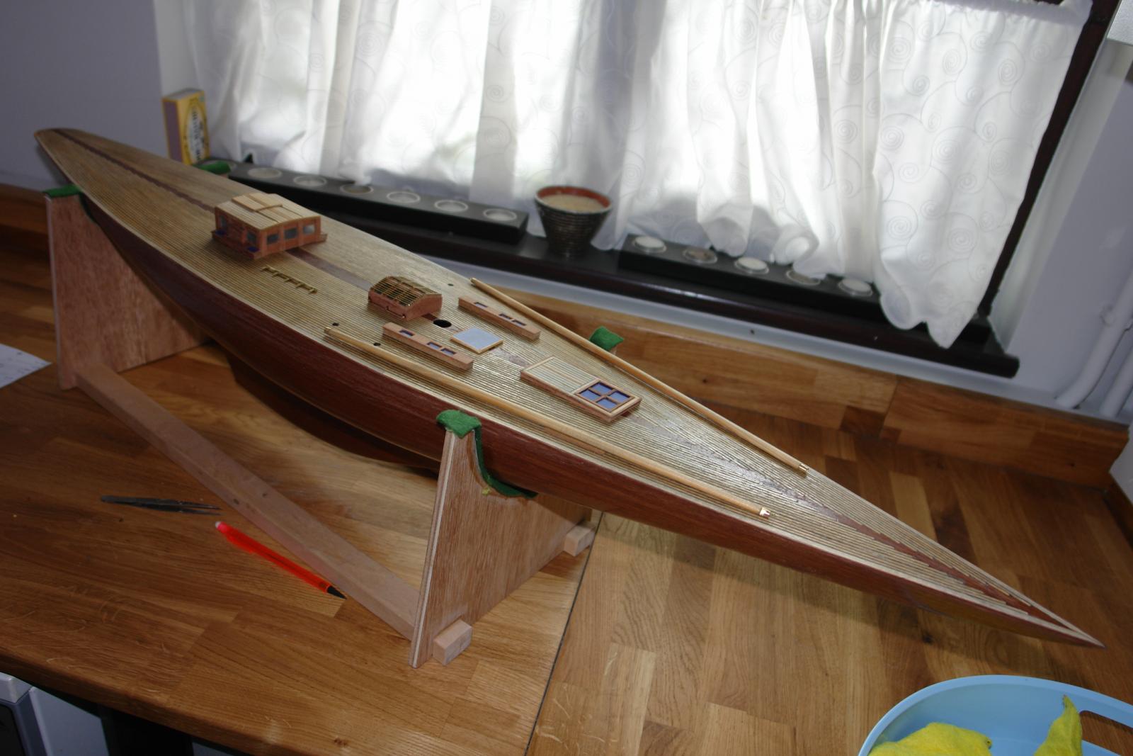
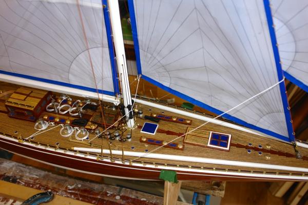
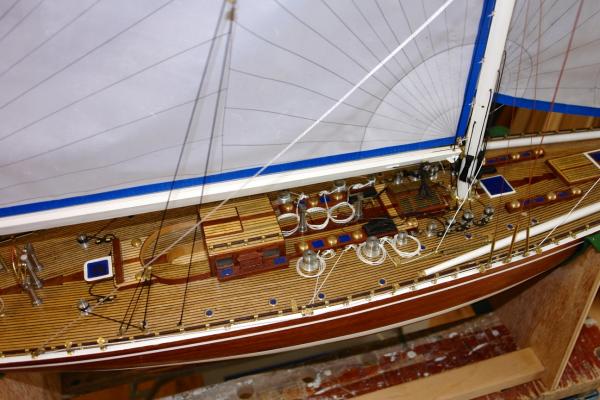
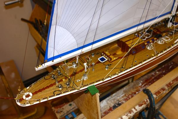
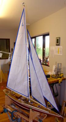
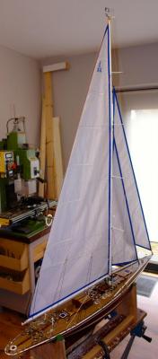
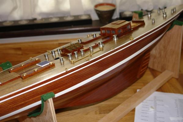
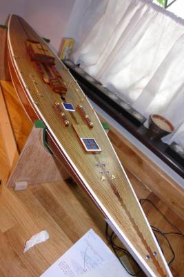
A final few photographs. I think I will also do some refections on the build in a future post plus some thoughts on my next project. I also have to make a display stand and possibly a display cabinet. I will cover these as and when I get round to making them. Keith


- 85 replies
-
- 12
-

-
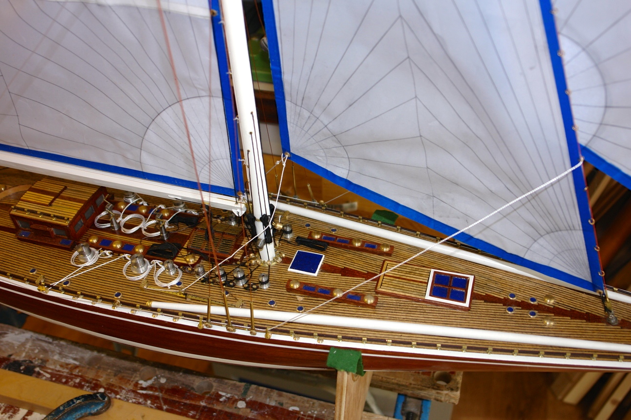
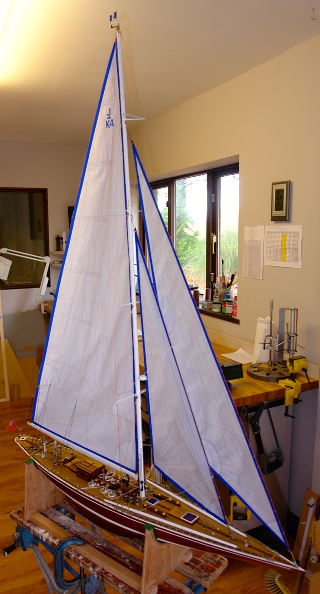
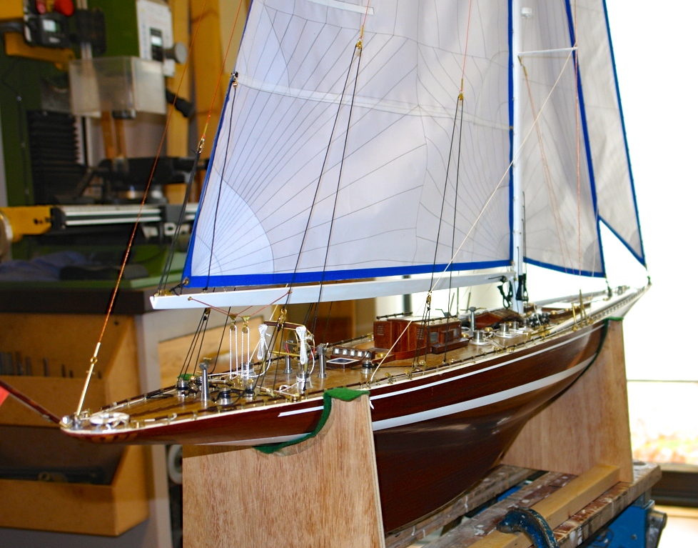
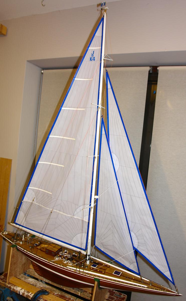
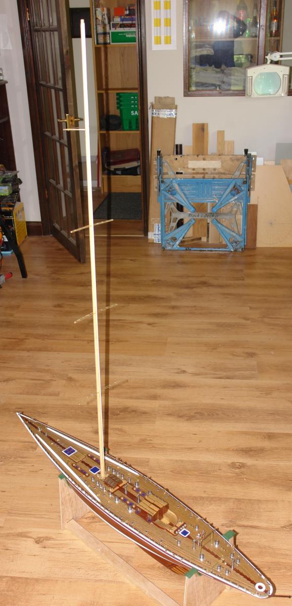
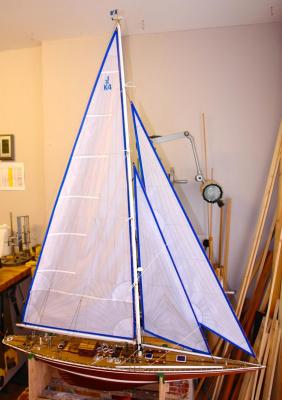
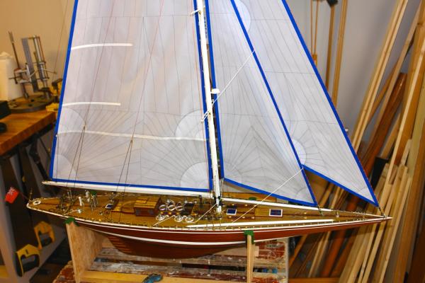
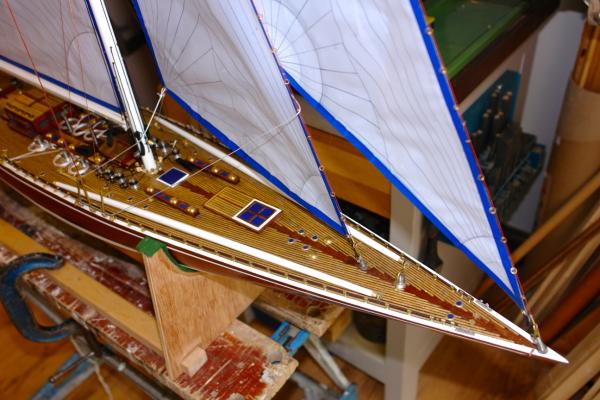
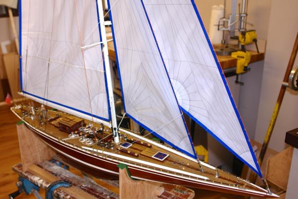
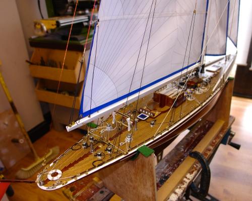
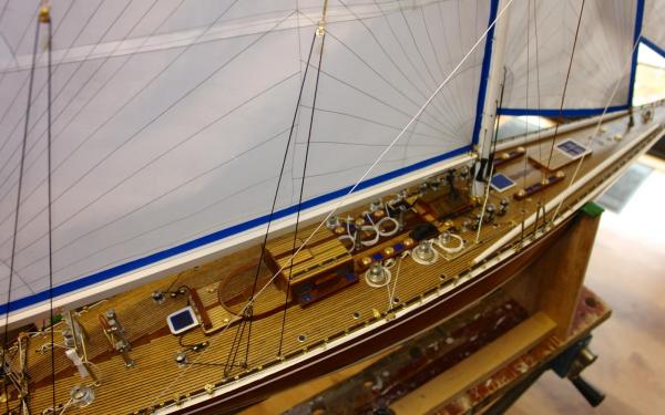
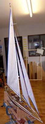
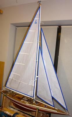
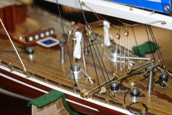
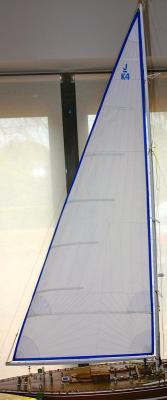
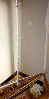
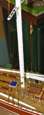
I have now finished - it took a bit if time to get the sheets and halliards tidy but a couple of simple jigs helped. Here are a selection of photos of the finished model. I will post a few more tomorrow.


- 85 replies
-
- 11
-
-
Julie You may have seen this. http://www.adamlaystudio.co.uk/wp-content/uploads/2014/05/Endeavour-Boat-International-July-2012.pdf Keith
-
Julie I don't think anything is unrealistic and on my next build I think I will try to simulate deck hatches. The teak edging to the seating area looks a bit tricky. I have steamed and bent hard woods in the past but I find very tight bends on anything other than veneer (.020") tends to lead to splintering. The up-stand for the well on my build was made out of 3 thicknesses of veneer, soaked in boiling water and then glued over a former turned to the correct diameter. I think if I wanted to duplicate the edge detail I'd form the outer profile in a thin plank of teak and then glue it over the well and then cut out the centre of the sheet to form the inner profile as a final operation, however I can think of a number of options. I experiment when I come across new situations and usually find something that works. Keith
-
Hello Julie Thank you for the comments. Much of your build will be the same as its only the deck detail that differs to any significant degree. You will find a couple of other Endeavour build logs at 1:35 and 1:80 scale which you might find useful particularly as these keep closely to the Amati 1934 original detail. I started my sailing in 1978 and still manage the odd week away. Prior knowledge did help, particularly with the rigging details. The downside is that I became a bit obsessive about knots, which all had to be correct even though they were too small to be seen in detail. I think you will find the kit a good entry point into ship modelling as it gives plenty of challenge while rewarding the modeller with reasonably rapid progress and pleasing results. My build took 10 months of about 10 - 15 hours a week but this included a lot of time searching for deck details. Your build should be less time consuming. Good luck with you build and may your time pass pleasurably. Keith
-
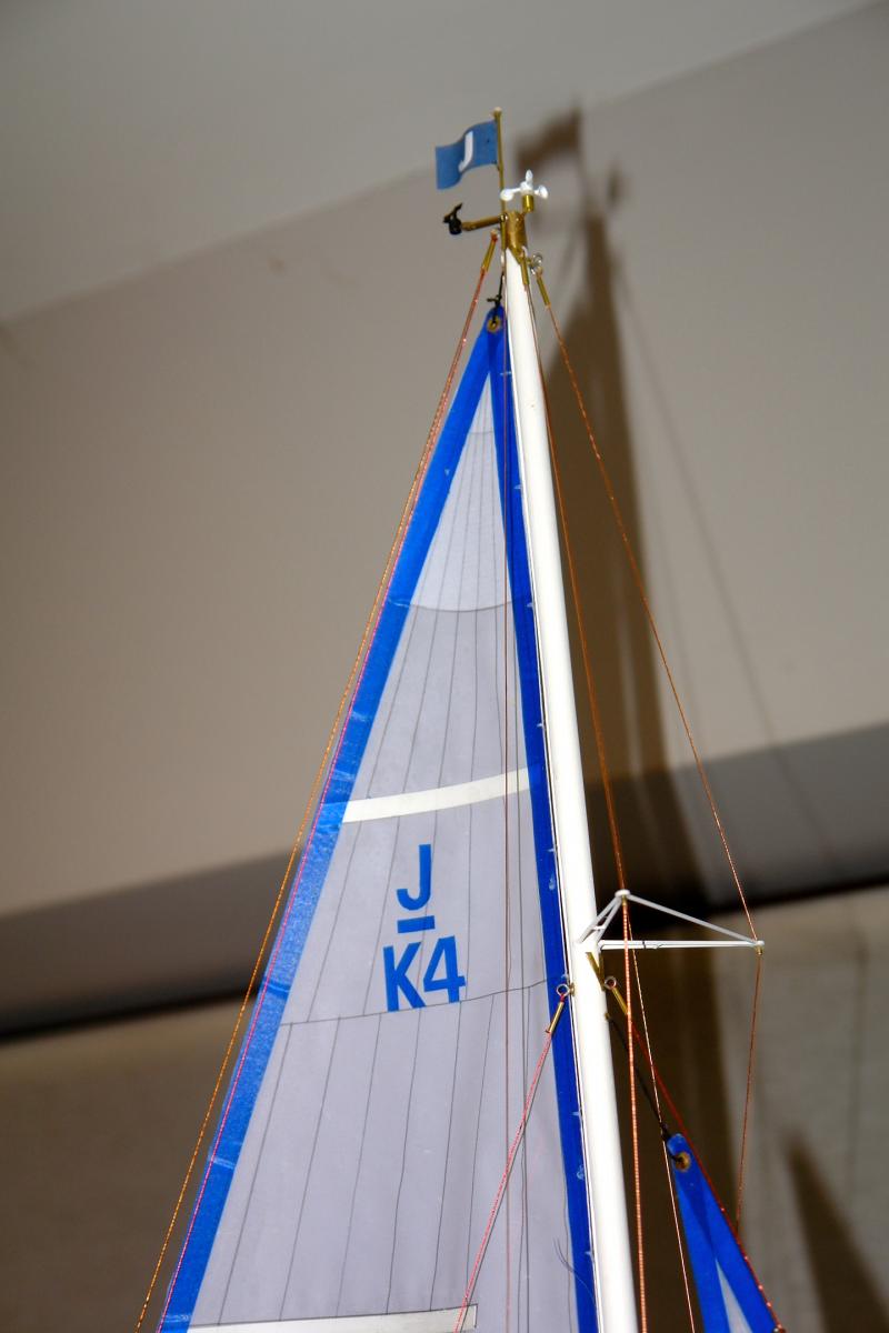
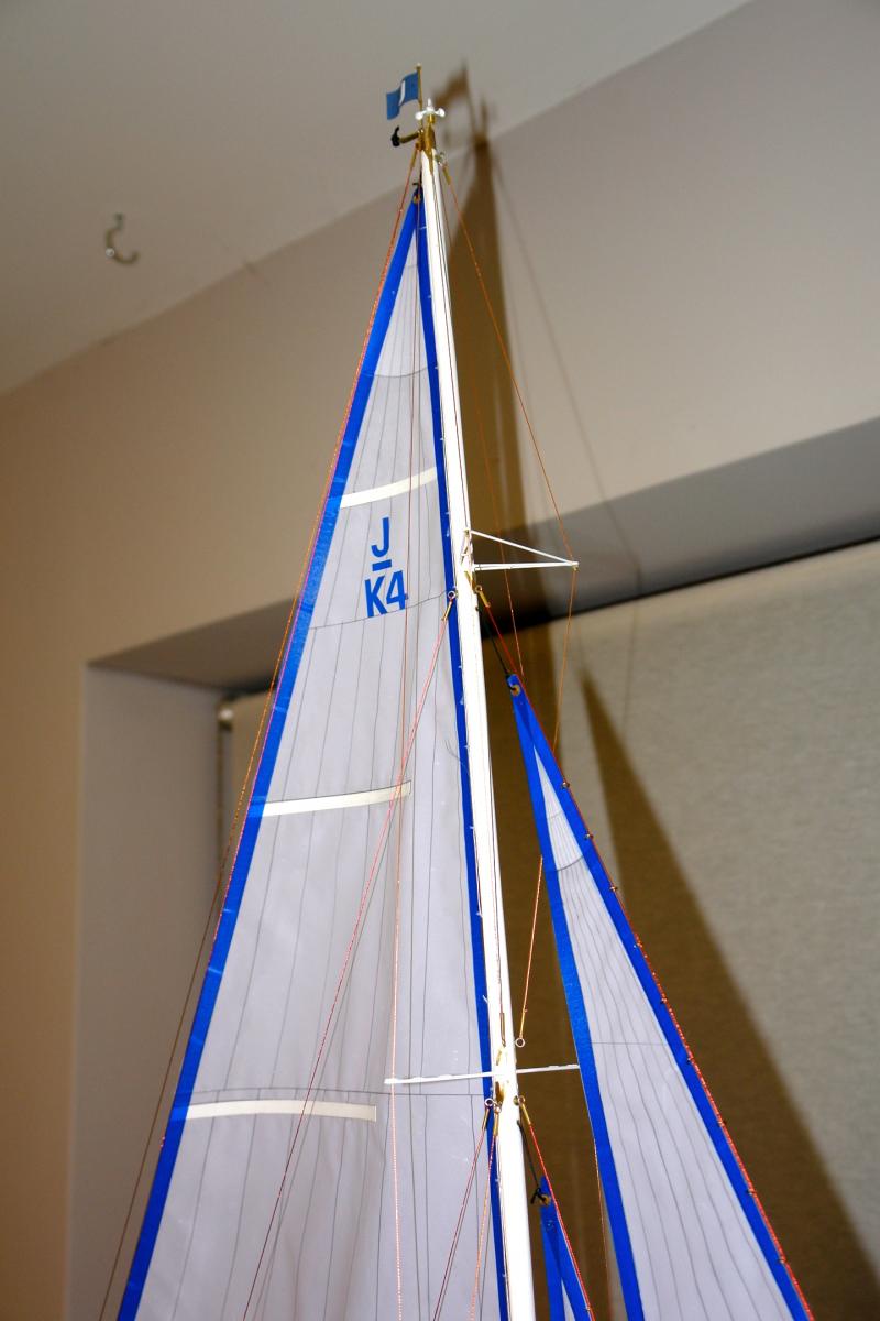
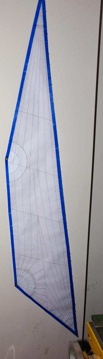
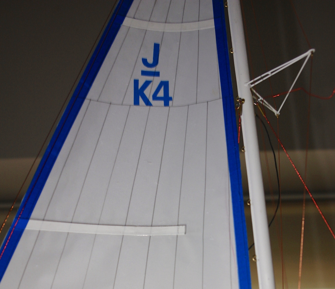
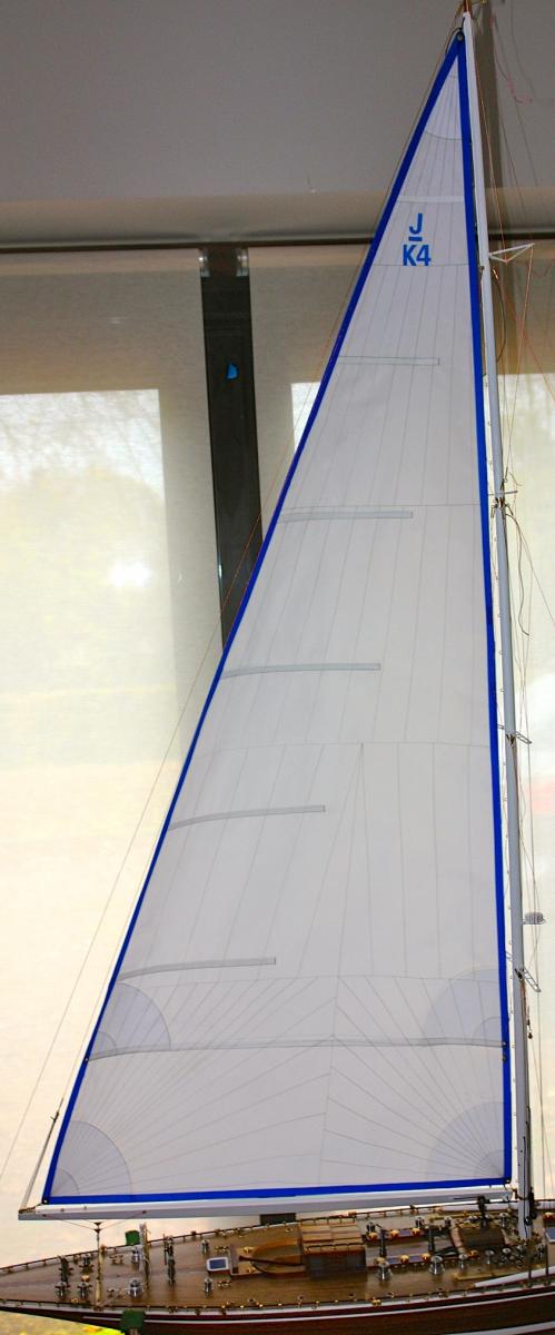
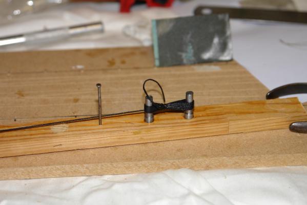
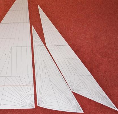
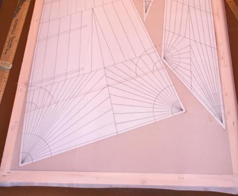
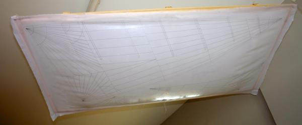
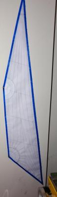
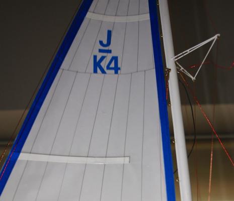
Sails A few considerations before starting: I realised that for the mainsail to look good the foot, luff and leach all needed to be fairly taught. This meant that the dimensions of the 3 edges of the sail had to be a little shorter that the corresponding measurement at the boom and the mast. Also the leach needed to be of a length that could be tensioned by the main sheets without the boom bottoming out on the deck mounted boom support. The jibs also needed to be sized to be tight on the leach and not so large that they fouled the shrouds. I decided to template the sails in plastic sheet ( left over from the template used to size a recently fitted kitchen worktop). As a guide I started by making the templates slightly larger than the sail plans supplied with the kit. I then offered them up to the model and marked and trimmed them until I was satisfied that they were ok. The modern sails of the 1989 Endeavour have a much more complex panel / reinforcing arrangement that the 1934 sails. I didn't think stitching was appropriate for creating this degree of detail and I was also concerned that stitching would lead to puckering and distortion of the sails. I marked the sail detail on the templates for later transfer to the sails. I created a frame to stretch the sail cloth over and mounted the templates on a board located temporarily within this frame . Having stretched the cloth I traced the sail detail on to the sail cloth I then used PVA glue diluted 1:1 with water which I applied to the cloth as a stiffener as suggested in the kit. It all went wrong at this stage. Despite the tension in the cloth the application of the fluid caused the cloth to sag considerably. I decided to make the best of a bad job and hung the frame from the workshop ceiling so that the cloth sagged uniformly. Fortunately some tension did reoccured during drying. Next time I think I will wet the cloth prior to the initial tensioning. After drying I applied additional thicknesses of sail material to simulate the reinforcing around the clews. I found the best way of simulating the sail batterns was to cut and superglue glue thin strips of plasticard directly on to the sails. Having cut out the sails I had a few experiments on binding the edges, most of which looked awful. I then remembered a roll of self adhesive sail repair tape that was languishing in my sailing gear bag - bought many years before in Jersey (Channel Islands). I cut this into 3/8 inch strips and this gave an acceptable edge detail. I used dressmakers eyelets to form the clews. I also cut the registration number J/K4 from the sail tape. I am now on the last lap and expect to finish the build over the next few days.


-
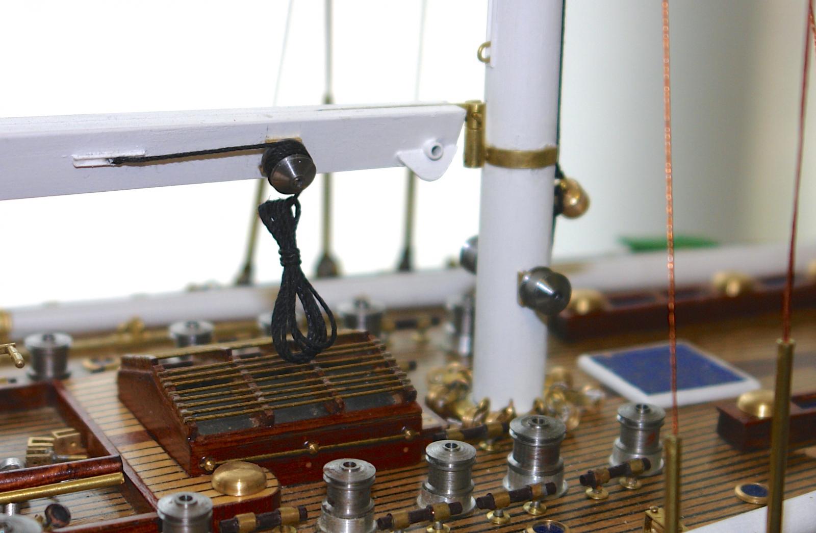
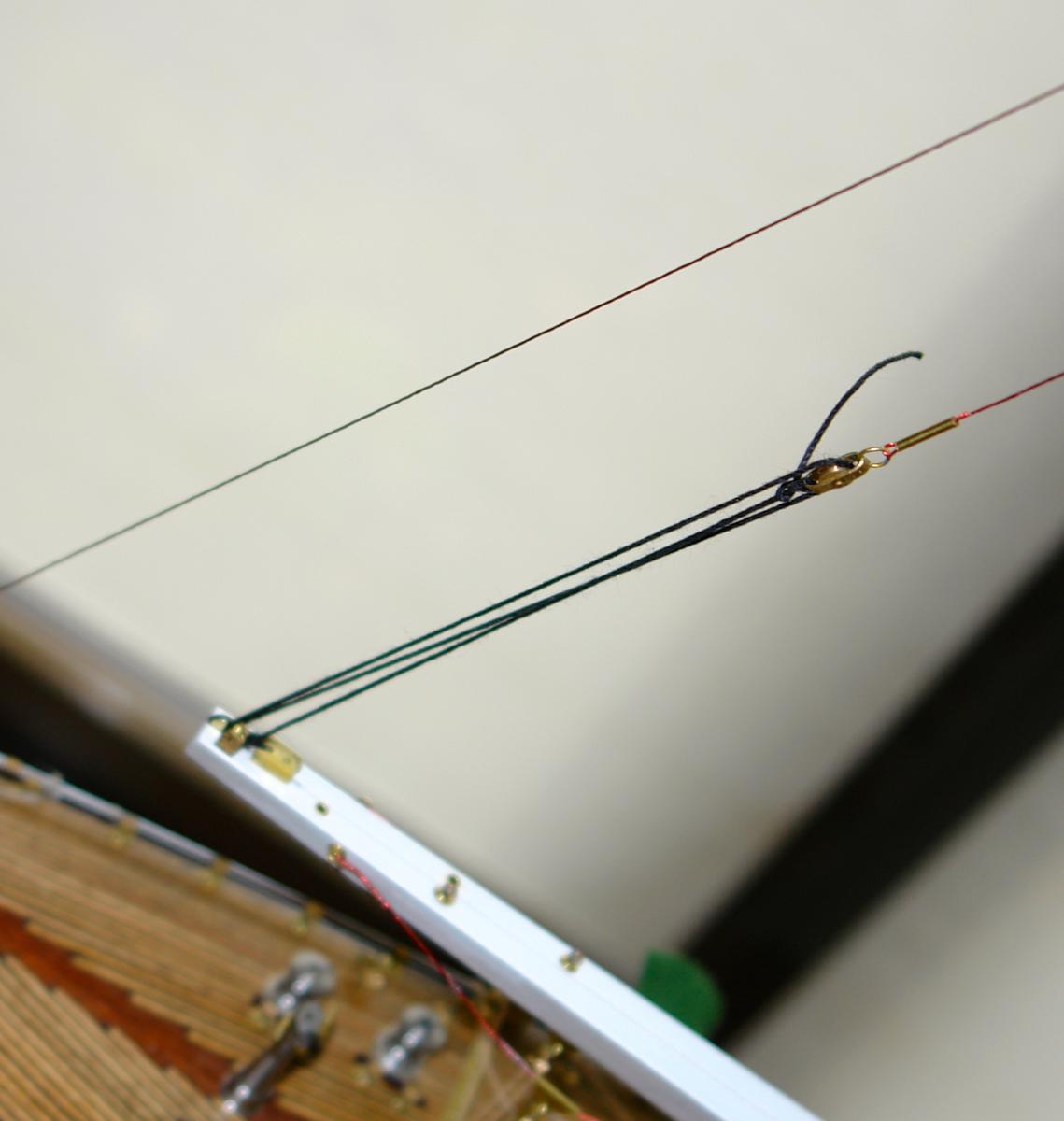
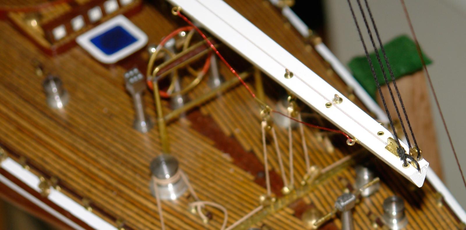
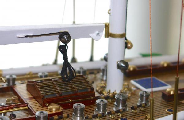
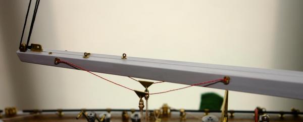
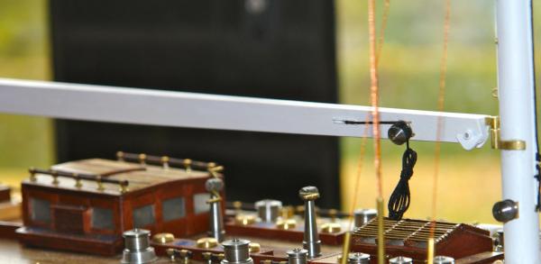
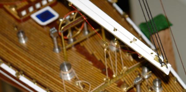
Main Boom (a short post this time) I really over thought this - working out various schemes for setting up the milling machine to taper the boom accurately. In the end I marked out the taper on the triangular wooden dowel provided in the kit and shaped it with a block plane - finishing with sand paper - simple is often better!!!!!. The hinge to the mast works in 2 planes (side to side and up and down). The topping lift configuration is copied from relevant photographs as are the fittings for attaching the main sheets and reefing points. Next i will cover sail making - something that I have not done before and something which I approached with a degree of trepidation. I have seen too many models with limp, ill fitting sails and I was concerned that getting something that looked ok was going to be beyond me.

-
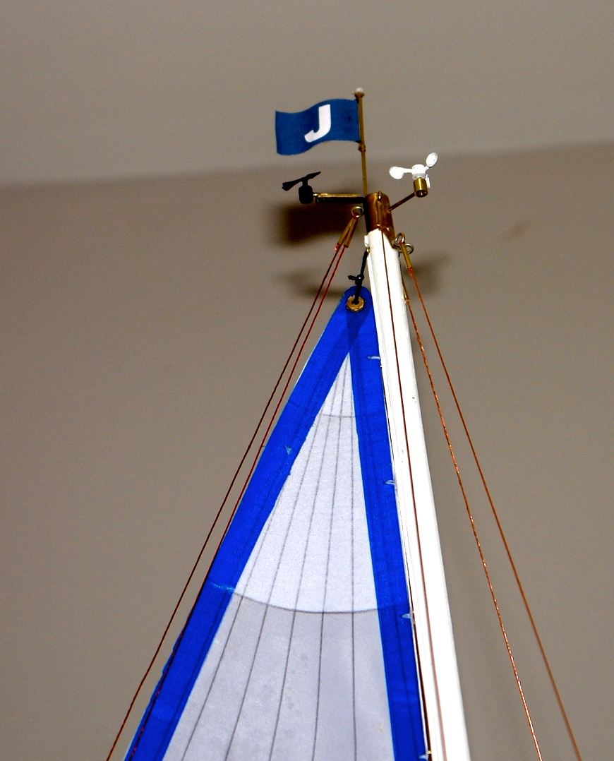
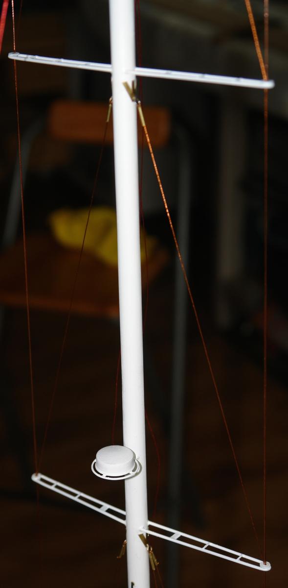
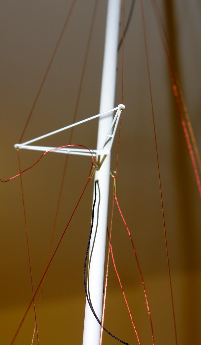
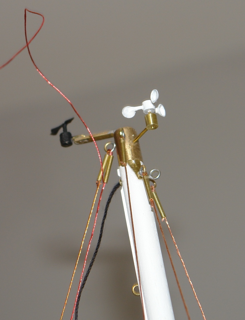
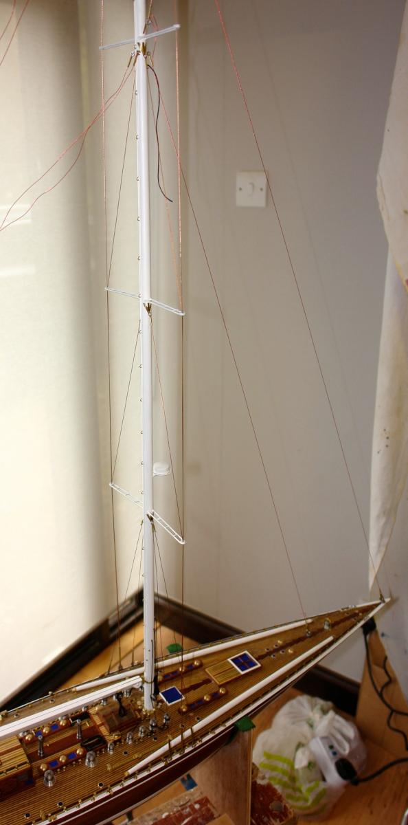
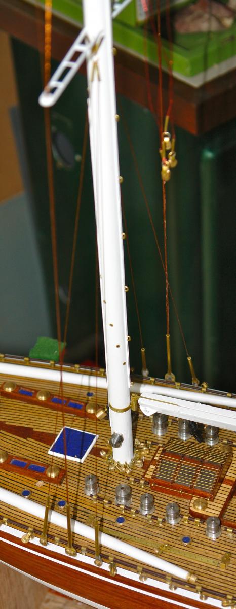
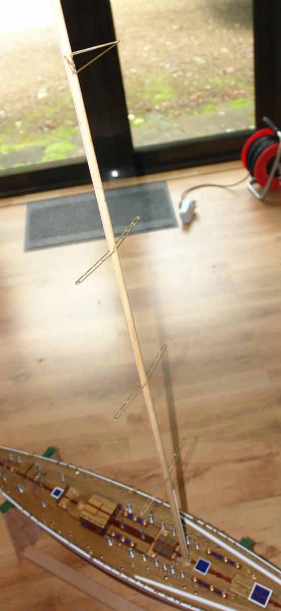
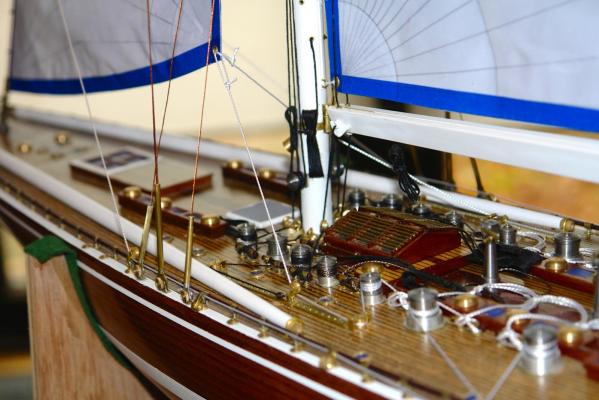
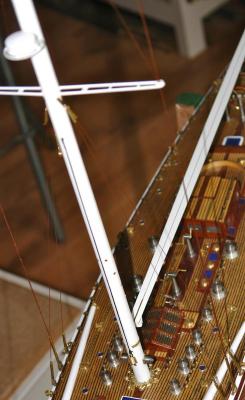
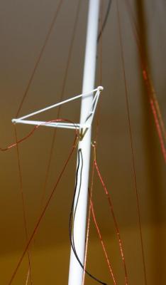
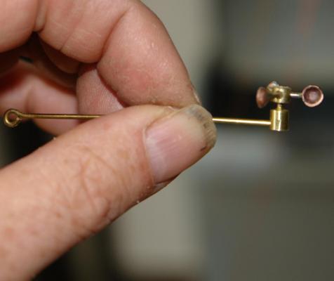
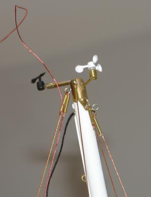
Thank you to all of you still prepared to follow and comment on my build. Following up earlier comments - it is correct that the 1989 Endeavour should not have a drop keel - unfortunately I hadn't made the decision on the version I was making at the time I installed the drop keel. As it is hidden from view when retracted I thought I'd leave it. As for the 1989 version having a motor - I offer the same excuse - although I agree this is more noticeable. I must do better on my next build. Finishing the mast:- I used the plastic channel section provided with the kit to simulate the mainsail track running up the back of the mast and for the spinnaker track. The main track runners are loops of brass wire. I turned a brass cap for the head of the mast onto which I soldered the extension which carries the wind direction indicator. The anemometer was made/ from brass wire and copper sheet. I made a die for the anemometer cups and pressed them from thin copper sheet which I annealed to prevent tearing during the pressing / punching operation. The reinforcing straps at the various mounting points for the shrouds and stays were cut from thin brass sheet. The radar was turned from dowel and mounted on a brass wire frame. The mast was sprayed matt white to finish. Shrouds and Stays:- I wanted to make sure that the shrouds and stays remained taught and therefore decided not to use the string provided with the kit. Instead I used very thin (.004") copper wire (recovered from an electric shaver). Each shroud / stay was made from 8 strands of wire which were twisted (circa 500 turns). The collars (brass tube) at the end of the shrouds were useful in that they allowed the wire to be tensioned, held and adjusted prior to gluing. The photos of shrouds show some untidy tails which were not glued until the sails were mounted.


-
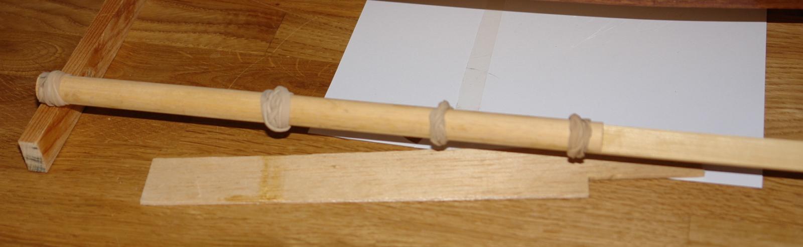
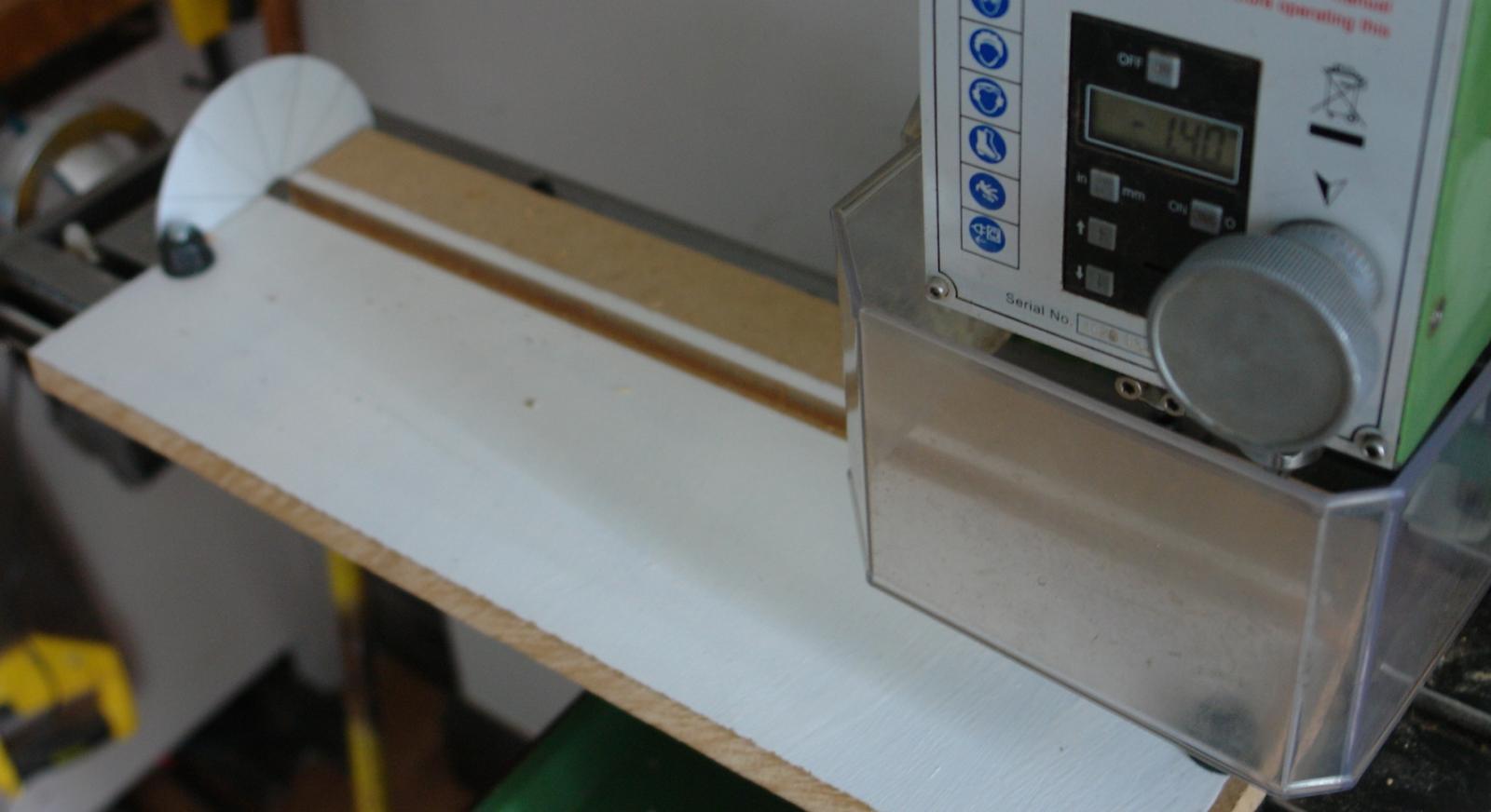
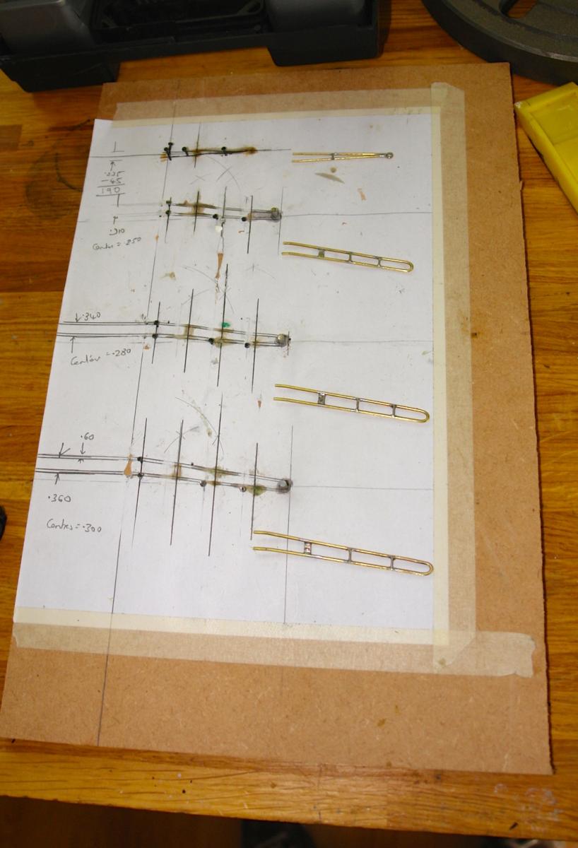
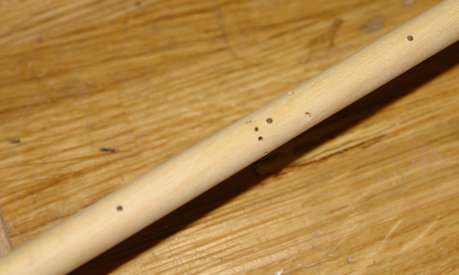
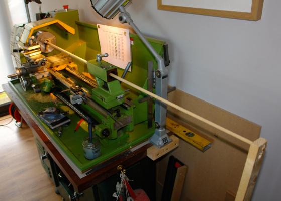
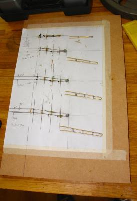
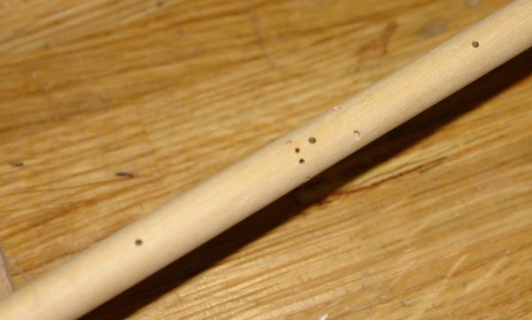
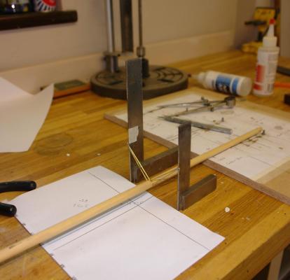
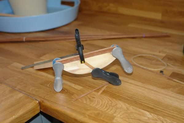
The Forming The Mast The kit provides a number of half round dowel sections which need to be glued together to form a composite round dowel of the right length - about 56 inches. I was a bit dubious and spent some time sorting through the shed to find a straight dowel of the correct length. Having failed I went back to the kit supplied material and glued them together as instructed. I held the assembly with elastic bands which worked well and the result was surprisingly good and straight. I wanted to get all the holes for cross trees, sail and shroud attachment points etc accurately positioned so I decided to drill them prior to tapering the mast. I cut a location slot in a sheet of MDF mounted in my milling machine and attached a "sighting card" over the slot so I could rotate the mast to the correct drilling angles. The slot allowed me to move the mast along its length while maintaining its position relative to the centre line of the mill. This worked well. I wanted to get the taper on the mast uniform along its length. The protrusion of the mast above the deck is 52 inches so I marked off 4 inch lengths and calculated the diameter of 13 cylinders from mast base to top. I then progressively turned the cylinders on the lathe. The diameter change between successive cylinders was circa .015 inches. The stepped cylinders were then lightly sanded in the lathe to remove the steps. I had to improvise with the lathe to accommodate the length and this involved stripping out the tailstock to use as a steady and supporting the overhang in a piece of wood mounted in my Black and Decker Workmate to prevent whipping. The cross trees for the 1989 version of Endeavour are somewhat more complex than featured in the Amati kit and to get them uniform I made a simple jig. The cross trees were made out of brass wire bent and soldered to form the correct shape. I was careful to get the correct angles when glueing the cross trees to the mast. I used quick drying epoxy to give me some time to fine tune the angles. And here is the mast part finished.


-
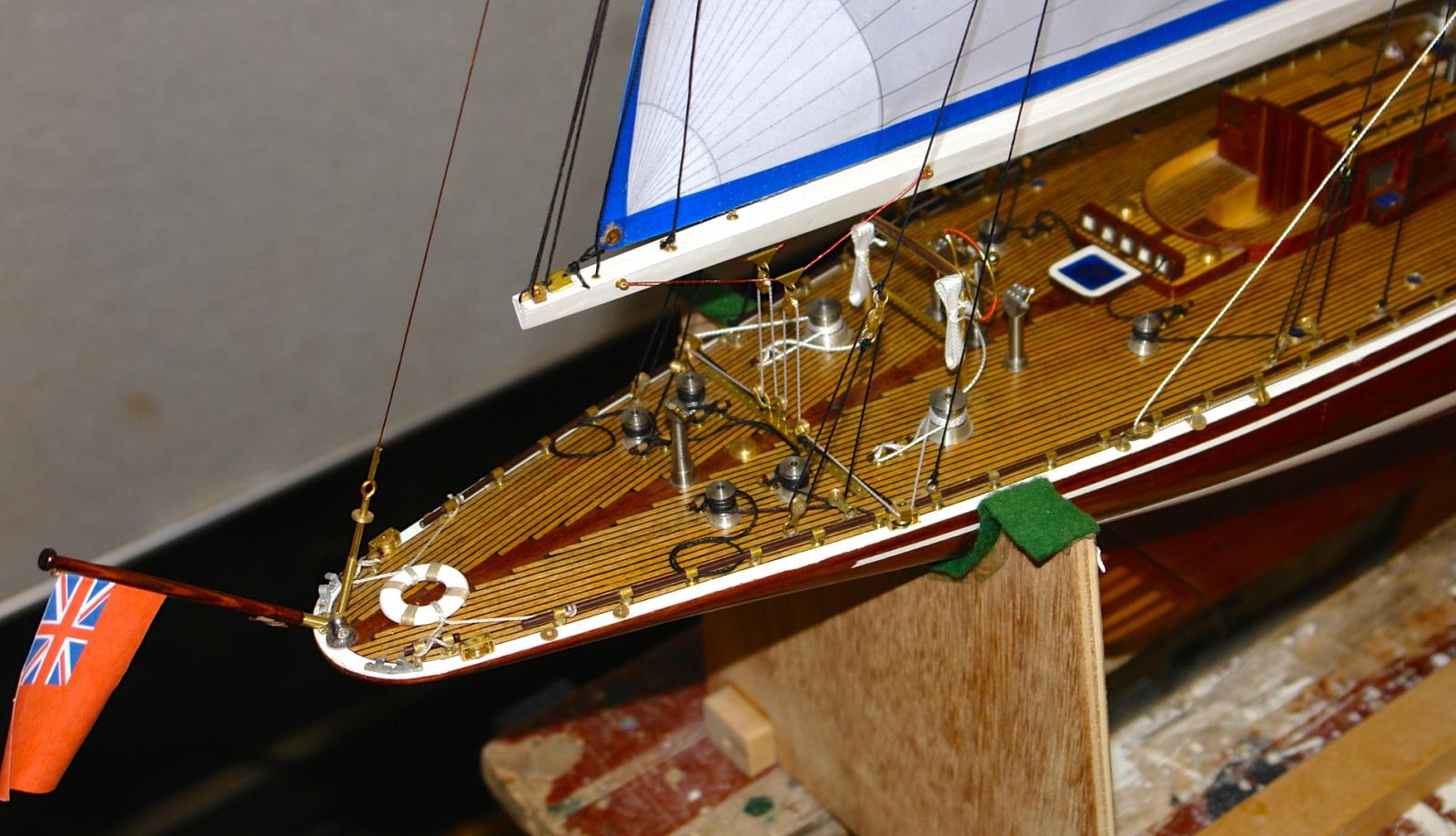
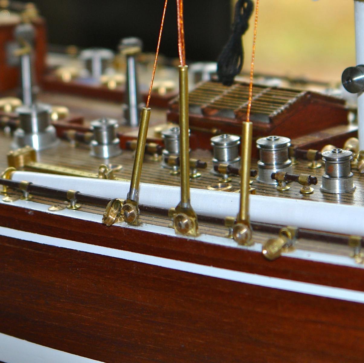
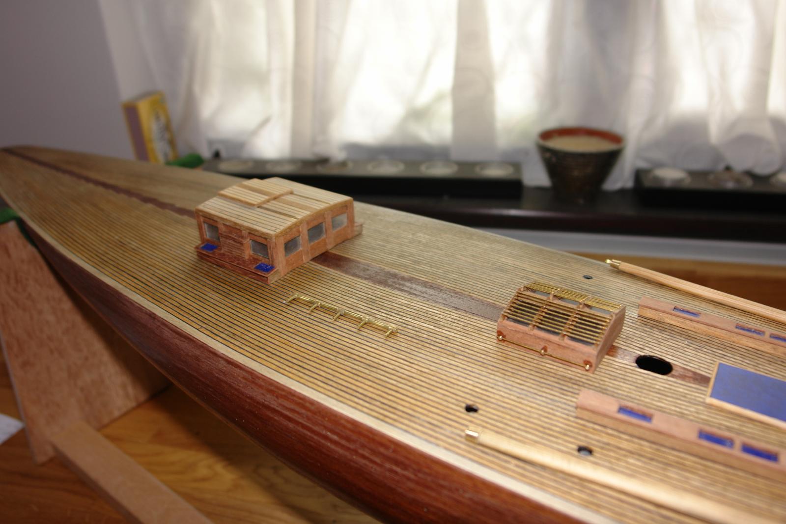
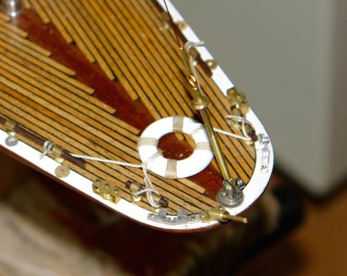
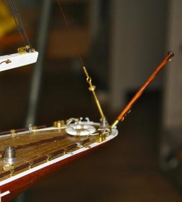
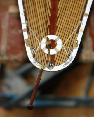
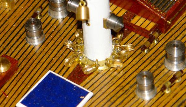
Before getting on to the mast and rigging I thought I'd post a few pictures of the final deck fittings. The spinnaker booms are made from dowel with brass end fittings. They were tapered in the lathe by sanding. The mooring cleats were cut from solid aluminium bar on the mill. The life ring was turned from ply sheet on the lathe and the ensign staff was turned from dowel. The pulleys at the base of the mast were a bit tricky.
-
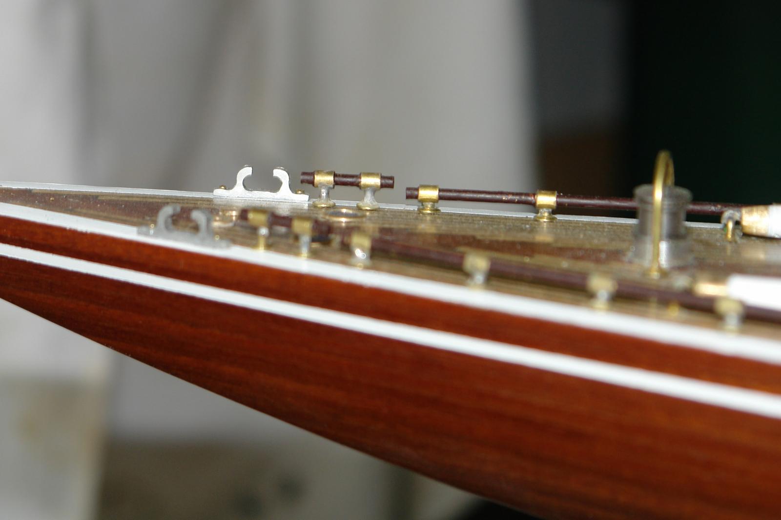
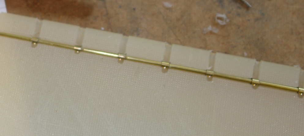
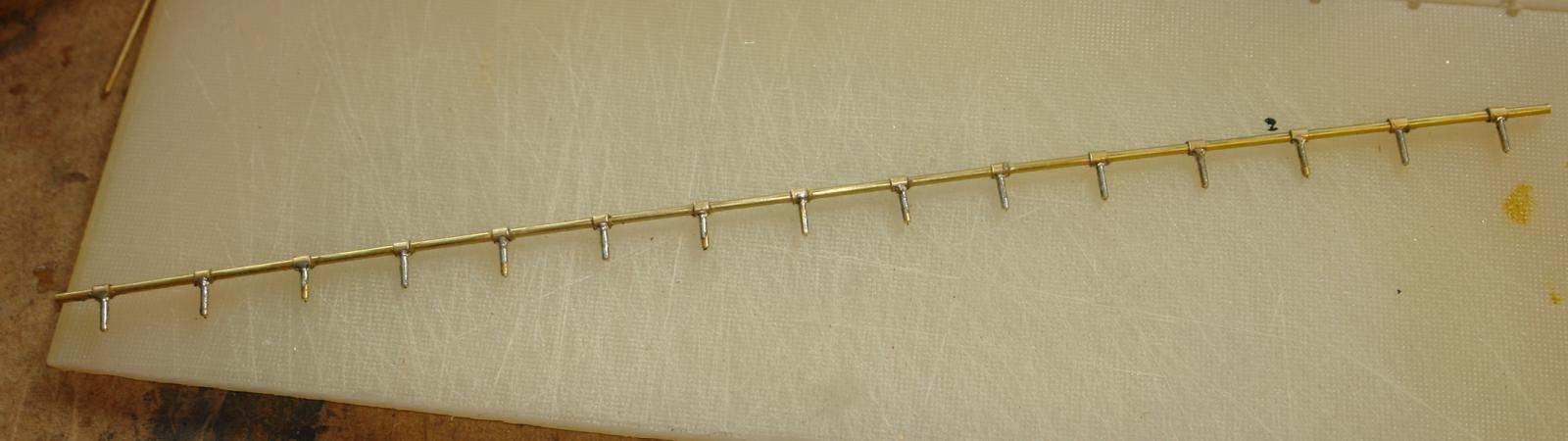
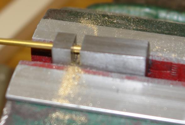
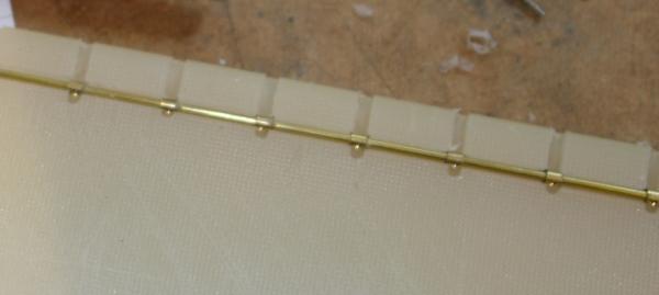
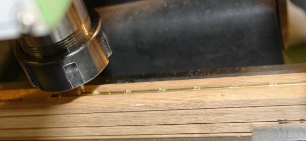
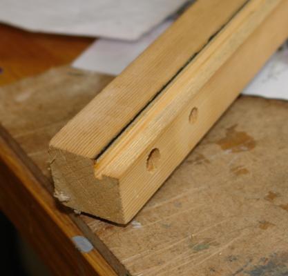
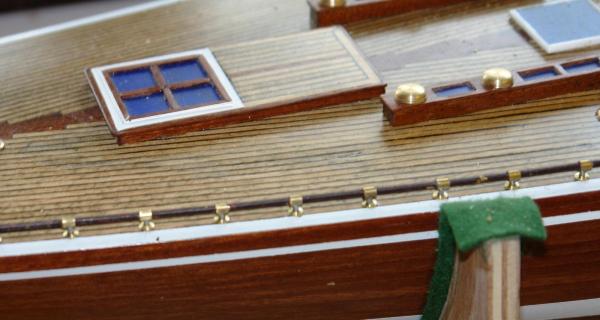
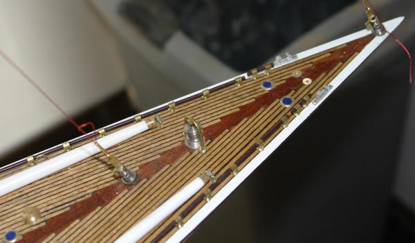
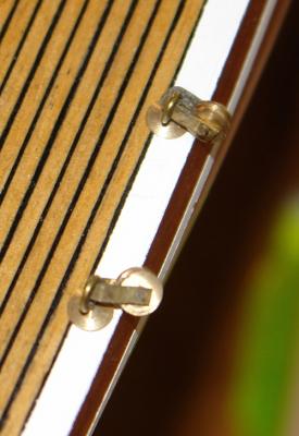
It has been some time since my last post so apologies to those following this build. Fortunately summer is long gone and I have returned to the build. For this post I thought i would concentrate on hand rails and cleats - both being similar in construction. I wanted the rails to be both robust and uniform. This led me to making the rails from nesting brass tubes and utilising simple jigs. The following photos show a series of jigs as follows:- Jig 1 - makes sure the rail fixing collars are all identical length - the collars are cut from tube which passes through the jig. The slot is the length of collar required - the tube being cut to length with a razor saw. Jig 2 - is made by milling grooves in a nylon cutting board - it positions the collars on the tube which forms the hand rail. The collars are held in place by super glue. Jig 3 - is a slot cut in hard wood which locates the assembled rail and collars for drilling in the milling machine prior to attaching the mounting pin. Jig 4 is a guide for soldering in the mounting pin. And here is one of the rails assembled. That of course is the interesting bit - the hand rails and cleats combined consist of over 600 individual parts which was somewhat tedious. Here are a few photos of the result. the brass rails have been painted to simulate wood. I'll be covering other bits of deck furniture in my next post within the next few days. Regards Keith


-
Yves I did drill holes for the first 6 (the ones at the bow end) but I then tried 1 without and decided they looked identical so didn't bother with the remaining 18. Keith.
-
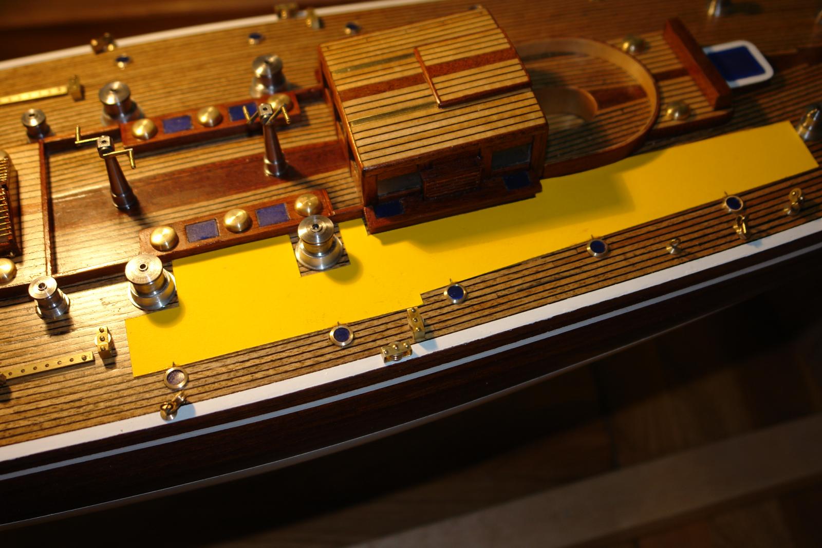
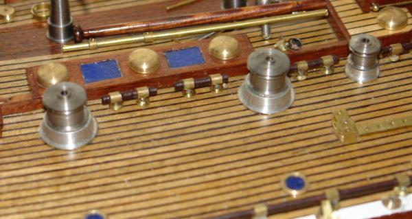
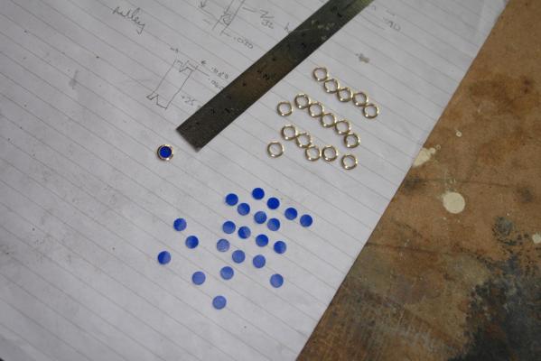
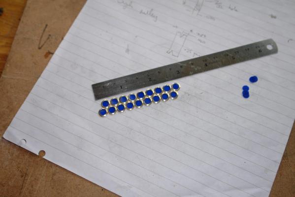
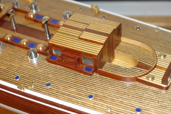
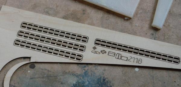
Deck port holes. My last post for several weeks - annual holiday. The kit features 6 deck port holes however the 1989 rebuild features no fewer than 24. A lathe production run was therefore required. A brass bar was turned down to the required outside diameter and then drilled out to the correct window size. I ground a turning tool to have the correct bevel angle on the leading edge - and this allowed me to complete forming and parting off in a single action. I initially cut teeth in the end of a tube to make a hollow drill which I used to cut the circular windows out of blue plastic sheet. I then realised that a hole punch produced the required diameters much more easily and I reverted to this form of manufacture. Positioning / glueing the port to the deck was assisted by the use of a template cut from card. The card was marked with correct port hole positions and then used to glue one side before being flipped to the other side. Goodbye for now. Keith

-
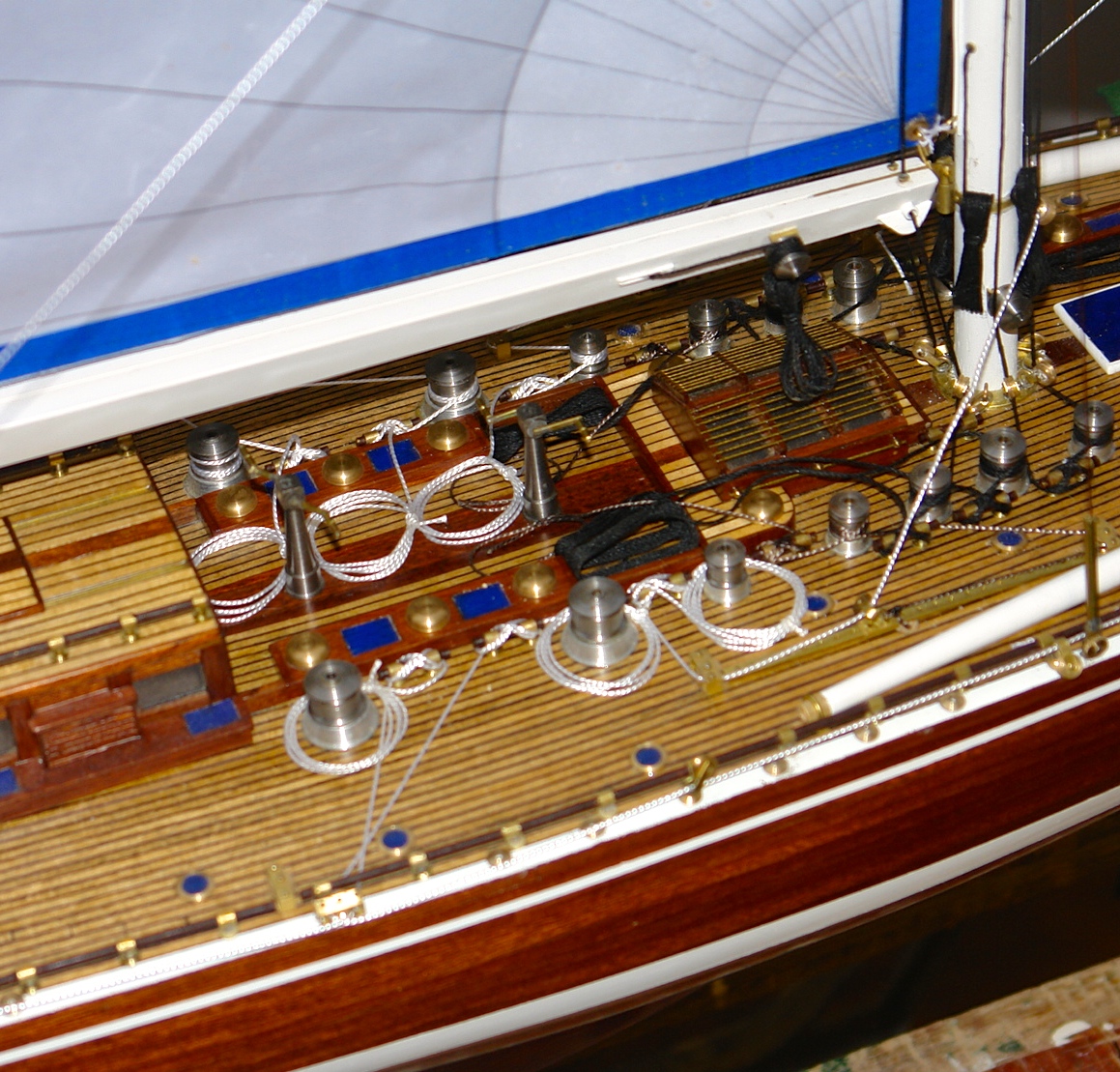
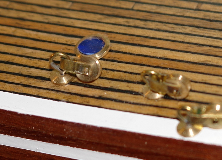
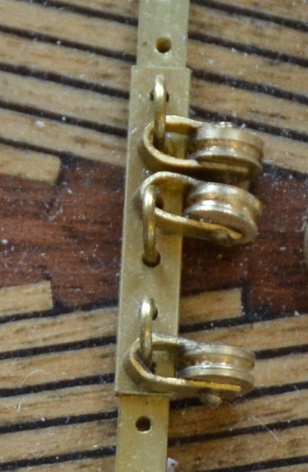
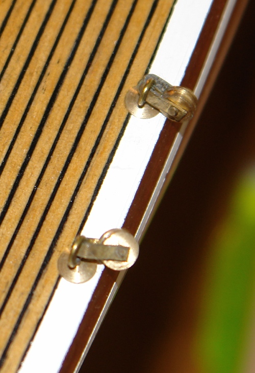
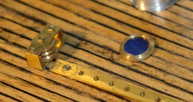
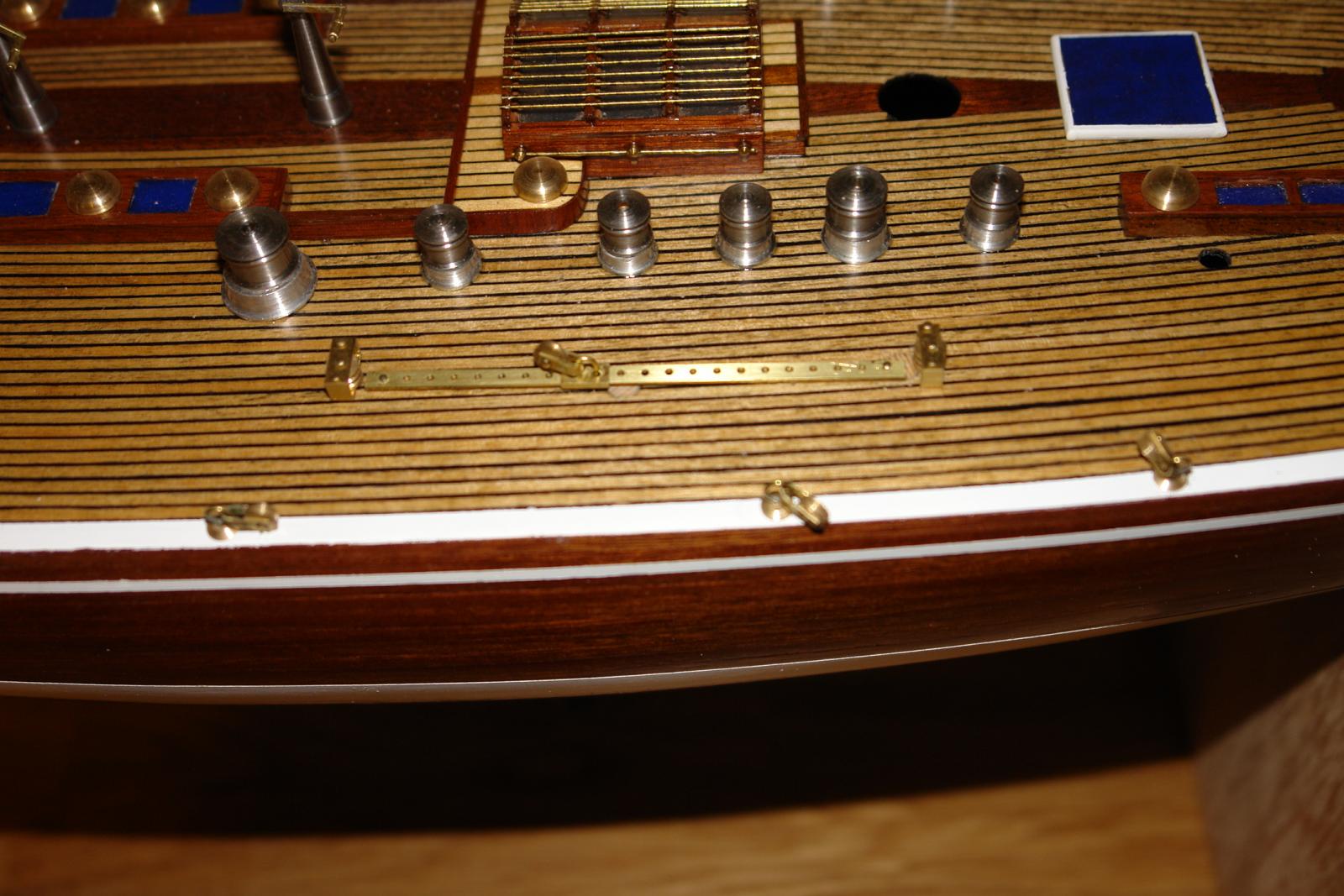
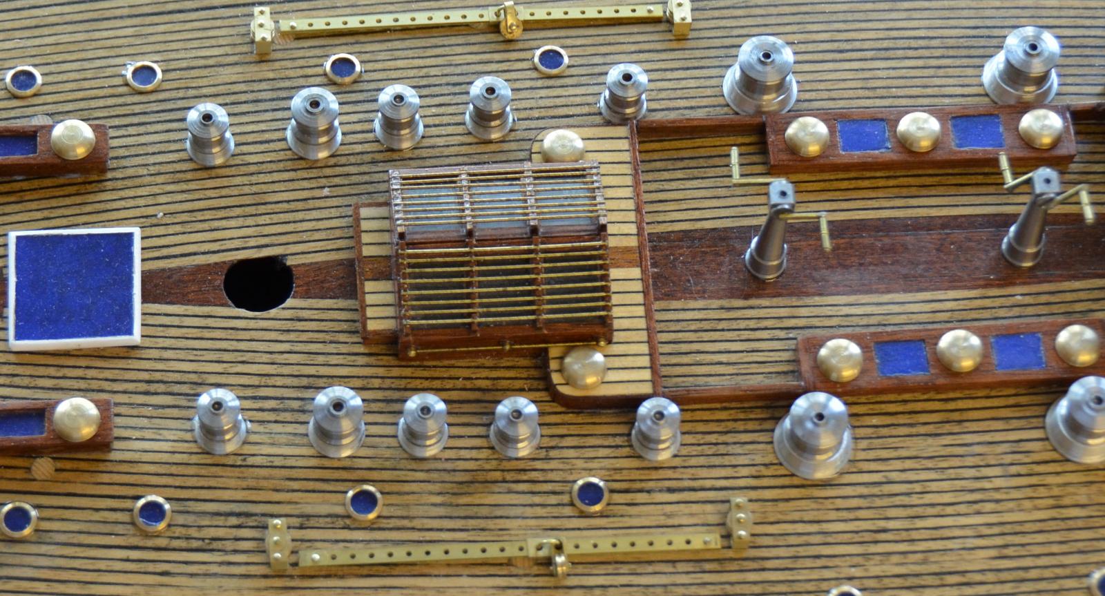
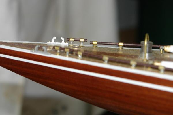
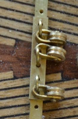
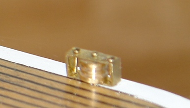
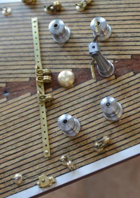
Tracks and pulleys The tracks were machined from a scrap piece of brass sheet 1.5mm (.060") thick. The holes were drilled first before 3mm (.120") slots were milled either side of the holes. The tracks were then parted off along the centre line of the slots using a 0.5mm (.020") slitting saw. This produced the "T" profile required for the 3 tracks. The Amati kit generally features blocks rather then the pulleys used in the 1989 refurbishment. The pulleys were turned from brass bar and mounted in frames made from bent sheet which was formed and then drilled to take the spindles. The deck attachment was made from wire threaded through a turned disc. The twinned pulleys are mounted in square hollow section brass tube.


-
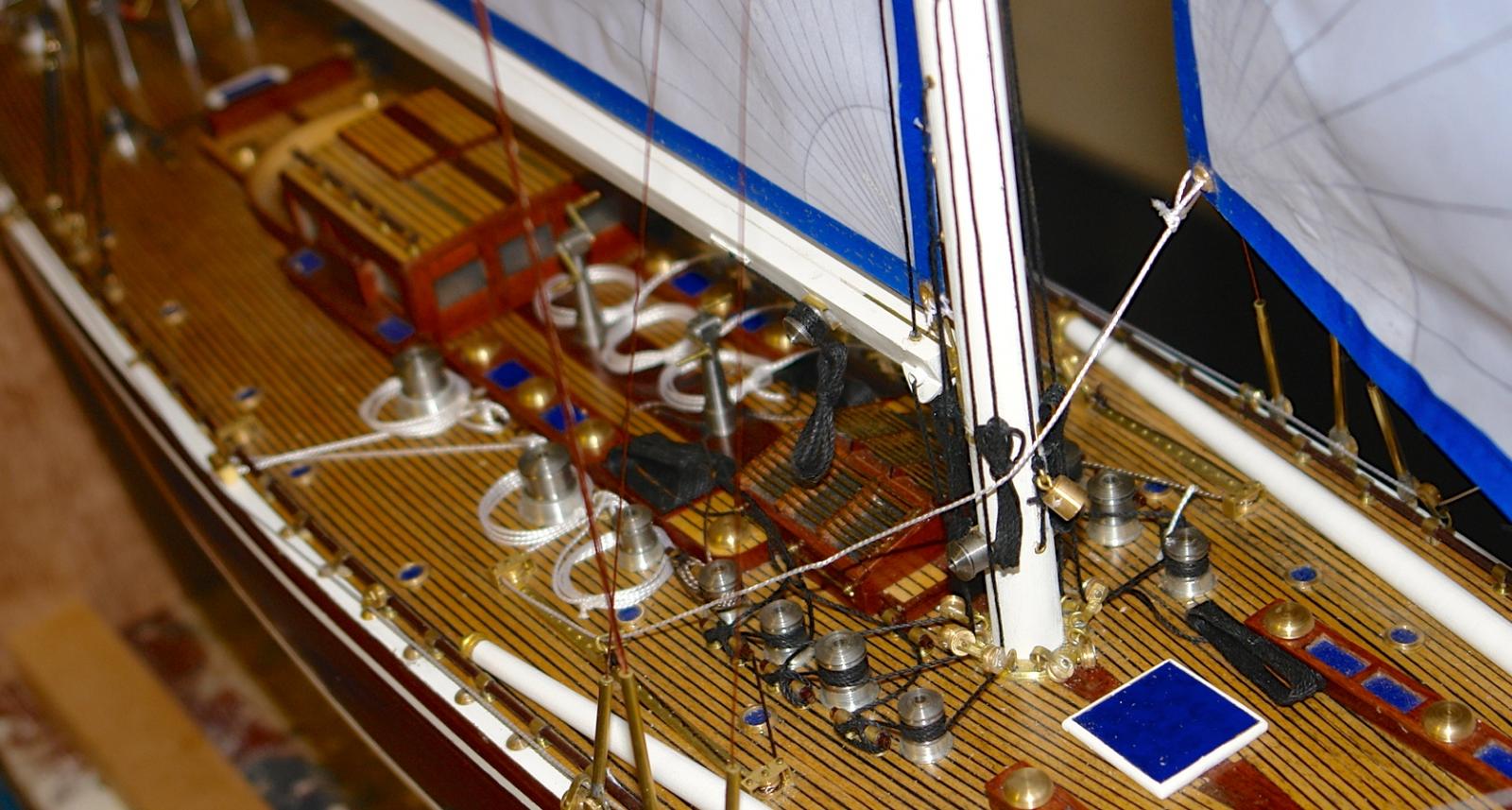
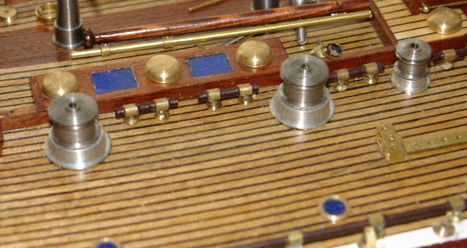
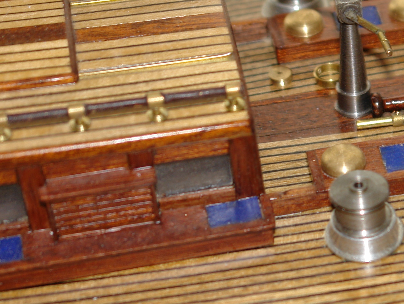
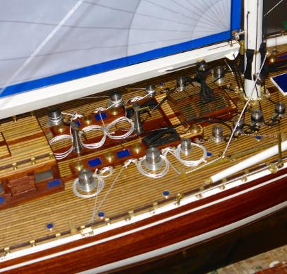
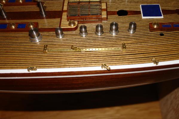
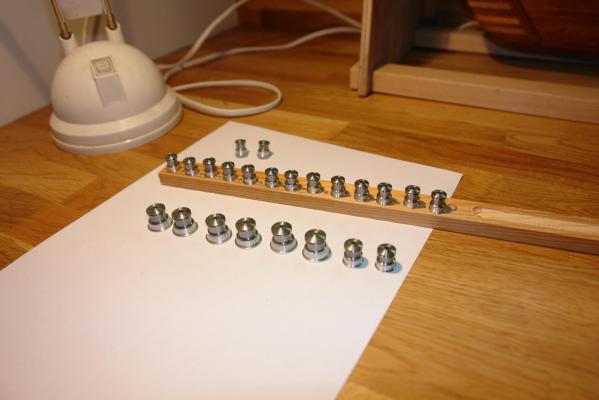
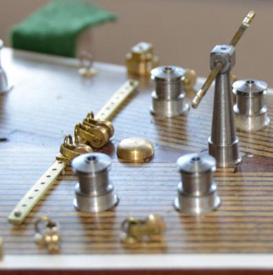
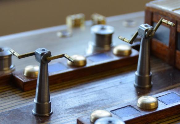
Winches and grinders Hi Jeff - my advice is "never burn your boats"! The Amati kit includes 9 winces and the picture on the box shows these correctly installed with 2 arms extending from the base. These arms allow the winch to be cranked by 2 crew members employing a rowing action. The 1989 rebuild features no fewer than 23 winches which are geared to the the 3 grinders. 6 large winches are for jib and main sheets while the remaining winches (in 2 sizes) are for track adjustments, halliards etc. I made the winches in 2 parts - the bases being turned from aluminium and the winches themselves being made from stainless steel. Three grinders are mounted along the centre line, 2 forward of the cabin and one towards the stern. The column of the grinders was made in 2 parts - the turned stem and turned / milled top. The handles are fabricated from brass strip, wire and tube.

-
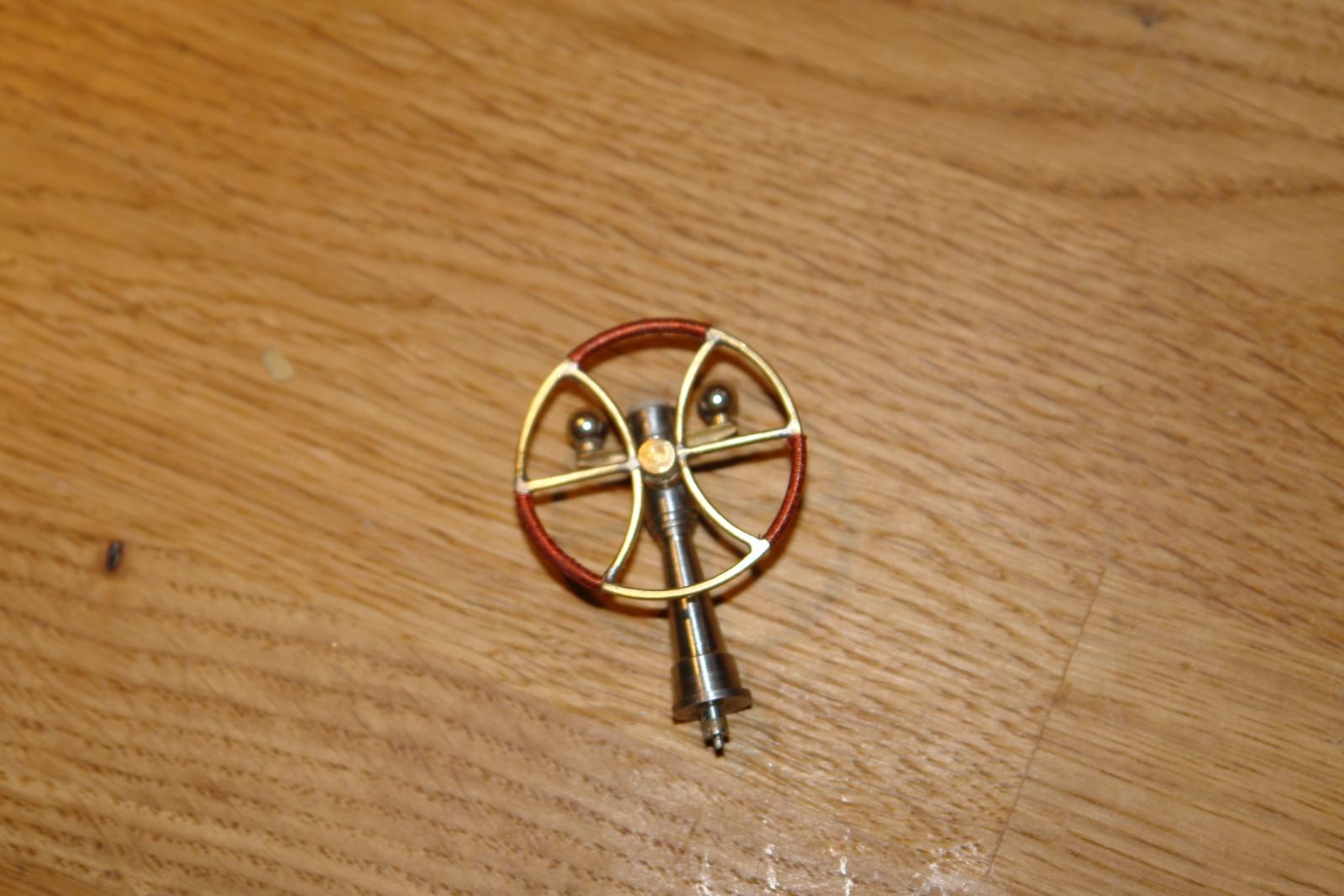
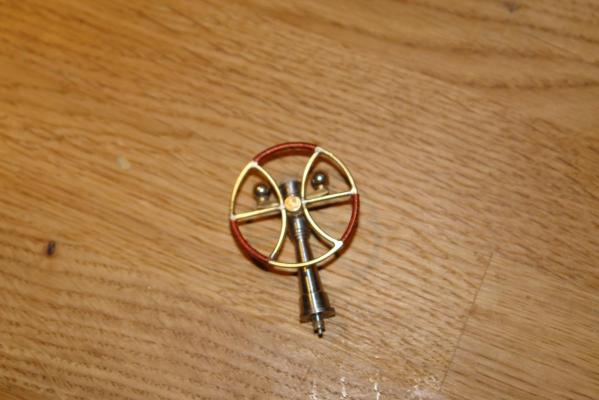
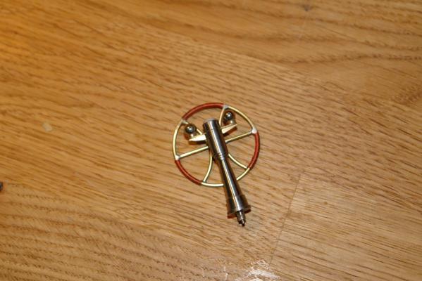
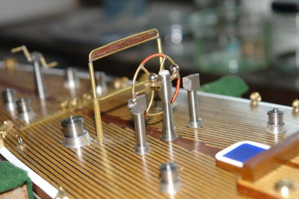
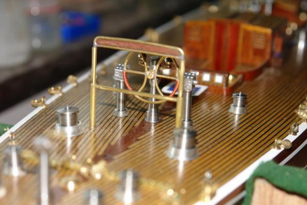
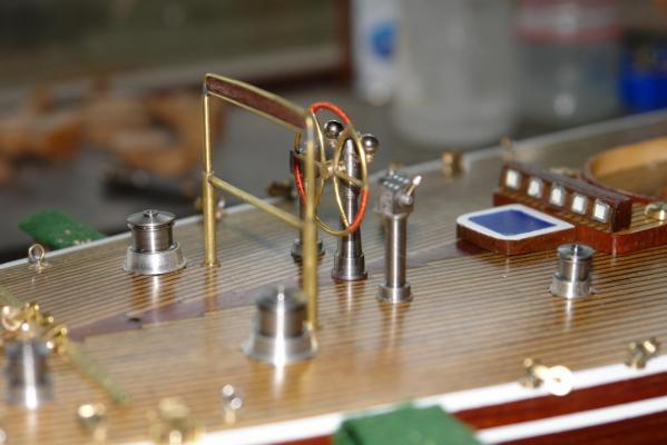
Having decided to model the 1989 rebuild of Endeavour I had to obtain details of the deck layout. Without plans I had to rely heavily on photographs. This was complicated because Endeavour was again refurbished in 2010 / 11 and in this later version she was considerably changed. I found a number of useful web sites which in combination gave a good coverage of the deck. Scaling sizes was a little difficult and I had to make do with guestimates which, while less than perfect, gave a passable representation of the real thing. I did eventually find a 150mm (6") long deck plan and this was of considerable help. I will happily provide the links to anyone interested. I did cheat with on one item - the wheel. In the 1989 version the wheel is a conventional stainless steel multi spoke affair. In the 2010 rebuild Endeavour was given a bespoke design of wheel which featured the "E" for Endeavour as part of the design. I couldn't resist this later version. I made the wheel out of 1mm (.040") wire wound round a wooden hub of about 80% the diameter of the final wheel, the spring in the wire causes the rim to expand to the correct diameter. Winding 2 hoops gave the required additional pieces for the spokes. The spokes and rim were soft soldered together and segments of the rim were wound with very fine copper wire to represent the binding. The column is turned from stainless steel (handles form a recently removed kitchen) and the balls are ball bearings. Two control columns sit either side of the wheel. they are arrayed with various buttons, throttle lever etc. They are made from 2 major pieces - turned columns and milled tops. I'll work through more of the deck fittings in later posts.
-
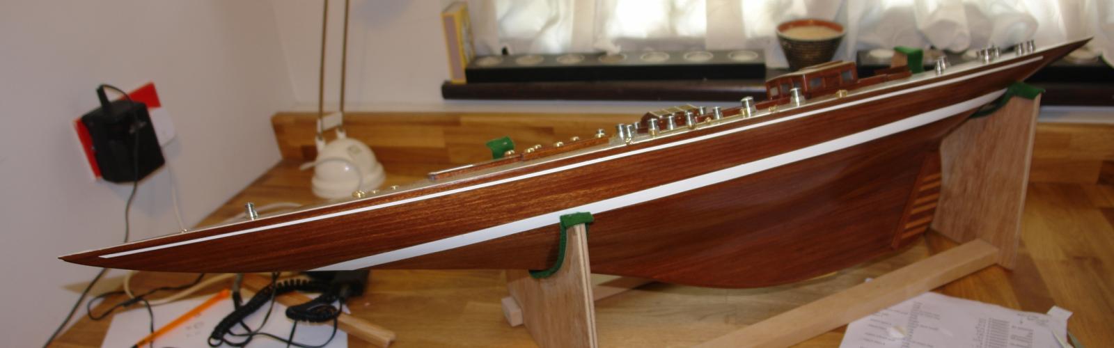
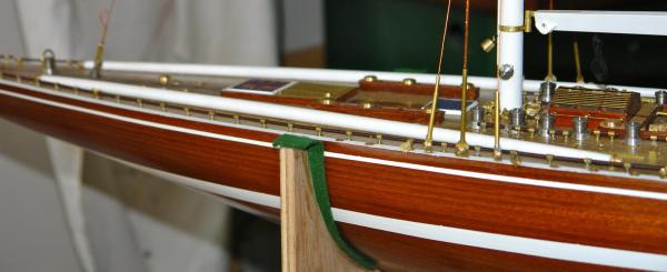
Finishing the hull. A very short post this time. Having completed the deck planking i gave it 4 coats of varnish. I wanted to keep paintwork to a minimum so decided that I would only paint the broad waterline band, a hull stripe and the deck edge plank. I decided to paint all in white using Humbrol enamel paint. I masked the hull for the waterline band using Tamiya low tack tape and painted it with an airbrush. I made sure the tape edges were well pressed down to eliminate bleed. Marking the position of the masking tape was done as per the kit instructions. The hull stripe was marked parallel with the deck using a folded piece of card (held against the deck and hull) to make sure that the distance to the deck was consistent. Two strips of tape were applied with a gap between, which was then hand painted. The deck edge plank was masked along the outer caulking line on the deck planks and at the top level of the hull. The masked deck edge plank was then hand painted. I didn't take many photographs at this stage but the attached photographs, which were taken later in the build, give some idea of the finish achieved.

-
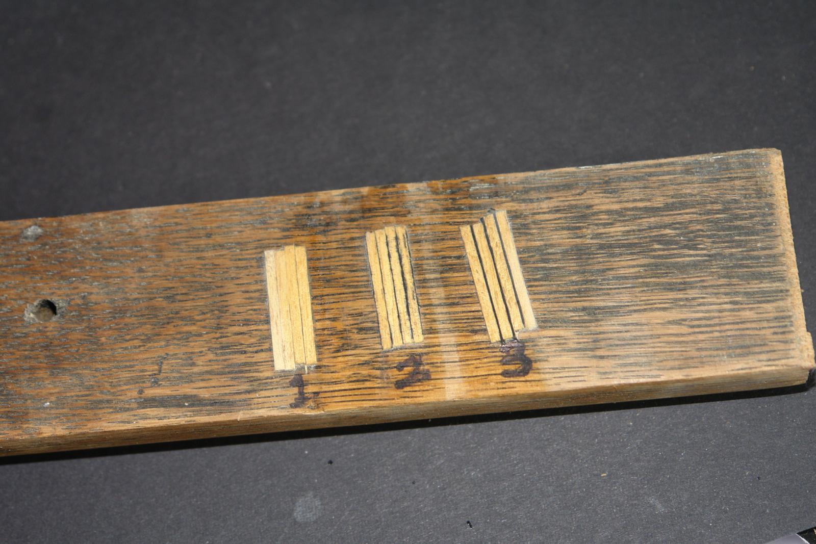
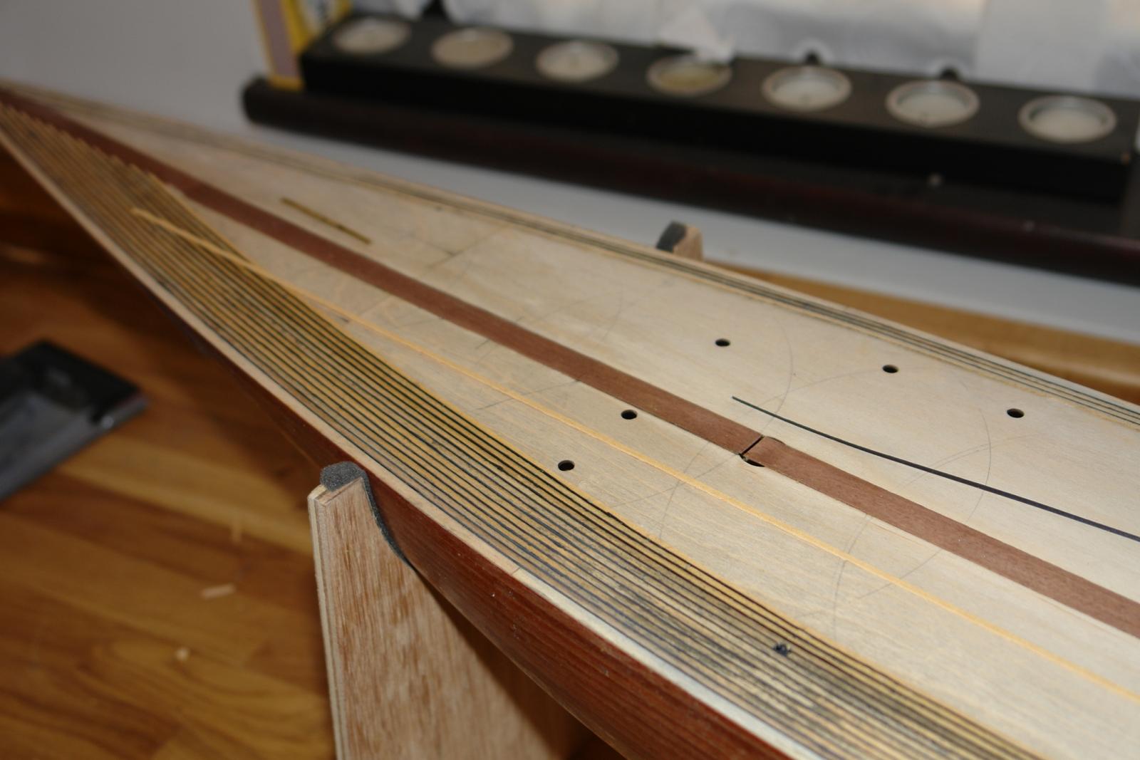
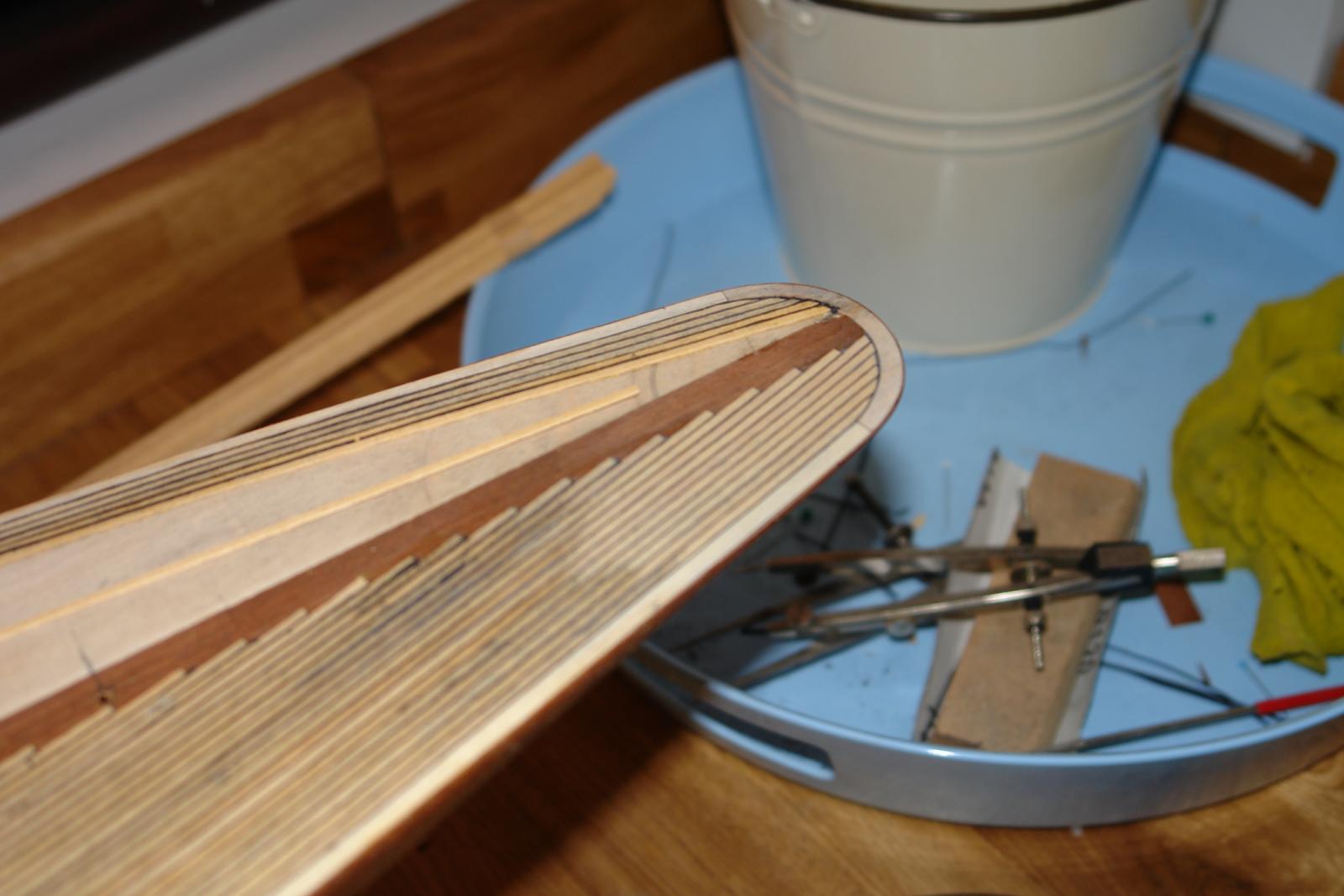
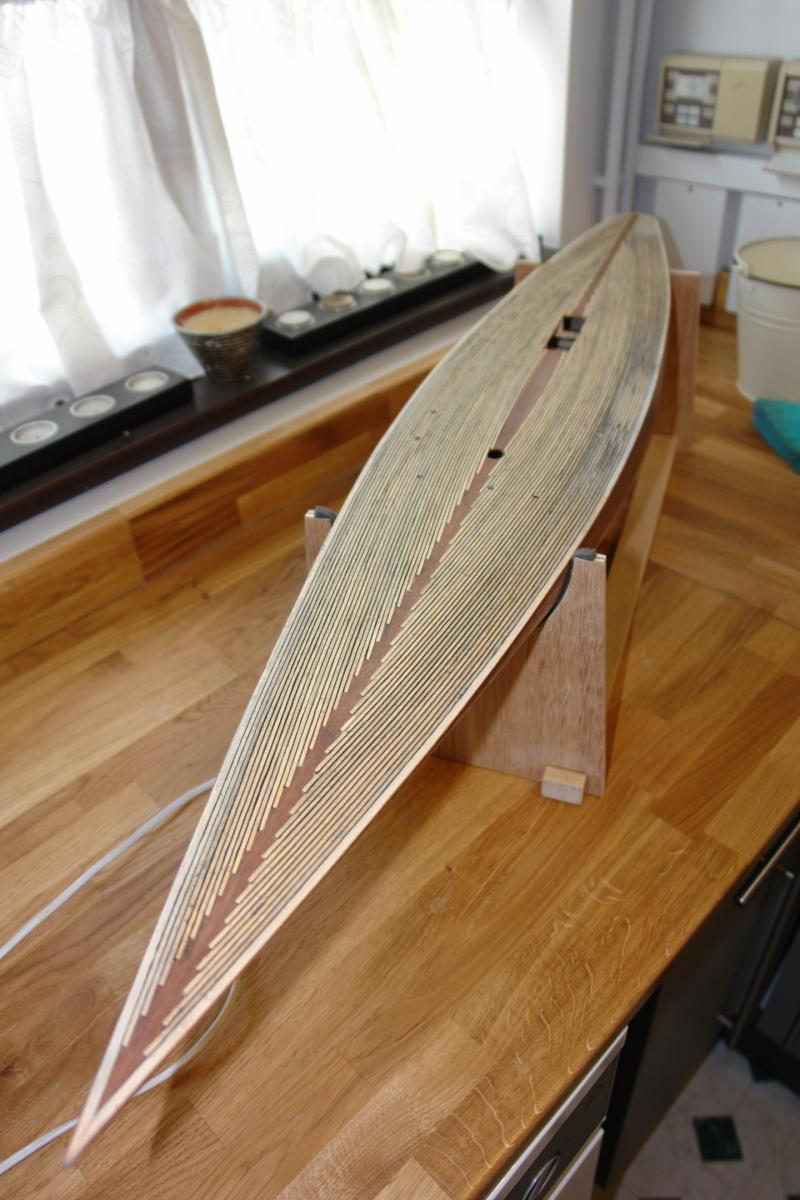
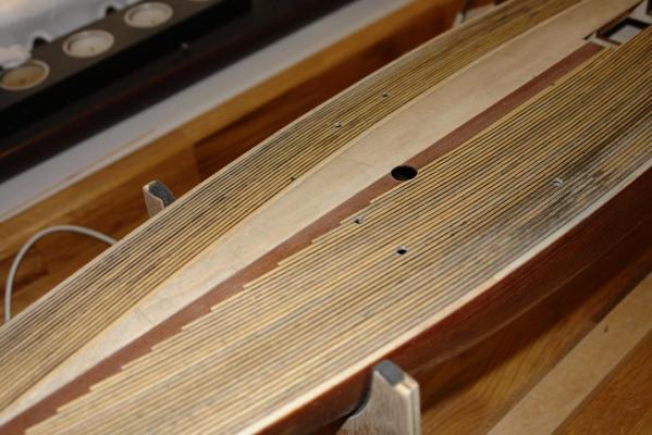
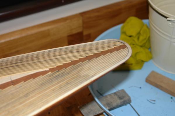
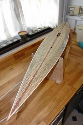
The deck. The Amati version of the model has a number of deck features that do not appear on the 1989 restoration. In particular the 1934 version has washboards at the deck edge and handrails (see photo) a number of planks in from the edge. These features would obviously complicate the laying and sanding of the deck and I was pleased to be able to avoid them. In the Amati kit version the 2.5mm (0.10") by 0.75mm (.030") deck planks are laid commencing at the deck edge, with planks being adjacent to one another without special attention being paid to caulking. I decided to experiment to see if I could achieve a more realistic finish. The following test piece shows the 3 options I considered (all have been sanded). Option 1 - is as Amati envisaged - the effect isn't a distinctive as I wanted. Option 2 - I have used a felt pen to colour the plank edges before assembly - rejected because the bleed of the edge colour is uneven and unsightly. Option 3 - I have laid 1mm (.040") strips of thin black card between the planks - this is the option I chose. The Amati build suggests laying a few planks along the centreline of the deck before proceeding to lay the deck commencing at the deck edge. The edge planks being tapered to conform with the deck centreline planks where they meet. To enhance the deck further I laid a mahogany central deck strip and "notched" the deck edge strips into this to give a more attractive finish. The following photographs illustrate progress. The first photographs show a number of deck planks (and paper caulking strips) in place and notched into the central mahogany strip. The end of one of card caulking strips can be seen in the middle of the deck. The next photograph show the deck at the stern. I have sanded a small area to make sure the effect that I wanted was being achieved. The next few images display progress. This final 2 images show the deck complete with a first coat of varnish. (A few deck features are in place - they were produced as a diversion from the tedium of laying the deck)


-
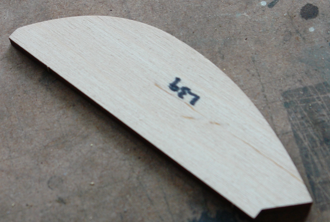
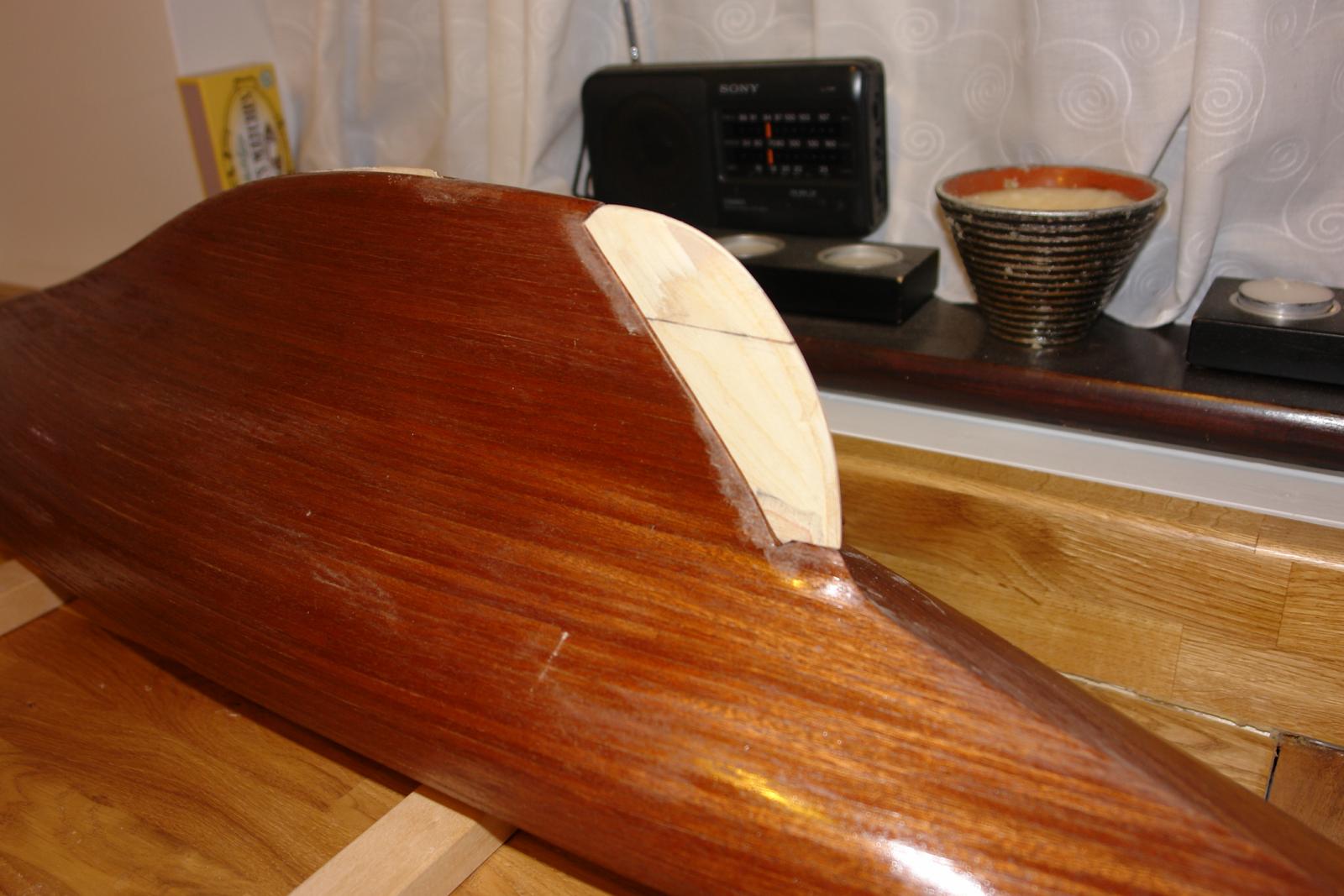
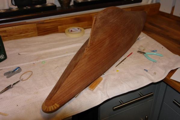
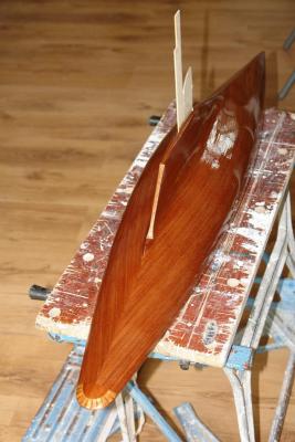
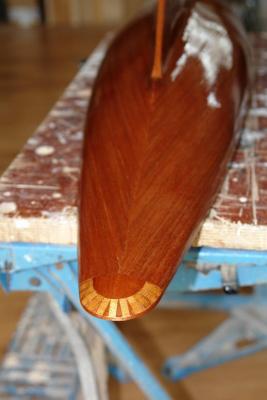
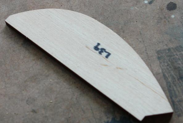
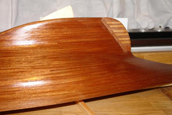
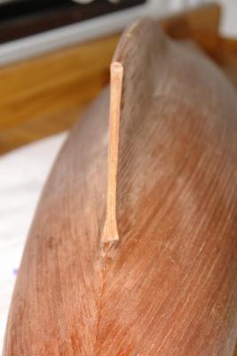
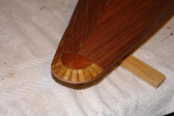
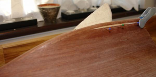
Finishing the hull and rudder. I decided to paint the hull with clear satin finish varnish. I tend to brush paint large hulls even though I do have an air brush. I thin the varnish so that it is quite fluid as as I find this gives a more consistent finish. I apply the varnish quite thinly and take care to check for any runs during the paint application as it much easier to correct at this stage. I always brush along the planks. I expected to have to apply at least 4 coats but in the end applied 5. I allowed 1 day for each coat to dry and sanded between coats with 600 grit wet and dry (used dry). After sanding I wiped down the hull with a wet lint free cloth to remove all dust before the next coat. Photos pre and post first coat - the varnish is still wet. (Note the drop keel still covered in protective masking tape and propped in the open position by a spare piece of balsa). Having completed the first 2 coats I made and attached the rudder. The kit provides 2 rudder plywood cut outs (one shown in photo) each 5mm (0.2") thick and indicates these are to be glued together before shaping. The reason for the double thickness is that the rudder has to be thicker than 5mm at top and bottom to flare smoothly into the hull and the keel. The kit method of forming the rudder to me seemed to involve excessive sanding and I took a single thickness of rudder and applied a few left over hull planks at the top and the button to give me the extra thickness needed for shaping. I then sanded the rudder using the hull as a guide to make sure that the flaring was correct. See photos - The rudder was finished slightly under size as I planned to plank it with to match the hull. I also wanted to give it some highlights. See photos The final photo shows the rudder attached to the hull with all 5 varnish coats applied.

-
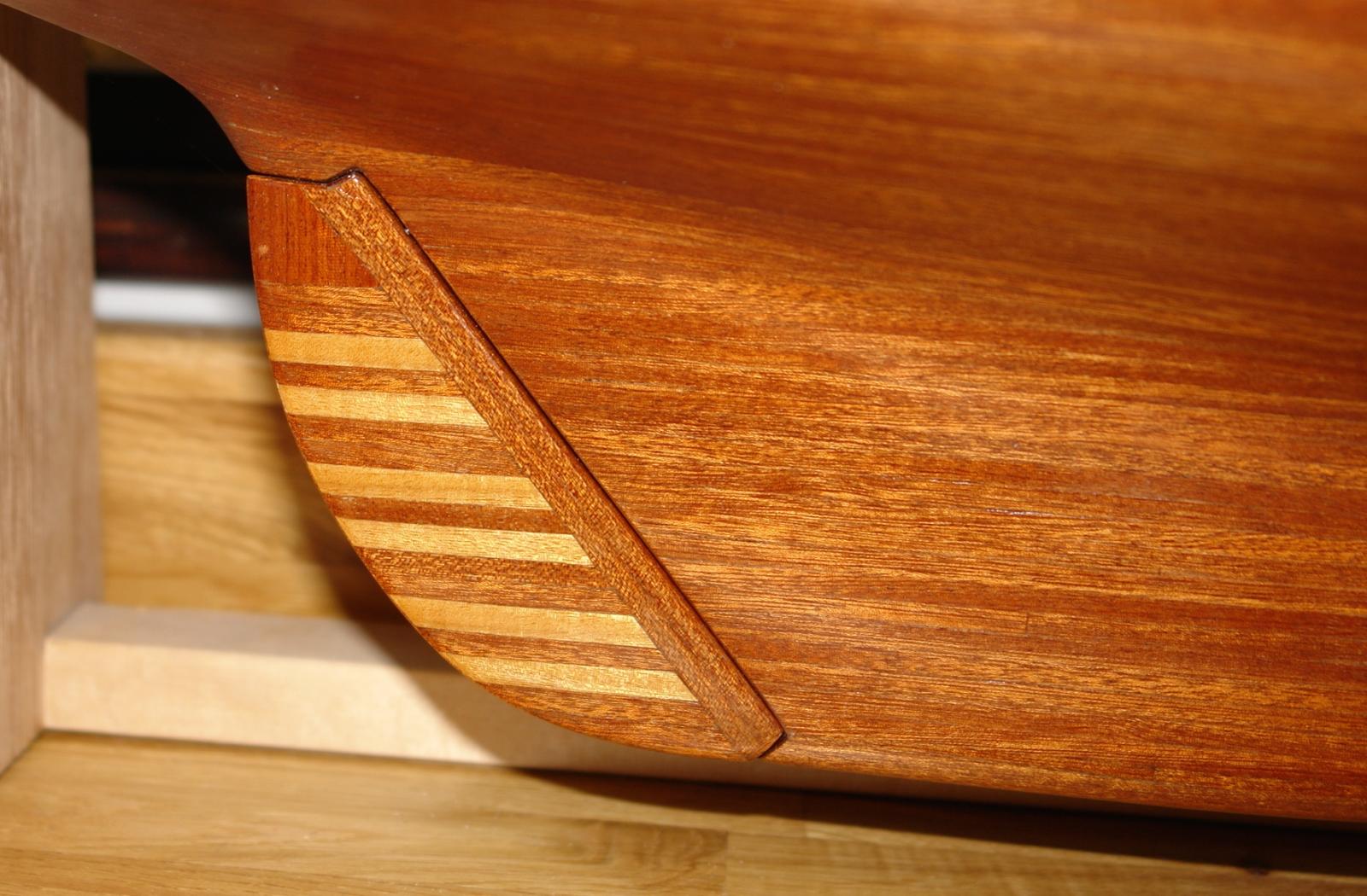
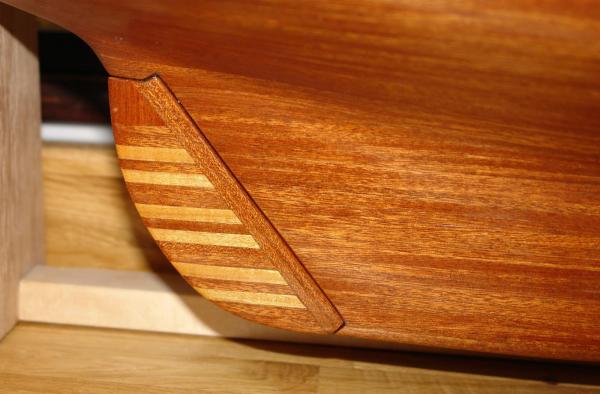
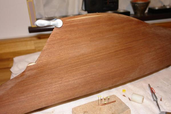
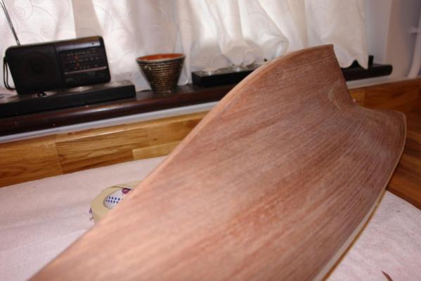
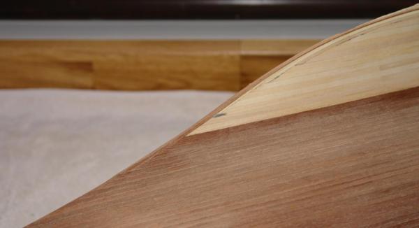
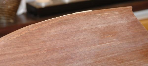
2nd Planking 2nd side. Yves - thank you for the comment. The second side is in the main a repeat of the 1st with a few additions. As before I will cover it mainly by photos. In the 4th photo you can see the nylon (white) roller that I used to press the second planks down during gluing. Also you can see that a small section of 2nd planking is missing from the hull at the upper end of the rudder. This piece has a significant curvature and you can see it pinned on to the cork block. This piece is drying having been soaked in boiling water and bent to the correct shape before being held in shape with pins. I can get a bit obsessive, even planking areas that will not be visible on the final hull. The next photograph sows a case in point. This area was also planked. Having completed the second planking it was time for sanding. You will have seen from earlier posts that I was concerned not to sand through the 2nd planks and I was therefore very careful during the sanding operation. All sanding was done manually using wet and dry paper (used dry), progressively using 120, 240, 400 grit. Pressure was kept light with frequent checks on the surface to ensure that the desired shape was being achieved while minimising surface removal. Finally for this post I needed to finish the stern. I decided to give the hull a few high-lights and this was one of them (the hull has been wiped with a damp cloth to bring out the colour).


- 85 replies
-
- 10
-
-
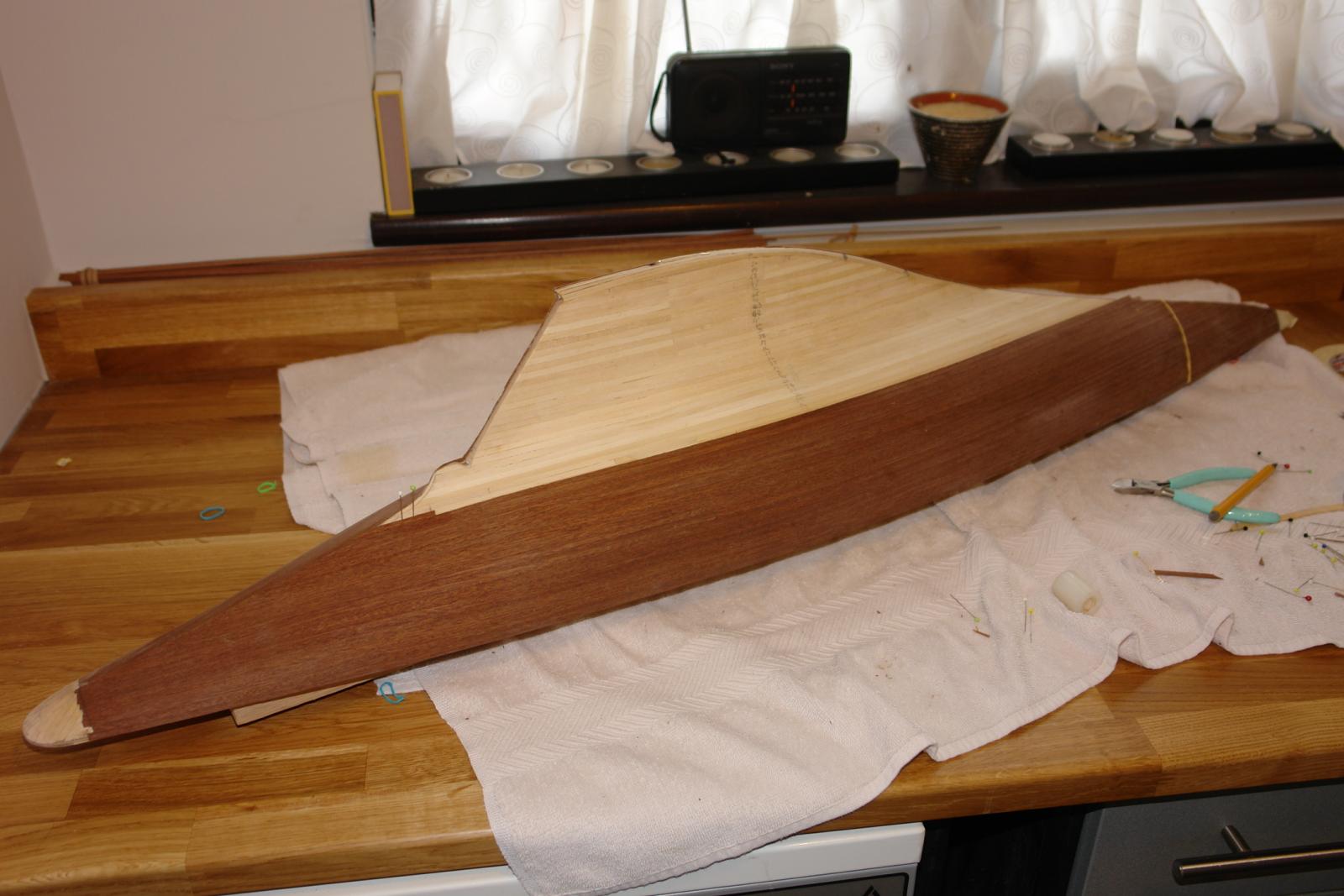
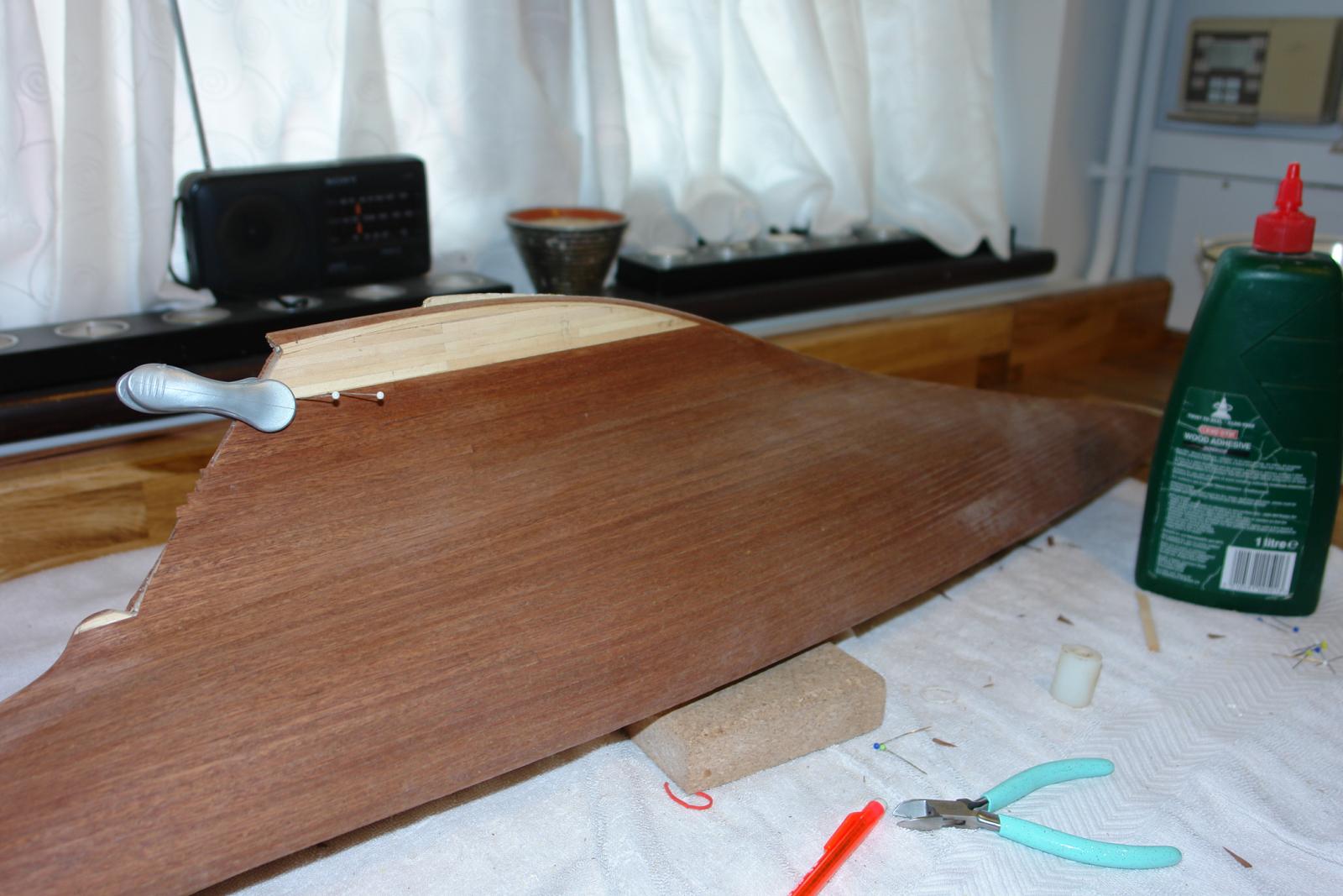
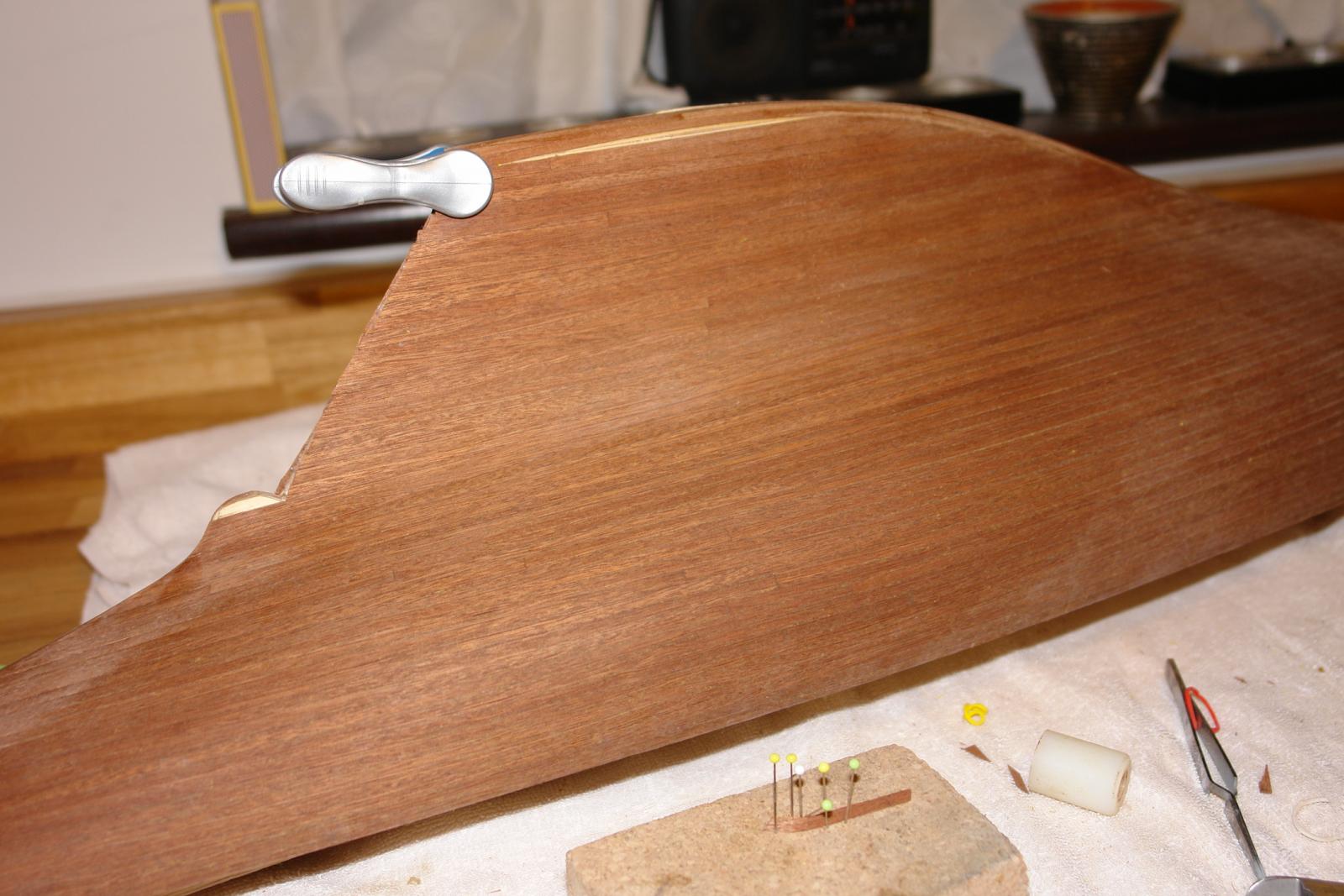
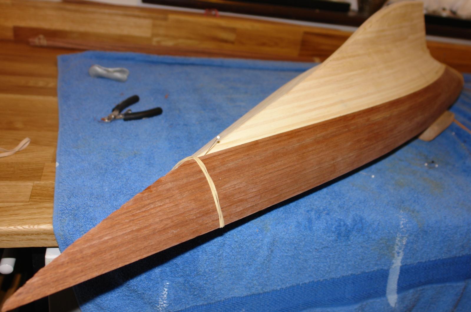
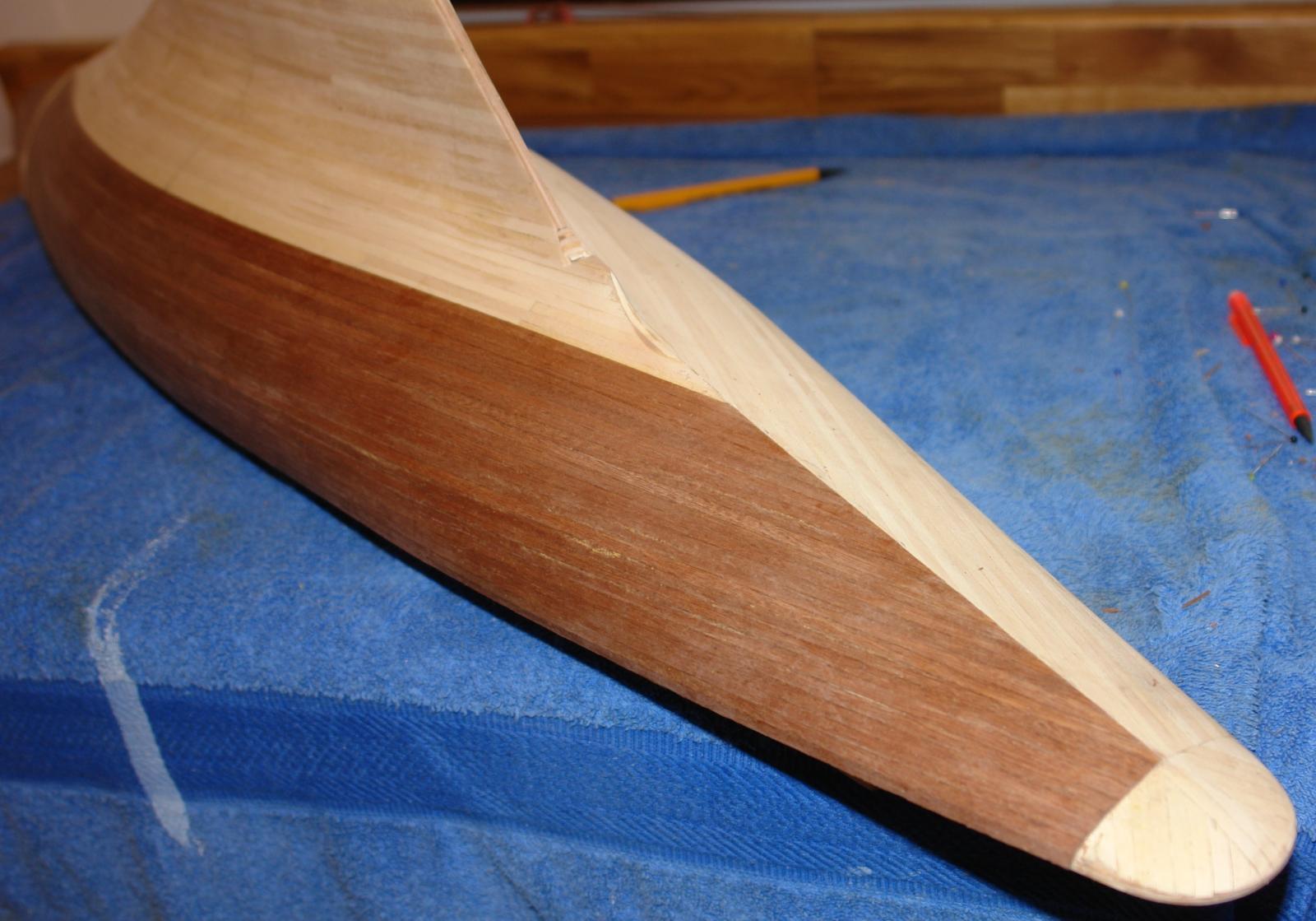
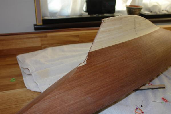
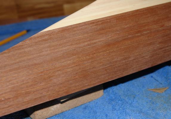
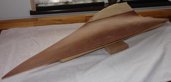
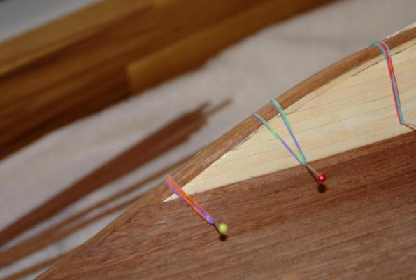
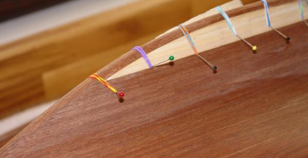
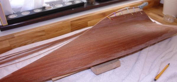
2nd planking - 1st side I am going to cover this mainly in photographs with comments appended. The kit sequence for planking is 1st planking, 2nd mahogany planking, plywood sub deck then deck edge strip. This is ok if the sides of the hull are to be painted as the exposed plywood and deck edge plank will be covered. As i was planning a mahogany finished hull I needed to have the deck edge covered in mahogany hence my sequence of 1st planking, deck, 2nd mahogany planking. One advantage of my sequence is that the 1st and second planks are offset by circa 2mm (.080") - the thickness of the sub deck and deck edge strip. I believe this aids the smoothness of finish. The mahogany planks are 4mm (.160") x 0.5mm (.020"). Because the planks are very thin they need to be applied uniformly and smoothly so that sanding can be minimised. The next 2 images show about 1/3 of the planks applied. The planks are glued with wood glue and pressed in place by a hard nylon roller. In the second photo the 1st planking finish at the stern can be seen. This is as recommended in the kit. More planks. As the stem starts to transition from sharp to rounded, 2.5mm wide strips are laid along the length of the keel. More easily seen in the 2nd image. More strips along the keel and then more hull planks etc. etc. In the 2nd to last photo the drop keel can be seen - at this stage covered in masking tape to protect the polished bass surface. None of the planking has been sanded at this stage. Next time I will cover finishing the hull planking.


- 85 replies
-
- 10
-
-
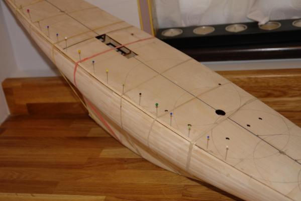
The sub deck. Thank you for the comments on 1st planking - I should probably have said that the sanding was manual - using a cork sanding block. I lightly sanded with 80 grit oxide paper and completed with 120 grit. The next step was to fit the plywood sub deck (2 pieces) and the strips around the deck edge. This wasn't a difficult operation and requires little description here. I aligned and held the deck in place with elastic bands before drilling 0.75mm (.030") holes at strategic points to take alignment pins (e.g. white headed pin in photo). I then removed the sub deck glued and re-fixed it with the alignment pins in place. The alignment pins prevented any movement while gluing. The deck was held in place by elastic bands while the glue dried. Elastic bands can tend to exert most pressure at the deck edge and an off cut of wood was placed along the length of the deck to ensure pressure was also applied to centre of the sub deck. See Photo I sanded the edge of plywood sub deck to mach the hull profile before proceeding to the next stage. Because I was building the 1989 version of Endeavour the deck planking was going to be different to that described in the kit instructions. I will cover deck planking in more detail in a later post. The relevance to this post is that I could use spare 1mm X 4mm hull planking to edge the deck. The deck edge plank needed to bend to follow the edge of the deck quite precisely and I used pins to make sure that it was glued in the correct position (again using elastic bands to hold the edge planking while the glue dried. See photo. The final step was to sand the deck edge planking to match the hull profile. The next post will cover 2nd planking with the 0.5mm (0.020") x 4mm (0.160") mahogany 2nd hull planks. Hopefully the next post will be of more interest than this one.

-
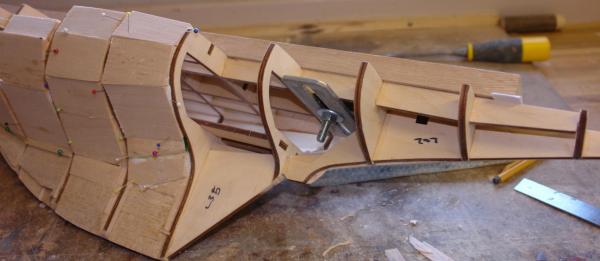
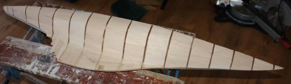
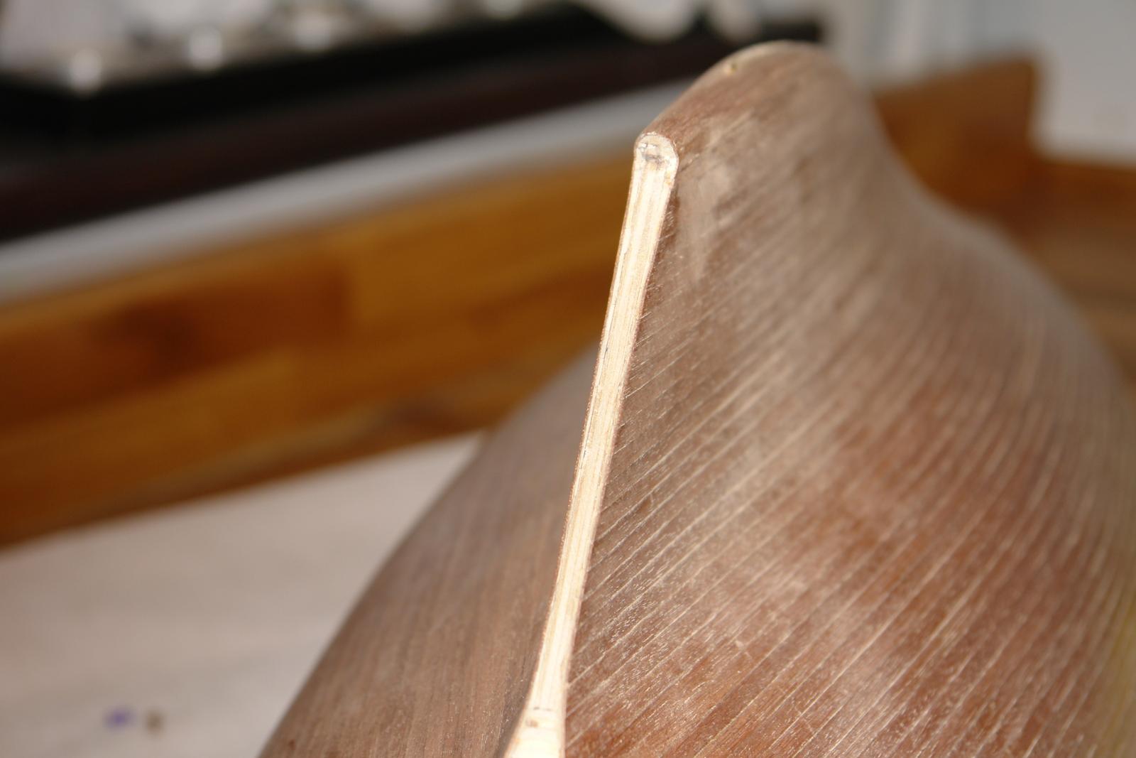
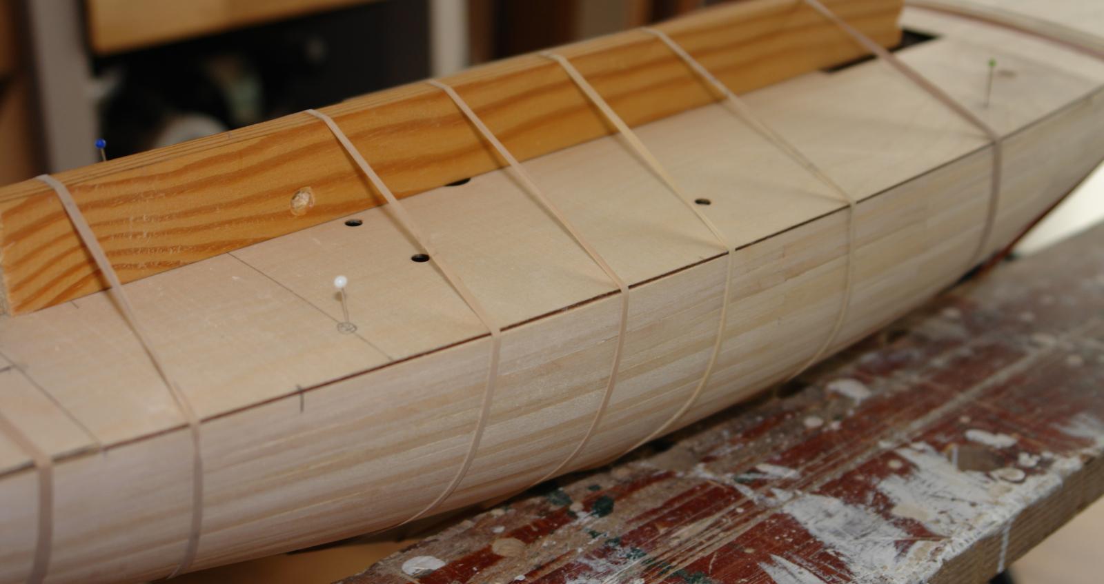
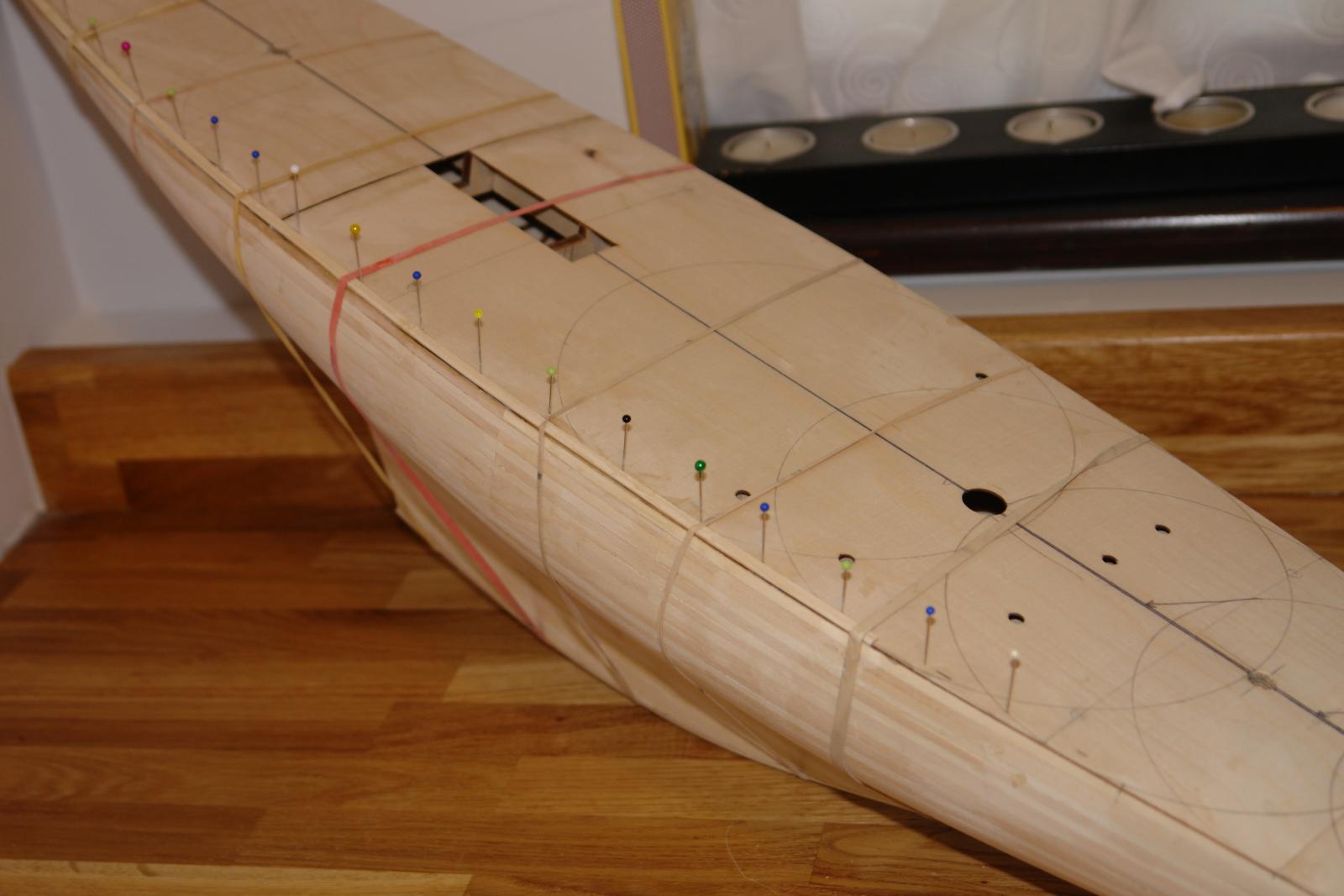
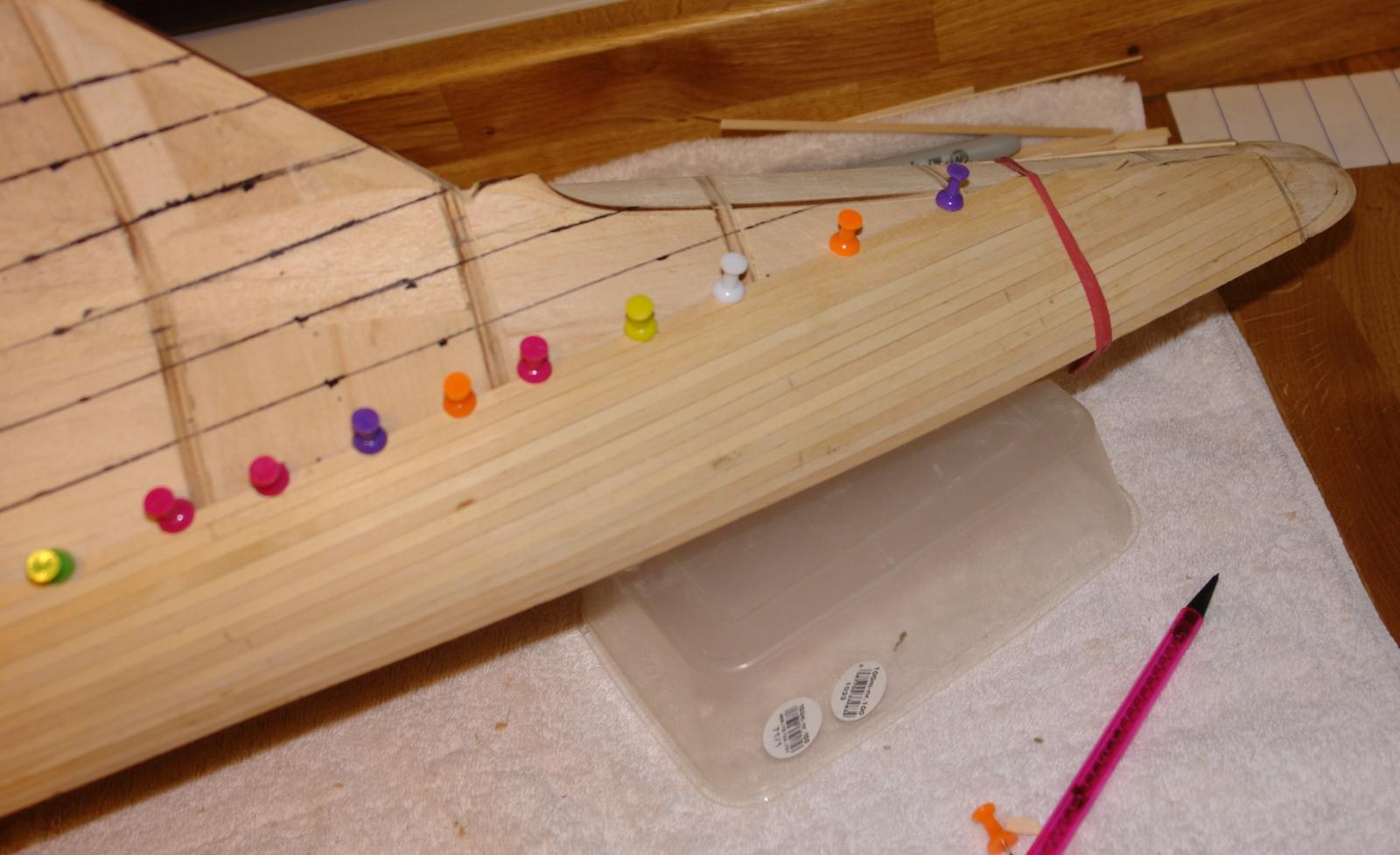
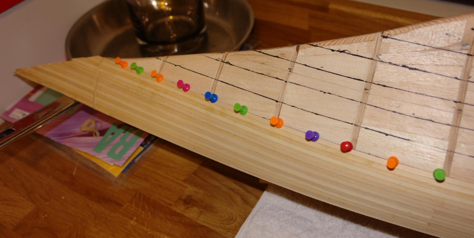
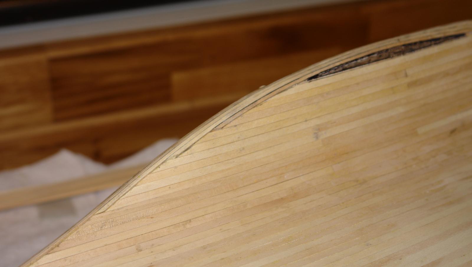
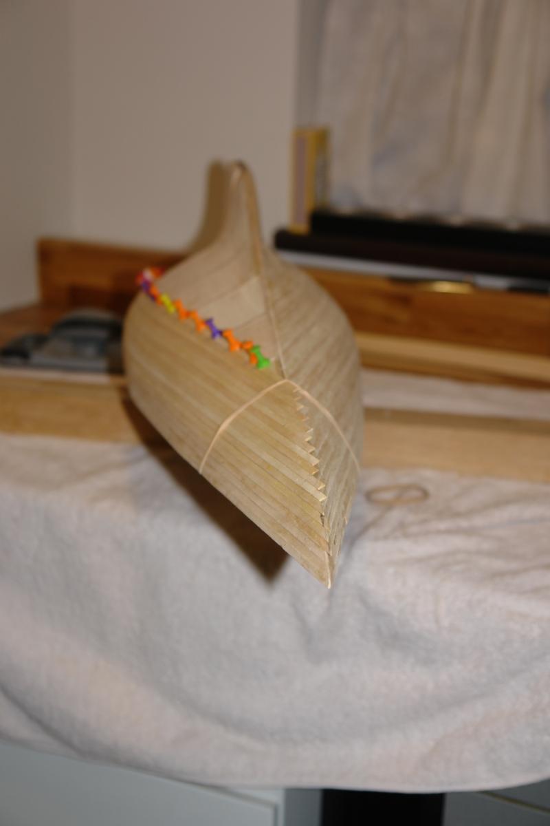
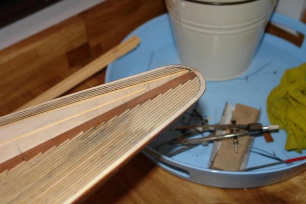
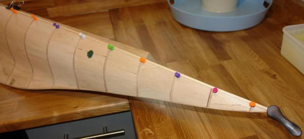
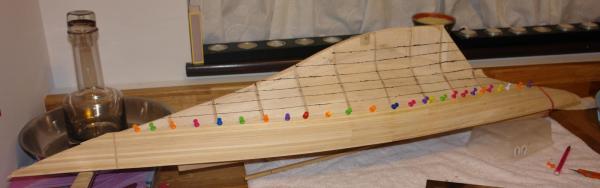
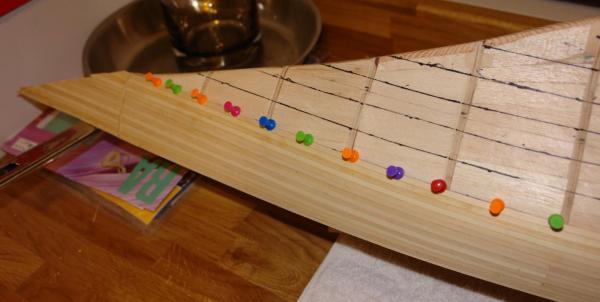
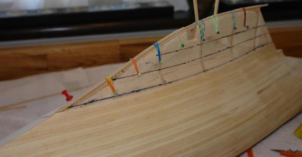
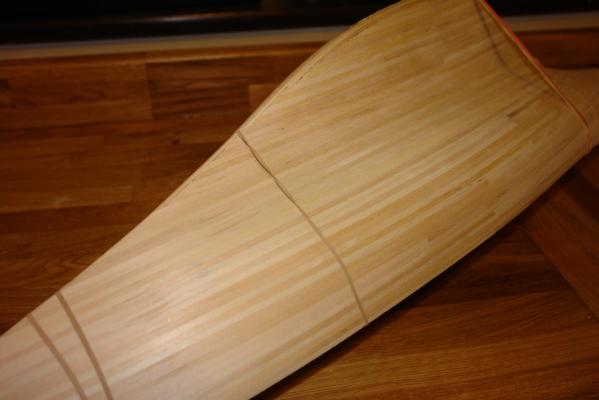
First Planking. The Amati instructions suggest planking the keel bulb first using the 2mm x 2mm strips - these being double the thickness of the standard planks. The instructions suggest that the bulb planking does not exceed a height of 3cm. The instructions then suggest starting the hull planking at deck level and tapering the ends of the planks towards stem and stern. Towards the middle of the hull the kit provides a double width frame on which to start the planks running fore and aft. I wondered if I could make the first planking simpler and decided to try a different approach. I started at deck level. The balsa backing has a number of advantages when planking - the first being that planks can be held in place by notice board pins while the glue dries. See photo. I proceeded adding planks until I had about 10 rows of planks in place. Because of the balsa backing the hull was already rigid and this allowed me to plank one side, rather that doing both sides simultaneously. Also I didn't need to worry about always starting the planks at the double width frame (I didn't actually fit it) and could stagger alternating layers of planks. This gave a smoother hull shape. Having completed the the first 10 rows I used a piece of card to draw lines on the hull where subsequent rows would fall. This convinced me that I could proceed with further layers without the need to taper the planks to stem and stern. See photo. The next series of photos show progress. As the planking progressed the planks followed closely the lines drawn on the hull. As the planks reached the start of the keel the sharp angle of the bow started to become rounded as it blended into the bulb of the keel. This became the obvious point at which to run 2 of the 2mm x 2mm "bulb planks" along the length of the keel, before proceeding with more of the hull planks. See photo. I found elastic bands very useful for holding the keel strips in place. Also because of the sharp curvature of the keel I did sand off the sides to make them trapezoidal rather than square. Having completed several more hull planks the keel bulb curvature once again indicated that a further 2mm x 2mm strips need to be laid along the keel length. This process continued until the hull planking was almost complete. See photo. The black marking on the previous photograph shows the shape of the final closing plank. This was the only hull plank that I real had to shape. Having completed one side the 2nd side was a repeat of the first. I wanted the final hull to be predominantly varnished mahogany and I knew that the quality of first planking had to be very good. I set myself the challenge of completing the first planking without using any filler. The next photo show the shaded hull (the elastic bands are temporally holding the deck in place). No filler was used and no breakthrough into the balsa backing occurred during sanding. See photo. In the next post I will cover attaching the deck.


-
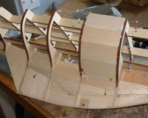
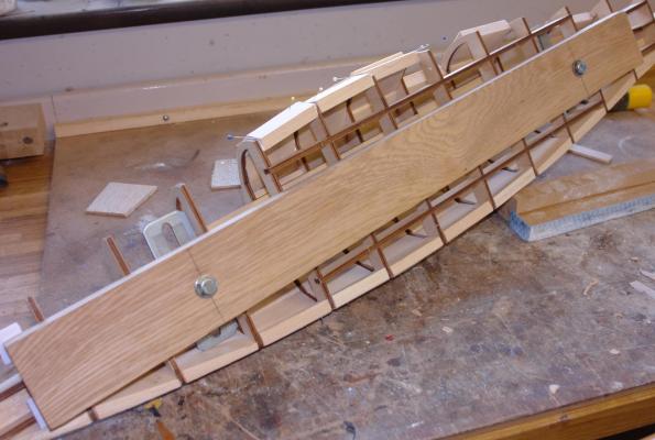
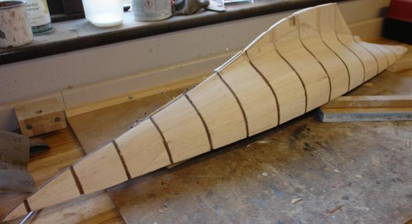
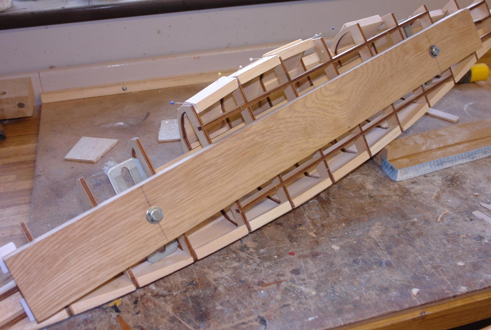
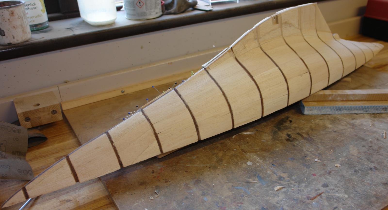
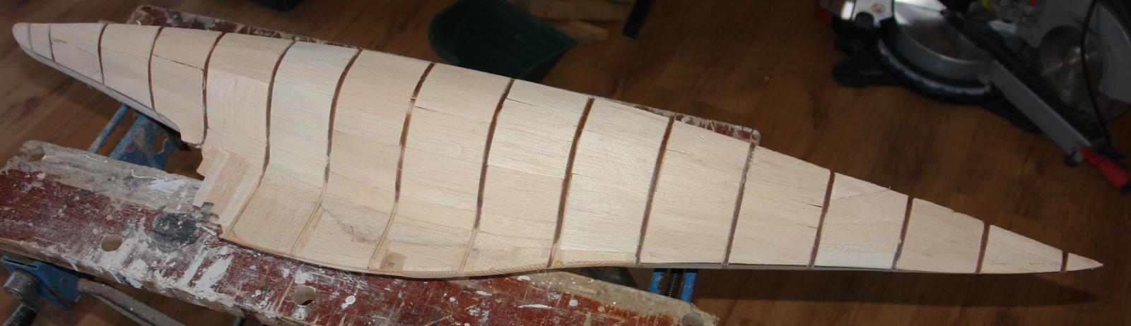
Pondering Planking At 1mm x 4mm (.040" x .160") the 1st planking strips are much thinner than those I have used for planking on previous models. I tend to use 1.5mm (.060") planks on large scratch built hulls. Also the spacing of the frames at circa 75mm (3") is greater than I would have desired. Reading previous posts and based on my own experience I was concerned that the planks would tend not to hold a smooth curve between frames and that sanding to achieve a smooth curve would lead to unacceptable thinning and lack of robustness in the finished hull. I didn't want to discard the kit planks so I decided to back the planks with balsa. A pack of 10 sheets of 12mm x 74mm x 450mm cost me £10 and this was sufficient for the whole hull. The next image shows the start of the process. I mentioned in an earlier post that didn't follow the build instructions and that this gave me a problem. The Amati instructions suggest tacking the the thin plywood deck in place to hold the frames in shape while gluing. I didn't do this and ended up with the assembled frames having a lateral bow of 2mm. I think that following the instructions would have prevented this. Additionally the frames had about a 2 degree twist bow to stern. The deck offers little resistance to twisting and I don't think that tacking the deck in place would have helped prevent this. Using a solid building frame would have been the best option. However both problems were easily resolved by solidly bolting the assembled and glued frame on to a 25mm (1") thick piece of square and flat oak plank. Forcing the frame into the correct shape before completing the balsa backing layer. Once the backing layer was complete it formed a very rigid shell which held the frames in the correct alignment. The next 2 images show the oak "strong back" in place. In retrospect I was very please that I had remembered to check the frame alignment while I still had time to do something about it!!!!!! Having completed the backing layer, sanding was a relatively straight forward. I always try to use a sanding block and sand along the lines of the hull as I find this allows me to form a smooth transition of curvature. Feel is important when shaping the hull and I don't recommend the use of power tools for this operation. I try to get the shape generally correct without sanding down as far as the frames in the first instance. See photo. As can be seen in the previous photograph the edges of the frames have been discoloured brown by the laser cutting operation. This forms a useful guide when finish sanding the backing layer, as once the discolouration is removed the hull has achieved its desired shape and its time for sanding to stop. See Images. With the backing complete it was time to start the base planking. I found the oak strong back useful for holding the hull while working on it and I decided to retain it for the planking operation. I'll cover base planking in my next post.