KeithAug
-
Posts
3,986 -
Joined
-
Last visited
Content Type
Profiles
Forums
Gallery
Events
Everything posted by KeithAug
-
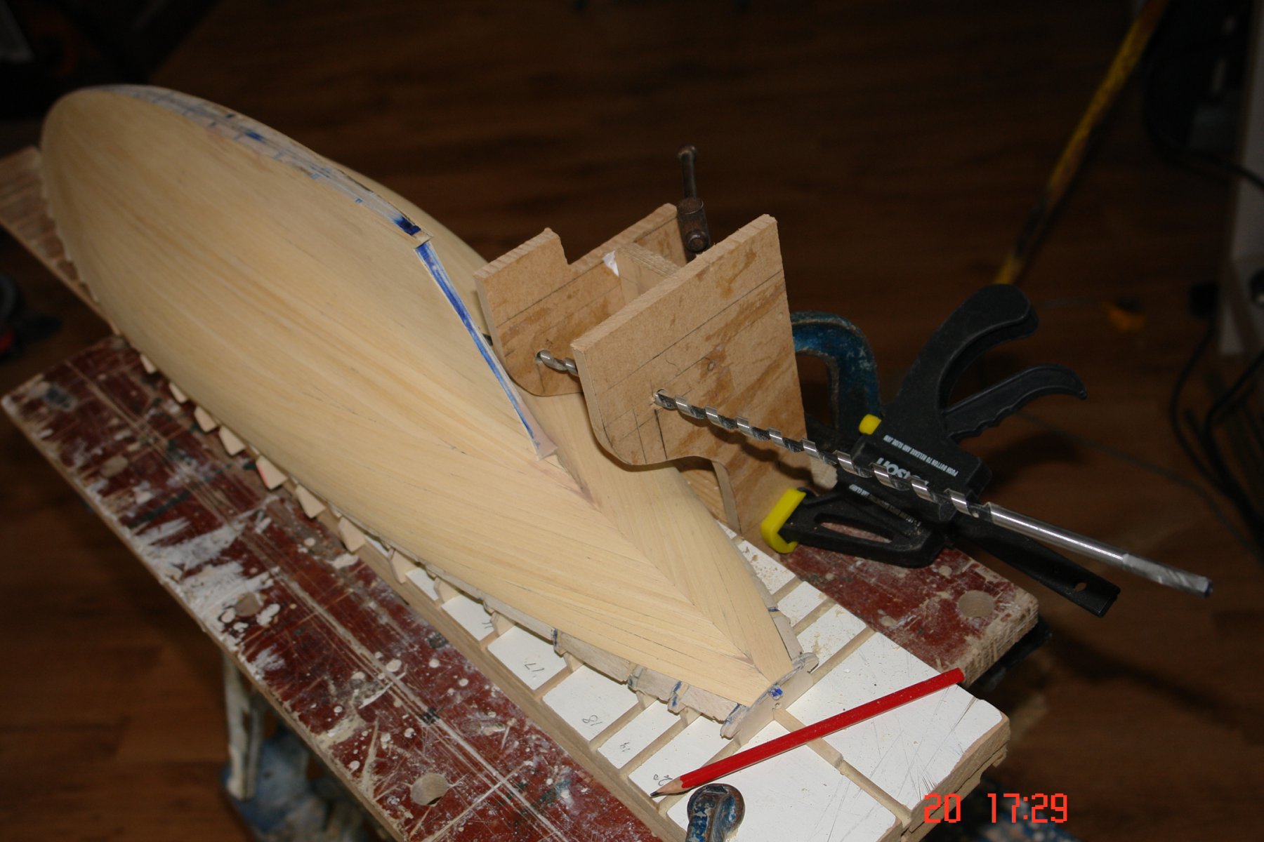
 A jig for drilling the prop shaft hole is a good idea. The attached is a more complex jig than you need but gives an idea of what to do. Basically it is 2 pieces of MDF drilled with holes to align the drill for the prop shaft tube. Nice little model by the way.
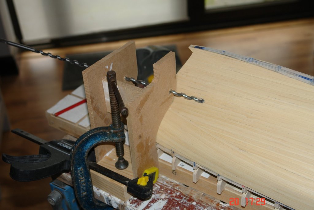

-
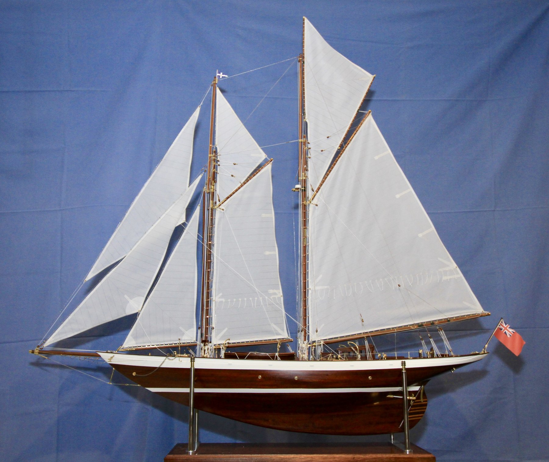
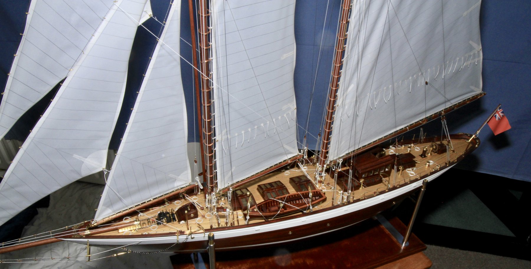
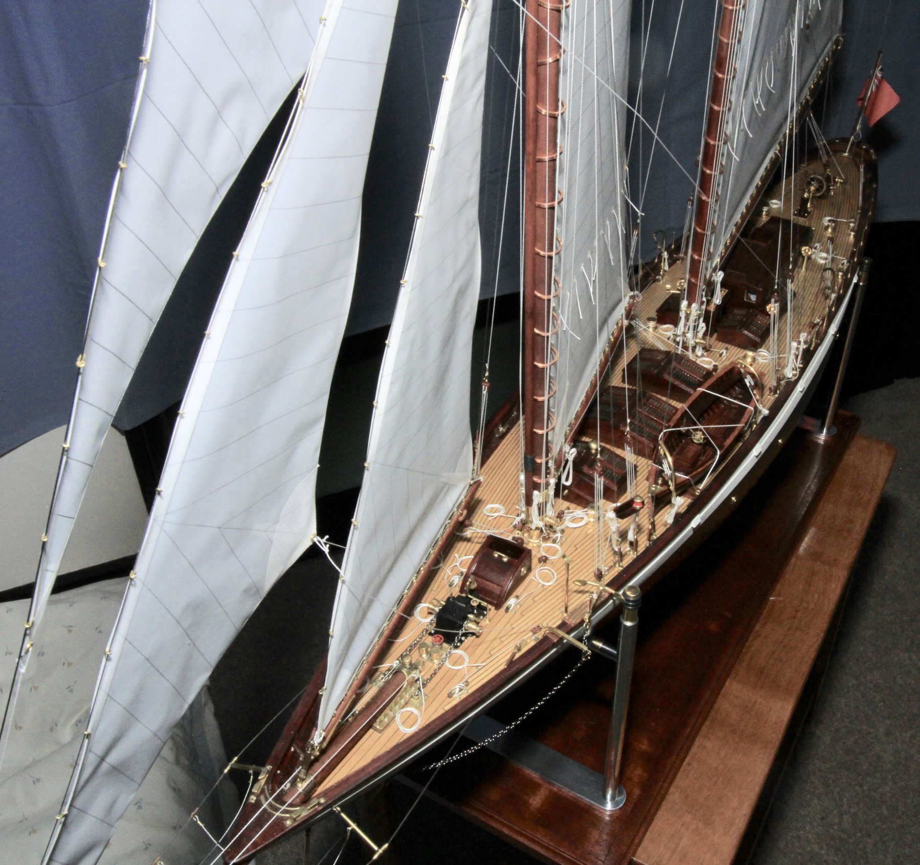
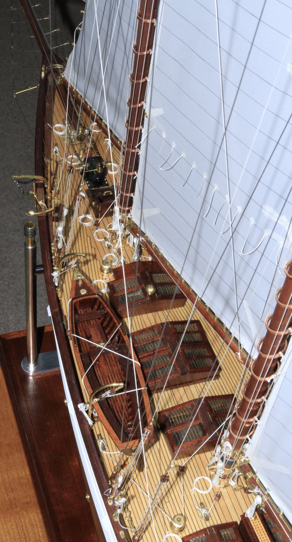
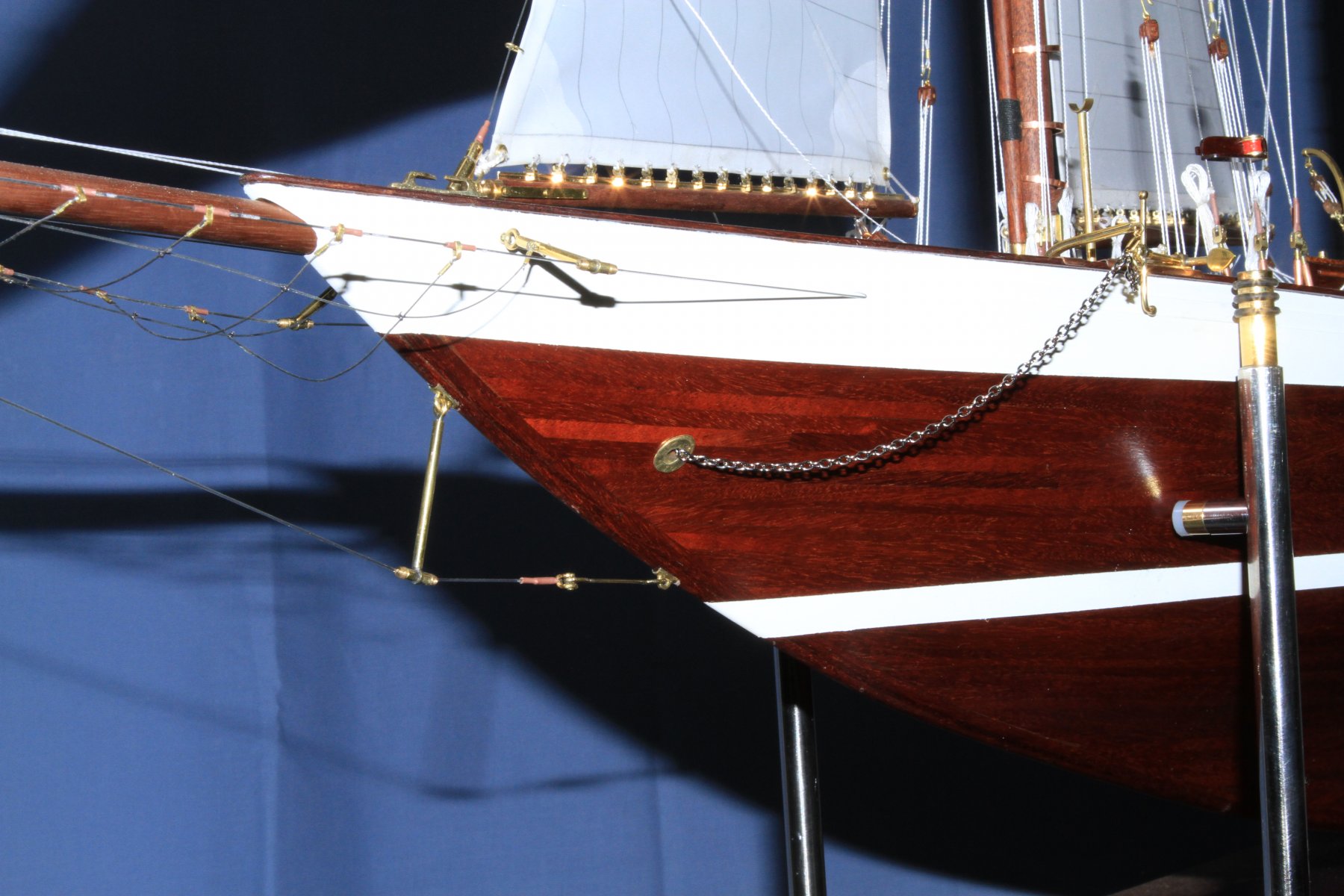
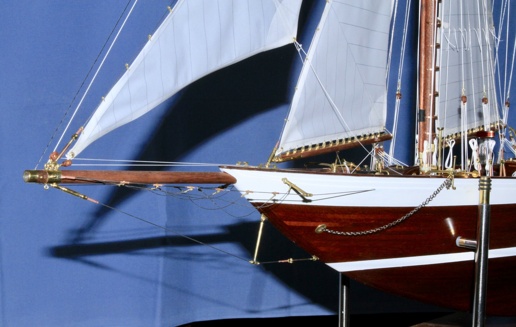
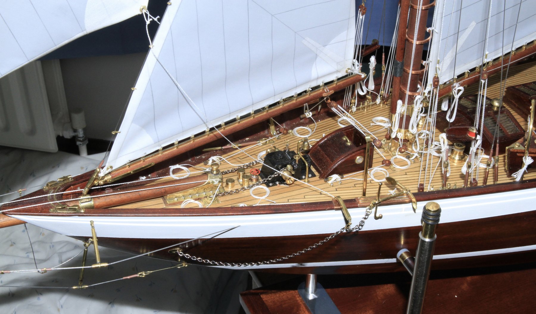
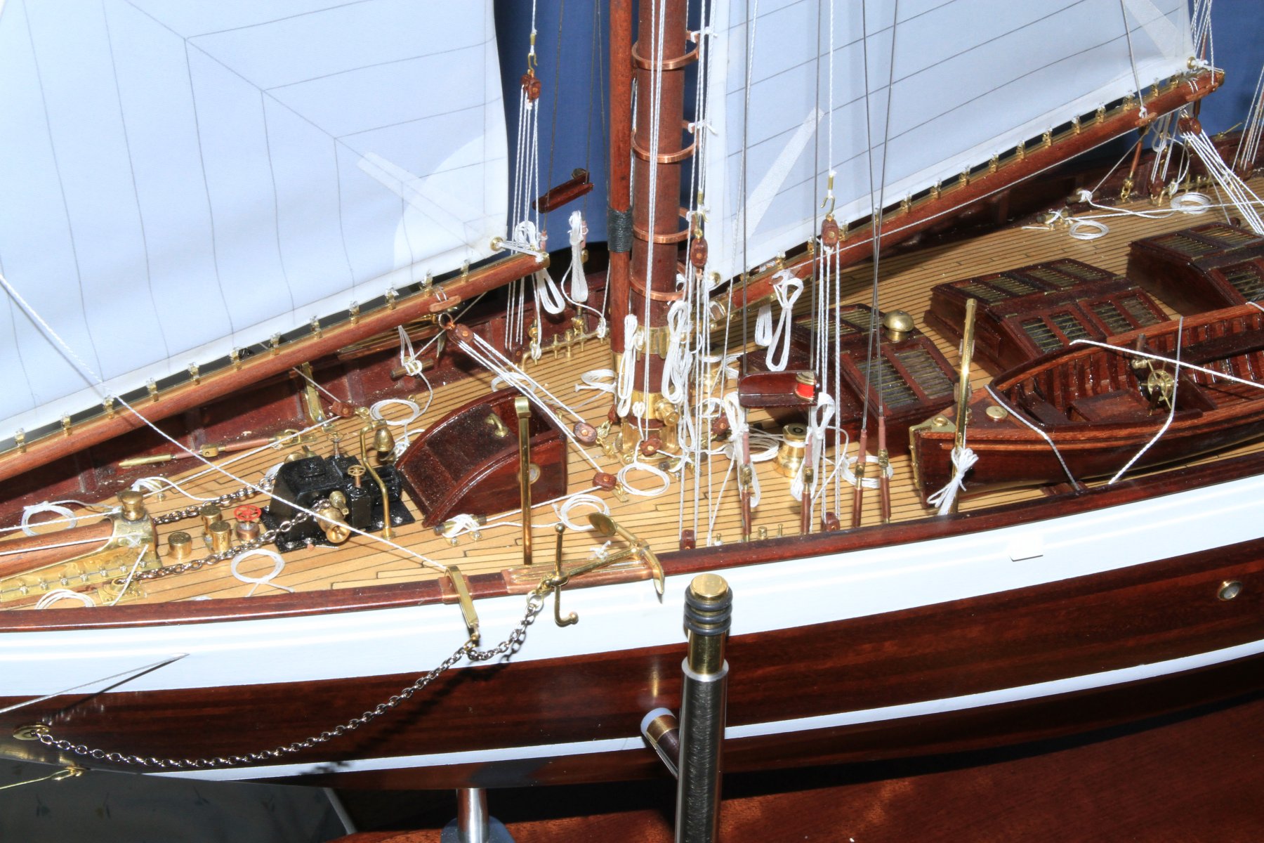
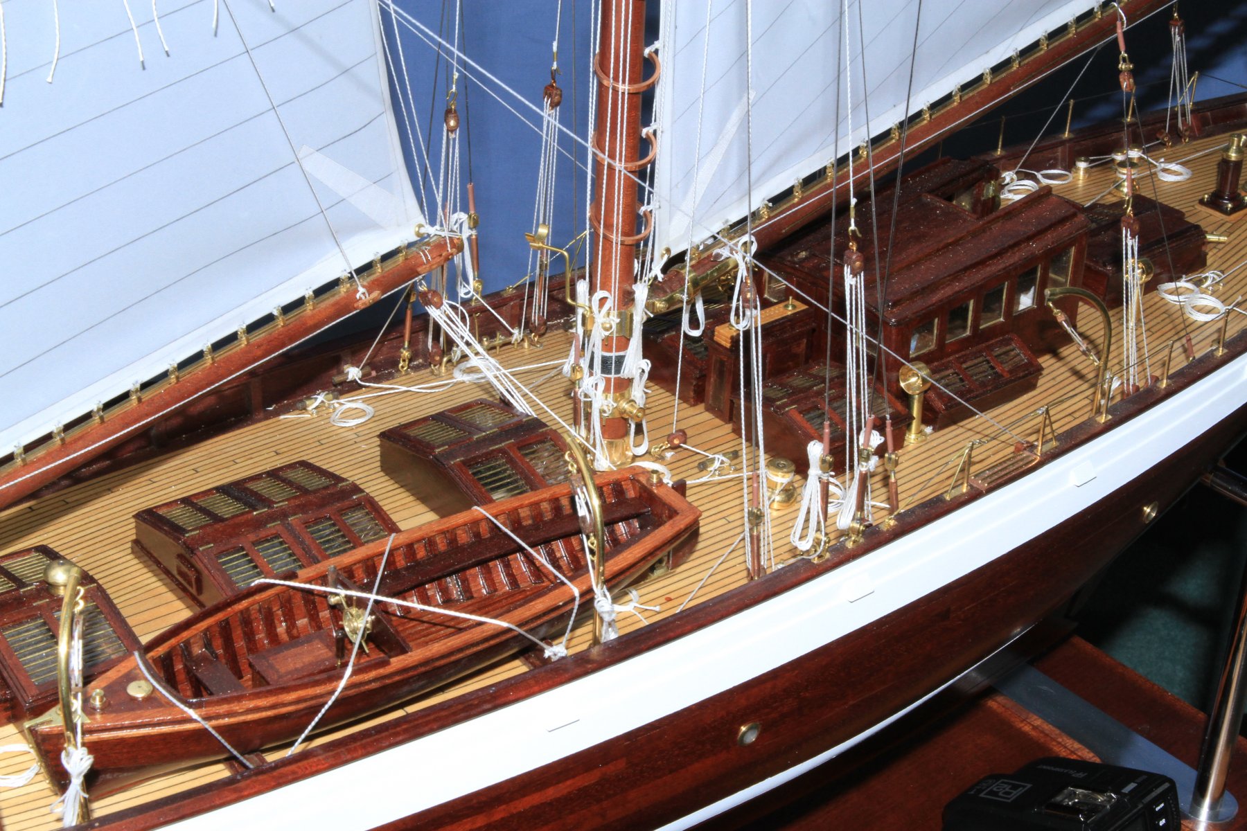
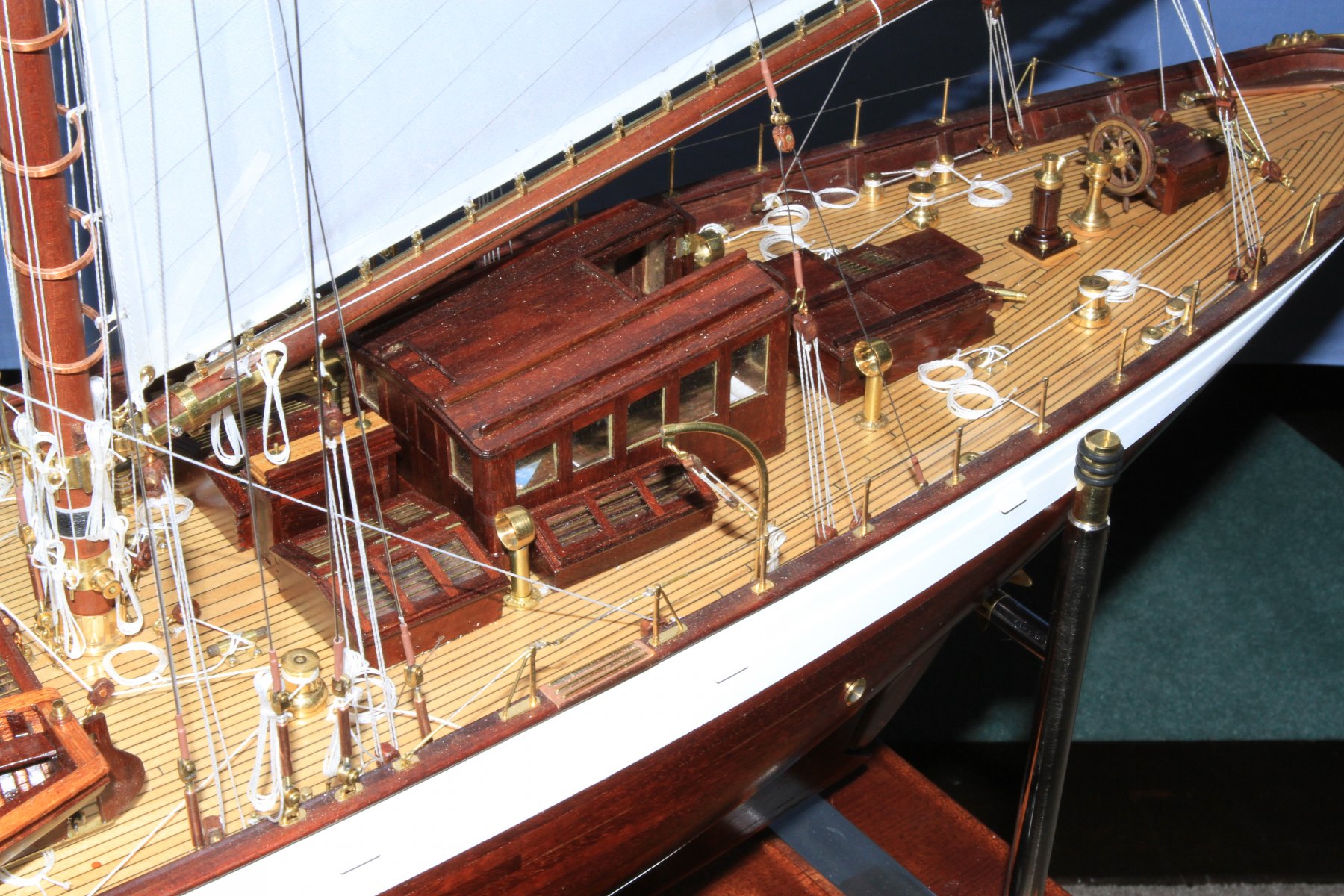
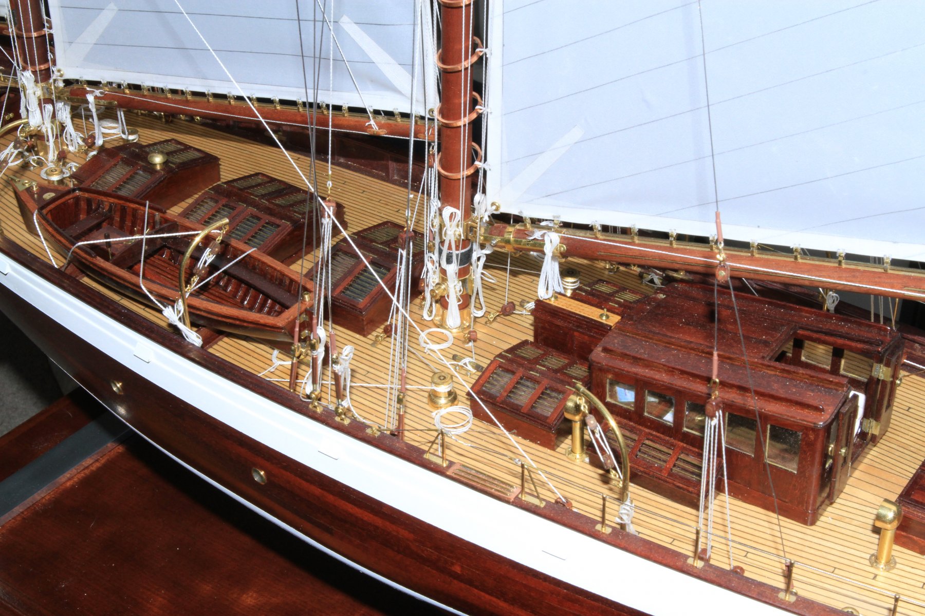
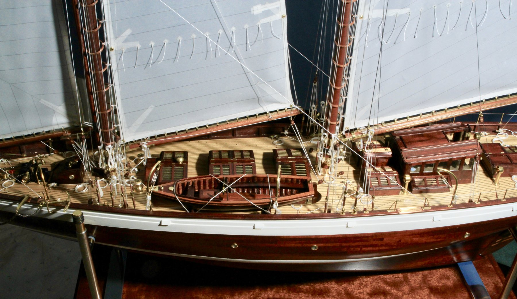
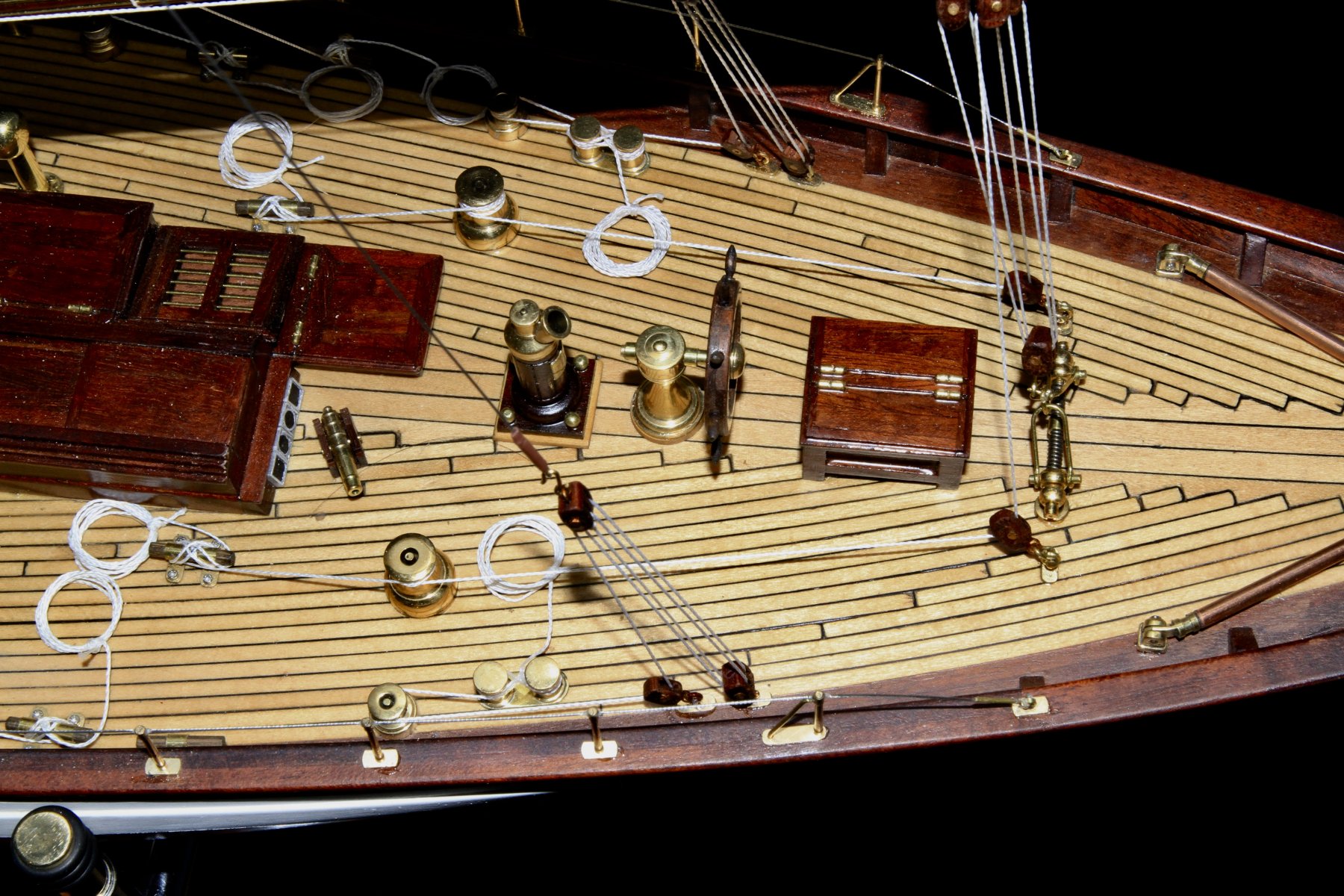
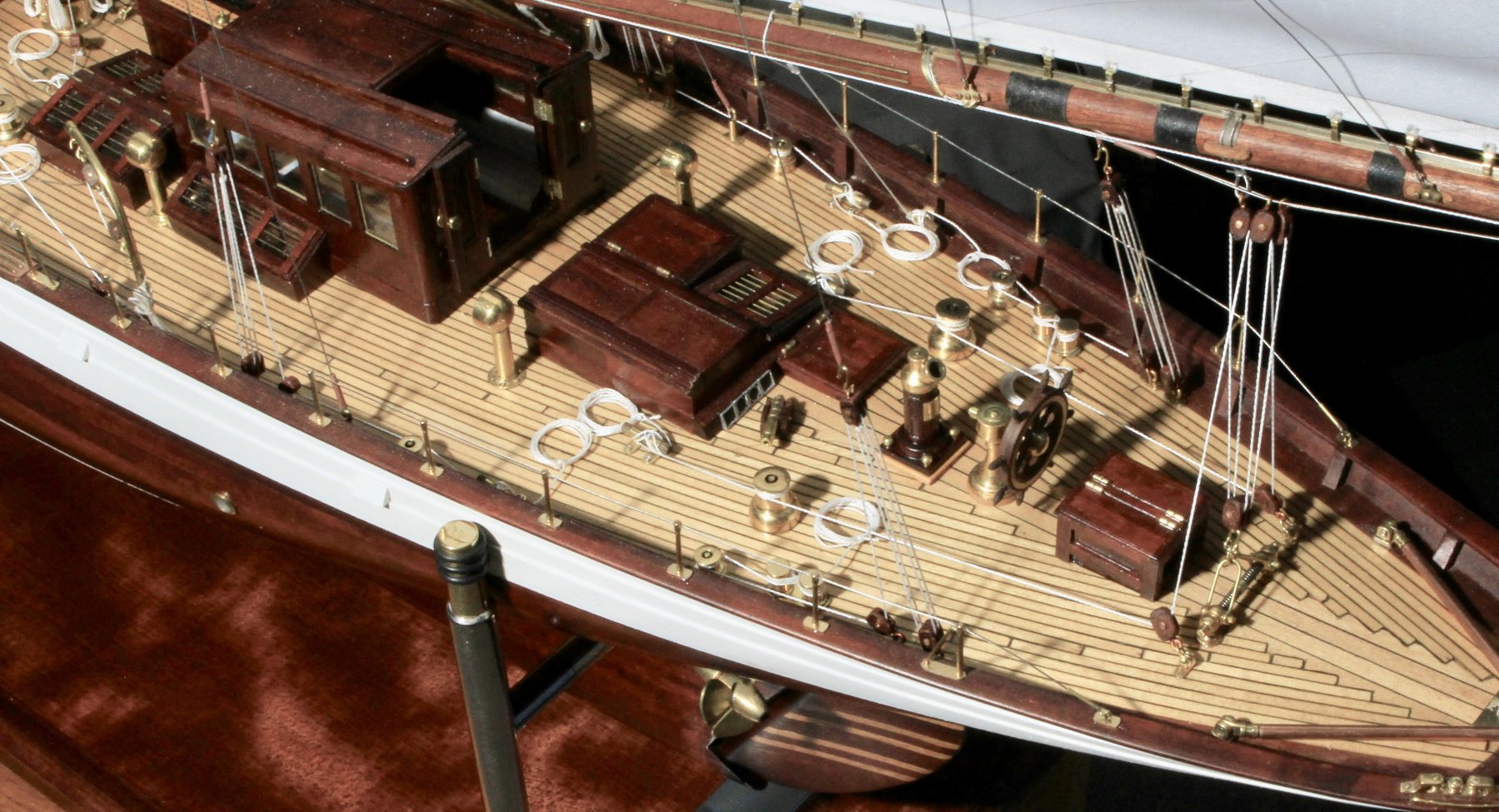
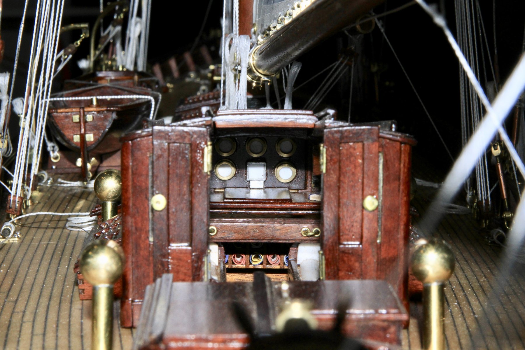
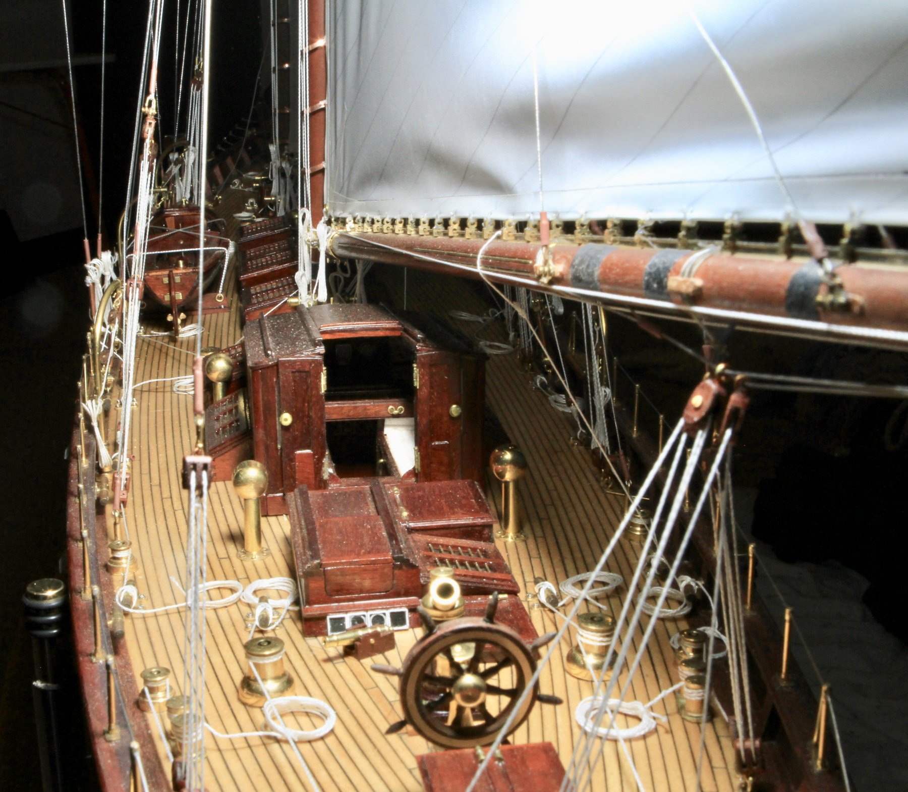
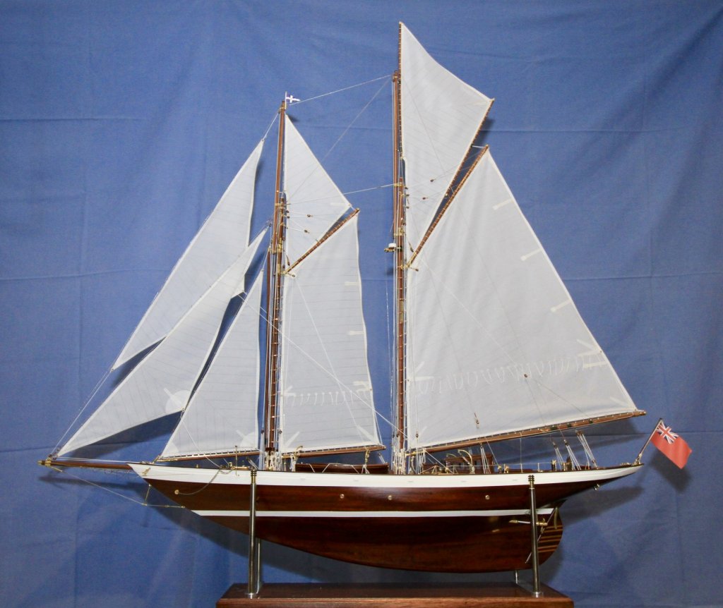
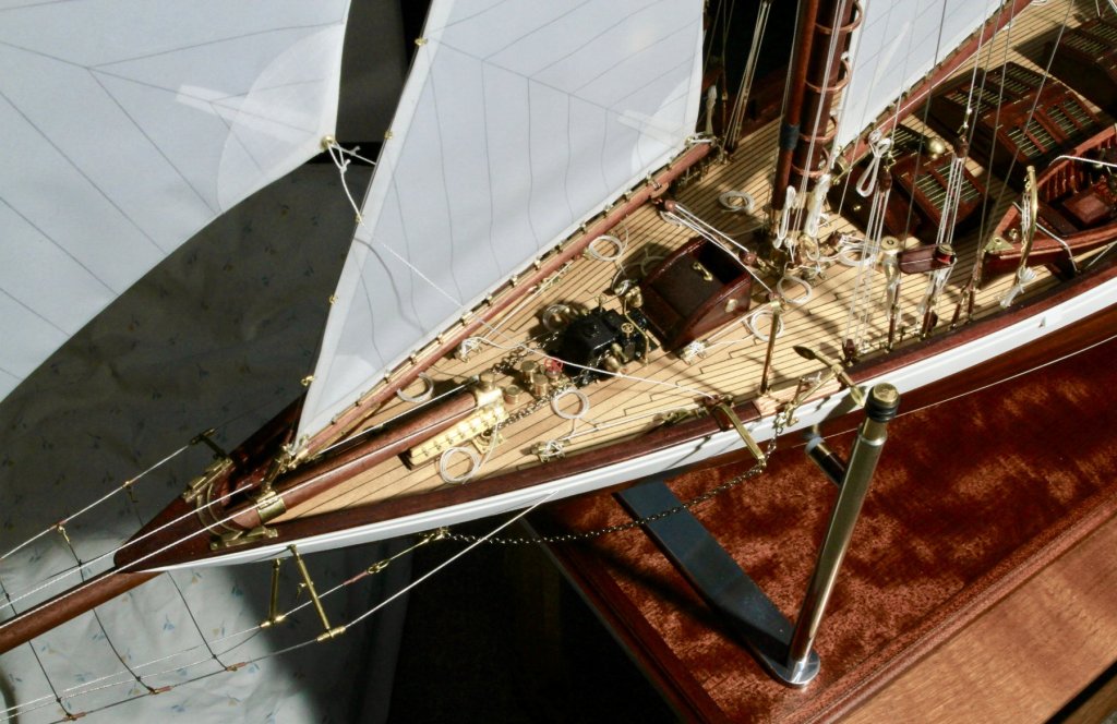
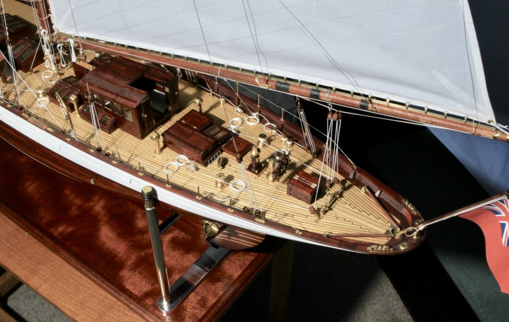
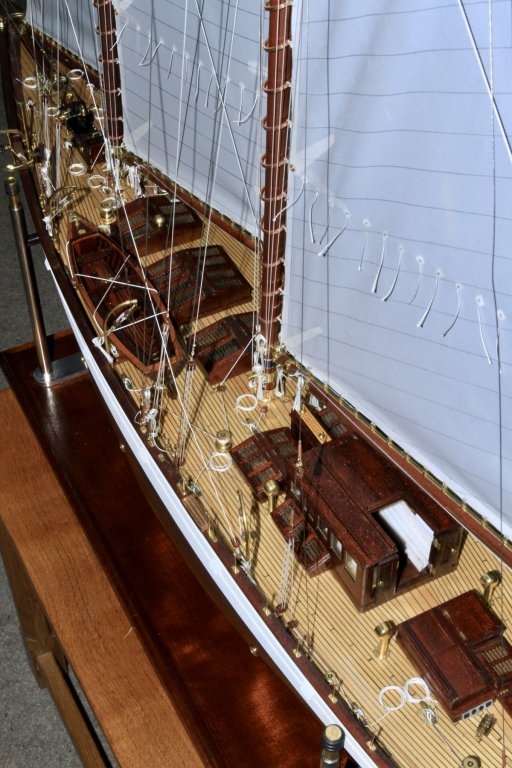
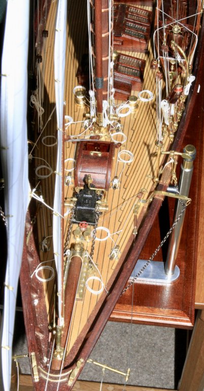
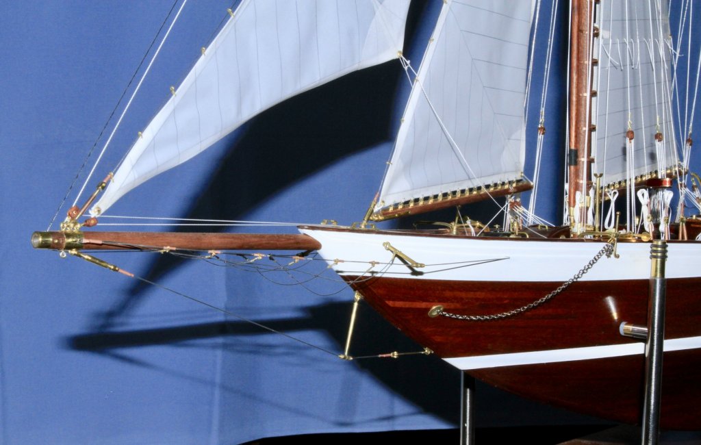
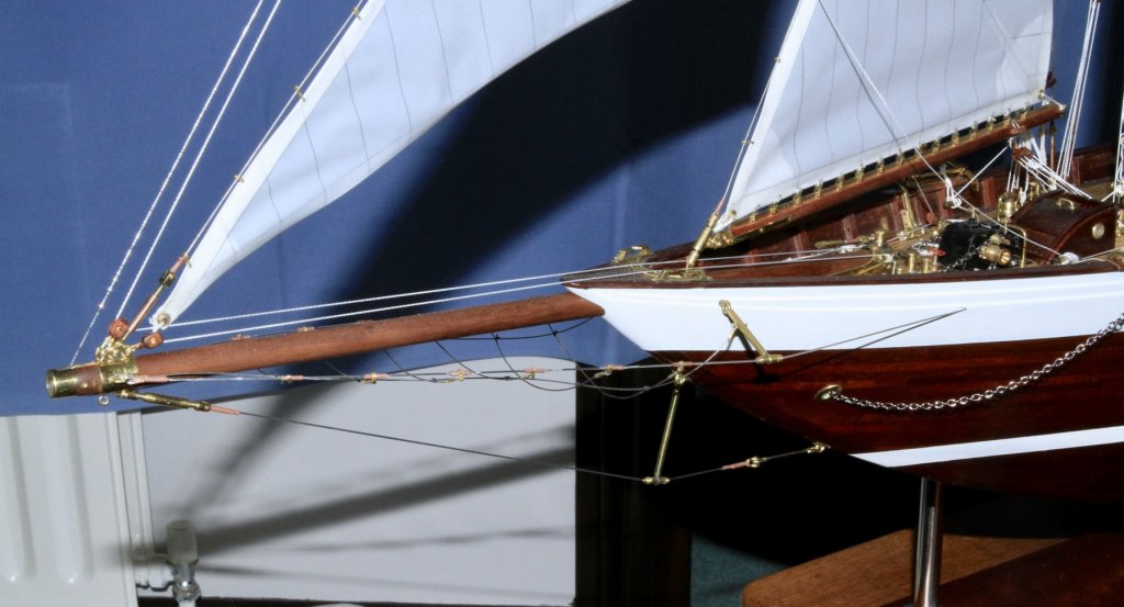
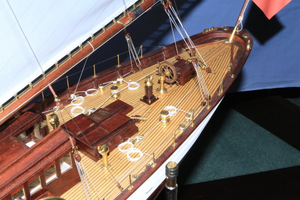
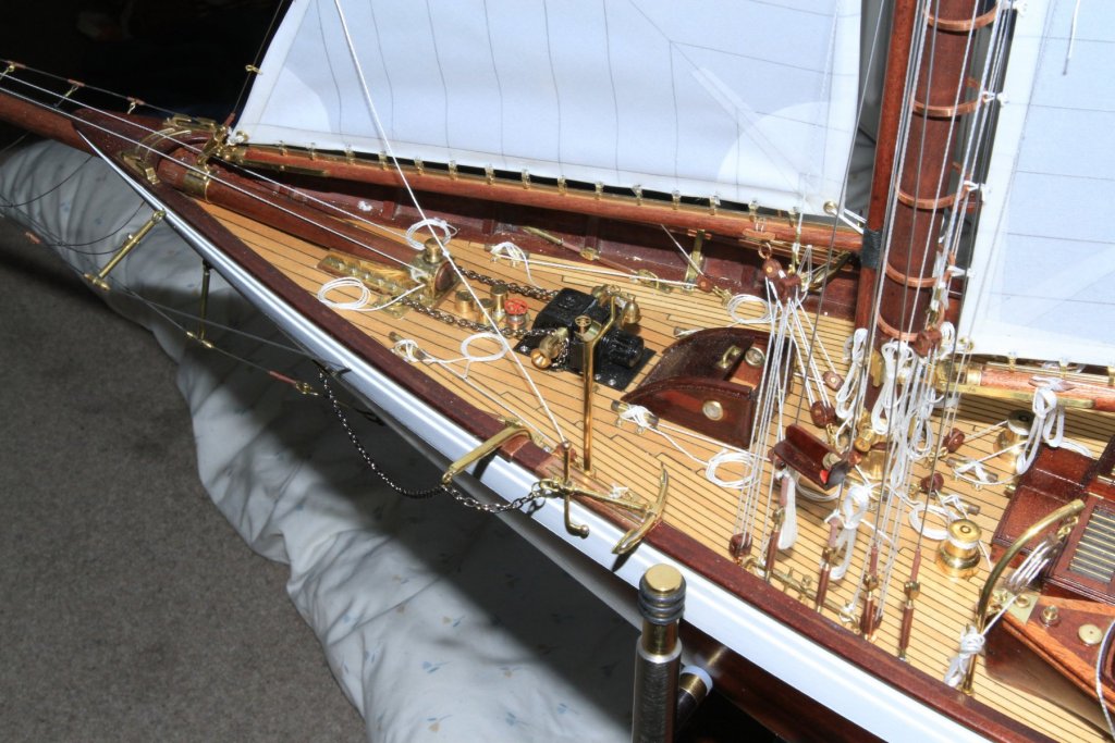
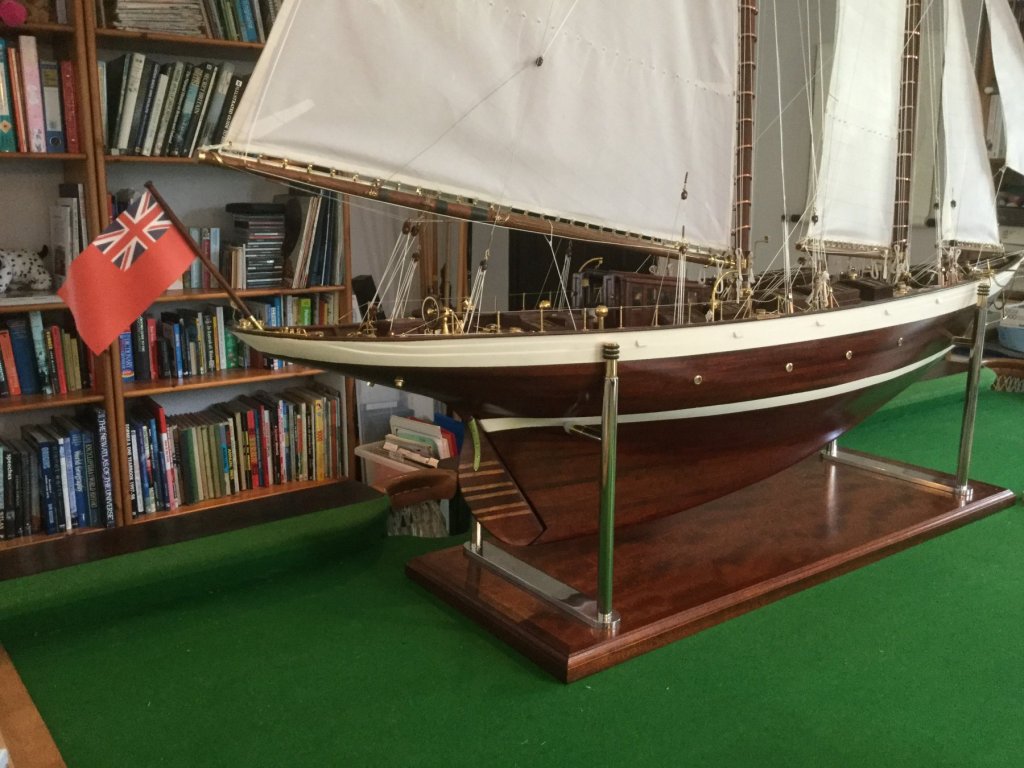
My brother n law came to stay with his superior camera equipment - so lots of photos which blow up quite well for anyone looking for imperfections. I need sort out a finished model post so I may use some of these. Meanwhile my better half seems to have perked up a little and I may bet back to the workshop soon.


- 882 replies
-
- 25
-

-

-
Lovely looking model. Well done.
-
Rok Have you tried this email address? Jim Byrnes <jdm@cfl.rr.com> Keith
-
Nice work Nils. The crewman on the left seems to be a little confused. Maybe scratching his head will help.
- 692 replies
-
- 5
-
-
- eagle of algier
- chebec
- (and 2 more)
-
Good to see you back Jon. I look forward to more updates.
-
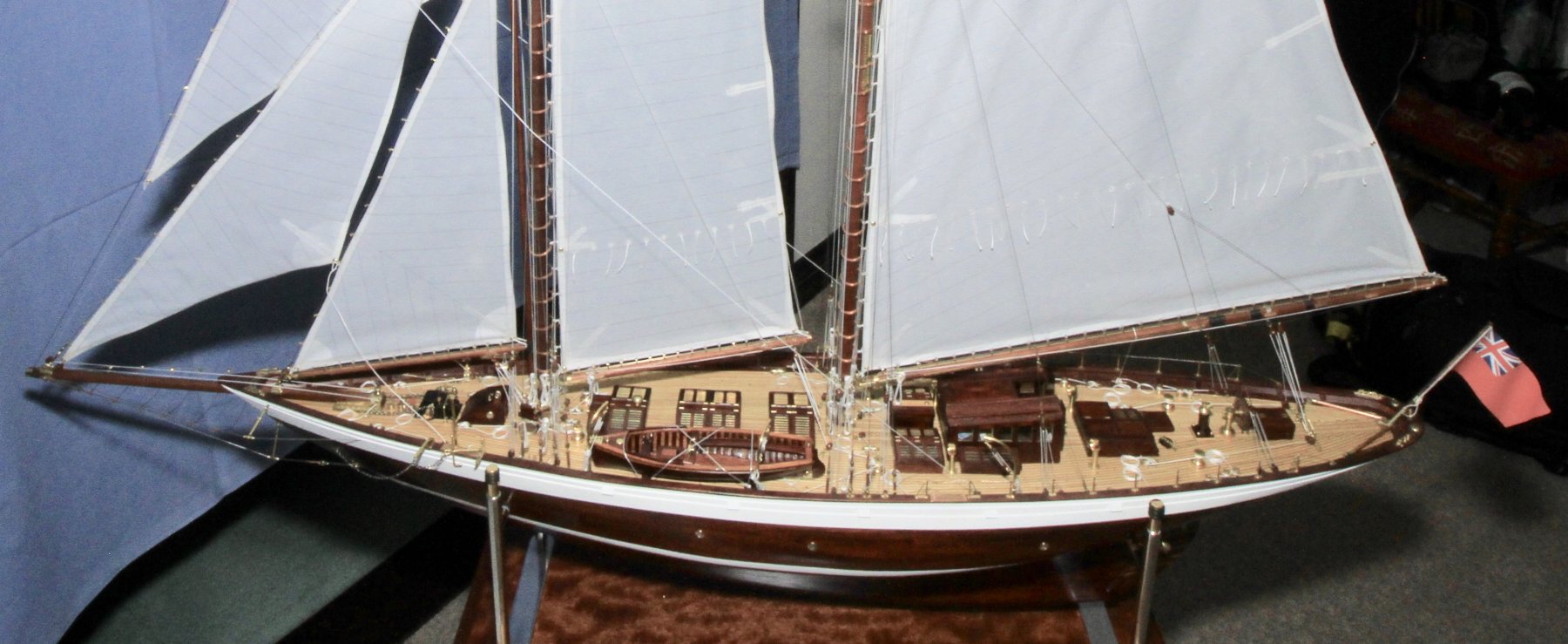
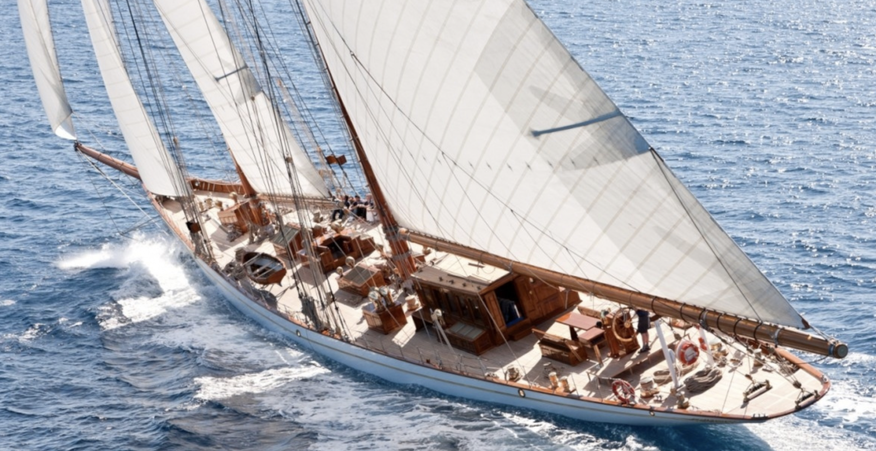
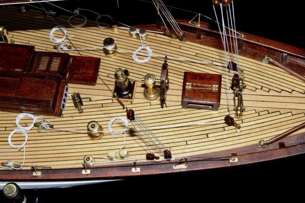
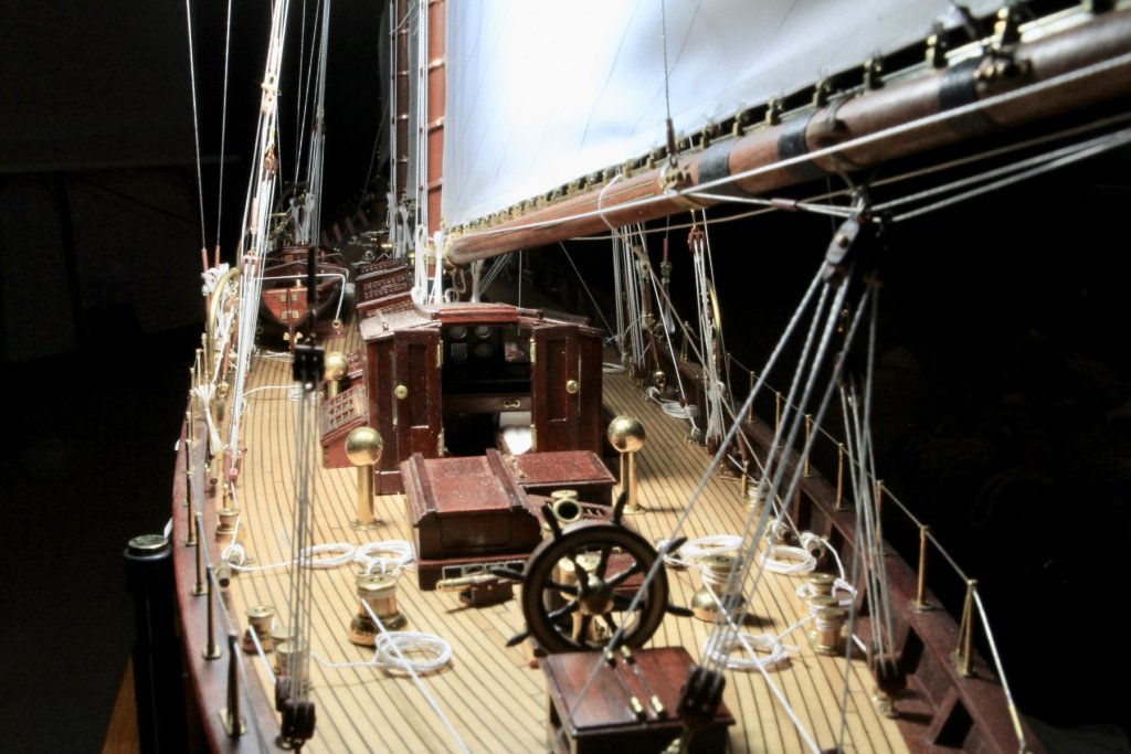
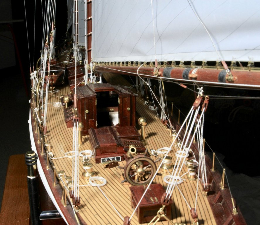
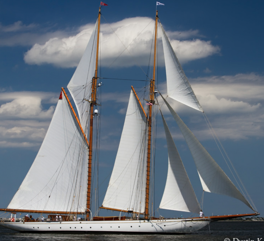
Thank you John / Richard and for your good wishes to my wife. Bedford - she says it is nice to be appreciated by someone. (She must be feeling better as her voice contained a degree of sarchasm). The schooner in the pictures is Germania Nova.
-
Hakan - no but you are quite close. Elena was on the list but I couldn't find the hull lines anywhere.
-
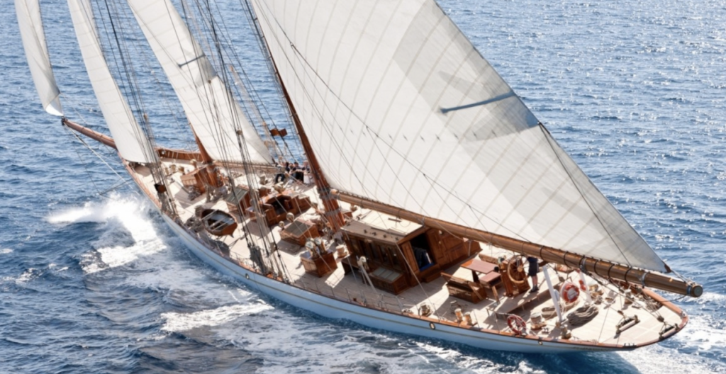
Hakan Thank you for your comments. As to the next build I'm not sure yet but I like schooners and I do quite like this:- At 200ft long she would make a substantial model at 1:36 and I don't want to go smaller as I can manage the detail at this scale. Mark / Bedford - thanks for visiting and your contribution to the off set prop debate. For now model making is off the agenda as my wife has broken her arm to get out of domestic duties. Cooking and washing major in the plan for the next 6 weeks.

-
ancre La Salamandre by tadheus - 1:24
KeithAug replied to tadheus's topic in - Build logs for subjects built 1751 - 1800
The fore deck is now looking really nice Pawel, lovely modelling. She was a very strongly built vessel want she. -
ancre La Salamandre by tadheus - 1:24
KeithAug replied to tadheus's topic in - Build logs for subjects built 1751 - 1800
Lovely detail Pawel. She gets better with every visit. -
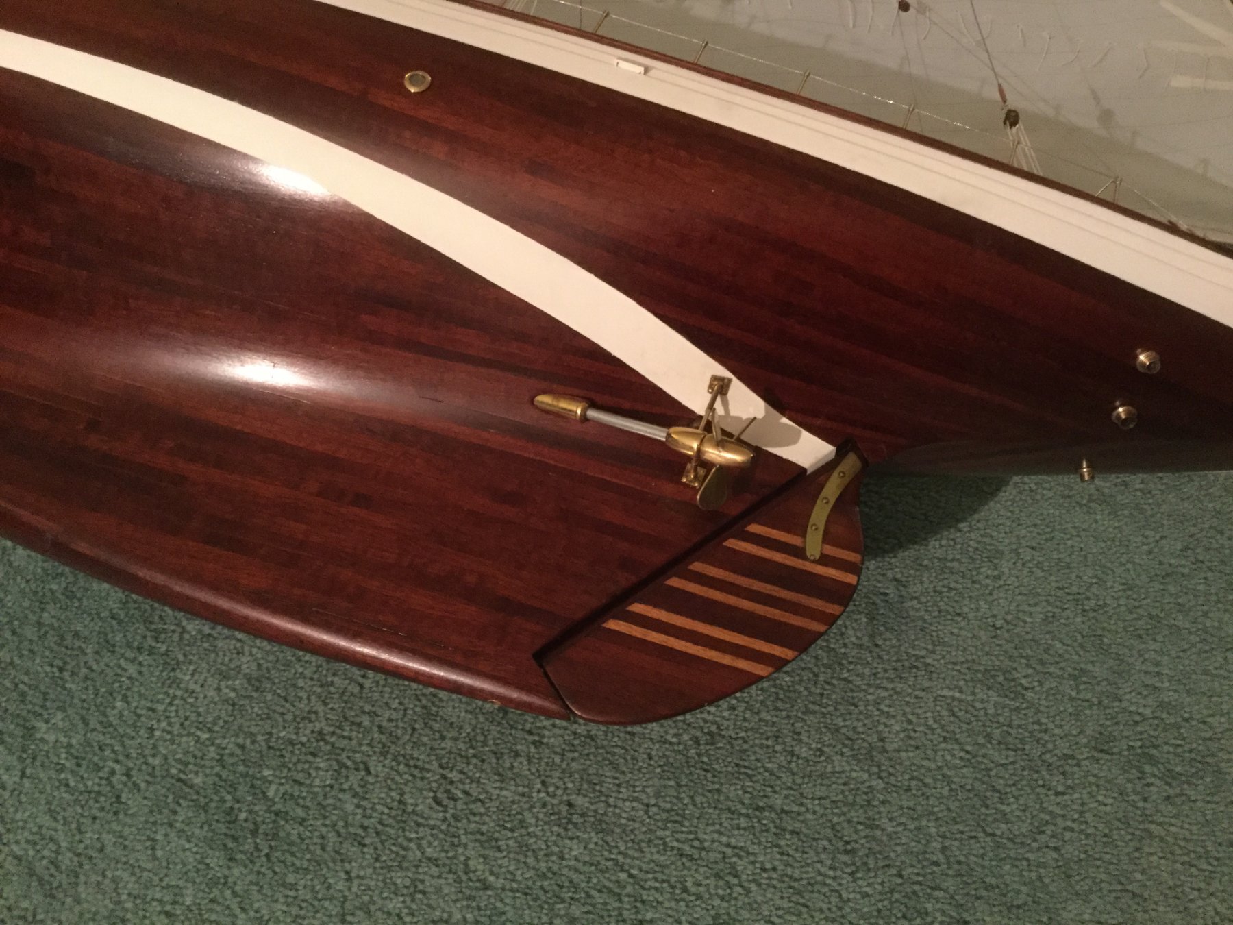
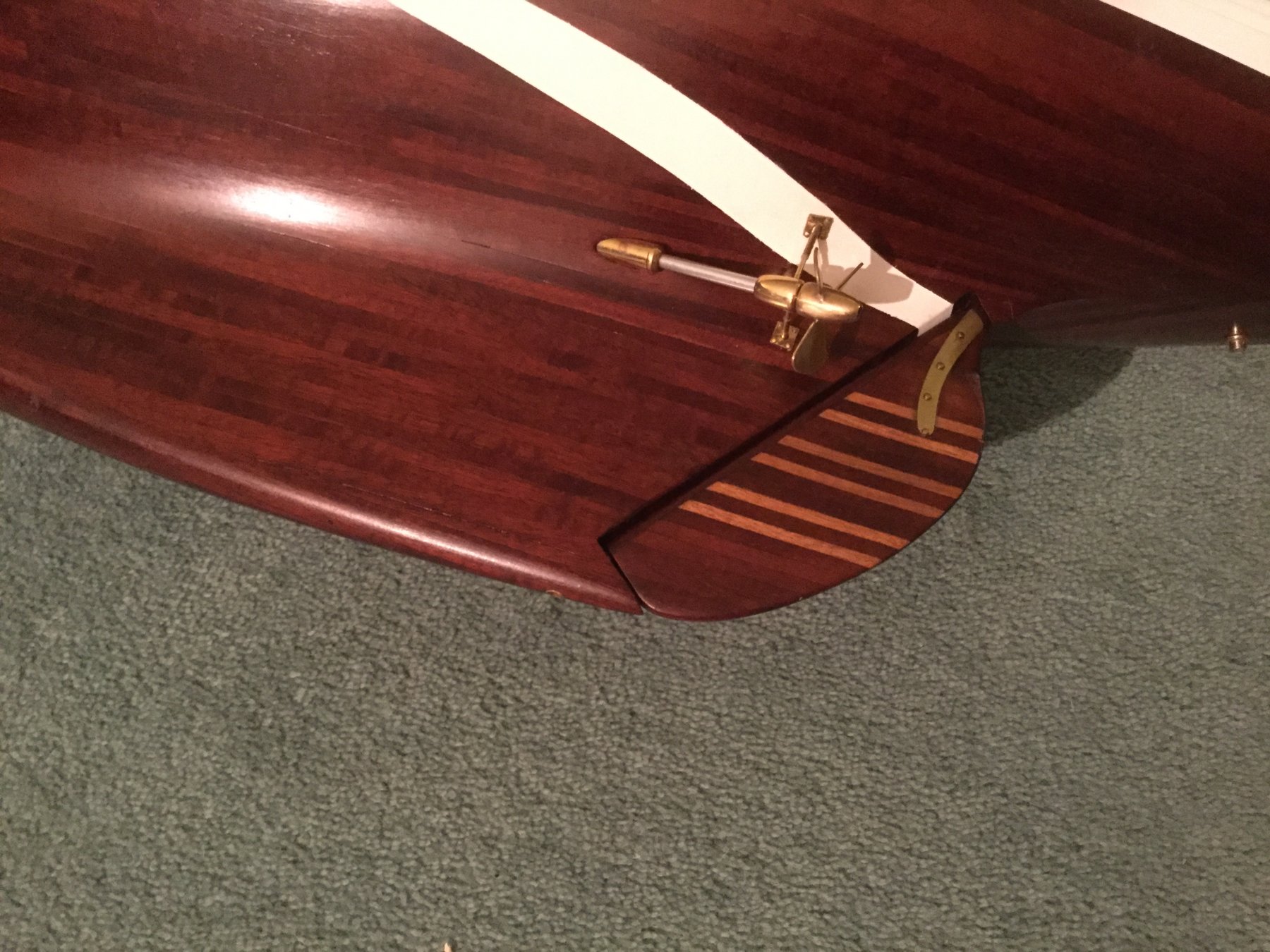
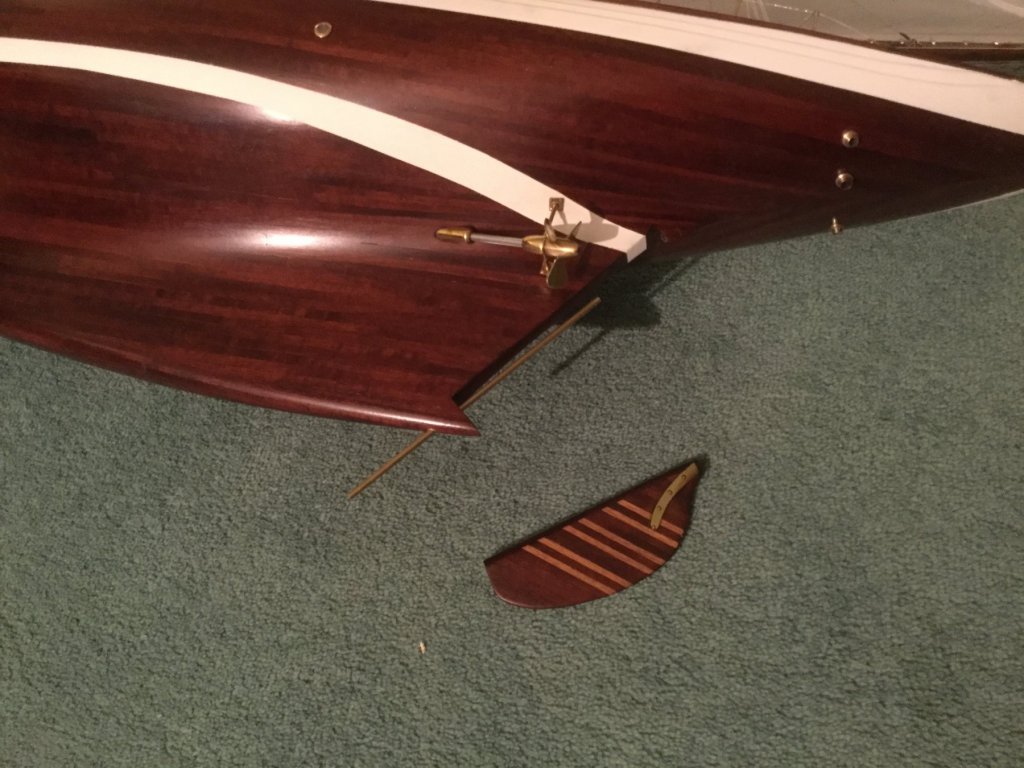
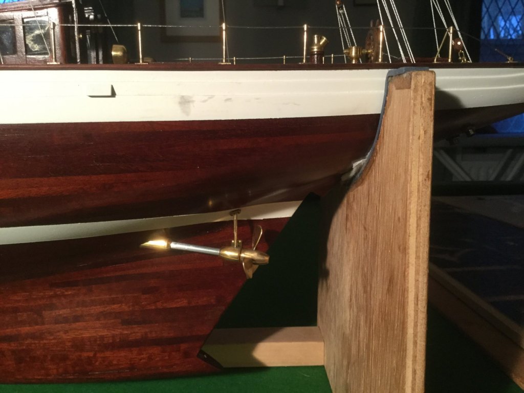
John / Pat - yes I think I will have a dedicated bits box on future builds. The rudder didn't take long to find but I was a bit concerned that it might have gone into the workshop black hole like a couple of other things lately. Thank you for your comments. Thank you Haken / Richard / Druxey - For your comments and support throughout the build. Tom - Maybe its just that memories fade and interest change - but I know what you mean. John - I'm not convinced but it does have few benefits when under engine power. Props produce a component of thrust sideways as well as rearward, (this is usually referred to as prop walk) - depending on the rudder rotation off-setting the prop to port or starboard can compensate for the the prop walk and minimise the amount of rudder needed. It also has mechanical advantages in that the prop shaft can be removed without having to dismantle the rudder. To me it seems like the benefits under power are significantly outweighed by the disadvantages under sail, where it will increase drag and produce diferent sailing characteristics on each tack Also under power the wash over the rudder is significantly reduced which I assume makes slow speed handling a bit problematic. That said all the yachts I have sailed have had axial props, so I don't have personal experience. I bet others will have a better answer???? Thank you for your support throughout the build. When i'm next home I will have a go at a few final photos in the yachts final resting place. My wife has given me permission to have it in the lounge. In the mean time i plan to finish the daughters bathroom.
-
Nice doors Kevin, did you make them?
-
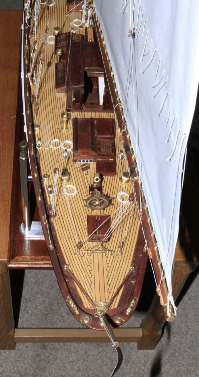
I had a good rummage through my cupboards and thankfully located the rudder and it’s shaft. A few minutes later and it was fitted. Direction re-established!!


- 882 replies
-
- 25
-
-
Pat, Dan, Tom and Bedford - thank you all for your supportive comments. Today I was looking at the yacht thinking “that’s it” when I noticed the obvious omission. Sometimes in life we lose the big picture in all that detail and end up rudderless. I made the rudder in September 2016, now I just have to find it.
-
Always a pleasure to catch up with your description Dan
- 287 replies
-
- 2
-
-
- michelangelo
- ocean liner
- (and 1 more)
-
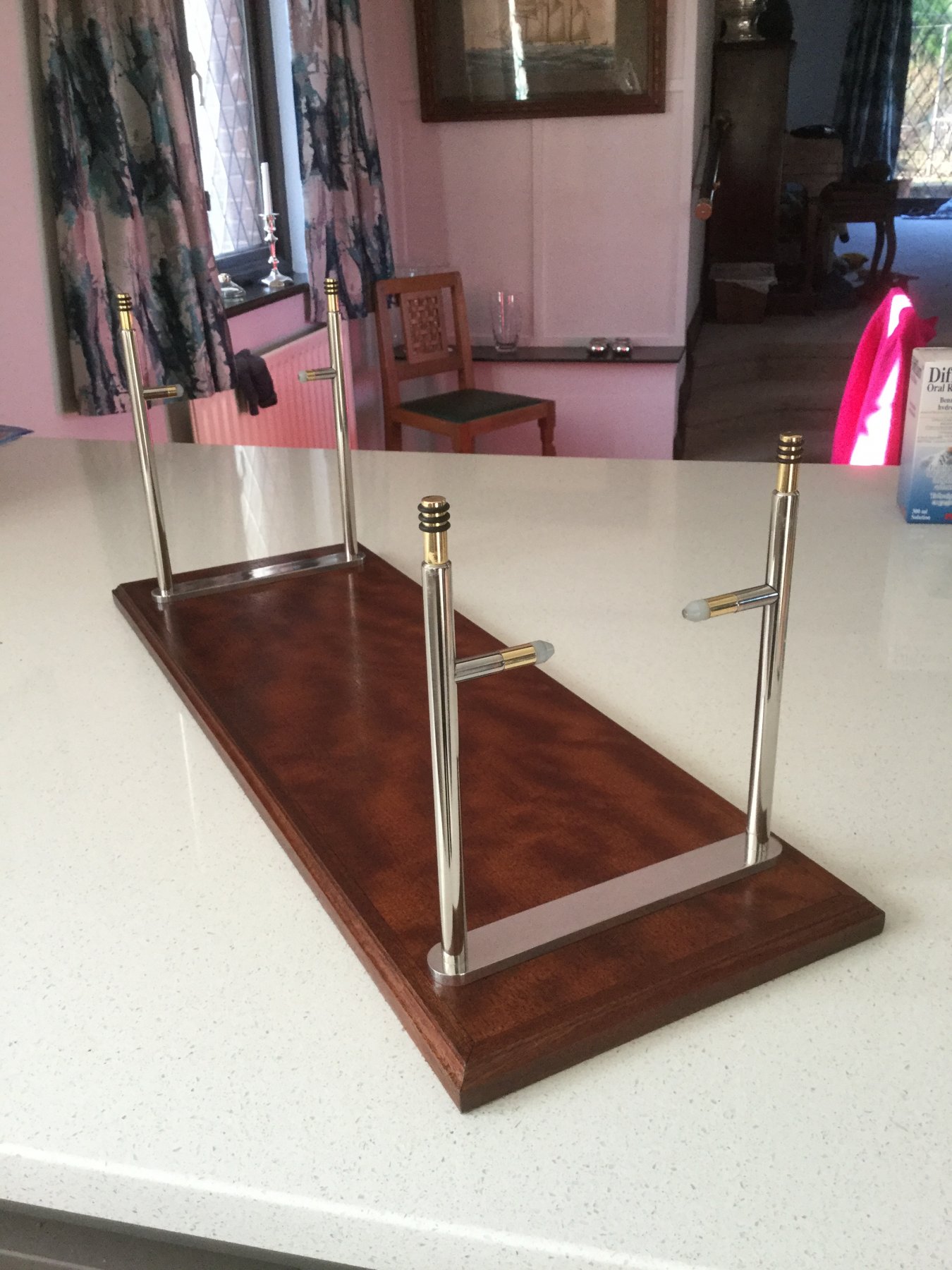
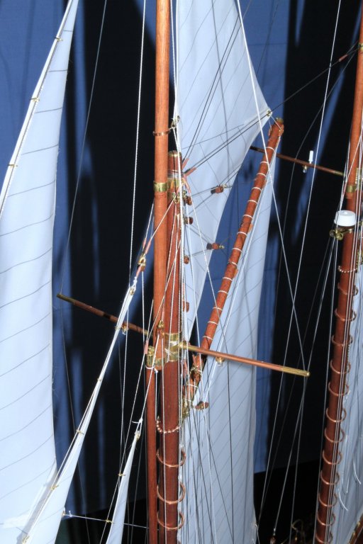
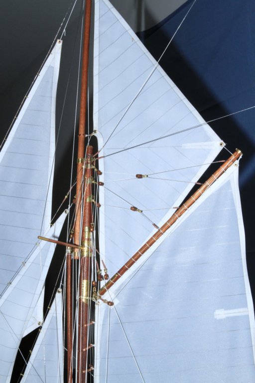
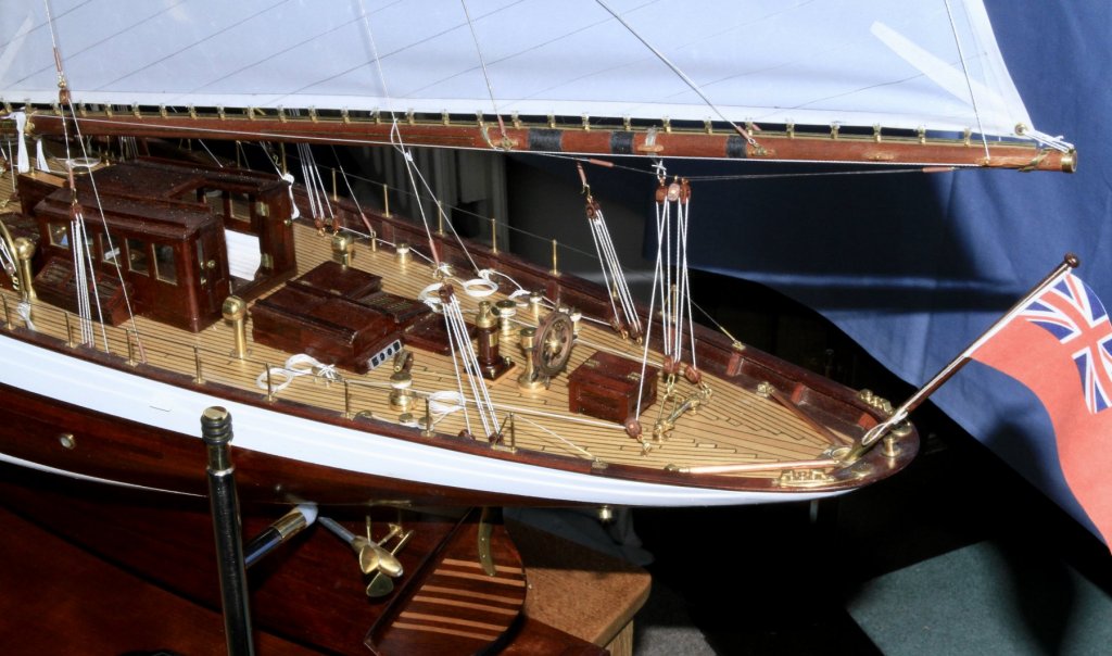
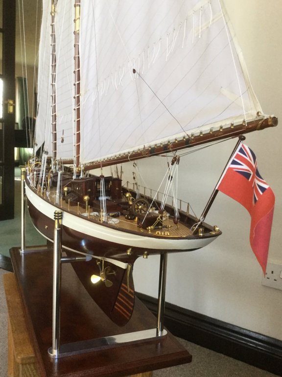
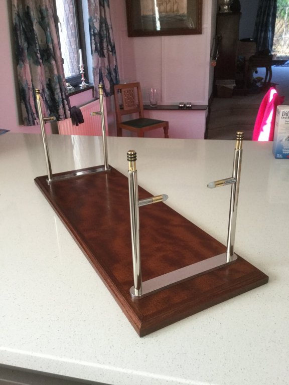
I really must crack on and get this build finished. At least I have had time to finish the display stand. It took some time to trim the front legs to get Altair to sit with her waterline level. Now all that’s left to do is make and mount the ensign and the Royal Thames Yacht Club flag. Oh and replace 3 stays that have loosened as the model has acclimatised to the house conditions. I must catch up on other people’s logs before I get withdrawal symptoms.
-
Hi Brunelrussell - If you look at my Altair Build - top of page 20, this is an option for making a dome.
-
Hello Mozatman, nice to see you have taken the plunge into ship modelling. MSW is a great resource and if you need it you will get a lot of encouragement and advice. Start a log so that we can all enjoy your journey.
-
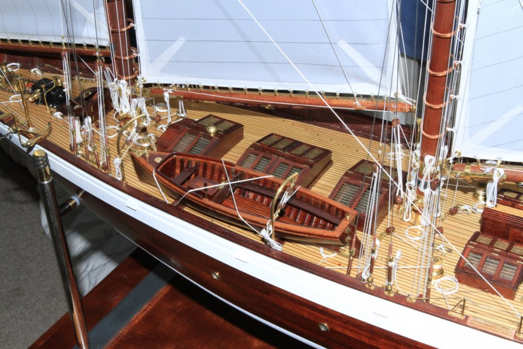
Haken, Pat, Richard, Mark. thank you all very much for your kind comments. Michael, an interesting thought. The only photograph I have is one of the smaller dingy strapped to the deck. Here the straps seem to be of webbing. To carry off the leather idea the leather needs to be very thin and i know of a source as my wife is addicted to fine leather gloves. She is also apt to lose one every now and again so next time she does I may do the upgrade. No boat progress this week although I have ripped out tiles, rebuilt walls, plumbed in sinks and radiators, and laid 140 sq ft of ceramic tiles. My daughter is pleased.