HOLIDAY DONATION DRIVE - SUPPORT MSW - DO YOUR PART TO KEEP THIS GREAT FORUM GOING! (89 donations so far out of 49,000 members - C'mon guys!)
×


KeithAug
-
Posts
3,979 -
Joined
-
Last visited
Content Type
Profiles
Forums
Gallery
Events
Everything posted by KeithAug
-
 Hello Paul Brave having 2 on the go at the same time. I find more than one stresses me out.
 -
Mike There's nowt ere that tha can't do with a bit of elbow grease an nouce. Rimember "it's better to fettle an shaht abaht it nor nivver to fettle at all". Looking forard t yer build log. P.S. - i'm not really from Sussex.
-
Fantastic job on steering gear and light. Very impressive. What is silkablock and where do you get it?
-
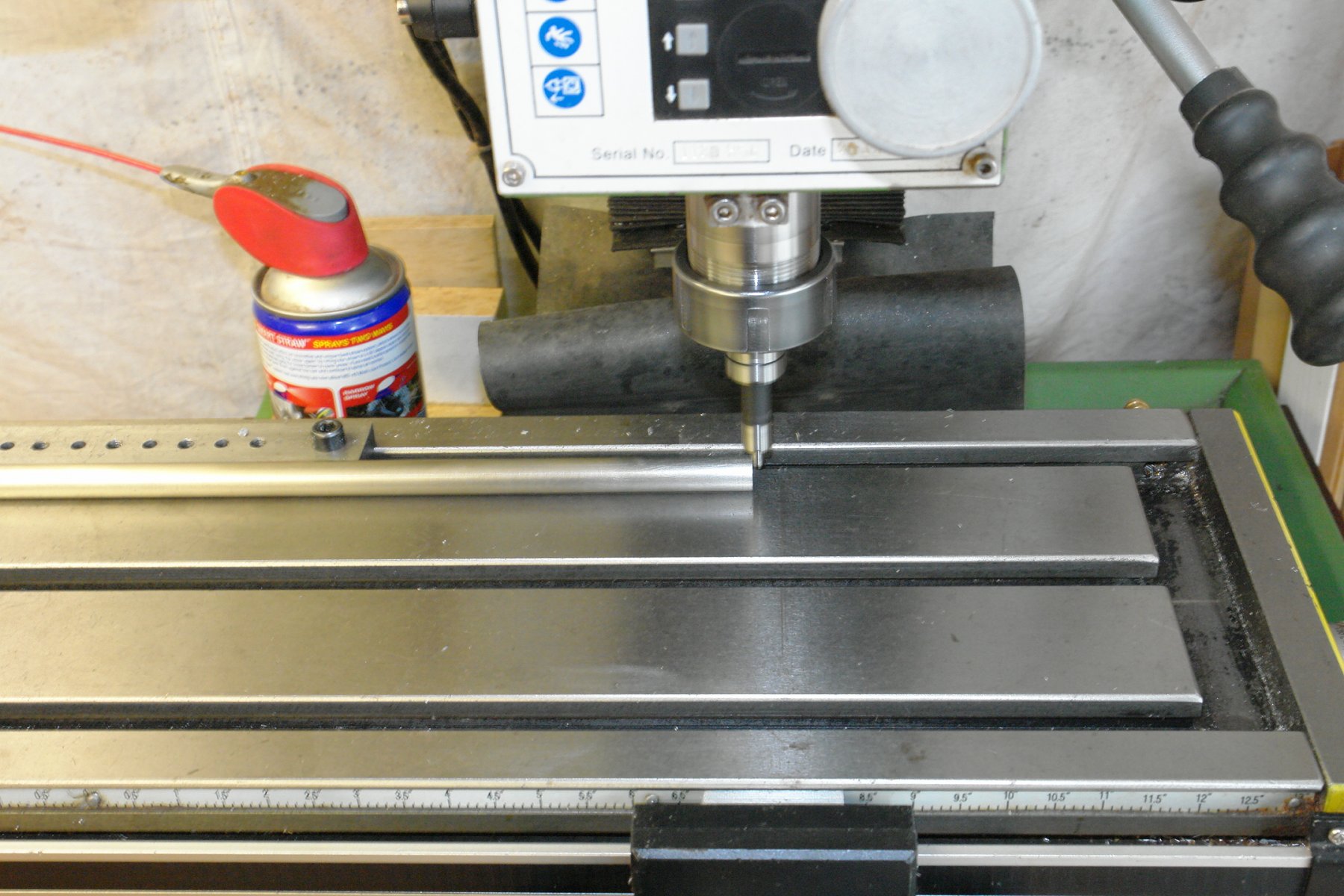
Hello Wefalck When I started my apprenticeship in the late 1960s we had never heard of edge finders. The method then was to wet a piece of cigarette paper and stick it on the edge. Then with the milling cutter rotating, wind the edge slowly towards the cutter. Just before the cutter touches the edge it wipes the paper away, thus establishing the position of the edge to less than the thickness of the paper, typically better than .001 inches. I now use a mechanical edge finder, but I may go back to how I learned to do it a half a century ago.
-
I'm being silly - i should just buy an electronic edge finder and eliminate the problem - Provided I can find one small enough!.
-
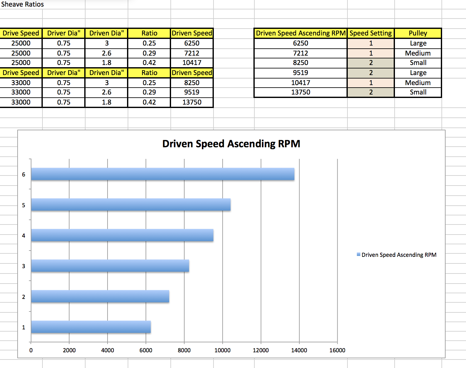
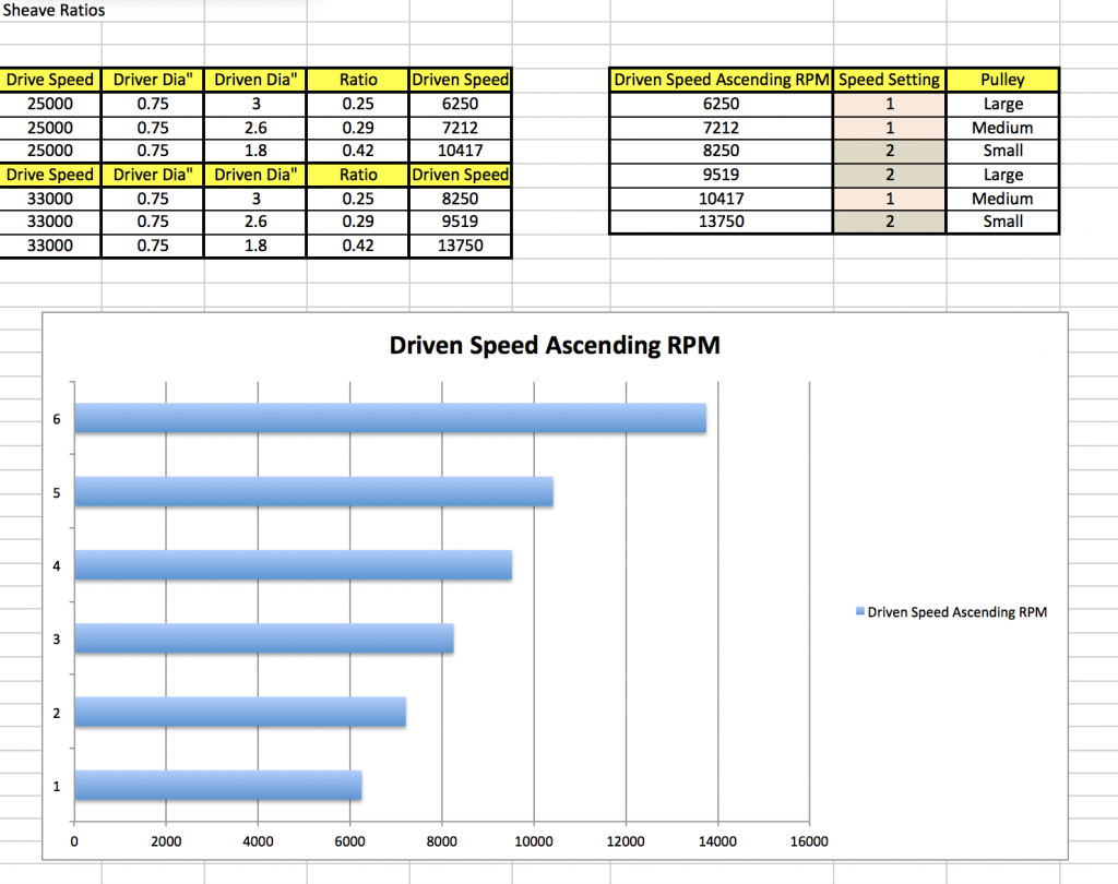
Derek / Wefalck - thank you. Being away from the workshop at the moment I am having withdrawal symptoms. It has however given me time to have a bit of a think about the drive arrangement. I have found it very difficult to get much information about the rotozip drive motor. The only information I have is what is on the body - i.e. 550W / 220v and switchable 25000 / 33000 rpm. The ratio of the speeds is almost exactly 1 to 0.75. I am therefore assuming that the motor is an AC synchronous motor with stator pole switching. This being the case I'm a bit concerned about the choice of variable speed drive - I guess I need to have the views of an electrical engineer. Views welcome?????????????? In the mean time however I have decided to put up with the limitations of the rotozip and deal with the speeds via a 3 pulley belt drive. With 2 motor speeds this gives me a total of 6 speed settings. Because I am working with the fixed ratio of motor speeds (1 to 0.75 as explained above) the speed choice is little compromised. However i think the following should be workable:- The pulley sizes are sensible at 0.75" driver and 3", 2.6" and 1.8" driven. I feel fairly comfortable with a cutter speed range between 6250 and 1375 rpm. I would however like a very low speed - circa 500 - 1000 rpm for use with a mechanical edge finder. Therefore I may come back to the VSD option at some time.
-
Derek, nice ship but glad whaling ships no longer find a use. Quite a gruesome business.
-
Gunter - it’s a bit time consuming but my preferred method is covered in my Altair build (bottom of page 2 and then on to page 3) klick on the link below my name to find it.
-
Modrock plaster of Paris bandage works really well for landscapes. Much used by railway modelers. It’s easily shaped, sets quickly and produces a realistic scale finish worth bearing in mind if you have a future need. It would cover the foam really well. Love the build.
-
Very good small models Javier. I look forward to seeing more of your work. Your translation is good.
-
Jon, Your journey is nicely informative. It’s probably a bit late for this build but one good option for gap filling is to collect very fine sanding dust from the same wood as the hull planks. Mix this with PVA wood glue diluted 2 PVA to 1 water and then use the paste as a filler. Leave to dry and then sand the hull. The result is usually slightly darker than the parent wood but tones in well. Good progress by the way. I should add that others invented the sawdust trick well before I reinvented it.
-
Thank you Michael. Before the next one I have deviated into the world of metal cutting - I got round to making the 3rd hand before taking on a milling machine. It will probably be a few months before Germania starts to take shape. And thank you to everyone who has followed the build, with or without comment.
-
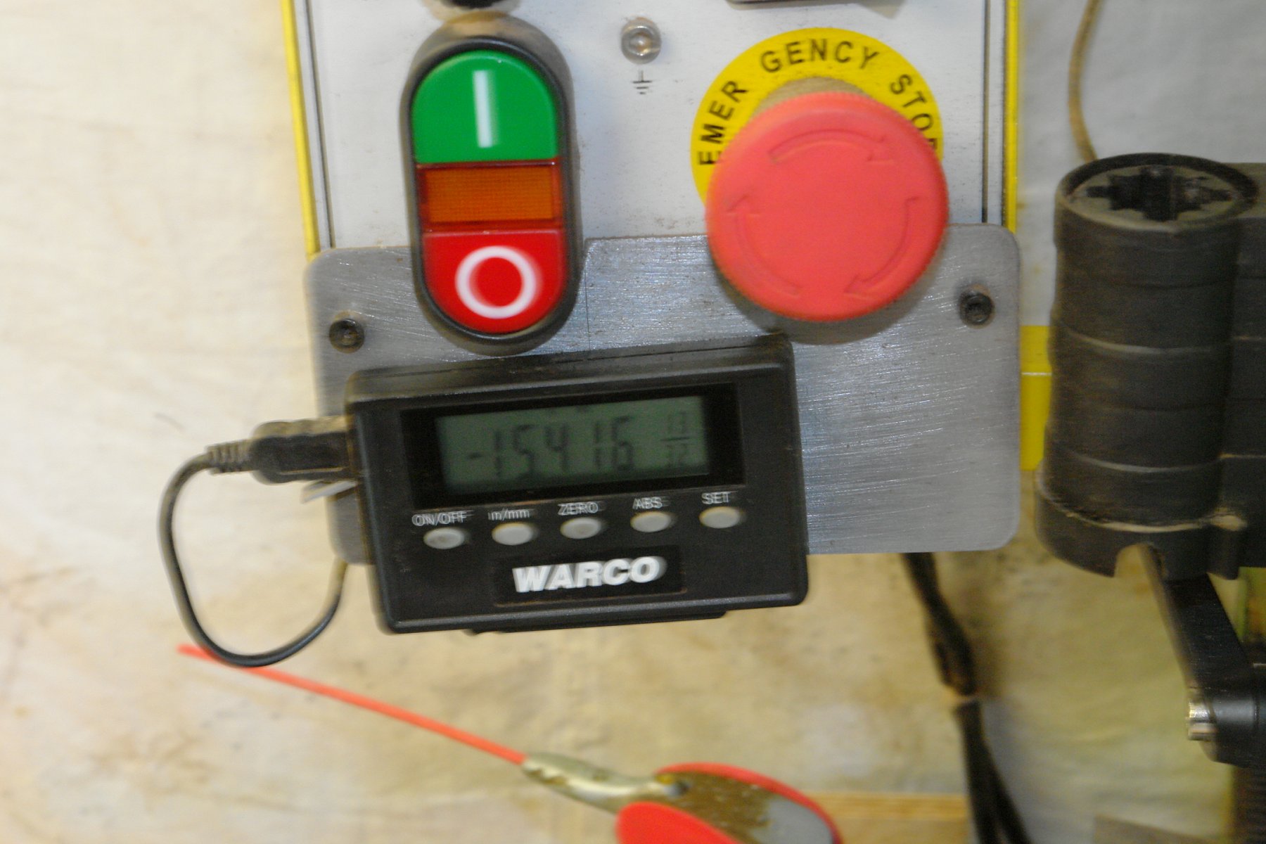
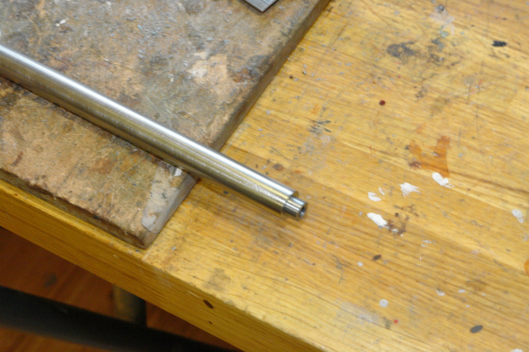
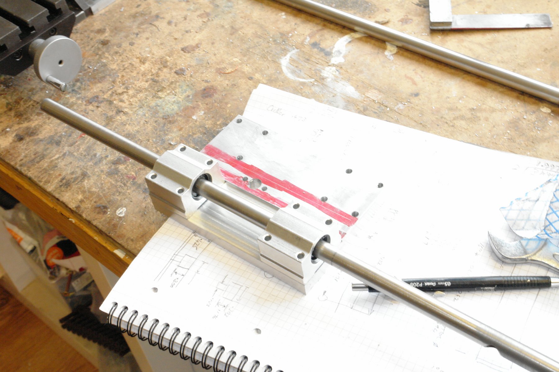
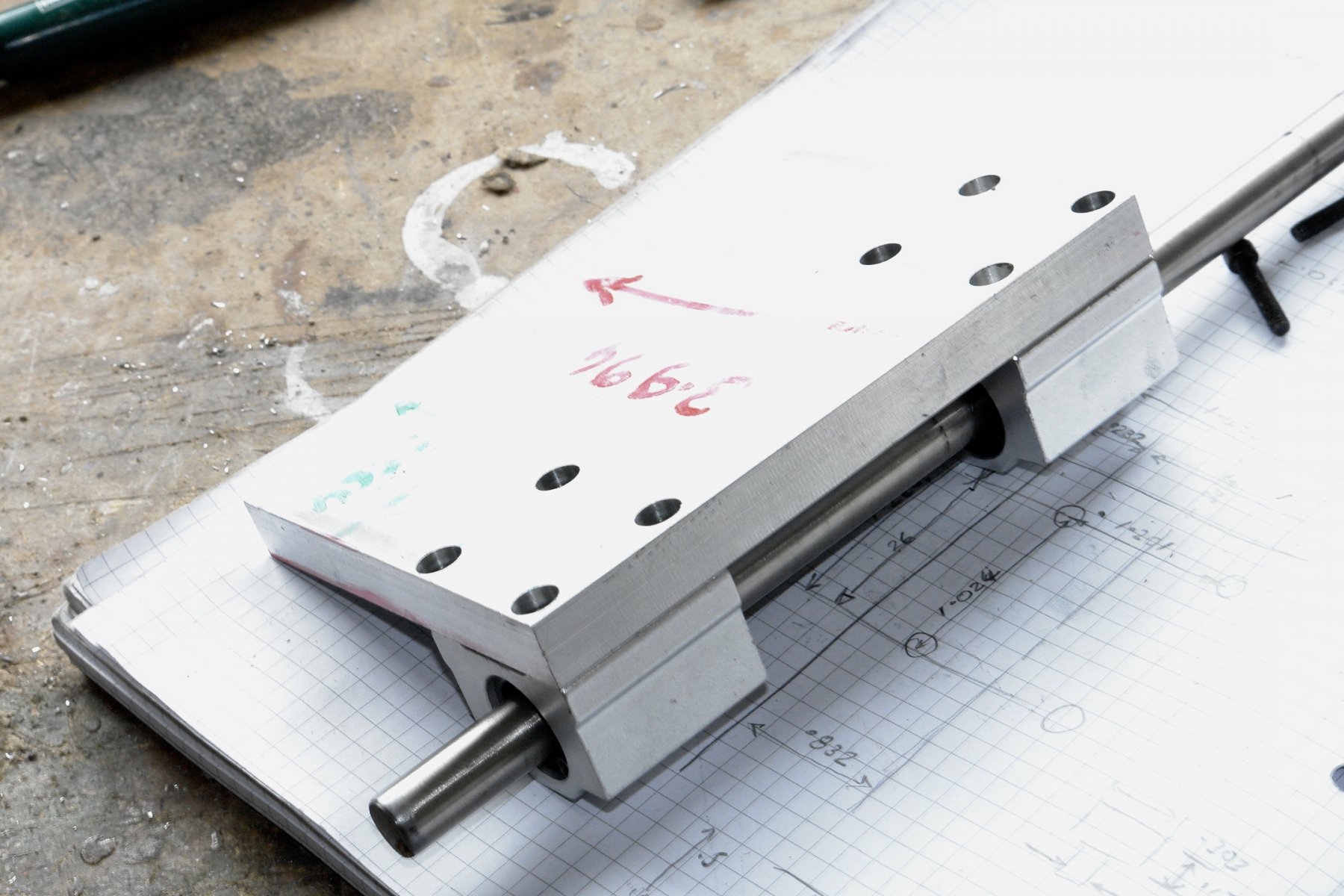
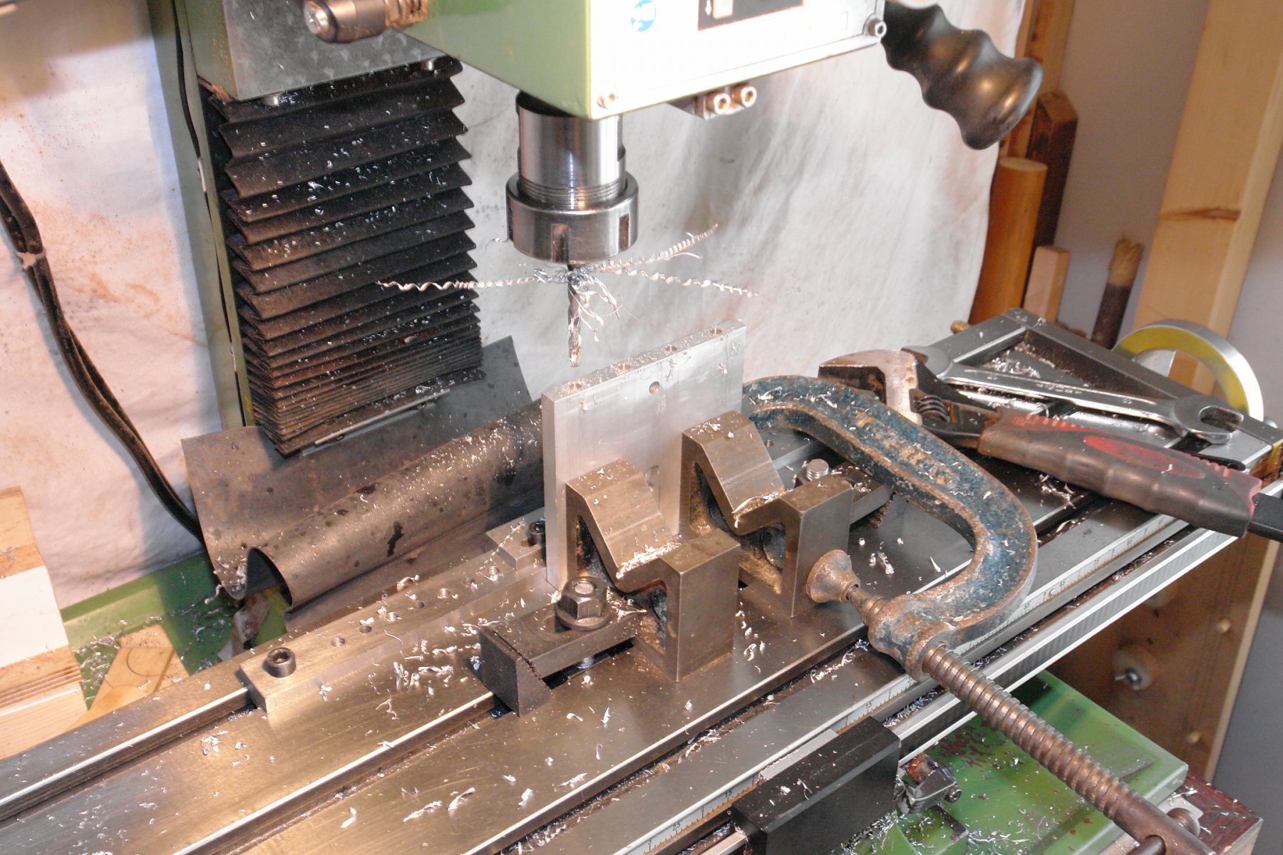
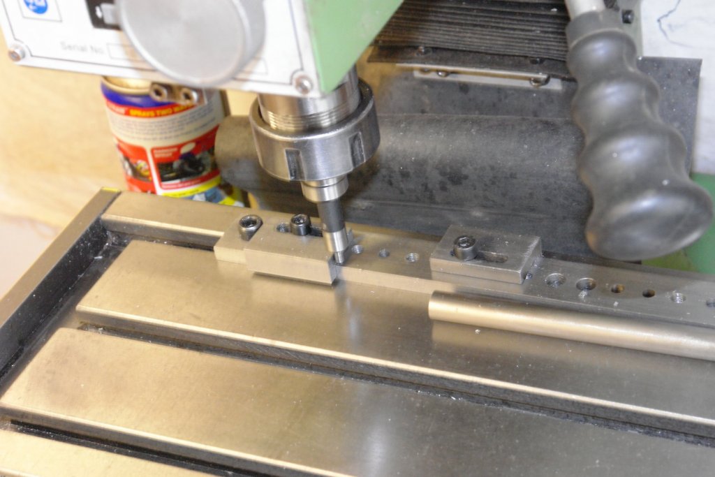
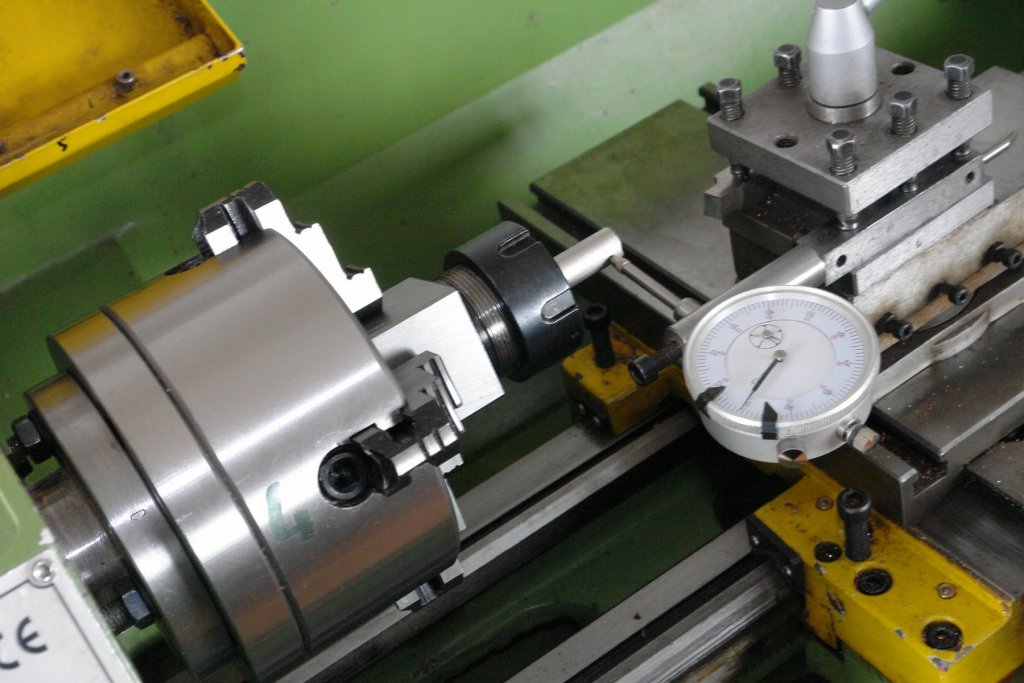
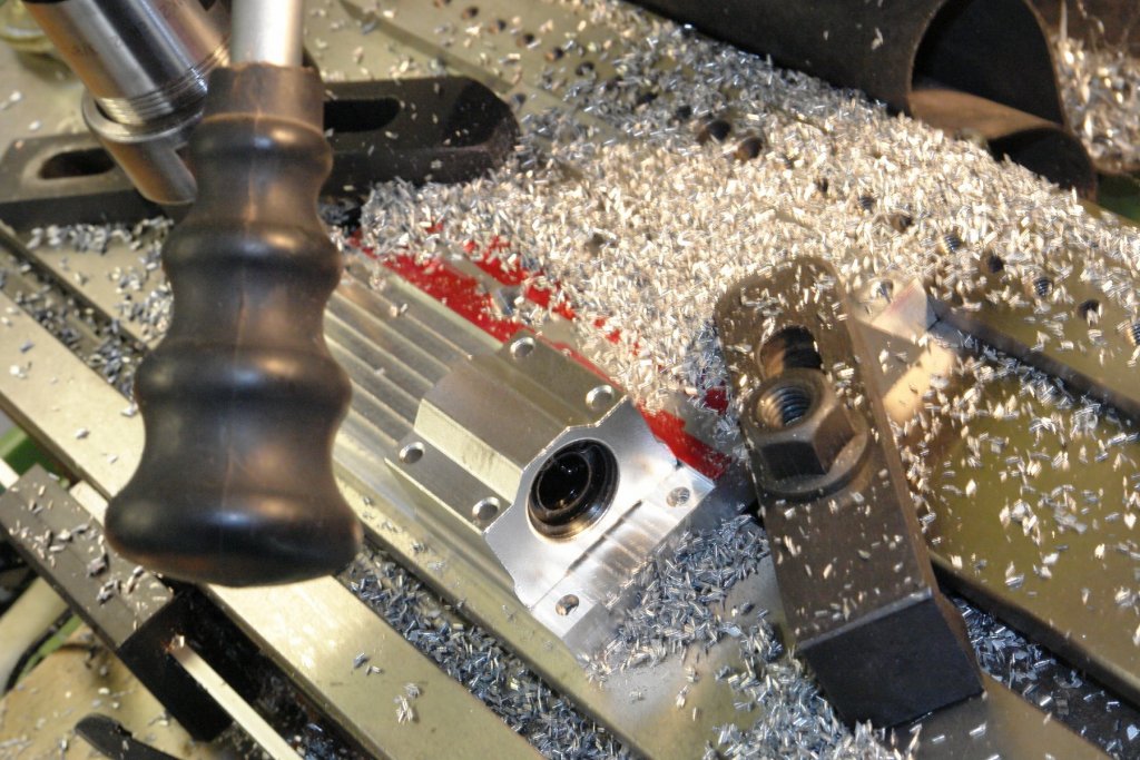
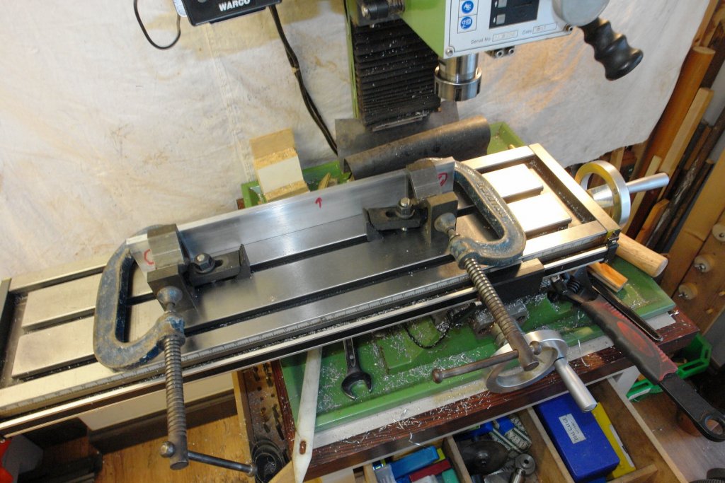
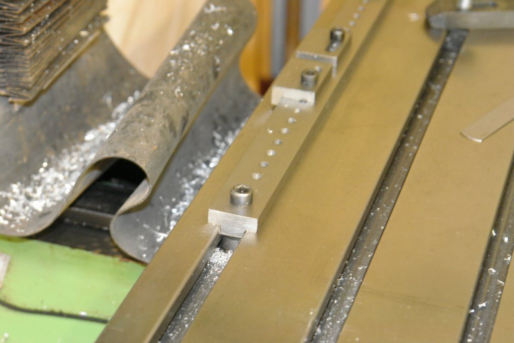
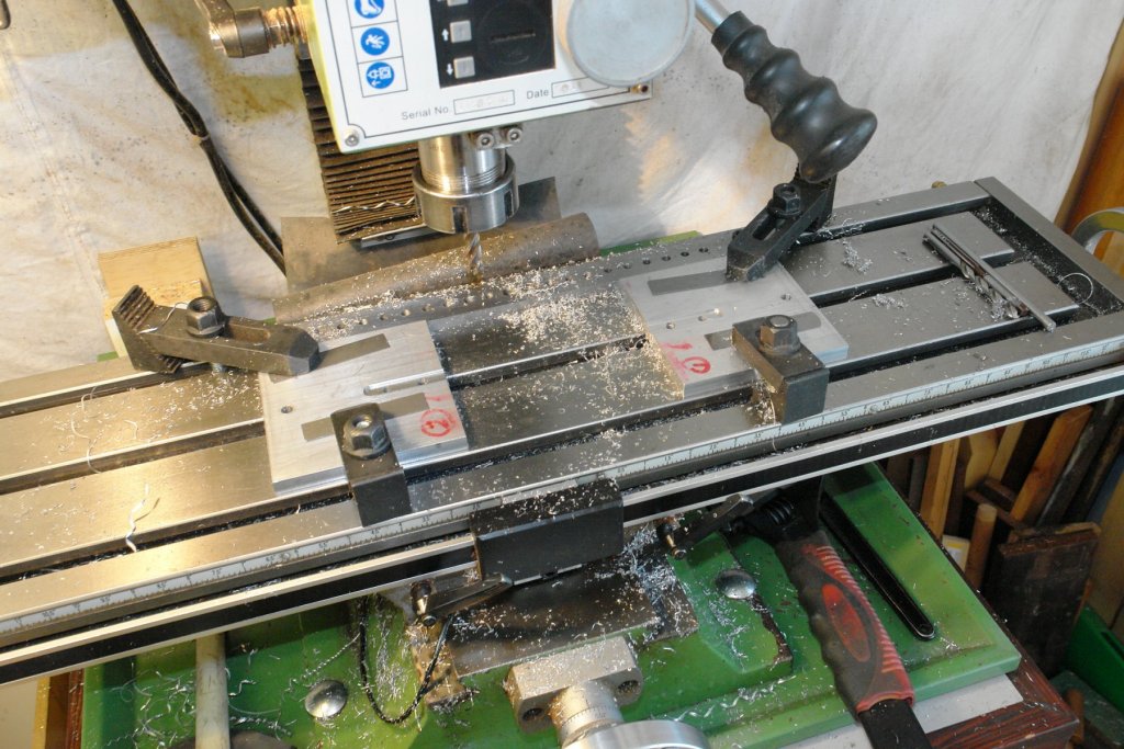
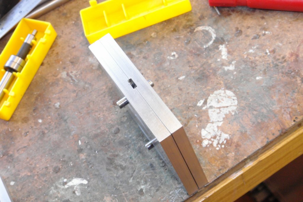
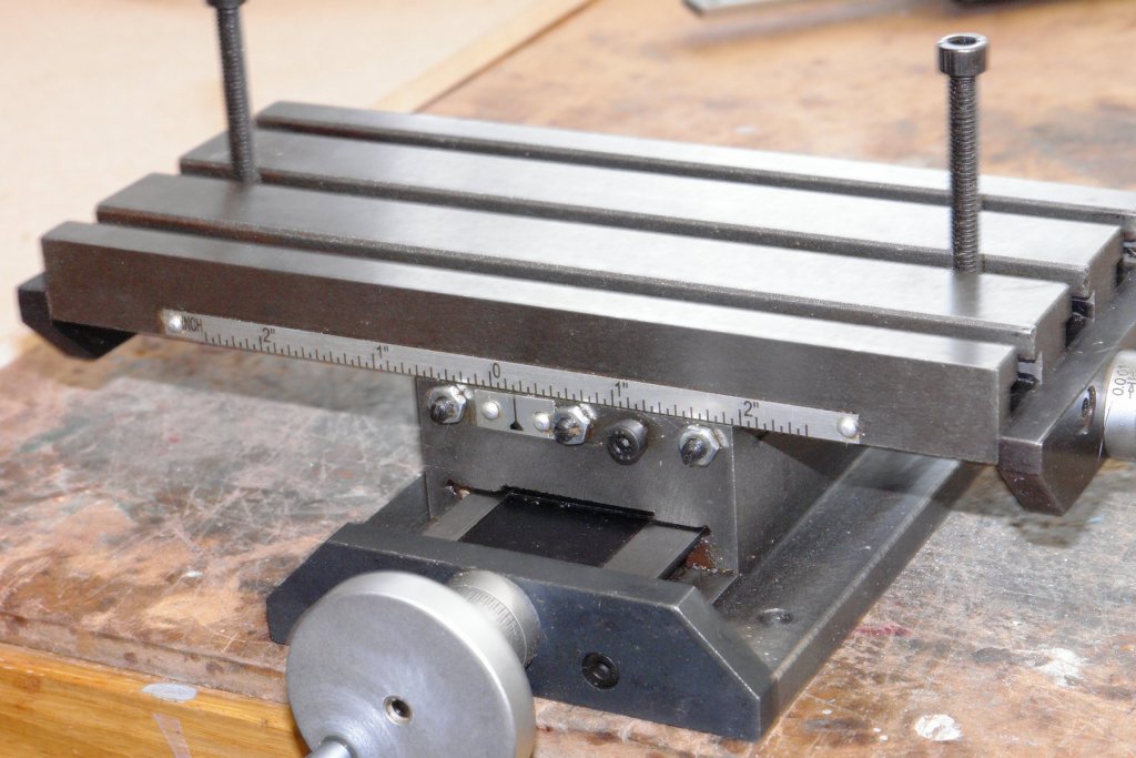
So the final bit of building for s few weeks. The running bars have to exactly match the back plate - i.e 15.000" across the shoulders. The difficulty is I don't have a vernier that long, however as they say "necessity is the mother of invention. I started by turning the bars over length as measured with an engineers rule. My only accurate measuring device was the milling bed y axis - graduated on the hand wheel and fitted with a DRO. The first step in measuring was to place an end stop on the parallel location bar mentioned earlier. The position of the end stop was then fixed with the edge finder. The DRO and the hand wheel graduations were set to zero. The bar was pushed up hard against the stop and then the edge finder was used to fix the other end of the bar. One bar was 15.416" long while the other was slightly shorter at 15.406". The shoulders on either end therefore needed to be .208" and .203" respectively. It was critical that the shoulders on the bars were cut concentric, so rather than relying on lathe chuck accuracy I used a collet block in the 4 Jaw chuck. This allowed me play with the accuracy of the set up of the bars to my hearts content. Using the dial gauge I set the running of the bars at circa .0005 or better before cutting each of the 4 ends. The shoulder diameter was .314" +/- .00025" to match the drilled and reamed holes in the end plates. The ends of the bars were drilled and tapped M5 to take the fixing bolts. The test of all my efforts at accuracy was in the assembly. Phew! - it turned out OK. IMG_0399.MOV


- 62 replies
-
- 11
-

-
Good to see you back Michael - its always worrying when old timers disappear for a while!!!!.
- 749 replies
-
- 4
-
-
- albertic
- ocean liner
- (and 2 more)
-
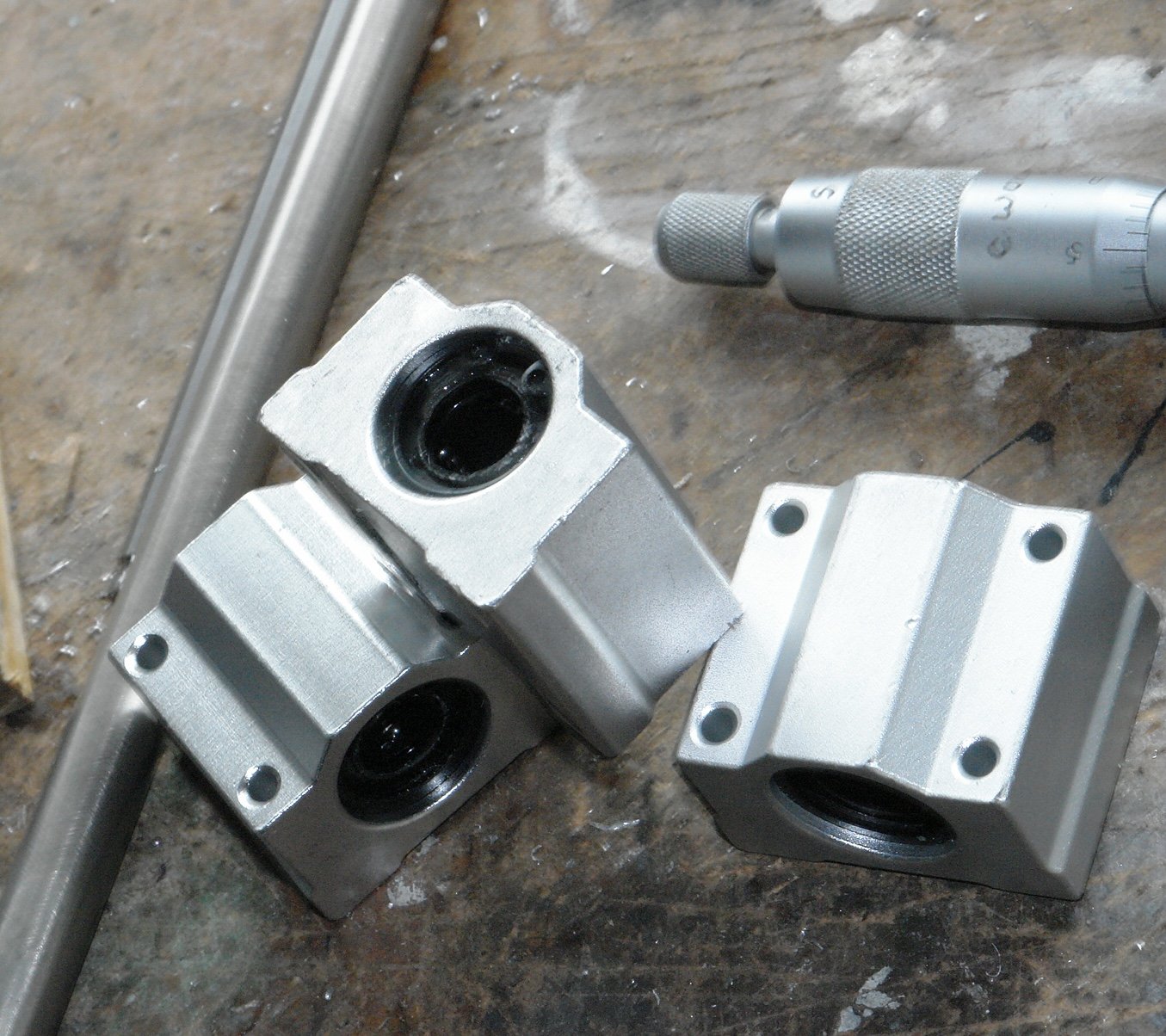
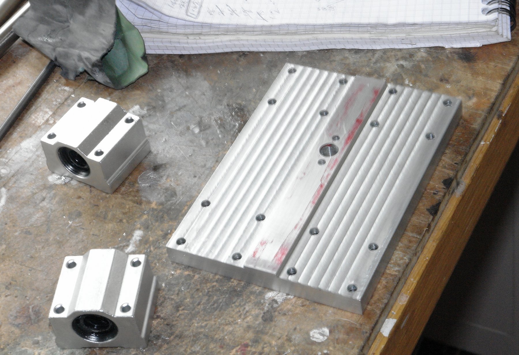
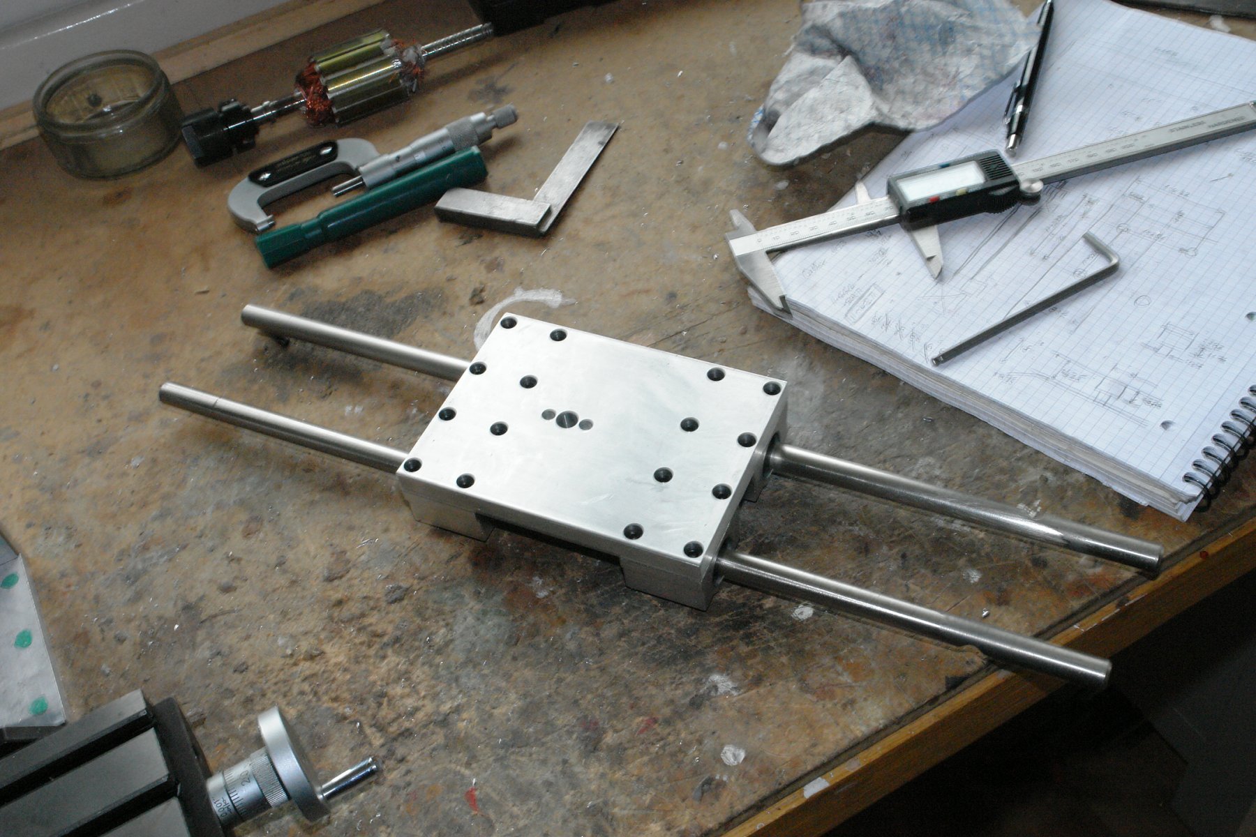
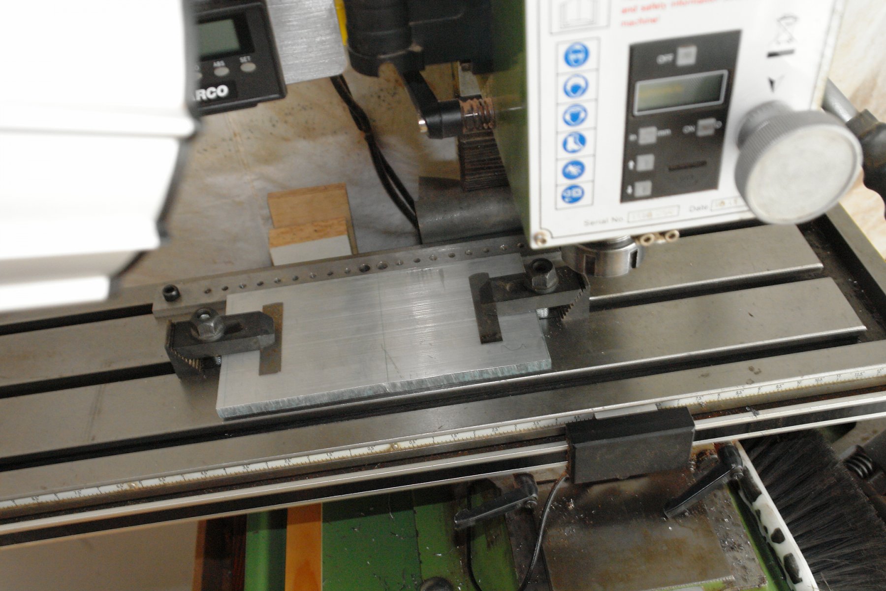
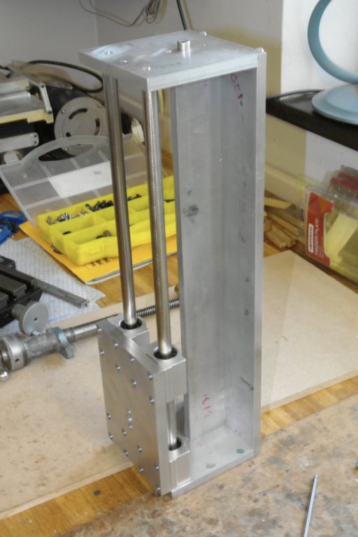
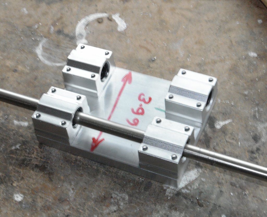
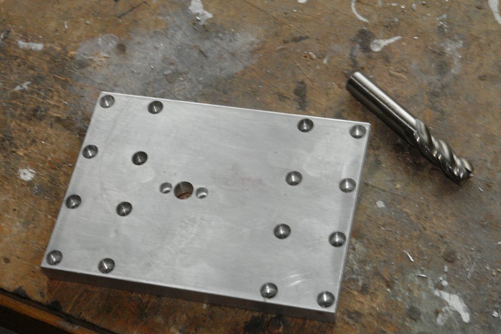
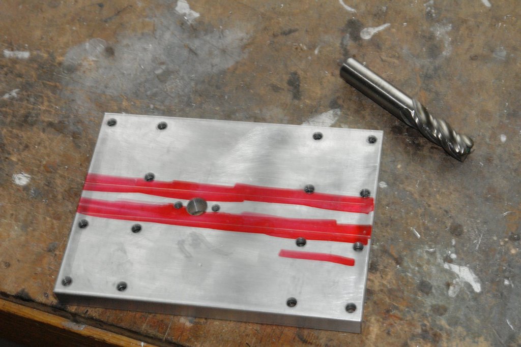
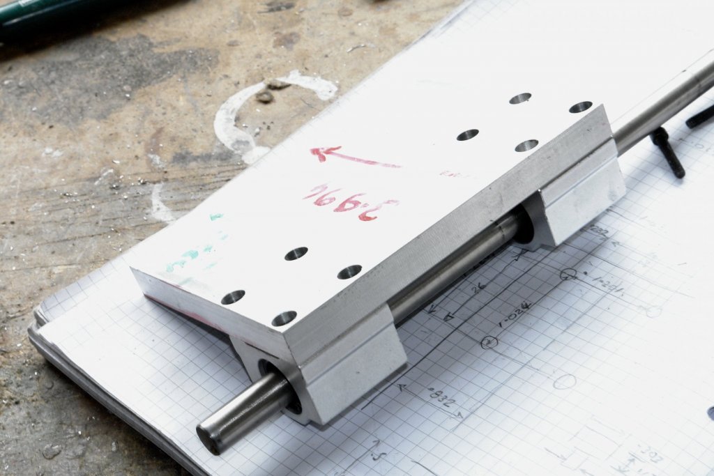
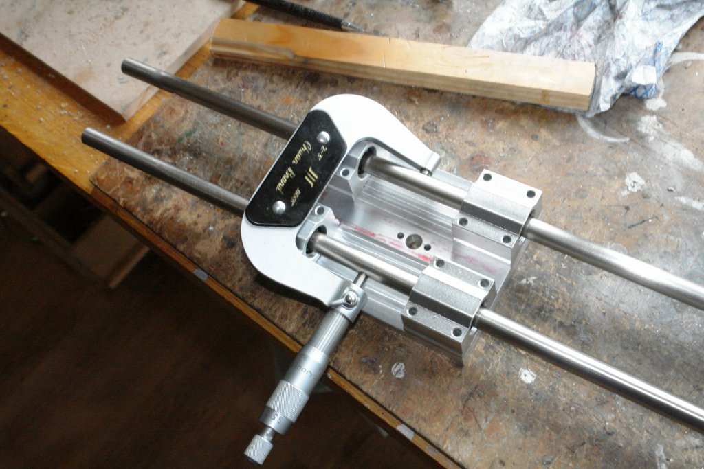
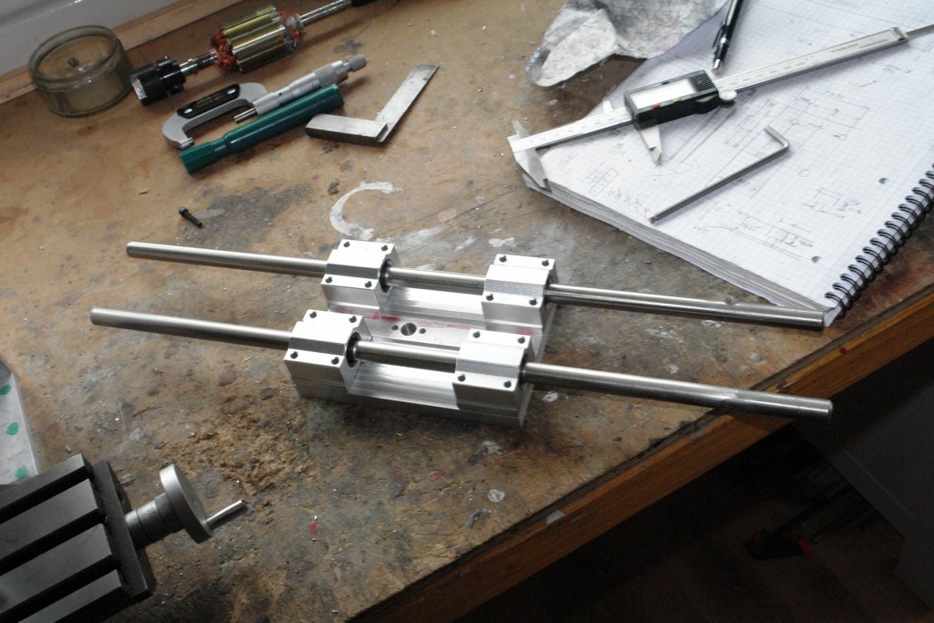
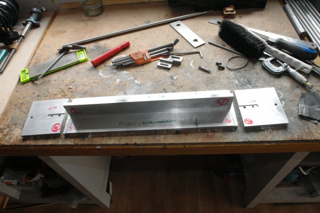
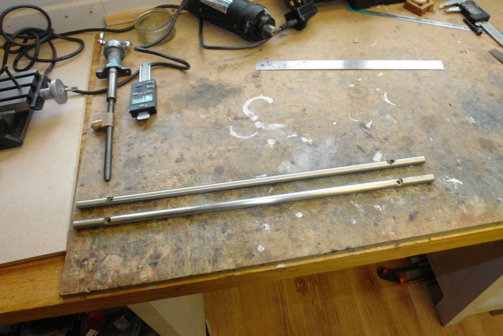
A bit more progress to report - but the workshop will be little visited in the coming 2 weeks as other priorities loom. A couple of days ago the linear bearings turned up at the door - I paid £9 for the four. They are sold for CNC router builds. I cut the .500" plate that the bearings are seated on. I chose quite a wide spacing to maximise the vertical movement accuracy of the mill. In the following photo the bearings are resting on the plate with a bar (ex kitchen door handle) threaded through. The bar is surprisingly accurate and fitted the 12mm bearing bore with no discernible play. The bearing plate was then accurately drilled with the 16 holes to take the M5 bearing fixing bolts. The holes were countersunk to take the cap screw heads. The central 3 holes are for attaching the boss that will take the lead screw nut for the vertical movement. The bearings are recessed against a machined shoulder to ensure vertical alignment. This was marked purely as a check for next machining stage. The bearings were then bolted in position and the running bars reintroduced. The end plates have to be very accurately machined to take the running bars as any discrepancy on the separation distance will mean that the bearing plate will jam. I therefore measured the outside of the assembled bars and their diameter and calculated the centre dimension. The end plates were then drilled and reamed to this dimension.


-
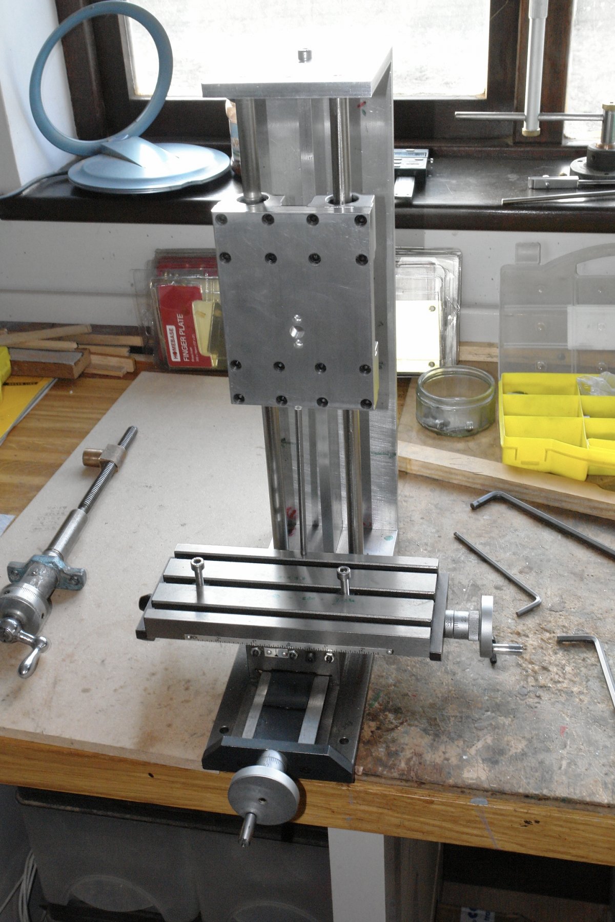
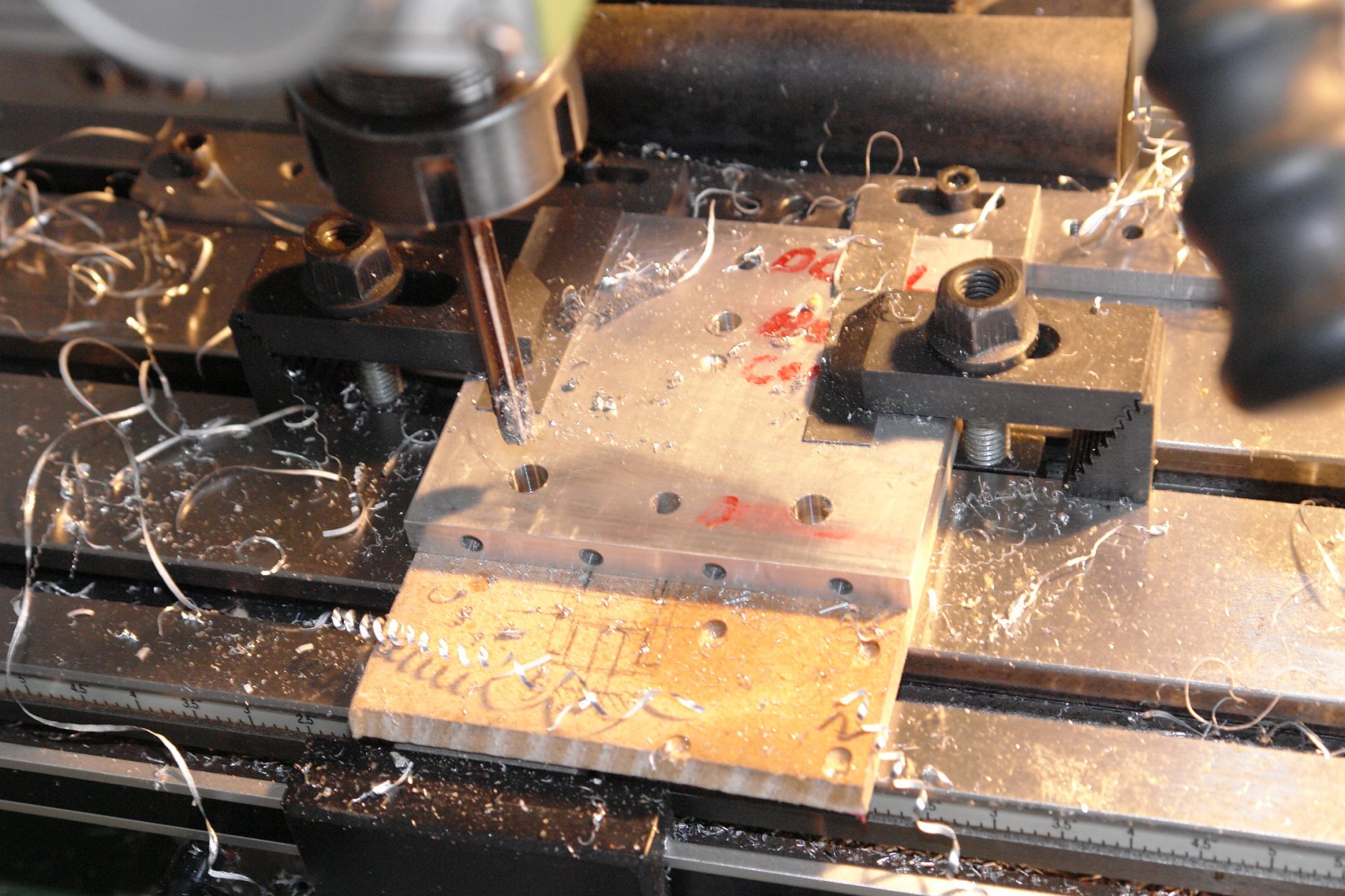
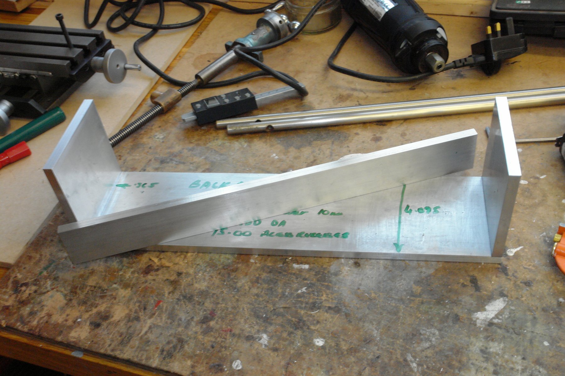
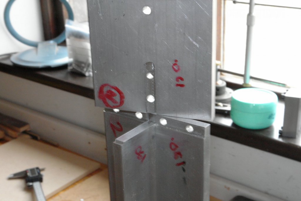
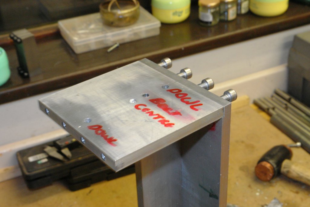
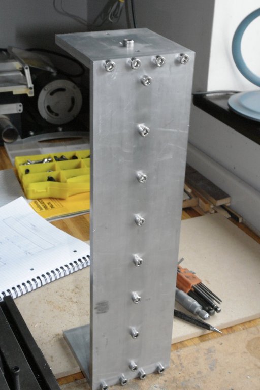
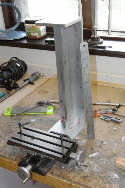
Thank You Bob. I made a bit more progress yesterday - mostly drilling and tapping. The top plates and the web needed drilling and then tapping along the edges. To hold them in position they were clamped agains the square edges of a pair of "V" blocks which in turn were clamped to the milling table. Some time later all was drilled and tapped. I mentioned earlier about making sure the axis of the column was truly at right angles to the base. To ensure this the two end plates have centre drill holes accurately machined in identical positions. These will be used to mount the entire column assembly between centres in the lathe so that the base can be skimmed square with the axis. The 4 components - end plates, web and back plate were bolted up to test fit.

-
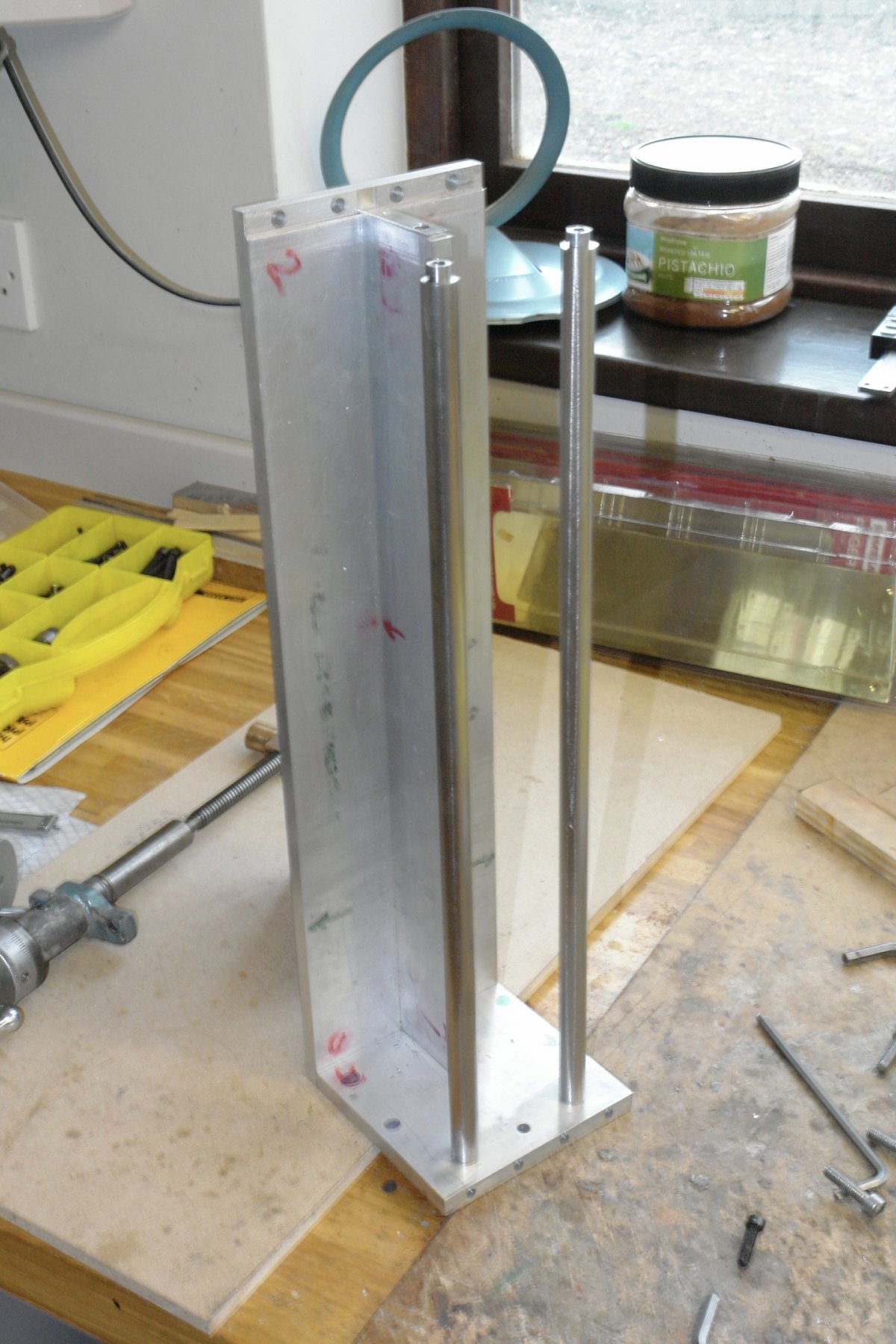
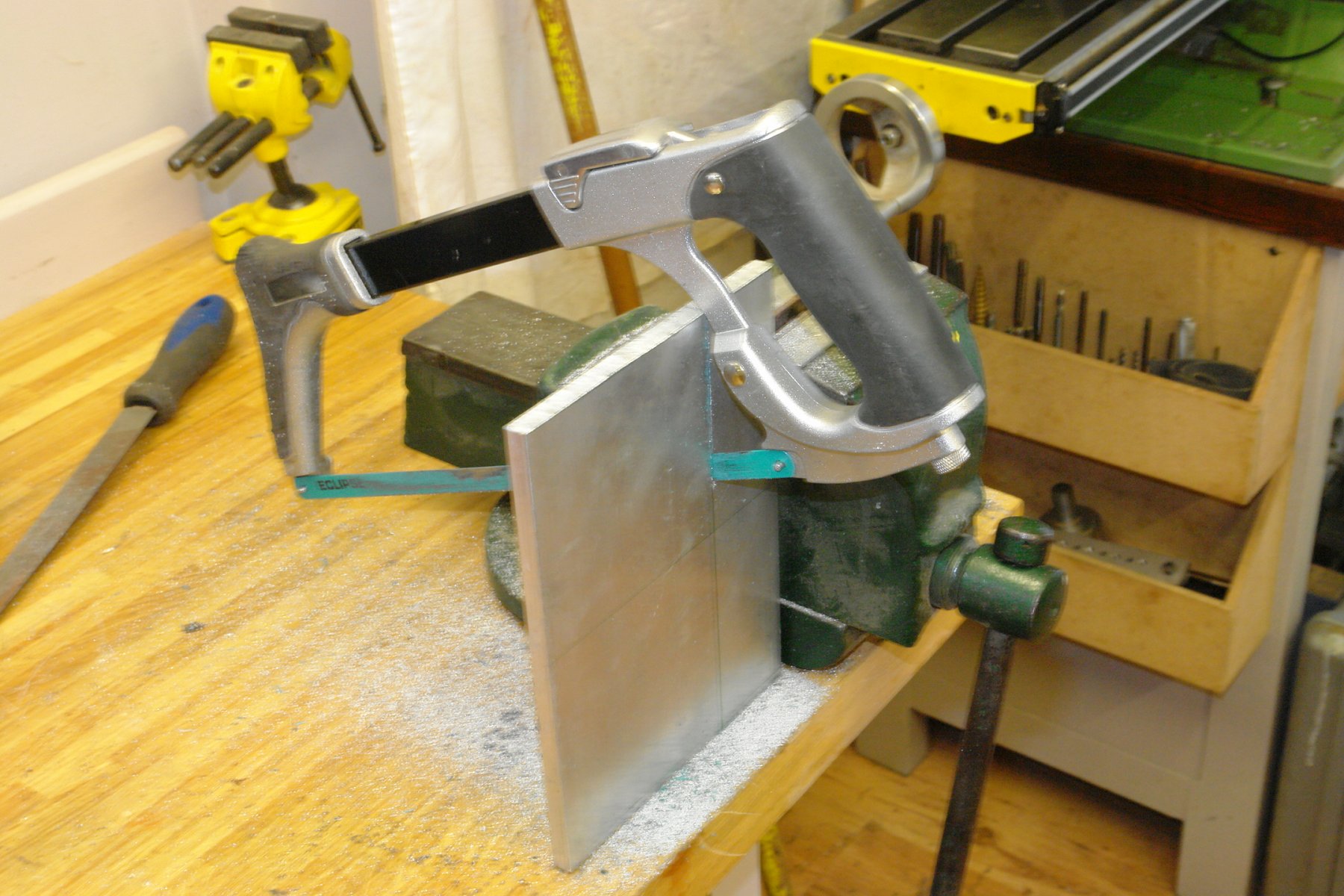
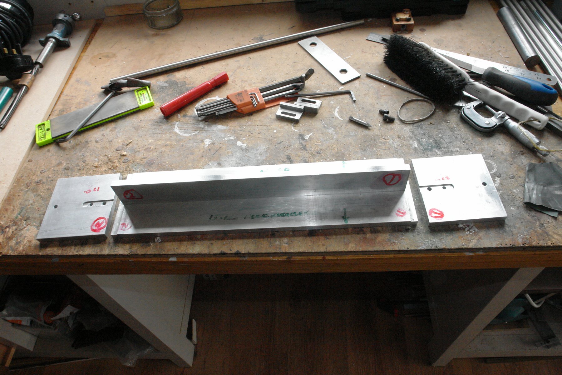
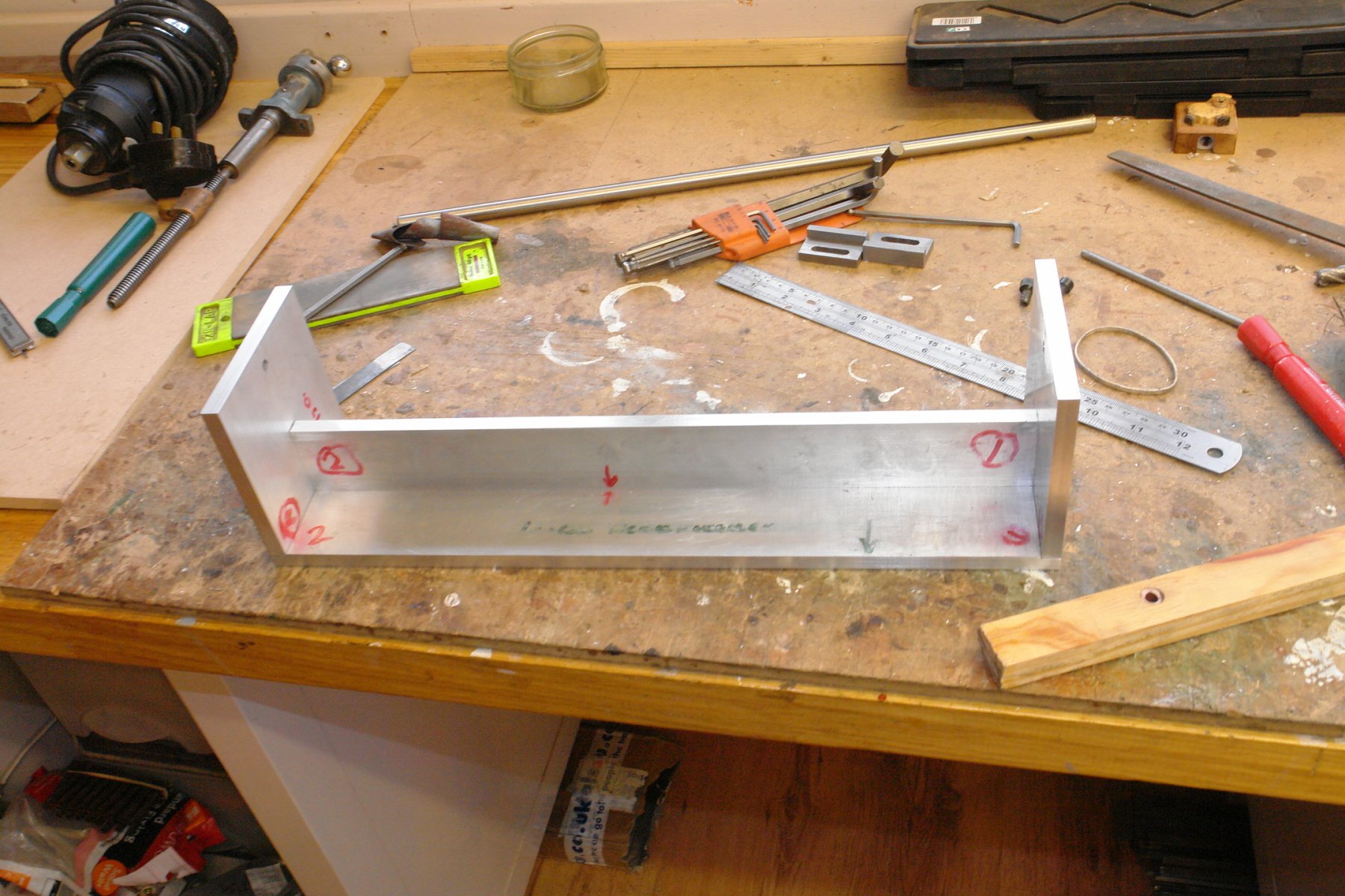
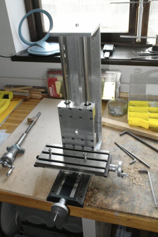
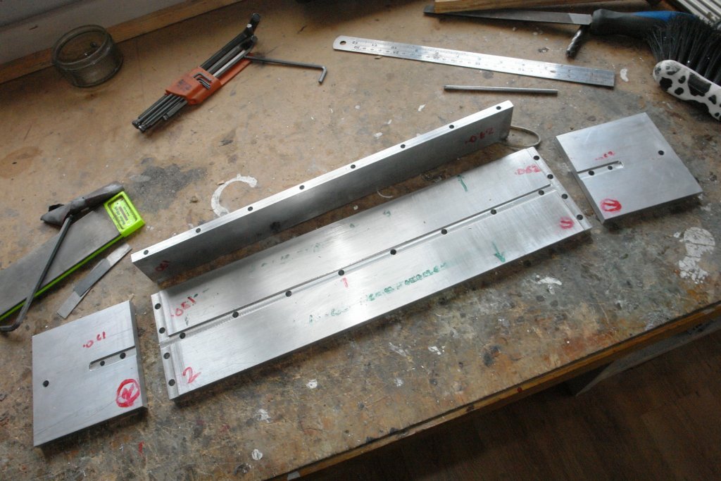
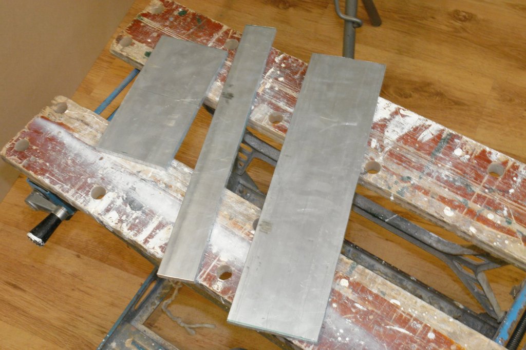
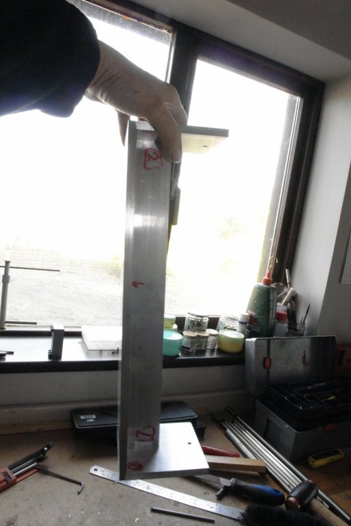
Thank you Derek, Allan, Richard and Bob. I'll keep the speed controller in mind for later in the build. I made a start on the column. Its not the most exciting component but its accuracy is critical to accuracy of the mill. Specifically the axis of the column must sit perfectly at right angles to the base (and hence the x,y table. I'll come back to this point in a future post. The first job was hacking out the 4 plates that will make up the column. Chopping through 3/8th inch plate with a hand hacksaw isn't that much fun (even in aluminium). I kept the two end plates together for initial machining hence 3 plates initially. I planned to do most of my machining off my existing milling machine bed - thus eliminating any inaccuracies introduced by holding the components in a vice. I have a side stop strip for the bed (made previously). It clamps accurately in one of the "T' slots and its side faces were machined when in the slot. Anything butted up against the stop is truly parallel to the table. All 3 plates for the top and back of the column were machined up against the stop with the front to back travel on the mill locked. This ensured all plates were exactly the same width. The ends of the plates were then faced off using the front to back travel, thus ensuring the squareness of the plates. The web was also machined parallel and square. The top plates were then separated and dowel holes and location slots machined in. The dowel holes are to facilitate later machining operations and the slots are to ensure accurate assembly. The two plates were machined in tandem on the milling table to ensure they were identical. The back plate was also slotted for location of the web and recesses were cut in the end to take the end plates. I was pleased with the accuracy of the assembly. In the following photo the plates are held together by friction while I am suspending the assembly by the top plate. I positioned the column next to the table to give an idea of the size of the mill. Next I need to drill and tap the plates so I can bolt them together.


-
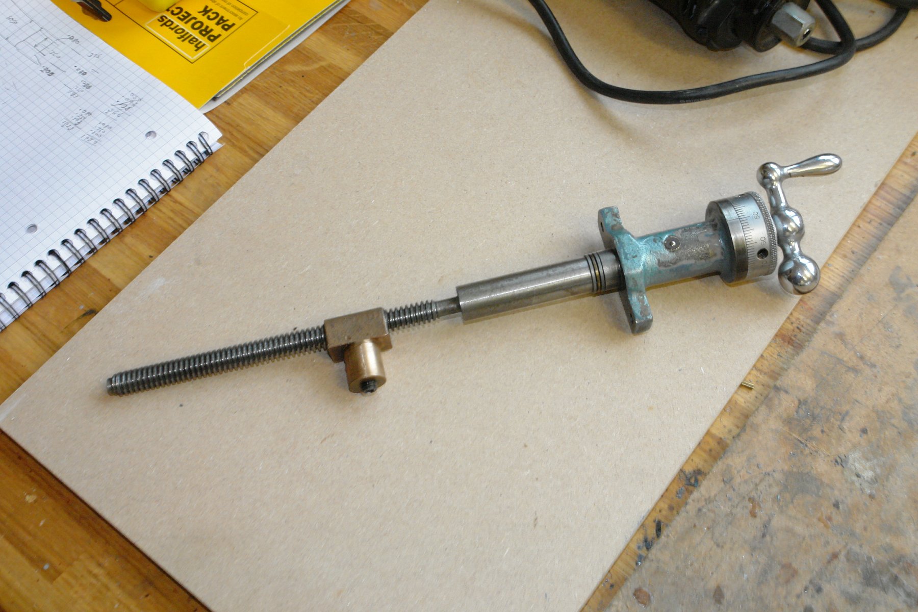
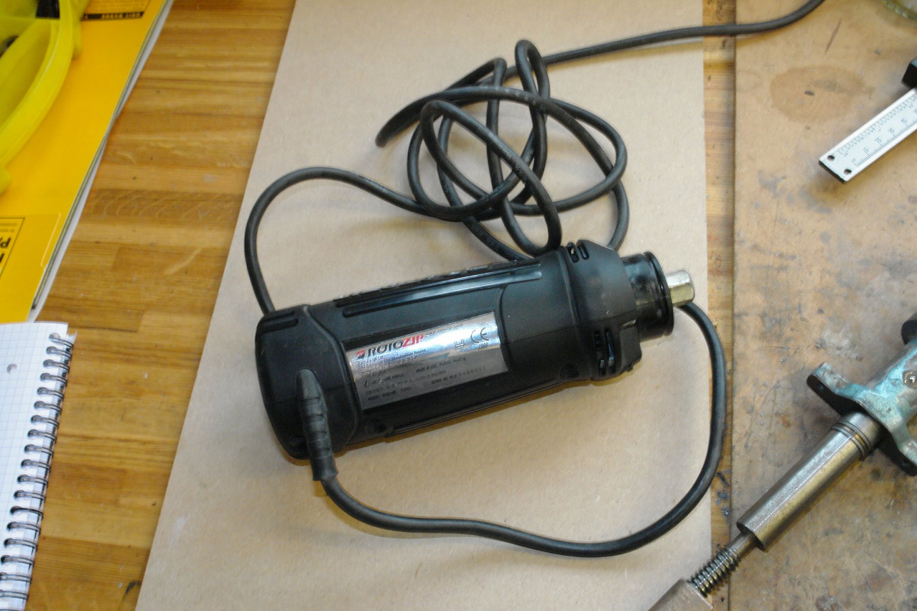
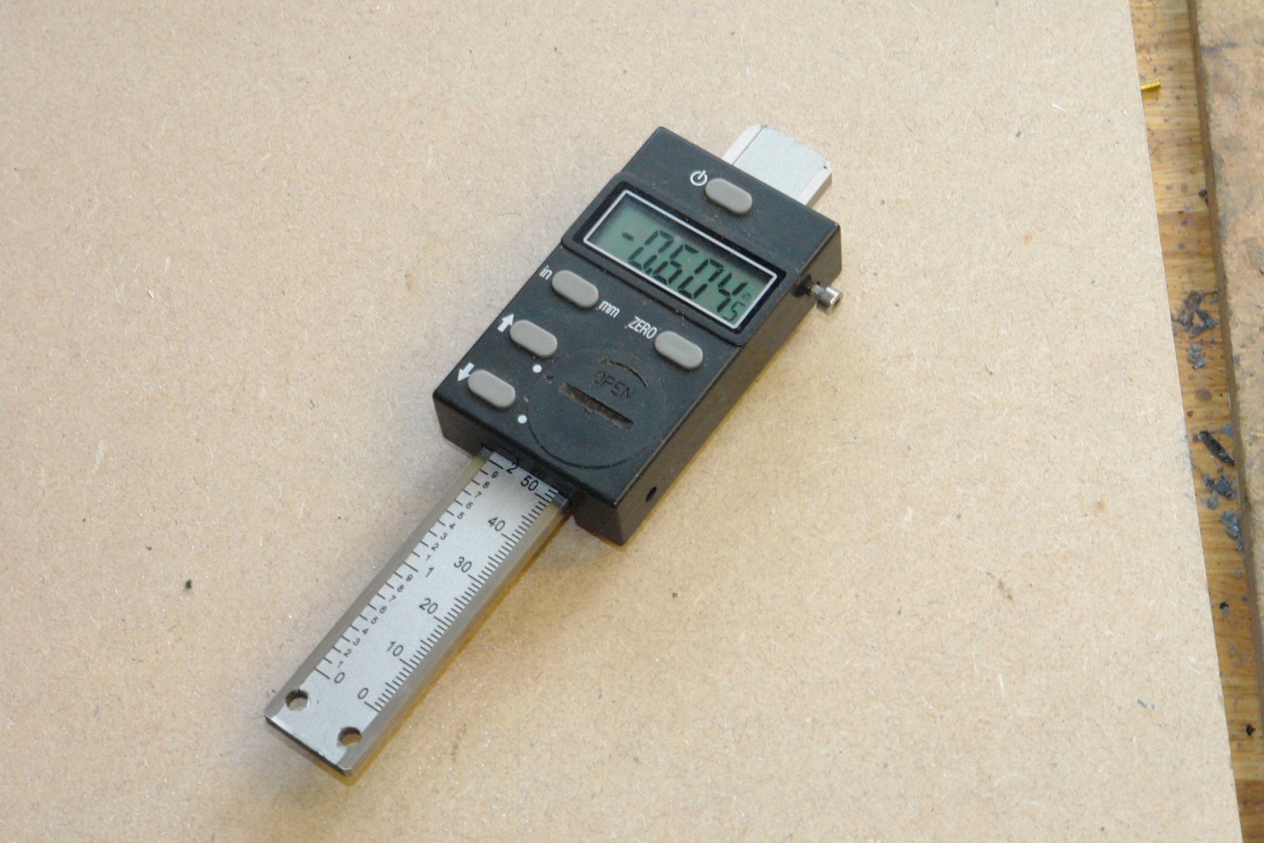
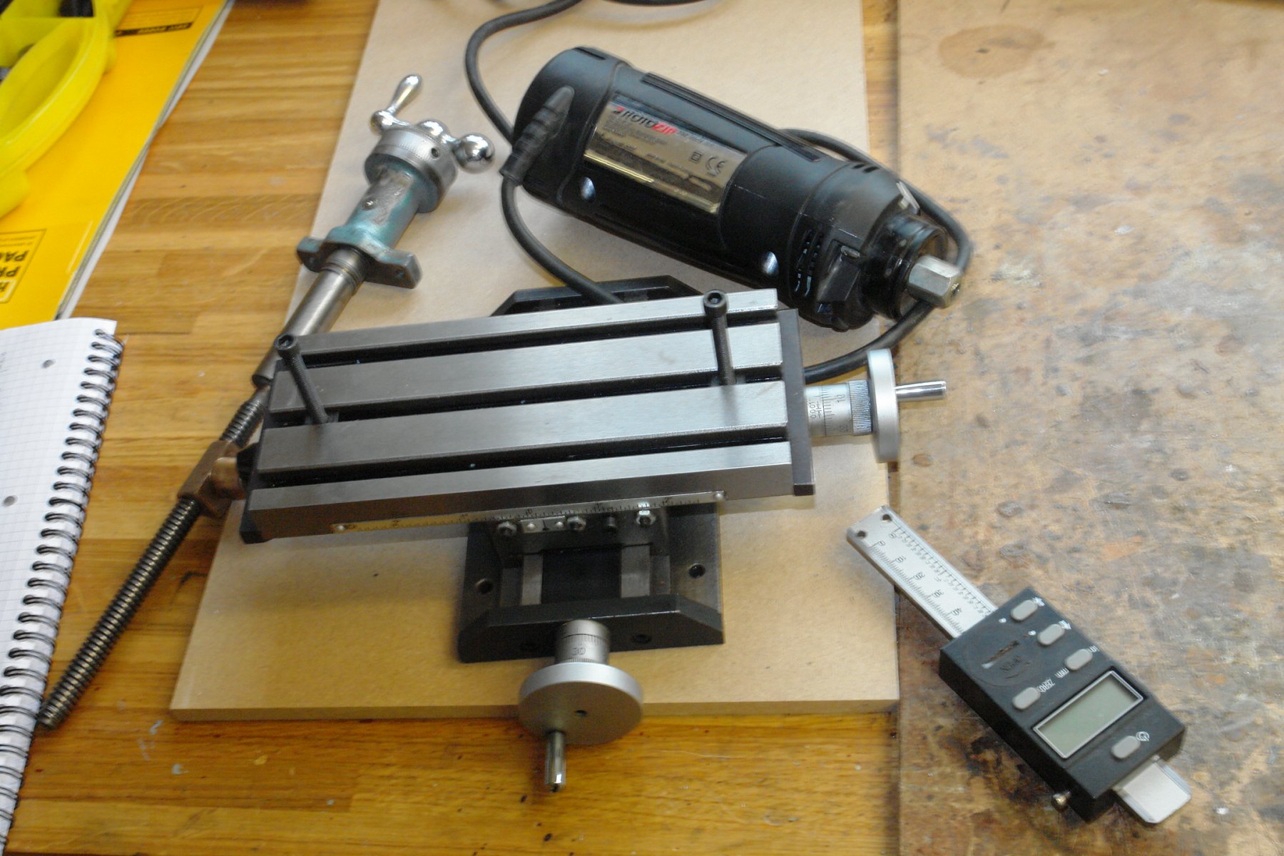
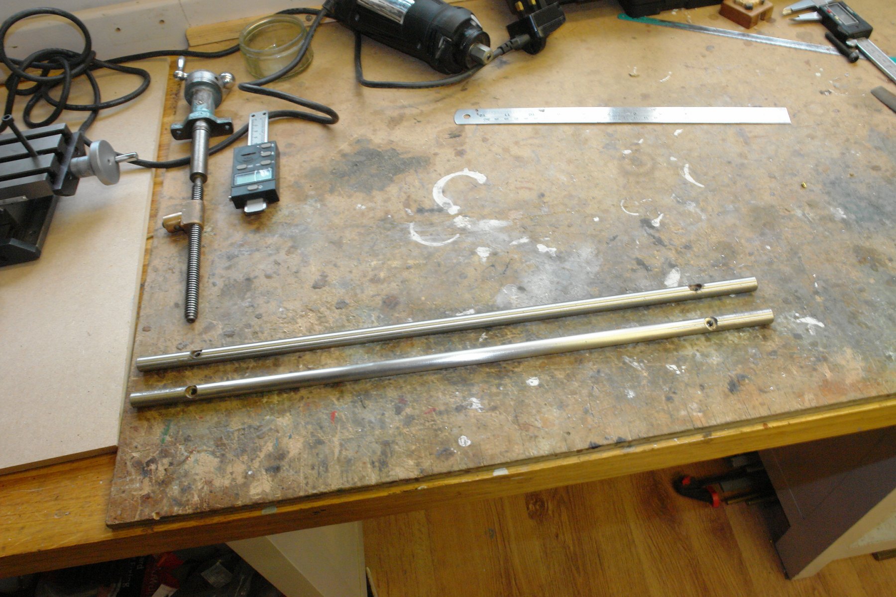
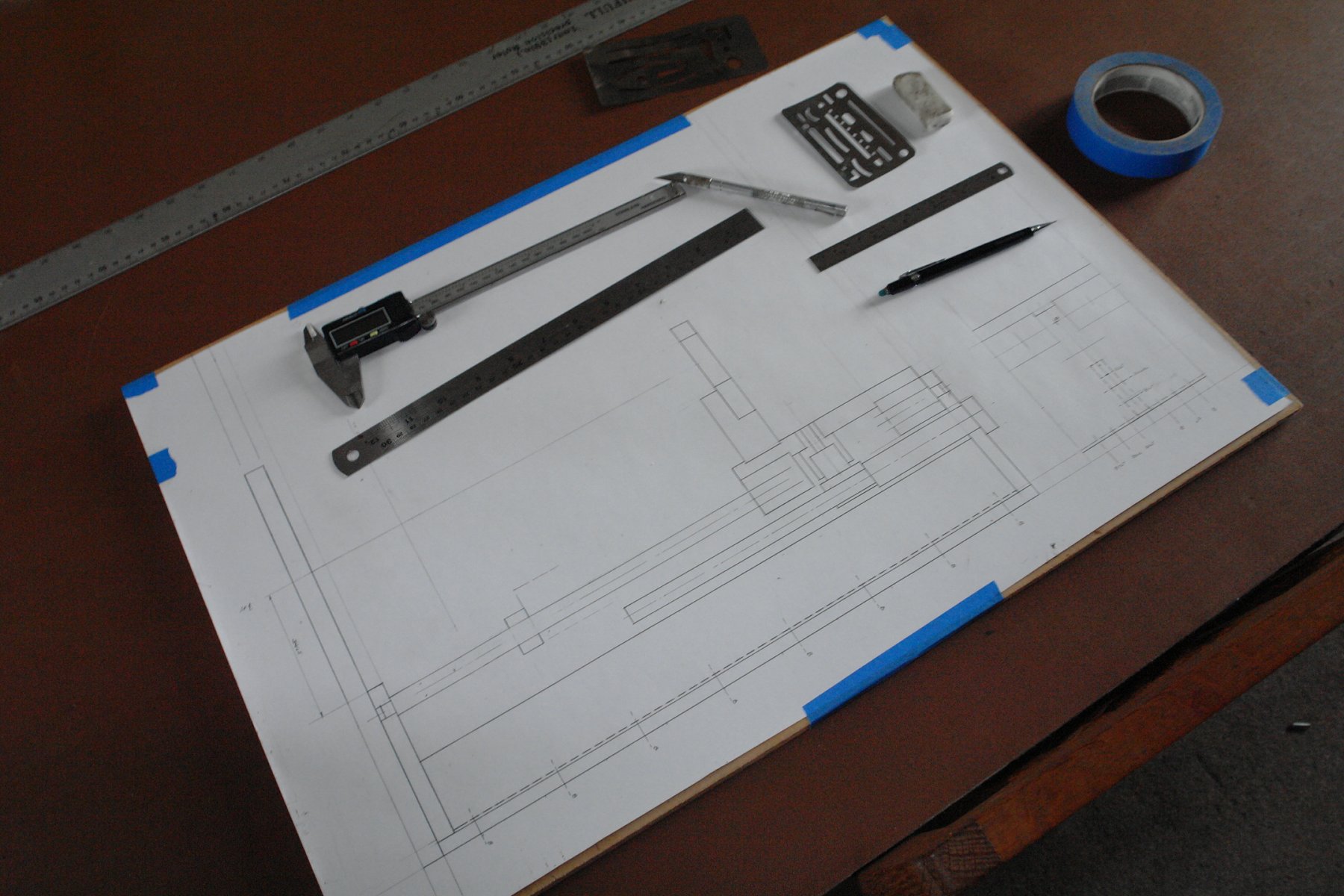
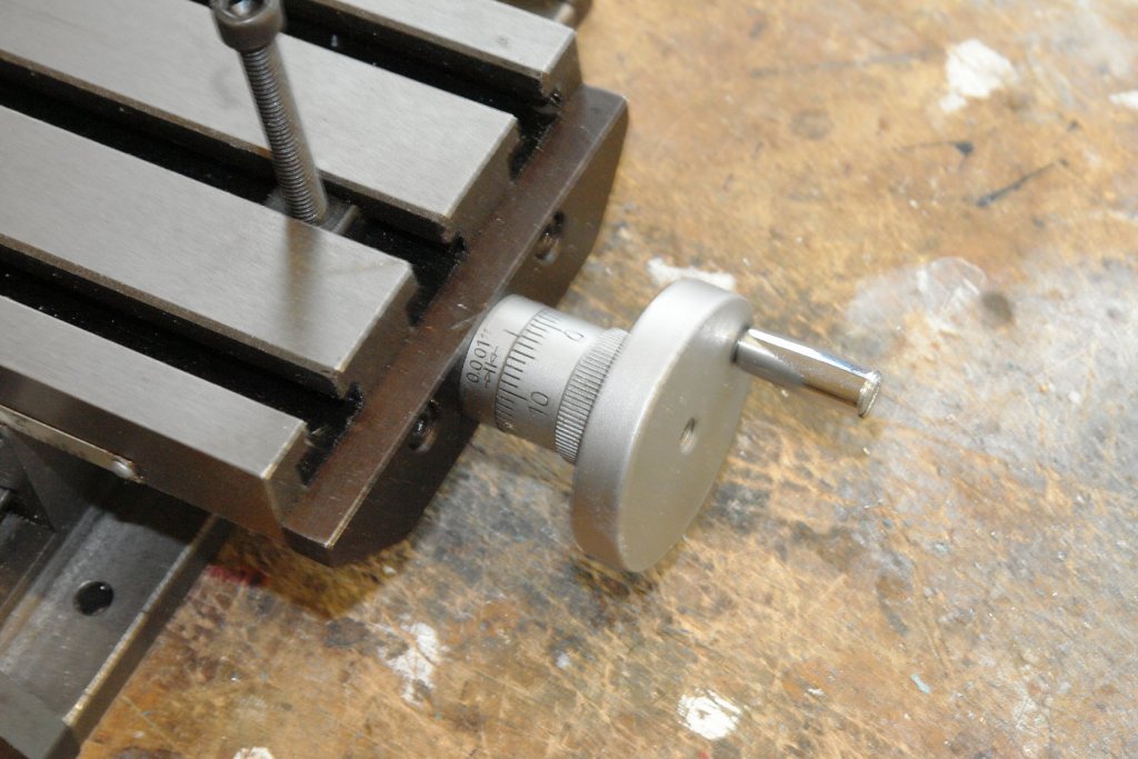
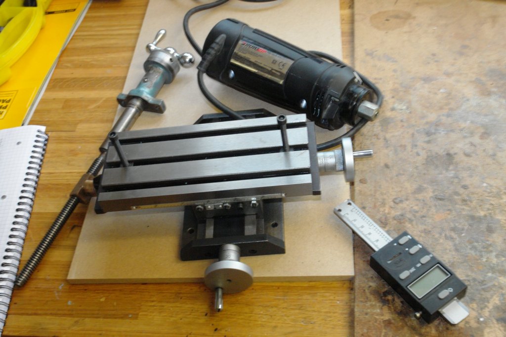
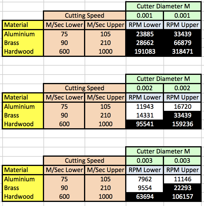
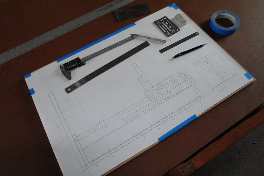
Two weeks ago I went to the local machinery suppliers open day and came away with a nice little X Y table. It came out of the redundant stock bucket and was a snip at £30. It is made of cast iron / steel (unlike many cheap fleabay products) and has gibs and locks on both axis. The hand wheels are calibrated in thousandths of an inch with one revolution giving .050 inch travel (20 TPI). The x travel is 5.250 inch and the y travel is 2.625 inch. I had been thinking about making a mini mill for a while. I find my bench mill is a bit too meaty for the smaller ship work and its maximum speed of 2400 rpm is much too slow for smaller drills and end mill cutters when working on aluminium, brass and hardwood. I did a bit of calculation on cutters of up to 3mm diameter (table below) and concluded that a spindle speed of 10,000 - 30,000 rpm wouldn't be too excessive. Having bought the table I had a hunt through my "rainy day" store and came up with the following:- Cross slide lead screw from my long retired Boxford lathe. This is nicely engineered with the screw mounted on double trust bearings and calibrated in tousandths (1 revolution = .100 inch). It will give me 6" Z axis travel. 2 speed "Rotozip" 550 Watt spiral saw body with speeds of 25000 and 33000 RPM. I have had this for 20 years during which time its had about one hours use. Its got loads of torque and nicely tight bearings. Ideally i would like to put speed control on it but as yet I'm not sure how. A digital read out, bought cheaply on a whim for £5. ( I will need 2 more). Its Ideally sized for the x axis. To make this a success I need to pay a lot of attention to the accuracy of the build but the first job was to come up with a design. I worked through a few options before coming up with the following general arrangement (drawn at full size). The column frame will be made out of .375" thick aluminium plate and the milling head will run on two pairs of linear roller bearings riding on on a pair of .473" bars that in a previous life were kitchen door handles. This should keep me off boat building for a while!


- 62 replies
-
- 18
-
-
Hello Spider. You are doing quite well really. Wife, kids and home extended one of my builds to 20 years. The kids now have homes of their own and are constantly compiling long lists of refurbishment demands. Crack on while you can, you never know what diversion is around the corner.
-
Thank you Michael and and thank you for all th likes.
-
Nice deck work Kevin. Its snowing in West Sussex as well - on Friday I was walking on the South Downs in warm sun and thinking spring had sprung.