KeithAug
-
Posts
3,986 -
Joined
-
Last visited
Content Type
Profiles
Forums
Gallery
Events
Everything posted by KeithAug
-

ancre La Salamandre by tadheus - 1:24
KeithAug replied to tadheus's topic in - Build logs for subjects built 1751 - 1800
Nicely finished Pawel. Remind me - what wood are you using? -
Dan, I am still wondering how you are able to do this. Do you have an army of nanobots secretly working away? Very informative explanation, thank you.
- 287 replies
-
- 3
-

-
- michelangelo
- ocean liner
- (and 1 more)
-
Hi Nils I assume the two guns mounted to fire forward over the deck are to keep the crew on their toes?????
- 692 replies
-
- 5
-
-
- eagle of algier
- chebec
- (and 2 more)
-
Hi Per I find rails quite tricky. Your approach seems to work well so I may give it a go next time.
-
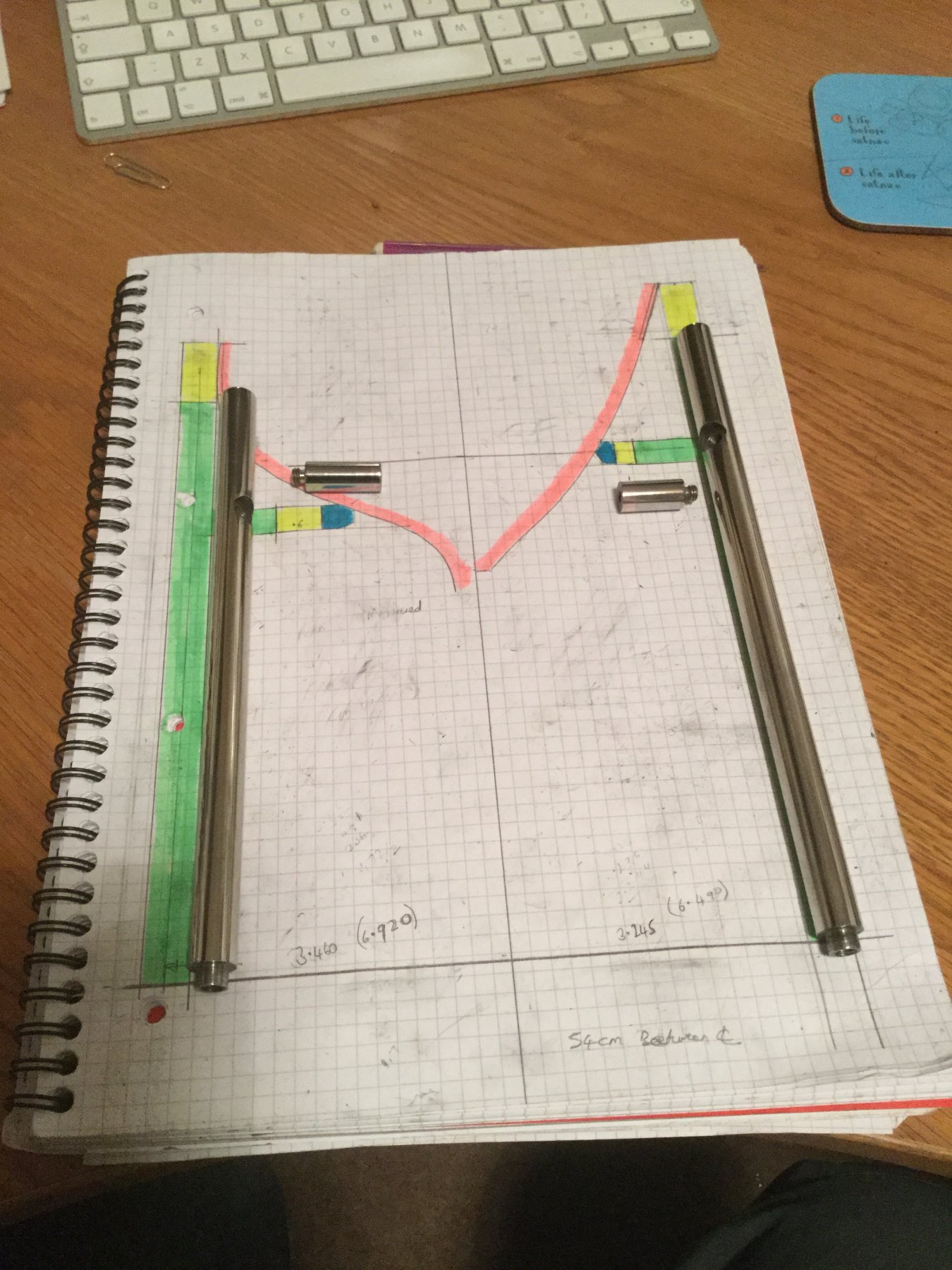
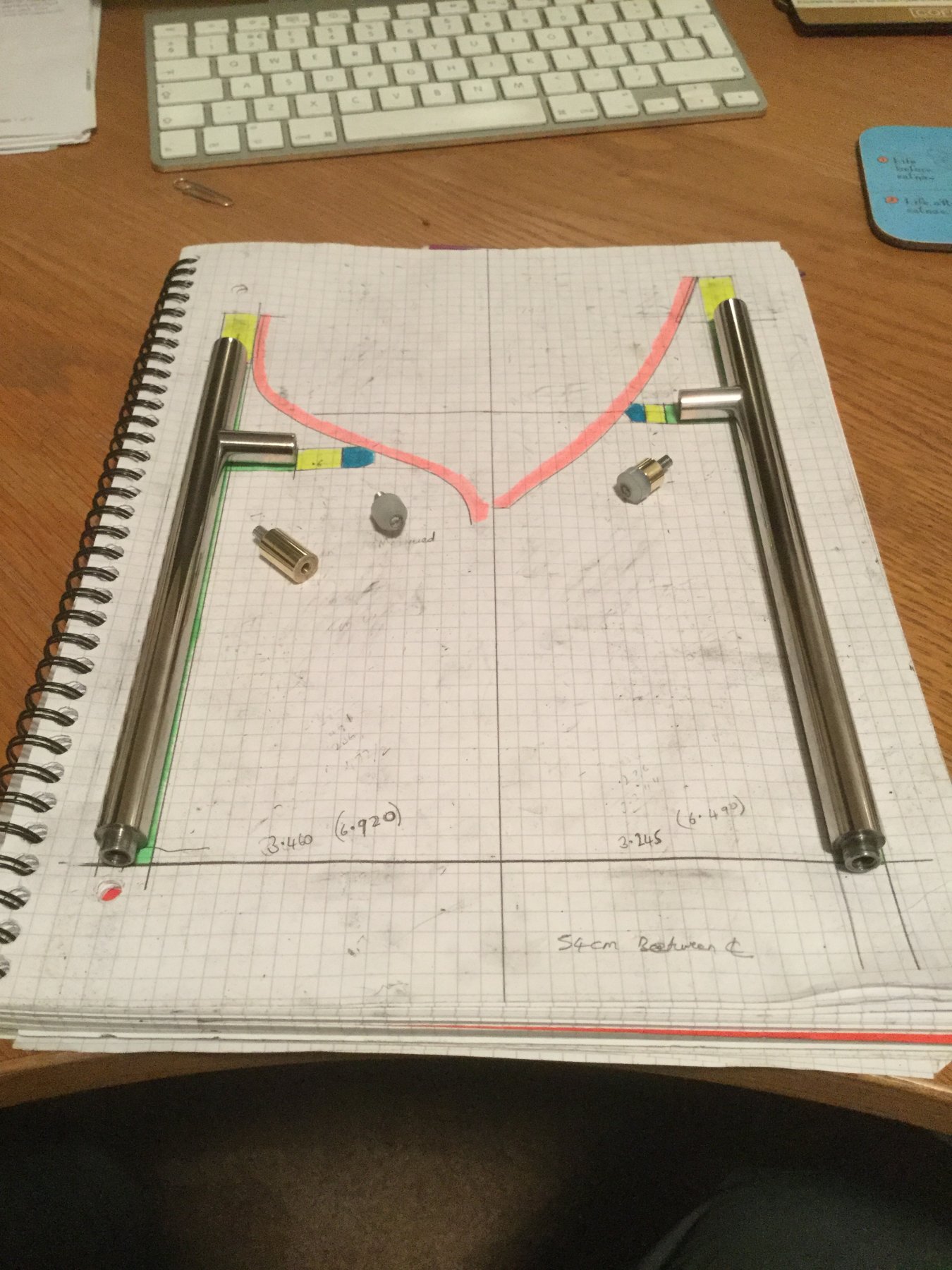
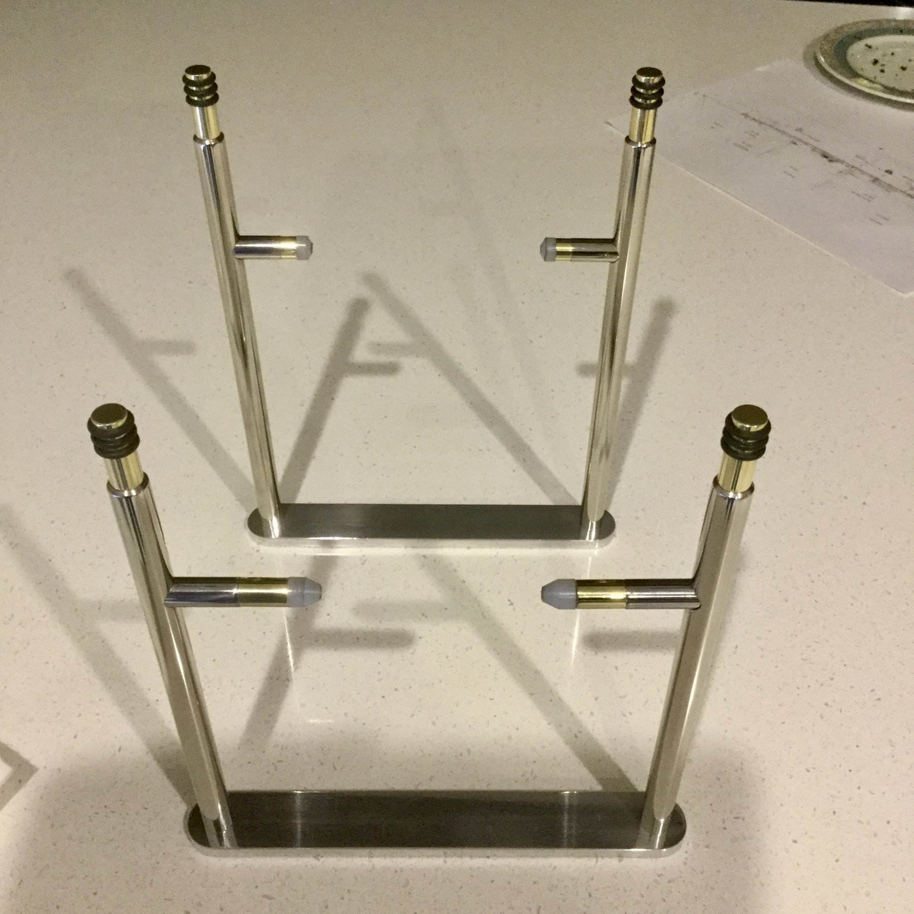
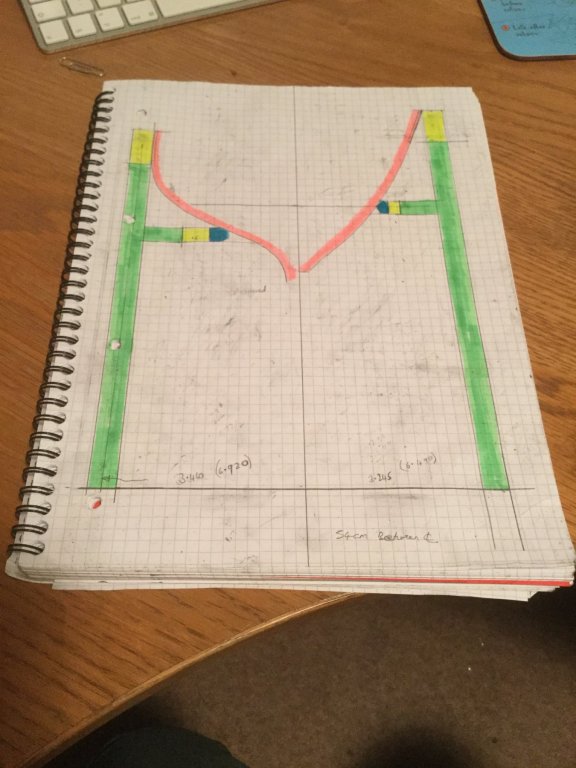
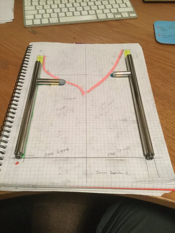
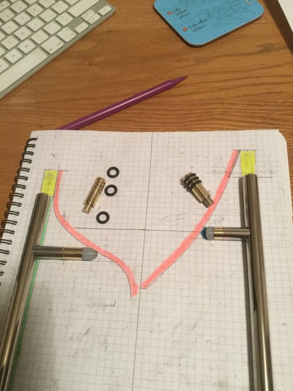
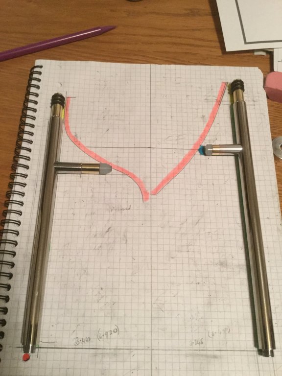
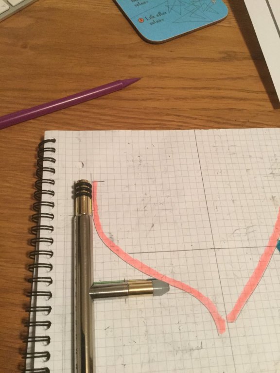
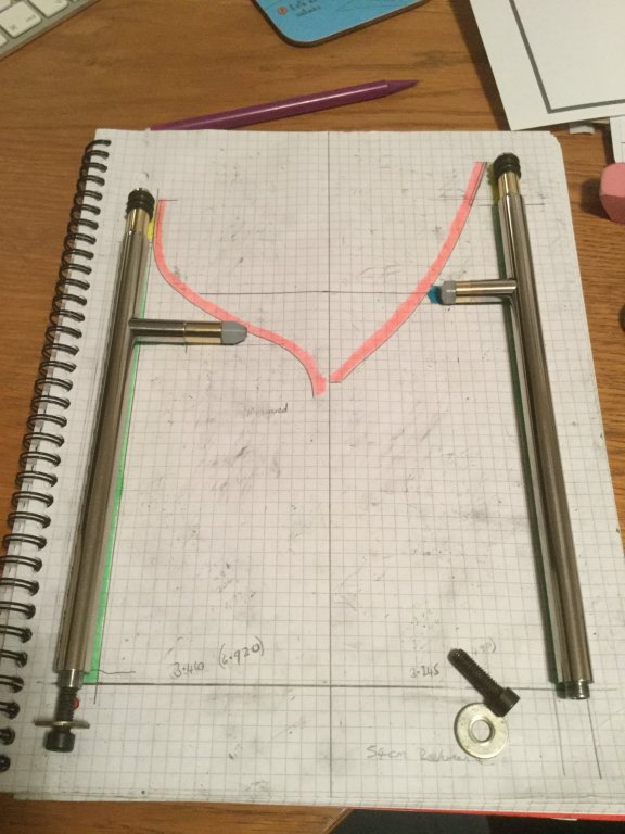
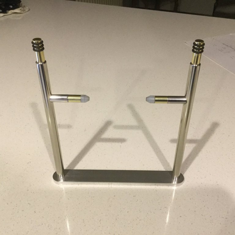
Over the last couple of days I made progress on the stand. Im planning to suspend the yacht on 4 legs and the starting point is to work out the proportions of the legs. This I have done by selecting the frames where the legs will sit and then drawing the adjacent leg to scale. The legs are made from polished stainless steel. Not a material I am very fond of working with. Where the side arms abut the hull I wanted something more forgiving than metal so the ends are machined from nylon. A brass insert between the side arm and nylon end will can be machined to tune final fitting. The top of the legs provide side restraint and where they bear on the hull they softened with "O" rings. The "O" ring grouves could have been machined directly into the stainless but I thought the brass end added a bit of interest. The bottom of the legs are drilled and threaded to take the base attachment bolts. A 1/4 inch thick stap joins each pair of legs. The base board is next.


- 882 replies
-
- 12
-
-
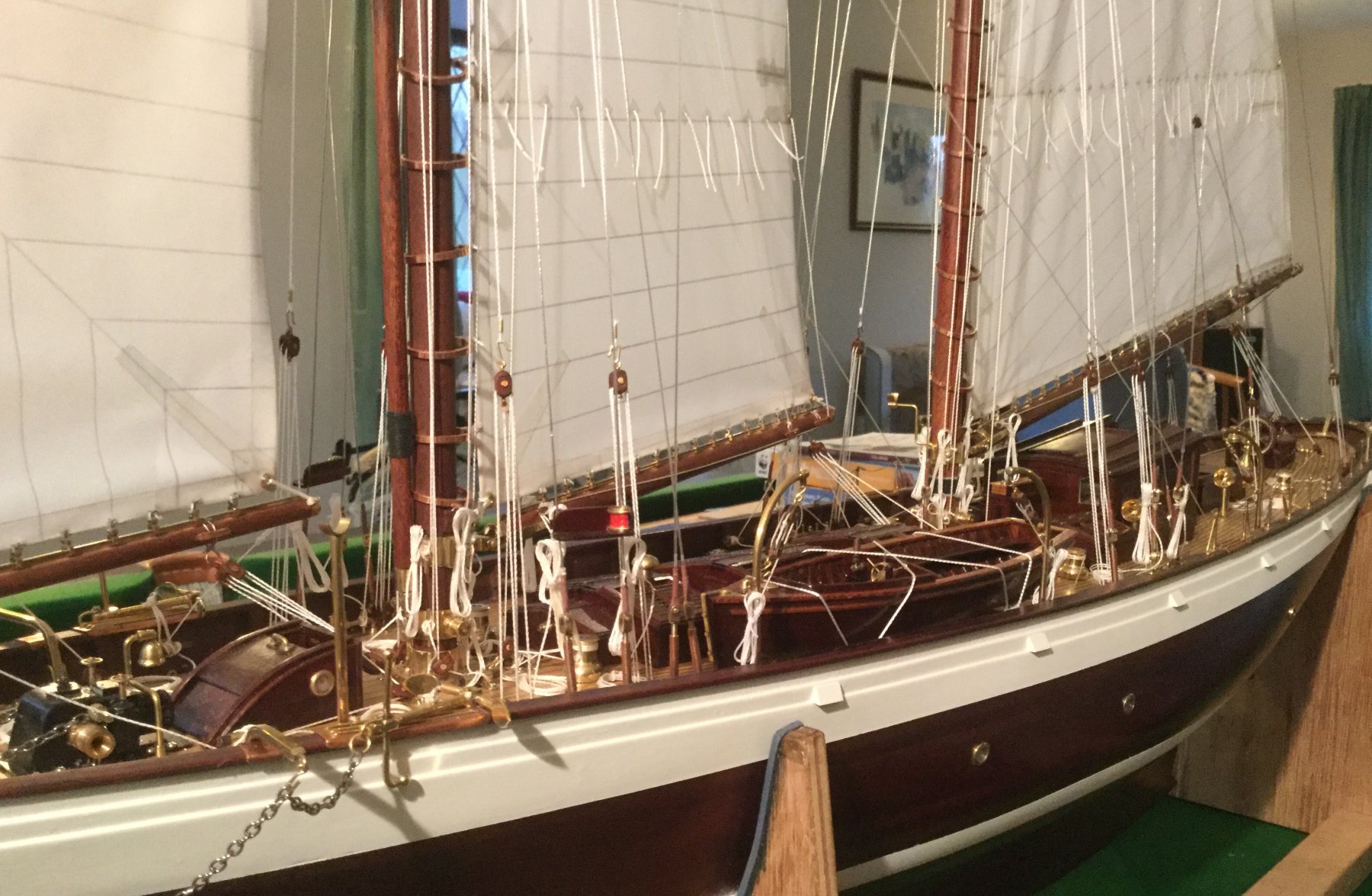
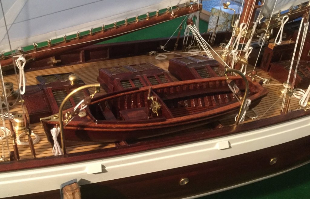
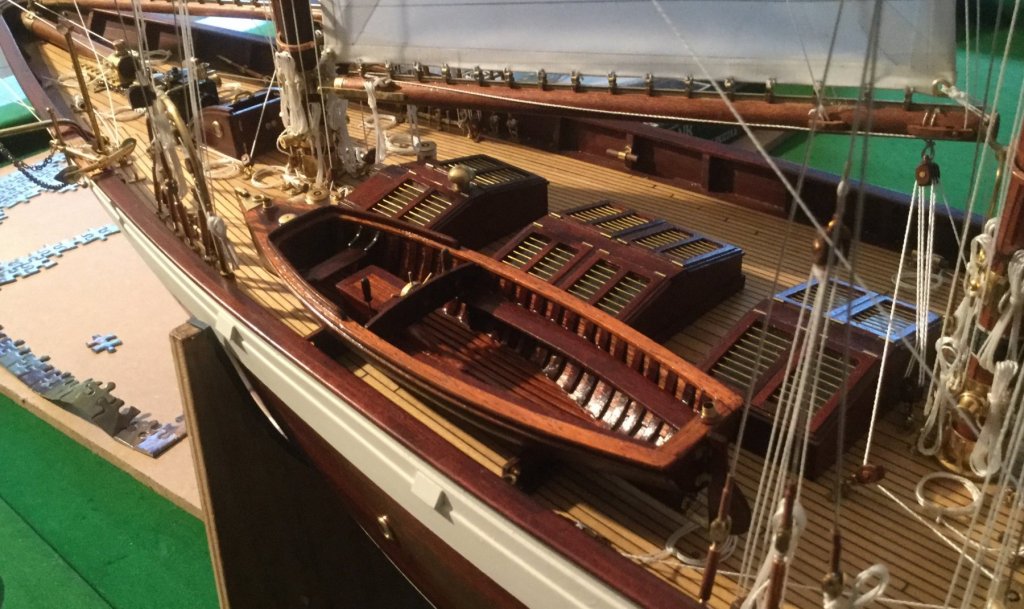
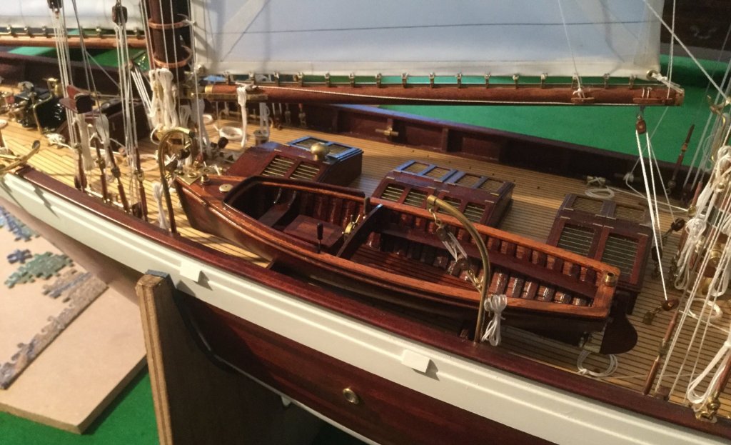
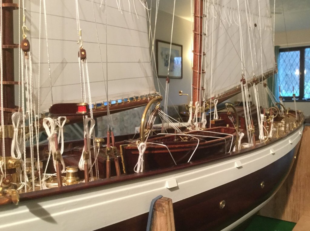
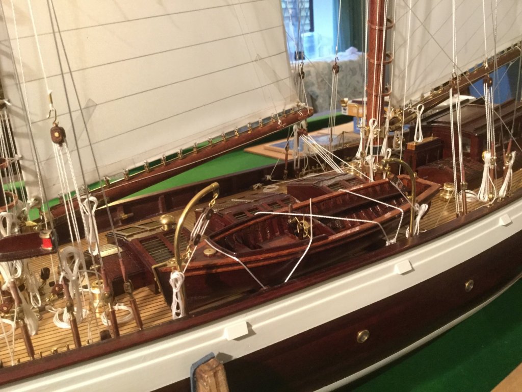
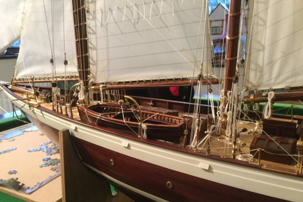
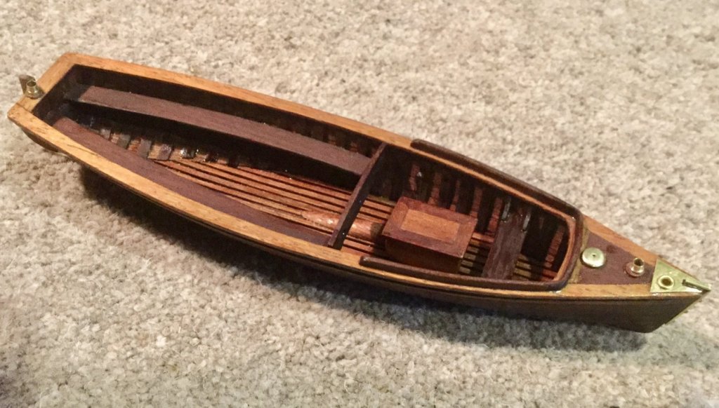
Pat, thank you and yes she is a rich mans toy. Hakan, Thank you. John, Thanks. a wee dram sounds like a good idea. The time came to introduce the launch to it mother. I made it cradle from mahogany strip, shaped using the templates for the frames. The holes for the lashings were reinforced with brass rivets (visible in the photos). The cradles are each held down using 4 spectacle repair screws. I made a card template to align the cradles and get them in the correct position. When the launch is on the cradles it fills the available space and must restrict deck operations to a significant degree. Altair actually has 2 other boats, both smaller than the launch. Photographs of Altair frequently show no boats on deck and when they are carried the smaller boats seem to be favoured. In the photograph immediately above I have removed the aft davit to ease access. I lashed the launch in place using a length of twine. Several photographs show the launch lashed in place. Mother is very pleased to have baby on board. I'm going to try and make some progress on the stand this week - before a diversion into refurbishing my daughters bathroom - yuk!!!


- 882 replies
-
- 17
-
-
Nils, Nice Pinnacle - although I did wonder how you had managed to build it in a couple of days between posts. Your explanation put my mind at rest as i was beginning to think you had discovered time travel.
- 692 replies
-
- 6
-
-
- eagle of algier
- chebec
- (and 2 more)
-
Thank you Tim. The darker mahogany is circa 100 years old. It is quite dense and close grained. It came from a once very nice dining table which i suspect was made from prime timber. Not very much like the mahogany sold today. The lighter mahogany was from block flooring recovered from a old building before being relaid on my daughters kitchen floor. I'm using up the offcuts. I think its about 50 years old. It does have a more open grain and fibres lift when coarse sanding.
-
Thank you Pat. John, Sorry, I would have but I could not find spark plugs small enough ( i think in 1931 it was a petrol engine). John, You sound like my wife, have you been taking lessons? Richard - thank you.
-
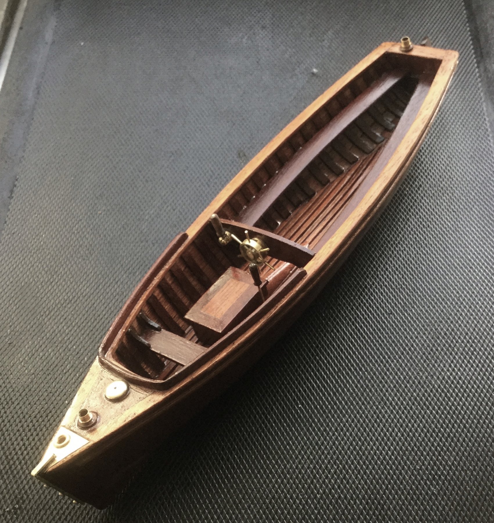
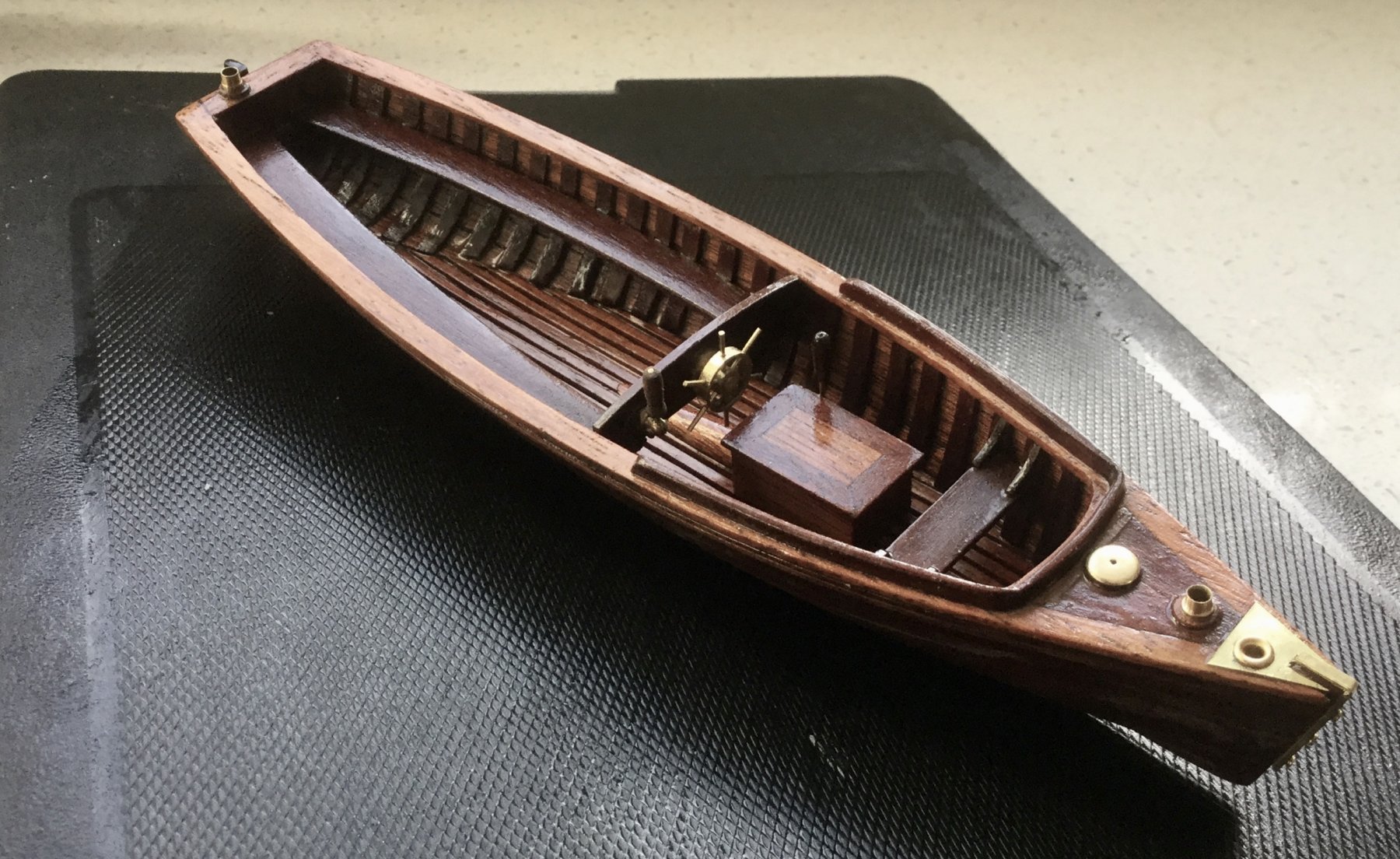
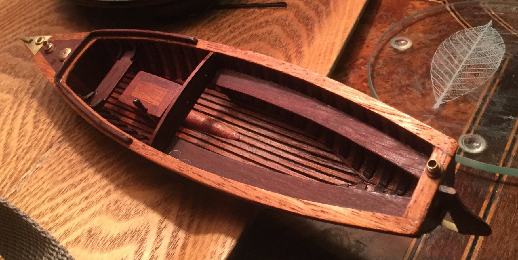
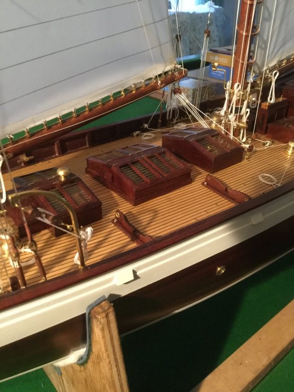
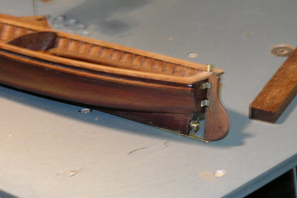
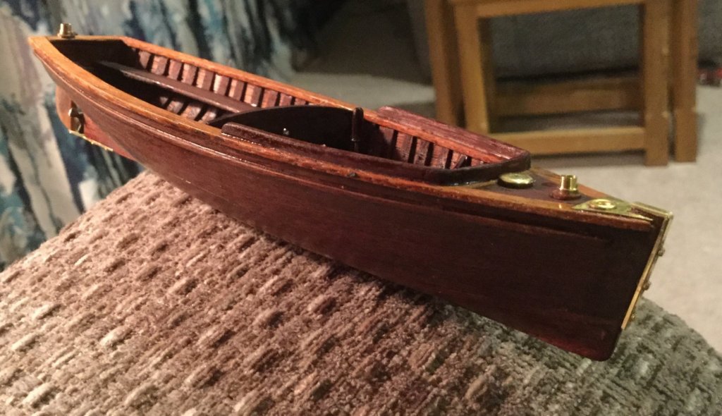
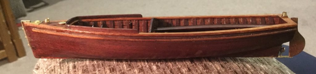
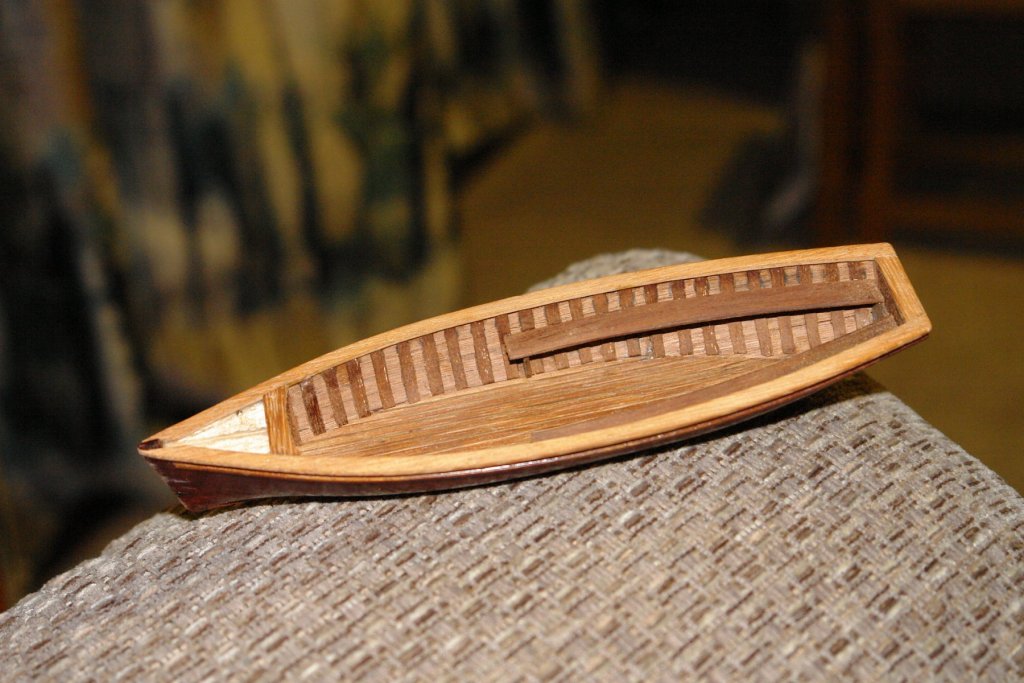
Over the weekend I almost completed the launch. The foredeck was planked - hard to tell though. I also made the foremost bench together with the 4 gussets that reinforce the attachment to the hull. The trickiest bit was the splash rail. The corners were much too tight to bend so these were cut from solid. Once mounted on the deck rail the were joined buy 3 bent planks. . It's probably worth explaining that I am using 2 sources of mahogany (one much lighter in colour) to add interest to the launch. I then added the interior detail of the engine housing, prop shaft cover and instrument bulkhead. The engine housing has the gear lever mounted. The rudder then went on with the bracket to support the lower end. I made and mounted the brass fittings on the small foredeck. The brass protective strip for the stem was also made and mounted. By this stage I had given the inside a coat of poly - still a bit wet when the following photos were taken. I have delayed mounting the wheel and throttle lever until the internal painting is complete. I now need to make the cradles for mounting the launch on the deck.

- 882 replies
-
- 15
-
-
Hello John. I always wanted to retire to Harrogate. A Yorkshireman down south is like a duck out of water. Welcome and I look forward to seeing your build.
-
Amazing Dan, but it strains my eyes and hurts my head. May need to get my eyes sorted.
- 287 replies
-
- 1
-
-
- michelangelo
- ocean liner
- (and 1 more)
-
She is looking very good Nils. The final few photo's show her off a treat.
- 692 replies
-
- 3
-
-
- eagle of algier
- chebec
- (and 2 more)
-
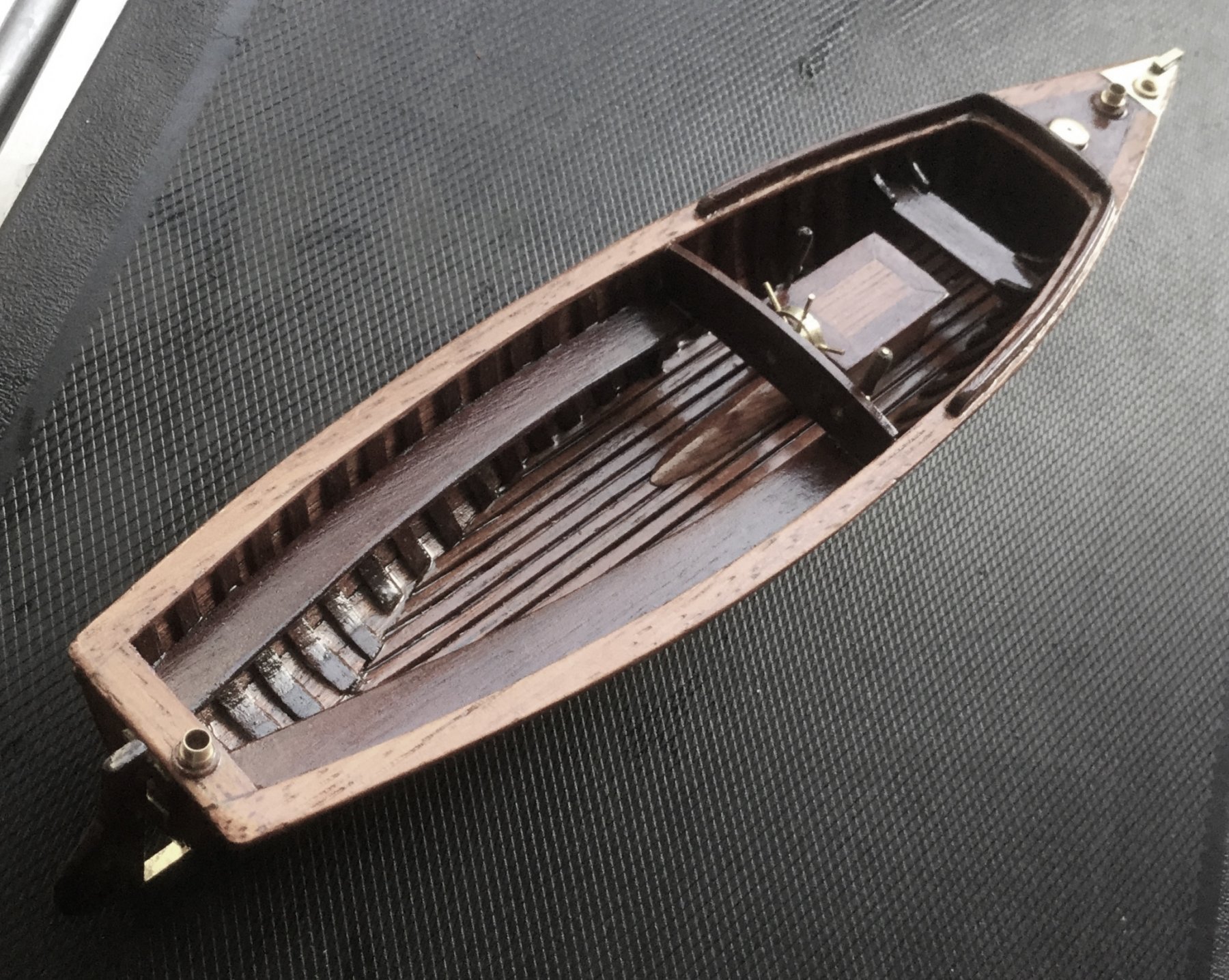
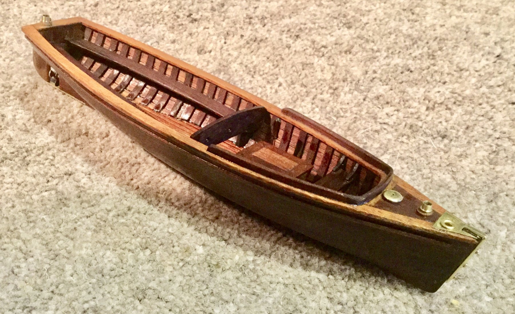
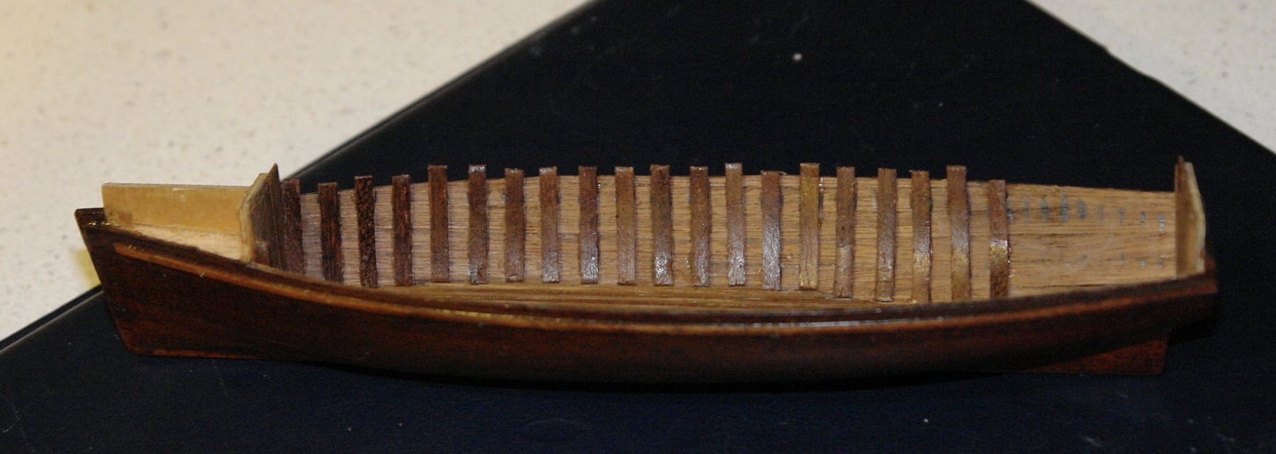
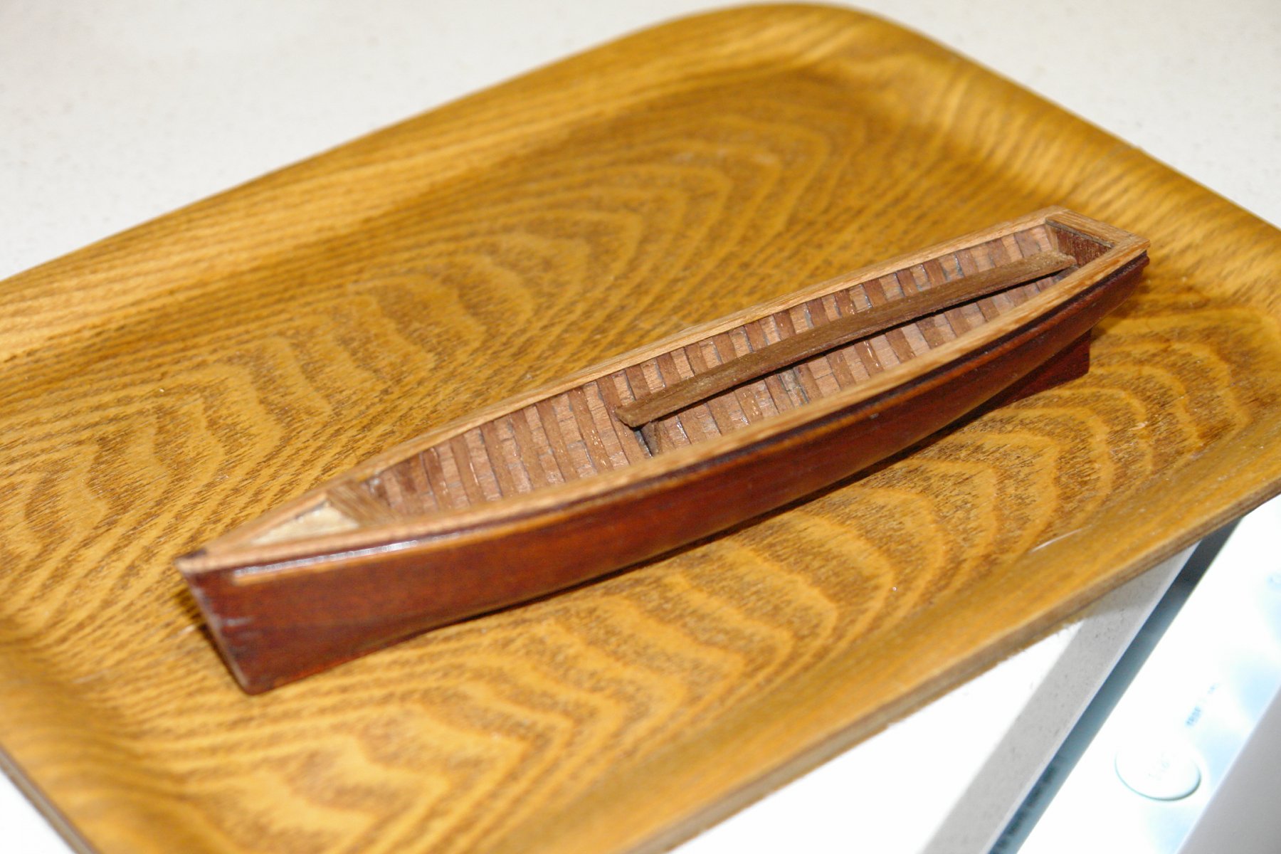
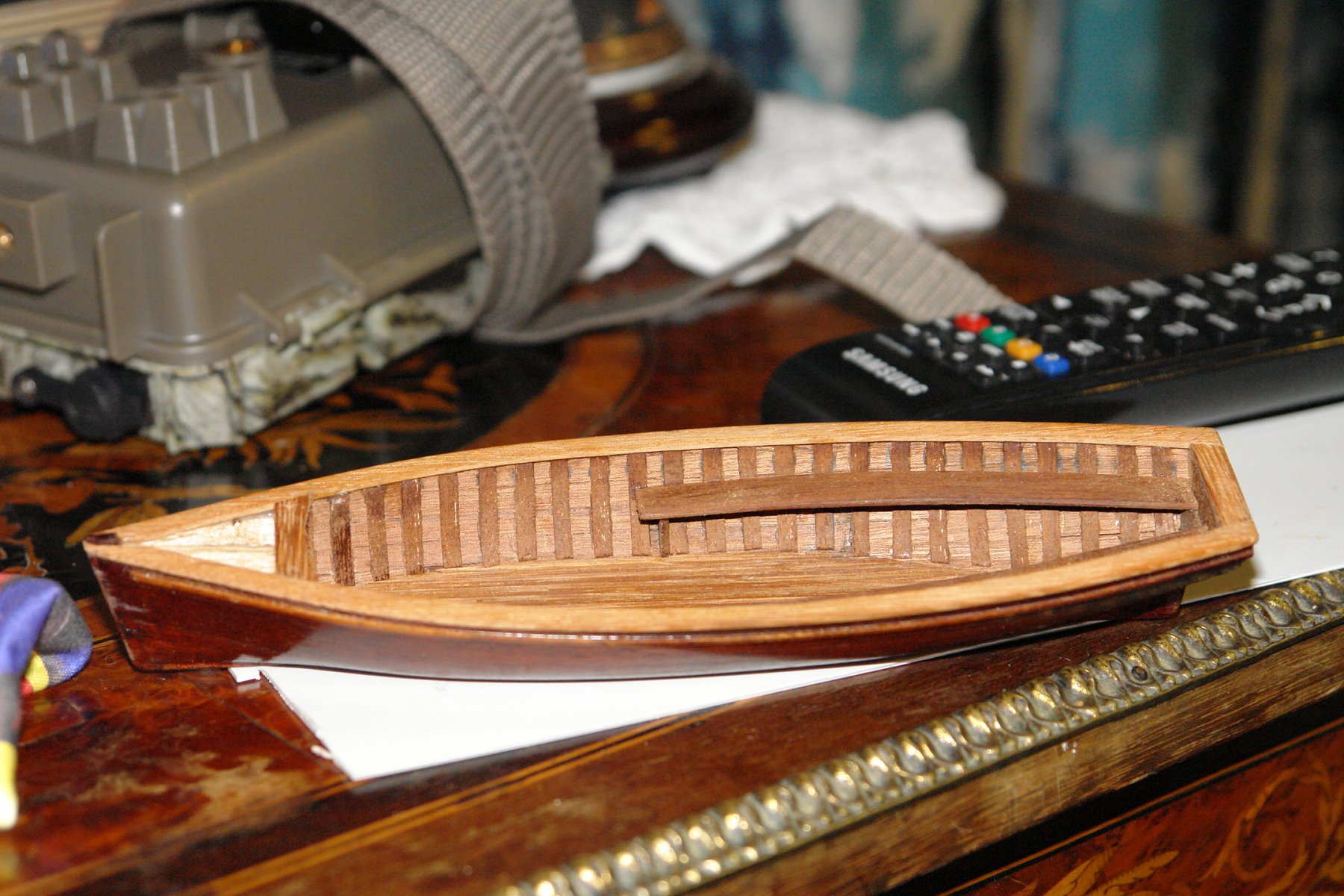
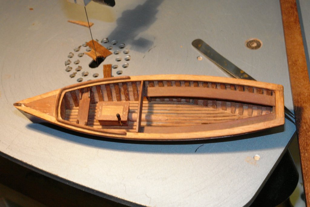
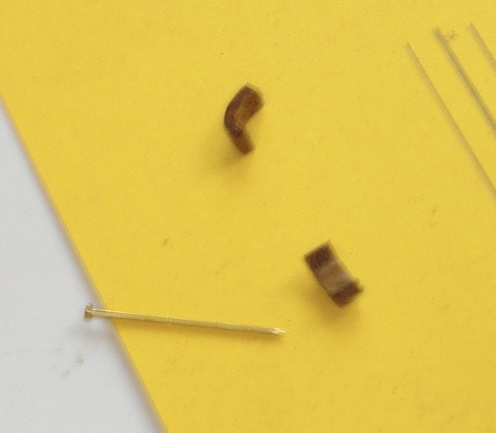
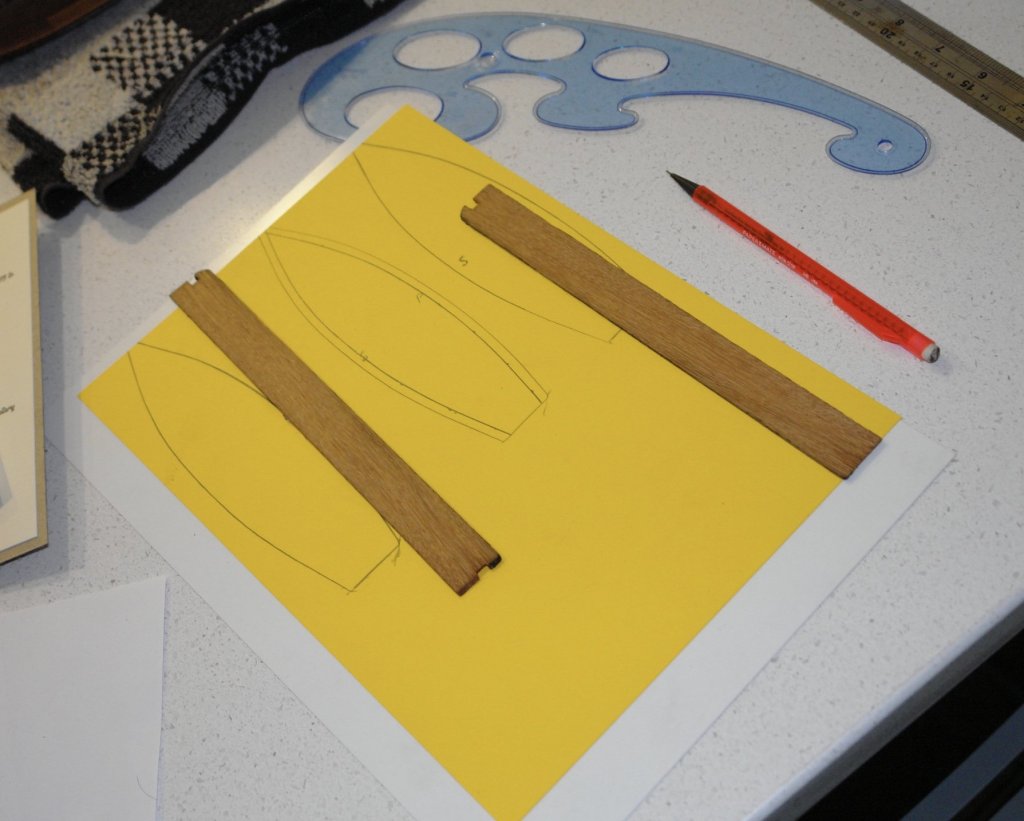
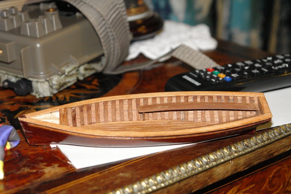
Christmas and New Year over and I am delighted to announce that the management has graciously agreed to the reopening of the shipyard. Pat / Bedford - Thank you for your contributions. Mark - Your light sabre is obviously very clever, my skill with manufacturing automation relegates me to the 3rd division, more of a latter day Zorro than Luke Skywalker. Paul - Thank you for taking the trouble to browse my log. I continued this week with the building of the launch. I completed the planking of the the inside of the hull and then marked out the position of the ribs before attaching them. I needed some quite tight bends but I managed them without too much trouble / breakage. Two bench seats run along the sides from amidships to the stern. I shaped these using the previously drawn hull lines. They are currently glued in place but I think I will add more supports for aesthetic / realism reasons. I spent last night awake making and fixing the capping rails in my head. Not very productive I would have been better occupied getting up and doing the job. Anyway the plan involved cutting the rails to shape using the inverted hull as a template. By about 3am I had rejected the alternative plan of bending straight planks to fit. My plan for clamping the rail while the PVA dried was effective if not a little basic. It involved holding it in place with finger pressure while blasting it with the hairdryer. My fingers got a little warm in the process but I gritted my teeth an toughed it out like a man. The next job is to plank the small section of foredeck before getting on with the internal fit out.


-
Hello Pat. Thank you for taking time to look through the entire log and for your kind comments. I am thinking of putting a miniature letter/envelope in the drawer explaining who I am ----- a time capsule for future generations of shipwrights. If my explanation has failed at any point please let me know and I will fill in the detail.
-
ancre La Salamandre by tadheus - 1:24
KeithAug replied to tadheus's topic in - Build logs for subjects built 1751 - 1800
Very nice hatch Pawel. -
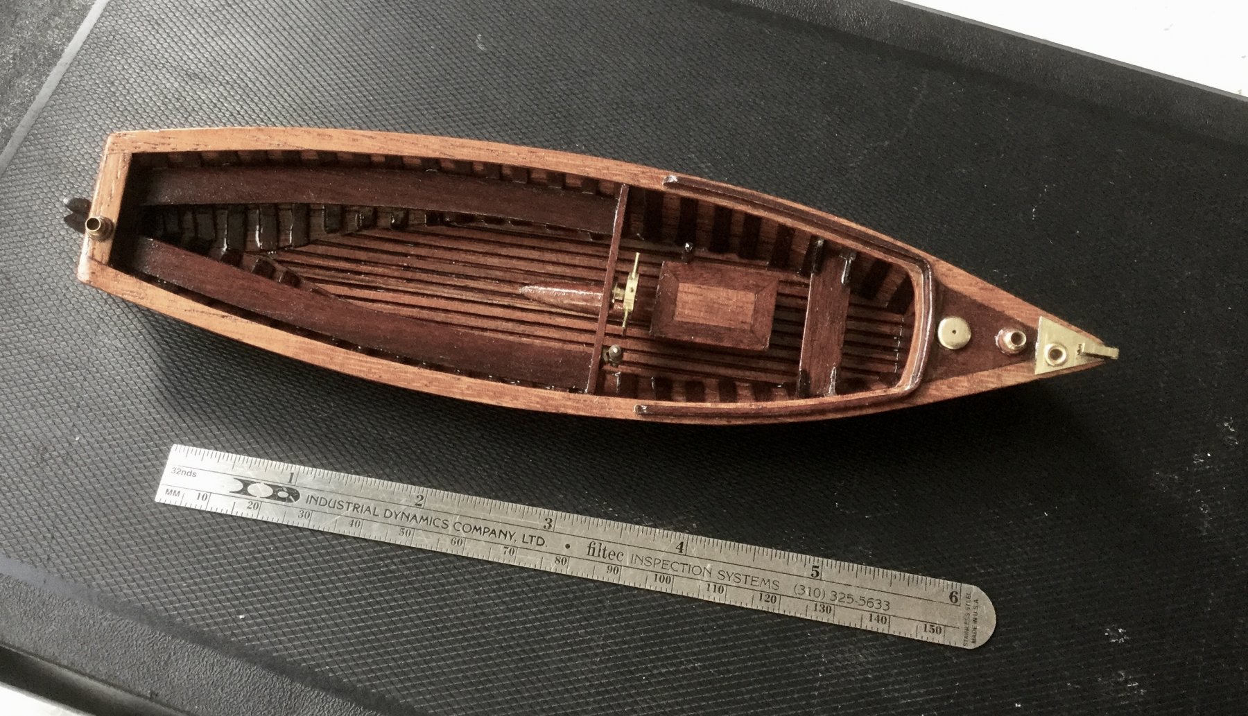
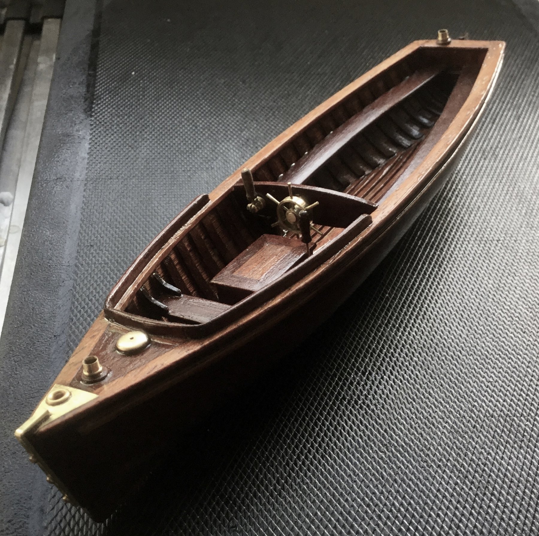
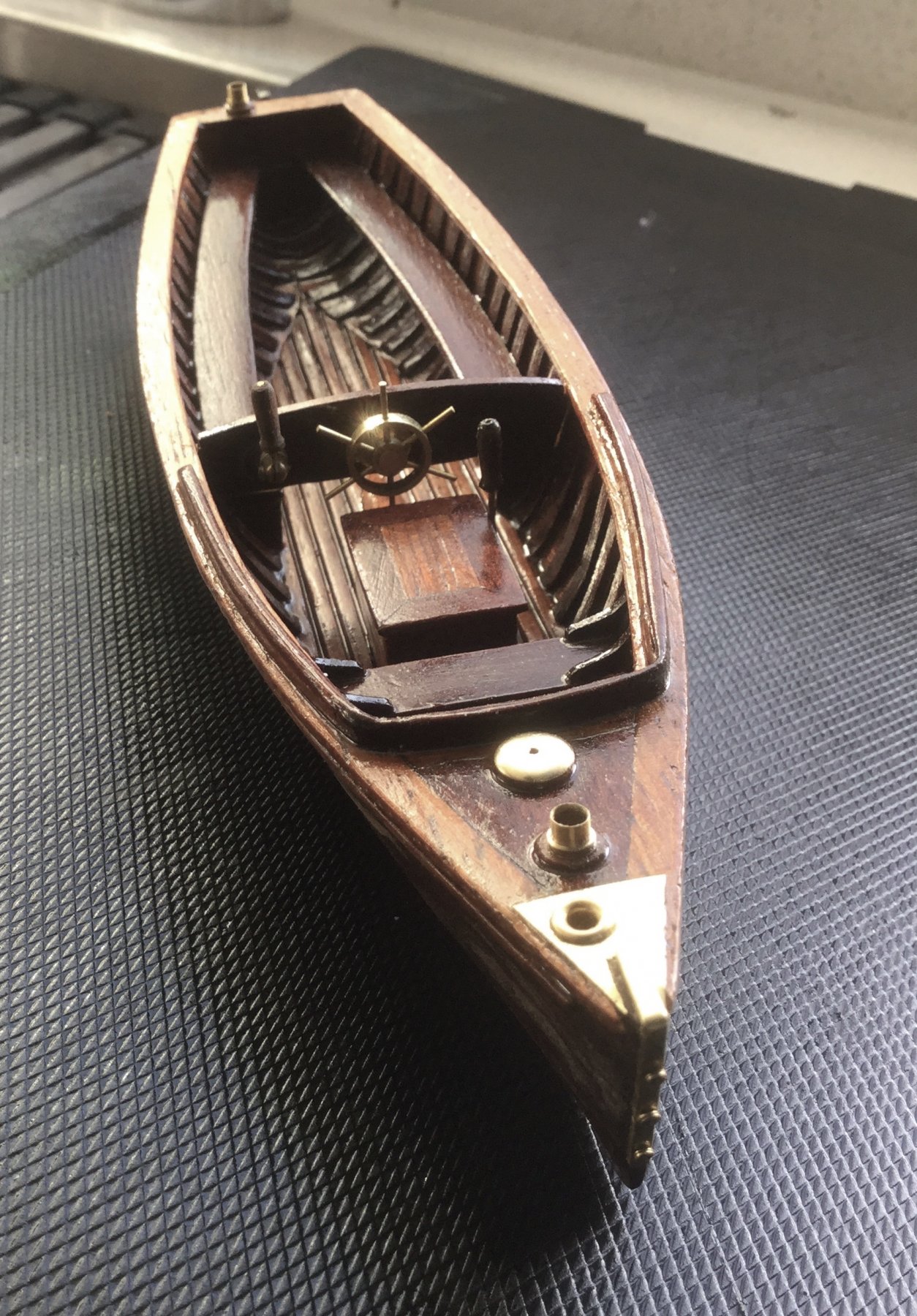
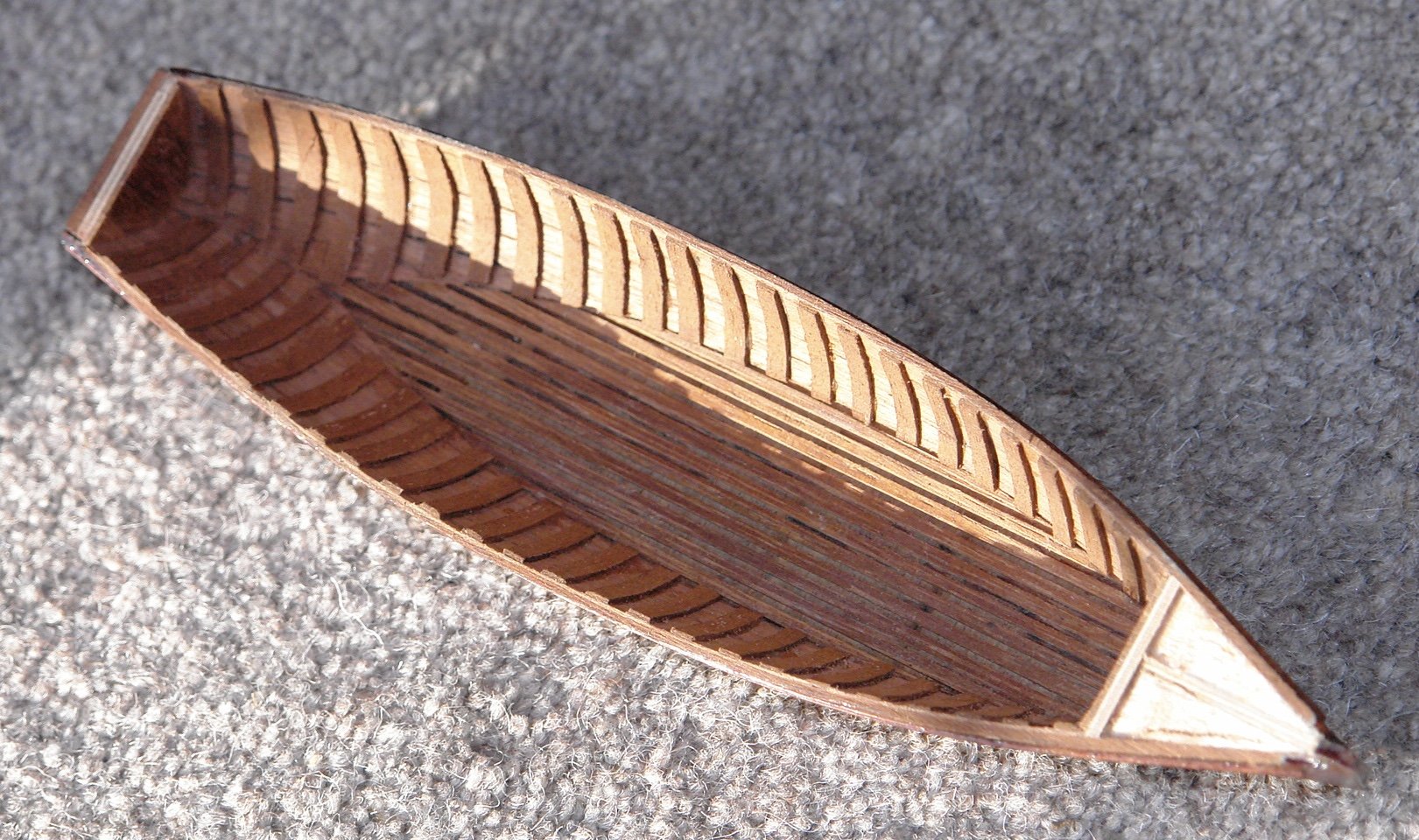
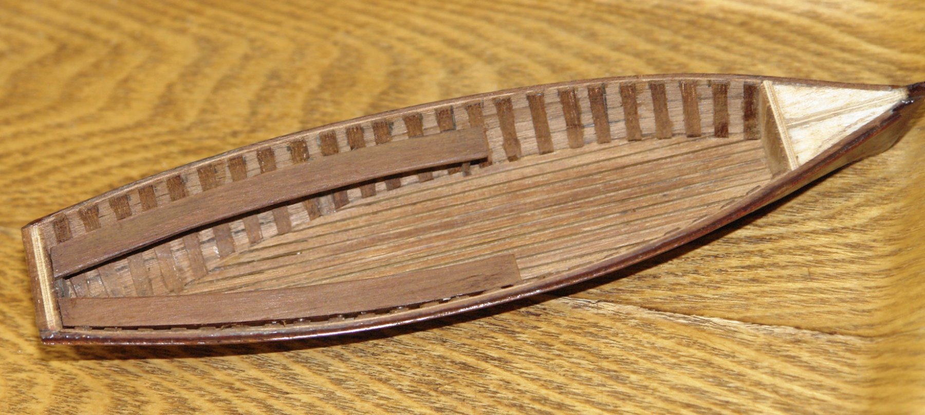
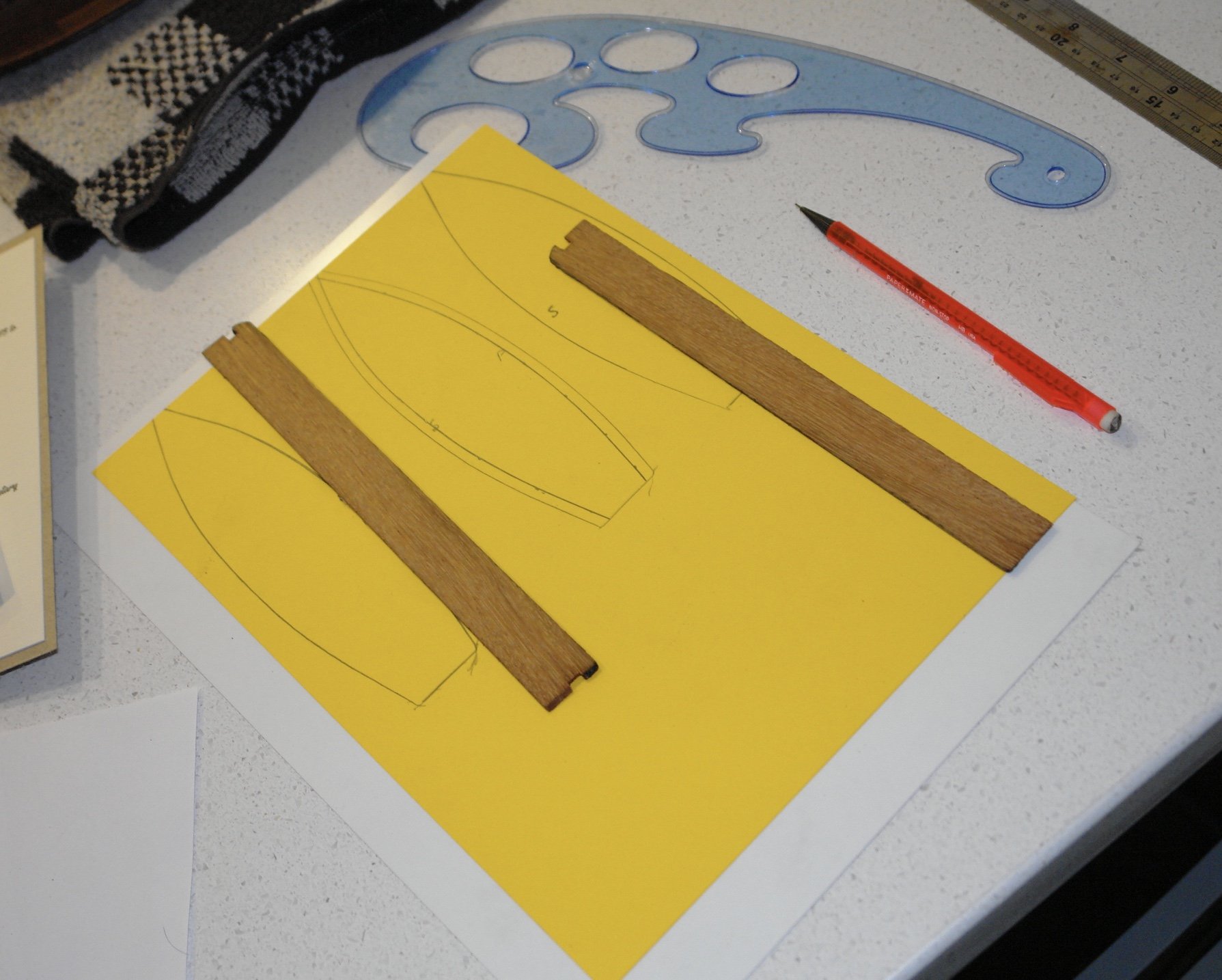
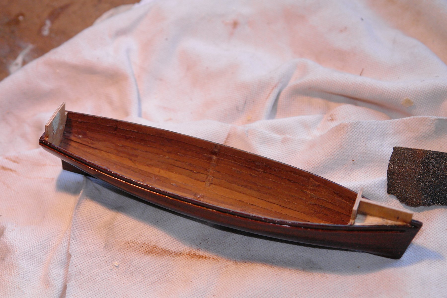
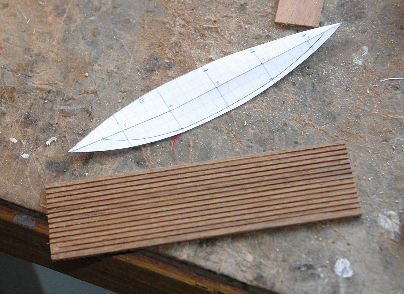
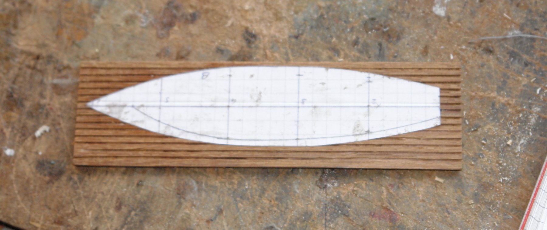
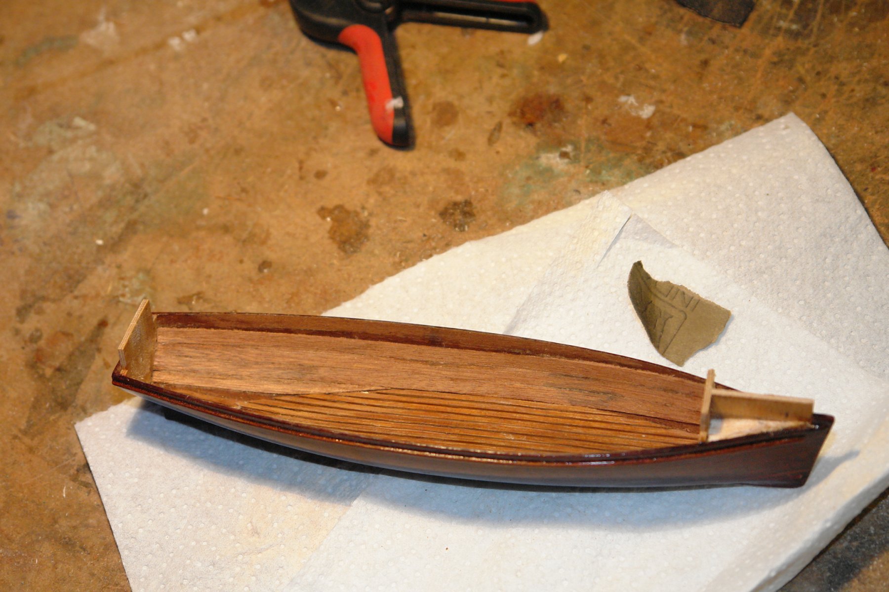
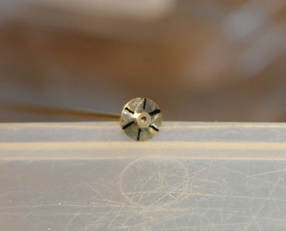
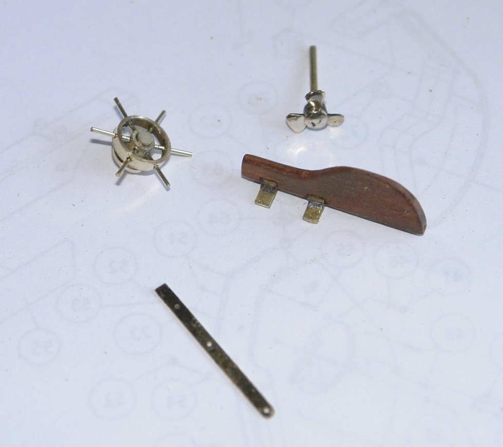
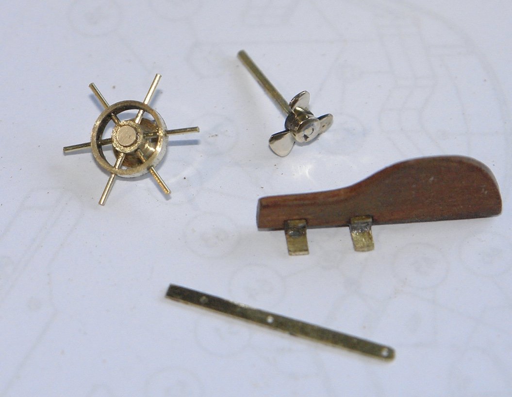
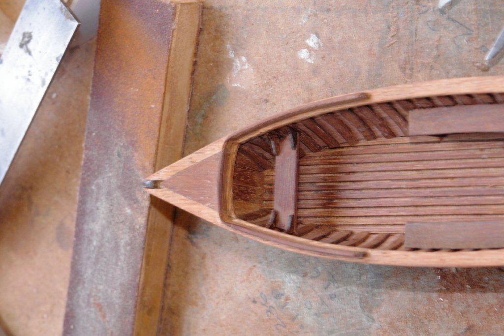
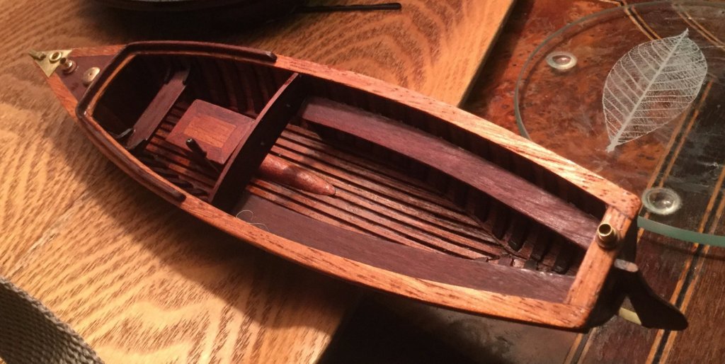
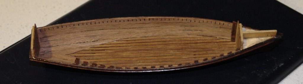
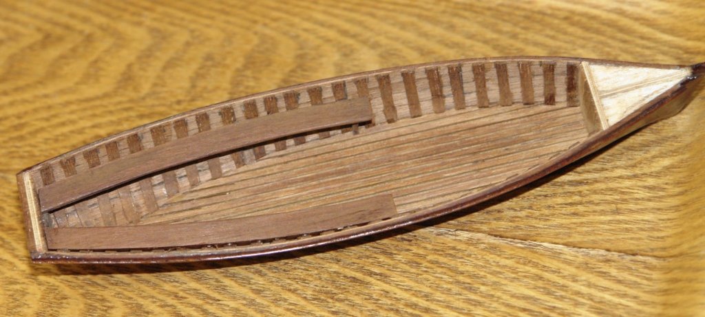
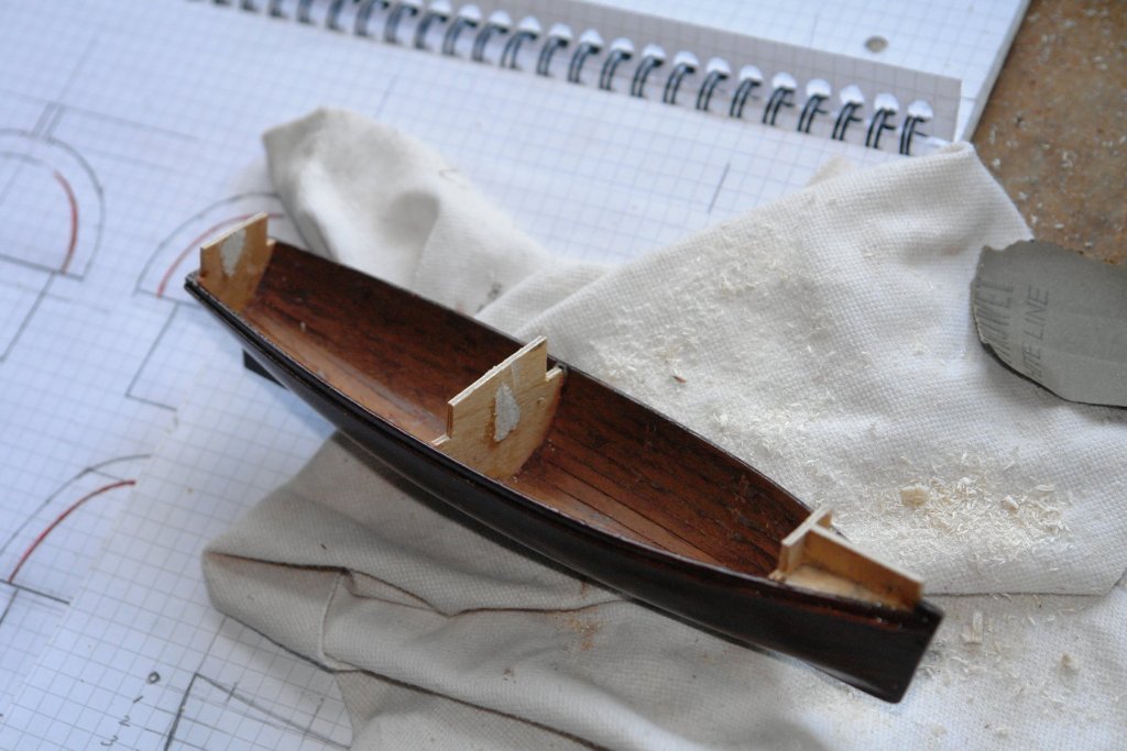
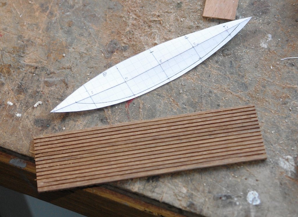
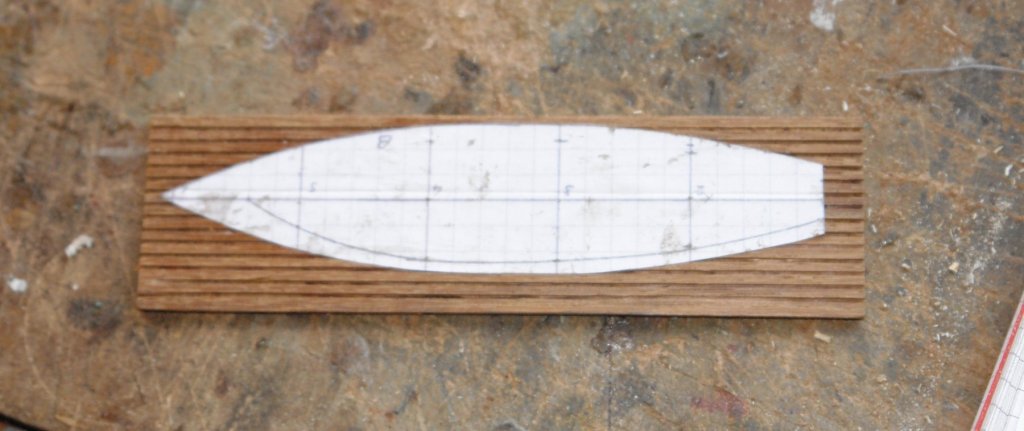
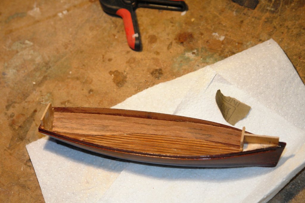
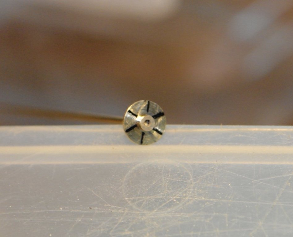
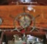
Pat, thank you for visiting and for your positive comments. I hope you enjoy reading the rest of the log. Update:- I have not had much time over the last few days but did get a bit done I cut the launch off the building frame. I had not waxed the frames to make detachment easy. Also I had purposely glued the planks on to the central frame as felt this would retain the planks in the correct position. Never the less the non-glued frames came away easily with a simple twist. The central frame was nibbled away with a pair of side cutters assisted by a small circular saw attached to the craft drill. It proved a fairly simple task. As previously explained I have little information on the launch but this is giving me a degree of freedom to innovate. I decided I wanted a flat slatted deck so I grooved a thin piece of mahogany and shaped it using the lowest horizontal hull section. Having glued the deck in place I decided that I would get a better internal finish by interior planking before simulating the ribs. I have not finished the internal planking because I got a bit distracted with a few fittings - the wheel, screw, rudder/brackets and the strap that runs from the keel to the bottom of the rudder. The screw was turned as a disc and then shaped with piercing saw / needle file. The blades were twisted with pliers. The screw about 0.3" external diameter. The wheel was made as a hoop and boss connected by 6 wire spokes For comparison purposes here is the rather poor picture I have of the real wheel. I hope to get back to building some time over the weekend.


-
Tools for Masts and Spars
KeithAug replied to JRB9019's topic in Modeling tools and Workshop Equipment
John - Have a look here for tool advice:- http://modelshipworldforum.com/ship-model-materials-and-tools.php Most good model shops carry a range of tools - In the UK I find this outfit to be a good supplier:- http://www.cornwallmodelboats.co.uk/acatalog/tools.html. I also use https://www.chronos.ltd.uk and find they give excellent service. Also this link gives an idea of the sort of tools others are using to make masts / yards:- http://modelshipworldforum.com/ship-model-masts-and-yards.php