KeithAug
-
Posts
3,986 -
Joined
-
Last visited
Content Type
Profiles
Forums
Gallery
Events
Everything posted by KeithAug
-
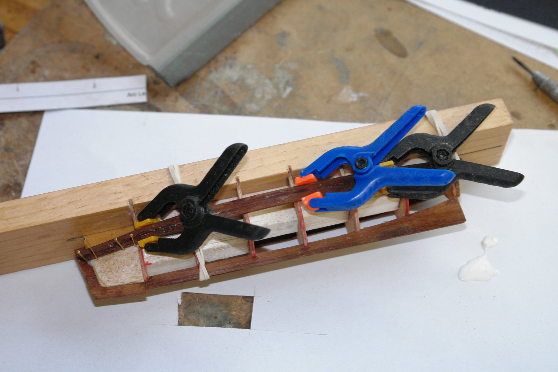
 Jon - I over bent the planks i.e. to a radius slightly smaller than I actually required. I applied PVA glue to the abutment edge with an artists paint brush before offering the plank up and clamping it in the middle. Clamping in the middle caused the bend to open up to a slightly larger radius and at the same time caused the ends to press against the frames due to the spring in the plank. I then applied other camps to lock the plank in position while the glue cured. The season assisted the glueing because we have a wood burning stove which roars away all day. It stands on legs with a 5 inch gap below it. The hull was placed in this gap to cure the glue as each plank was laid. The curing time was about 30 minutes. Good luck. Pawel - thank you. And thank you to everyone else who has viewed my log.
 -
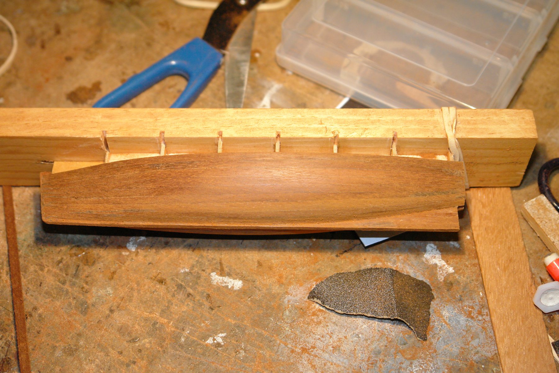
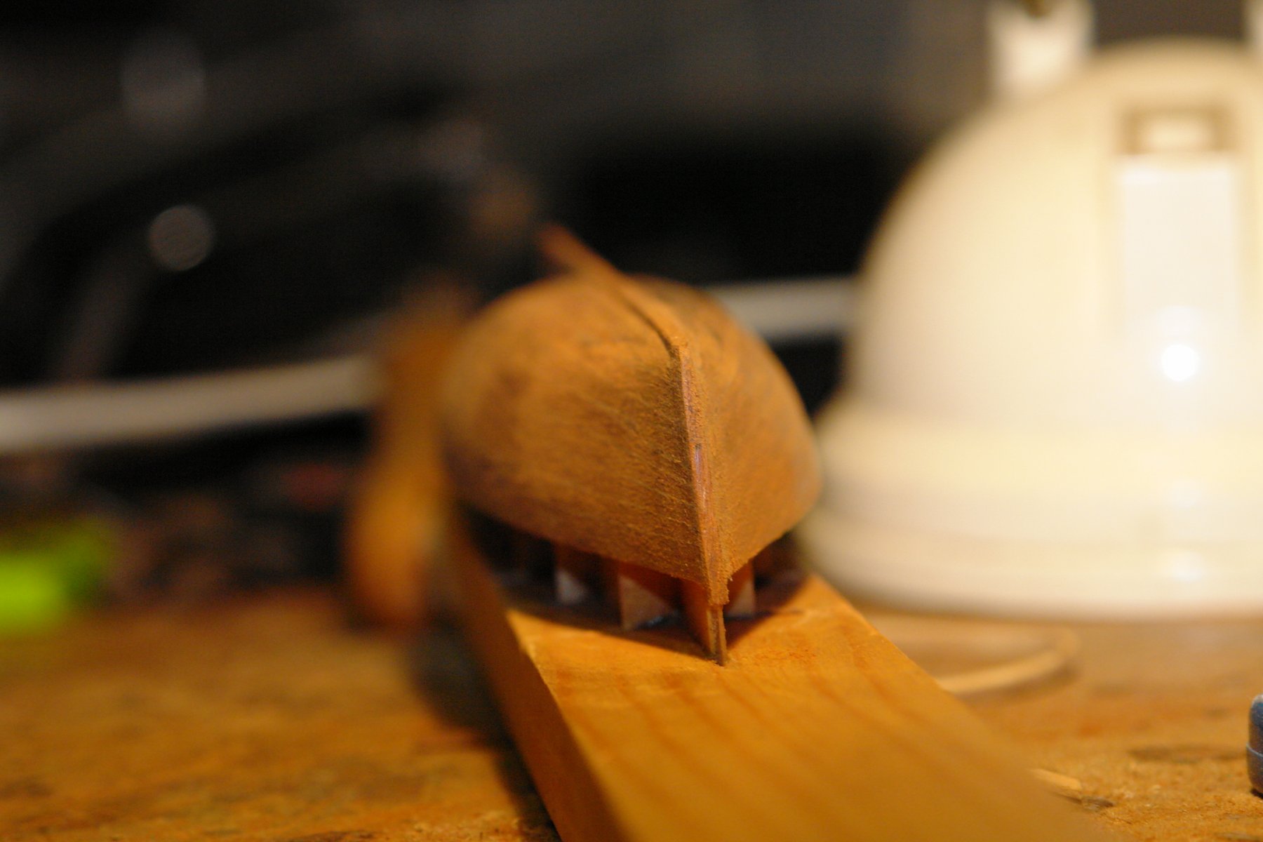
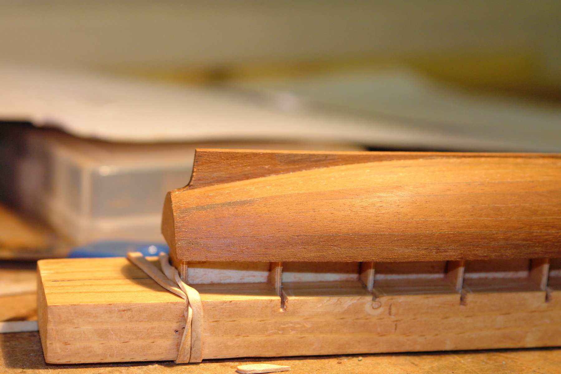
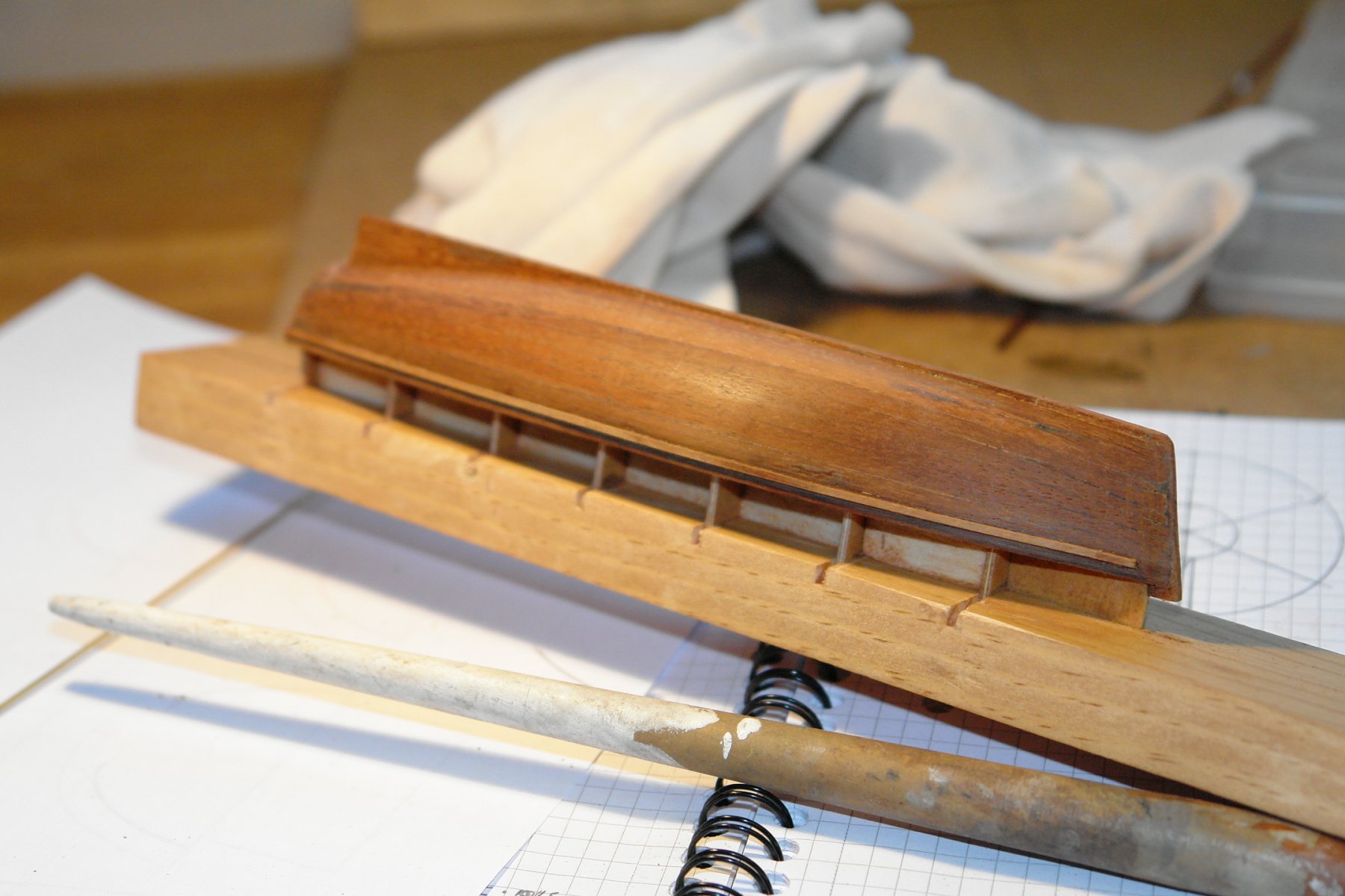
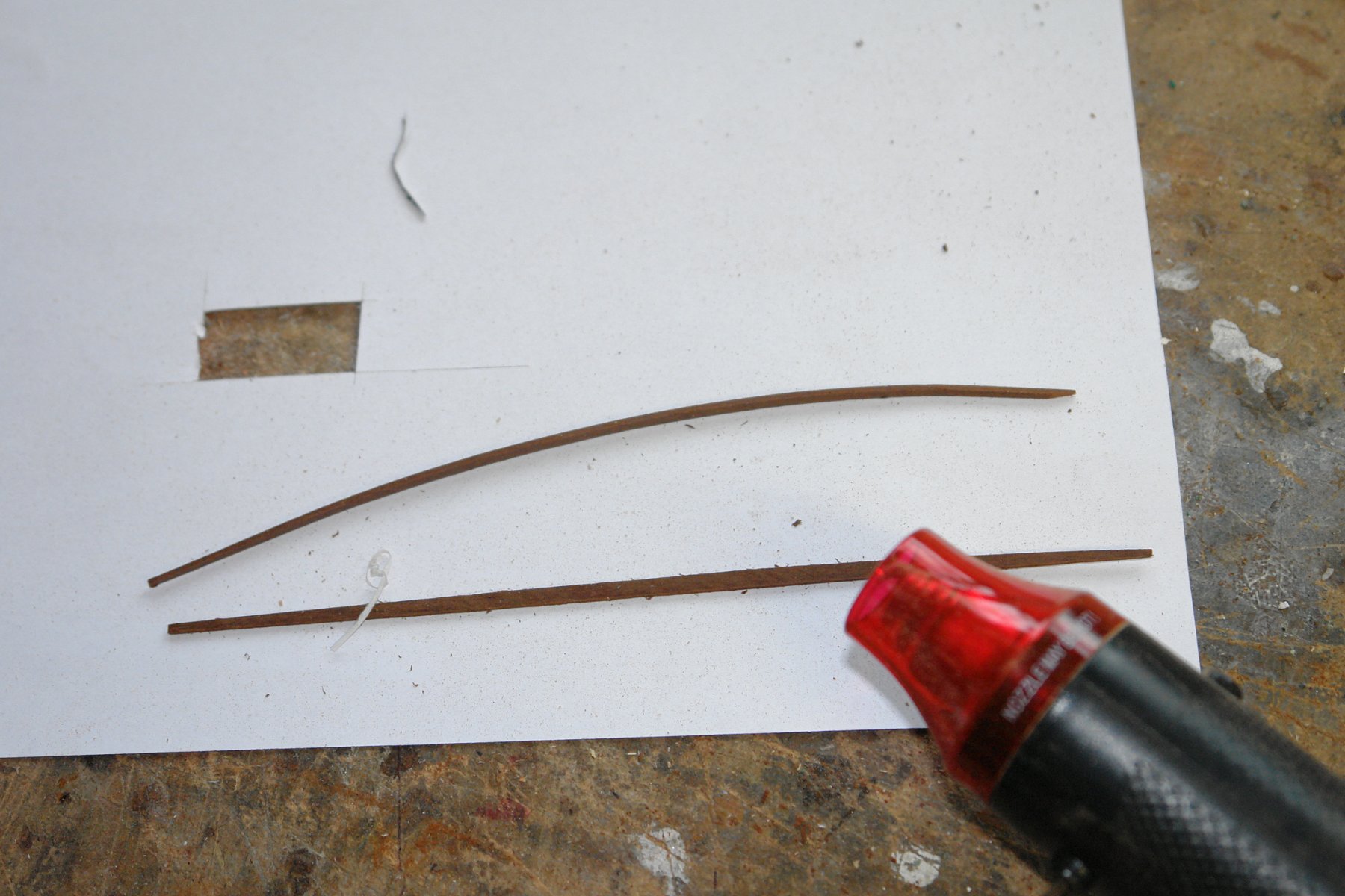
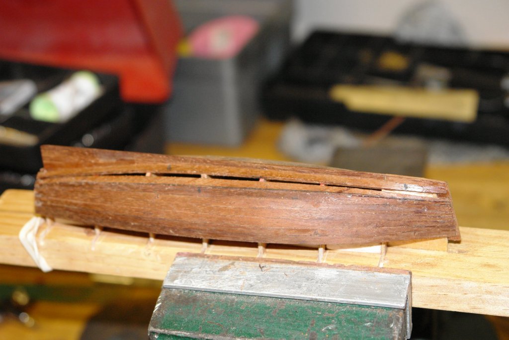
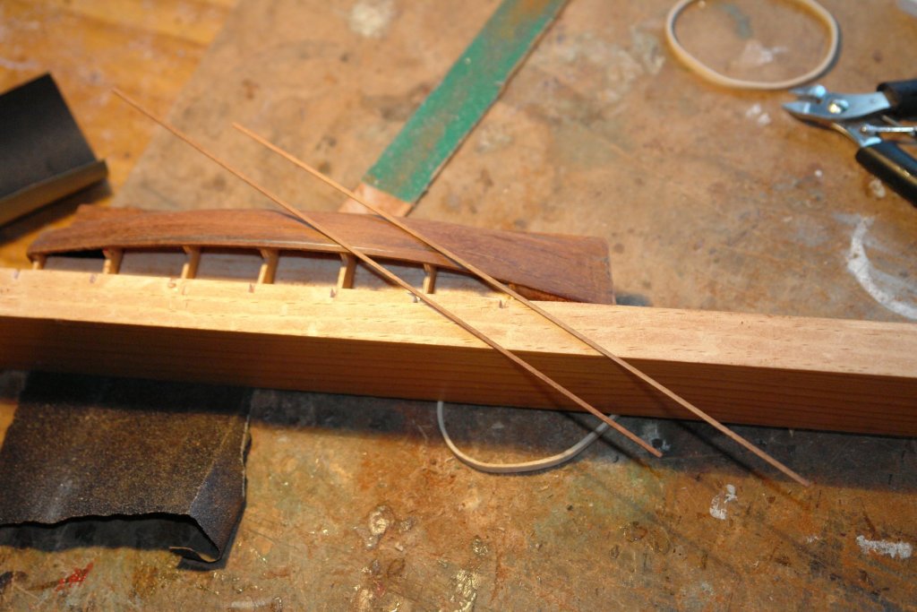
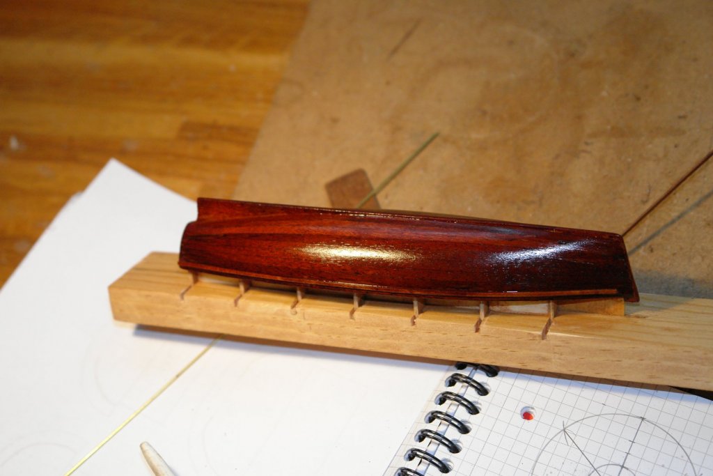
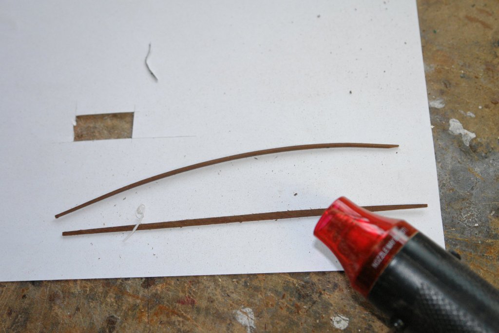
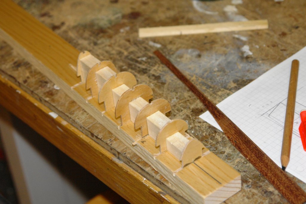
I seem to have missed a few posts - my build seem to have descended into a mess of puddings. Thank you all for your contributions - I will try to answer the points raised. Jon - good luck with trying the plank method - the following post will show how it turned out. John - my wife makes her own pudding to a recipe passed down from her ancestors (served with brandy butter). Best not to dwell on what goes into the pudding but it tastes wonderful. The heat gun I am using was bought cheaply off Amazon (sold for hobby use). I am using it directly on the wood without any wetting. Per - agreed the hot air gun is a great tool. So to continue. I continued planking down the hull until I got to the position in the next photo, I then attached the garboard planks - leaving a gap of just under 2 plank widths to fill. Both the fill planks had to be individually shaped - on the bench sander and then by hand sanding. I then cut down the keel to finished size and sanded the hull to remove imperfections. The profile of the back of the keel was cut to take the screw. I then did some final sanding with 400 grit wet and dry (used dry). Rubbing strips were cut to add to the hull (.040" x .040" section). Finally the launch got its first coat of poly. I'm pleased with the shape given my starting point was some improvised and hand drawn sections.


- 882 replies
-
- 12
-

-
And to you too Tecko. The project is developing really well. Very interesting.
-
Thank you Michael. I hope you are recovered enough to enjoy Christmas dinner. The pudding is already resting very heavily in the stomach over here and I never want to see another Brussel sprout. Thank you to all who have hit the like button and for those of you about to sit down to your meal my advice is "beware of the Christmas pudding".
-
Nice progress John. Loved the detail - especially the bailer. Sorry no I have no relevant knowledge to help your deliberations.
-
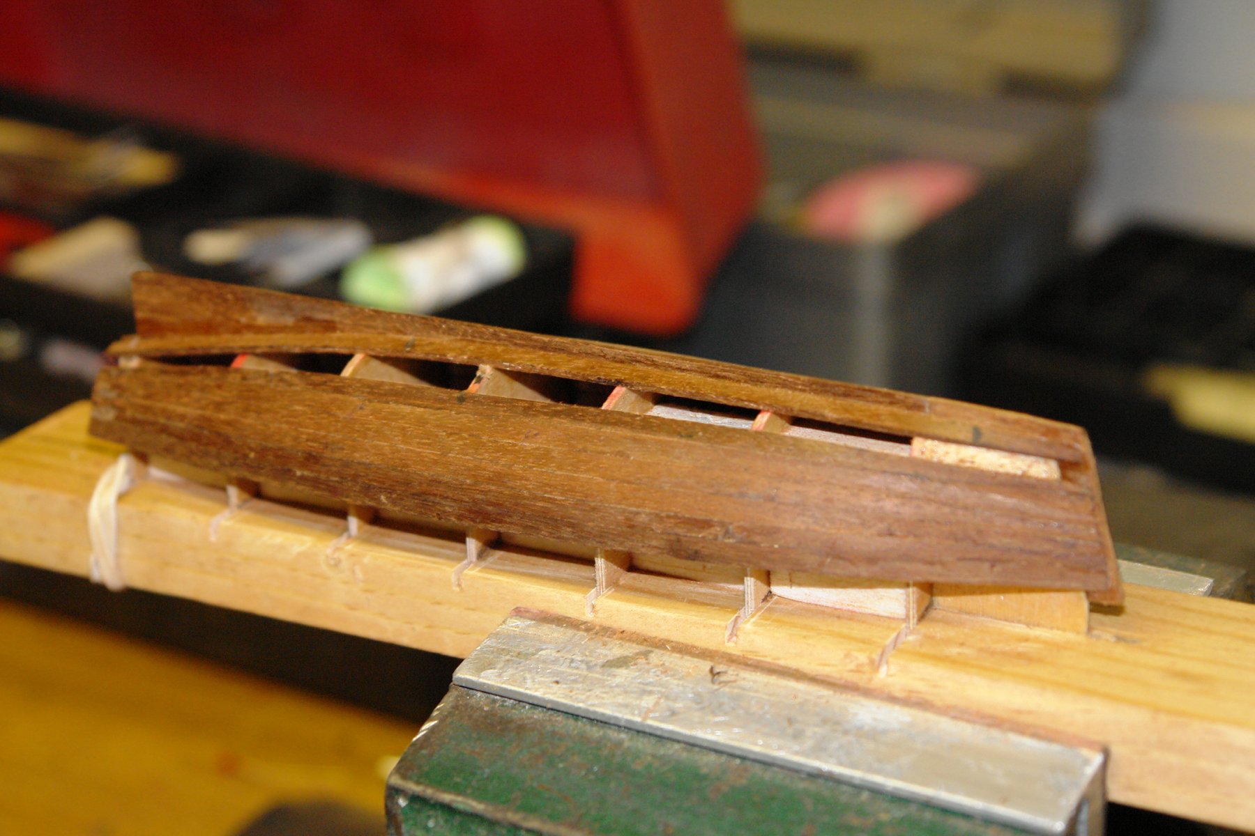
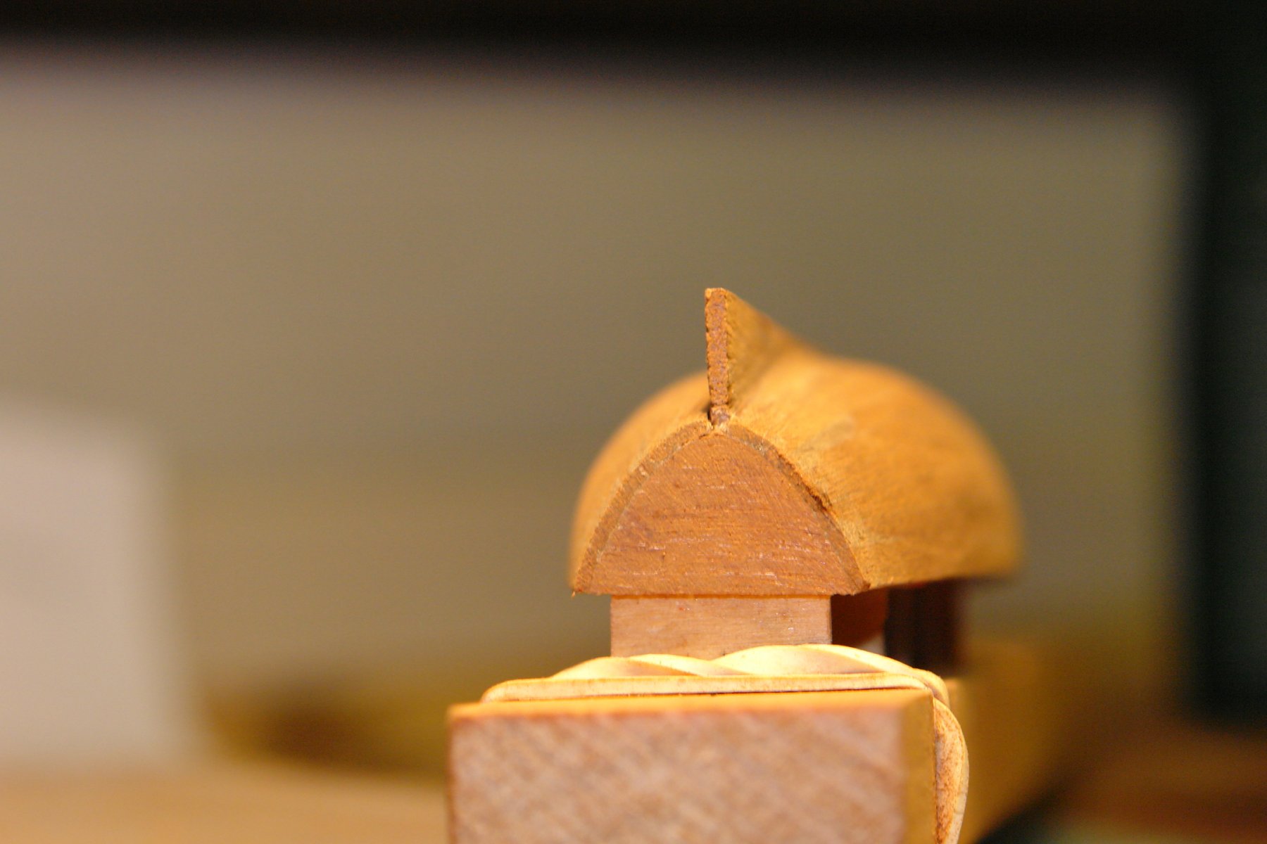
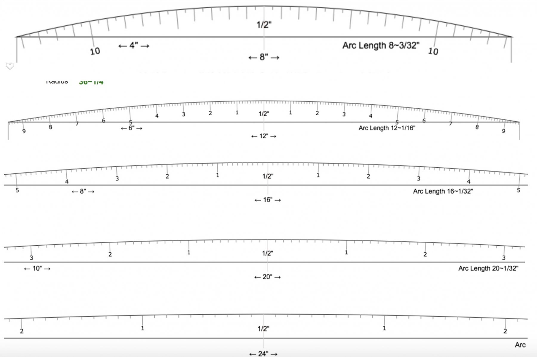
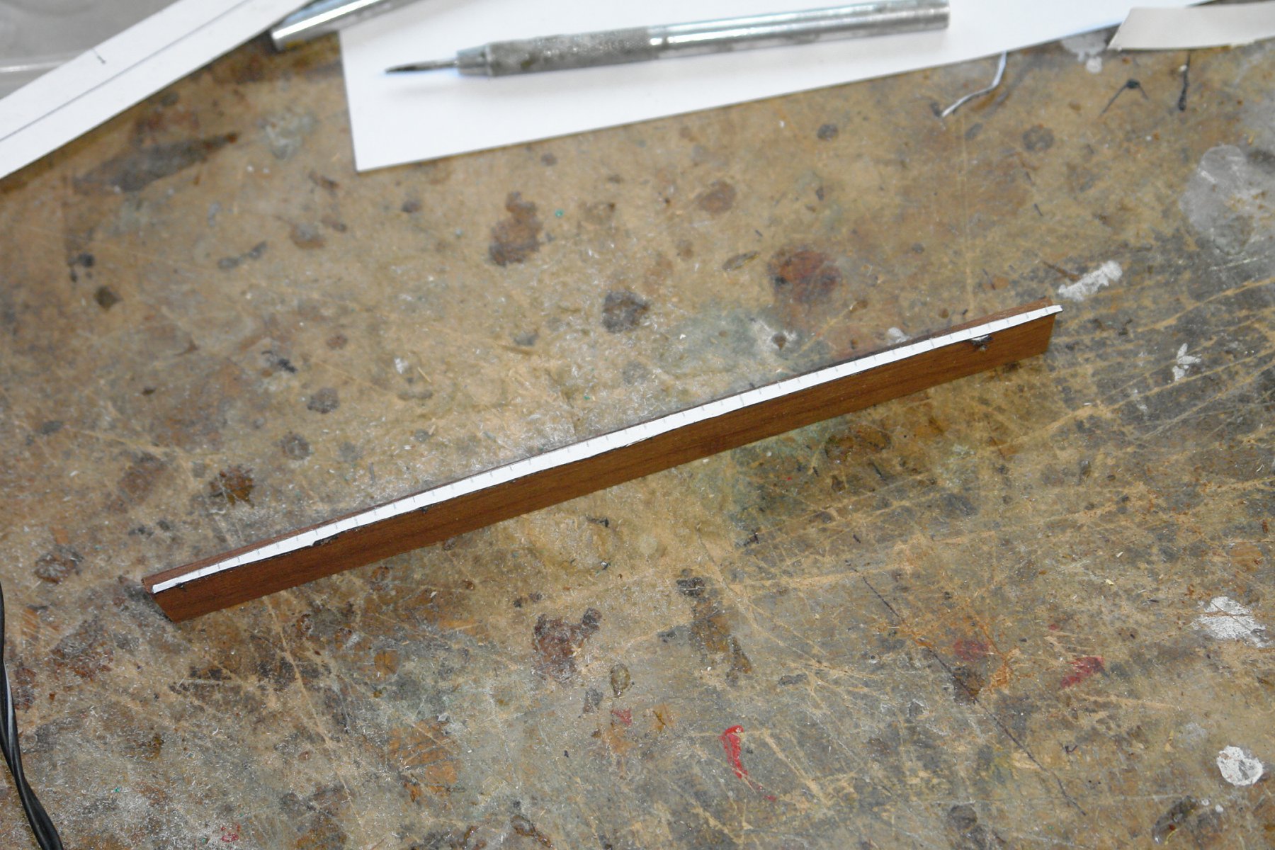
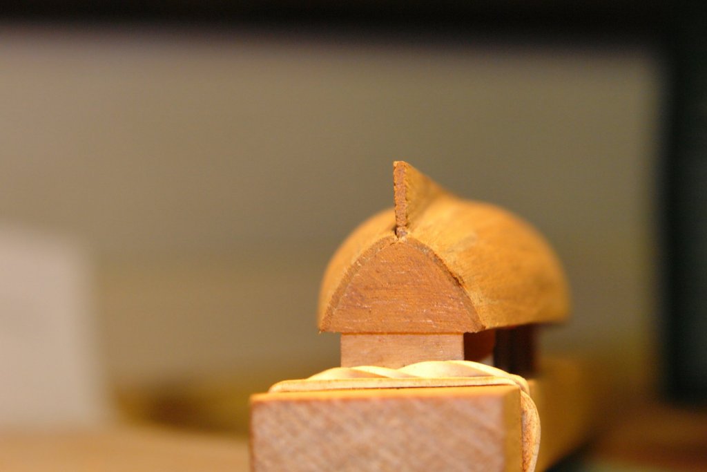
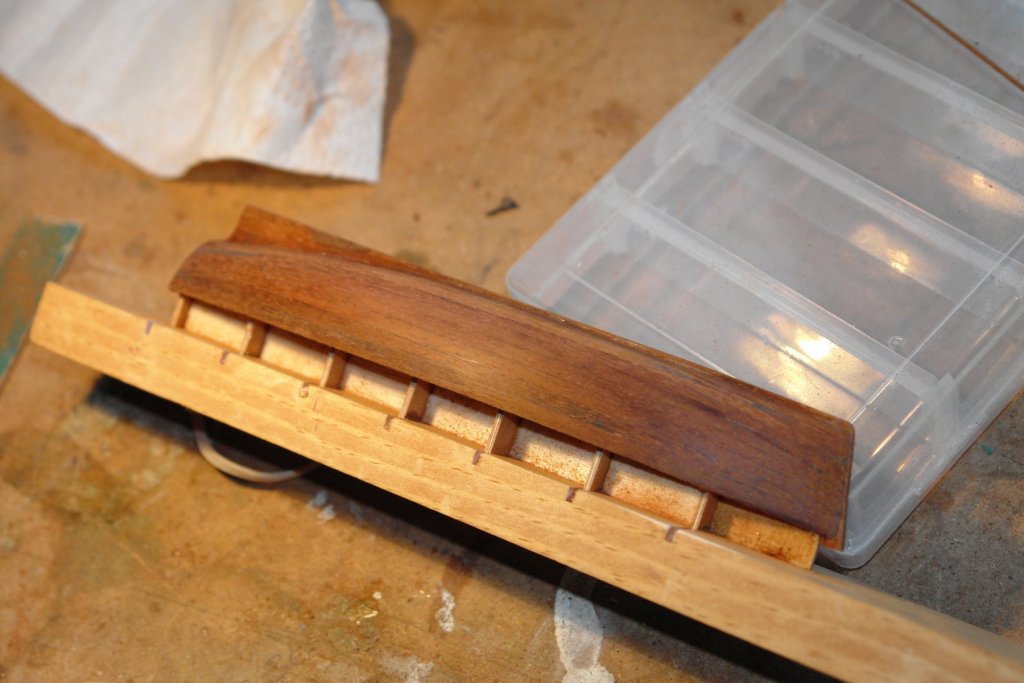
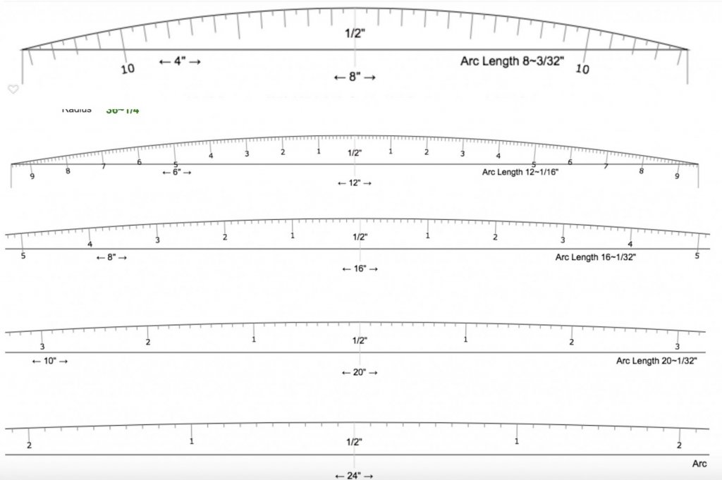
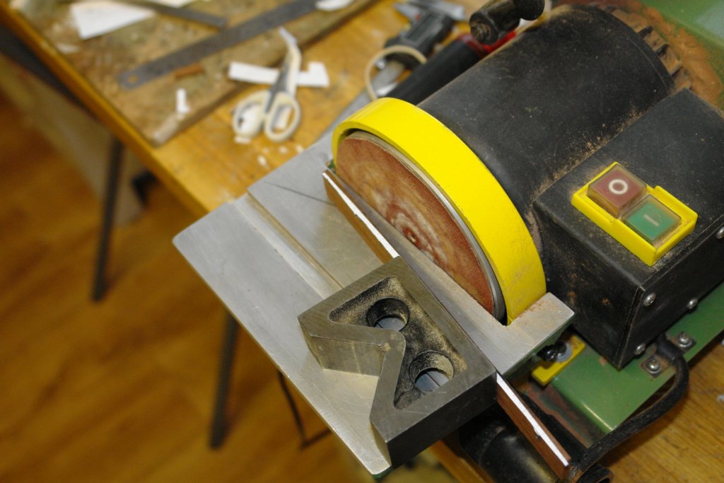
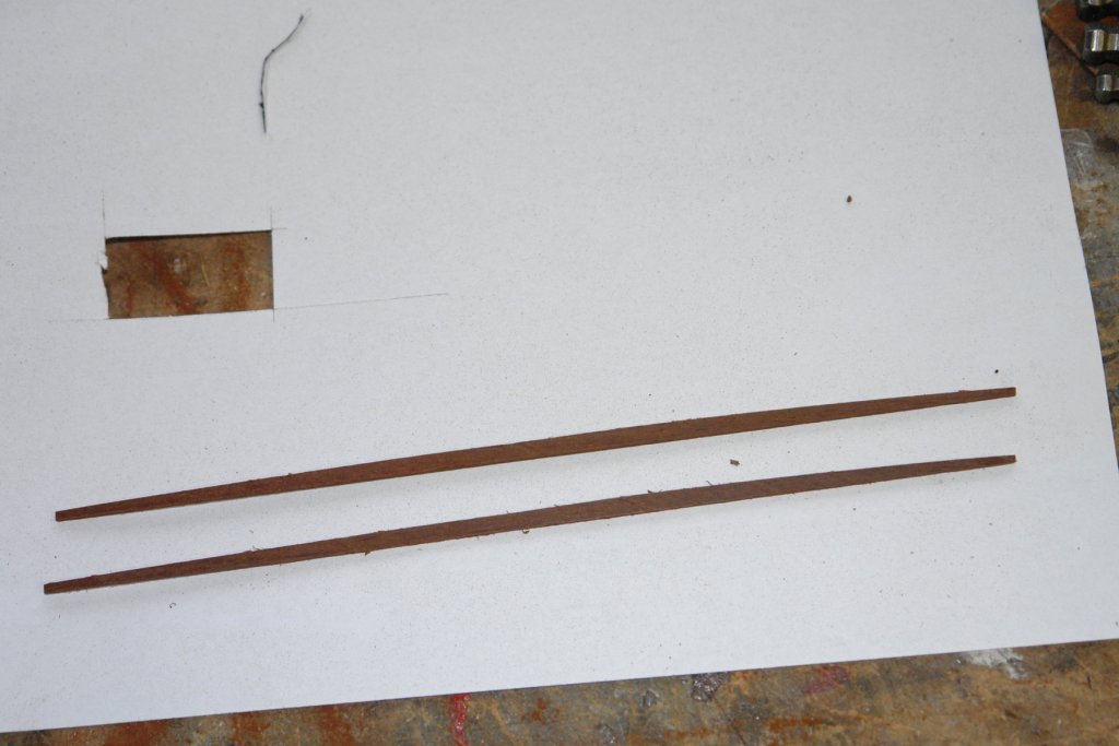
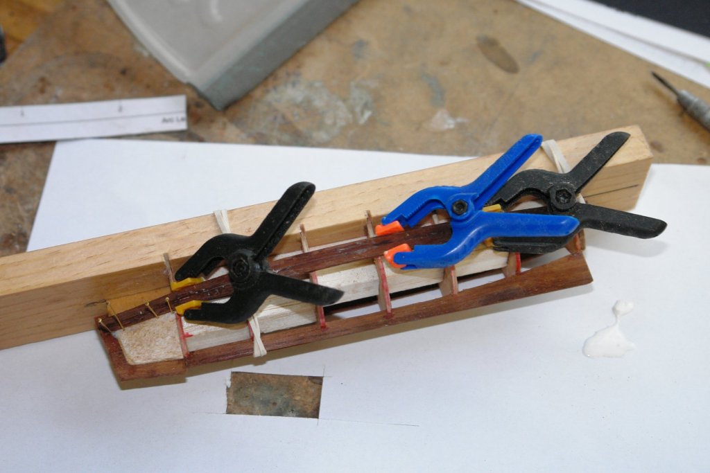
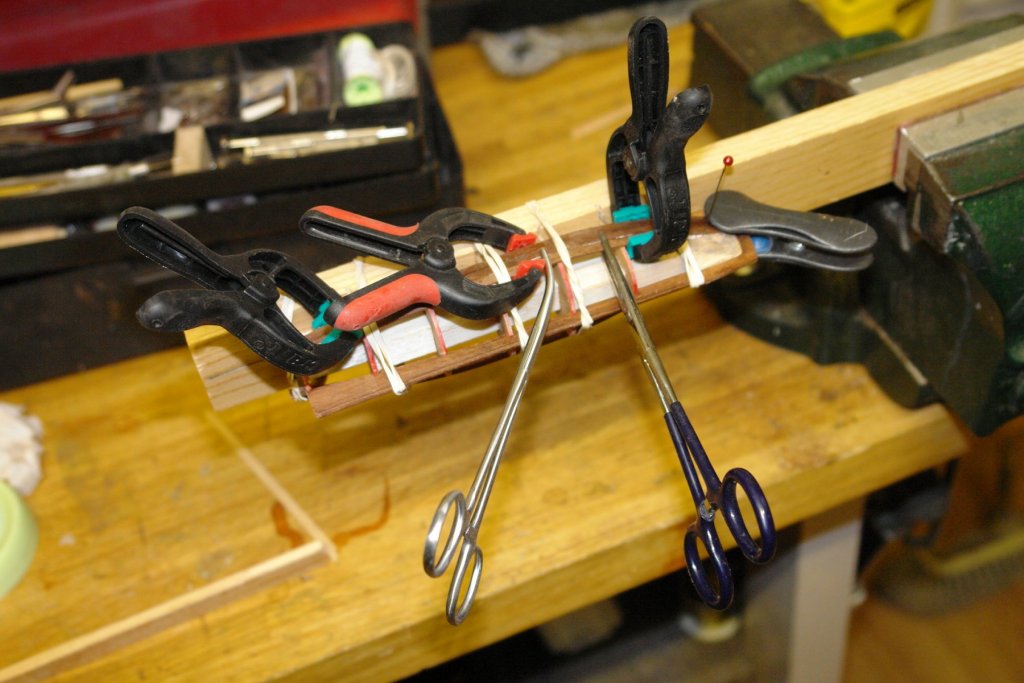
Thank you Dan - I think I have seen others use the magnet trick. Thank you Tom. Thanks to everyone for all the likes. So to continue with the launch (the guests are proving less disruptive than expected). I put the former for the bow in place and installed and shaped the bow filler blocks. The former was then edged with mahogany to form the continuation of the keel and the stem. The 2 parallel upper hull planks were then installed. The keel / stem have yet to be cut down to their finished size. I adopted a novel (simplified) method of making the remaining planks. Rather than individually shaping planks I went for the mass production approach. I measured the required length at the waist and stern and then used the ratio to determine how much wider the planks needed to be at the waist. I then downloaded a series of arc profiles from the web and printed them out. I cut the raw stock for the shaped planks - a piece of mahogany 7"x 0.75" x 0.125". I then selected an arc that gave me the desired waist and edge thicknesses on the 7" x .125" edge. I then used double sided tape to paste the arc on to the edge. I then sanded away the edge to form the required plank shape. The sanding was done on the disc sander, employing a "V" block to keep the plank vertical while shaping. Identical .040" width planks were then slit off on the Byrnes saw. The planks were bent using heat from a hot air gun - a very effective process that I will use in future - no more messing around with steam or hot water for me. Planking of the hull then progressed. Sometimes with many clamps and elastic bands. So far (half way) its woking out well (nice water tight joints). This is definitely my last pre Christmas post. I'm looking forward to what Santa might bring. HAPPY CHRISTMAS to you all.

- 882 replies
-
- 10
-
-
Merry Christmas to you all Kevin.
-
Stevenson's ER32 Collet Blocks
KeithAug replied to KeithAug's topic in Modeling tools and Workshop Equipment
John, You need to think about getting something with a decent sized hole through it to take longer stock. Not all round collet holders have a decent bore. The ER collet blocks work fine in the lathe chuck if you are wanting to quickly mount something that isn't going to damage a finished surface of softer bar stock such as aluminium or brass (the 3 jaw chuck can damage these quite easily). If you don't want to go through the bother of dismounting and remounting the chuck then the collet blocks are a quick and easy solution and do have a decent bore. It isn't as accurate as a collet chuck but I checked my set up and can get concentricity of better than .002" which is good enough for most of what I do. I do have a collet chuck which I use for more accurate work. If you need smaller then you can get ER25 versions. -
John. Don't mention the cricket, or rugby league for that matter. Much better to mention Rugby Union. Have a happy Christmas.
-
Michael - hope you are better for Christmas day - its miserable when you can't ask for more pudding.
- 749 replies
-
- 2
-
-
- albertic
- ocean liner
- (and 2 more)
-
Its all looking very professional. Impressive.
-
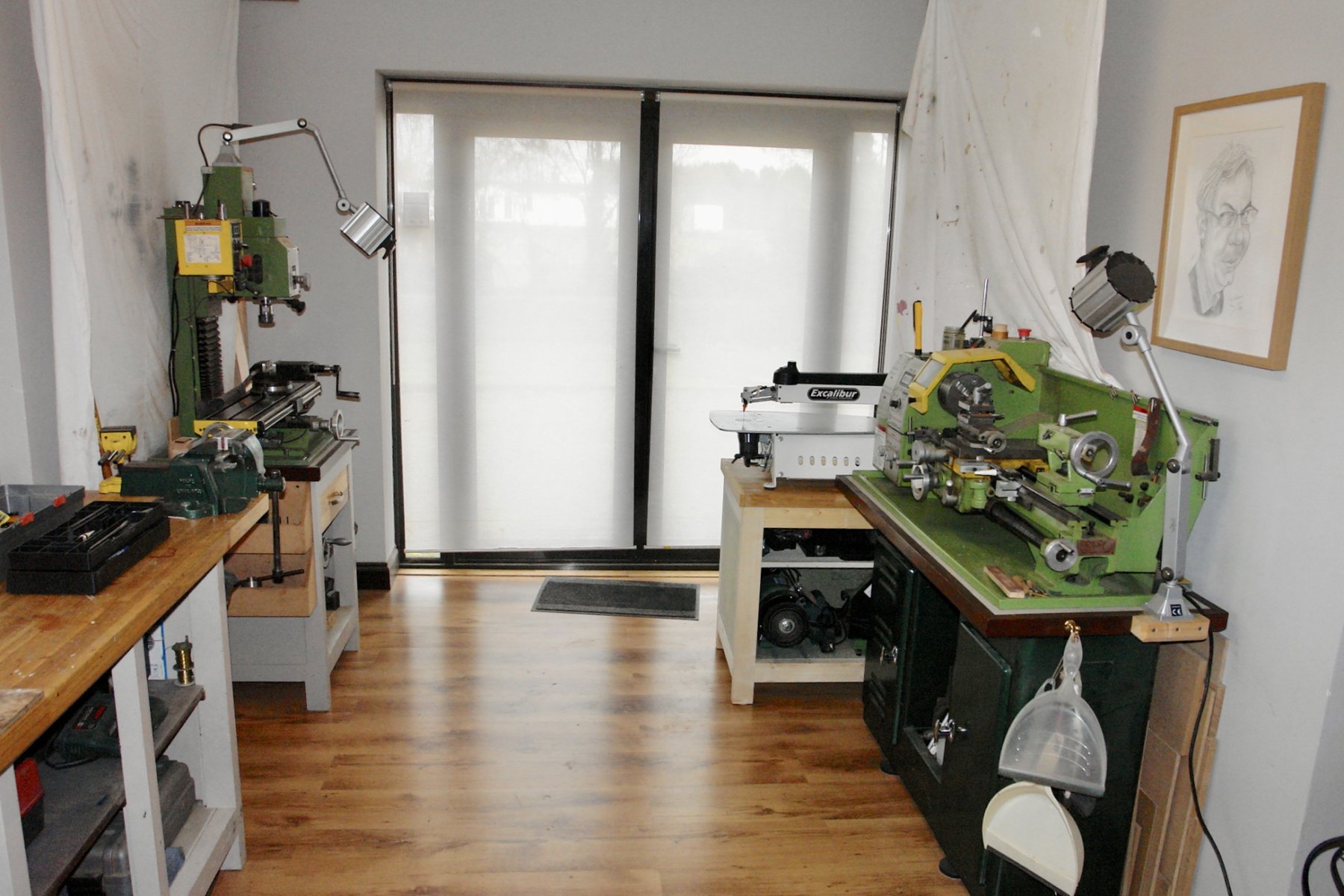
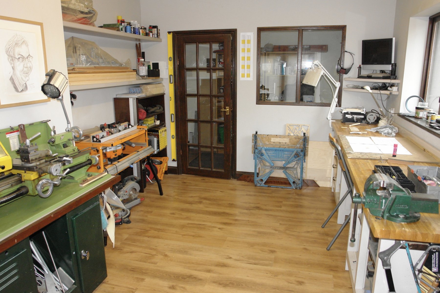
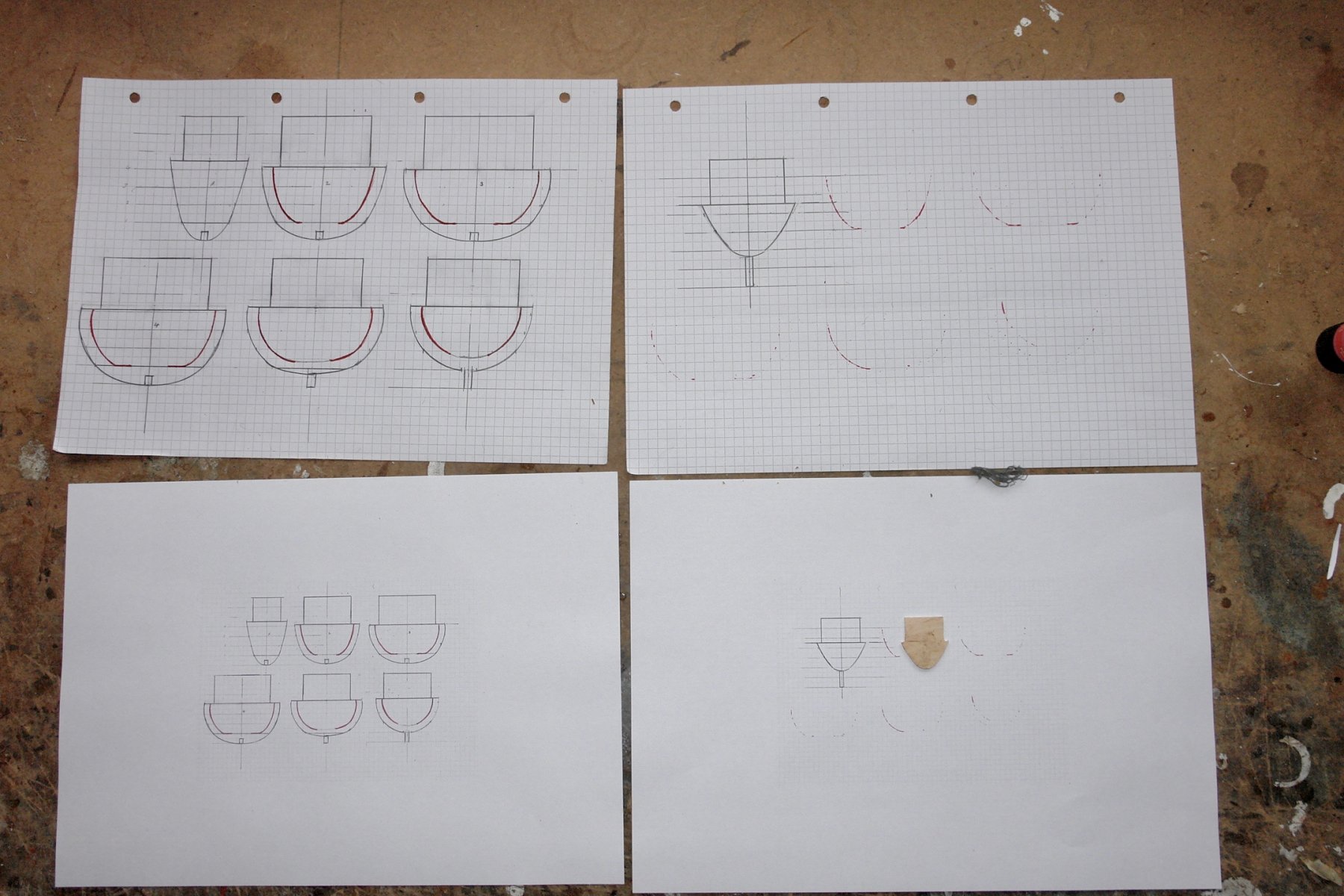
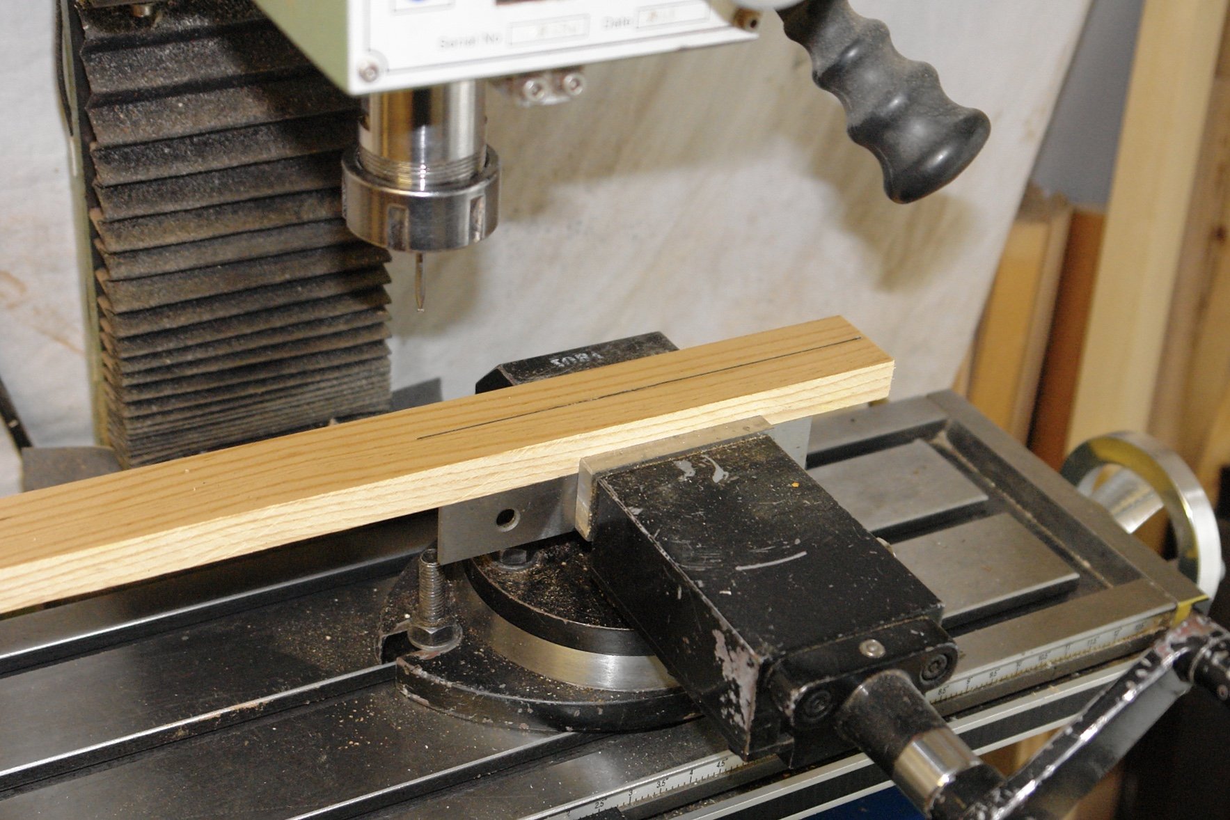
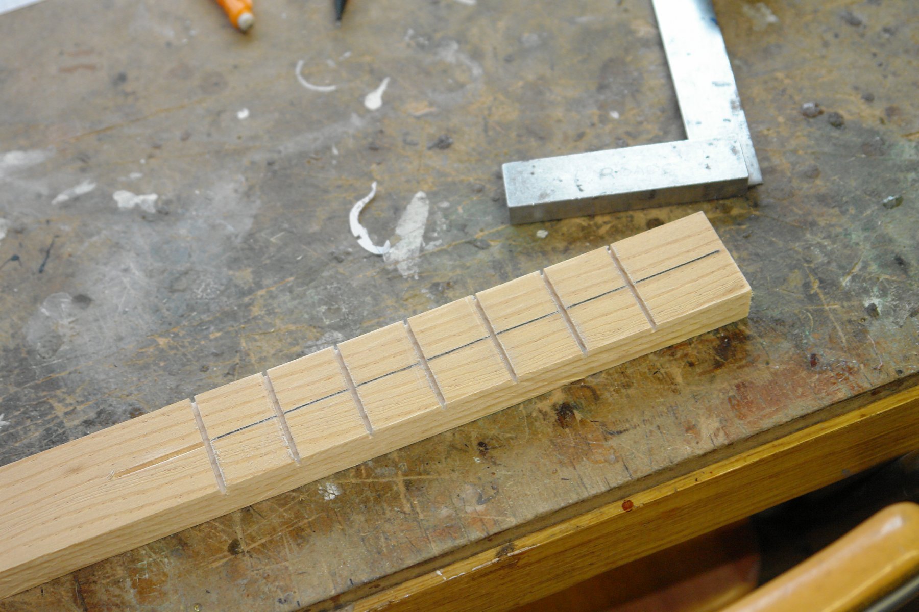
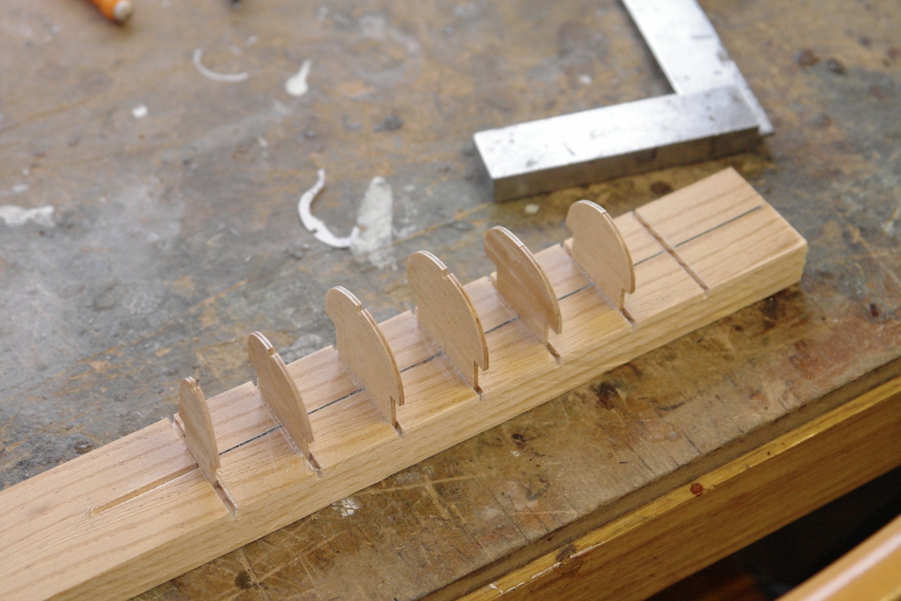
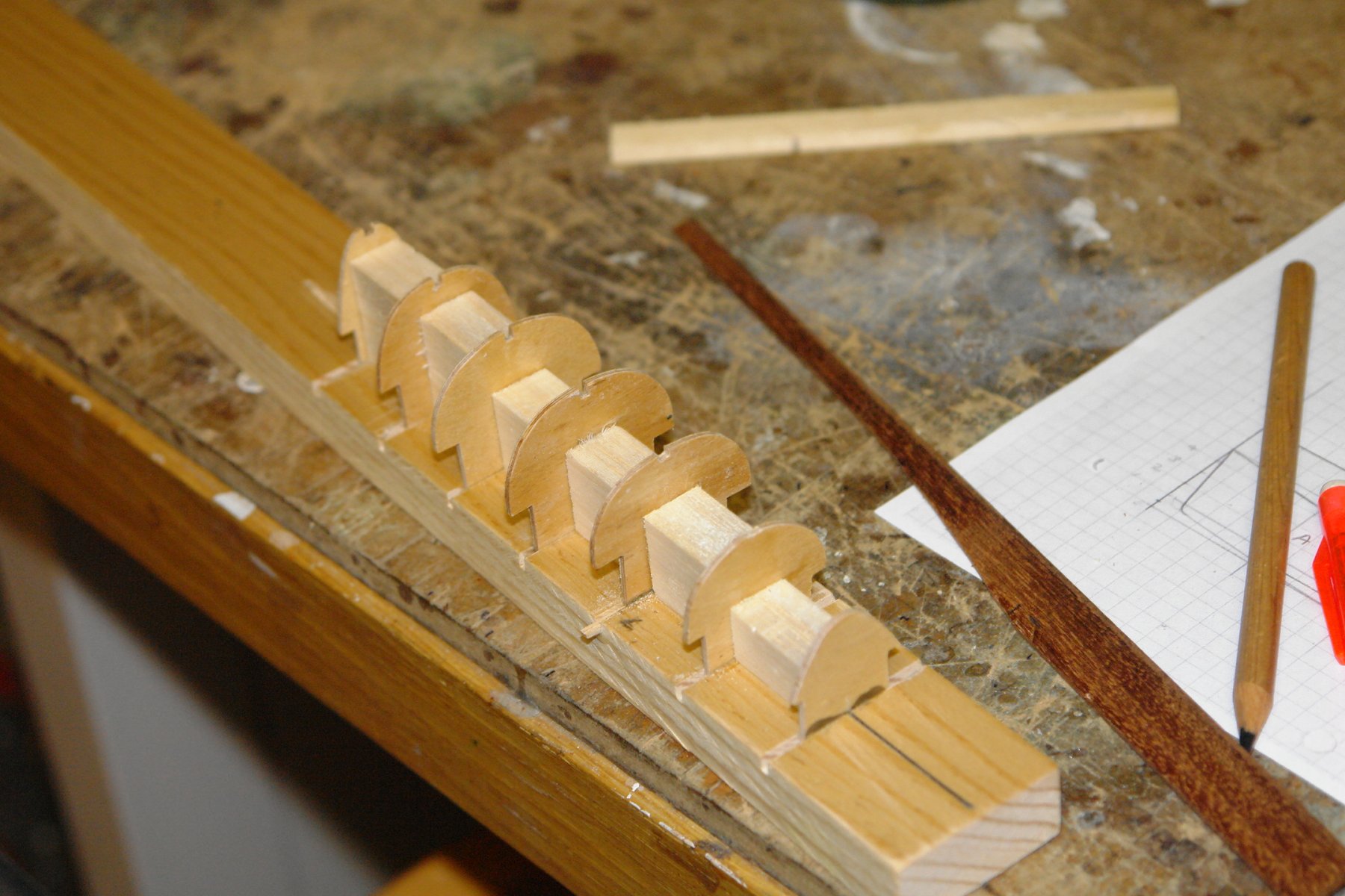
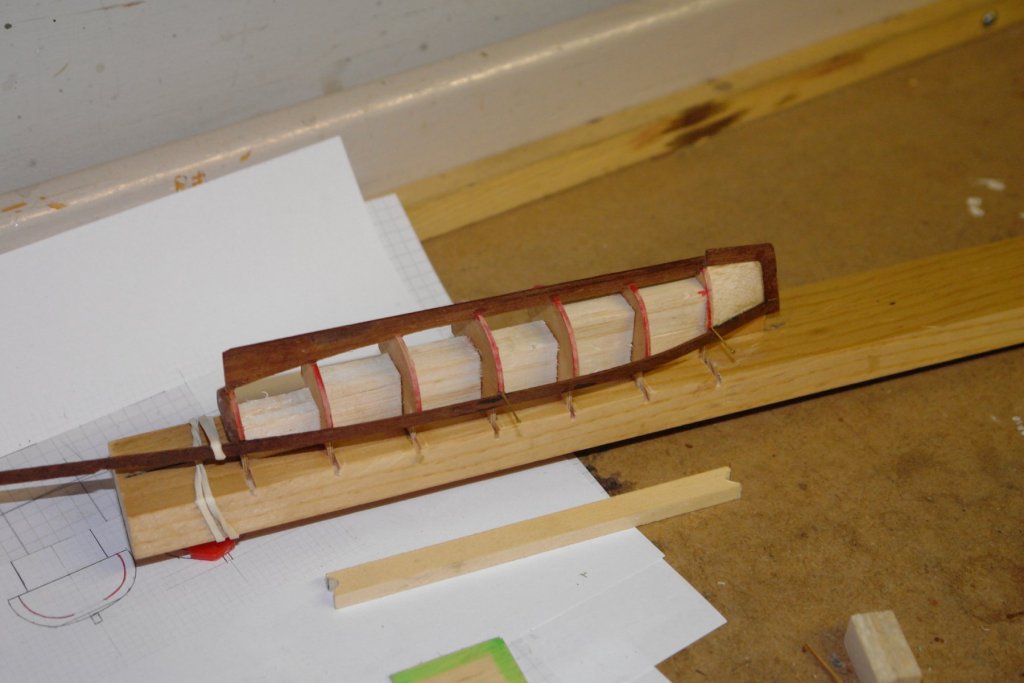
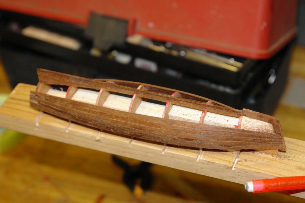
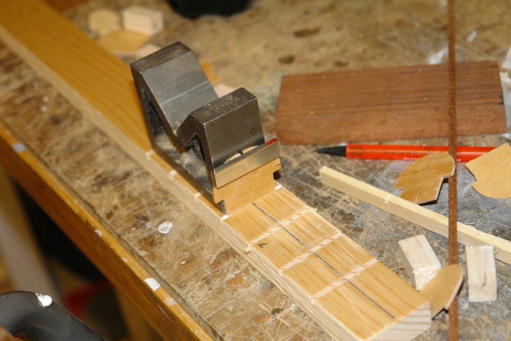
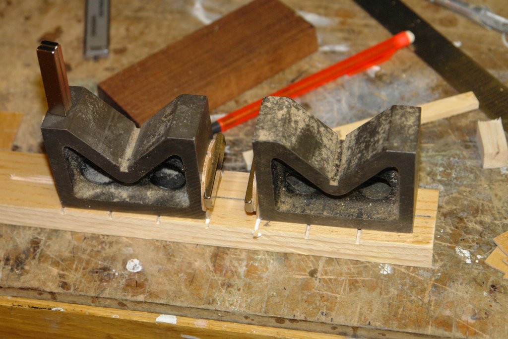
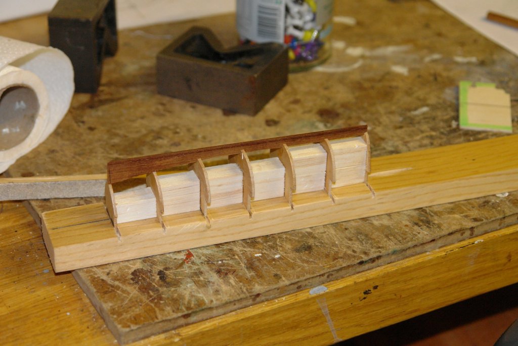
Sometimes when I am about to start a new element I find myself getting frustrated with the state of the workshop. This happened on Sunday so I spent the day tidying up. That done I was forced to make a start on the launch. I redrew the sections at twice scale to get them as well defined as possible. I then reduced them to scale size on the printer. The launch is about 7 inches long and 1.6 inches wide. I made a test section to have a little practice on the scroll saw - bottom left quadrant. The sections are just formers and will be removed once the hull is planked. I then made the base board on the mill - the slots are .080" i.e. the thickness of the ply sections. I found cutting the sections on the scroll saw quite challenging. It took a great deal of concentration to keep the cut on the line. This was predominantly because the cut line looked almost identical to the black drawn line I was following. As a result I struggled to see where along the line the blade actually was. Next time I will draw the line I am following in another colour - probably orange (dark enough to see, light enough not to blend with the black slot of the cut). Taking the cut slow and steady produced acceptable results - the frames temporarily fitted in the next photo are as cut. The frames were squared up and glued using the right angle edge of some "V" blocks. They were clamped while drying using rare earth bar magnets (3mm x 10mm x 40 mm). With the 7 frames installed a keel was made and glued in the pre cut notches. The keel is much deeper than needed and will be cut back later. Balsa blocks were glued between the sections to add stiffnes during planking. I am thinking of single planking in mahogany of .125" x .040" section. I have to admit that i'm not entirely sure what I am doing. Its all bit of an experiment. Oh Hummm! I may not get another post done before Christmas as the house is already in entertain guests mode. So if I don't can I wish you all the compliments of the season.


-
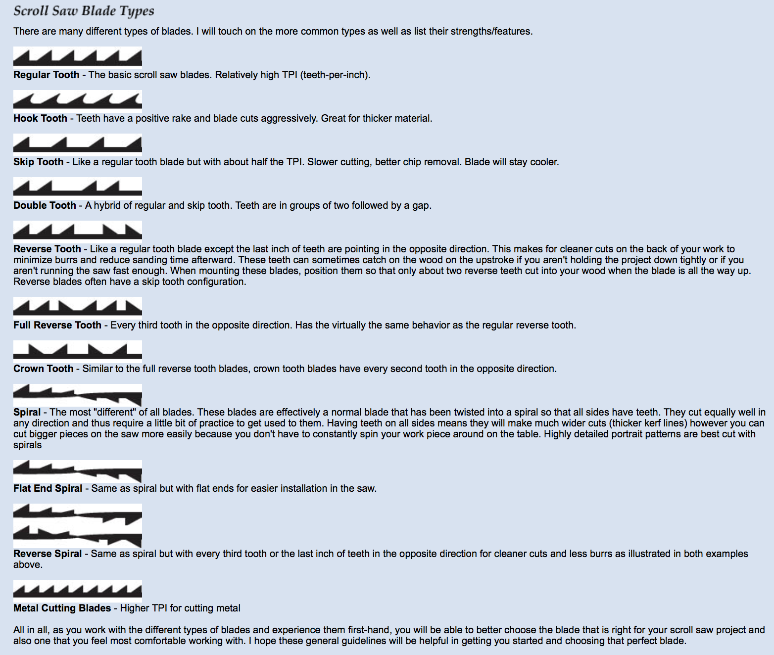
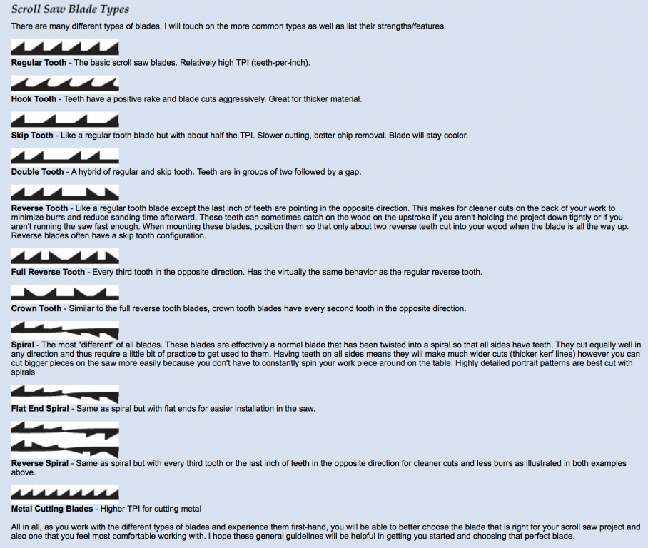
This is a better scroll blade chart:- http://www2.woodcraft.com/PDF/Olson-scrollblade-chart.pdf
-
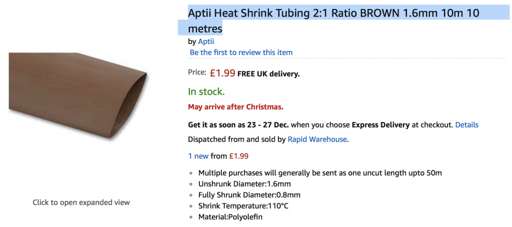
Hello Mark I got the heat shrink from Amazon. I got the smallest diameter possible 1.6mm pre shrunk 0.8mm shrunk.
-
Michael thank you. Not quite as heavily built as your coffee table. Jon / Noel:- I had a practice with the saw today. It came with a lot of blades - the first pulled as you described but the second (a much finer blade) didn't. I'm pretty sure I had both the right way round but its difficult to check - in the end I got the jewellers loupe out to check. That said there are a lot of blade types - most of which I have as they came with the saw. It will take a while to try them all.
-
Dan. What an amazing job you are doing and a good read as well. I’m still wondering how it is possible to get such detail at this scale. Wishing you a Happy Christmas and a prosperous New Year.
- 287 replies
-
- 3
-
-
- michelangelo
- ocean liner
- (and 1 more)
-
They are looking pretty smart Michael. Have you recalculated your hourly rate recently? It must be dropping like a stone.
- 749 replies
-
- 5
-
-
- albertic
- ocean liner
- (and 2 more)
-
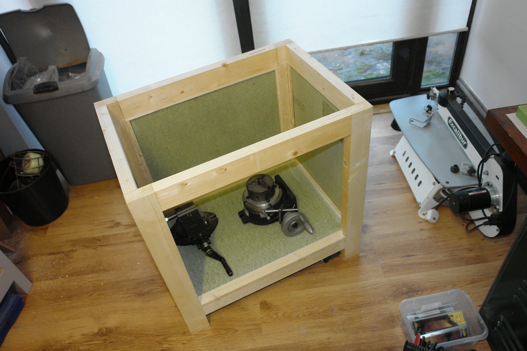
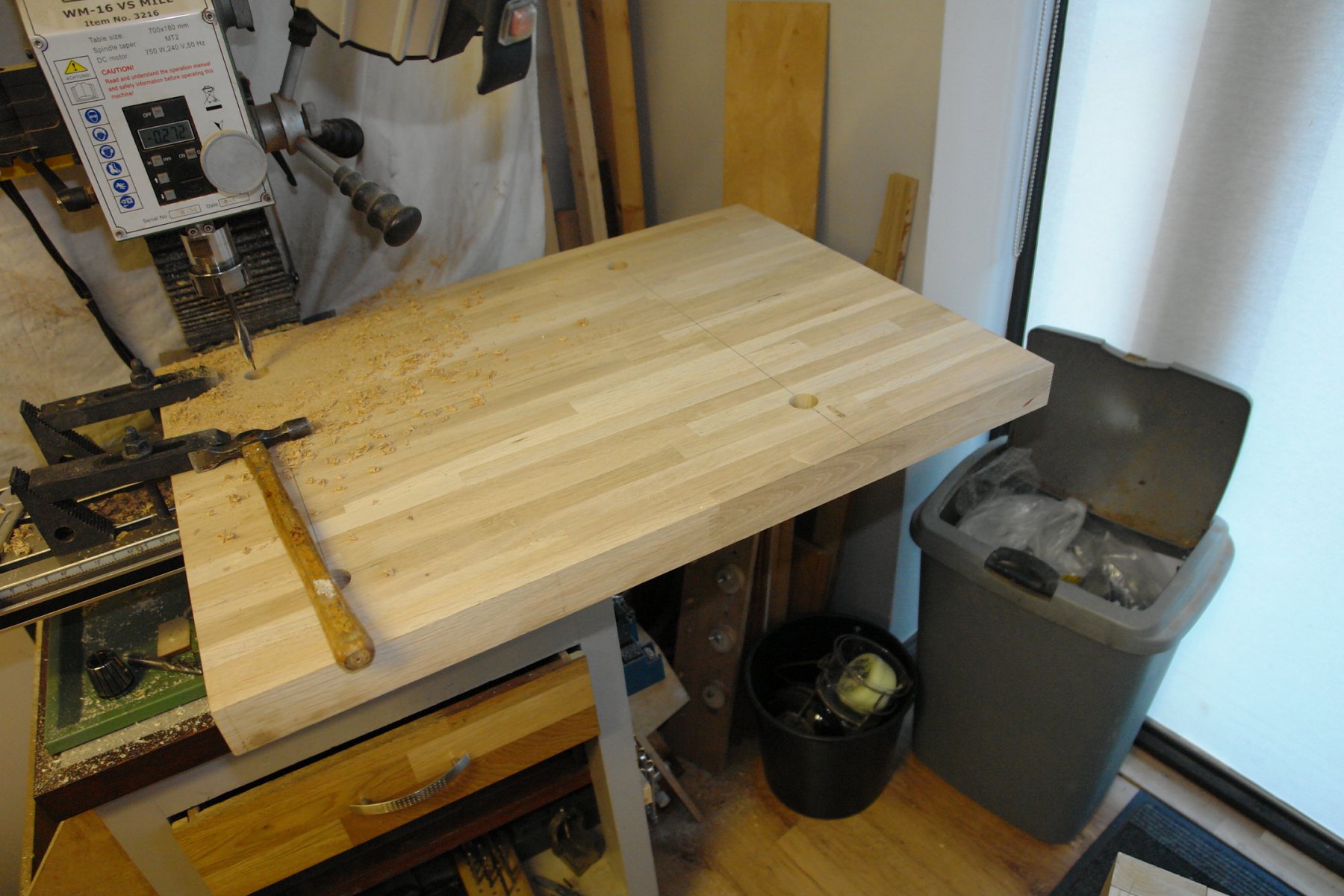
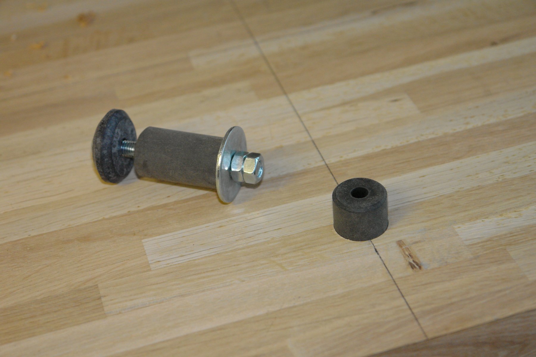
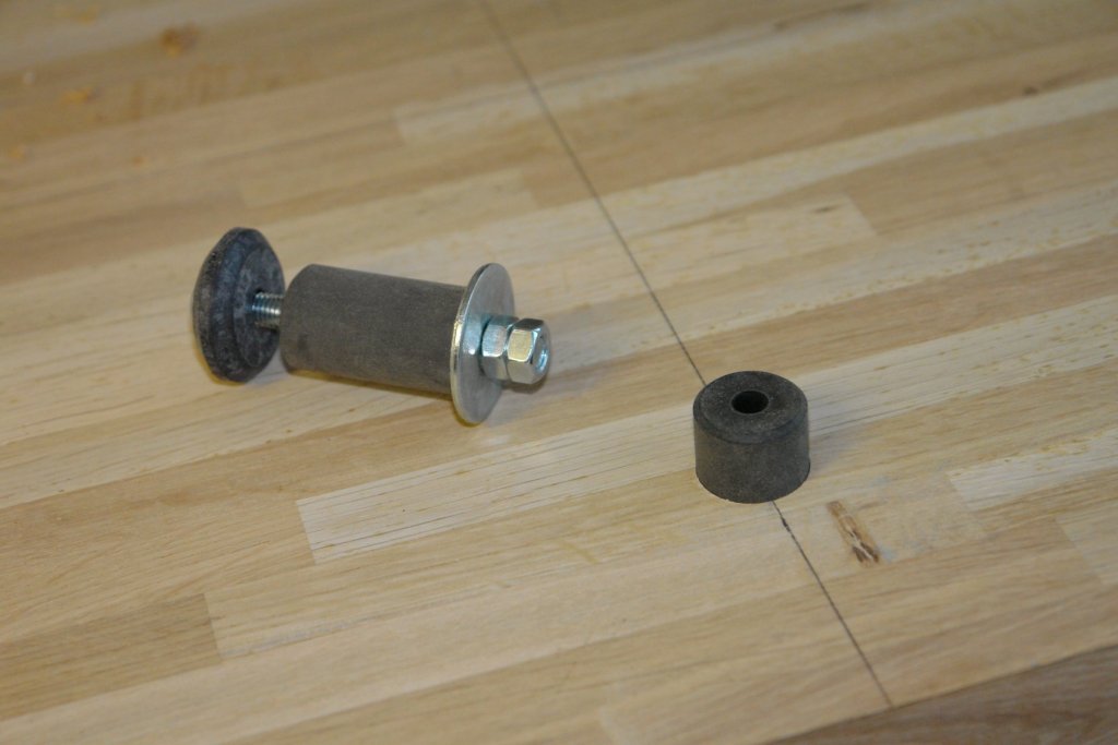
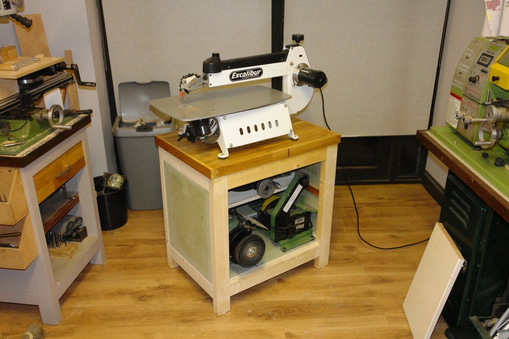
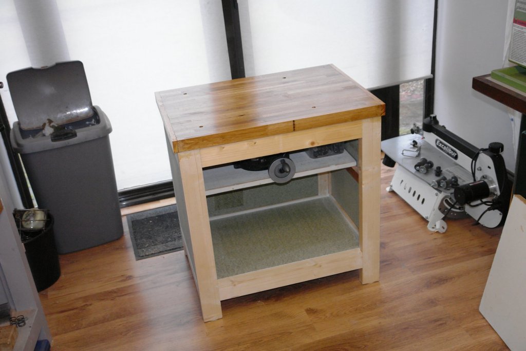
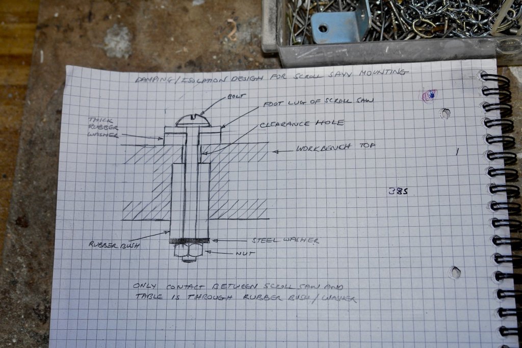
A few months ago I bought a second hand scroll saw, predominantly to make the cutting of frames easier and more accurate. Since then it has sat on the floor of the workshop gathering dust. Making the launch frames was the first opportunity to use it and practice. What I needed was a solid table to mount it on - hence the wood in the previous post. It would have been easier to have cut the frames with a piercing saw but that would have made the purchase of the scroll saw even more extravagant. Anyway to the bench - which I wanted to be of high mass and stiffness with good vibration absorption properties. I didn't want it bolted down to keep flexibility of space in the workshop. The frame was made from 3" x 1.5" pine with a very solid top made from a piece of 1.625" thick oak. To add stiffness and mass 3 sides and the base had inserted panels made from 0.9" flooring quality chipboard. I had a few rubber bushes from washing machine delivery packaging that I decided to use to isolate and damp the saw mounting lugs. The bushing was arranged to ensure that the only connection between the saw and the bench was through the rubber. The table top was drilled to take the bushes together with a clearance hole for the bolt. I built storage into the bench to take heavy items, increasing the mass further. So now I have the scroll saw ready to start making the launch.


-
A merry Christmas to you and yours Jon. I do get your reasoning on the future of this build. I keep thinking I need to get on to quite a few outstanding projects and that Altair is getting in the way. However I'm still thinking that the best way forward is to finish it, time will tell if I continue with this view.
-
Nils, its quite an attractive feature, its just a bit interesting that the original builders didn't just extend the hull length to give greater capacity and speed. I guess we may never know their thinking.
- 692 replies
-
- 4
-
-
- eagle of algier
- chebec
- (and 2 more)
-
Nils m- was there a specific reason for the overhanging deck / gratings at the stern? By the way the grating looks very neat.
- 692 replies
-
- 5
-
-
- eagle of algier
- chebec
- (and 2 more)
-
ancre La Salamandre by tadheus - 1:24
KeithAug replied to tadheus's topic in - Build logs for subjects built 1751 - 1800
Very interesting Pawel. What metal are you using?