KeithAug
-
Posts
3,986 -
Joined
-
Last visited
Content Type
Profiles
Forums
Gallery
Events
Everything posted by KeithAug
-
 Hello Bedford Thank you for the comments on the planking. Its nice to get positive feedback from someone who knows a thing or two about planking. Keith
 -
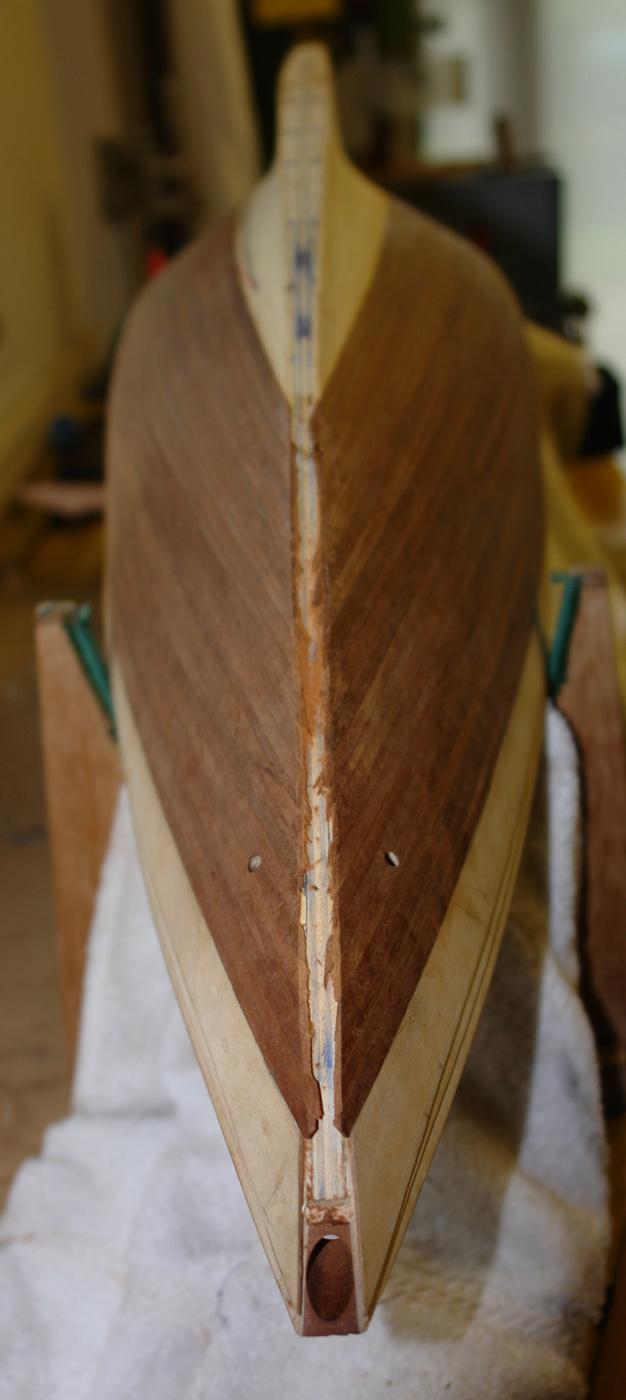
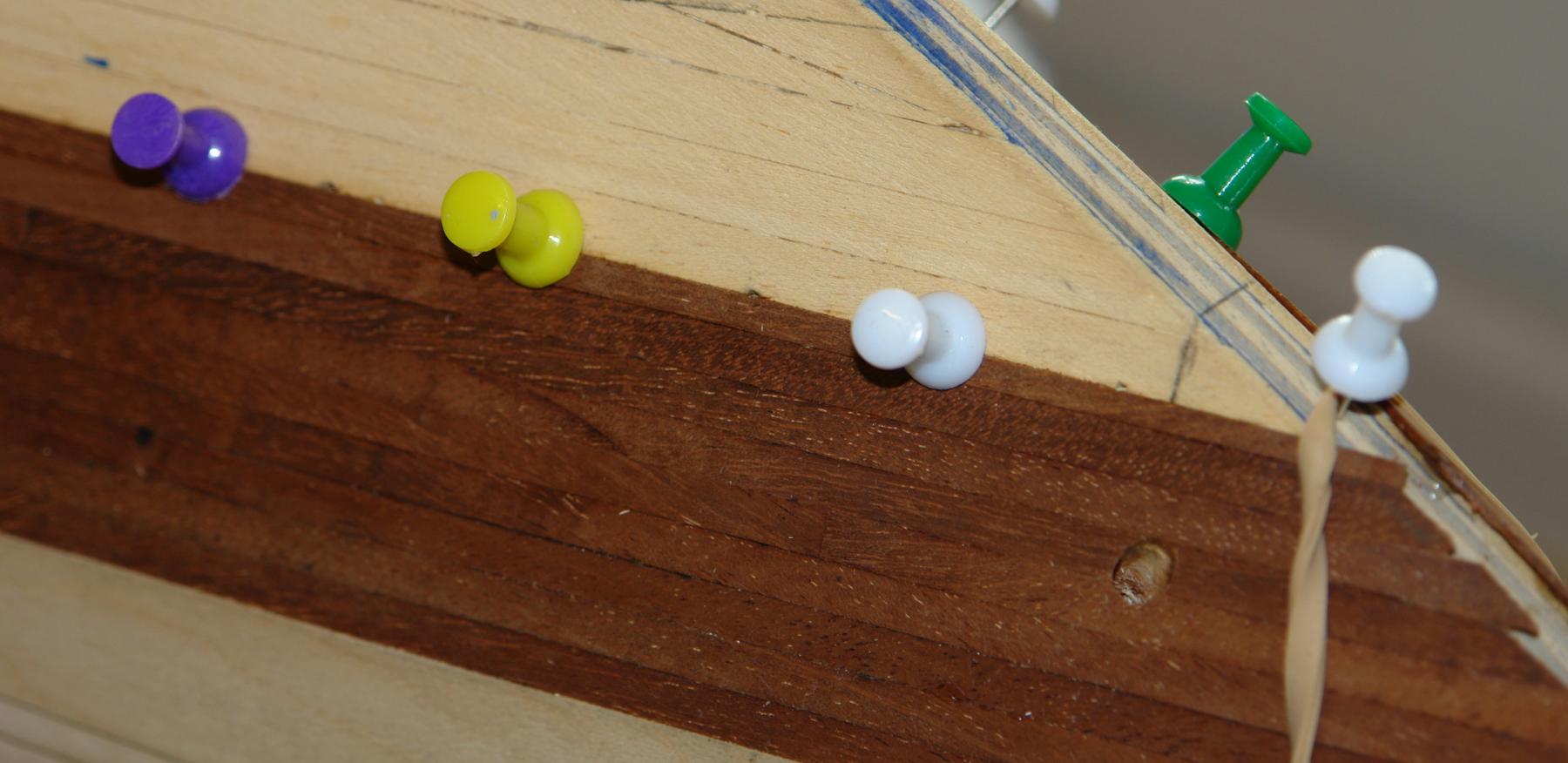
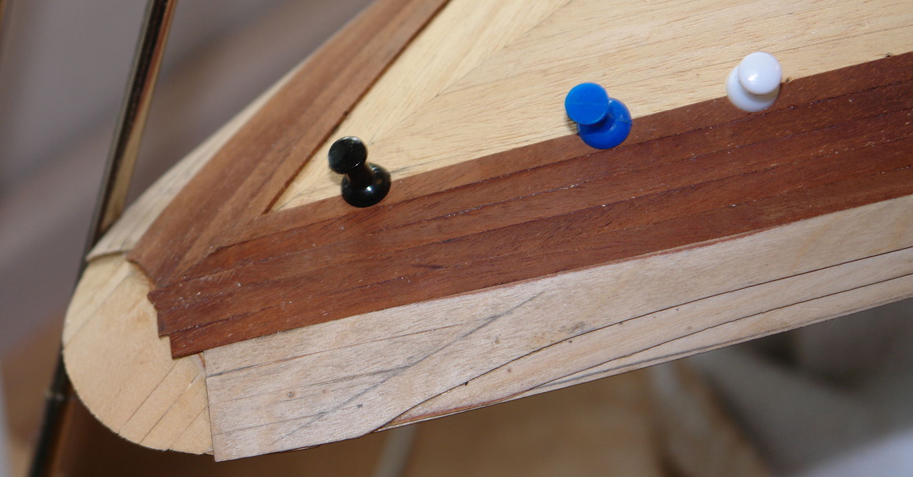
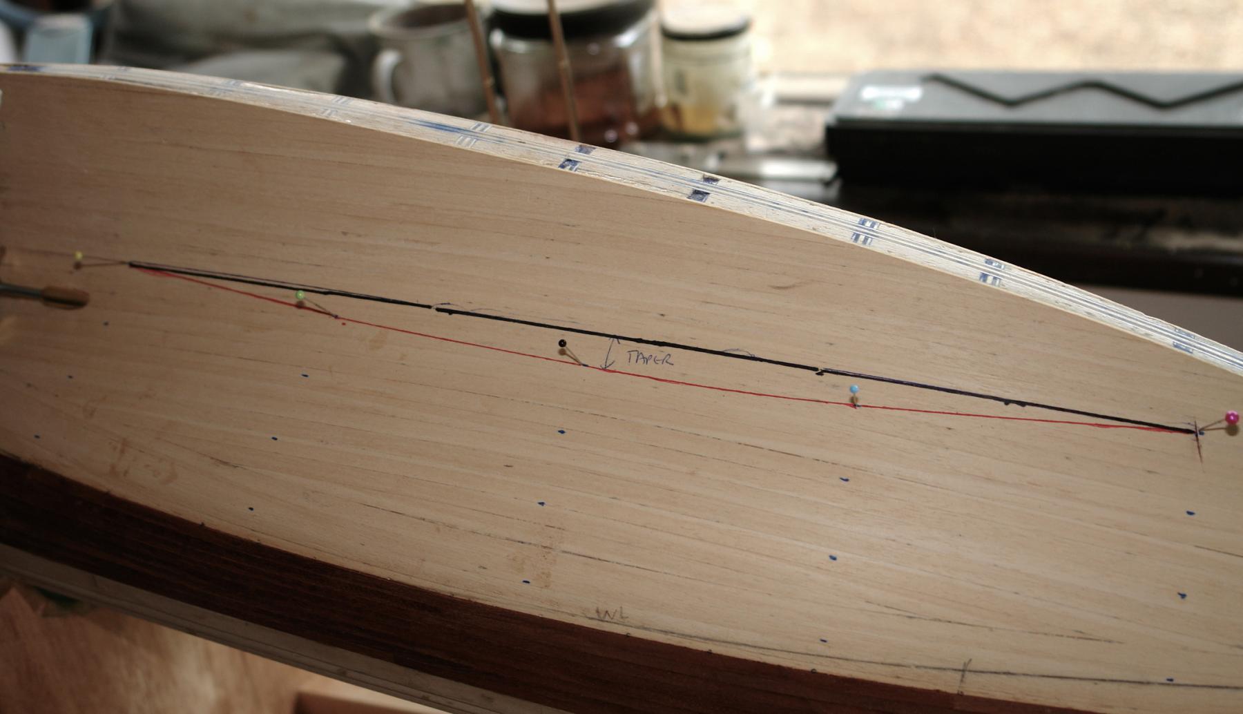
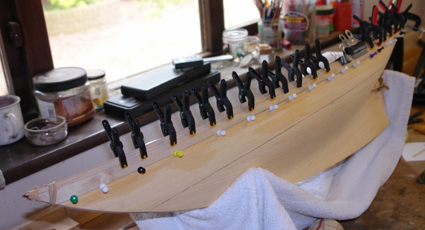
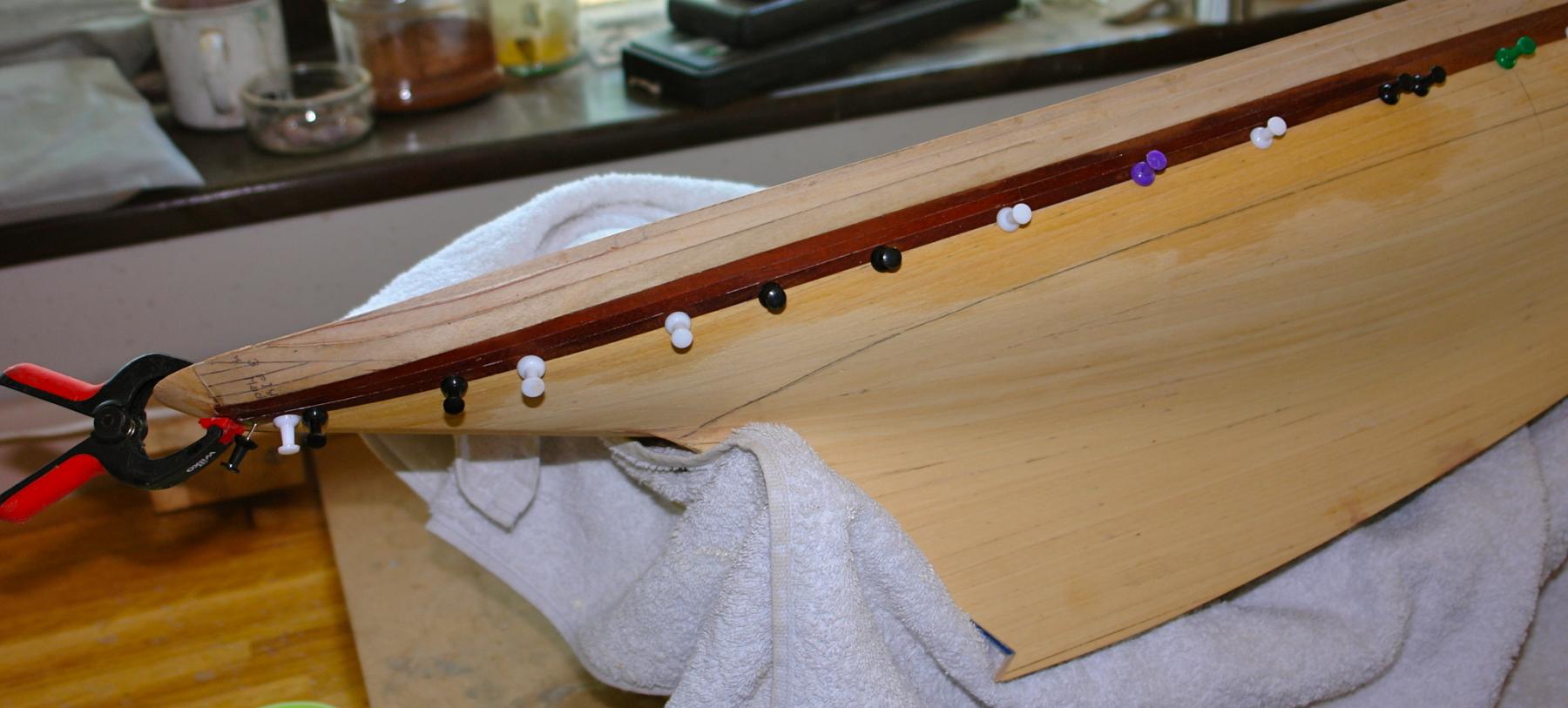
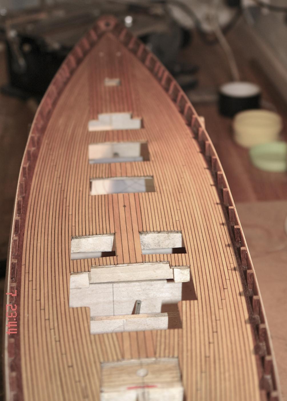
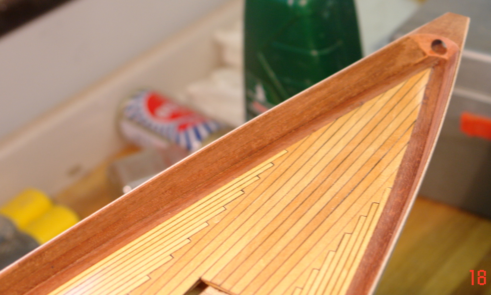
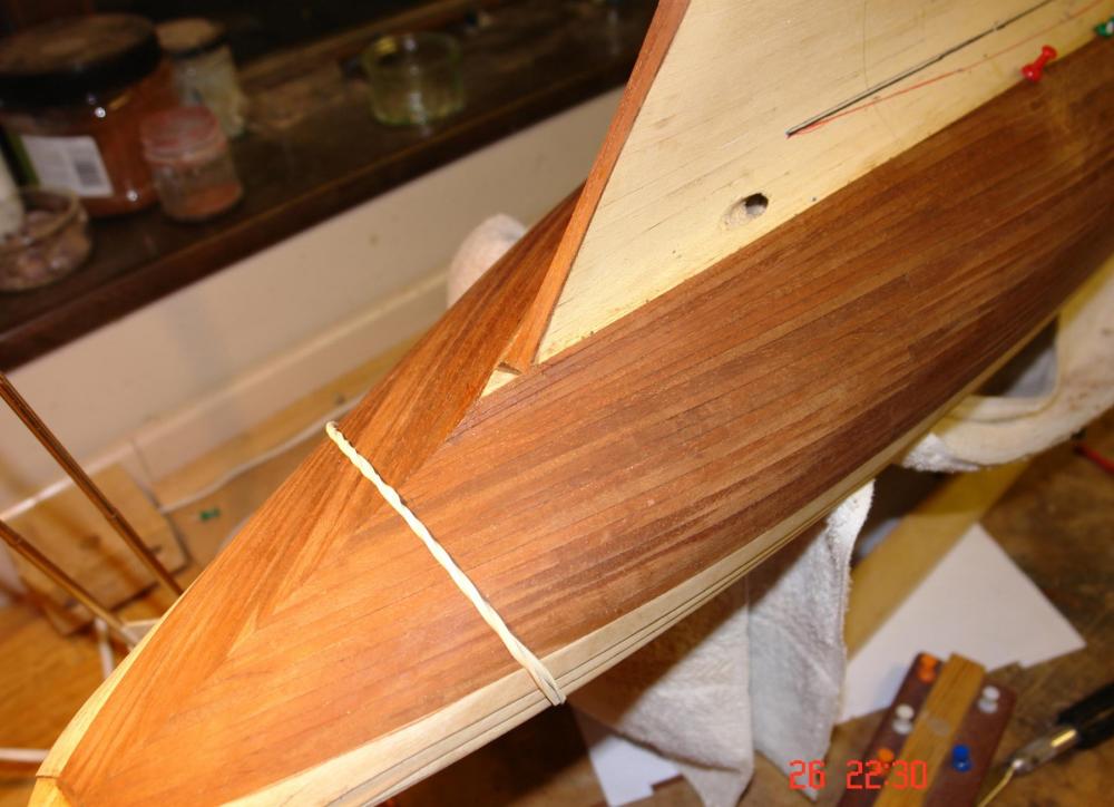
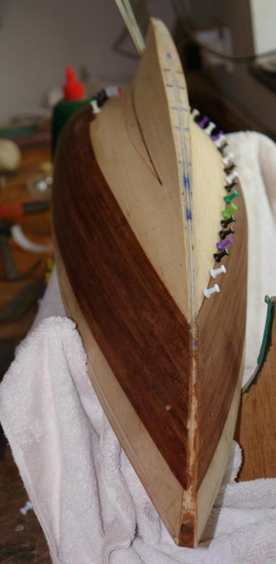
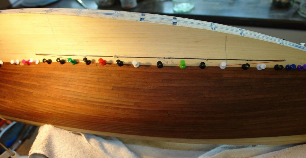
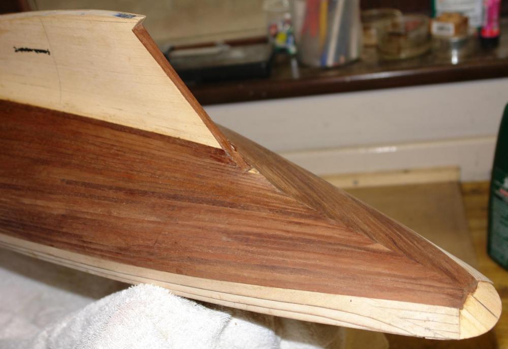
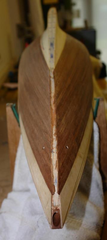
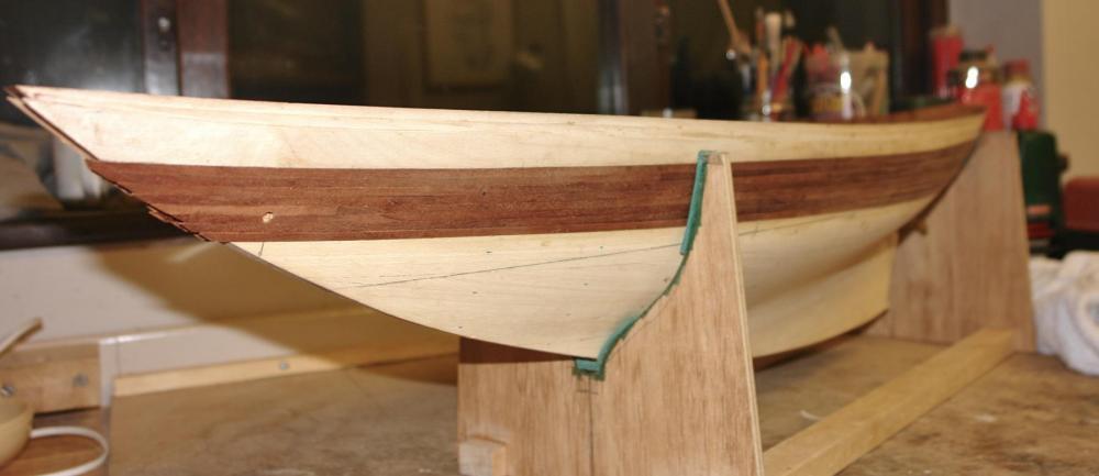
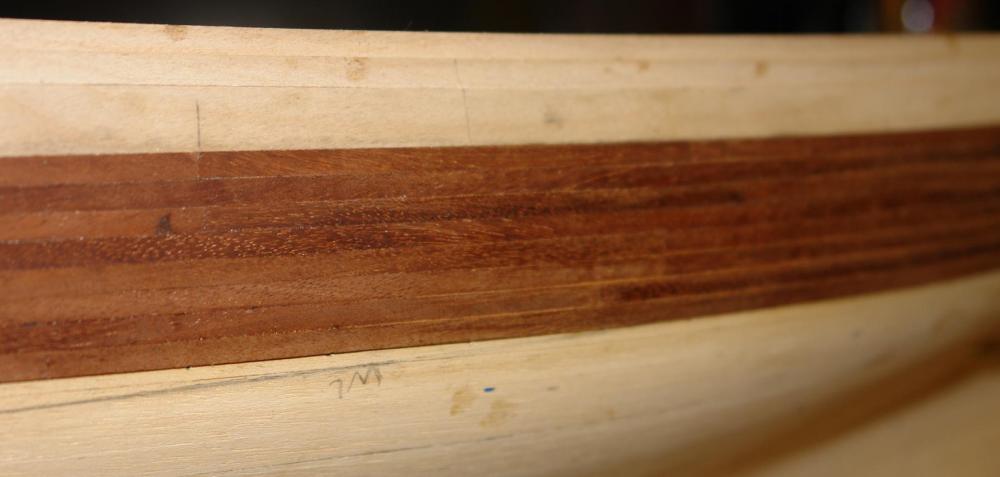
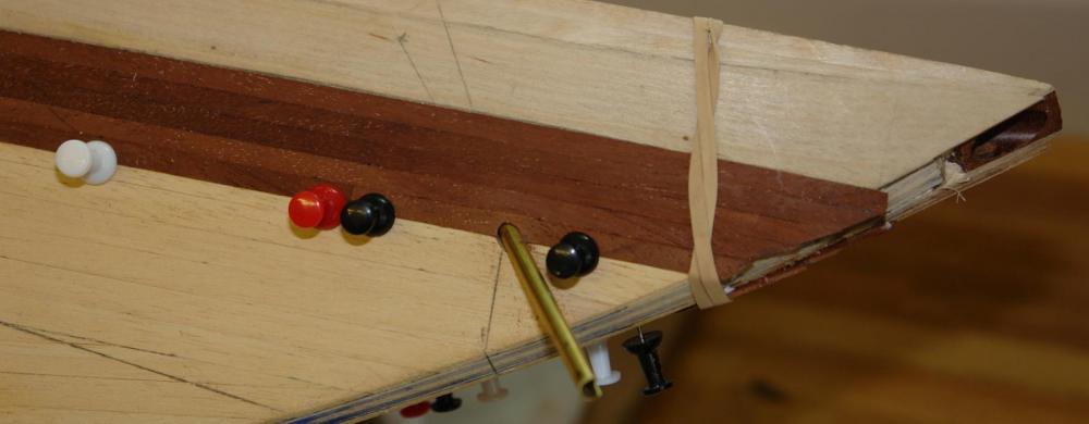
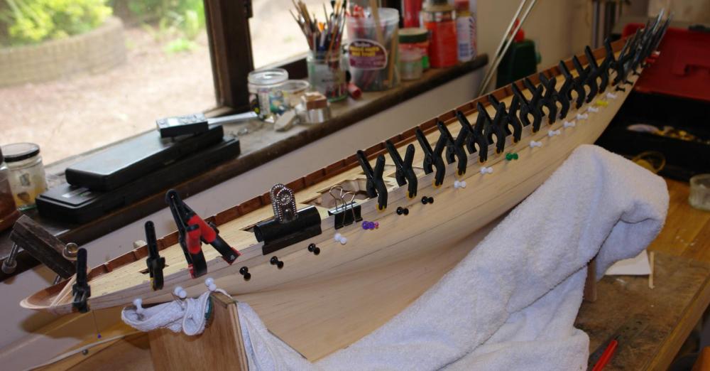
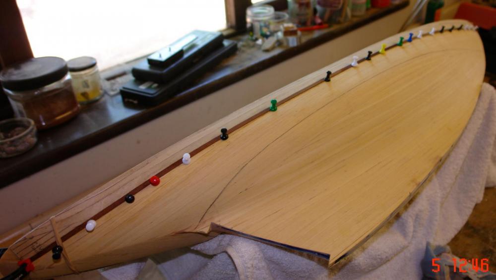
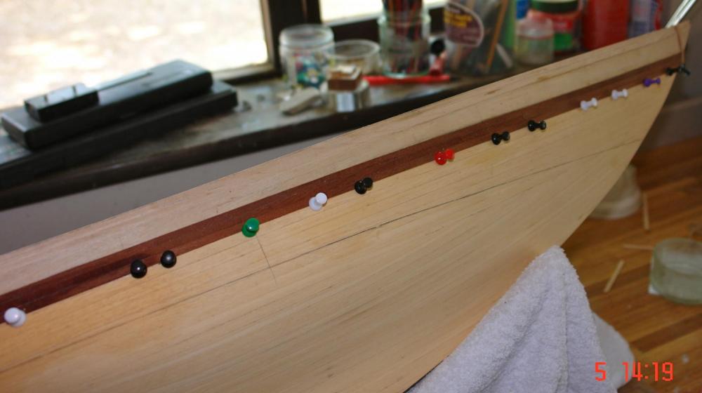
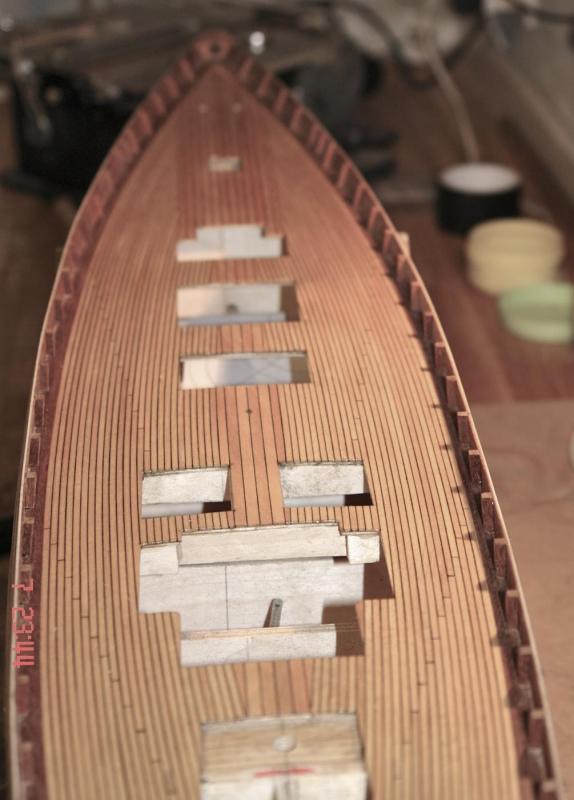
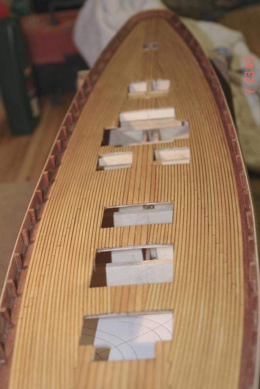
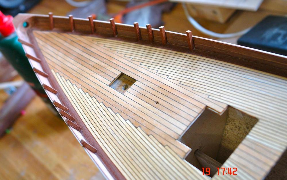
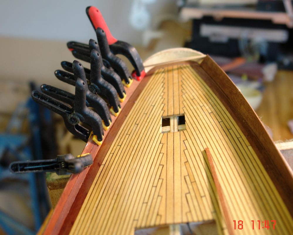
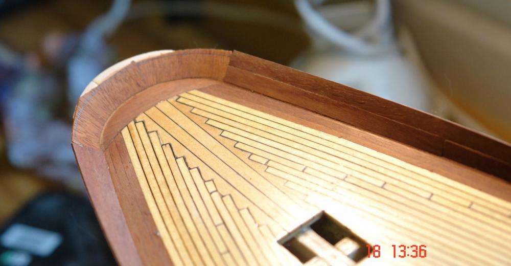
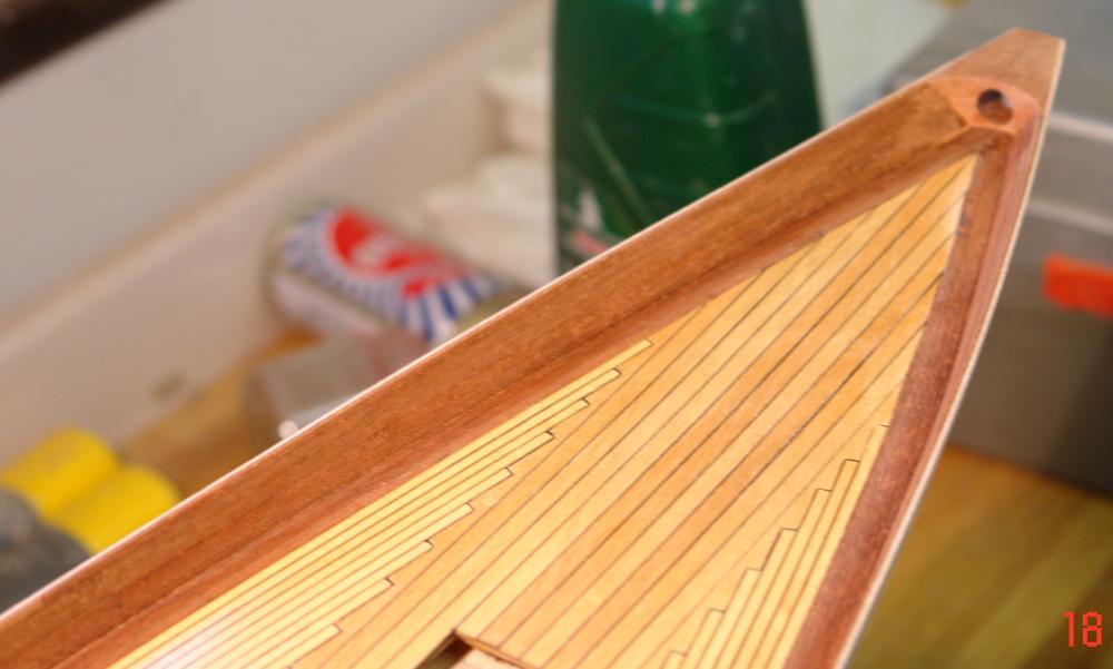
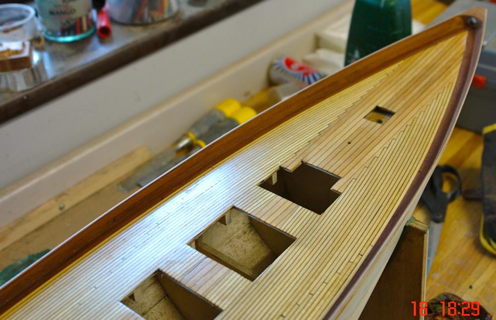
Appart from doing other stuff I have found a bit of time to progress the planking. On my last post I had started attaching the taper planks. I progressed the taper planks which started having the desired effect of filling the area of maximum beam while limiting the degree of bending in the stiff direction of the plank. I also planked the end of the keel in front of the rudder position. You may remember form a previous post I had marked the hull and identified where i would get to if I had pressed on with parallel planking (red line). Also you may recall that i wanted to end up at the black line. The plan worked reasonably well as illustrated by the photographs. I did have to do a fairly complicated adjustment by letting in a fillet pieces at one position on each side. See 4th plank down on the next photo. Much of the tricky planking is now done and most of the remaining planks will parallel, supplemented by finely tapered wedges to fill out the rear of keel.

- 882 replies
-
- 11
-

-
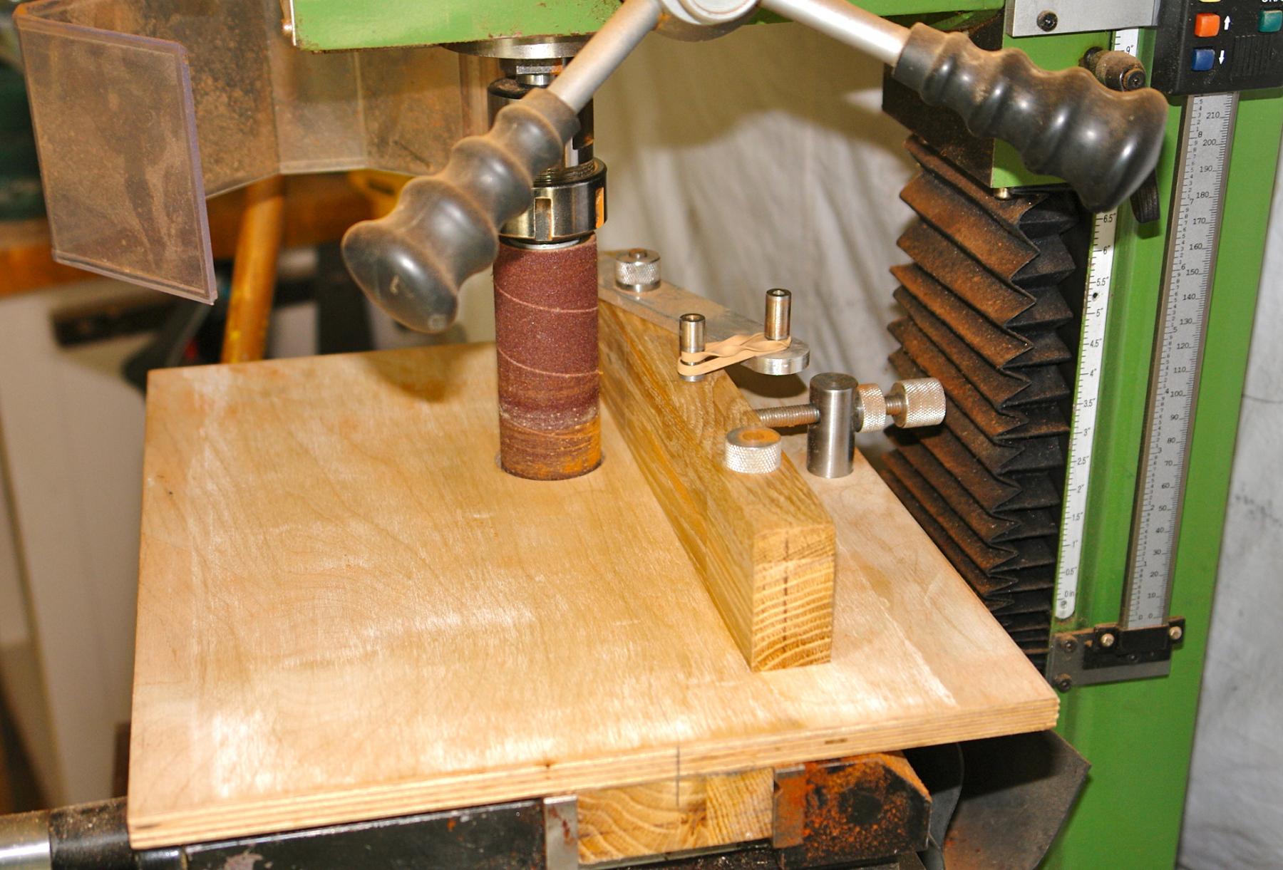
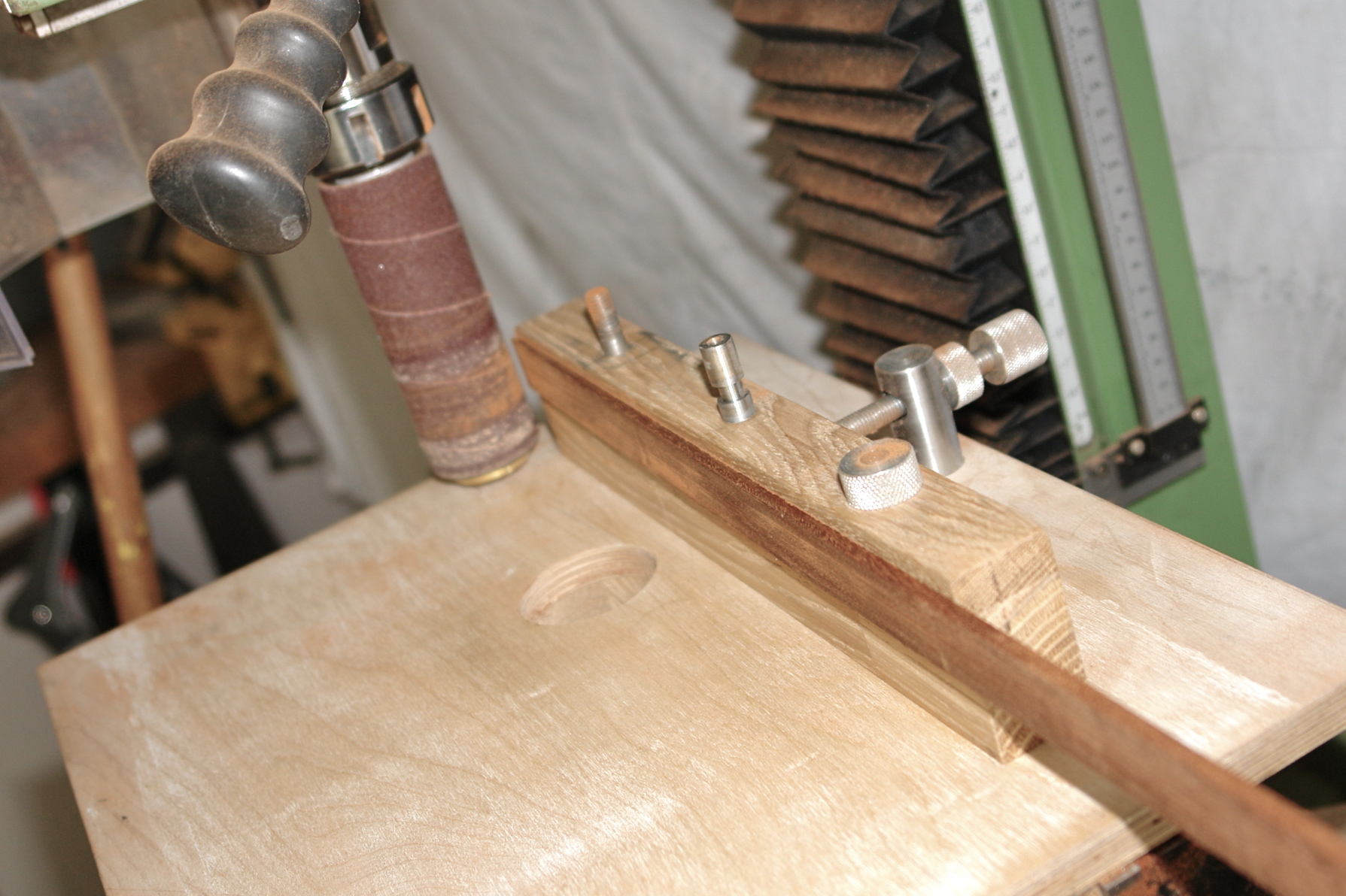
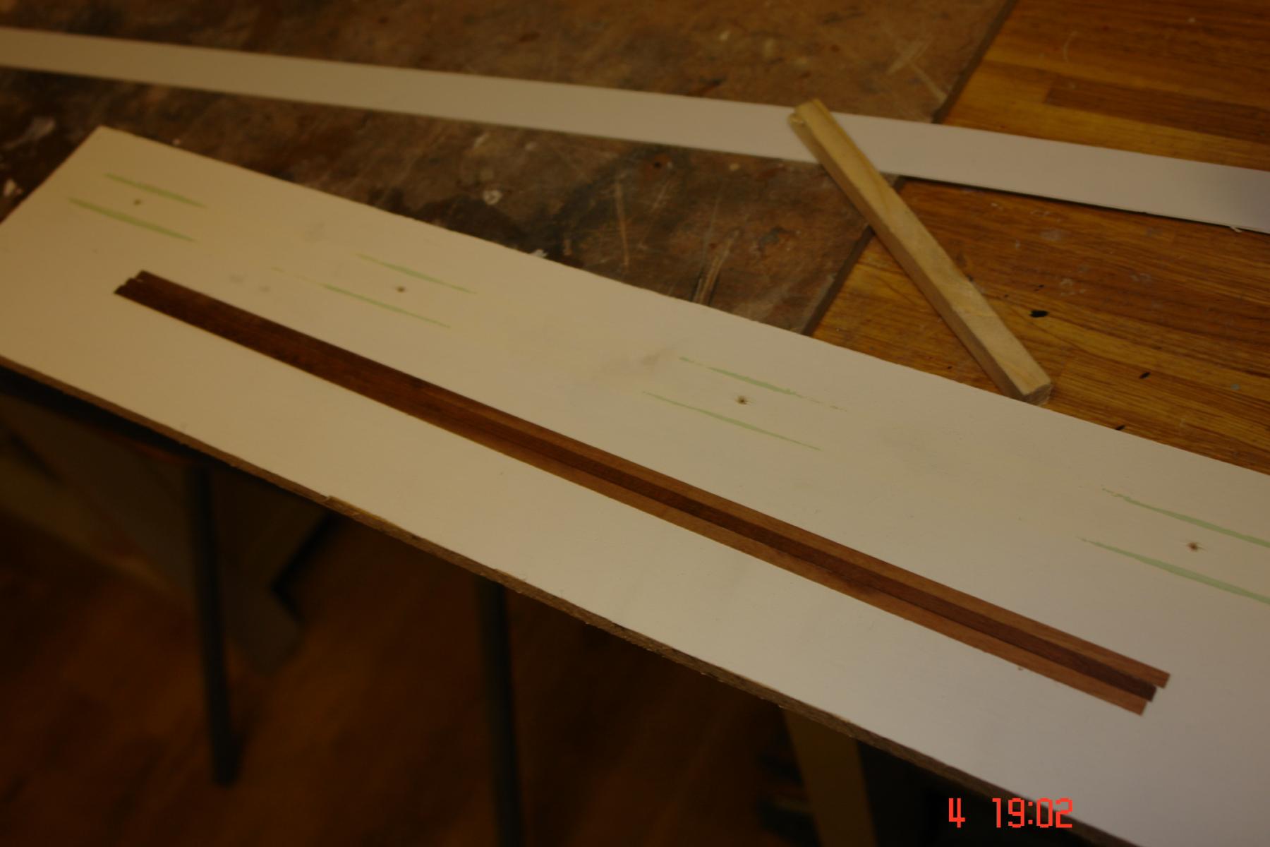
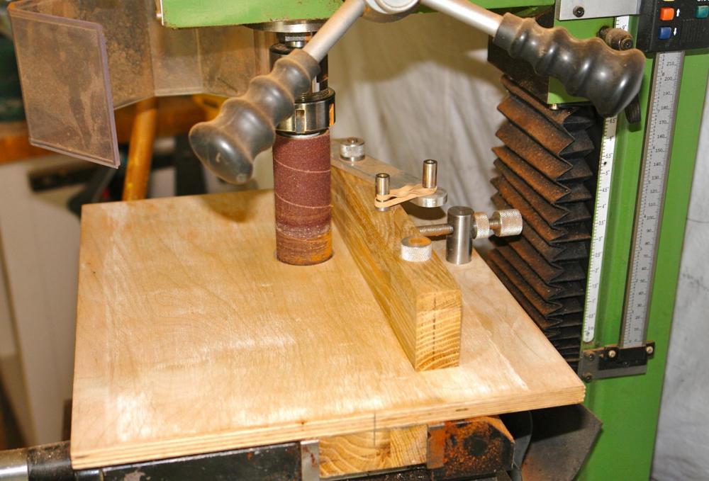
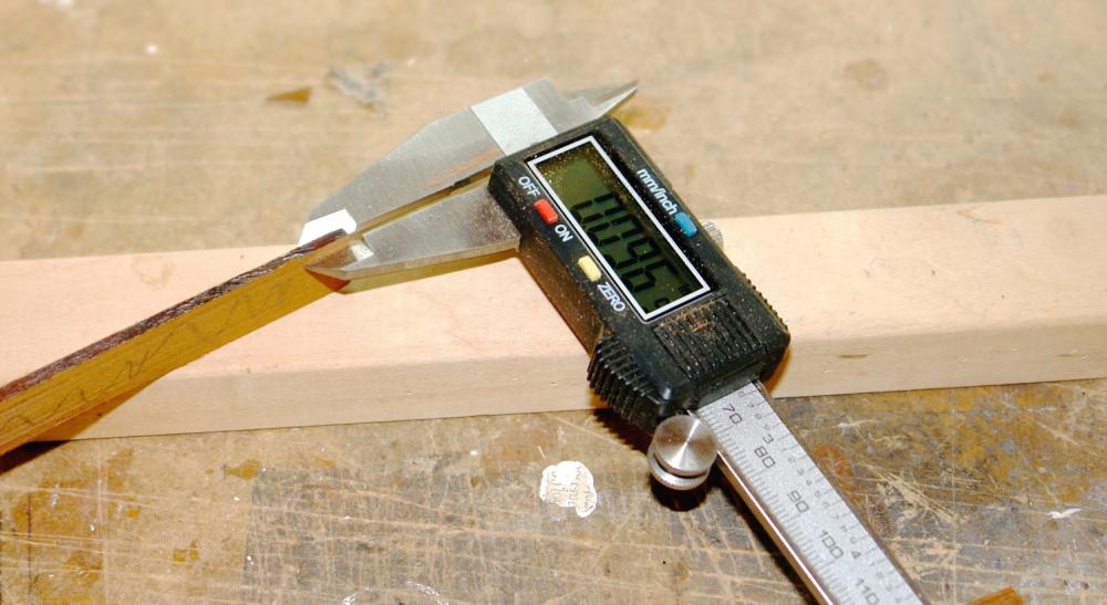
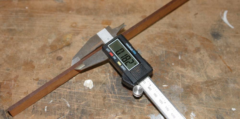
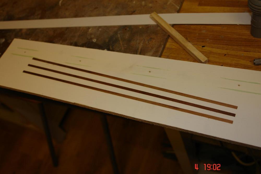
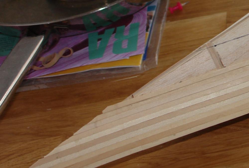
So here is my solution to creating uniform shallow taper planks. I have a home made thickness sander attachment for my milling machine as follows:- The oak plank up-stand is pivoted about the end towards the front of the photo with coarse adjustment being achieved by the screw adjuster to the right of the oak plank. Fine adjustment down to thousands of an inch is achieved by using the mill table adjustment. It all works very well for sanding parallel planks. I realised I could use the thickness sander to taper sand by setting the oak plank at the desired angle and sticking the workpiece to the the oak plank using double sided tape. Then by traversing the workpiece past the sanding drum (using the mill table) I was able taper sand the workpiece. I should explain that the final planks were going to be slit from the tapered workpiece using the table saw. I wanted a taper of about 1/3 of a degree over the 15 inch length of the workpiece - which equates to the narrow end being about 1/2 the thickness of the wide end. This photo shows the tapered workpiece laid alongside a parallel workpiece. And the dimensions achieved. The final photos show the tapered planks being attached to the hull.


-
For interest - here is what the real thing looks like. Hopefully the model will do the original justice.
-
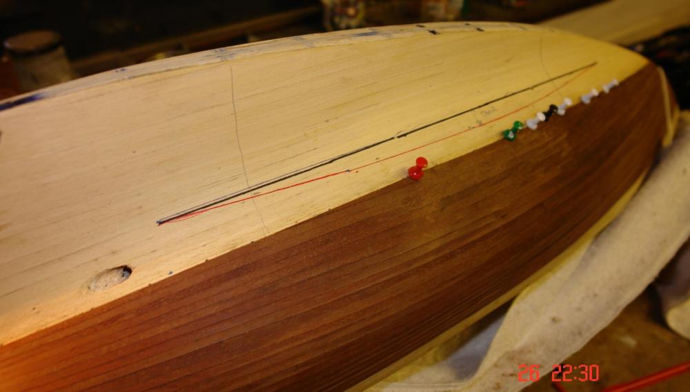
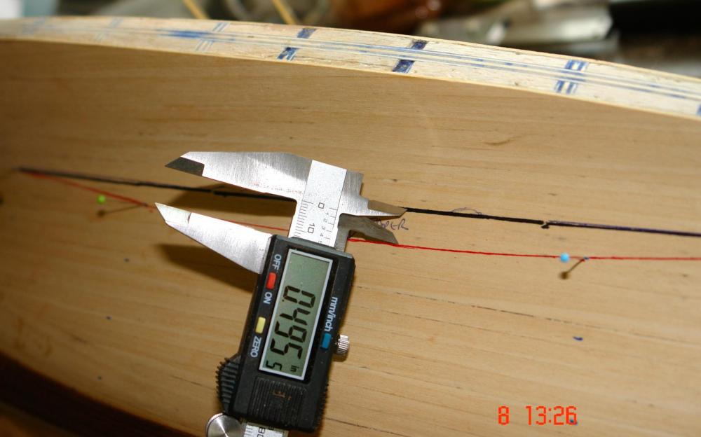
Thank you Mark and John for your supportive comments. I have been progressed a little with the hull 2nd planking. I find it is quite easy to over think the planking and I prefer to just get on with it and let the planks tell me when they are finding it difficult to follow one another. In this case this started to occur after the 8th / 9th parallel plank. At this stage I marked off the hull as though I would continue with parallel planks. This produced the red line on the photo. I concluded that planking to the red line (even if it was possible) would produce a quite unrealistic planking effect on the keel so I drew the black line to represent where I wanted the planks to fall. Measuring the space between the lines gave me an indication of how much "extra" planking width I would have to find at the waist - .495 inch (about 3 plank widths) in this case. I now need a cunning plan for manufacturing a reasonable number of accurately formed taper planks. I feel a bit of experimenting coming on.


-
Hello Kees she is not not the sleekest of yachts (a bit on the beamy side). But never the less she has curves in all the right places.
-
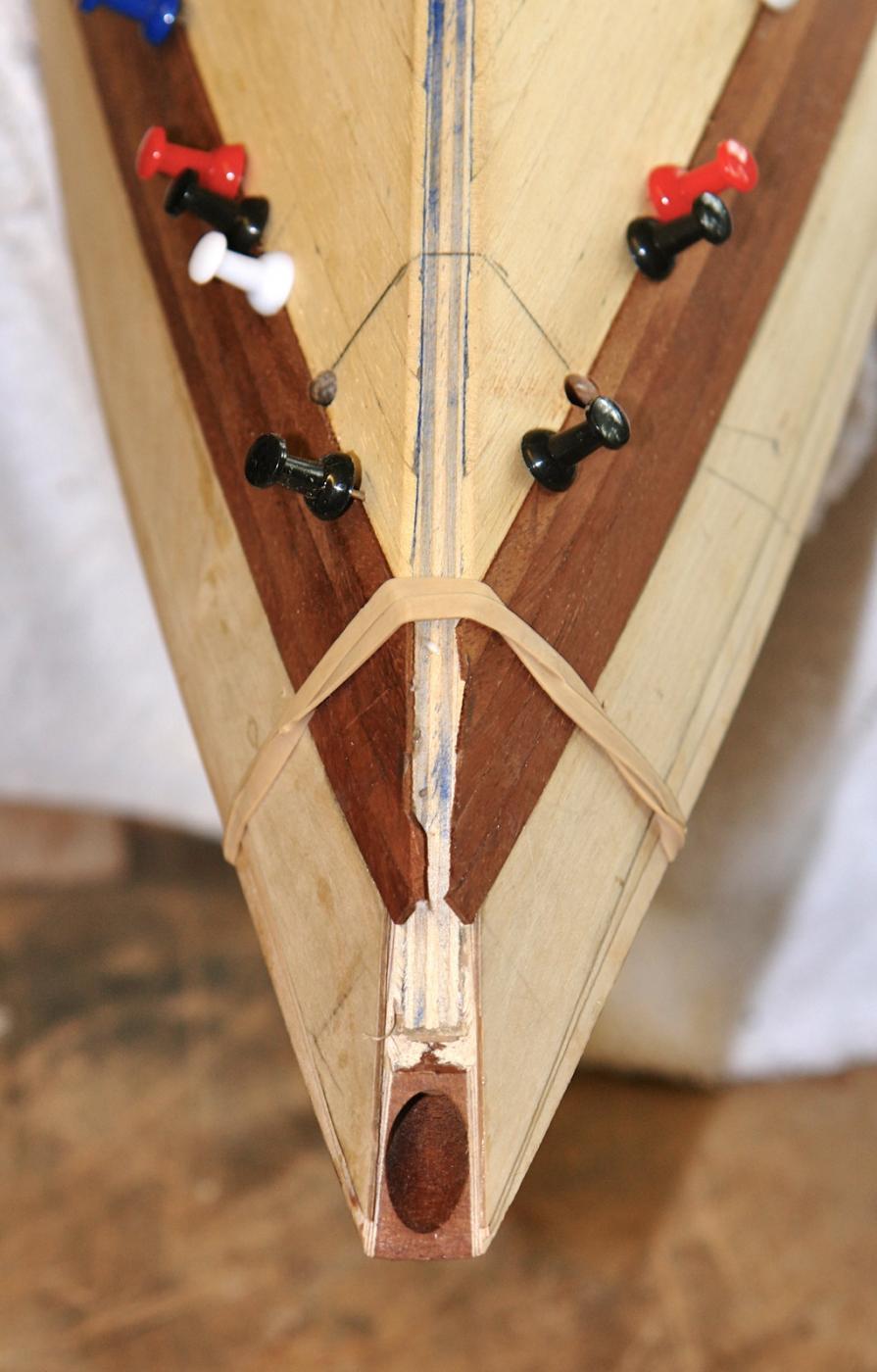
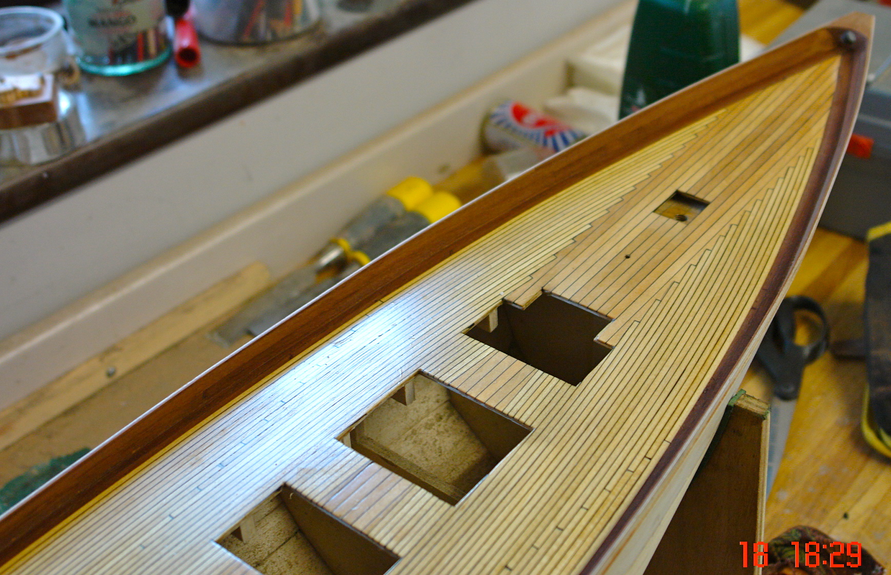
Before getting too far into the 2nd planking I needed to drill the holes to take the hawse pipes (one on either side of the bow). These are at a compound angle flaring outward and forward as they descend through hull. Three options were available for drilling as follows:- 1, Drill from the deck and exit the drill through the hull. 2, Drill from the hull and exit the drill through the deck. 3, Drill half way from the deck and half way from the hull - meeting in the middle!!!!! Option 3 would appear to be bonkers however............ Options 1 and 2 have the potential for the exit holes to be out of position - which I thought would look awful. So option 3 it was! I marked guide lines on the hull at the correct angle and used my hand held drill carefully judging the correct angle. By using a smaller drill than the final hole size and enlarging it with a circular needle file I did manage to make the holes join up. I finished with a 0.16" (4mm reamer to clean up the holes so the hawse pipe would fit snugly.


-
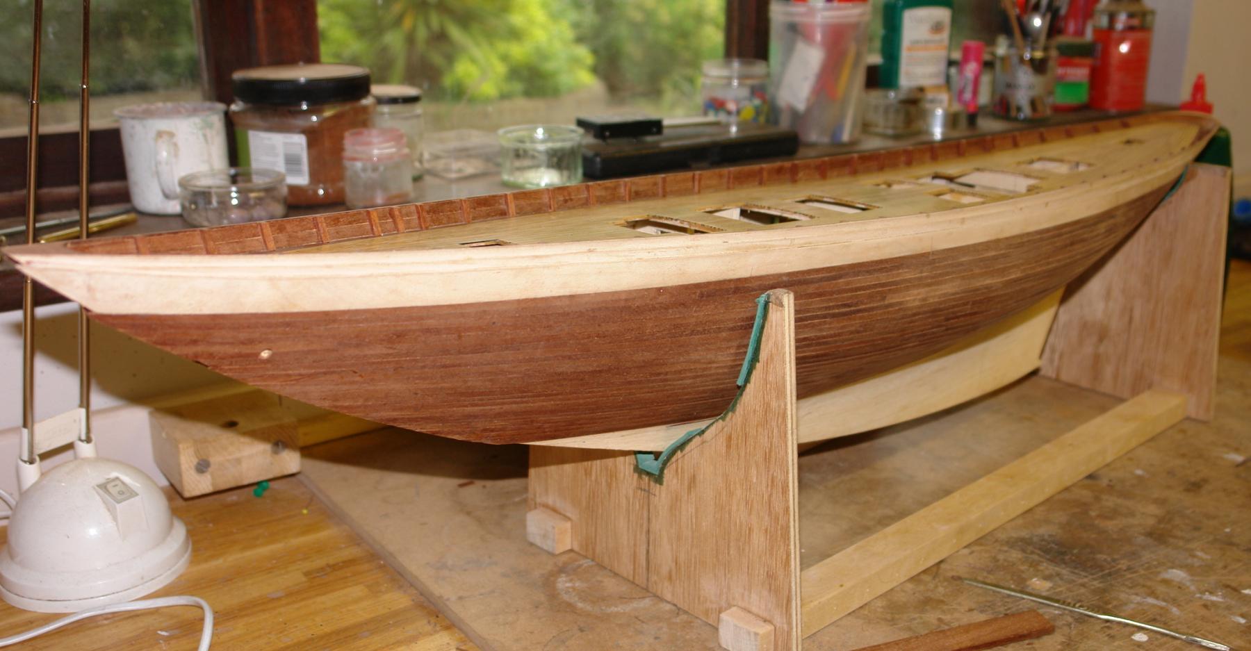
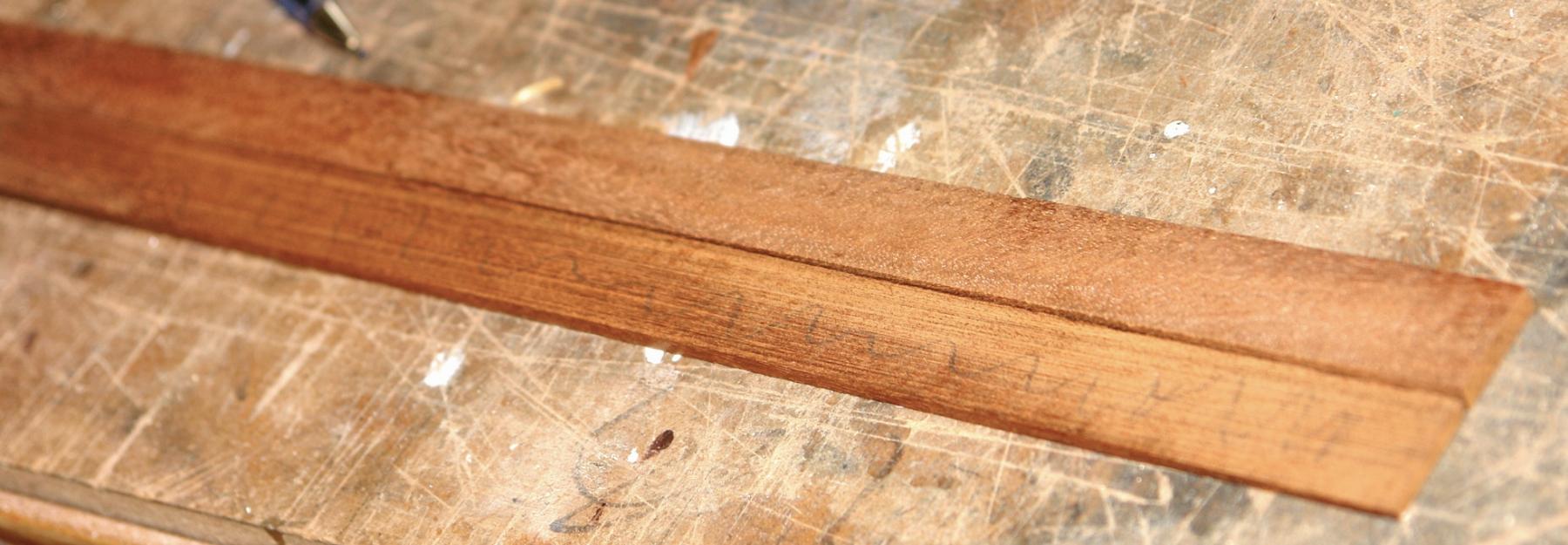
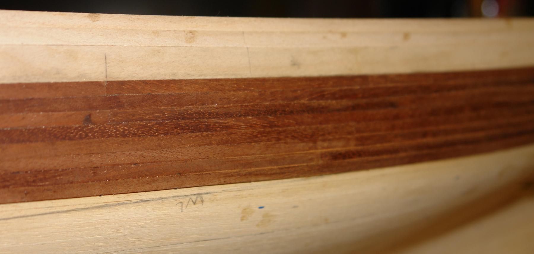
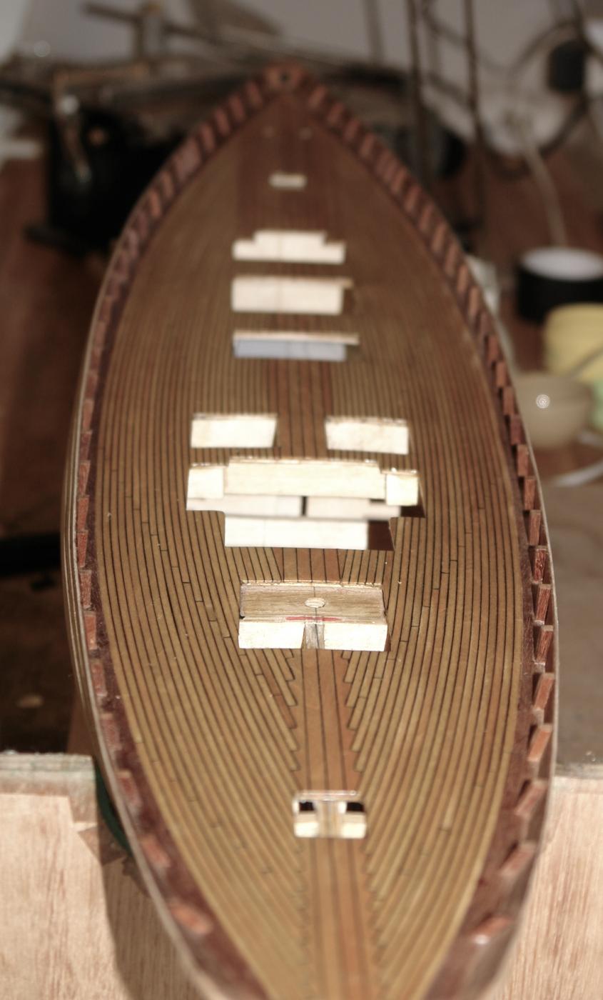
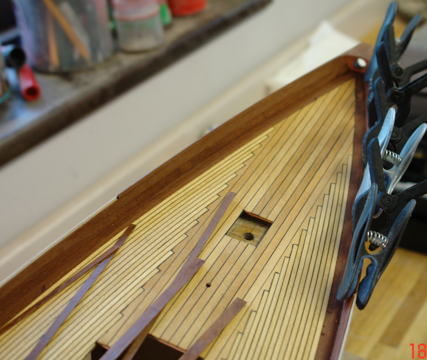
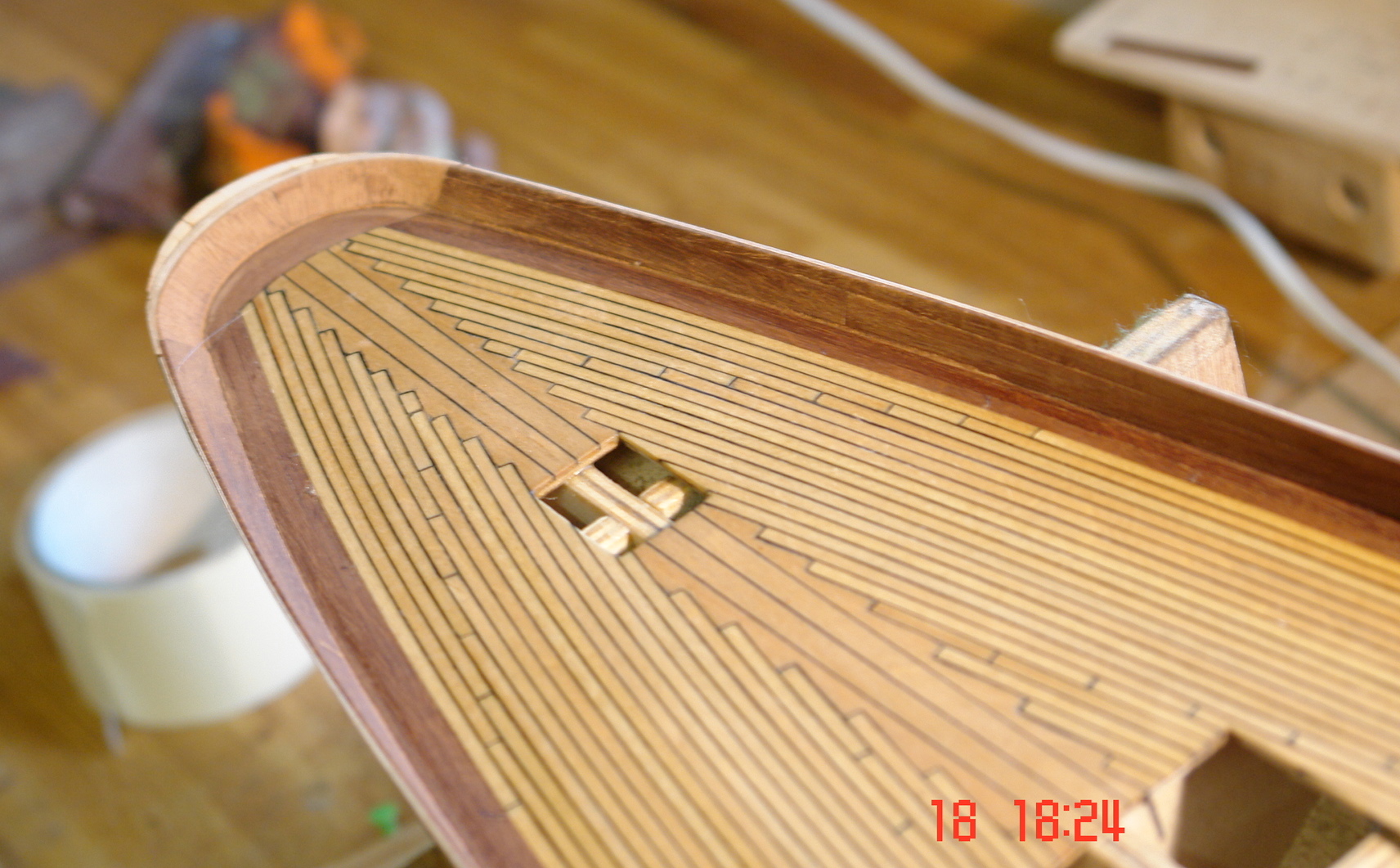
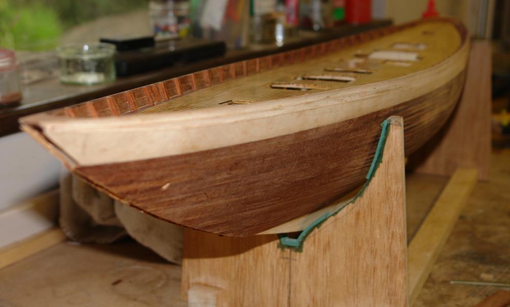
Having completed the ribs I decided to attach the 3rd of the profiled 1/32 inch (actually .036') plywood layers that went to create the profile at the upper edge of the hull. With this in place it was time to commence the second mahogany planking. This was cut from the old table top mentioned earlier. The planks were .036" x .180" x 15 inch. The first plank went on butting up to the step created by the 3rd plywood layer. the bulwarks have turned out well and are very solid - testament to the strength of layers of laminated plywood. 3 layers of planking now in place. so far, so good. I should probably explain at this stage that the plywood will be painted white while and I am considering leaving the mahogany visible - probably satin poly.


-
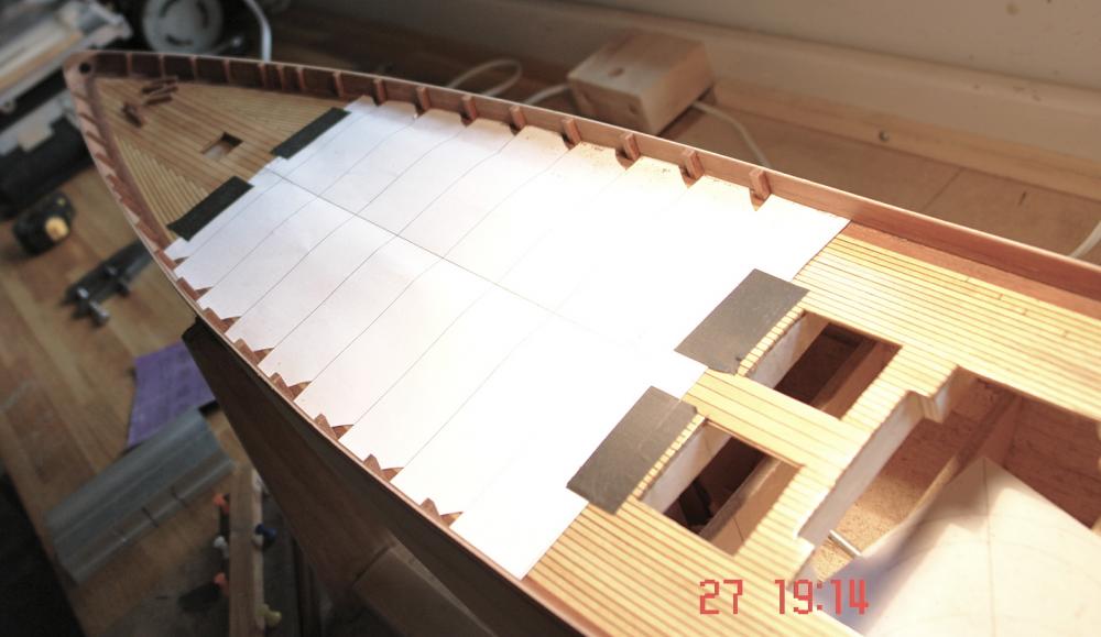
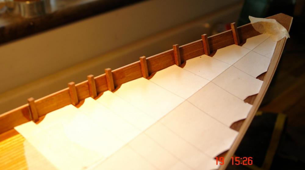
I managed to get enough time to complete the ribs. I was struggling a bit to see the laser line until I realised the batteries were about 10 years old. the new ones improved matters greatly......... With all the ribs attached I used a flexible dowel (zero kerf) pull saw to trim them back to the height of the bulwark.

- 882 replies
-
- 11
-
-
Michael Sorry my reply wasn't easy for you to understand. This is the type of blade I use. Sold by www.rdgtools.co.uk. It is a bit too big for your table saw. 4" HSS SLITTING SAW 0.8mm WIDE / 1" BORE MAXIMUM UP TO 130 TEETH FOR BETTER CUTTING SEE OUR OTHER SLITTING SAWS IN OUR EBAY SHOP Be sure to add me to your favourites list!
-
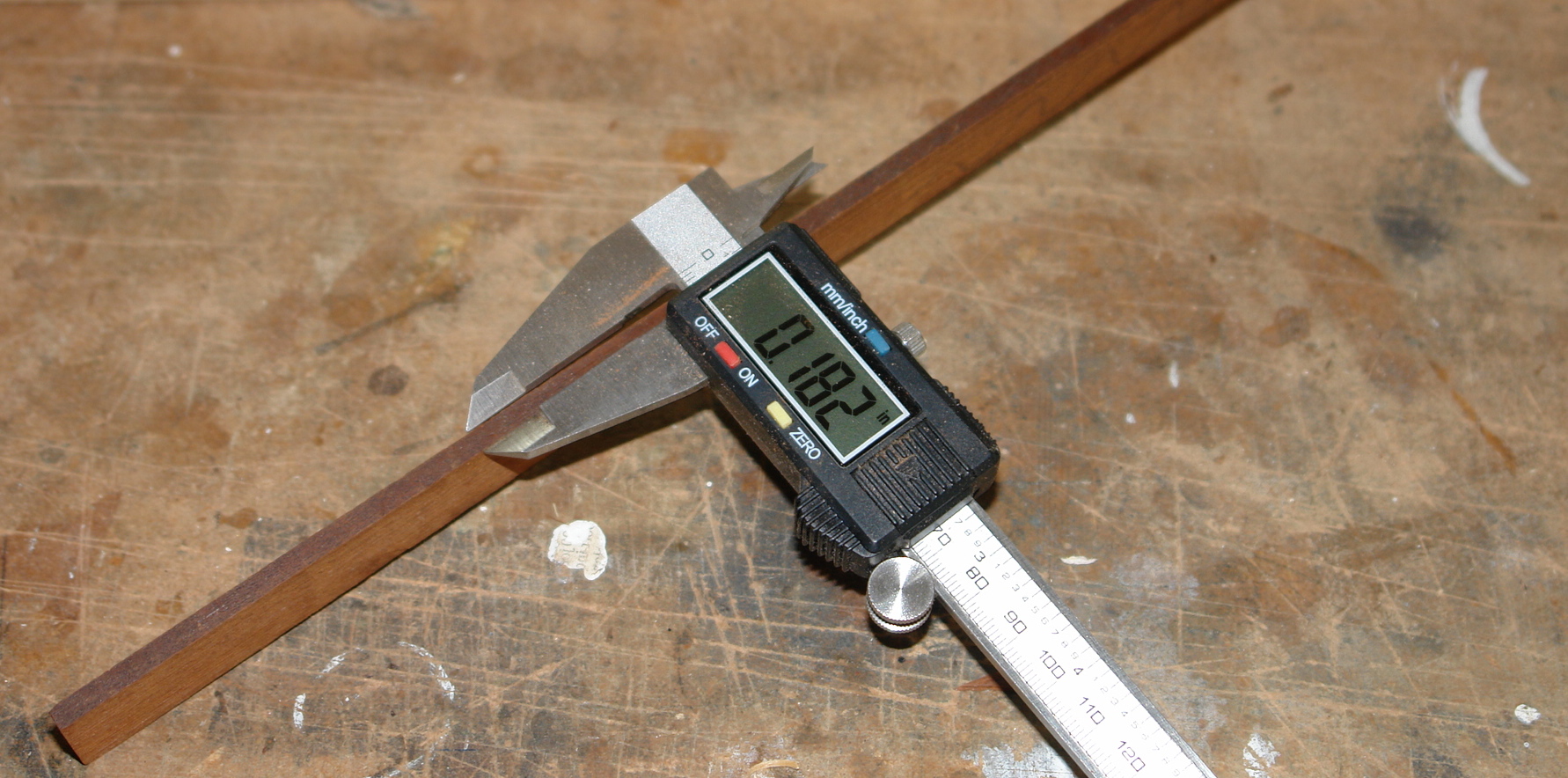
Michael - sorry should have said the planks are .031 inches thick and .200 inch wide.
-
Michael I use a metal cutting slitting saw blade which is 1/32 (.031) inch wide and has zero kerf. This gives me an almost polished finish to the planks and control on thickness of +/- .0015 inch. The blade has 108 teeth and was bought off the web for about £6 (probably originated from China). I don't have a Proxxon saw and I think the problem you are going to encounter is getting a slitting saw bade of 80mm X 10mm bore. I think this sizing is pretty much exclusive to Proxxon (unless someone else know different). Example of my planks cut with the blade described above :-

-
Hello Francis I have never found a way around the 2MB limit other than resizing the image in the camera or cropping the image on the computer. Keep me posted on your progress. Regards
-
Francis I should add that their is more than one way to skin a cat and your option of leaving the fore keel frames square and then adding triangular stock is equally valid. If you look at my Altair link below you will see that it adopts the alternative method you suggest. Regards
-
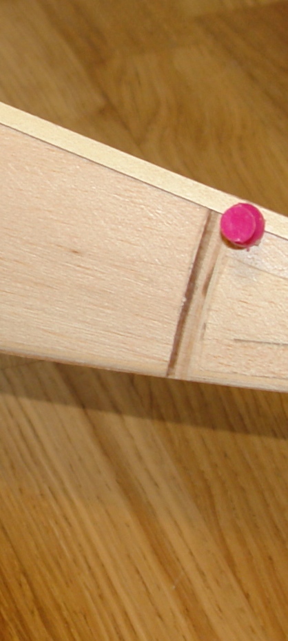
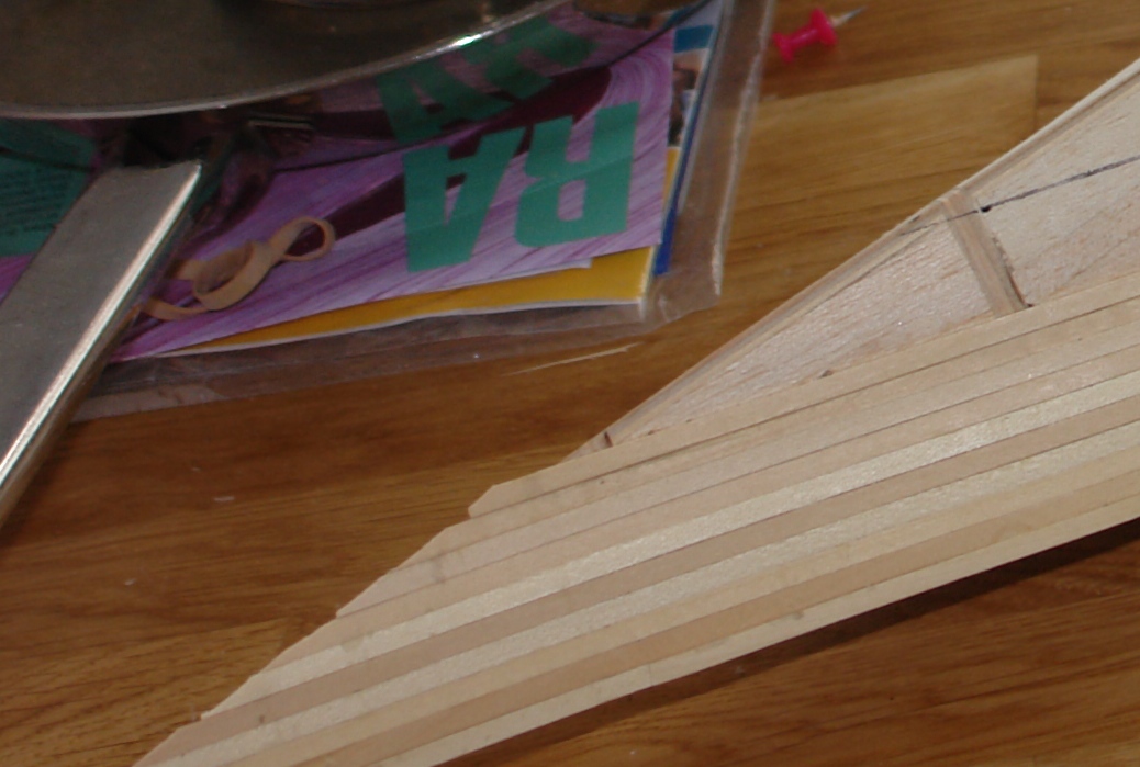
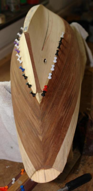
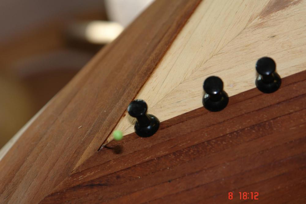
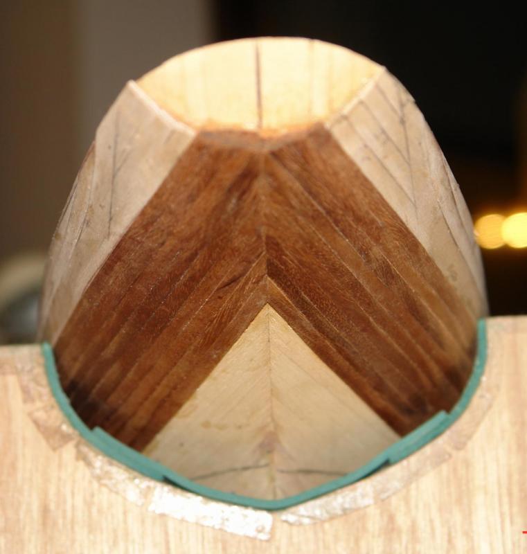
Hello Francis I am happy to help but I may need a bit more information to understand your questions. In terms of the balsa backing what I did was as follows:- I initially didn't remove the scorched edges of the frames because I wanted to use them as a guide when sanding. I then sanded the balsa back to the frames. On the fore and aft frames the sanding removes only some of the scorching. This because the curvature of the hull means that the frames themselves have to be flared. The trick is to leave a very thin line of scorching at the high edge of the frame. See Photo - At this point the sanding of the balsa is complete. On the middle frames (which have minimal flare) I sanded the backing until the scorching on the frames was lightly removed. I'm not quite following your point re the sharp V on the keel. The bulb of the keel is a round shape which transitions to a sharp V as you move forward. Anyway I didn't find the need to leave it square and then glue on triangular stock. I just shaded the longitudinal frames to form the sharp V. To get the planking sharp at the keel I laid the planks with circa 1/4 inch overhang. I then sanded them back from the opposite side of the hull. Making sure that the sanding block was always parallel with the opposite side of the hull, and taking care not to remove more of the already sanded balsa / frames on that side. I then did the opposite when I had planked the other side. The attached photo shows the frames sanded to a sharp v and the planks being attached with a overhang I hope that makes sense, but if not get back to me. I'm happy to answer any other questions. Are you planning to do a building log - it would help me to understand your questions better and perhaps give some pre warning of issues you might be about to encounter. Regards.
-
Proxxon Micromot DB 250 MICRO Woodturning Lathe
KeithAug replied to Holty's topic in Modeling tools and Workshop Equipment
Marc If you are still considering a small wood lathe you might want to look at the Axminster Tools site. They sell the proxxon but it gets mixed reviews. In particular at 150w its fairly low on power. The machine below is 350w and generally gets consistently better reviews for little more cash. -
Planking questions
KeithAug replied to tarmes's topic in Building, Framing, Planking and plating a ships hull and deck
Hello Tim J class hulls have finer lines and less pronounced changes in curvature than many boats. When I built my Amati Endeavour I found that it planked very well with parallel planks. The finish also looked good. Lots of planking detail in my build logs that may be of interest to you. Keith -
Proxxon Micromot DB 250 MICRO Woodturning Lathe
KeithAug replied to Holty's topic in Modeling tools and Workshop Equipment
Hi Holty As Richard explains (above) the easy way to turn long masts is to take the spindle out of the tail stock and use it as a steady (making sure to support the overhang to stop the mast whipping). I turned the 5 foot long mast for my Endeavour on a lathe having a 18 inch between centres. See Photo The bush in the tail stock isn't visible in the photo but the anti whipping support is (its on the right) You can see more details in my Endeavour build log.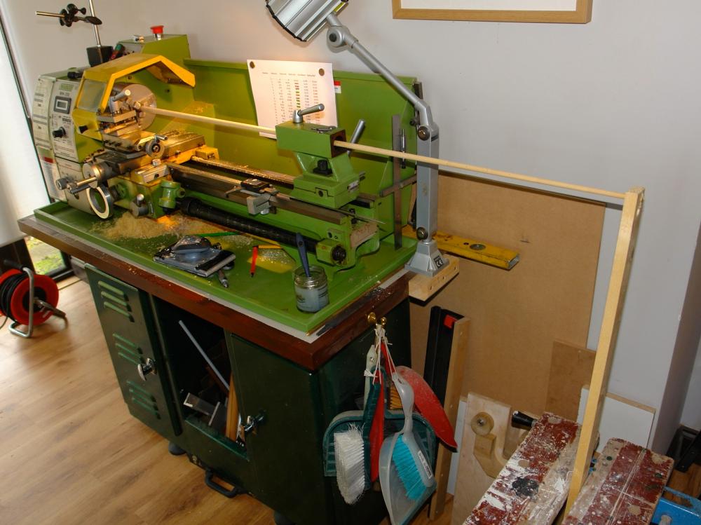
-
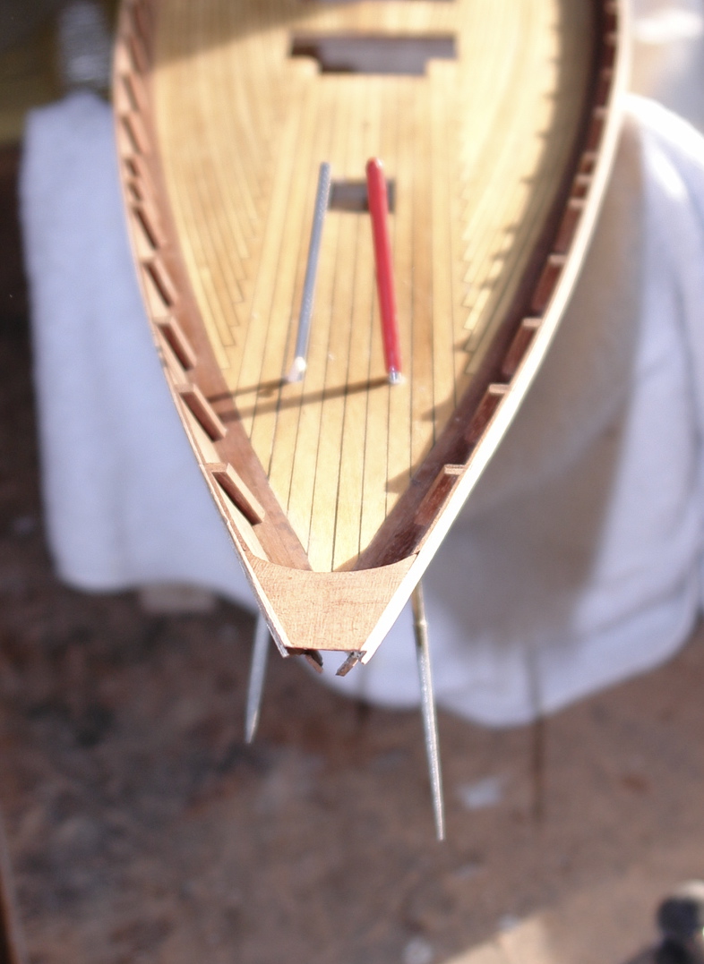
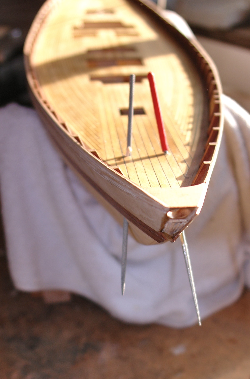
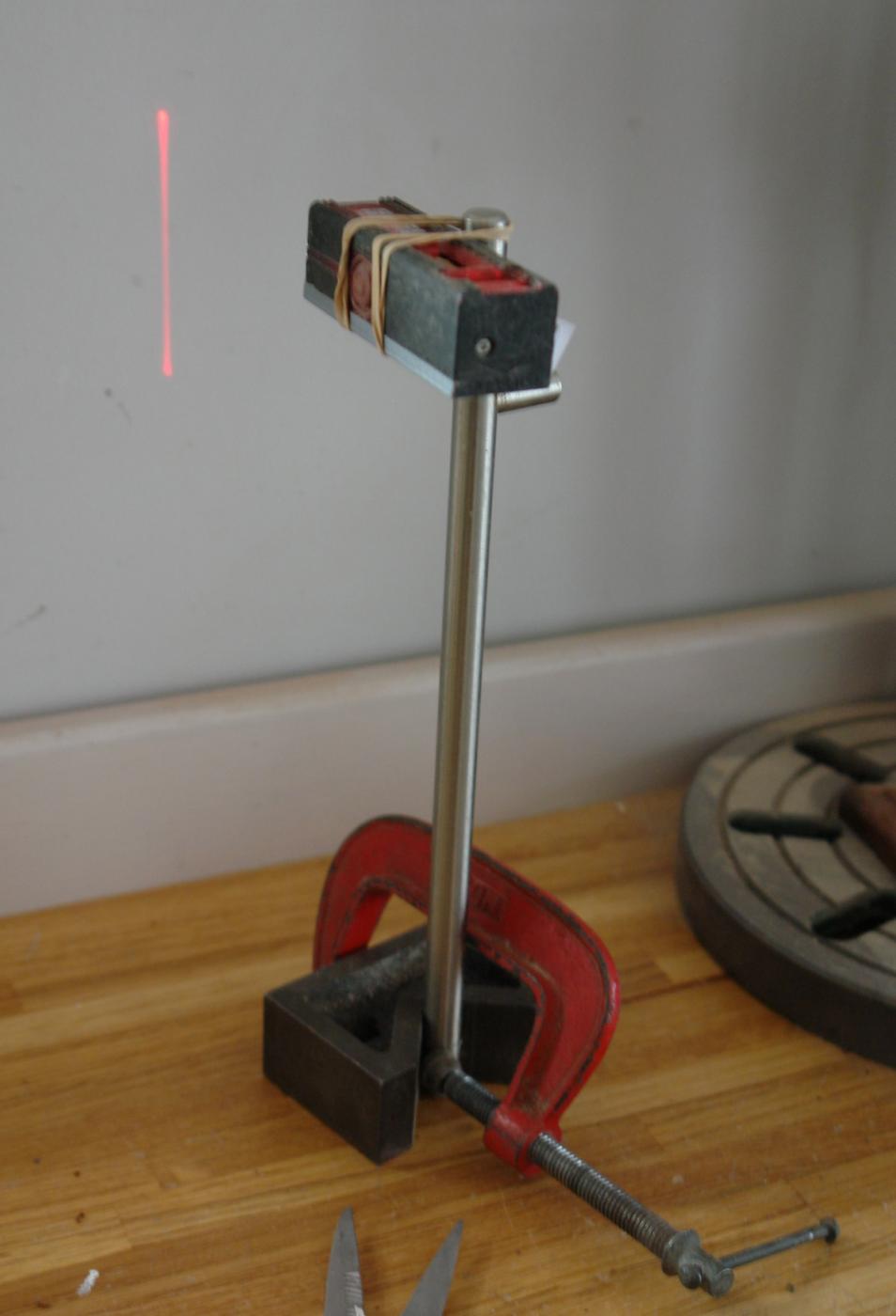
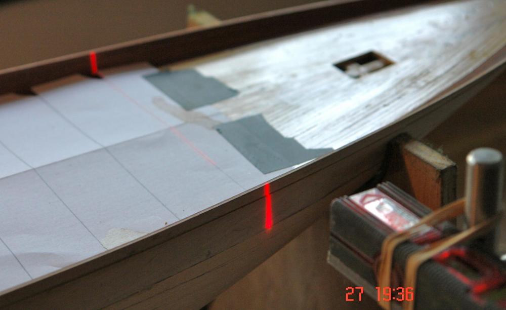
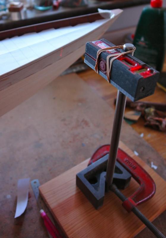
I got a stay of execution on the decorating so managed to do a bit more. The frames on the model plan don't match the frame positions on the original yacht. The frame positions behind the bulwarks therefore have to simulated by gluing on false ribs. The ribs do however need to be truly vertical which is a bit difficult when the deck bows from stem to stern with a pronounced rise at the stem. Obviously taking a reference from the deck wasn't an option. I decided the reference had to be taken from the workbench but it wasn't immediately obvious how I would transfer a vertical line from the bench to the inside of the bulwark. A bit of thinking prompted the following solution. The key component is a christmas stocking quality laser line level. I mounted it on a v block with a vertical post clamped in place to hold the laser. With a bit of shimming I adjusted the laser to cast a vertical line on the wall. This was then used to transfer vertical lines on to the inside of the bulwarks (using the laser line to as the guide for drawing vertical pencil lines) The horizontal positions of the ribs were transferred to the deck using a template. The ribs were cut from .150" x .150" mahogany plank (cut using the slitting saw). Each one had to be shaped on the disc sander to fit the changing profiles of the bulwarks / deck. So far so good!


-
Hello Nils I agree, its very satifying when the planks nest well, recourse to filler is avoided and the sanding enhances the finish. In this build all this effort will be lost under the 2nd planks - but the pleasure is knowing what lies beneath. Regards Keith
-
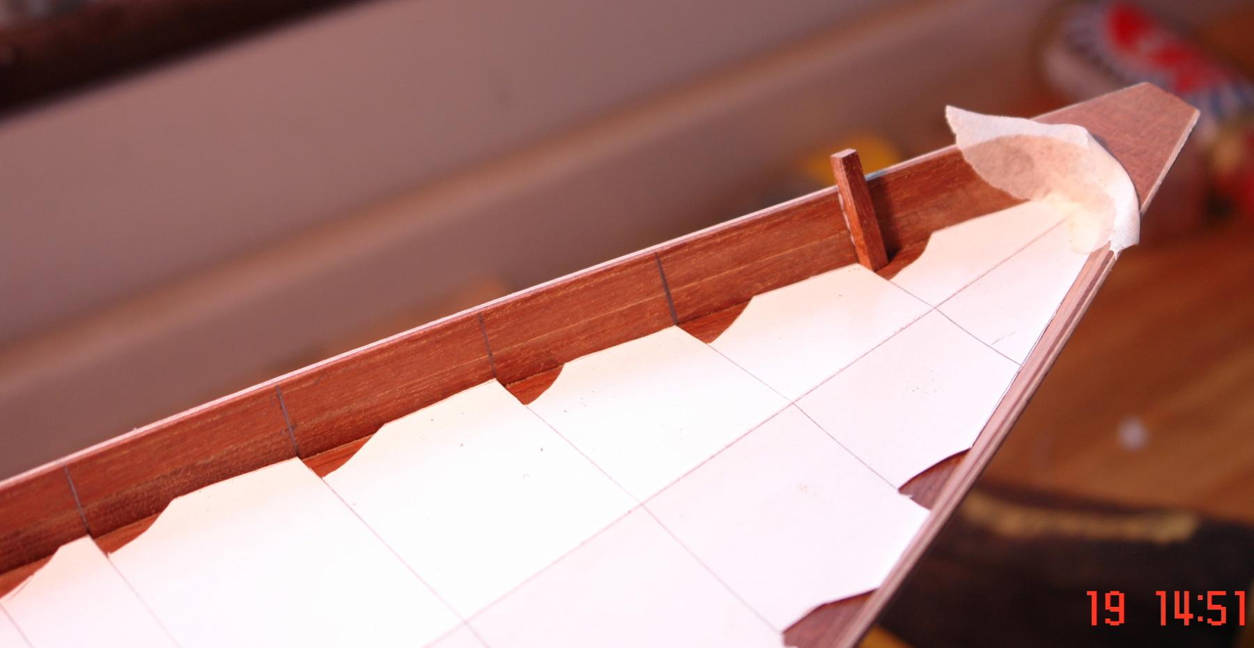
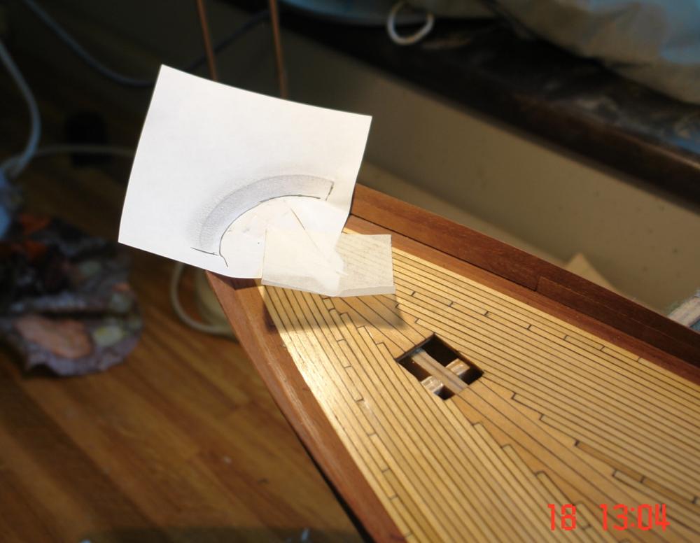
Praying for Rain! Its been some time since my last post. My dear daughter purchased a flat in London in a property built in 1880. It needs a degree of refurbishment and I have been appointed to the post of chief joiner/painter. With that and the garden bursting into spring life I have had little time for my favourite pastime. However today I was at home and thankfully it rained so the yacht took a minor step forward. I needed to mahogany plank the inside of the bulwarks to represent the detail of the original. See photo I cut the planks 12"x0.2"x.032" on the circular saw using a .032 thick zero kerf slitting saw blade. The finish was almost polished! I needed 10 planks to complete the whole process. I used paper to create the template for the stern. Having had my modelling fix I now return to house refurbishment - yawn!!!!


- 882 replies
-
- 11
-
-
Hello Kees Nice work on the ladders. How did you prevent the preceding rung de soldering when you soldered the next adjacent rung? Did you use a heat sink?
- 434 replies
-
- 2
-
-
- pelikaan
- beamtrawler
- (and 2 more)
-
Hi Michael The machining sequence for the goose neck was really interesting. Working out how to manufacture small metallic items is an endless source of fun and your result was excellent. Well done.
-
Hello Keith Cutting of frames is are much easier if you have a scroll saw. I think I will buy one before doing the job again. Hi Pete / IMack - thanks for the positive comments. I think the build will go slowly for a while - house decorations are moving up the agenda and can only be put off for so long.