KeithAug
-
Posts
3,986 -
Joined
-
Last visited
Content Type
Profiles
Forums
Gallery
Events
Everything posted by KeithAug
-
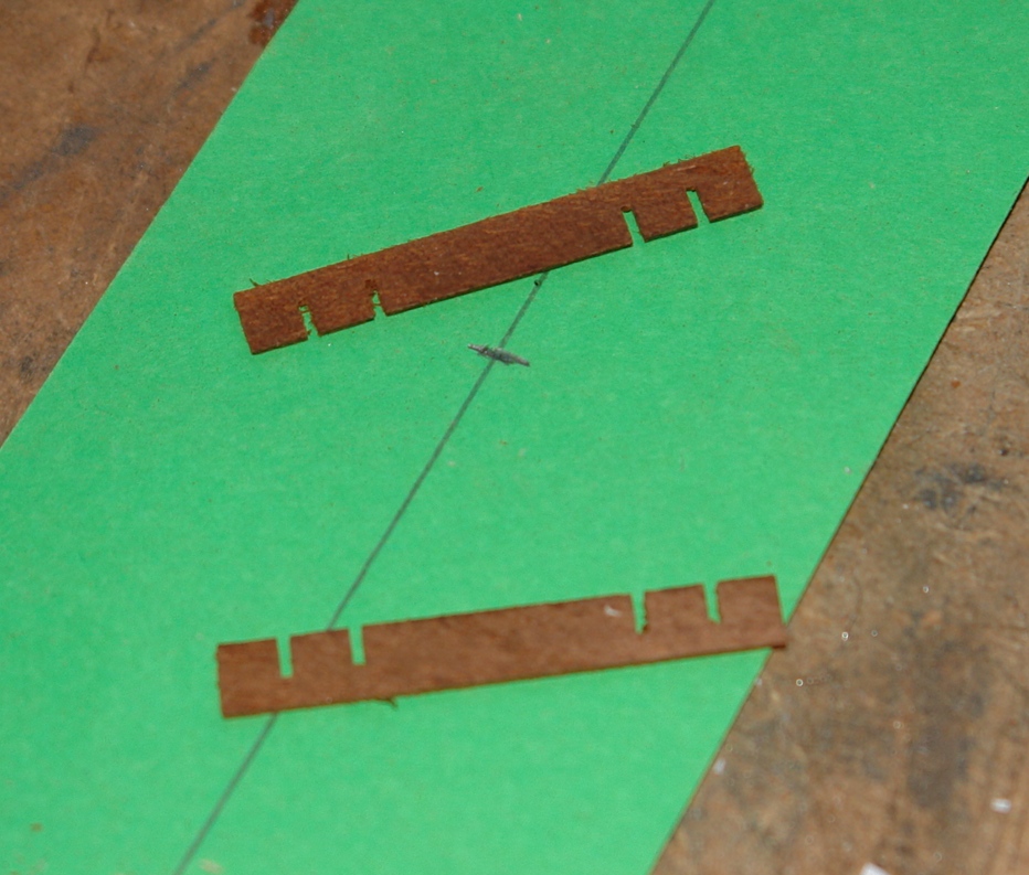
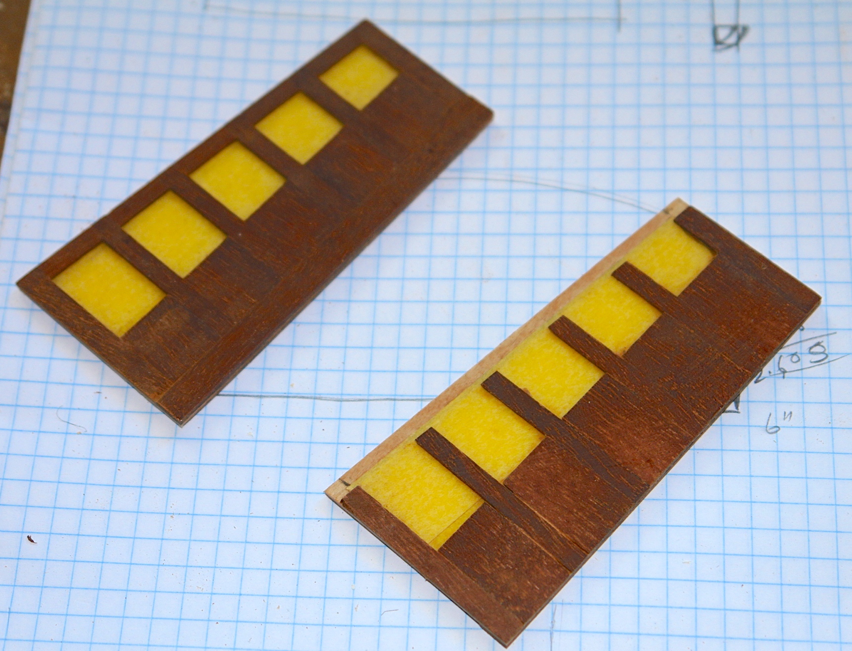
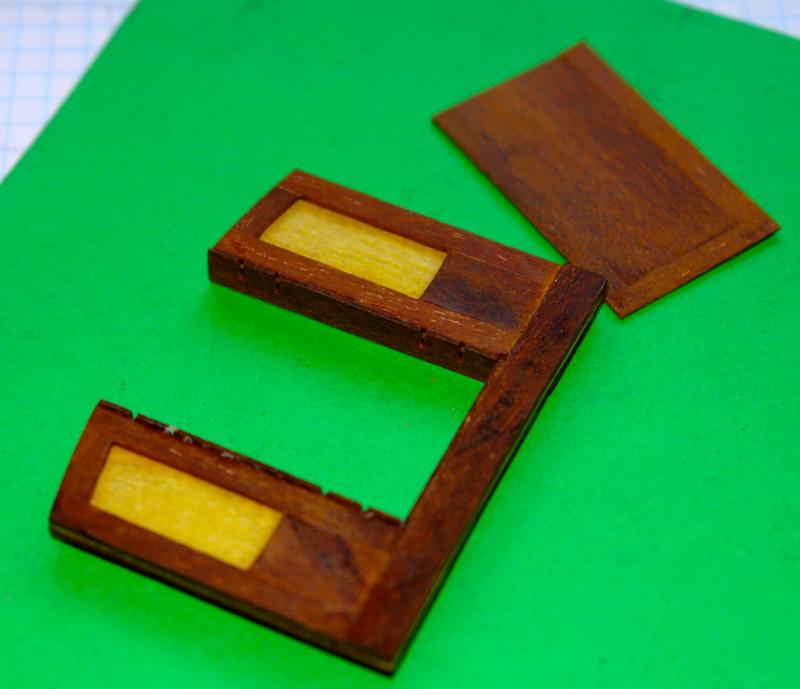
 The exterior of the crew hatch now has 4 coats of poly. I guess one more coat will do it. I will also need to paint the inside I have gone back to the deckhouse and had a go at the deckhouse doors (2 off). I started with the door jambs. These were made over wide with the positions for the hinges accurately cut on the table saw. The hinge cuts were made in a plank before strips were sliced off. Thus ensuring the the position of the hinge cut outs were identical for both doors. The strips were glued to the frame and once dry they were reduced to the correct width. Effectively leaving 5 separate pieces of door jamb on each side. The hinge cut outs were then removed with a chisel. In parallel I made the doors. Both doors were made joined - they will be separated later.
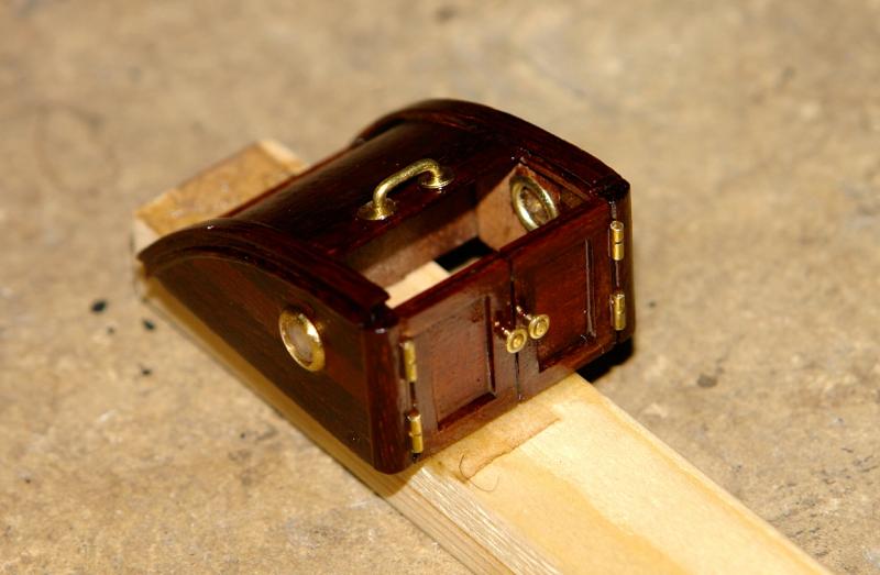


- 882 replies
-
- 16
-

-
Beautiful work Alex. I was intrigued by the press for the hull plates. You refer to 'poverhnostyami.Izgotavlivayu stamp" but i can't find a translation. Did you make the press and if so how? Keith
-
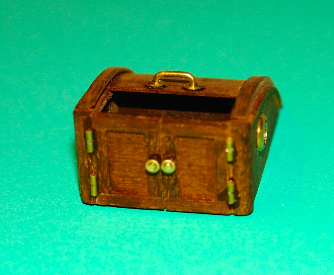
Michael /Bob Thank you for continuing with your support and comments. I have now coated the hatch with a few coats of poly and its looking quite smart.
-
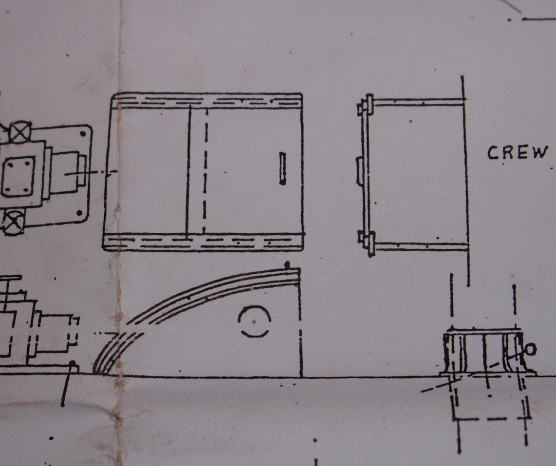
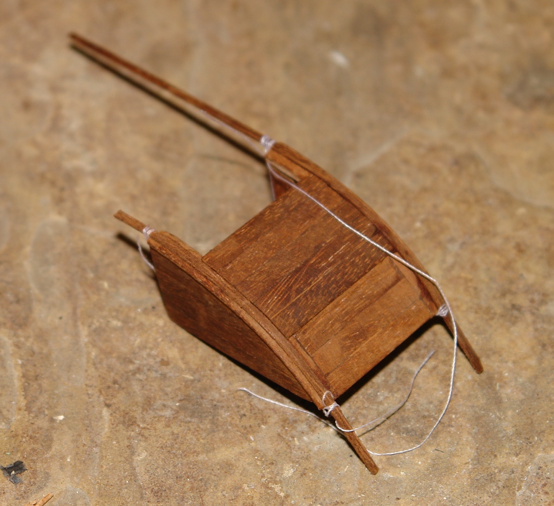
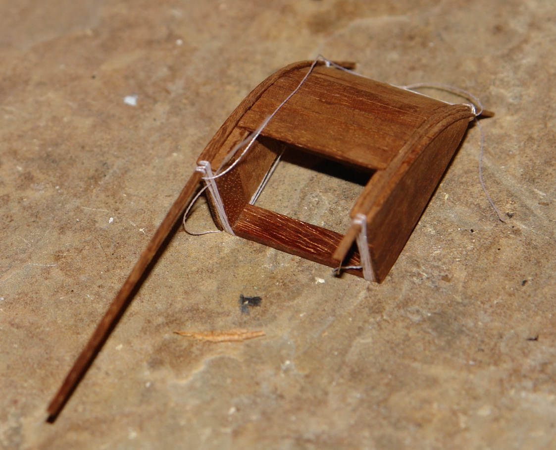
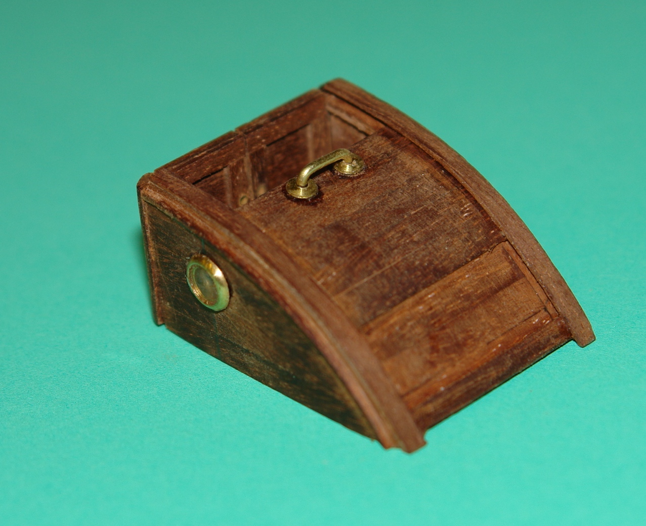
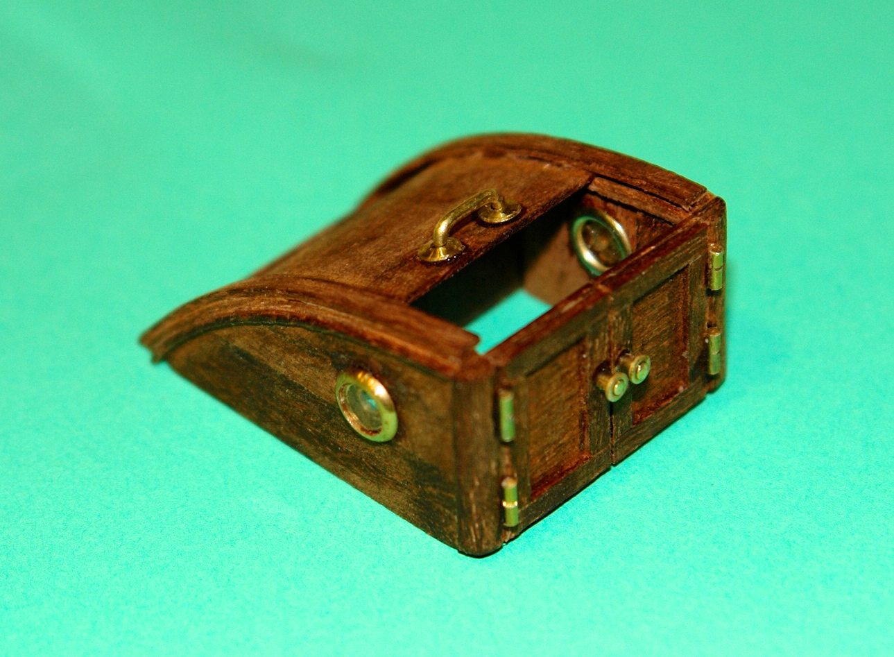
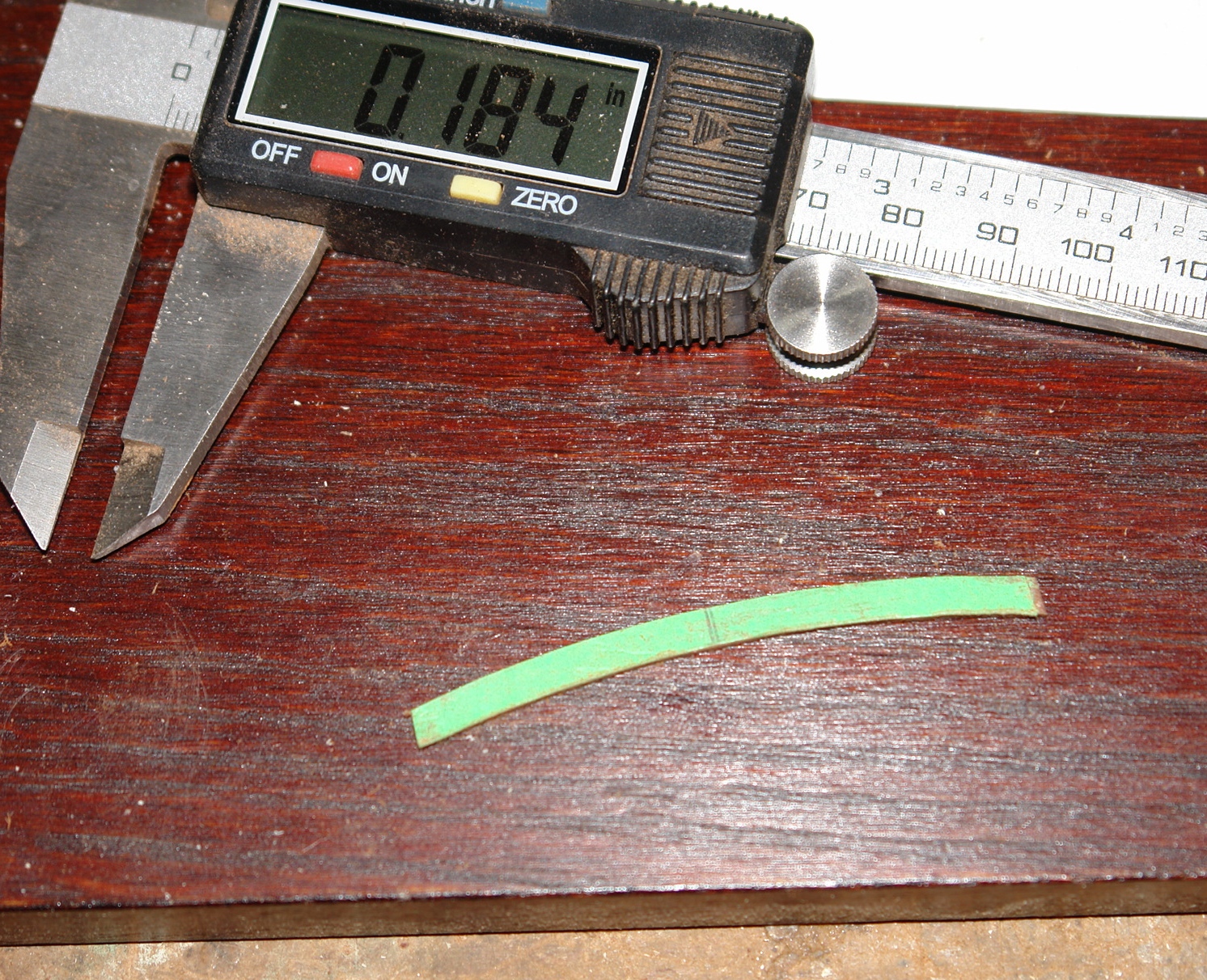
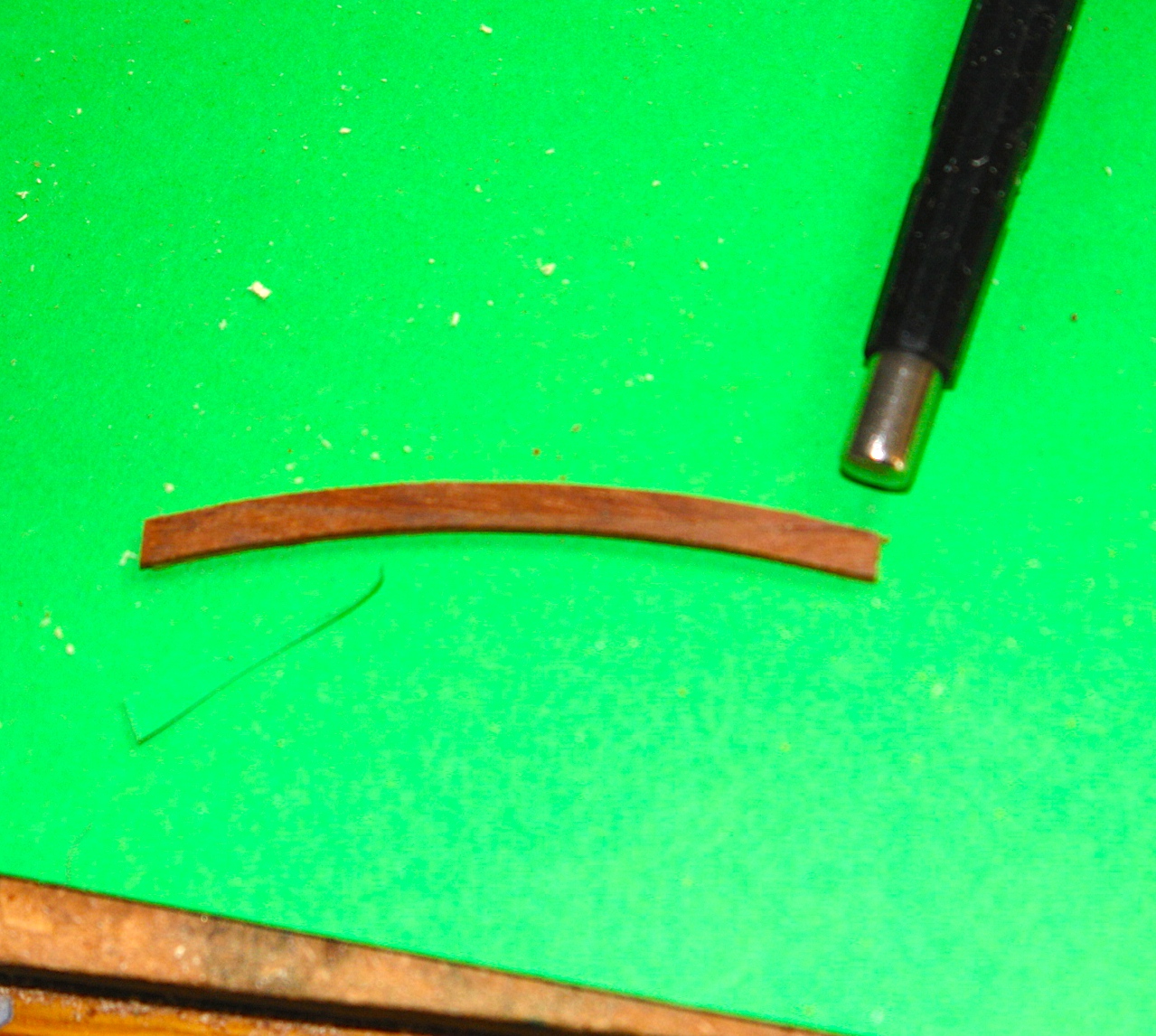
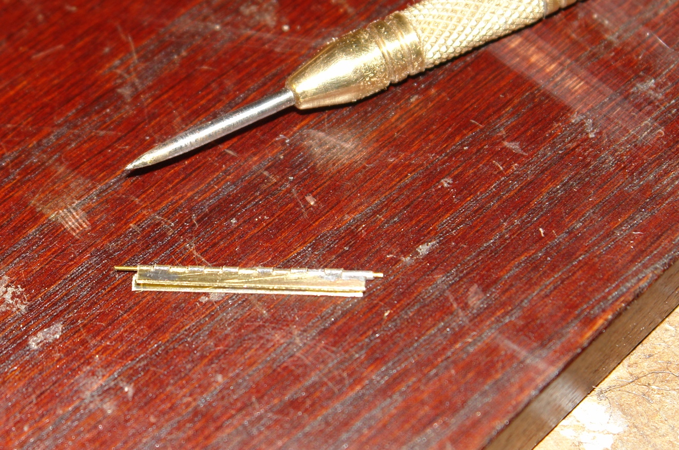
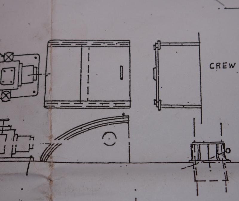
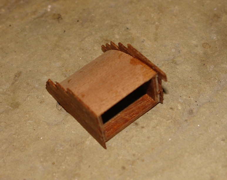
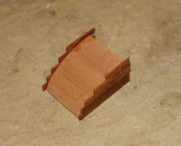
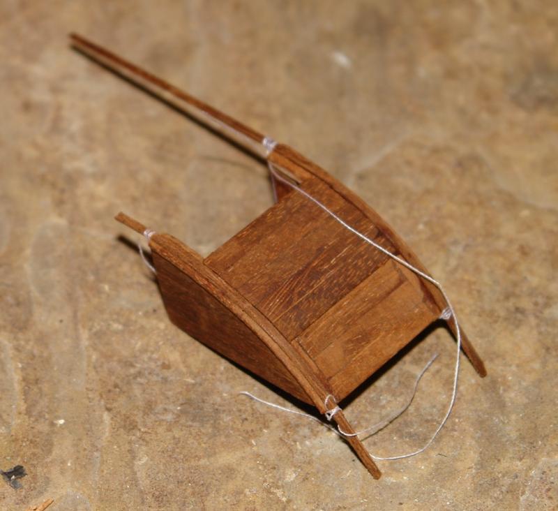
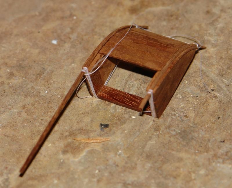
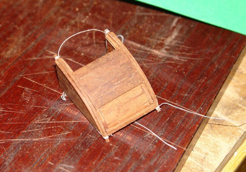
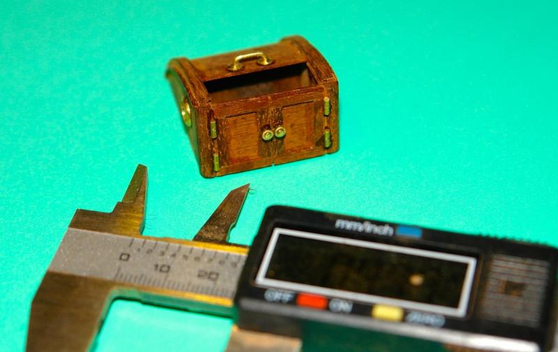
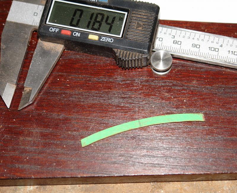
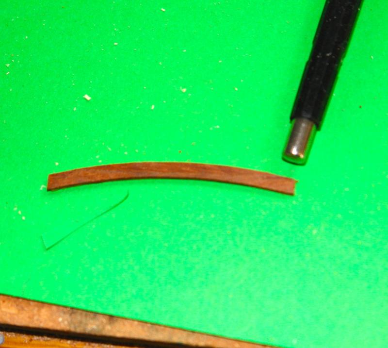
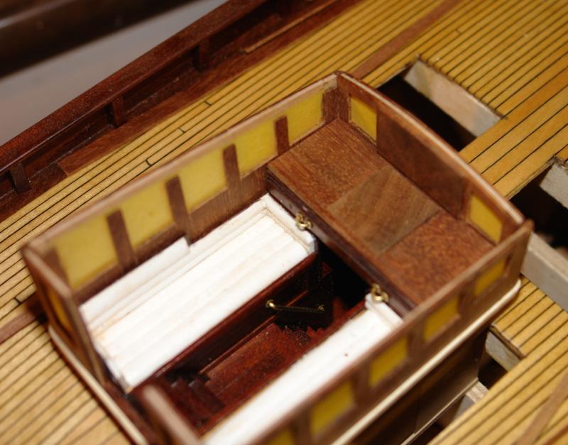
I decided to have a bit of a diversion from the deck house and made the crew hatch. The detail on the plans was really quite scant. I tend to rely on internet photos where the plan is less detailed than desirable, however in the case of the crew hatch virtually nothing was available. I was left to rely on the "how would I have done it?" approach. In particular the doors are a figment of my imagination. After all if they don't exist it's going to be pretty wet below. I started with the sides - cut to shape from 1/32 inch ply and then clad in mahogany. I decided not to make the hatch cover mobile but represented it partially open - to give a bit of a view inside (although not much to see) I did however make the hatch tracks correctly as a "c" section. The "c"was constructed from 3 planks each .030 inch thick. To get the curve the wood was soaked in boiling water and then the body of the hatch was used as the former. Note the wife's cotton used to hold the planks in place while drying and thereafter gluing. Some time later all was complete and ready for the poly. This gives an idea of scale. The callipers are set to 1 inch.


-
John Only the mechanical ones. I never really got electronics being from ABC (the "age before calculators"). My only concession to technological advancement was speeding up my slide rule by dusting it with talcum powder. Maybe I should enrol in a crash course in miniaturised electronic instrumentation!
-
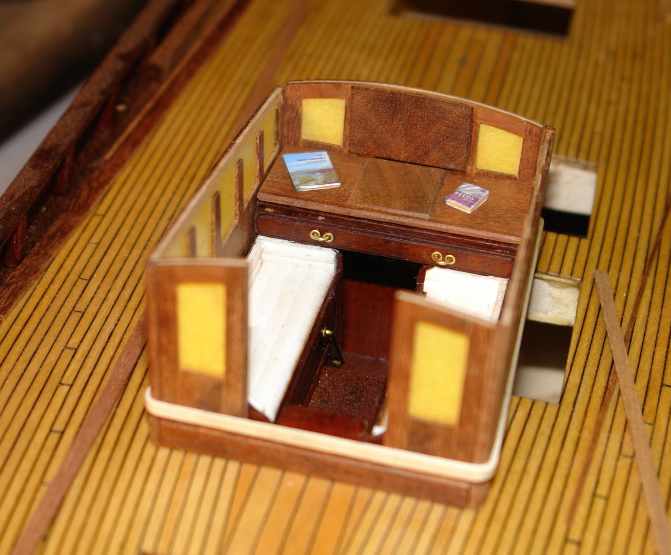
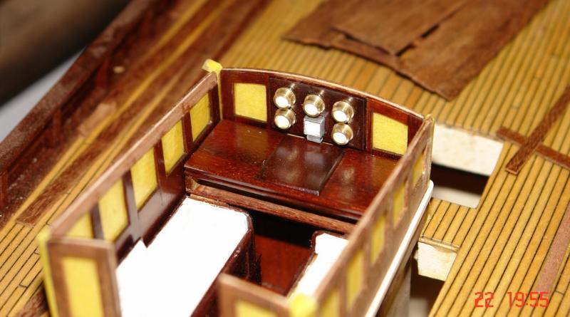
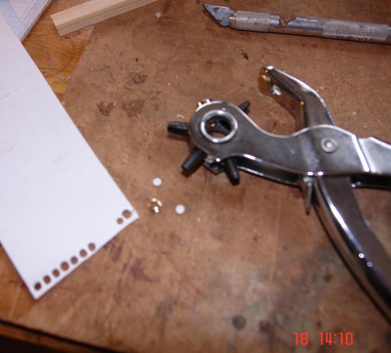
Hi Michael - I don't have holly, its difficult to get over here, I could cut down the tree in the front garden though! I finished painting the internals of the deckhouse prior to assembly and also finished the instrument panel. The mahogany came up a treat. Looking at the photo I have just realised that I have left the chart drawer out. The gauges are turned from .25 inch brass bar and the face is plasticard punched out with a leather hole punch. The square gauge is cut off from .25 inch square section aluminium tube.
-
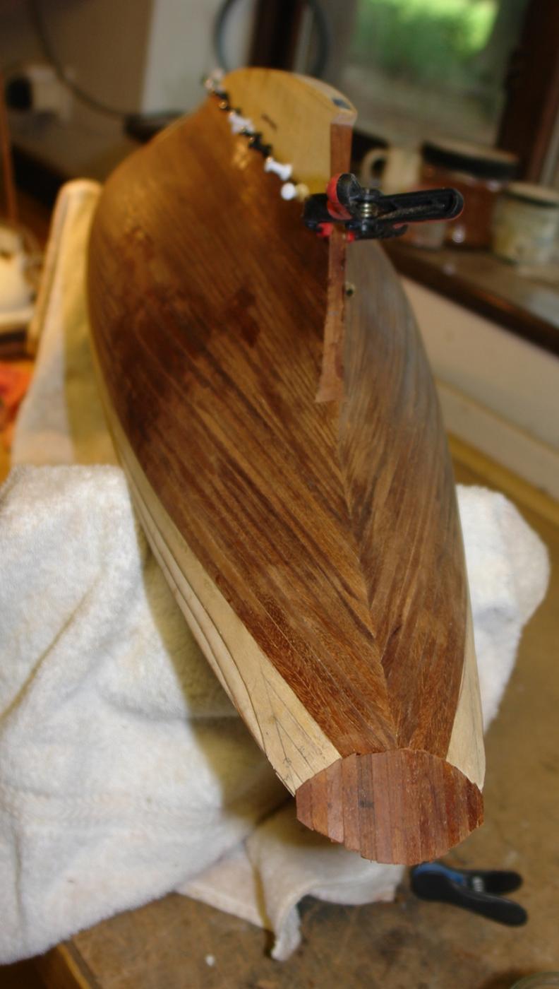
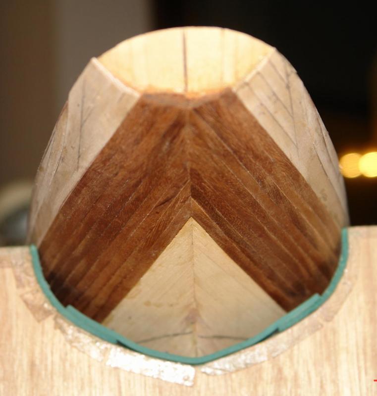
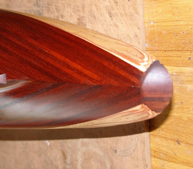
Julie - re shaping the transom. Yes, as you say, one approach to the transom wold be to use card folded along the centre line and then cut. On Altair I actually drew the shape on card using a bit of geometry. However Altair isn't as sleek as Endeavour so the folded card method may be better.
-
Druxey Thank you taking time to look at my log. Your generous comments are much appreciated.
-
Michael Some of the original paintwork looks a bit rough and ready - is it just the photo magnification or is it a fairly indifferent brushed finish? Your biggest problem may become toning down your normal quality!
- 749 replies
-
- 6
-
-
- albertic
- ocean liner
- (and 2 more)
-
Hello Mark. Photo's of the cabin incorporated in the display is a good idea that I hadn't though of, thank you for the prompt.
-
Hi Julie That looks much better doesn't it. Im surprised they didn't advise it in the kit instructions as it would have made the stern simpler to plank. Keith
-
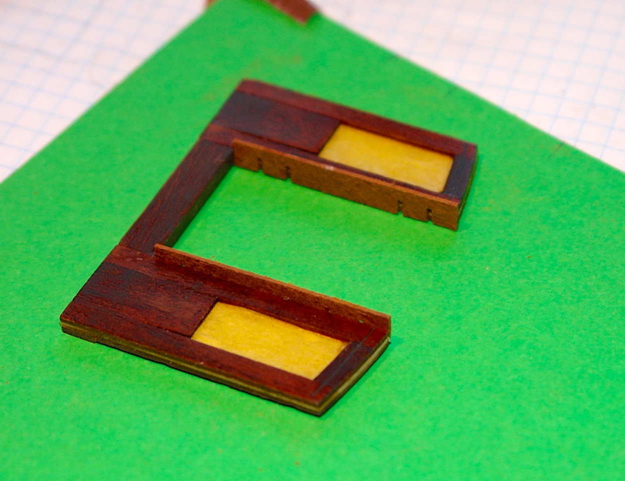
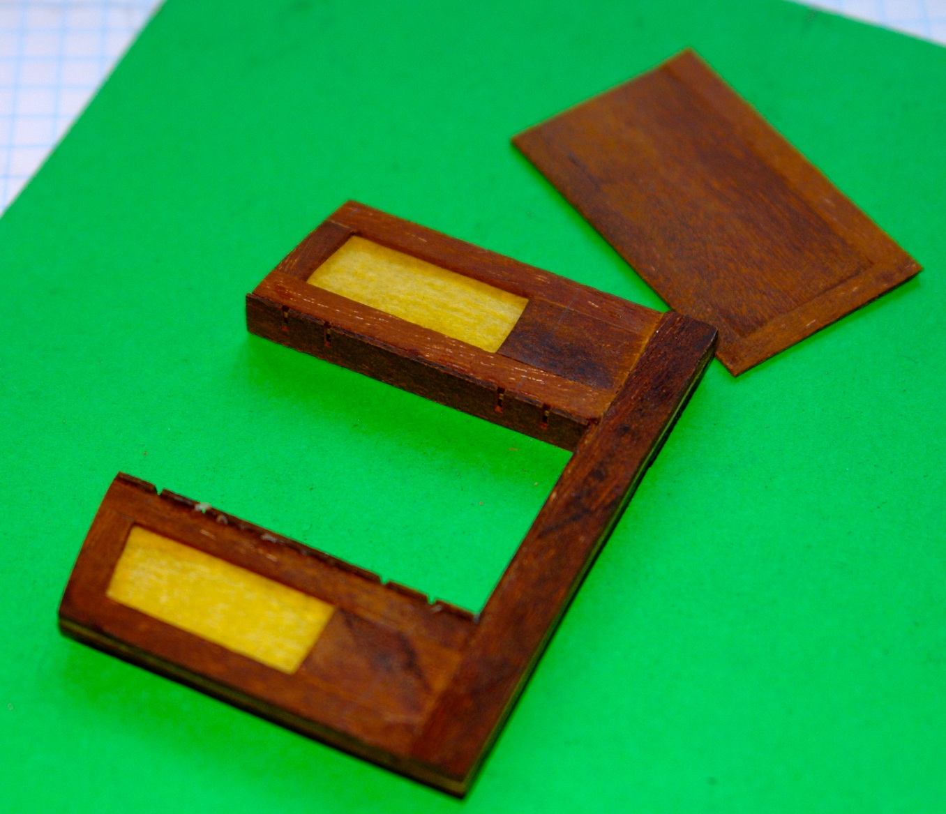
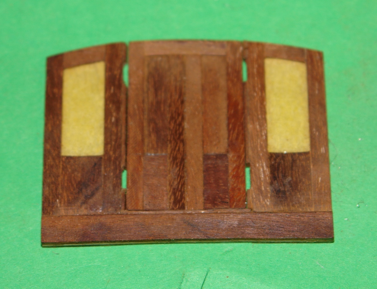
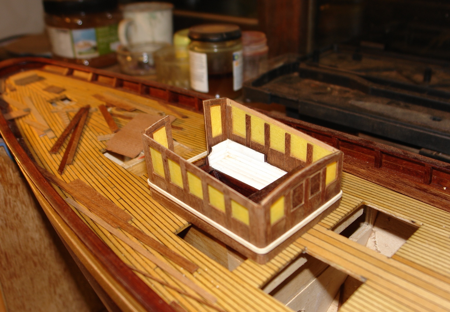
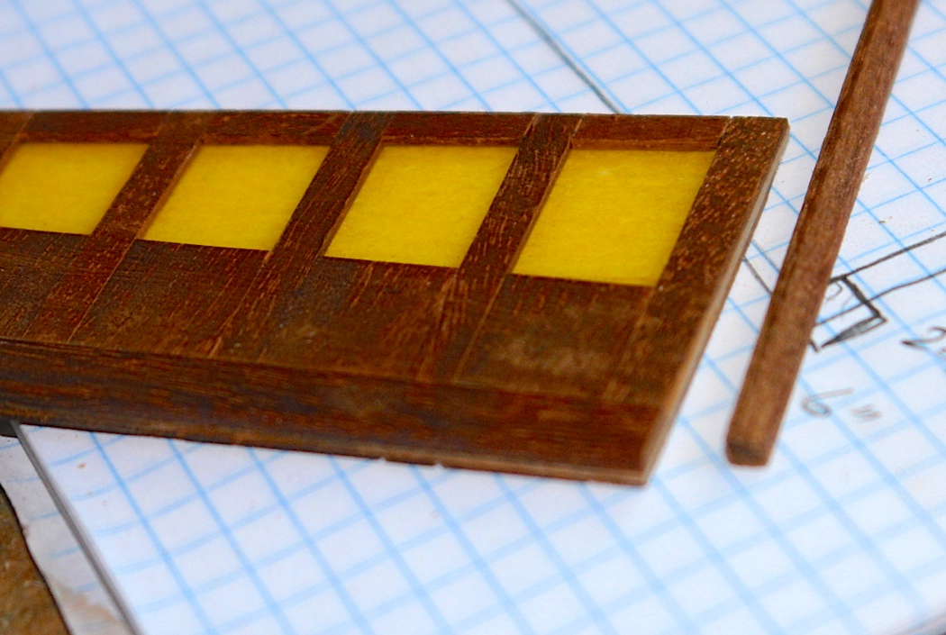
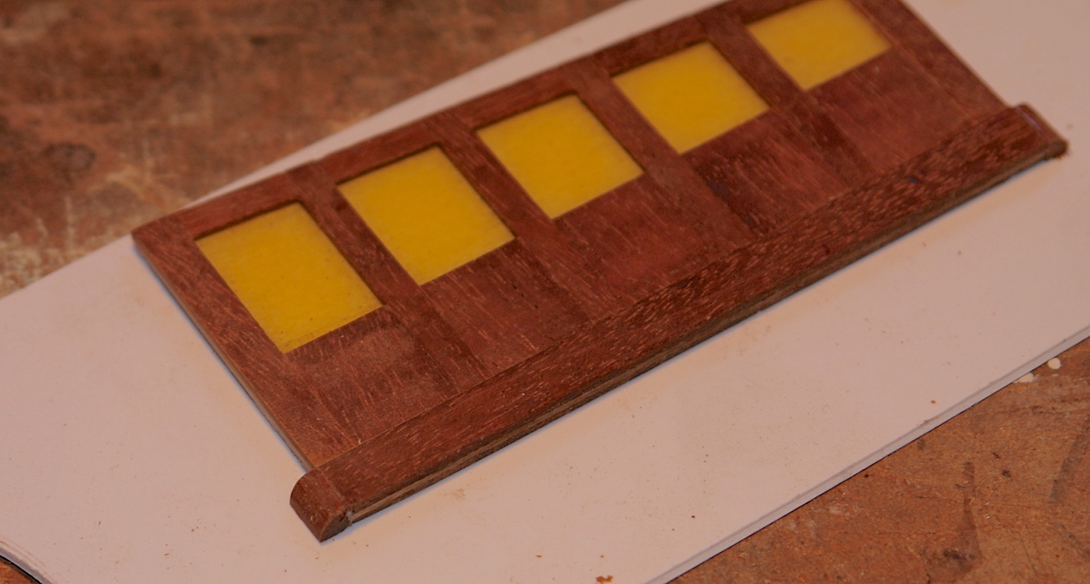
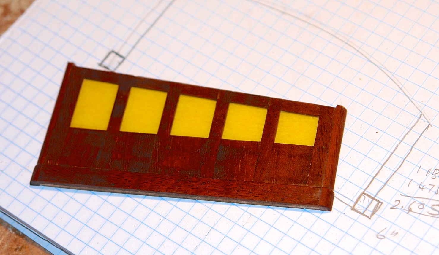
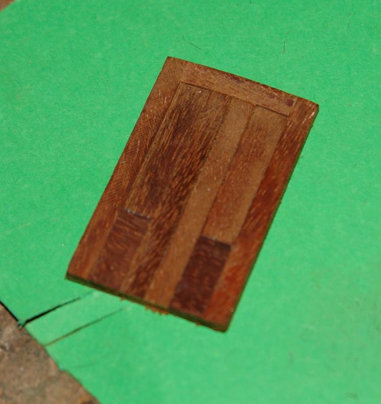
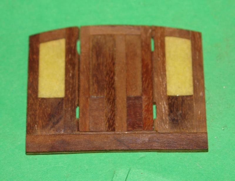
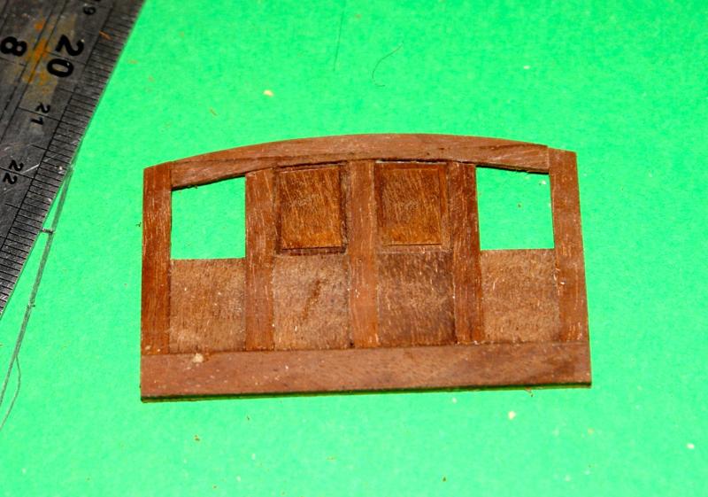
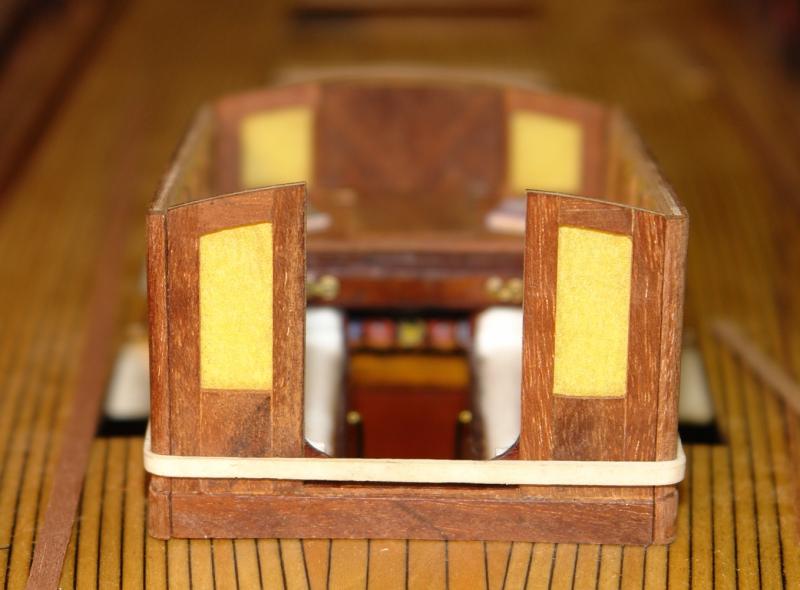
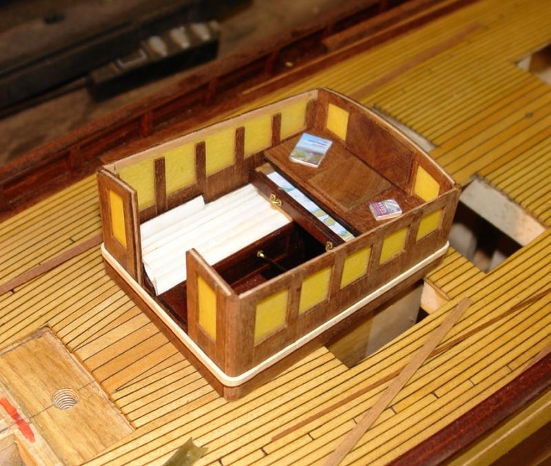
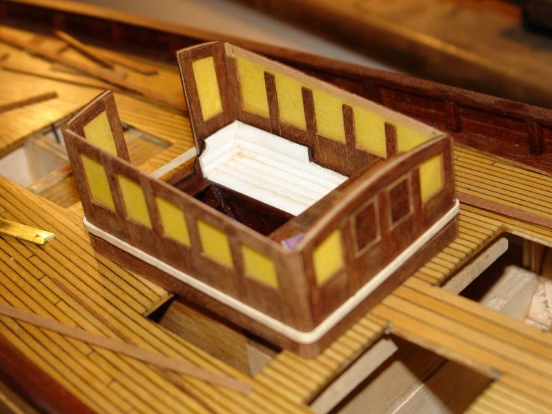
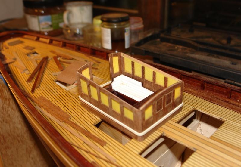
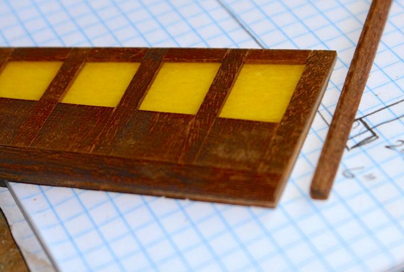
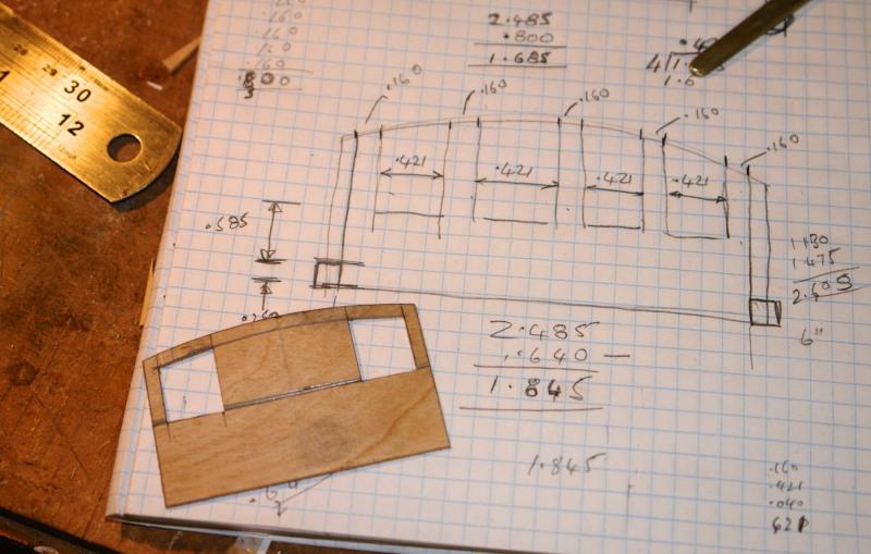
A bit more progress on the cabin. The front and back were constructed along the same lines as the sides - made a bit more complicated by the curve at the top. I remeasured the curvature of the top which although made at a radius of 4 inch had sprung out to a radius of 5 inch. Not a problem but I was glad I checked before making the front and rear. A few photo's------ I templated the top mahogany strip before shaping it on the disc and spindle sander. The front has 2 window and 2 inset panels. The rear has 2 windows - i still has yet have to attach the door jambs with the hinge cutouts. The chart table top was also made and attached above the chart table drawer. Also the instrument panel facia was made and attached to the inside of the front. The panel itself is made from 2 pieces of mahogany with the grain matched as a mirror image. Not easy to see this but it felt good doing it. A few more images with the walls held in place by an elastic band at this stage.

- 882 replies
-
- 13
-
-
Julie I think the form of the transom on the kit is incorrect and it should be better defined. The underlying issue is lack of definition in the shape of the frames. I didn't spot the issue when I was building but if I had I think i would have created the definition at the 1st planking stage and then 2nd planked the transom axially - i.e fore and aft. this is what I did on altair.

-
Julie - thank you for your kind words. I keep looking at your build hoping to see how you are developing. You seem to have quite a full life in Florida. Maybe what you need is long winter nights of snow wind and rain to keep you focused - it is currently throwing it down here with 80 knot winds forecast for later tonight. I bet you are wondering if its time to break out the cardigan, while planning the Thanksgiving barbecue. On reflection maybe you are better off with the distractions of the Florida climate.
-
Hi Bob I keep thinking I would like to build an Edwardian steam launch - including building the engine - I have built a steam engine previously and enjoyed the process. I look forward to seeing your build - computer willing!!!!!!
-
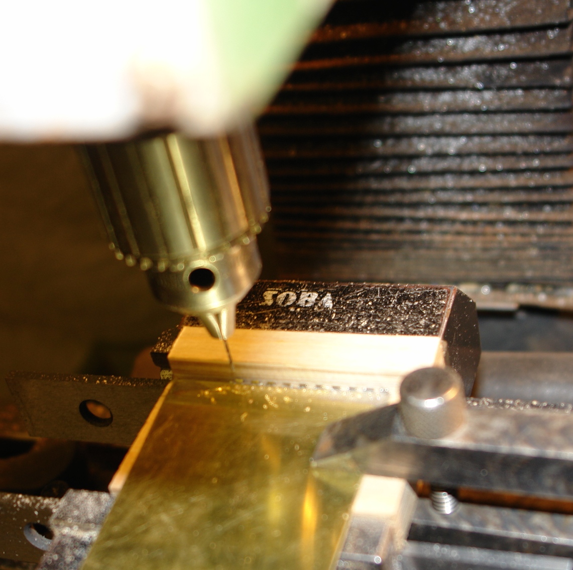
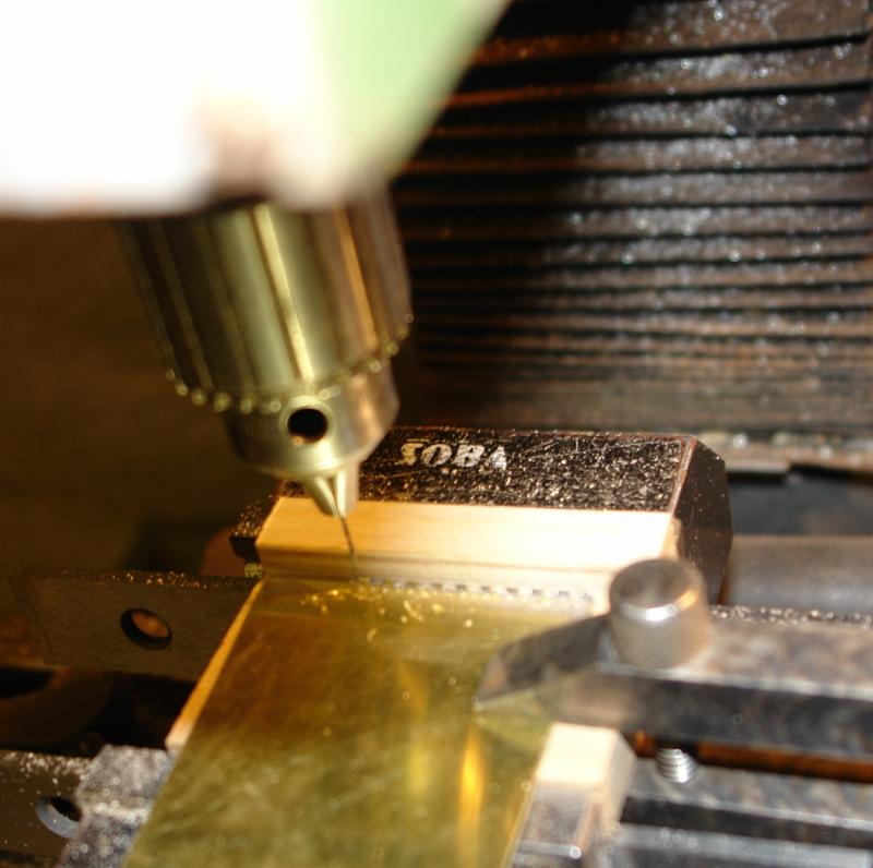
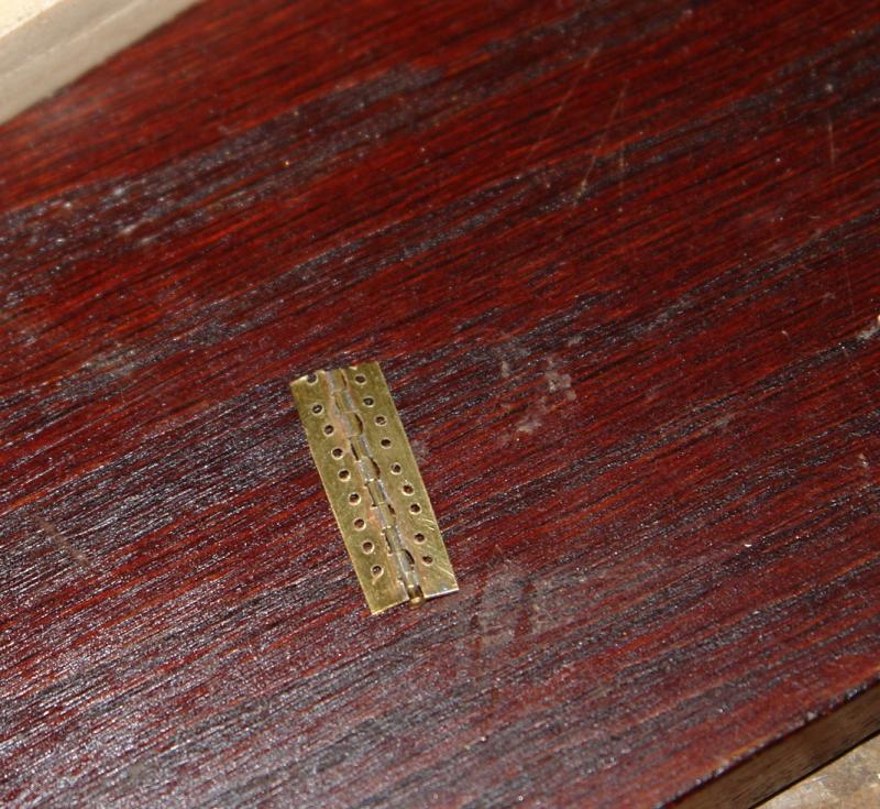
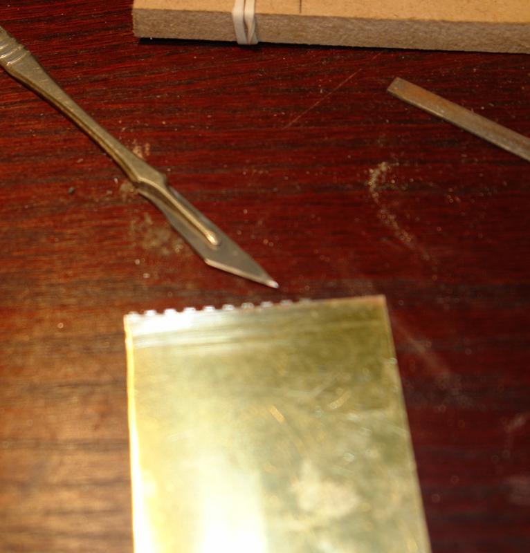
Thank you Michael and John. I think I'll try it once more taking a little more care on the soldering. Finishing the hinge process:- Having made the basic hinge pieces I decided to try drilling holes for attaching the hinges to the door posts. I didn't have a centre drill small enough so used a .025 inch twist drill, hoping it wouldn't drift off. Hope was in vain and this aspect of my plan was a failure. Finally I parted off using a slitting saw. The first hinge worked but was a bit messy. I decided to dispense with drilling the holes on the mill and will drill them by hand next time. The second attempt was posted earlier - a coupe more photos here.

- 882 replies
-
- 10
-
-
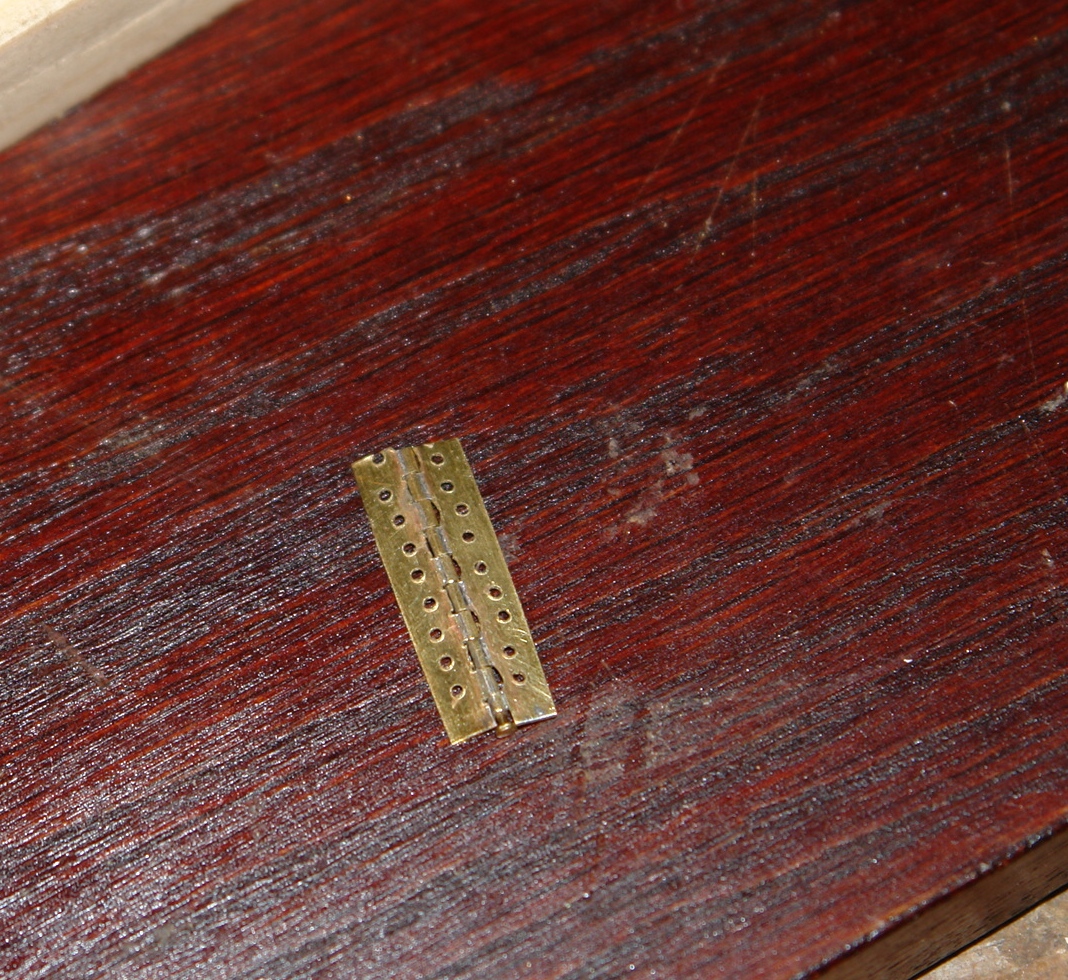
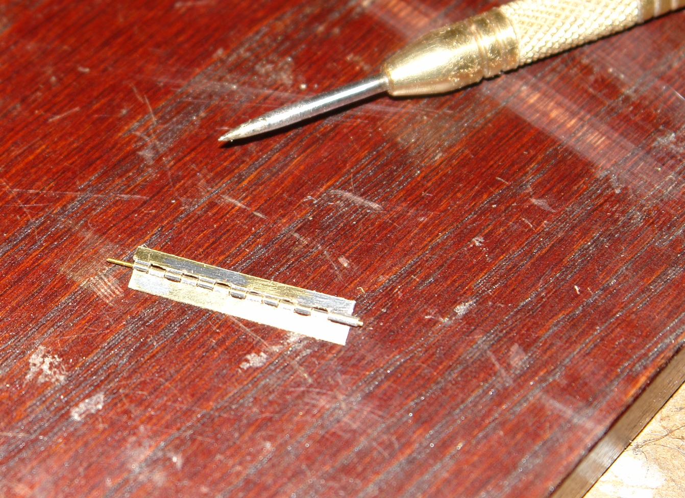
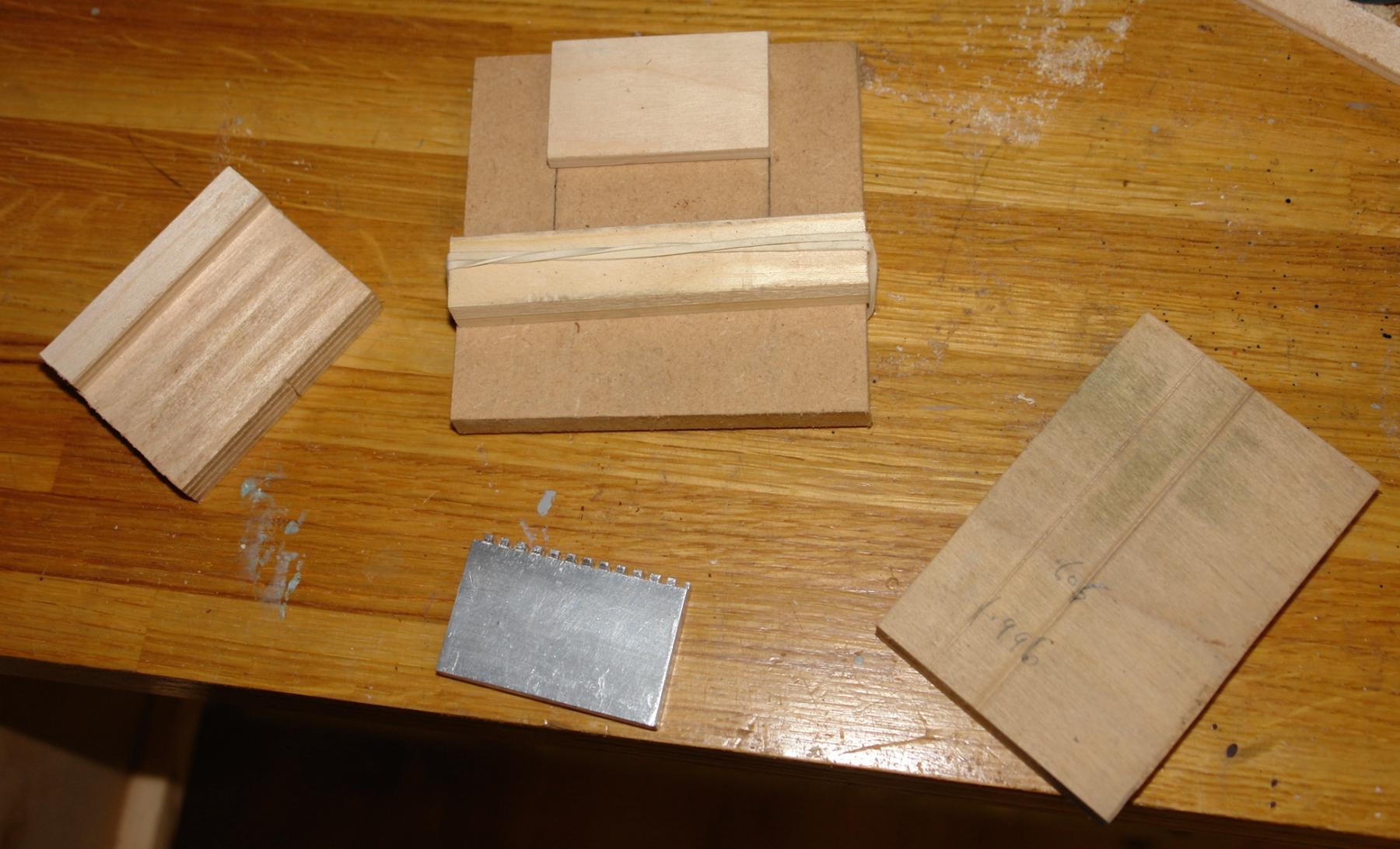
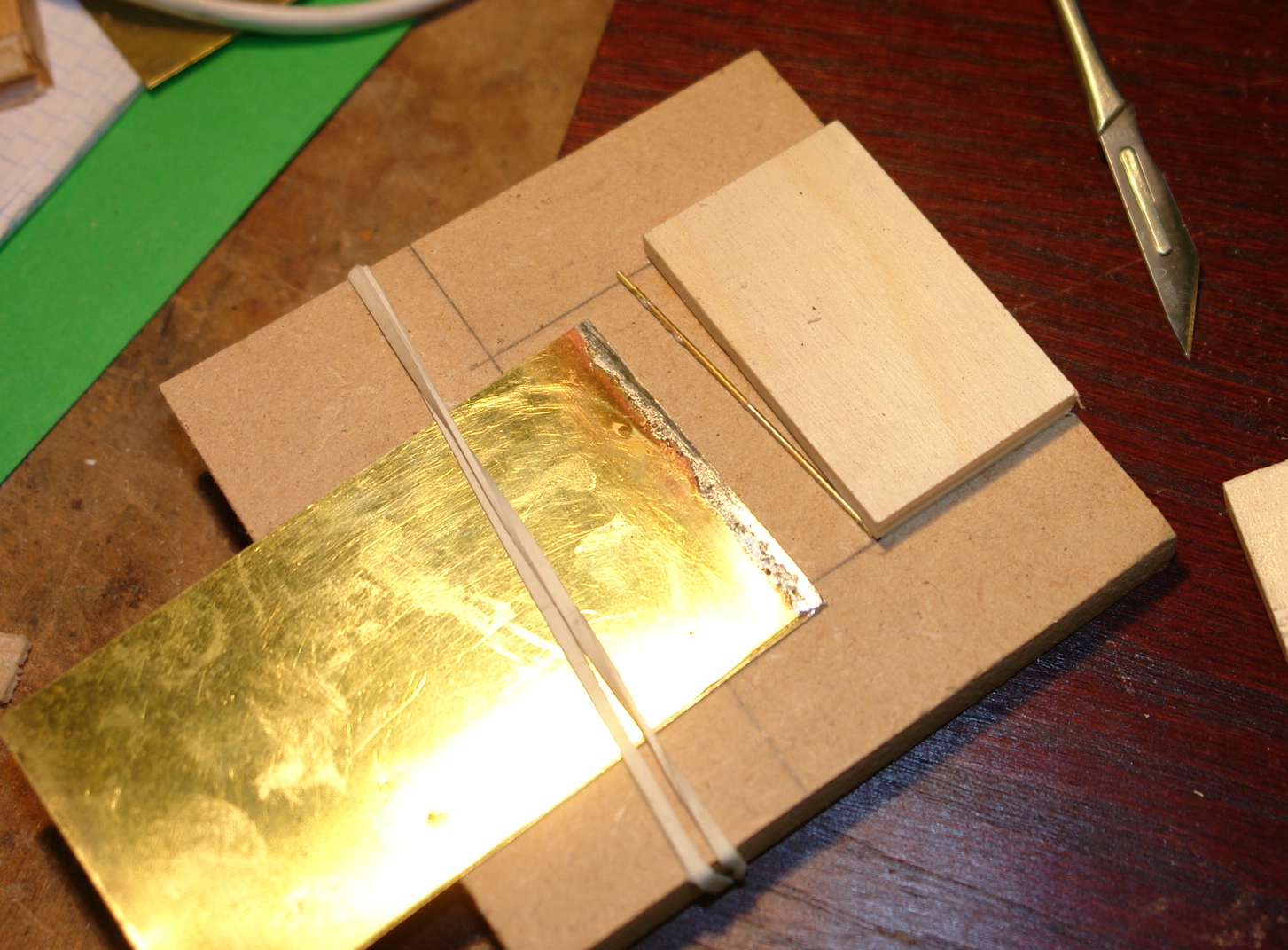
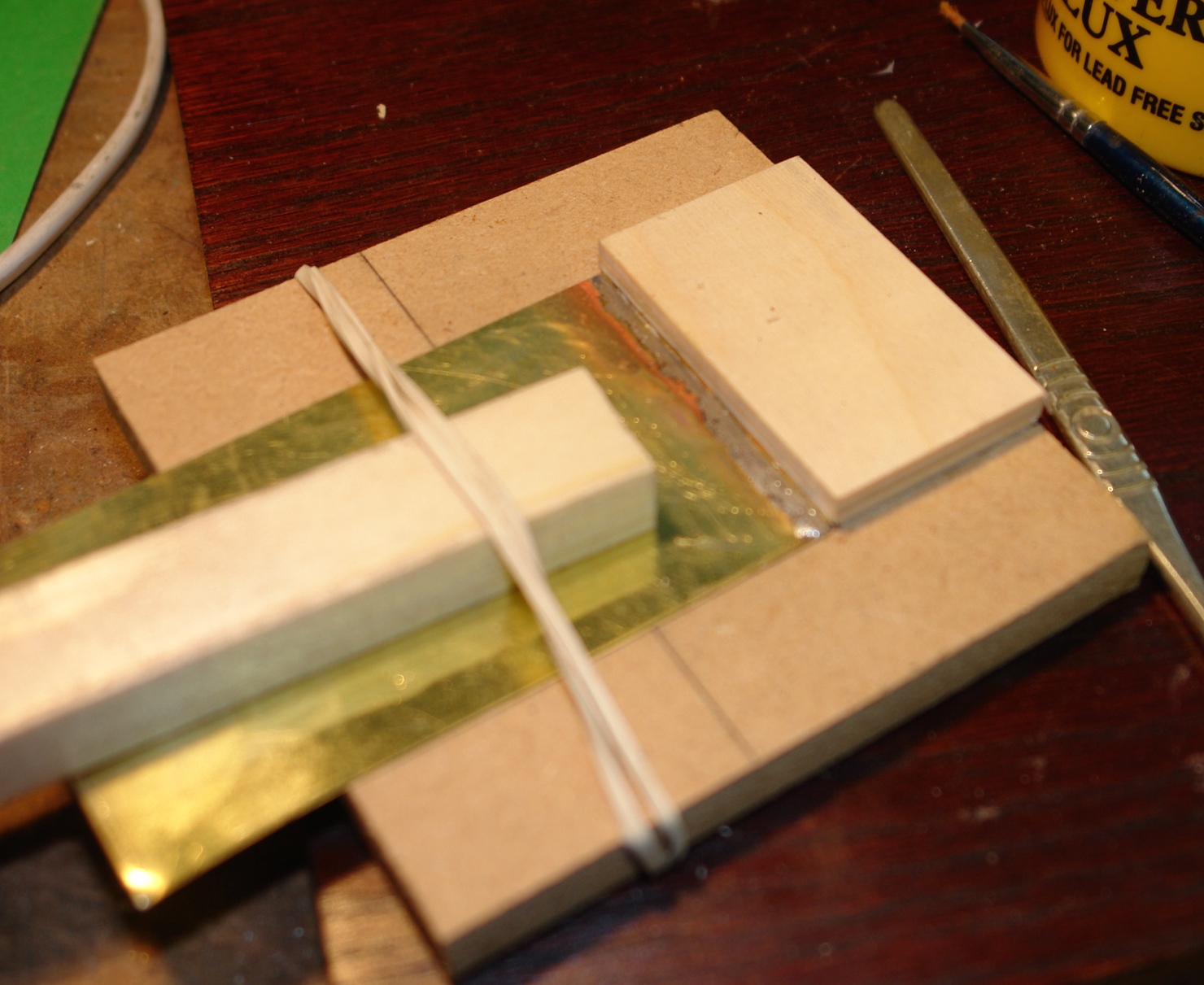
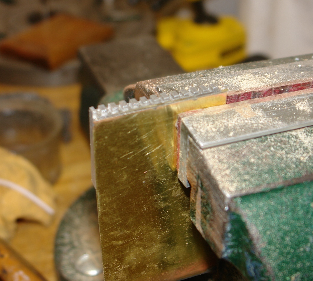
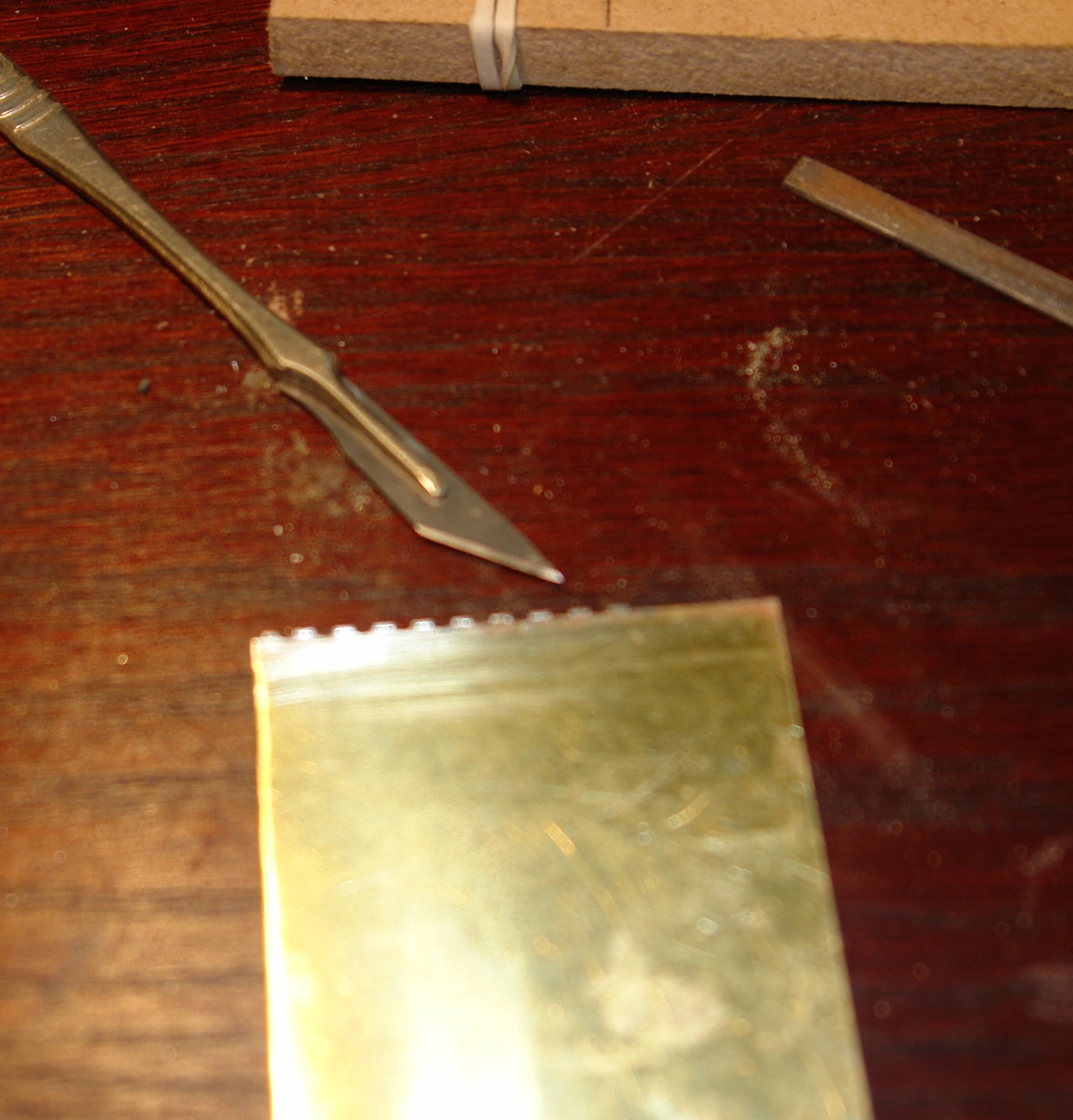
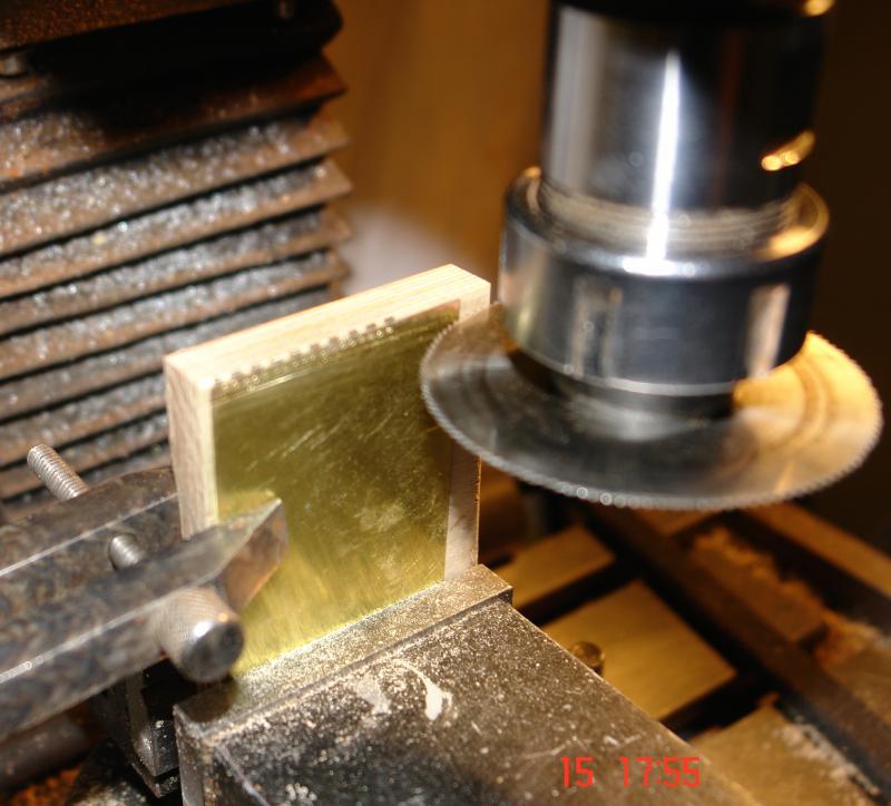
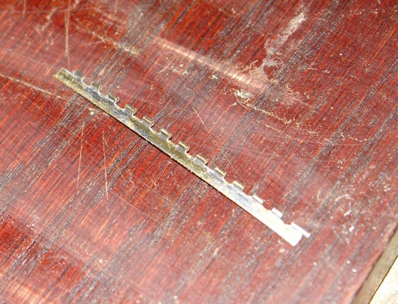
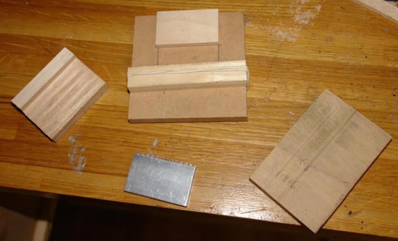
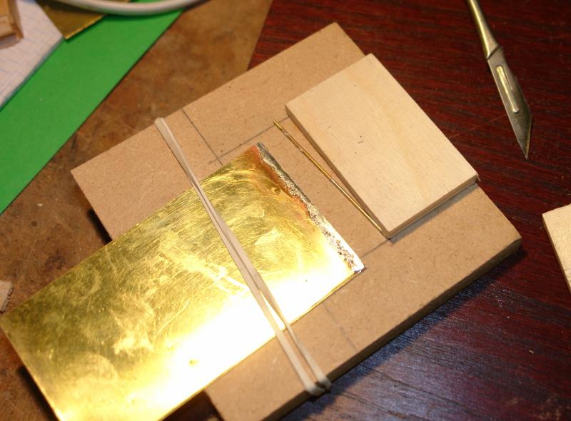
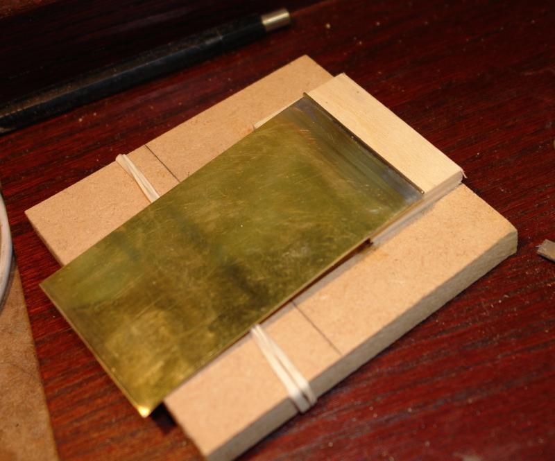
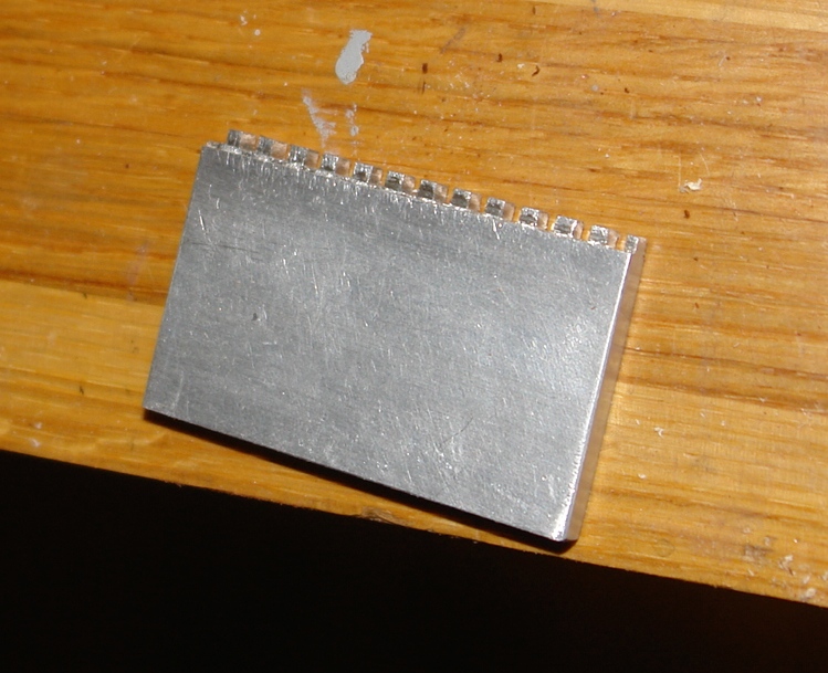
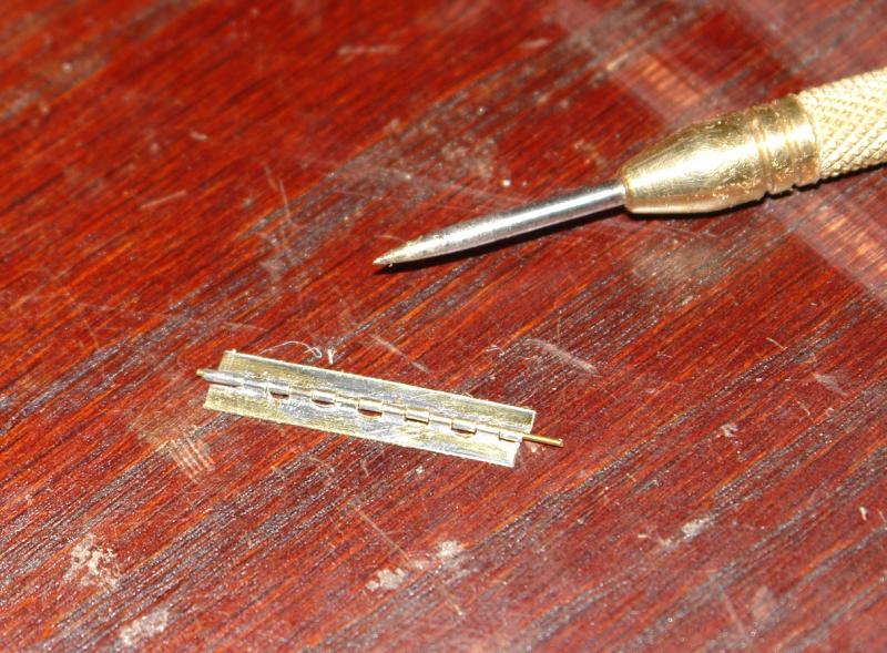
I made a start on my hinge experiment. The hinges need to be .240 inch long by .100 wide when closed. Having decided on an approach I made 4 jigs - 3 simple and one a bit more complex. Their uses will become clear further on. I started by soldering .040 inch OD brass tube to .012 sheet. Both the sheet and tube were "tinned" with soft solder prior to joining. The 1st jig was to assist soldering - simply a recess to hold the tube down while the sheet was pressed against it. A bit difficult to see but here the tube is attached and the soldering cleaned up with wire wool. The trickiest bit of making the hinge involved accurately cutting the tube before removing alternate tube segments with a needle file - the cutting / filing jig worked very well in enabling this operation. The photos are proving quite difficult because of the scale and the reflective materials. I hope they are good enough to illustrate the process. I need to go and make dinner but here is the 2nd attempt - I have made a "piano" hinge at this stage. It's about 1 inch long and the final hinges will be cut off from this. I will continue describing the process in the next post.


- 882 replies
-
- 11
-
-
I grabbed a couple of hours this weekend to make a bit of progress. I spent some time trying out options for making the hinges for the deckhouse doors. I abandoned this when I released I needed some brass sections which I ordered and I await delivery. I finished off the sides of the deck house by installing acetate windows (.020 thick) and then cladding the inside. I covered the acetate with masking tape to prevent poly contamination whilst painting. I needed to create 1/4 round dowels for the corners of the deck house. 2 different radii of dowels were required .120 and .140 inches. The larger diameter is required at deck level where the deck house wall is thicker. After a bit of head scratching I realised that I could make the 1/4 rounds on the drum sander by first making a square section equal to the desired radius and then passing it in and out of the sander always keeping one corner in contact with the bed. It worked a treat. The base dowels went on first followed by the remainder of the edge - glued with PVA I also made a start on the deck house front.


-
Thanks Michael I was worrying about getting the fold neat (sheet metal work wasn't my best apprenticeship experience) so I came up with a slightly different plan which I will try when I am next home - Friday. If it does not work I will try your method.
-
Thank you John. I am currently wondering how I am going to make working hinges for the deck house doors. They need to be about .160 inch long by .080 wide when closed. I have looked on the net but even the smallest hinges seem to be 3 times this size. The plans suggest using Sellotape for hinges which is neither elegant or durable. I will have to do better.