


Cathead
-
Posts
3,522 -
Joined
-
Last visited
Content Type
Profiles
Forums
Gallery
Events
Everything posted by Cathead
-
 Very nice indeed. I like how subtle they are; the pattern blends into the hull without dominating it. And that first photo of USS Porcupine gave me a chuckle. I'm curious: there are a few stretches where there are none, why is that? For example, in your last photo, upper middle, right along the waterline there aren't any on either side of the line, and in the photo above that there aren't any along the waterline in a stretch at upper right.
 -
Steamboats and other rivercraft - general discussion
Cathead replied to Cathead's topic in Nautical/Naval History
Yeah, that's been my guess, too. I brought up the idea of a good scale steamboat model in the "kit makers" thread, with examples of boats that have plans and good information available, but neither responded. As a writer and educator, I'd love to work on the instruction manual for a good steamboat kit.- 281 replies
-
- 2
-

-
- Steamboats
- riverboats
- (and 3 more)
-
Steamboats and other rivercraft - general discussion
Cathead replied to Cathead's topic in Nautical/Naval History
Here's a question I've been pondering for some time, though I don't want to offend anyone: Why are many steamboat kits so bad? To my eyes, at least, some of the kits I see look terrible. The AL King of the Mississippi, for example, looks very out of proportion with inaccurate detail. I can't look at it without seeing a child's toy, even when the modeller has done a very nice job. It really makes me wish I had the skill set and resources to design and offer a good steamboat kit.- 281 replies
-
- 2
-
-
- Steamboats
- riverboats
- (and 3 more)
-
Steamboats and other rivercraft - general discussion
Cathead replied to Cathead's topic in Nautical/Naval History
Thanks, Kurt. Ironically, I just passed through Branson on Friday coming back from a quick visit to in-laws in Arkansas, and I'll miss the September St. Louis event because we'll be away on our annual vacation (in Maine this year, hoping to visit BlueJacket). But these are things we plan ahead for and it's a lot harder for me to take isolated trips for personal stuff like shows. Oh well. I know there's a small show in Columbia later in the fall, may try to hit that one. Sorry to derail the thread. Back to riverboats.- 281 replies
-
- 3
-
-
- Steamboats
- riverboats
- (and 3 more)
-
Steamboats and other rivercraft - general discussion
Cathead replied to Cathead's topic in Nautical/Naval History
Thanks for the input, guys. I'm afraid I don't get out much these days, for reasons of workload and budget, and don't think I could justify a trip to model show more than a few hours away. Would love to, but it'd be hard. Do IPMS shows accept wooden models?- 281 replies
-
- 2
-
-
- Steamboats
- riverboats
- (and 3 more)
-
Steamboats and other rivercraft - general discussion
Cathead replied to Cathead's topic in Nautical/Naval History
Great flurry of images! Those Swiss images gave me heartwarming flashbacks to past travel there. Kurt, thanks for sharing that model, too. How does one go about learning about model shows? Are there ever any in Missouri? The only groups I'm aware of in my state are plastic modelling clubs that really focus on aircraft and tanks.- 281 replies
-
- 4
-
-
- Steamboats
- riverboats
- (and 3 more)
-
Crisper than a perfect pickle! Glenn, you're making me want to start another steamboat instead of the sailing ship I'd intended next. Is the rising sheer at the stern gentle enough that regular wall planks just bend into place, or did you have to do any shaping?
-
Glenn, any idea what kind of connectors were used in the real framing? Were the longitudinal beams bolted to the posts, nailed, or other? Any support brackets, or just connectors through the wood? What about the deck beams to the longitudinal beams? This was something I wondered about in my build and couldn't find an answer for. You didn't want to mill scale tongue-and-groove siding? You're slipping! Just kidding, everything looks delightful as usual.
-
I think #3 looks too busy. Whether or not it's accurate, it looks busy and distracts a bit from the model. I think it's important for models to appear right, and I think #2 captures the impression of treenailing without running on stage and grabbing the mic.
-
Glenn, I may have misunderstood your question; I thought you were asking about matching paint color to a shade of white typical of the era. About that, I have no idea. If you were just asking about paint/color methods in general, as many of the other responses seem to, then I do have a suggestion. My favorite way to paint/weather wood, for a long time dating back to many wooden model railroad buildings, is to use a light coat of paint followed by a rubbing of pastels. At times I've even used only pastels to color wood. The pastels really dull the surface nicely and give it a bit of subtle texture that helps eliminate the "model" look, and you can gently blend many different colors/shades to get the right finish, more so than with paints in my opinion. They inherently give the wood a weathered, rough look that I really like. Give it a try on some scraps and see what you think. Pastels alone may be too rough for your otherwise crisp model, but pastels over light paint could work really well.
-
Steamboats and other rivercraft - general discussion
Cathead replied to Cathead's topic in Nautical/Naval History
Bob, I don't, but that historical society/museum is only a few hours from me, so if I ever decide to pursue the idea, it's within reach. I assume I won't ever find plans or such, it was probably built without them, but ideally I'd be able to find other photos or written accounts of its use, engine, etc.- 281 replies
-
- 3
-
-
- Steamboats
- riverboats
- (and 3 more)
-
Steamboats and other rivercraft - general discussion
Cathead replied to Cathead's topic in Nautical/Naval History
American riverboats weren't confined to the major rivers; there were many smaller, obscure craft that worked the tributaries. In my home state of Missouri, several rivers feeding the large Missouri River were themselves large enough to support steamboat traffic deep into the Ozark Hills, such as the Gasconade and Osage rivers. This page from the Miller County Museum & Historical Society, in central-south Missouri, has a series of interesting photographs of small steamboats that worked the Osage River. One of these little boats seems like an interesting scratchbuild project to me someday, particularly the J.R. Wells which I find quite attractive. Adding to the interest, the Wells and several other boats were actually built in Miller County, not in the major steamboat yards along the faraway Upper Ohio, making them truly indigenous boats. There's also a great story about the first steamboat to penetrate the remote Ozark region: I think some of you would enjoy reading this page and looking at the images of obscure but interesting steamboats from Missouri.- 281 replies
-
- 4
-
-
- Steamboats
- riverboats
- (and 3 more)
-
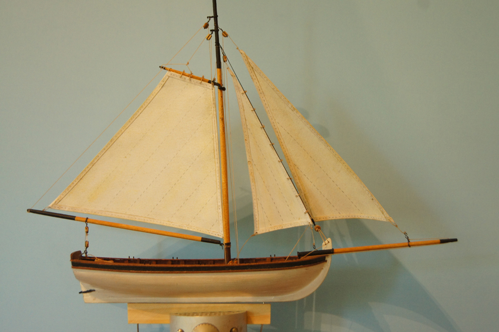
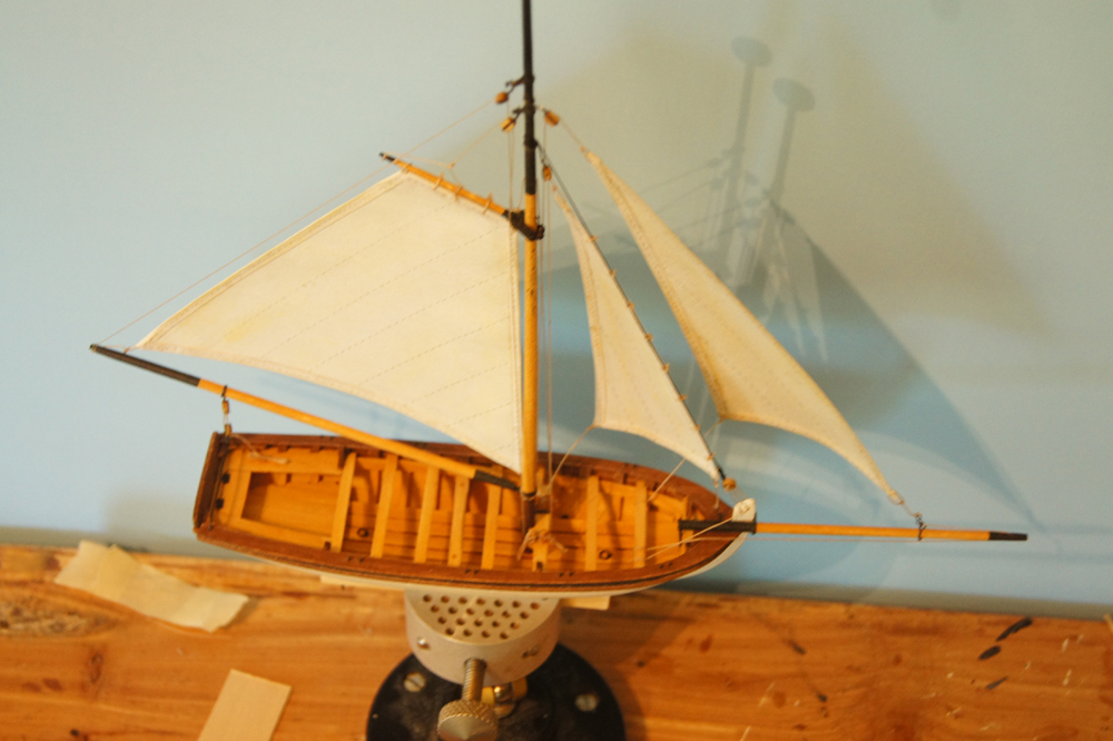
And here she is with the jib. I couldn't find a clear reference for how to shape each sail, so I defaulted to the size & shape they've have if they hung limp within the rigging (as shown on my drawings). I don't know if the jib is actually supposed to be larger than the stay sail, but correct or not, I'm pleased with the outcome from a visual display perspective. The jib is hooked to the bowsprit traveller, allowing it to be hauled out, with a halyard run through a block on the mast just like the stay sail. Seems like it would work in real life. Now it's on to the standing rigging.
- 64 replies
-
- 10
-
-
- 18th century longboat
- model shipways
- (and 1 more)
-
Glenn, Louis C. Hunter's Steamboats on the Western Rivers discusses to the superior maneuverability of side-wheelers over sternwheelers, in part, by referring to "The ability to stop one of the wheels independently of the other and, on two-engine boats, to run the two paddle wheels in opposite directions..." which implies what you suggest, that wheels can be stopped while in motion but not re-engaged. Also, obviously, Heroine couldn't have run her wheels in opposing fashion unlike later boats, so some of the turning ability is negated. Certainly, this makes mechanical sense to me, I don't see any way you could safely or practically slip that clutch into place while the shaft is turning, especially with water pressure holding the wheel in place. And the implicit reference to single-engine boats strongly implies that this all applies to Heroine, since two-engine boats became the standard not long after her time.
-
Thanks for the nice explanation of that 3D shaping, something I've never done before.
-
The sage is beautiful, but what ship modellers really need is more thyme. Lovely model.
- 170 replies
-
- 4
-
-
- gokstad
- dusek ship kits
- (and 1 more)
-
What's important to understand is that someone saying "I want this awesome thing made out of the best possible components which are all expensive, but I want it to cost a dollar" isn't necessarily insisting that all three of those things be true all the time, they're just telling you that those three things are important to them, just as a market customer is telling me that they care about cost, quality, and growing method. It's not breaking news, but this collection of comments tells us that majority of people here like 17-18th ocean-going ships, they have a budget they feel is appropriate, and they value good materials and instructions. Any given designer may not be able to meet all three goals, but they can make an educated decision about which of them to focus on. Again, this thread asked people what they thought in general, as if I handed out a survey of farmers market shoppers. People giving their ideal ideas to a survey is not the same as people specifically criticizing a given vendor. Consumers that challenge my market prices directly and personally are annoying if they don't try to understand the business model. Consumers who tell a survey that they want organic, affordable, nice-looking produce are just telling me in general what's important to them. Respondents to this thread are, by and large, saying what matters to them in general; they're not saying "X company is too expensive or Y company doesn't make models I like". For example, when I say I want a kit to be $250-$400, I'm saying that's as much as I can possibly justify spending. If the only way to make a kit I'd otherwise like is for it to be $600, then I don't want that kit made for me because I won't be able to buy it no matter how nice it is. That's important information for a manufacturer. I'm not insisting they lose money making me a $600 kit for $400, I'm saying that's my budgetary limit, period. We chose not to grow some things on our farm because we couldn't sell them at a price consumers would accept. I'd like to grow them, but I accept that people won't pay me to do so. They can grow them in their home garden if they want those items, or scratchbuild that model, or just do without if that's what life dictates. Again, don't misinterpret what's being said in this forum.
-
Steamboats and other rivercraft - general discussion
Cathead replied to Cathead's topic in Nautical/Naval History
Great point, Bob. That's been on my travel list ever since Kurt mentioned it to me. It's just far enough away from me to make it difficult.- 281 replies
-
- 2
-
-
- Steamboats
- riverboats
- (and 3 more)
-
People aren't being unreasonable, they're doing exactly what they were asked to do by the topic, sharing what they'd like to see. Most of us don't know anything about the business side of kit development (which is why I tried to ask about it earlier), so how do you expect respondents to magically produce only practical answers? Look, no one understands businesses they aren't engaged in. Among other things, I'm a vegetable farmer, and farmers market customers always want their produce organic, perfect, and cheap. Well, you can't have all three. Organic and perfect, it won't be cheap. Organic and cheap, it's going to have bug damage. Perfect and cheap, it ain't going to be chemical-free. But people who have never grown a vegetable in their life, or even people who have a home garden, have no mental structure for evaluating the actual business of vegetable production. So there's no need to get huffy about modellers saying what they'd "like" to see, especially when that's what was asked for. If we can get a nice explanation from the developers of what actually goes into the business model of kit development, maybe then we can give more "realistic" answers. Until then, just take the feedback here at face value as a narrow sampling of a limited community of dedicated modellers and get what value you can from it.
- 117 replies
-
- 17
-
-
Steamboats and other rivercraft - general discussion
Cathead replied to Cathead's topic in Nautical/Naval History
If you want a specific prototype of a working steamboat, look into Bertrand or Cairo. Cairo's frame is on display in Vicksburg, Bertrand has a nice museum and very thorough archeological documentation of its structure and construction. Both are great examples of non-showboat working boats that have a good story to them. You are also correct that many (most?) American riverboats weren't built with plans. There were dedicated boatyards along the upper Ohio churning out boats, but they generally didn't go by blueprint. They weren't backwoods-built, exactly, more like individual custom-builds on an assembly line. So in some ways the best topics are the boats that have been excavated and studied after the fact, like Bertrand or Arabia or Cairo.- 281 replies
-
- 2
-
-
- Steamboats
- riverboats
- (and 3 more)
-
Steamboats and other rivercraft - general discussion
Cathead replied to Cathead's topic in Nautical/Naval History
Daves, http://www.steamboats.org/modelplans/paddlewheelers.html has a lot of plans offered. I bought the plans for my Far West scratchbuild there and was pleased. The site also has a long list of other resources for research. For Bertrand, I mostly relied on archeological drawings from the National Park Service excavation of the wreck (see my log). I'd purchased a set of private plans, too, but found that they conflicted with the NPS drawings so mostly used the latter.- 281 replies
-
- 3
-
-
- Steamboats
- riverboats
- (and 3 more)
-
That is gorgeous.
-
Wow, I'm jealous. Bertrand had hog trusses, sheer, AND camber to her main & boiler decks. I eliminated the camber on the boiler deck for sanity's sake, but still felt I had to build it in place. I cannot wait to see how your deck drops in. Having the CAD skills is a really nice piece of your toolkit. Good luck, if that's the right phrase!