HOLIDAY DONATION DRIVE - SUPPORT MSW - DO YOUR PART TO KEEP THIS GREAT FORUM GOING! (Only 20 donations so far - C'mon guys!)
×


tartane
-
Posts
127 -
Joined
-
Last visited
Content Type
Profiles
Forums
Gallery
Events
Everything posted by tartane
-
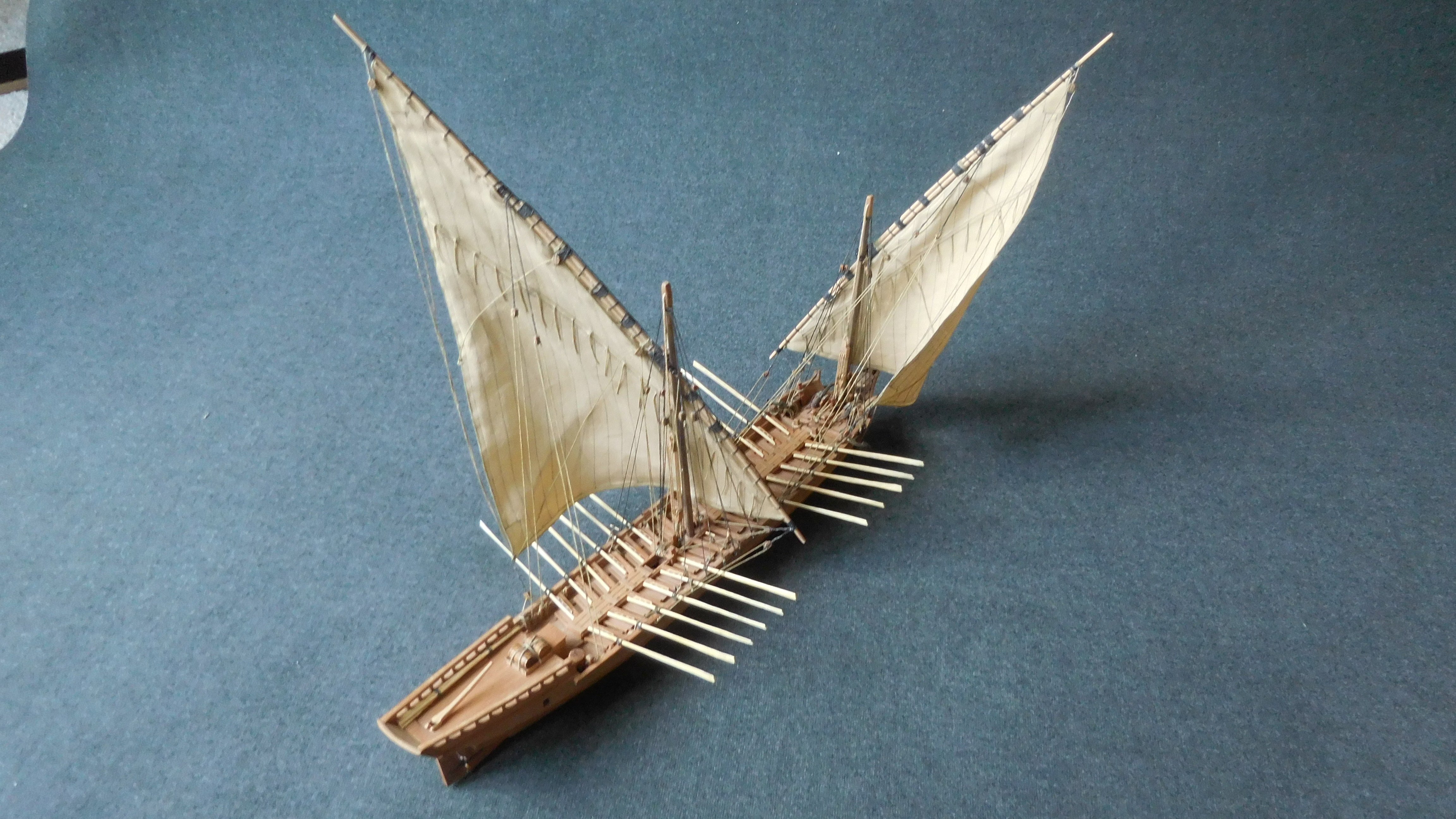
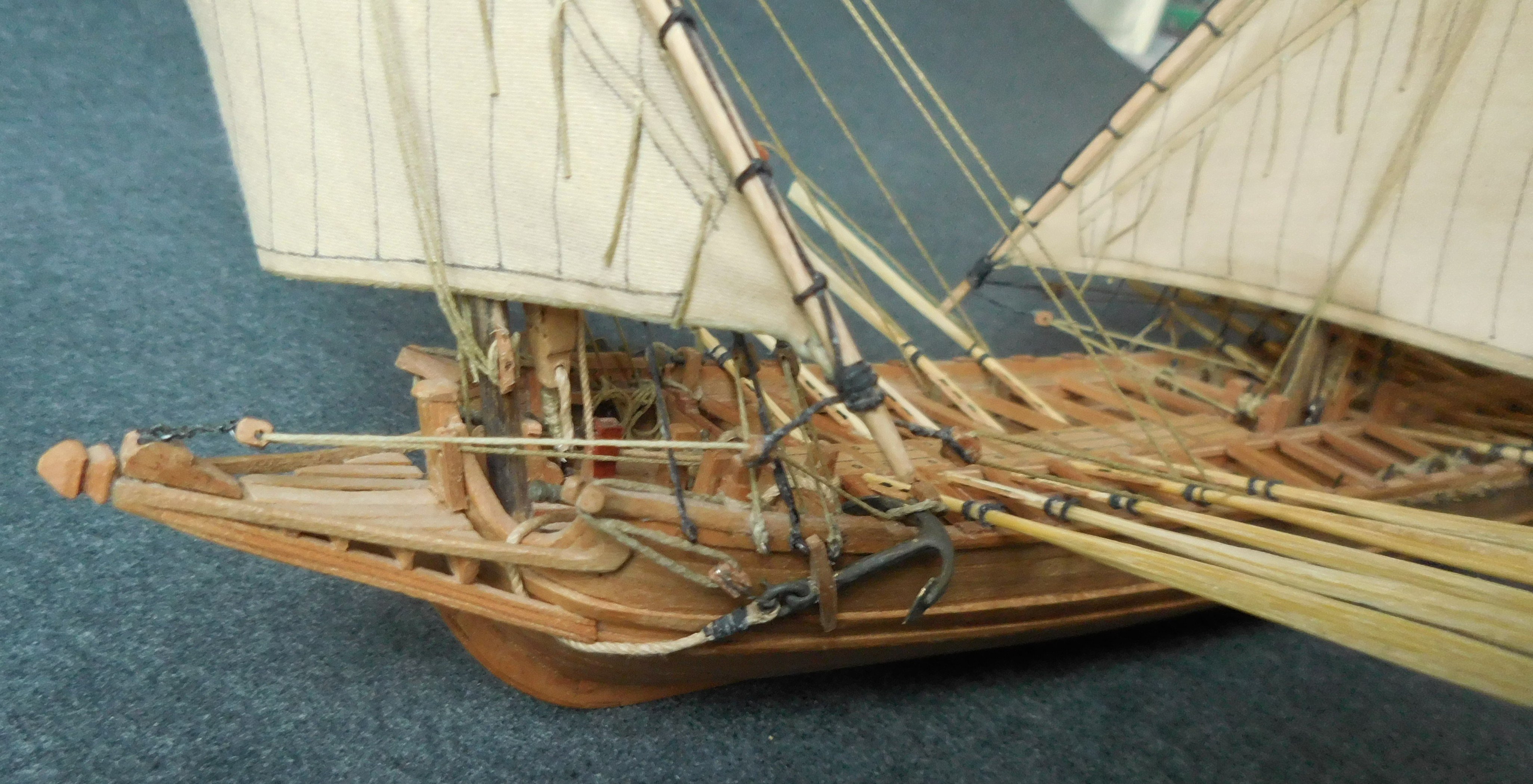
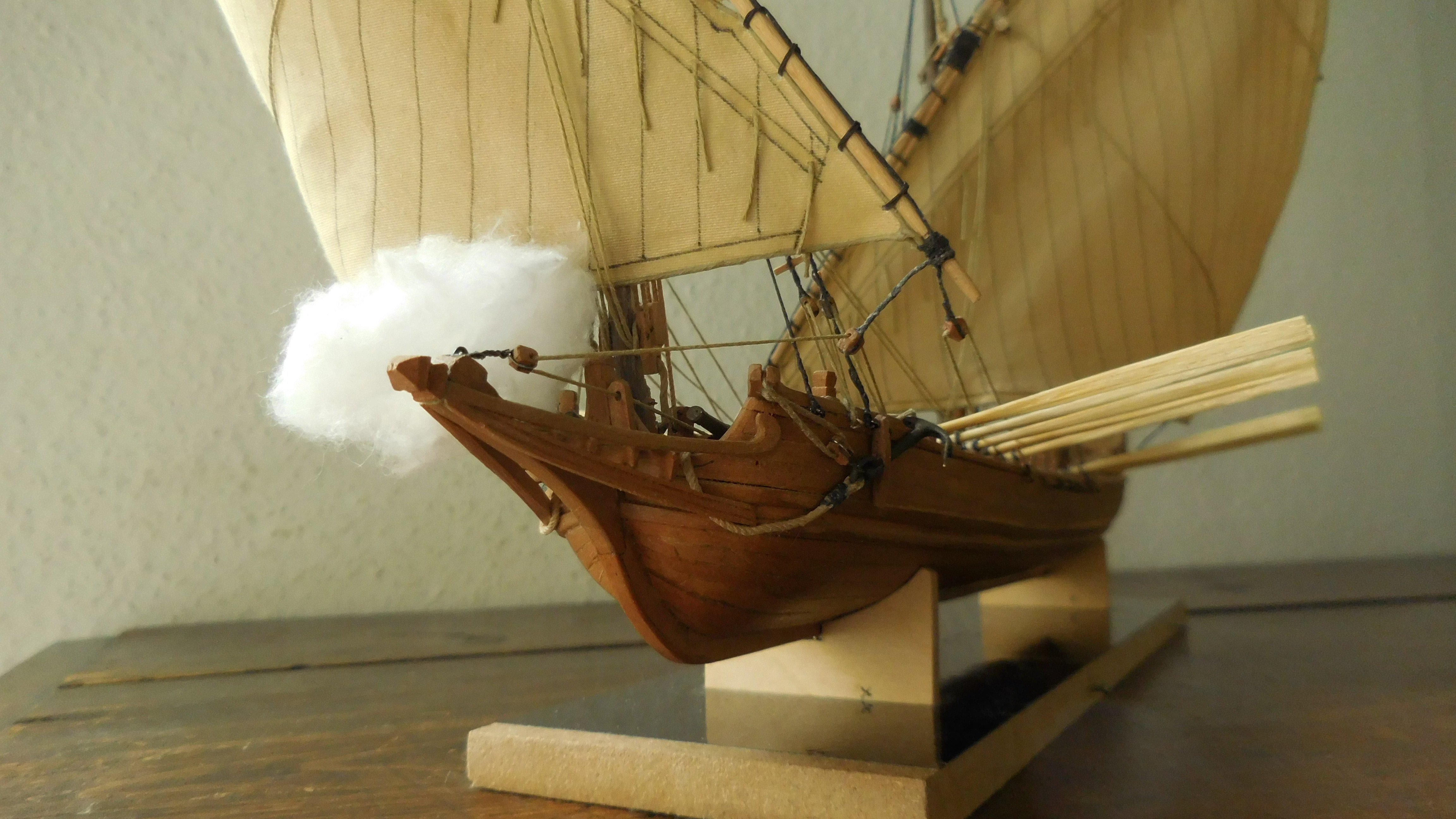
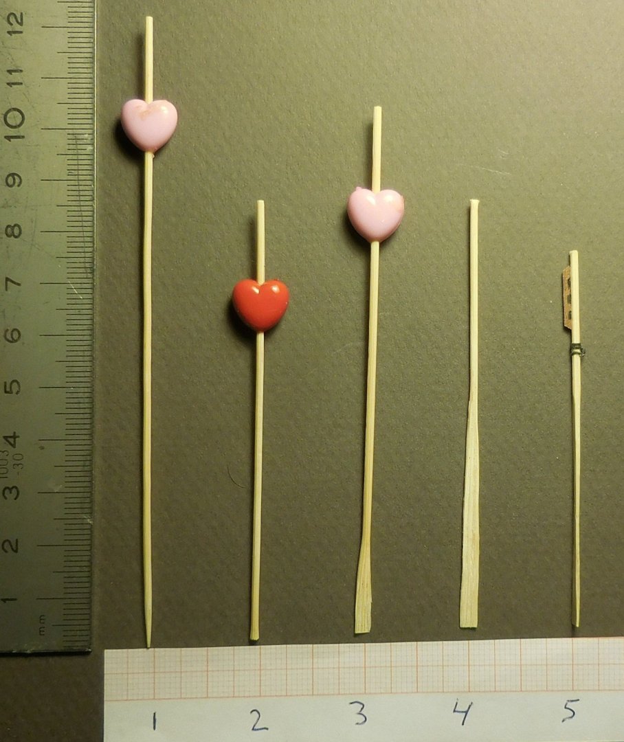
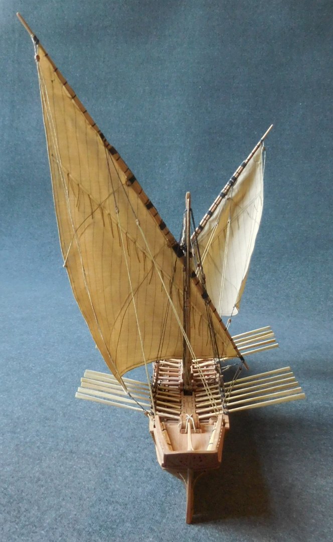
A few years ago I built a model of a Galeotta on a scale of 1:87 (HO) built from pear wood. This model required a number of oars of small size. I made them out of thin cocktail sticks. I carefully hammered out the ends of those sticks with the addition of highly diluted wood glue. After drying, sometimes a few more times. See the photo. 1 cocktail stick of 1 mm thick 2 removed the tip 3 the end flattened with a hammer and provided with diluted wood glue 4 Further hammering made the blade longer and could then be cut into the right shape. 5 Fitting the oars with the handles The oars attached to the fuselage. The ship with full sails and the oars up Constant


-
I do not know if Dutch kids better behave then American kids, but that is the risk one has to take who build a Cannon. Constant
-
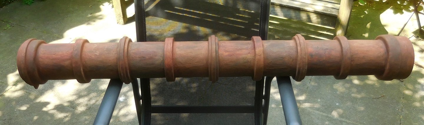
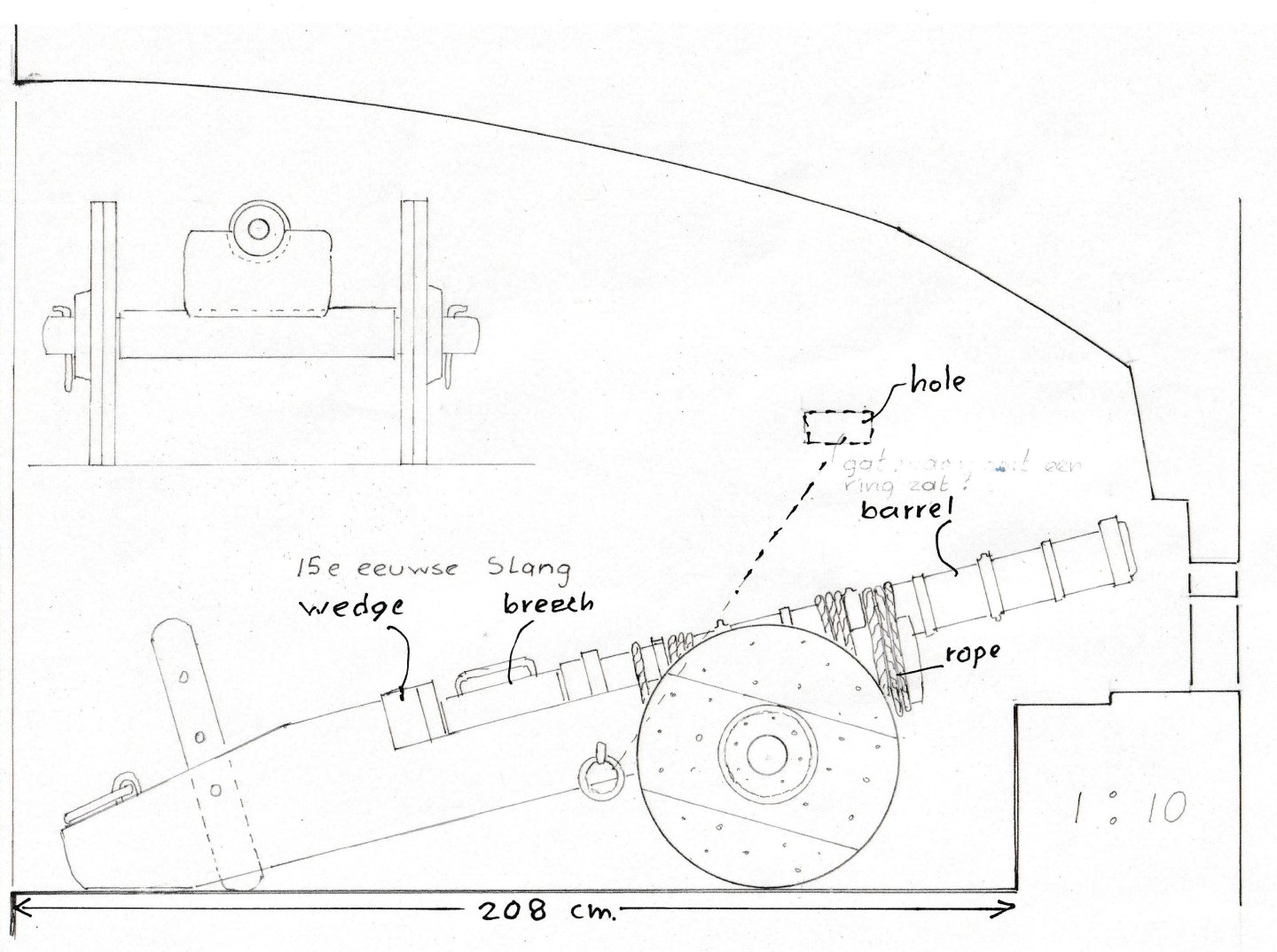
3 After all surfaces were treated, the barrel looked like the photo. The length is 120 cm. The painting was done with two shades of brown and black to get a weathered rusty surface. The inside of the barrel still needs to be made matt black. The mouth of the barrel is a bit rounder, as the examples often show. The breech has to be slid into the back. The breech during the assembly of the parts. Which was entirely according to the method of the barrel. The breech ready to be painted. In the Dutch language, a breech was called a "snelleke". It resembled a beer mug in appearance and the medieval name of a beer mug was "snelleke". In reality, this barrel would have weighed 95 kg but now only 40 kg. This is the situation on this day. It will take somewhat longer before I can show you more Constant


- 23 replies
-
- 13
-

-
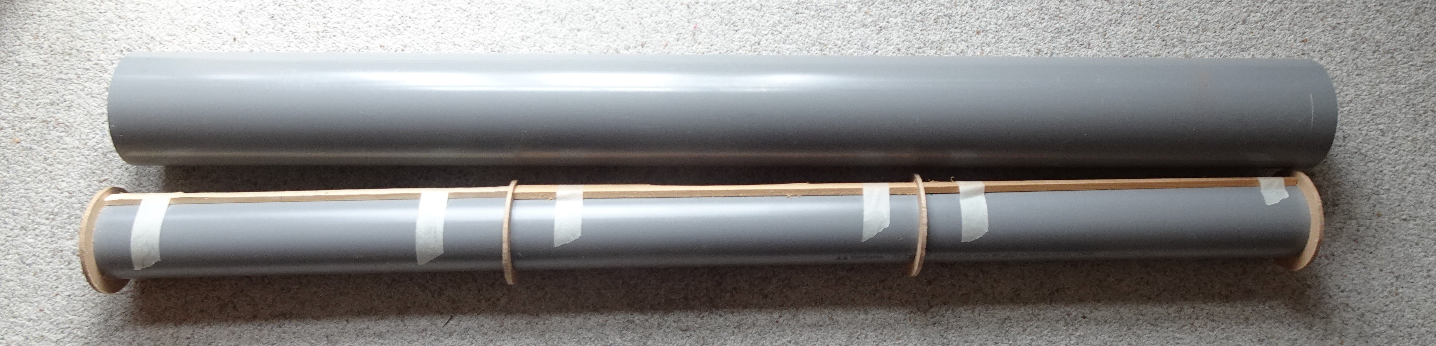
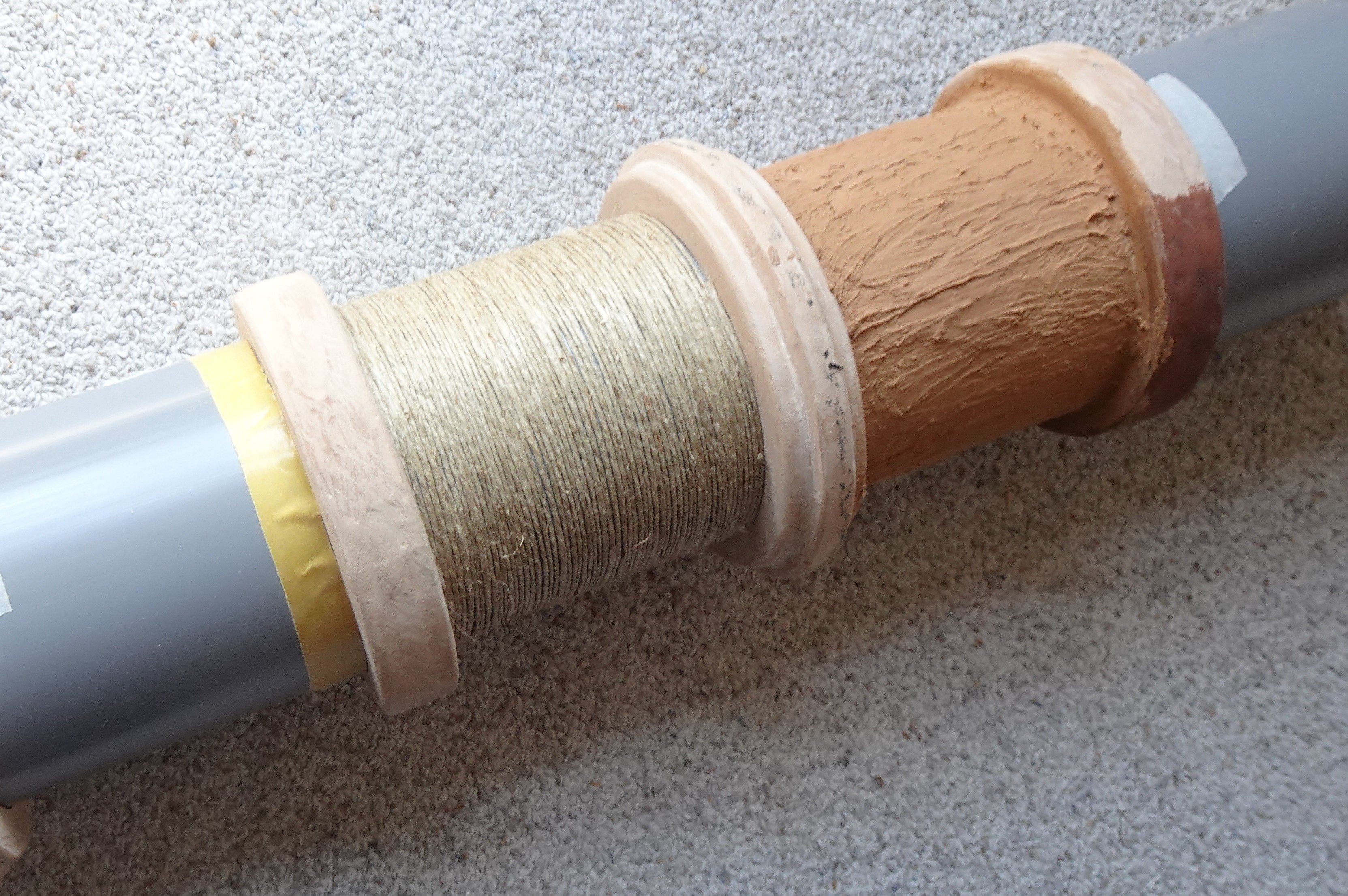
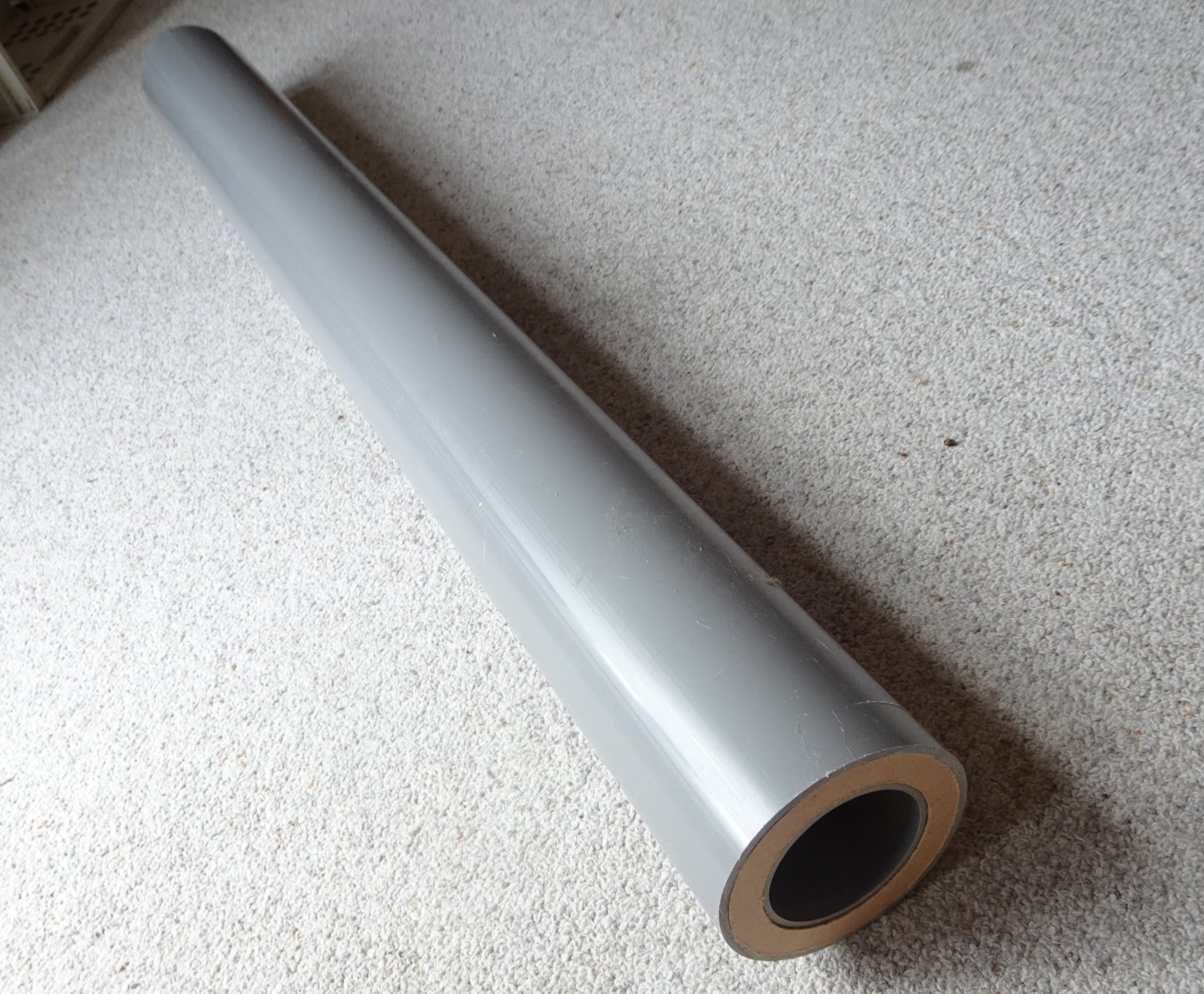
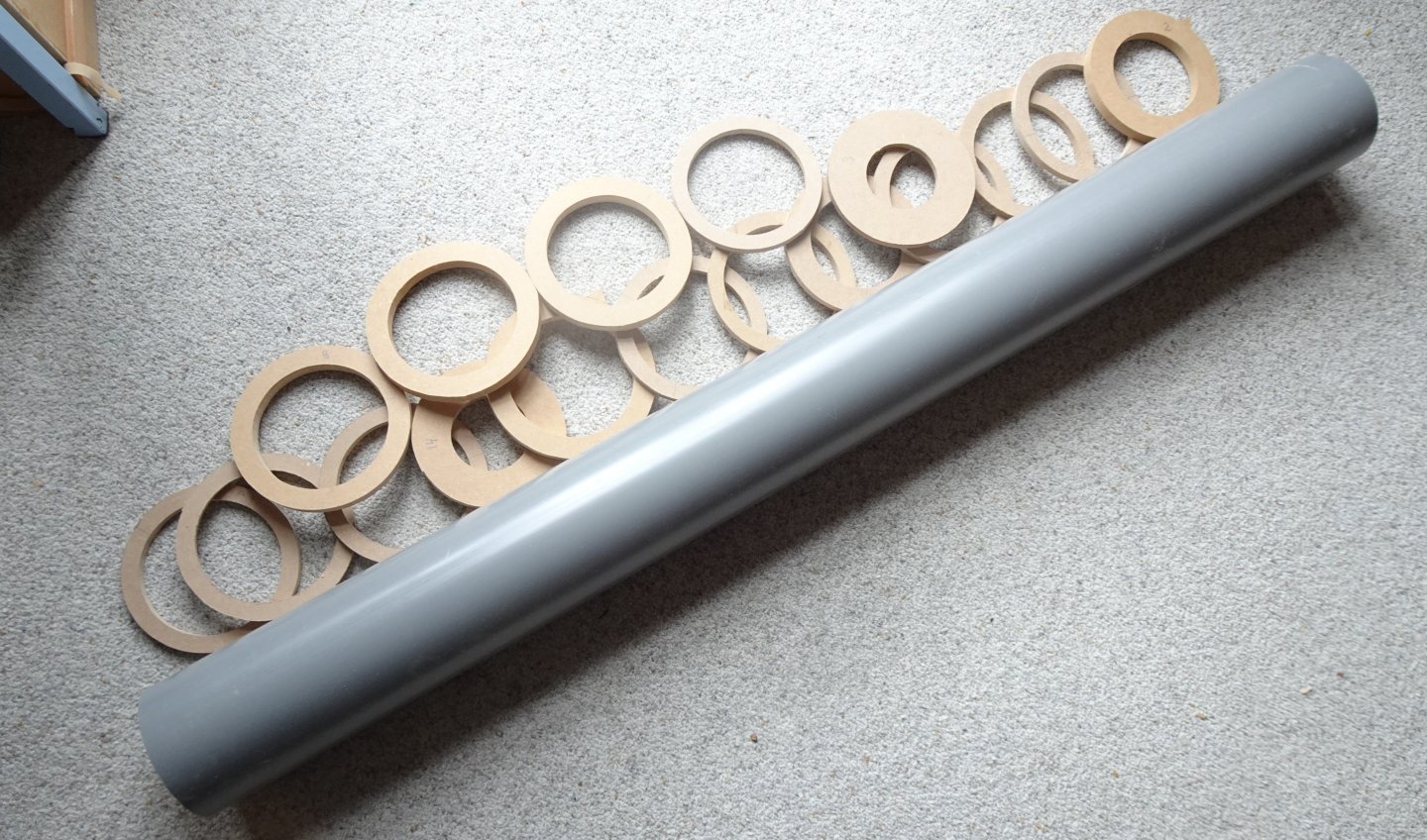
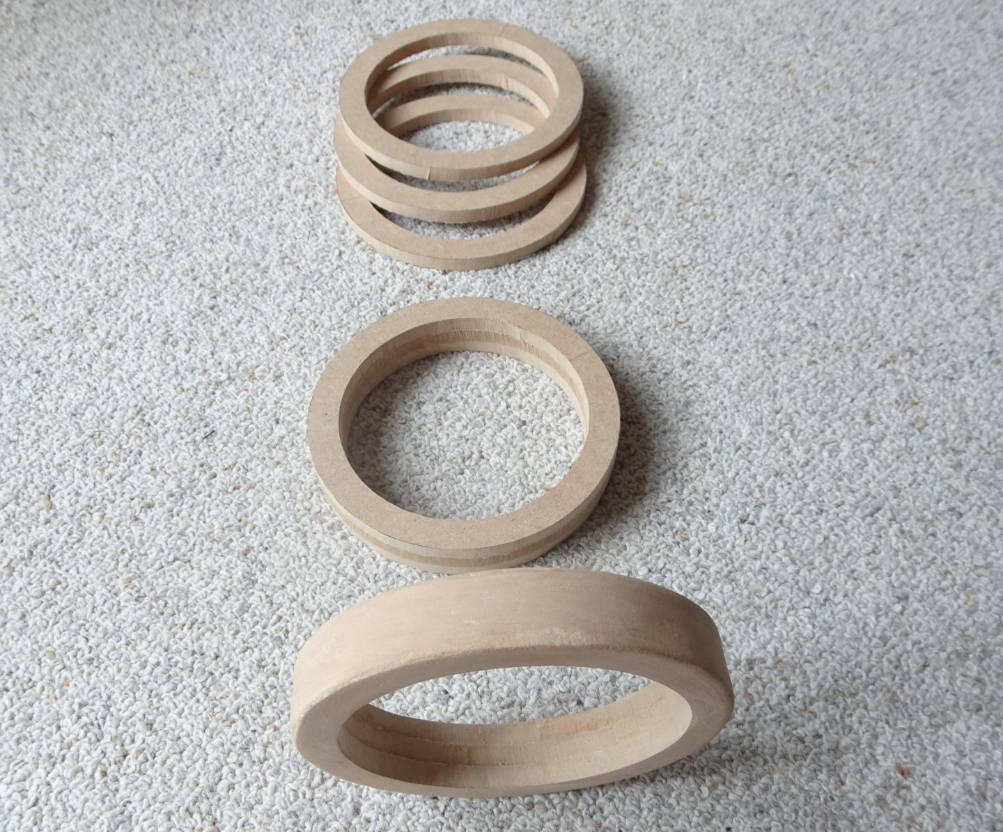
2 The barrel was originally manufactured from long, flat hammered iron bars girded by hoops, the normal way to make gun barrels at the time. The rather small embrasure with a diameter of 200 mm had to be able to allow the barrel with the forged rings to pass through. Existing barrels show that these rings were often only 20 mm thick. I applied this here and so the tube couldn't be much thicker than 110 mm. This results in the internal diameter of the barrel, the caliber. I ended up with 70 mm, after comparing it with existing barrels. All those measurements are approximate, and the barrel had to be made according them. I made the barrel from two PVC sewer pipes, which had the required diameters, namely 115 mm and 75 mm (with an internal size of 68 mm) Pushed together, the outer circumference and the inner diameter provided the required dimensions. The two PVC pipes with spacers around the inner tube. The two tubes pushed together A total of 38 rings of MDF had to be cut out in thicknesses of 8 and 12 mm. I did that manually with the fret- saw. At least three rings glued together now formed a ring. Those rings were slid around the tube in the right places and secured with superglue. The course between the rings was now much too slippery. We agreed that the barrel would have the appearance of an excavated barrel and would therefore be heavily rusted and rusted in here and there. So the slipperiness had to disappear. Around the tube, between the rings, there was first double-sided tape. Very tight thin rope was wound over it, without gaps in between, on the left of the photo. I needed about 145 meter. Then a thin layer of liquid MDF was smeared on top of it, on the right side of the photo. After which it became a rough surface after drying. That surface was filed and trimmed again until a lumpy surface was created, which was then painted in a rust color. The MDF rings were also smeared with liquid MDF at the same time as the gaps. In this way, it became a unity.

- 23 replies
-
- 10
-
-
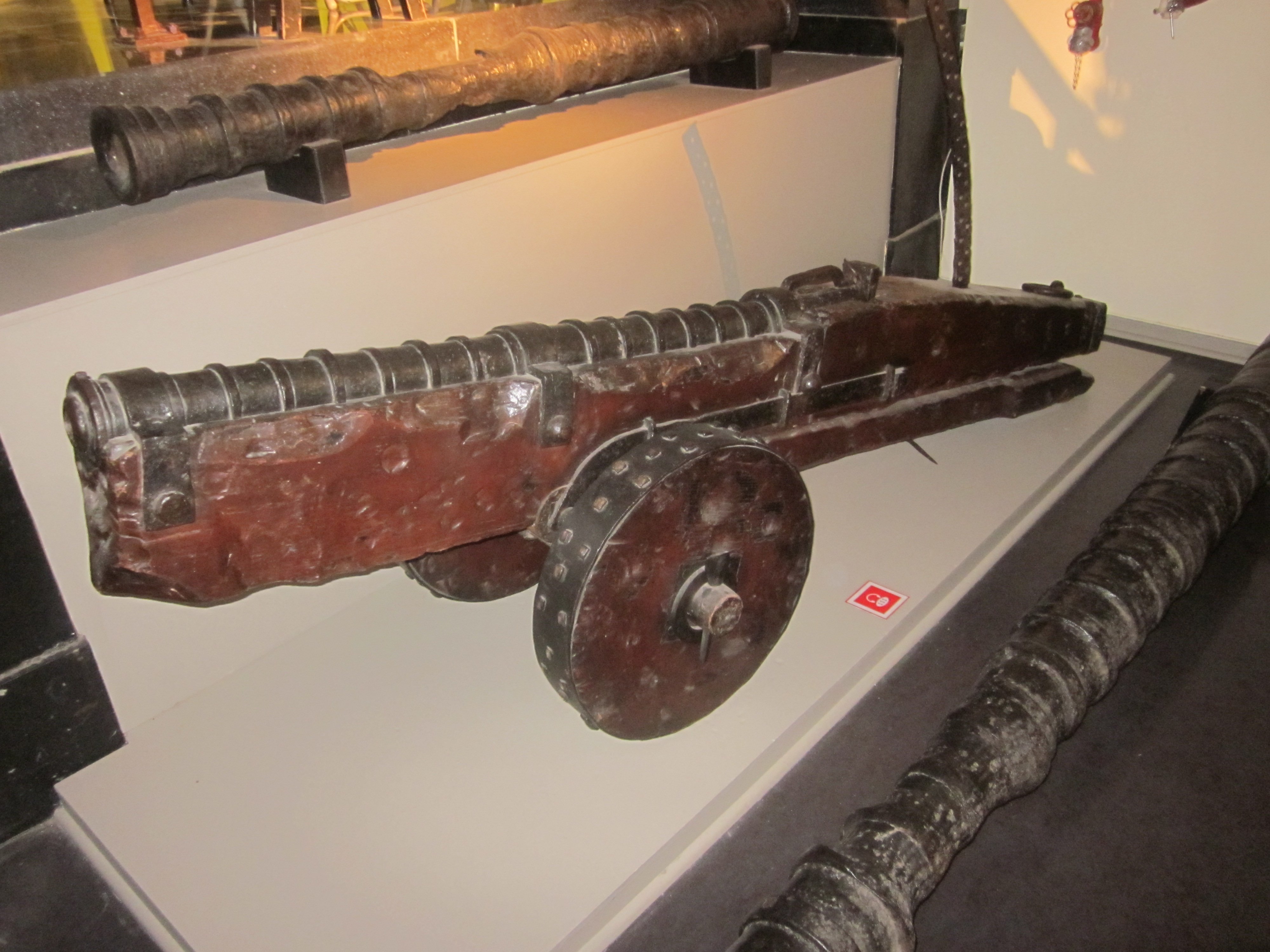
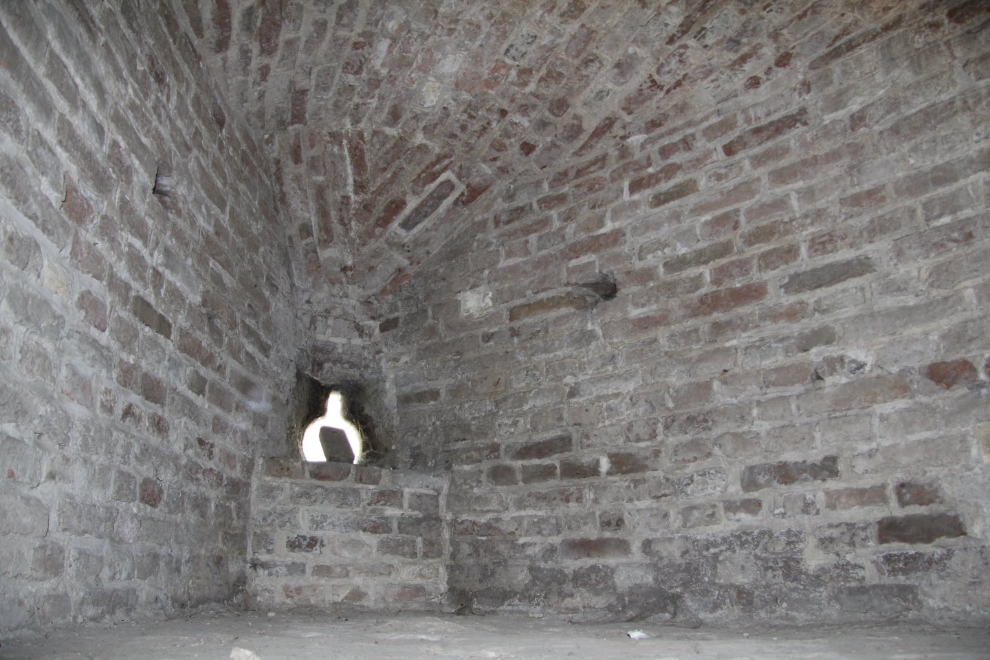
Something went wrong, these words belong to the former message A photo of the niche in which such a cannon stood. In the background the loophole with a short slit above it. A photo of such a cannon in the National Military Museum in the Netherlands. Constant

- 23 replies
-
- 12
-
-
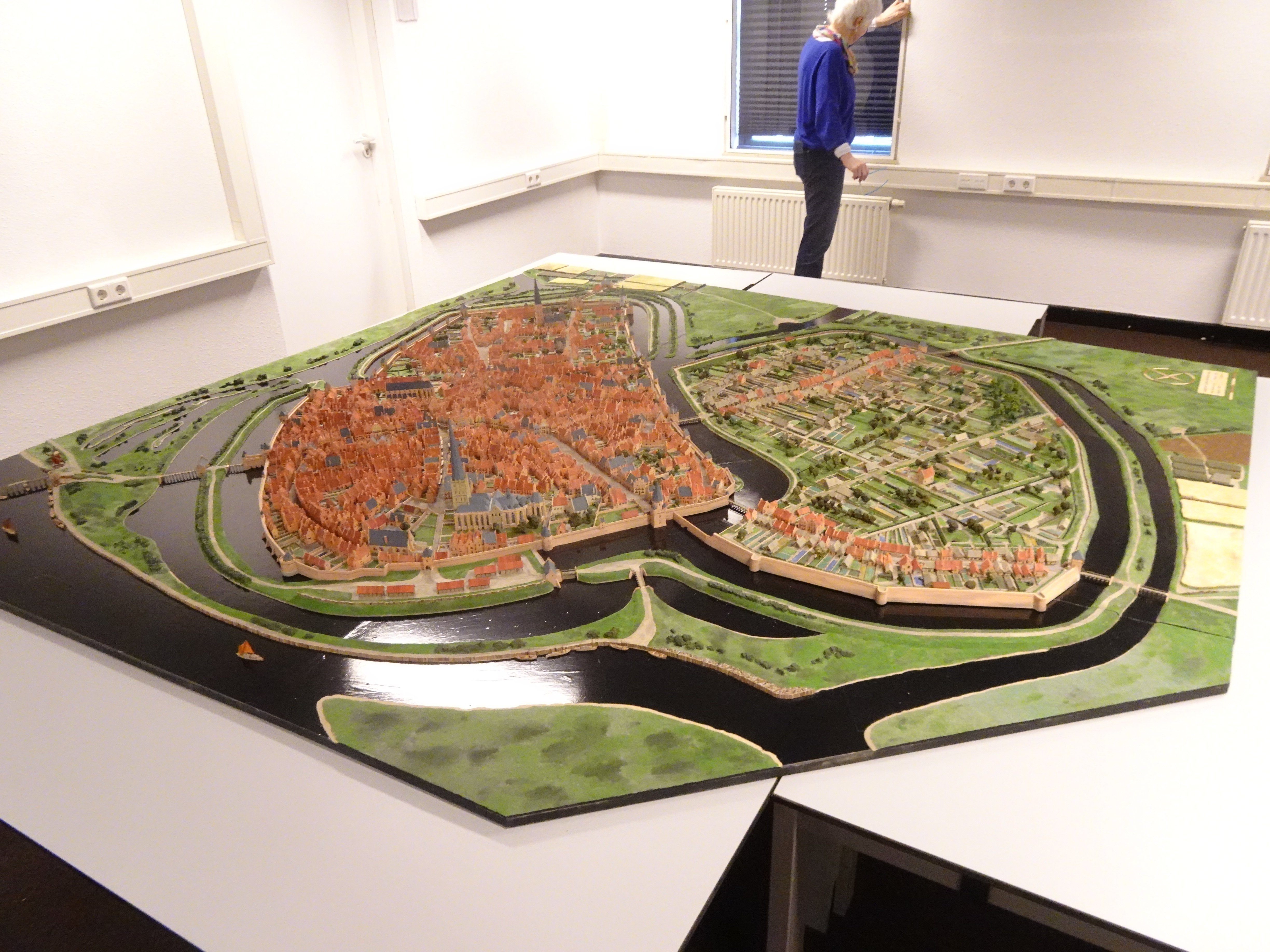
A 15th century cannon as found on the Mary Rose. Scale 1 : 1. Construction, description and research. 1 As some of you will know, I have built a model of the city of Zutphen, where I live, as the city looked like in 1485. It took me five years to build on it and, together with two other people, I also did the long-term research. The construction took 6500 hours and the result is a large model on a scale of 1:500 which also gave us a lot of the history of the city. This model will be given a permanent place in a heavy artillery tower from 1457. A tower with a wall thickness of 4 meters, the Burgundy Tower. The interior of the tower is currently being modified to accommodate the model. In this way, a new museum is being created around the model. There have been a number of gun emplacements in the tower. One of those will now house a full-size replica of a 15th century cannon. This also required a lot of research. Good examples were found in museums in the Netherlands and especially in England. We also looked at the various cannons of the Mary Rose. Obviously, there was no standardization in such artillery. Each cannon was different, but all according to the same principle. I started building that cannon and made drawings in advance. From accounts of the city around about 1450 we know that they were ordered and also what they looked like. They were referred to there as “ Slang” (snake), the name that the replica will also be given. Afterwards, especially after 1500, these cannons were referred to as culverein. But we are not going to use that name because of the specific name in the Zutphen archives. First, the drawing of the cannon in its entirety. The black lines all around are the exact dimensions of the existing gun emplacement from 1457. Within that, I had to stick to the dimensions. The embrasure is round with a diameter of 20 cm. So the barrel had to be able to pass through that. As a result, the caliber of the barrel was also roughly fixed. It looks like one of the cannons of the Mary Rose, but smaller. It should be clear that the cannon may have looked different, but the working method, the caliber, the construction of the gun carriage and the use of stone balls are certain. It is mainly intended to give visitors an idea about a cannon from the 15th century. A photo of the niche in which such a cannon stood. In the background the loophole with a short slit above it. A photo of such a cannon in the National Military Museum in the Netherlands. Constant

- 23 replies
-
- 14
-

-
-
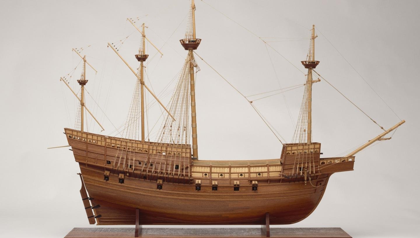
Thank you for your explanation, I didn't know that about the guns and didn't find it in the information I can find. I continue to follow the construction of your model with interest, you do that with a lot of craftsmanship, and also come across the problems I had when building my models, and did research on that (but with someone else I'm probably a bit too enthusiastic) In the meantime I also see that the model in Greenich is not correct, the gun ports are not in the right places, according to the excavations. Good luck with the build! Constant
-
I do not understand what is wrong with talking about shipbuilding. I thought this forum was meant to help each other and create interesting things together. But if the intention is to ban me from this forum and accuse me of inproper behavior please let me know Constant
-
If you study the excavated guns of the Mary Rose, it becomes clear that the heaviest guns had large dimensions. The heaviest guns were also front loaders and they were placed as low as possible in the ship. To operate such a cannon, a space of at least 80 cm was needed between the mouth of the barrel and the ship's hull. This space is needed to clean the barrel after a shot and to be able to put the bullet and powder in. Then came the cannon itself, of which I don't know the exact length and then there had to be a space behind the cannon to give space to the hoists that had to hold the cannon while loading. On the other side of the ship, exactly the same thing happened. So there had to be as few obstacles as possible in between. You can see on many warships that there were no cannons at the position of the masts. On the MR, the spaces between the gunports are not evenly distributed. It is therefore very likely that the masts were located in the middle of the greatest distances between the gunports. If you know the length of the guns, in this case the length of the barrel, you can calculate the minimum width of the ship. Warships had to be able to sail fast, so the width of the ship was kept as narrow as possible. You might find this useful. Constant
-
Is anything known about the exact position of the masts on the ship? It doesn't seem to be because only one side of the ship has been recovered. Based on the locations of the gun ports, it is possible to see exactly where the masts stood. Constant
-
Can this reconstruction contribute anything to the bow of the Mary Rose? It is in the Mary Rose Museum in Greenwich. Constant
-
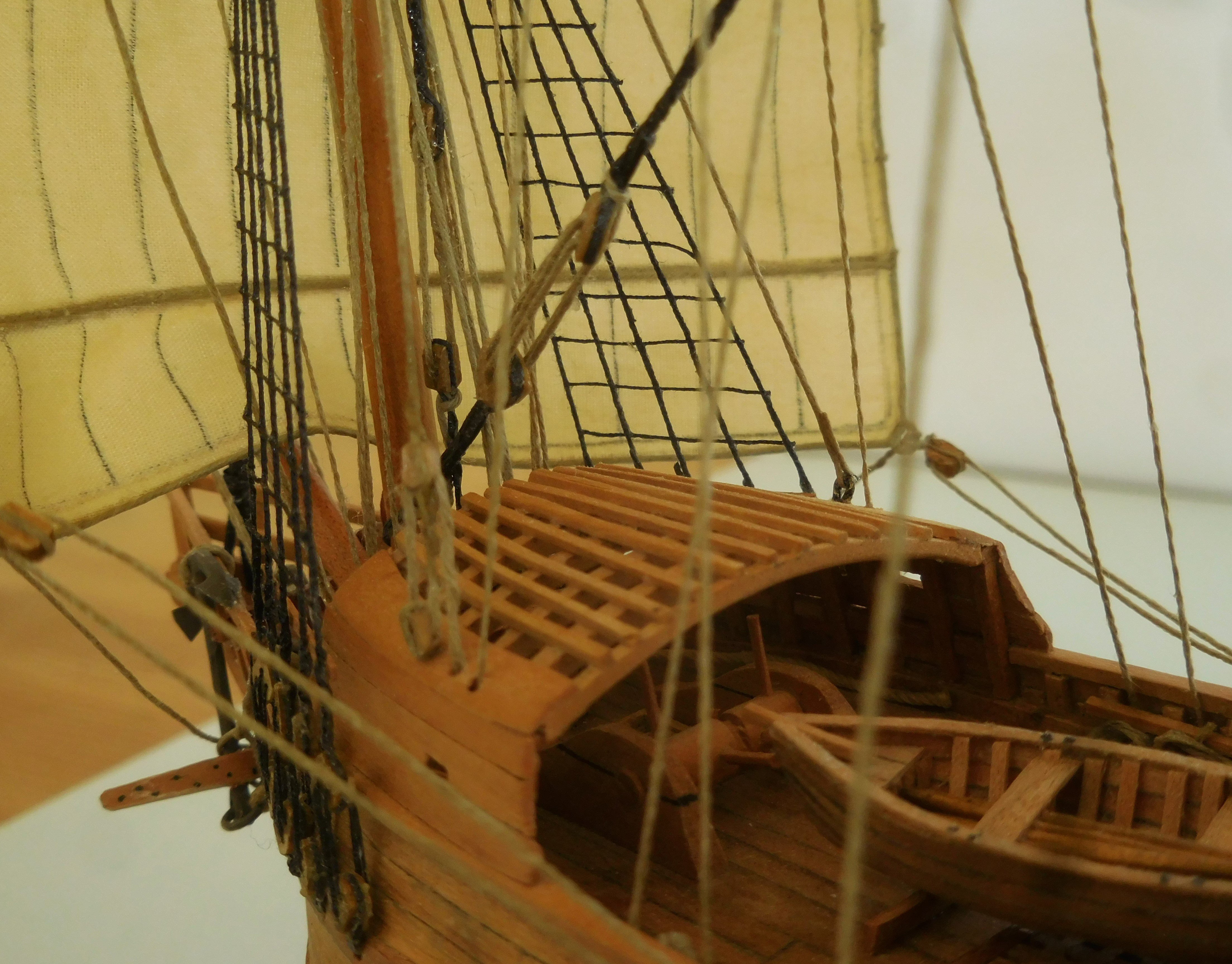
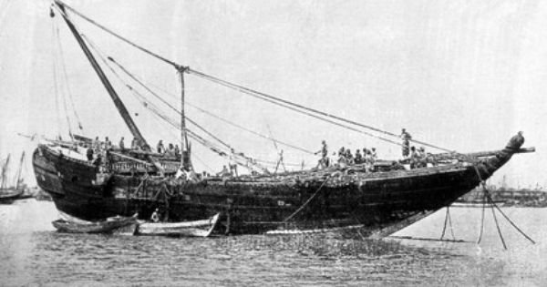
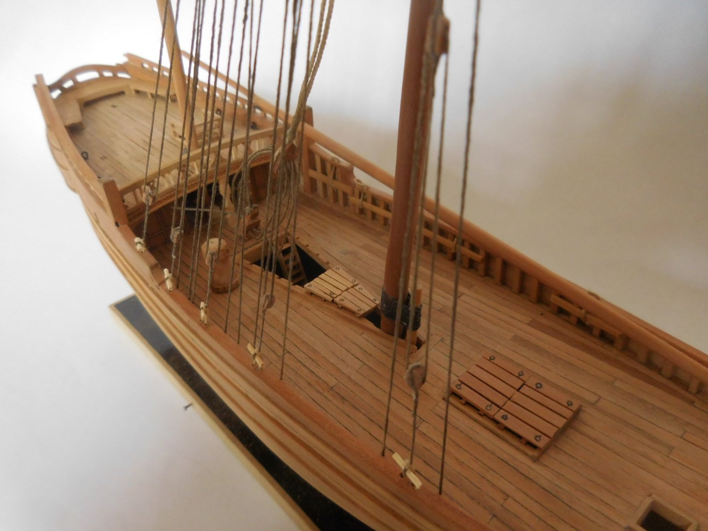
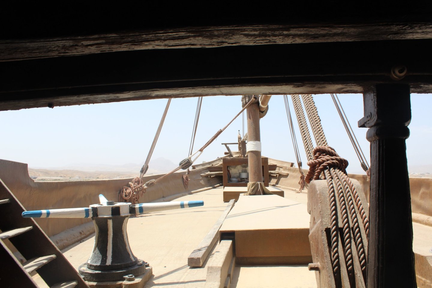
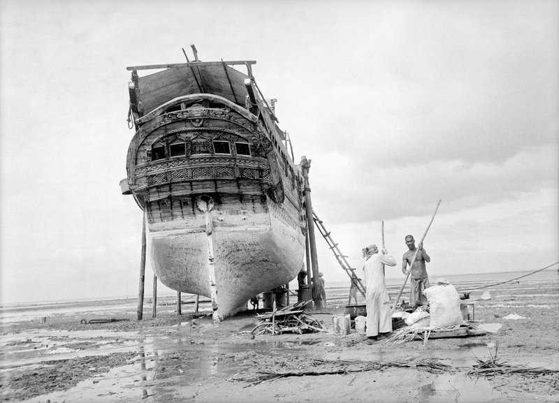
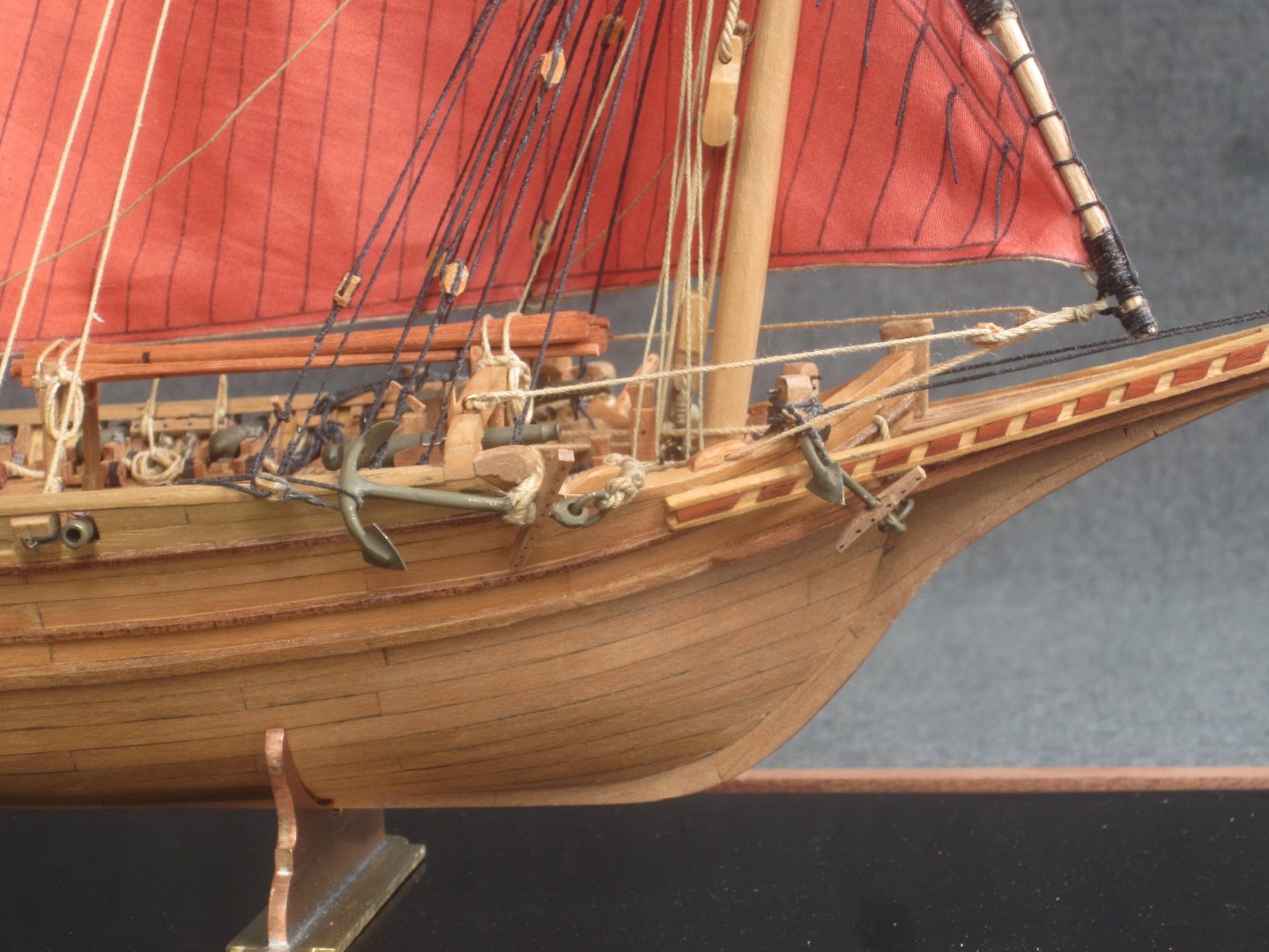
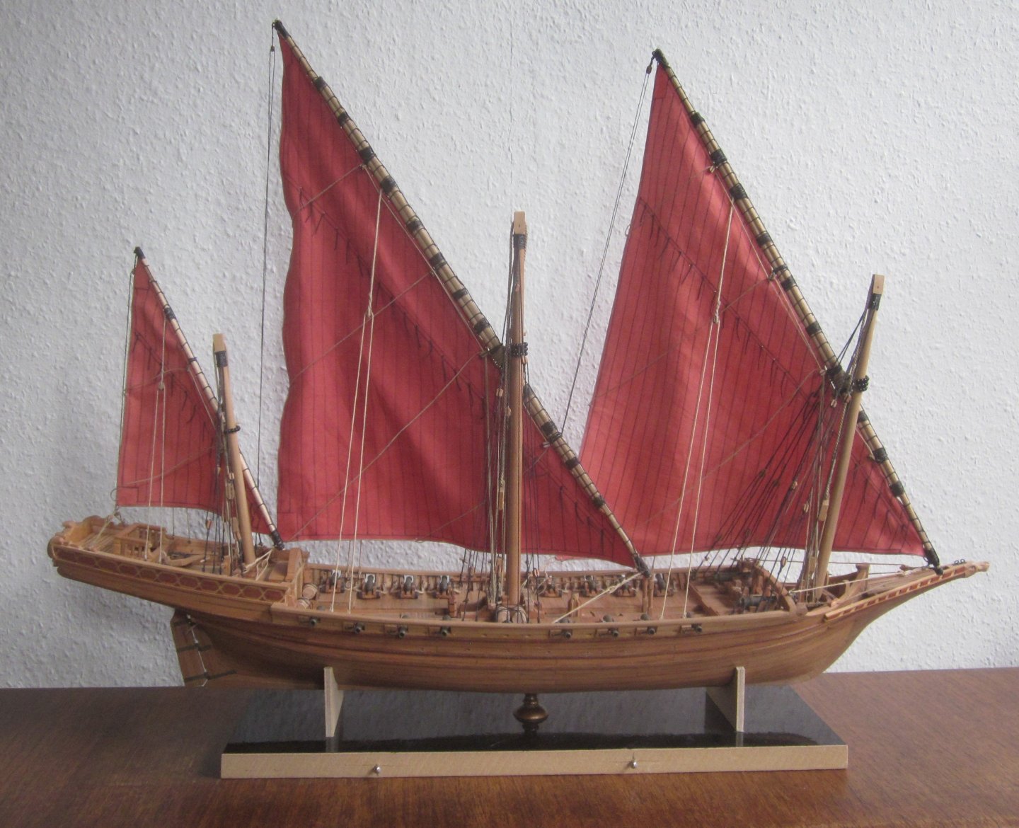
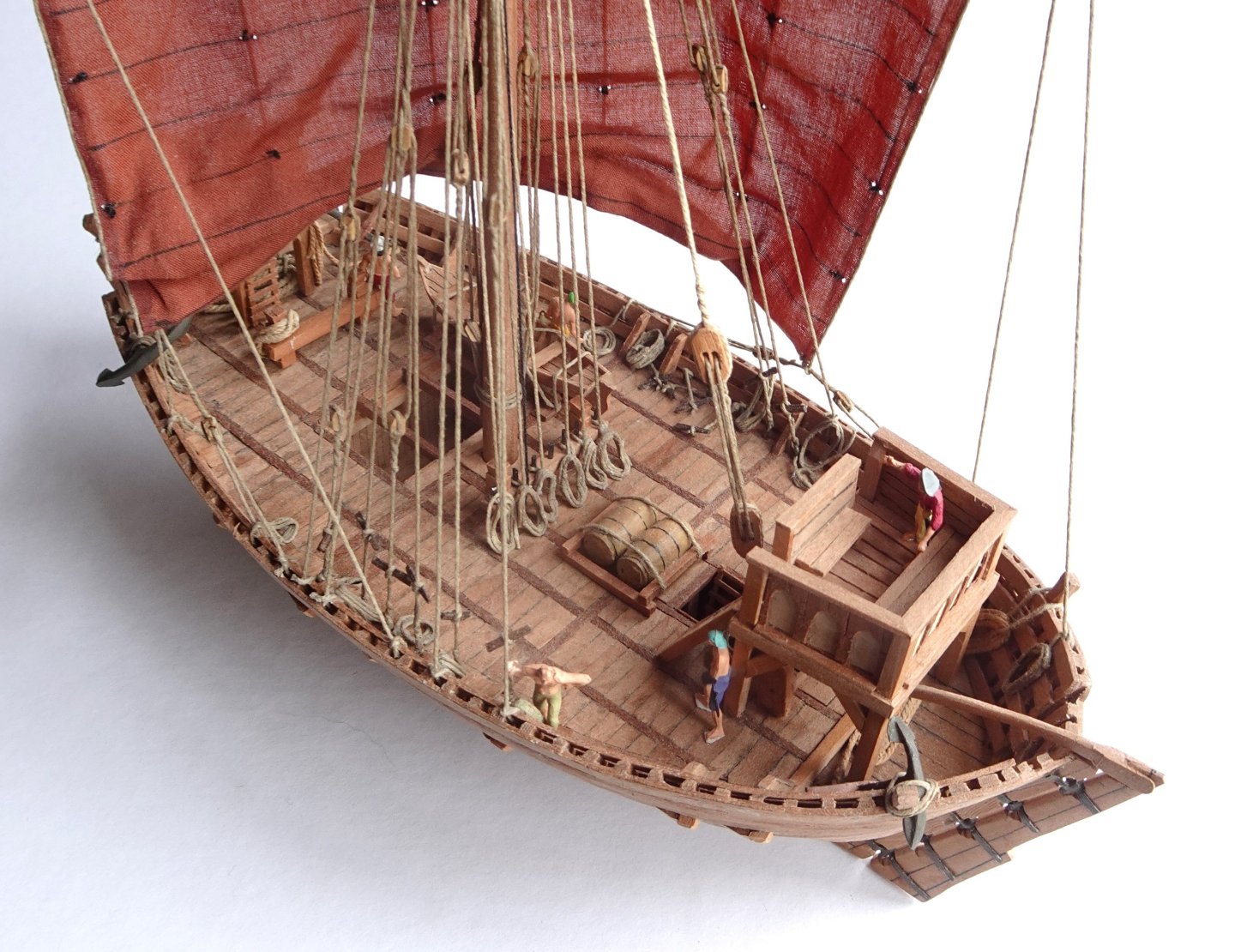
Steven I understand that you want to continue building and that this discussion hinders you in the construction of your model. Finally, I would like to state one thing to complete the story. You came up with the photos of a Ghanjah, noting that the halyard went backwards at an angle and could therefore interfere with the latin sail of the aft mast. With a Ghanjah, and with several types in the extended family of Dhows, it is customary that when the ship is on the beach for maintenance, the mainmast is lowered. It then falls backwards into a trench that was kept free for this purpose. As a result, it is impossible to attach the halyard to the base of the mast, and the halyard must be attached further back. In the accompanying pictures you can see a Ghanjah, or a Baghla, or a Kotia, these are the three largest types of the family, which has lowered the mast to the rear. In the picture of the deck you can see that trench in front of you, covered by a plank, before the mast, so without facilities for hoisting the rod, that was not possible. You can also see the capstan on the side, to give space for the mast. I think the crew takes it for granted that the latin sail of the aft mast sometimes gives problems when tacking, which is caused by the possibility of tilting the mast. I wish you success in the further construction and I will follow you with interest. Constant
-
Most of the pictures you show are fanciful representations of something an artist saw. I can't clearly distinguish the halyards anywhere and mainly see the shrouds. The photos are clear. These are Ghanjahs sailing east of Africa, and they still look as they did when they were designed in the nineteenth century. The youngest were built around 1955 and are still sailing. There you can indeed see the halyards far back, but because this is a ship with two masts, the aft sail was much smaller mainly used to steer more than to provide propulsion. As a result, the sail is also much more manoeuvrable and can be guided over a halyard. In ships with three masts, it is certainly the case that all three sails are used for propulsion, and they are about the same size and then a halyard guided backwards gets in the way. But above all….., you have to make it the way you see it. But may I conclude from this that you are going to use Latin sails? That is not entirely clear to me yet. Constant
-
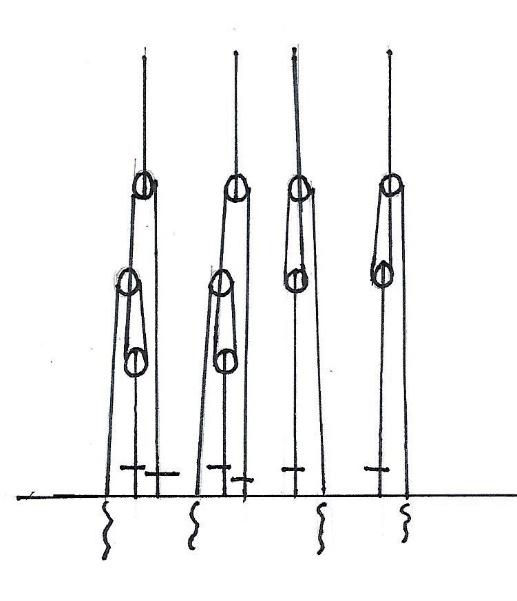
The shrouds are pulled tight by a number of blocks. On a few of my models, I've used all four. Depending on the wind direction, a few are sometimes not used if the sail is broken in such a way that it would rub against the shrouds. The shrouds that are left out are then attached to the leeside. See the drawing On port side are all four shrouds in use, on starboard only two. Because of the blocks these are easy to handle. Constant

-
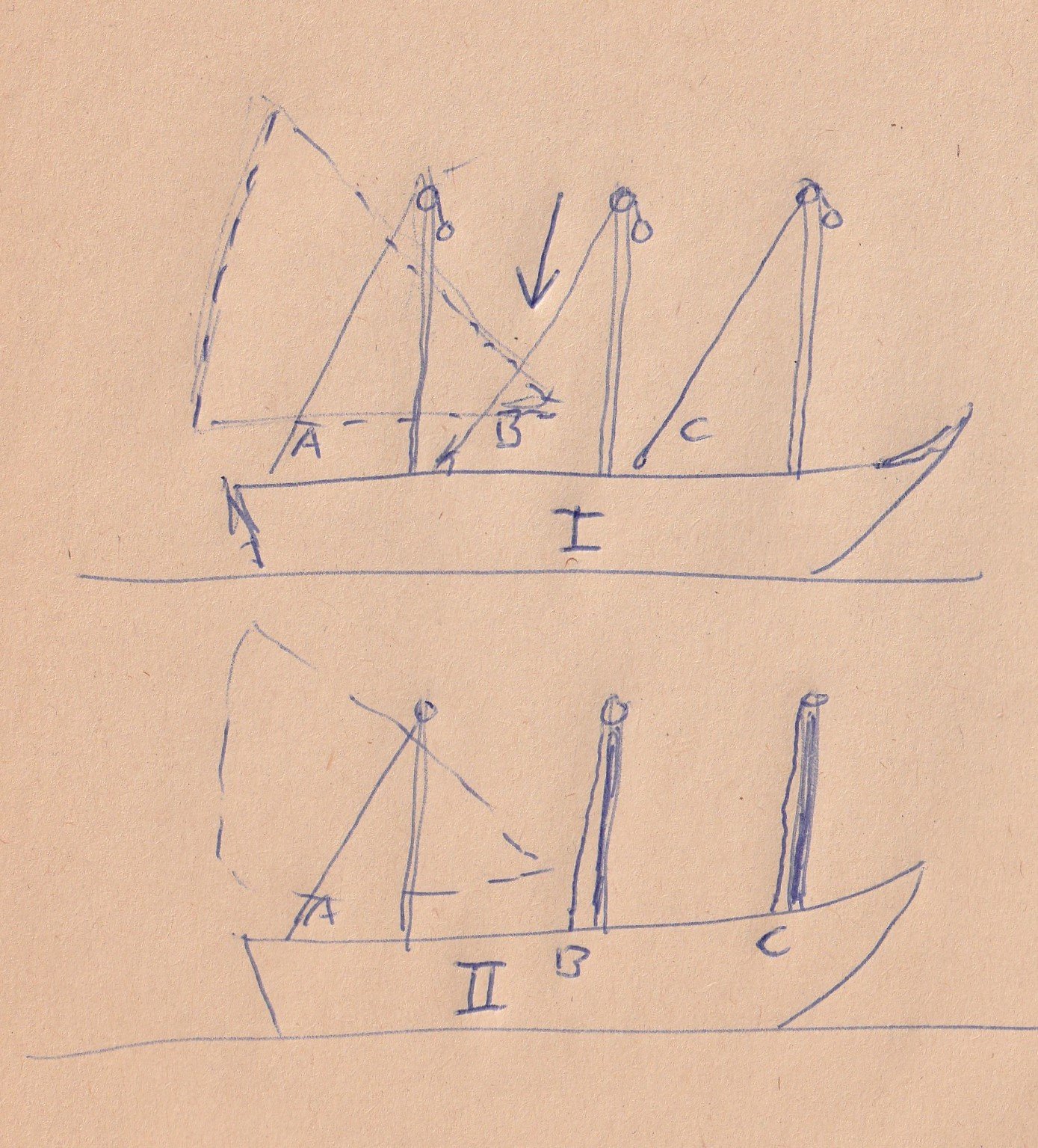
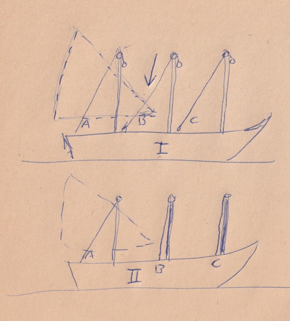
Steven It's good to see that you're moving forward with your building instructions. After all the discussions, I thought it better to stop doing that so as not to block your story about the construction of the model, also because you didn't respond to the discussion. But fortunately, it has all remained understandable and you are now building again. I wonder what kind of rigging is going to be on it now, I can't quite follow that in your comment. If you are going to follow the latin rigging, there are a few parts of the rig that you have made which stand in the way. I mean the halyards needed to hoist the rod. The way you make it, this can only be done at the aft mast. See the sketch number I. Halyard A can sit well but the halyards B and C will collide with the rod of the aft mast and the rod of the middle mast. On sketch II you can see how it could be done, the halyards are then attached directly behind the masts. If you're going to rig the model square, it doesn't matter. I'm showing two more pictures of a chebec that I built where you can see that the halyard goes along the mast and is attached behind the mast foot. You're building a beautiful ship! Constant
-
Christiano, Thanks for all the explanations about the ships in the mediterranean. For a long time I have been researching the historical development of the chebec. Its origins, the early chebece, the later chebec and the chebec that was recreated by the French navy. As a result, I build models of Latin-rigged ships. There is also a major development in this, which is always about the ship with the same name. So I understand very well the complexity of these types of ships. They were built for trade purposes as well as for war. Ships that also had to do with this were for example the Tartane and the Venetian/Austrian Galeotta , of which I also built models. In this way I have learned a lot about the rigging of these ships and therefore I would like to advise on the construction of such ship models. www.constantwillems.nl I would like to end this conversation because it is no longer about Steve's topic. Constant
-
When I look at the first posting on this subject, Steve writes that the images of the mosaic depict Latin-rigged ships. But there is no doubt at all that they are square-rigged ships depicted on it. I don't see any indication that those sails would be triangular. Later in his story, he also shows images of square-rigged ships. It is on that basis that I expressed my surprise at this in order to prevent him from getting stuck in the rigging of his model. It is only meant to help him. I see it as a mistake and not as ignorance on Steve's part. He builds very accurate. In numerous descriptions and studies of that time, square-rigged ships appear in particular, which also makes sense when you look at the available images. Mainz in Germany is home to the Museum für Antike Schiffahrt. A large magnificent museum with its own research department. Many ship models are set up to scale there, mainly on the basis of excavations all over the world. I have visited it several times but unfortunately you are not allowed to photograph there, otherwise I could show countless good examples of those ships. Almost without exception, these are square-rigged ships. It's a pity that those models aren't depicted on their website either. Iconic images first and foremost show something about the usually religious event that they are meant to depict. The ships that are depicted are only an afterthought, and often not correct. It is all up to Steve what he wants to do with my opinion. Constant
-
I'm going to stop this discussion because I'm not going to talk to anyone who says I'm dead wrong. Now there is no room left to talk about it. The message I sent was for Steven and I would like to hear his opinion. I wish Steven the best of luck with the model. He is building a nice model and I'm looking forward to him managing to make a working latin rig out of it. Constant
-
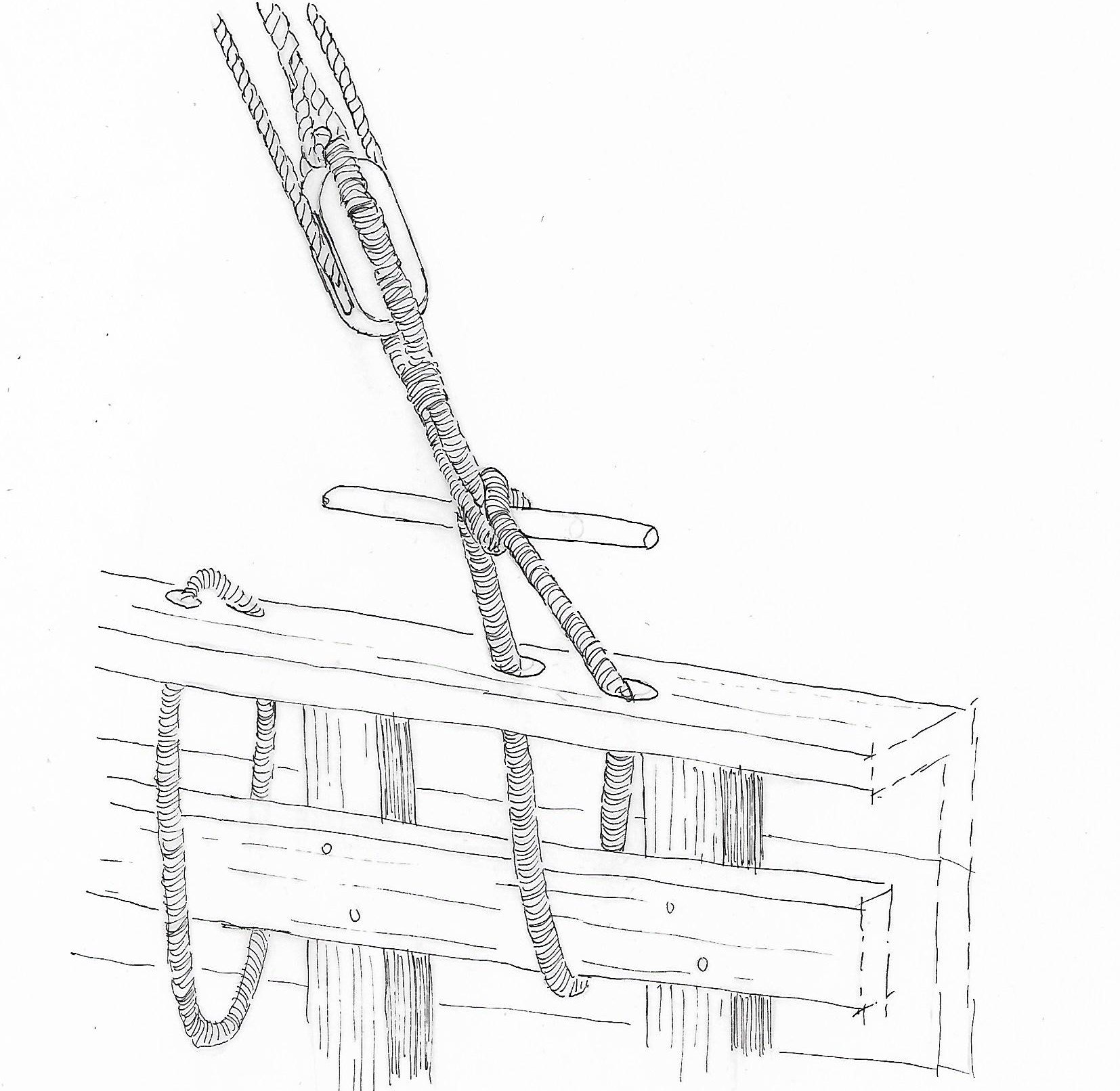
Something went wrong and I had not the opportunity to place a second picture, but here it is. This is a knevel. Constant

-
Steven Why do you make latin sails on your model? In all the images you show from antiquity, I only see square-rigged ships. To make these drawings more vivid, the draughtsmen used sails that were not quite quadrangular, and therefore they look like Latin sails. But they were quadrangular. Ships with latin sails never have crow's nests, which would make it almost impossible to convert the sails to port or starboard. If a latin rigged ship tacks, the rod and sail had to be turned around the front of the mast. That was a major operation in which all the shrouds were removed and all the ropes that were attached to the rod and sails. I have made several Latin-rigged ship models and did a lot of research on them beforehand. Also, latin-rigged ships did not have rope ladders and stays, which also had to do with the conversion of the sails and rods. The rigging of your ship most closely resembles the rigging of a cog. There I would also make so-called Knevels, I don't know the English word. They ensured that the shrouds could be removed quickly. By brassing the sails, cogs could sail quite sharply to the wind, and that is also the case with your model, for that you needed those knevels. I'll show you a picture of a cog I built from 1240, there you can see the knevels and also that the shrouds on the leeward side (here starboard) have been loosened for half, they hang along the mast. On the windward side you needed all the shrouds. This allowed the sail to rotate sharply without touching the shrouds. So far we know cogs had no rope ladders. See also https://modelshipworld.com/topic/36314-kogge-van-tartane-schaal-by-tartane-finished-187-reconstruction/ I'll also show you a drawing of a knevel, as they are still used on Latin-rigged ships in the Gulf of Oman to this day. I have made that construction on all my Latin rigged ships and also on the cog I don't want to interfere with your ideas about the construction of the model, but I'm a bit afraid that you will get stuck when you start making latin sails. You make a very nice detailed model! Constant
-
correction, Those images from the mid 16th century and earlier, Constant
-
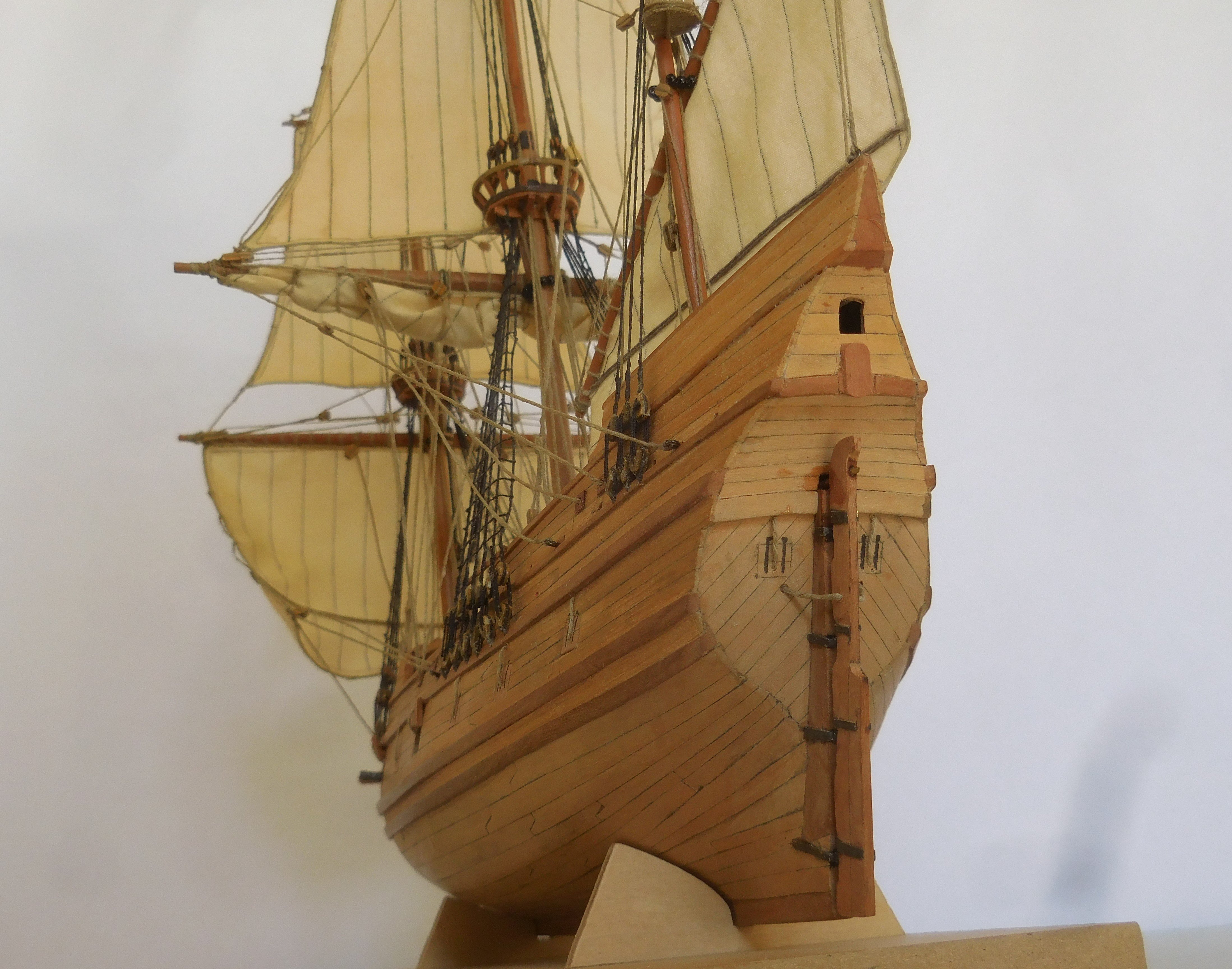
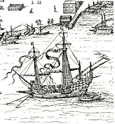
If you look for images from the 15th century, you will also come across this. There the bow is considerably lower and that seems logical to me in many respects. The captain and the helmsman now have a good view forward, which seems to me to be very useful in a naval battle. The bow now catches less wind. The excessively high bow of the MR seems to me very clumsy when boarding an enemy. The soldiers have to jump from very high to get on the deck of the other ship, I think I would break my legs. The highest guns have to shoot down, which seems to me to be rather impossible with the primitive cannons of the time. Constant
.jpg.a0c1c7a6d6a9502140c38ef2155a0958.jpg)
-
L'Amarante by marsalv - 1:36 - POF
tartane replied to marsalv's topic in - Build logs for subjects built 1501 - 1750
Is it possible to post some photographs of the ship and his history? Constant -
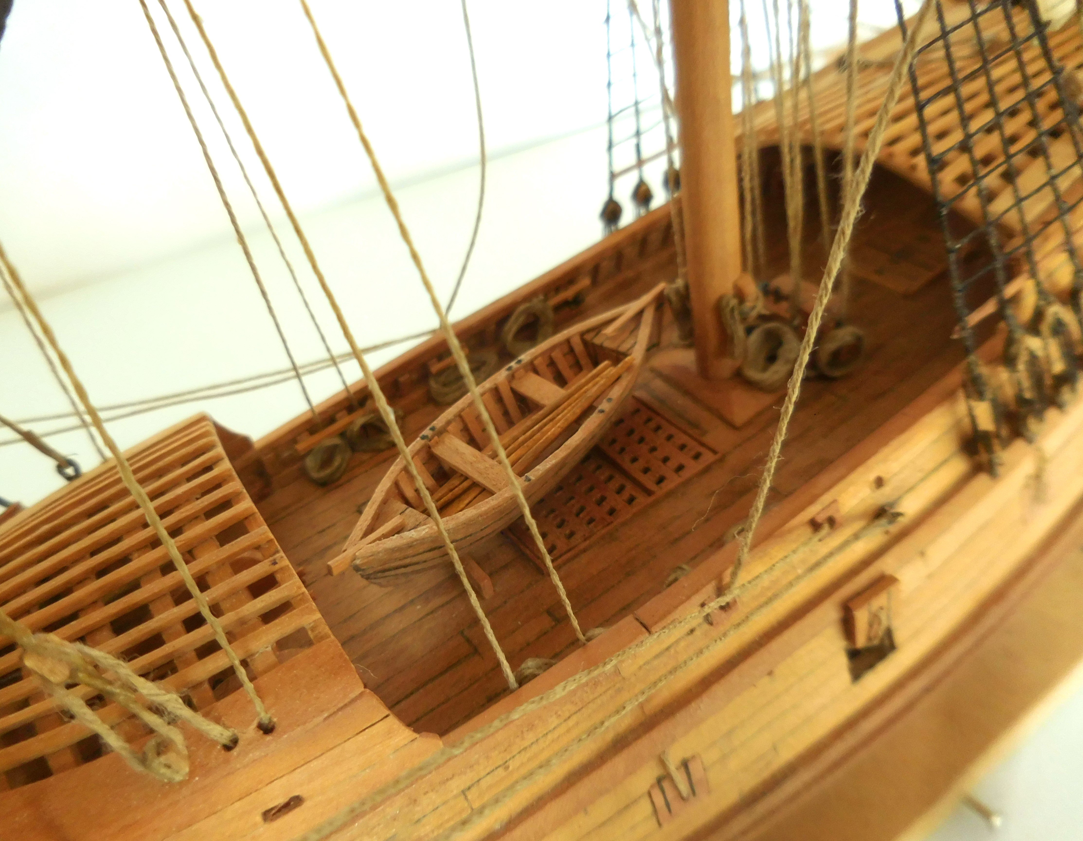
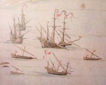
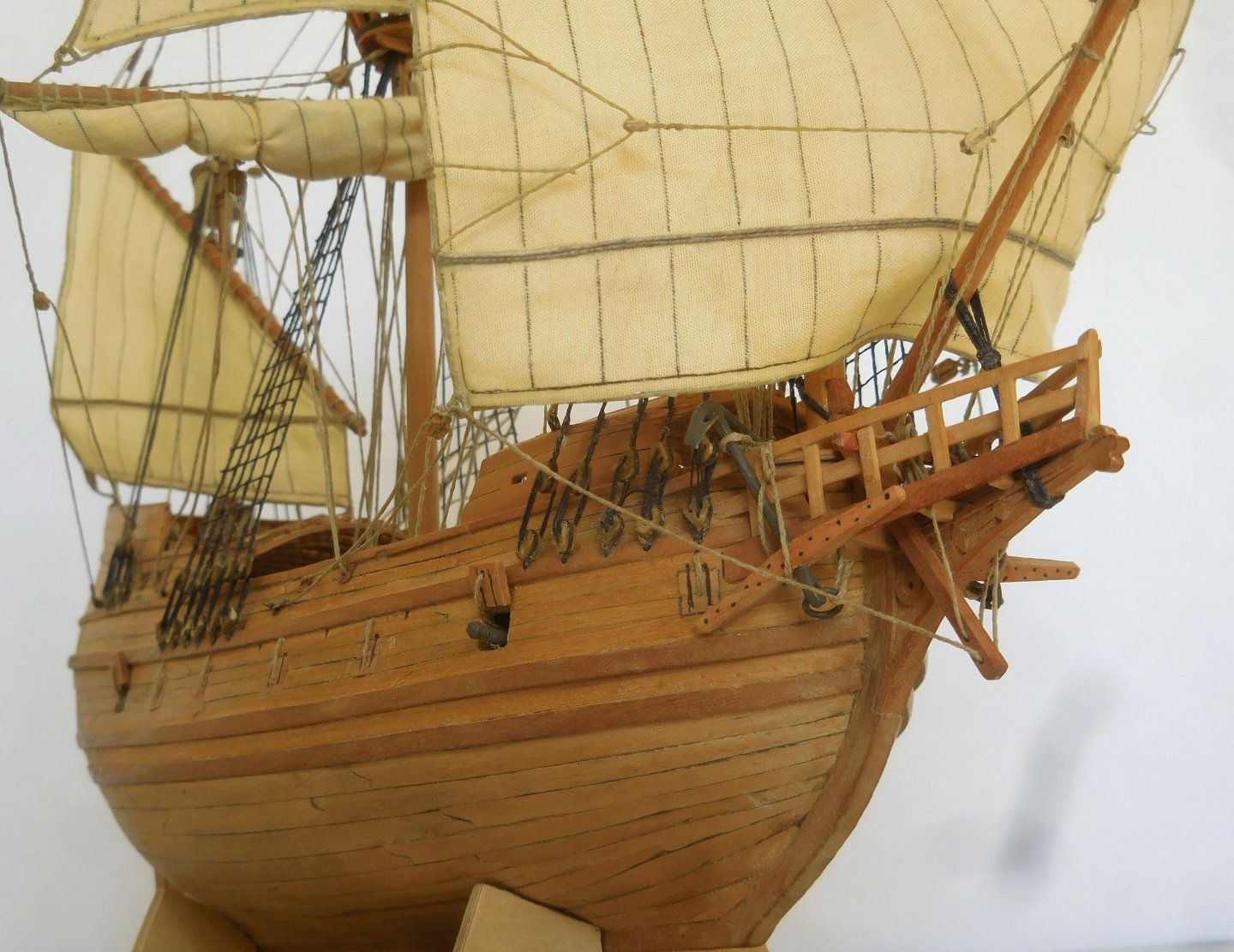
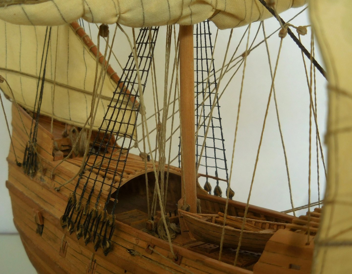
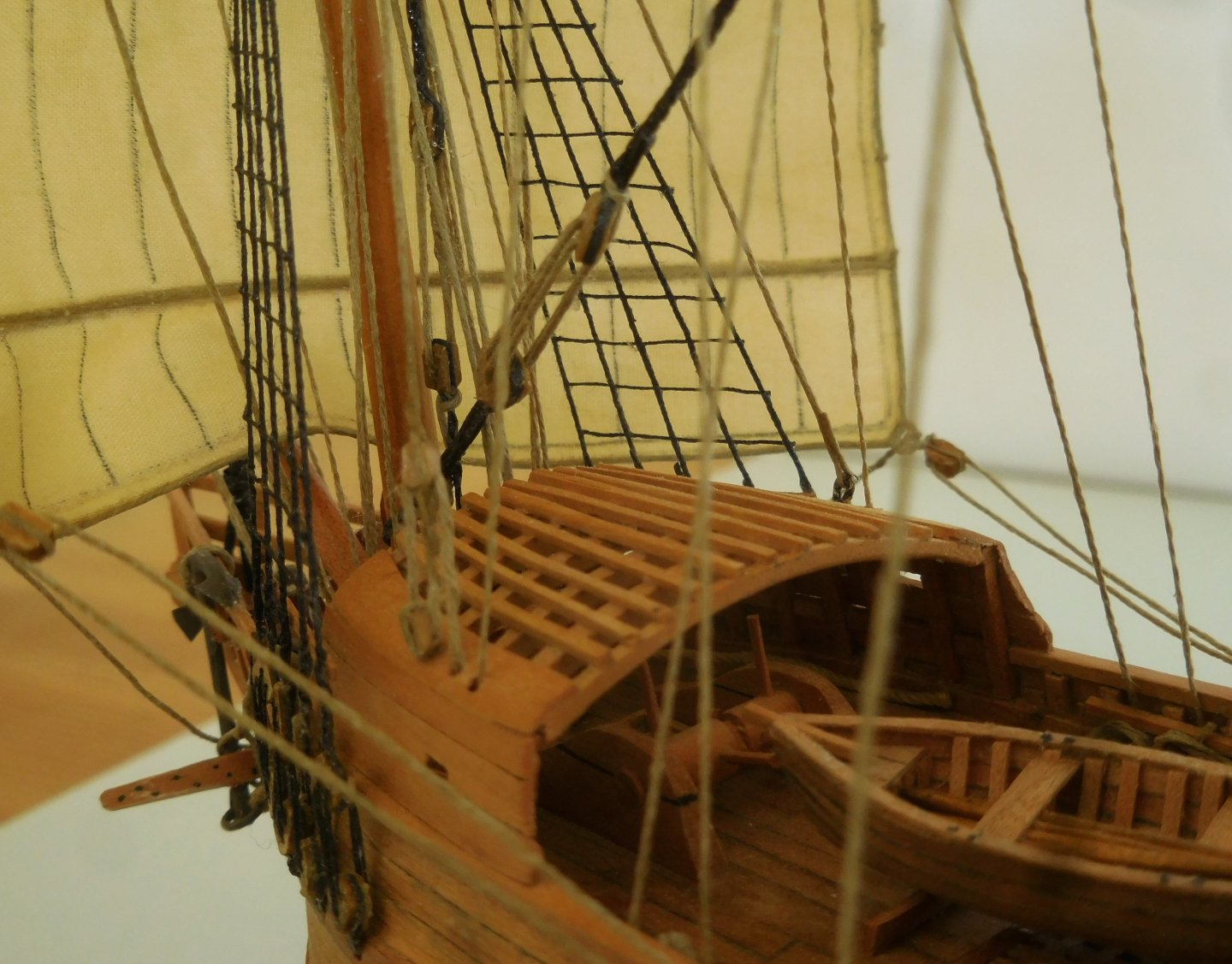
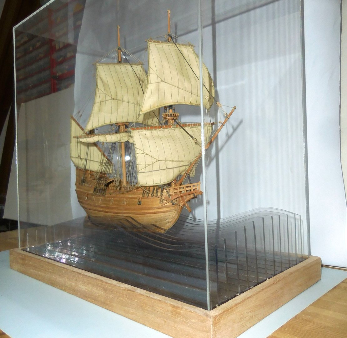
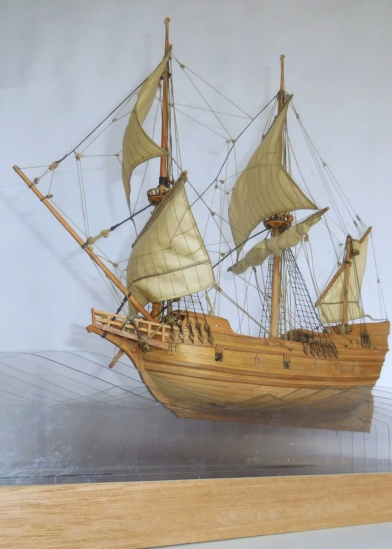
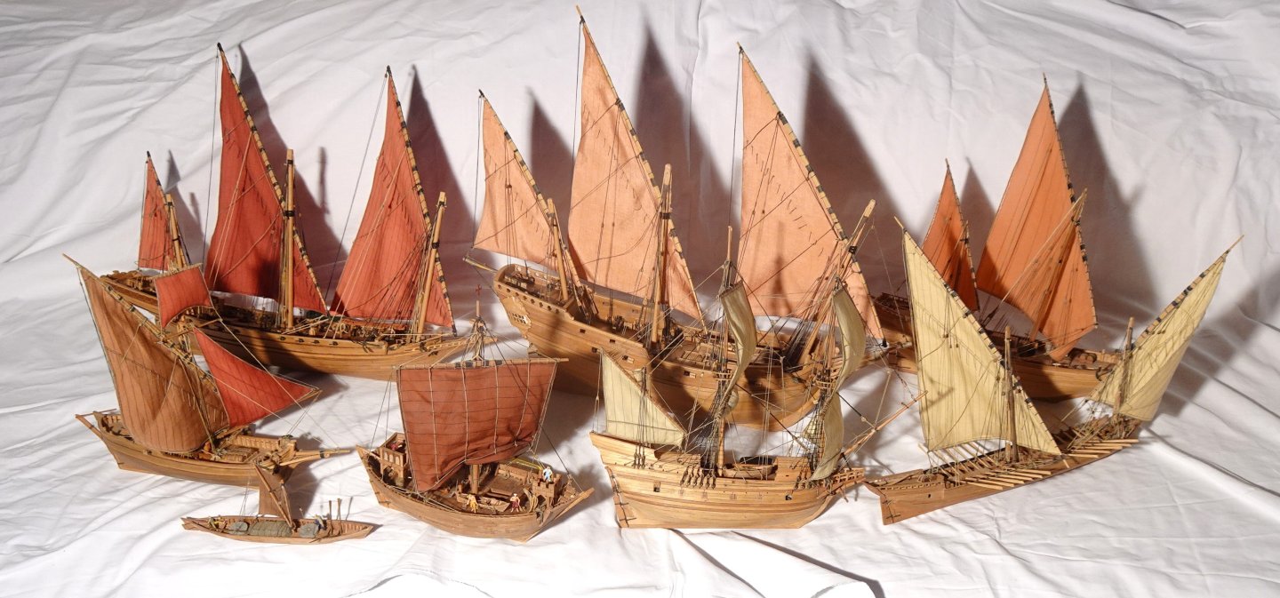
10, Pictures of the early Pinas. All ship models together so far. All on a scale of 1 : 87. Top from left to right; Chebec, Venetian Pinque, Ghanjah (Oman) Under; Tartane, Swelhals, Cog, Pinas, Galeotta. Not in the picture; Egyptian (Pharao time) merchant ship, English Canalboat, Stadsaeck (Zutphen 1684) See also; www.constantwillems.nl Constant


-
I am busy with the last episode. I show the photos in short time. Constant