HOLIDAY DONATION DRIVE - SUPPORT MSW - DO YOUR PART TO KEEP THIS GREAT FORUM GOING! (Only 20 donations so far - C'mon guys!)
×


tartane
-
Posts
127 -
Joined
-
Last visited
Content Type
Profiles
Forums
Gallery
Events
Everything posted by tartane
-
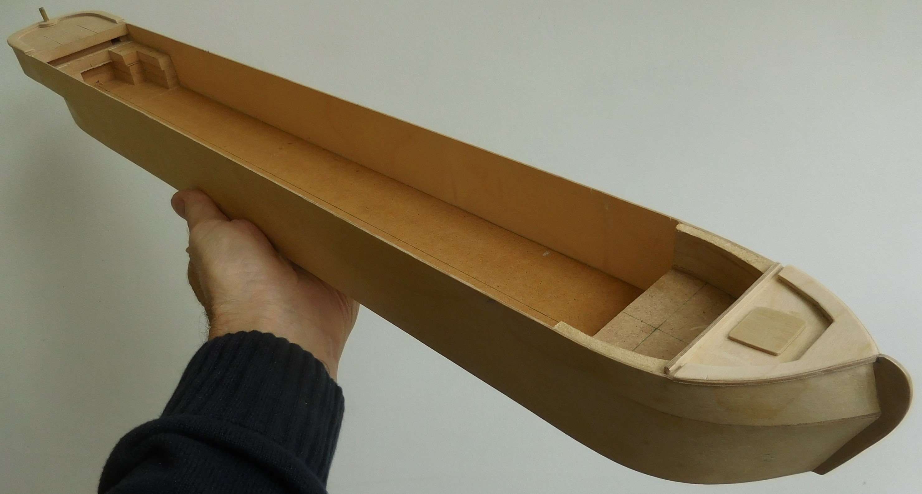
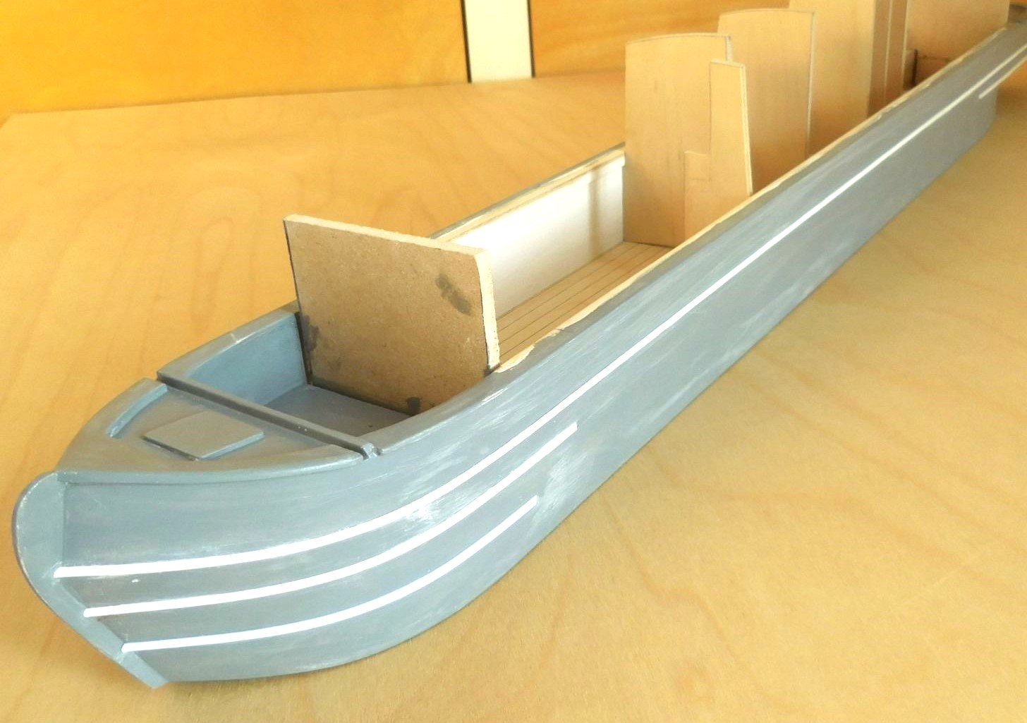
2 For the most part, the hull of the model is built of 8 mm thick MDF. This allowed the structure of the boat to be determined. In that structure, the location of the engine, the fuel tank and the water tank were already taken into account. Strips of 1 mm thick plywood were installed along it. Curved round at the back and ending in a point at the front. After drying and filing, the characteristic bow was glued to it, which is almost the same for every narrowboat. A deck hatch was then placed on the forecastle and later also the filler cap for the water tank. As far as possible, everything on the outside was painted in grey. Commercially available semi-circular strips of PVC were used to make the protruding edges along the hull. These were glued to the hull after examples in photos. These edges are intended to protect the hull when sanding along the edges of the locks. In the last picture you can already see that bulkheads have been placed in the boat that form the partitions of the various compartments. A temporary bulkhead is placed in the front of the hull so that the boat could be turned upside. Constant


-
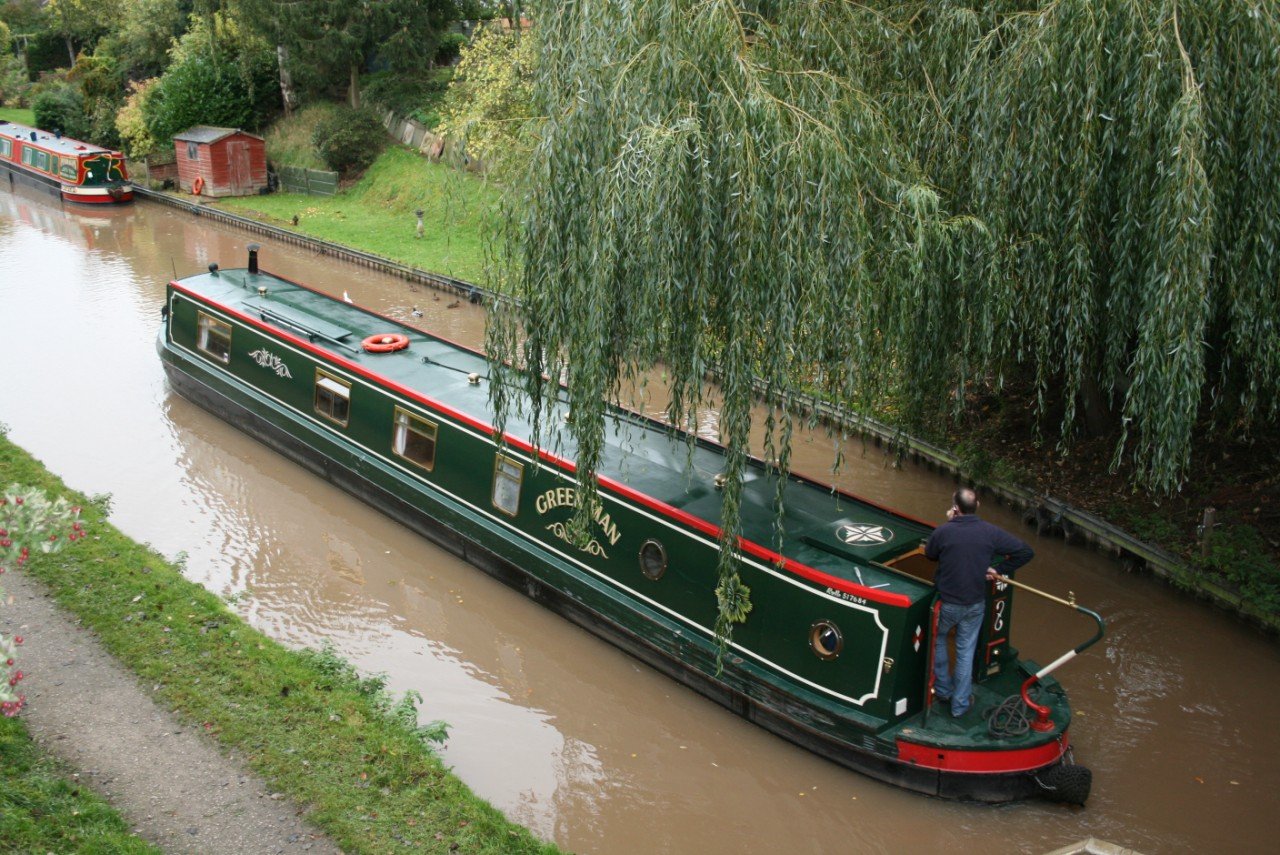
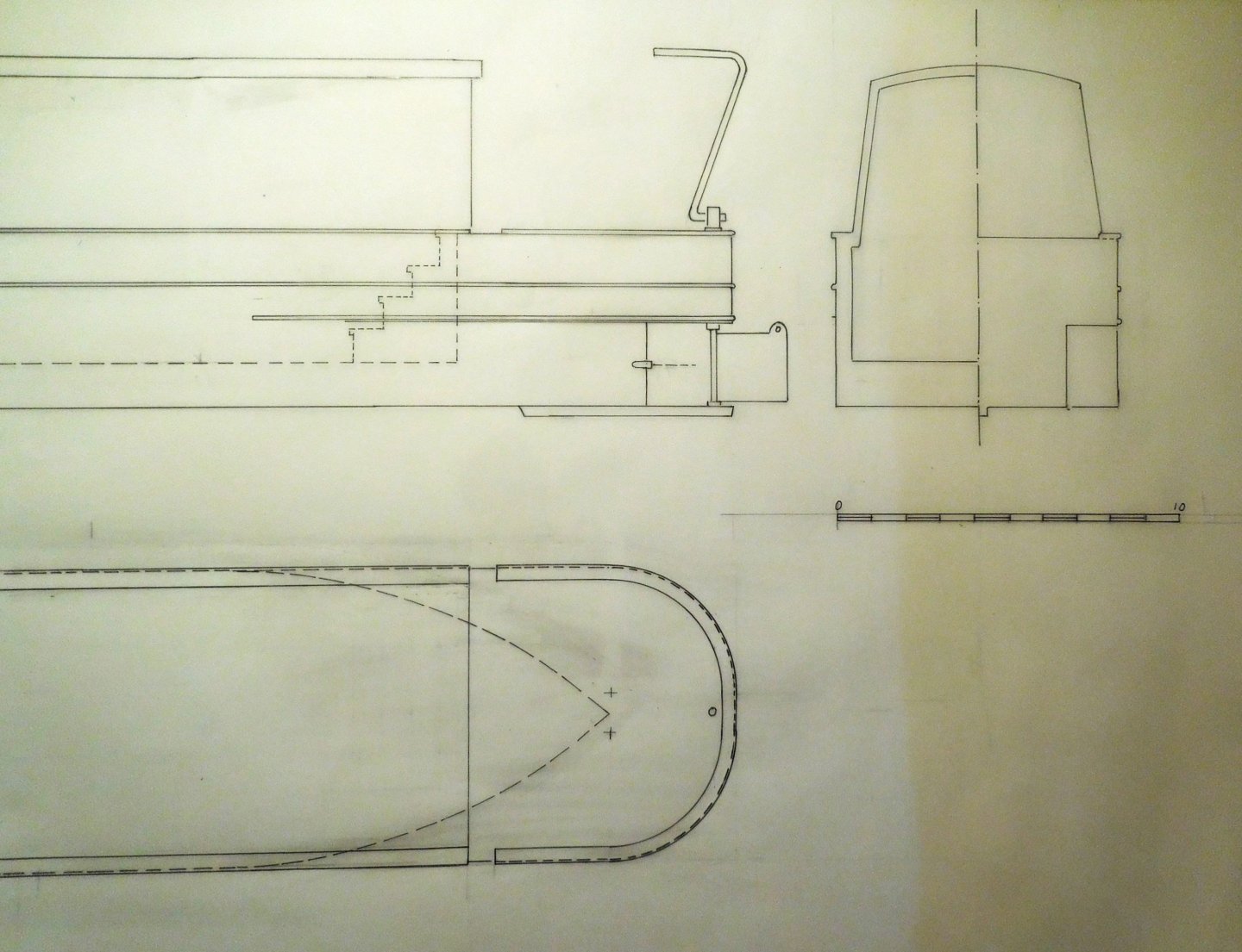
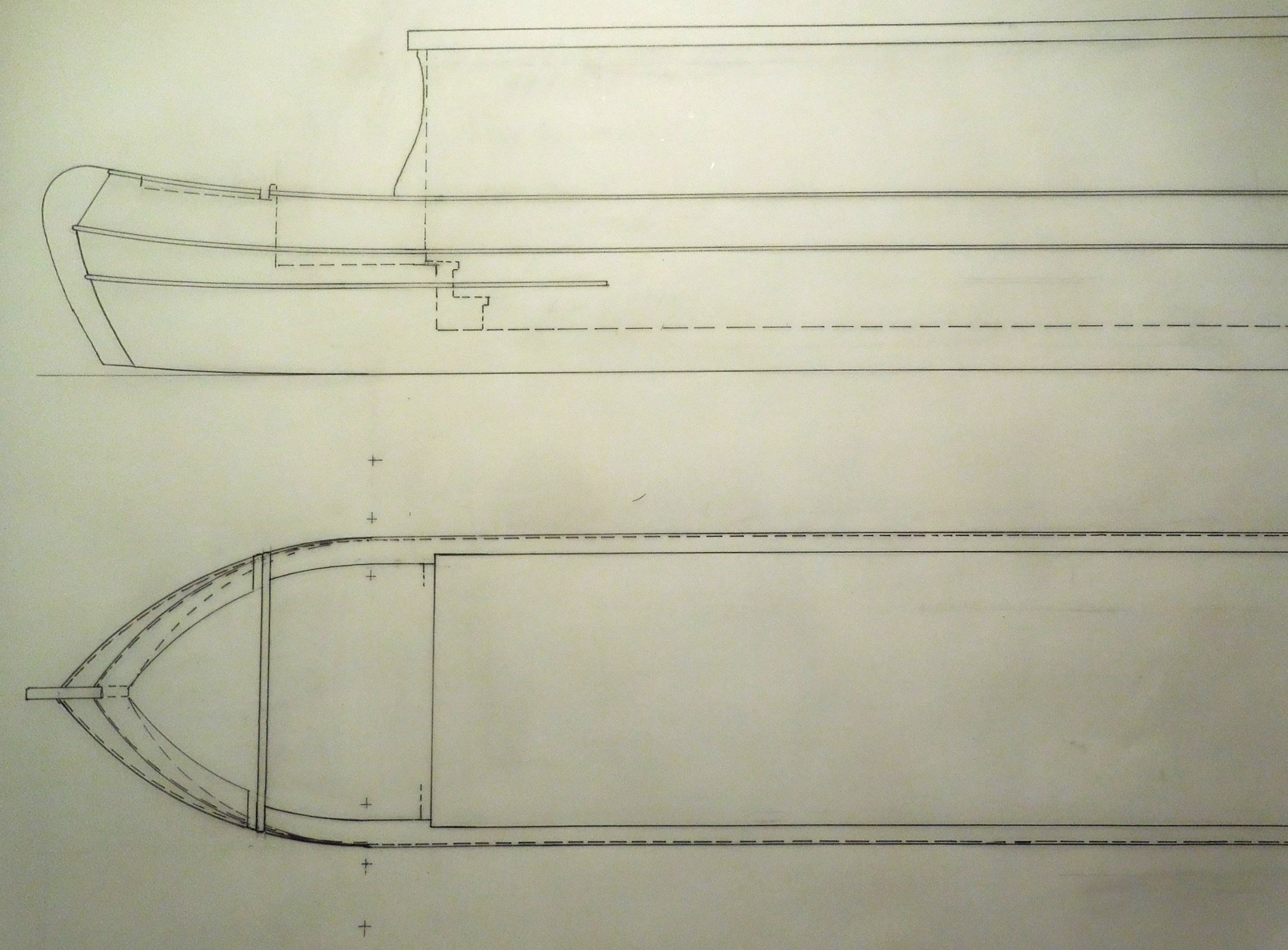
1 I built this model in 2016, so a few years ago, at the request of someone who had sailed on such a boat a number of times during holidays. In England it is possible to rent such a boat for some time and go out yourself in the canals in the middle of England. Originally they were cargo ships, but nowadays hundreds of newly built ones sail through this area. Moreover, many of these ships are permanently inhabited. My client wanted to use this model to show family and friends how much fun it can be to sail on such a narrowboat. Just an example They are very narrow, no wider than 2.08 m, which is necessary to pass through the many locks that do not have a wider passage than 2.13 m. The maximum length is 21.9 m, which has to do with the length of the locks in those canals. I determined the length of the model to be 717 mm, which comes down to an actual length of 18 m, which is the most common occurrence in reality. The difficulty was that there were no blueprints to be found anywhere. Extensive research yielded nothing, so it seemed as if this belonged to the English state secrets. Only the head sizes are known. Still, there had to be a drawing and I made it mostly on the basis of photos of people so that I could determine the necessary measurements after comparing and calculating. The client gave instructions for the layout of the interior. Drawings of the layout of such boats were available at the various rental companies, but they gave no indications about the construction and the heights. Photos of the boats lying on land for maintenance gave clues about the situation below the waterline. With the help of all this data, I made a drawing on a scale of 1 : 25 that served as a working drawing for the construction from that moment on. The stern The bow As a result, it has become a model of a non-existent boat, which accurately meets the standard dimensions. The painting is entirely at own discretion. By the way, it could be that there is a boat sailing around in this outfit, because after a quick comparison with photos it turns out that no two boats are the same. Constant

-
Two beams next to each other between which the foremast is clamped? Constant
-
Translate the text to English,. To do this, select the text and a message will appear;; translate section to English or any language you want. In the upper right corner of your screen, the translation will appear, then go to; translate entire page, and everything will be fine. If you want to enlarge or reduce the drawings, go to a copy shop. Write on the drawing you have exactly how much you want to enlarge it, for example 0.58 x and give it to the man who is going to do it. Always works, Constant
-
I read that you were harassed by a member on a previous forum. That happened to me when I was on the model building forum in the Netherlands. Eventually I left and now feel more at home on this forum. It may be about the same person that has caused many people to leave. Was his first name Stephan? Ridiculous that something like this happens. I can imagine that he is very jealous of your expertise. I think you do a great job and hope to hear more from you! Really beautiful. Constant
-
Yesterday I saw your report on this project for the first time. Great to see and read! I will follow you because I am very curious about the sculptures you are going to make. I built a few ships that involved quite a bit of carving on a scale of 1:87. I made that from pear wood that I selected from old utensils. I plan to build a state yacht on that scale but I hesitate because I don't know if I can finish the many sculptures. I hope to learn something from your reports about materials and methods. Constant
-
It amazes me to see how here a kit is put together. This isn't the right place, is it? Constant
-
Beautiful paintwork! I know how difficult it is to paint small details within the established lines. Recently I saw a report on TV about the excavation of the remains of the Mary Rose that have yet to be found. It emerged that they may also have found remains of the bow, at some distance from the wreck. So who knows what the results will be.
-
Museums all over the world have more or less experience with lead corrosion. See the accompanying report where much is explained about this problem. Naval Sea Systems Command > Home > Warfare Centers > NSWC Carderock > Resources > Curator of Navy Ship Models > Lead Corrosion in Exhibition Ship Modelsnavsea.nav Constant
-
You mentioned the disastrous effect in the combination with lead and wood. I had experience with that too. I do know that it mainly occurs when a model is set up in a completely closed display case. It is then the gases released from the wood that affect the lead. If the display case itself is sufficiently ventilated, the destructive effect will not be too bad. I notice it when I remove a display cover over my models, then you can smell the wood gases that are in it. And that has to be able to go. A number of models I've built are still without a display case, and nothing has happened to them for years, except that I have to remove the dust every now and then. Do you know the book: "The age of the Galley, Mediterranean oared vessel since pre-classical times", written by Robert Gardiner in 1995. A fantastic book, highly recommended for anyone who is working with such ships. Funny thing is that the writer was not aware of the existence of a Turkish galley ship from the beginning of the 17the century that has been completely preserved and that is now in the maritime museum in Istanbul. If he had known that, it would certainly have become a separate chapter in his book. I visited that ship and took some pictures of it. If you want to know more about that, let me know. Rest me to say that I follow your exellent craftsmanship and thorough research closely with great admiration! Constant
-
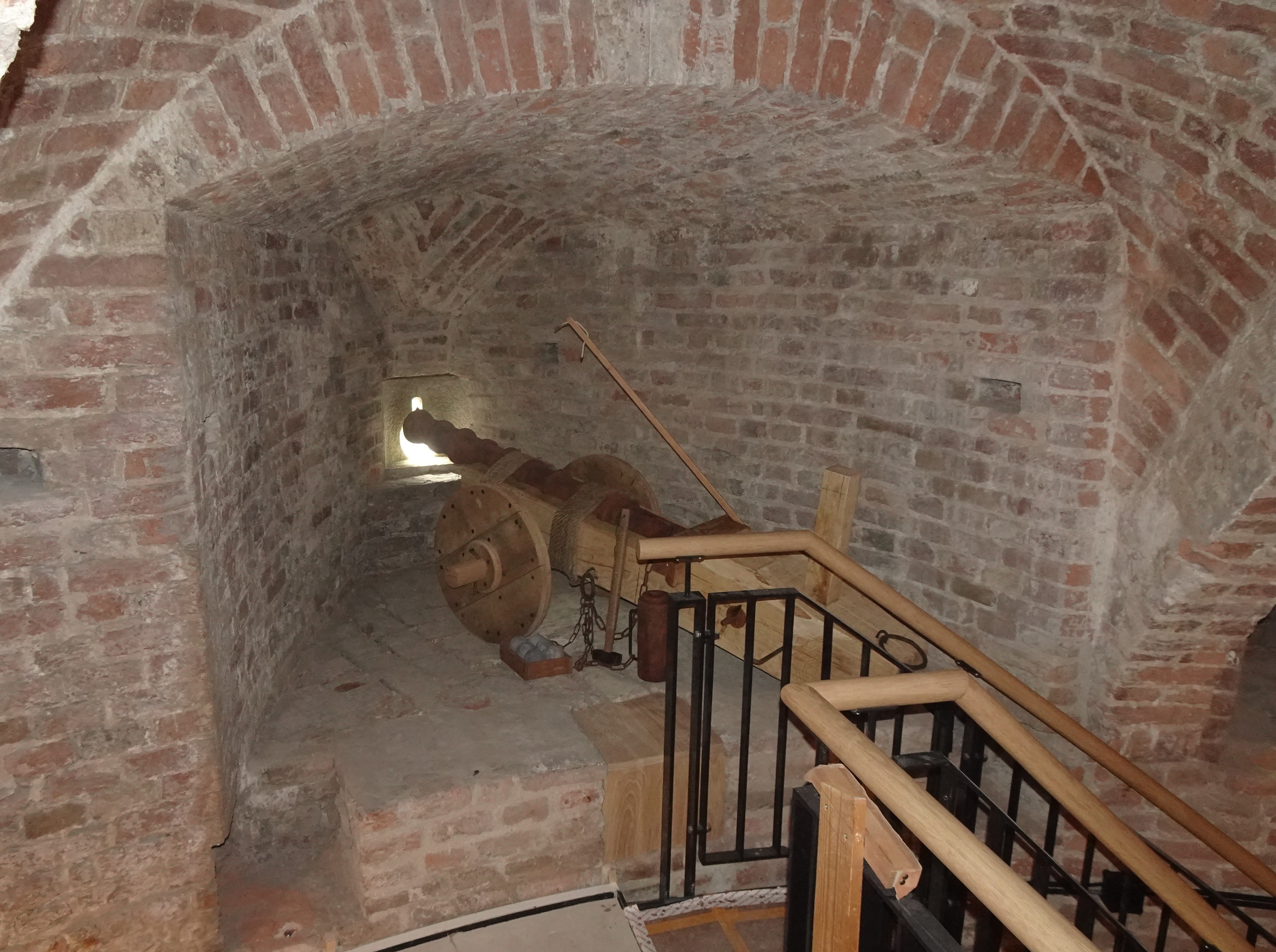
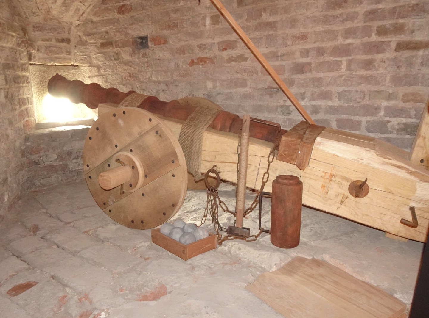
11 The cannon I built is derived from the cannons found on the Mary Rose and from examples of such cannons that have been preserved throughout Europe. Several museums have these examples. Since no cannon from that time looked exactly the same, I could afford to build a cannon that fit within the available space in the medieval gun tower in Zutphen. There are several bills in the 15e century that deal with the purchase of those cannons. The much larger cannons, one of which was also ordered in Zutphen in 1457, were not on wheels but lay on the ground. I did a lot of research on that to understand what kind of cannon was purchased here in 1457. We knew the weights of the barrel and the snelleke. Since 1457, everyone believed that this cannon had been in the tower, but the enormous weight and the diameter of the available embrasures did not match. After a lot of calculations and research into such existing cannons in Ghent, Edinburgh and Dresden, I came to the conclusion that the cannon must have looked like the photo of a model of it that I made myself. Several experts in the field have examined my calculations and came to the same conclusion. The cannon in Ghent (Belgium) That was the reason that the municipality of Zutphen asked me to make a replica of a cannon that could have been in the tower. After research, using as examples the cannons that still exist and have been excavated, I made the cannon that is now in the tower. In the gun niches you can see traces of construction that indicate that they were fixed during the firing. Look at the first episode that I wrote in this topic. The niches opened onto a very heavy floor, on huge beams, which has now disappeared, over which it is clear that the cannons were driven over in order to be able to fire in the right position in other niches. There would not have been a cannon in every niche. The same thing happened on ships at that time. A small ship like that of Willem Barentz in 1596 had 14 gun ports. There were 16 people on board, so it is clear that there was not a cannon behind every gun port. Possibly there were no more than two. So it's very likely that the cannon I built was on wheels. Because the barrels of these guns were often tied with ropes, it was possible to disassemble them and use them elsewhere in a campaign. In addition, the bottom of the embrasure is about 40 cm above the floor. Anyone who takes the trouble to search the internet for 15th and 16th century iron cannons will find images of such a cannon. Constant
-kopie.thumb.JPG.8ee8fd0b26aeb275df602c155df3740f.JPG)
-kopie.thumb.JPG.e9a53875ed7400a499ae751838839c18.JPG)
-kopie.thumb.JPG.91e89a323c2abc65c549f3b54e8f592b.JPG)
.jpg.7cf47084dc08876122173dc5b808471d.jpg)
-
10 The cannon is now in its final place in the medieval Burgundy tower. With these pictures I close this topic. Thank you so much for all the thumbs-up! Sincerely, Constant


- 23 replies
-
- 11
-

-

-

-
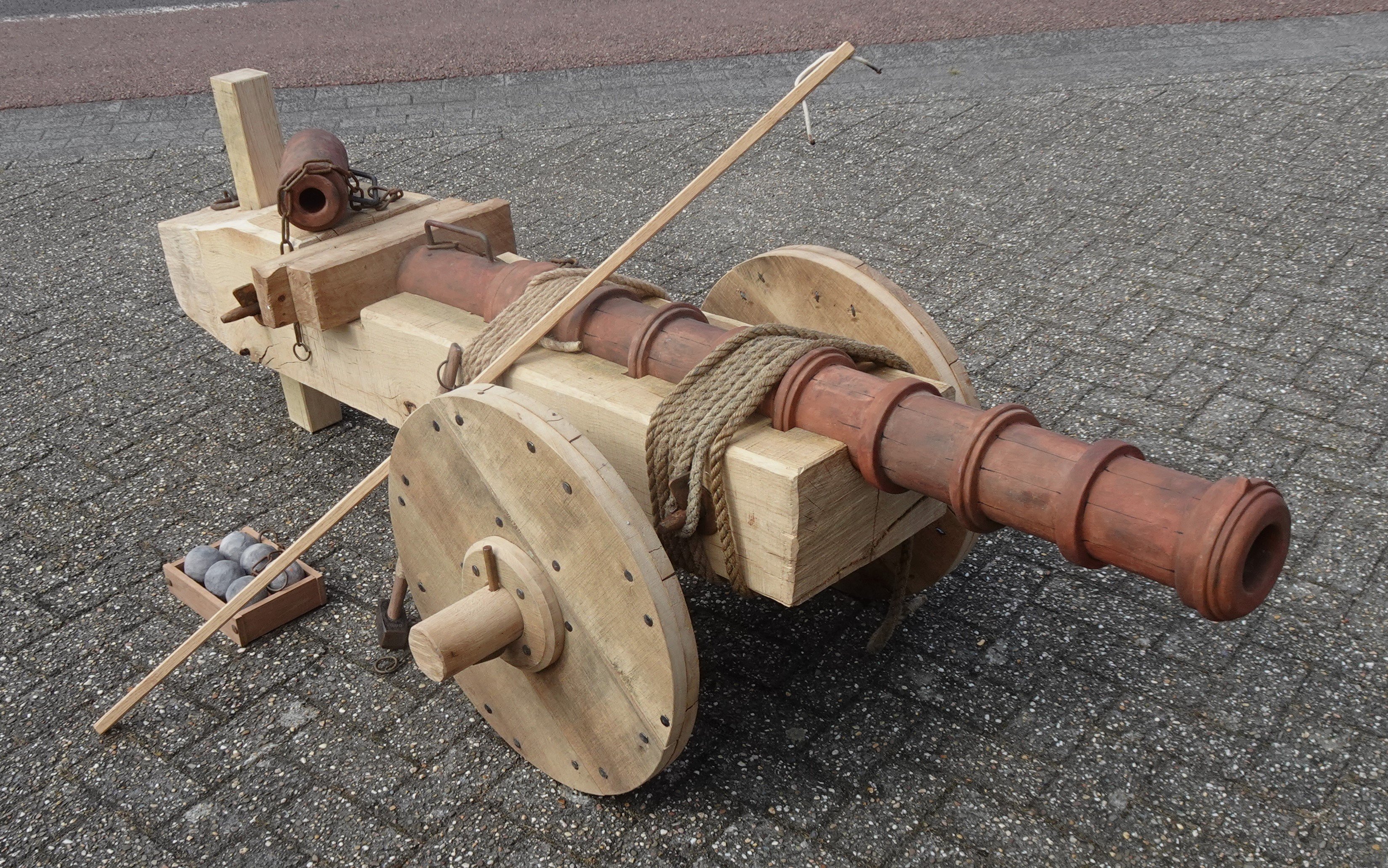
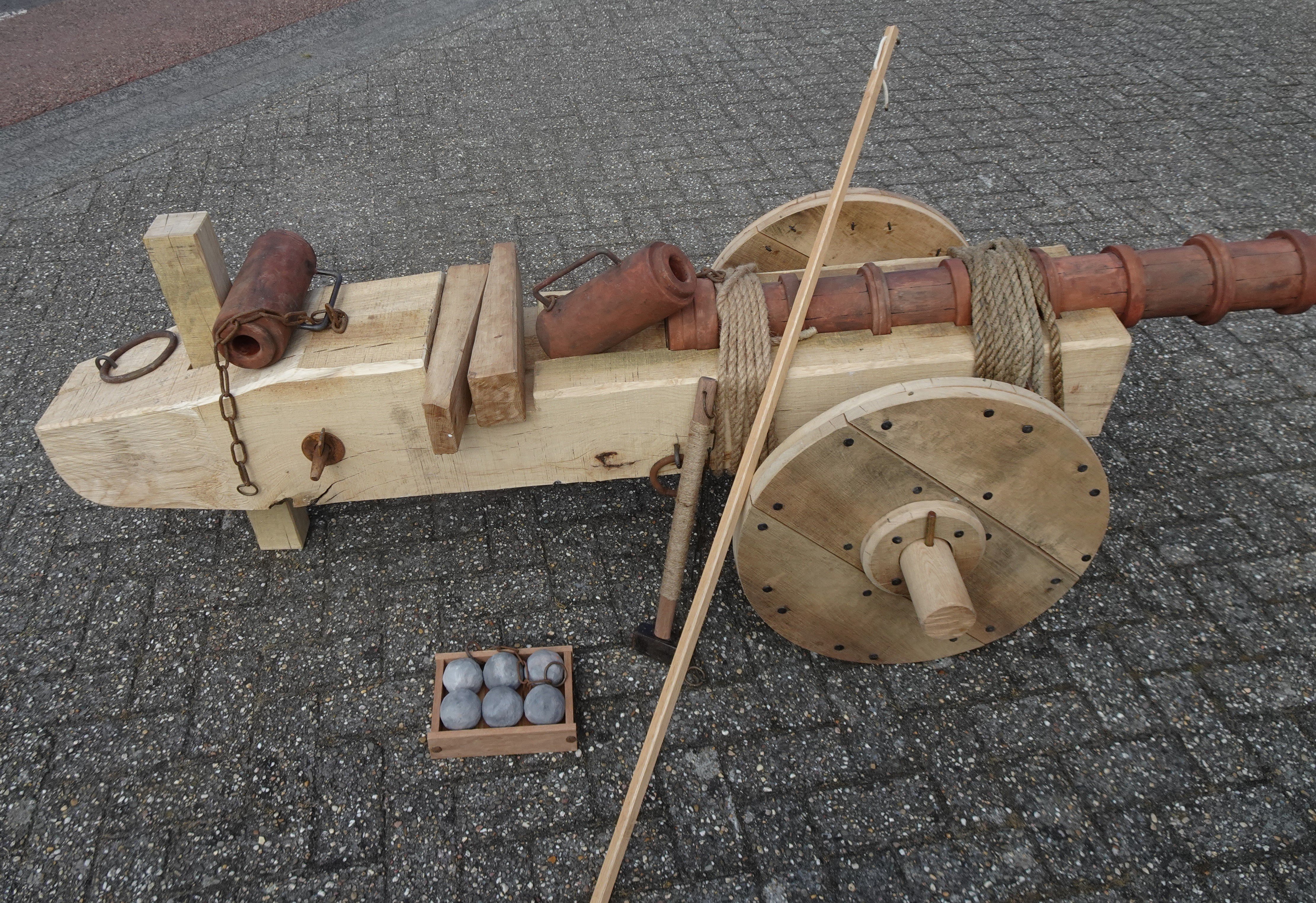
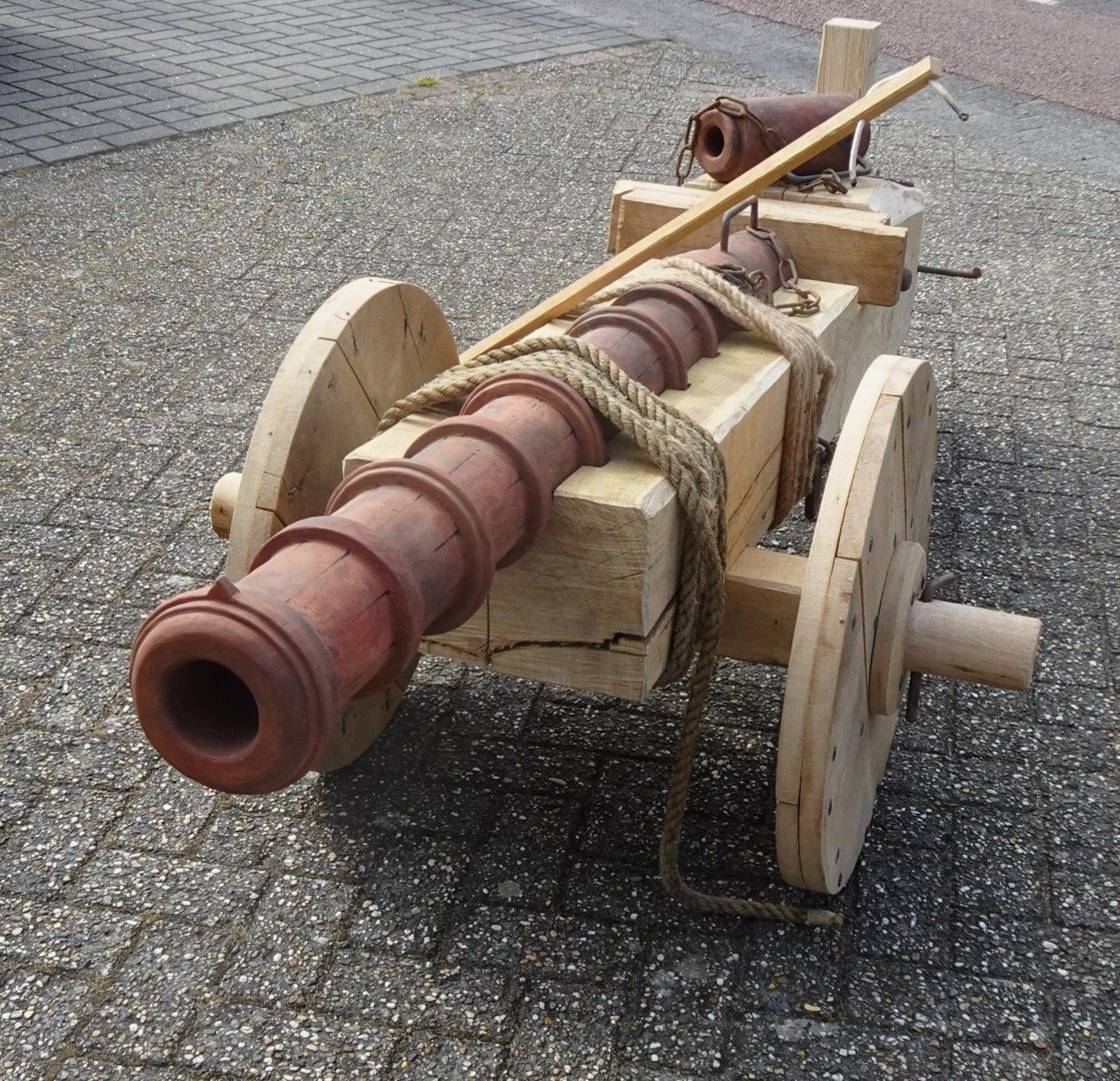
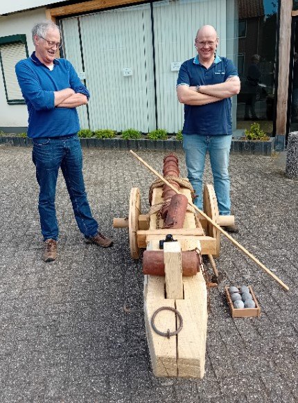
9 After the photo shoot at the contractor’s workshop. The cannon is now dismantled again and in parts it goes to the medieval tower where it will be constructed on its final place. This will probably happen tomorrow. I'm very happy with the result!


- 23 replies
-
- 10
-
-
-
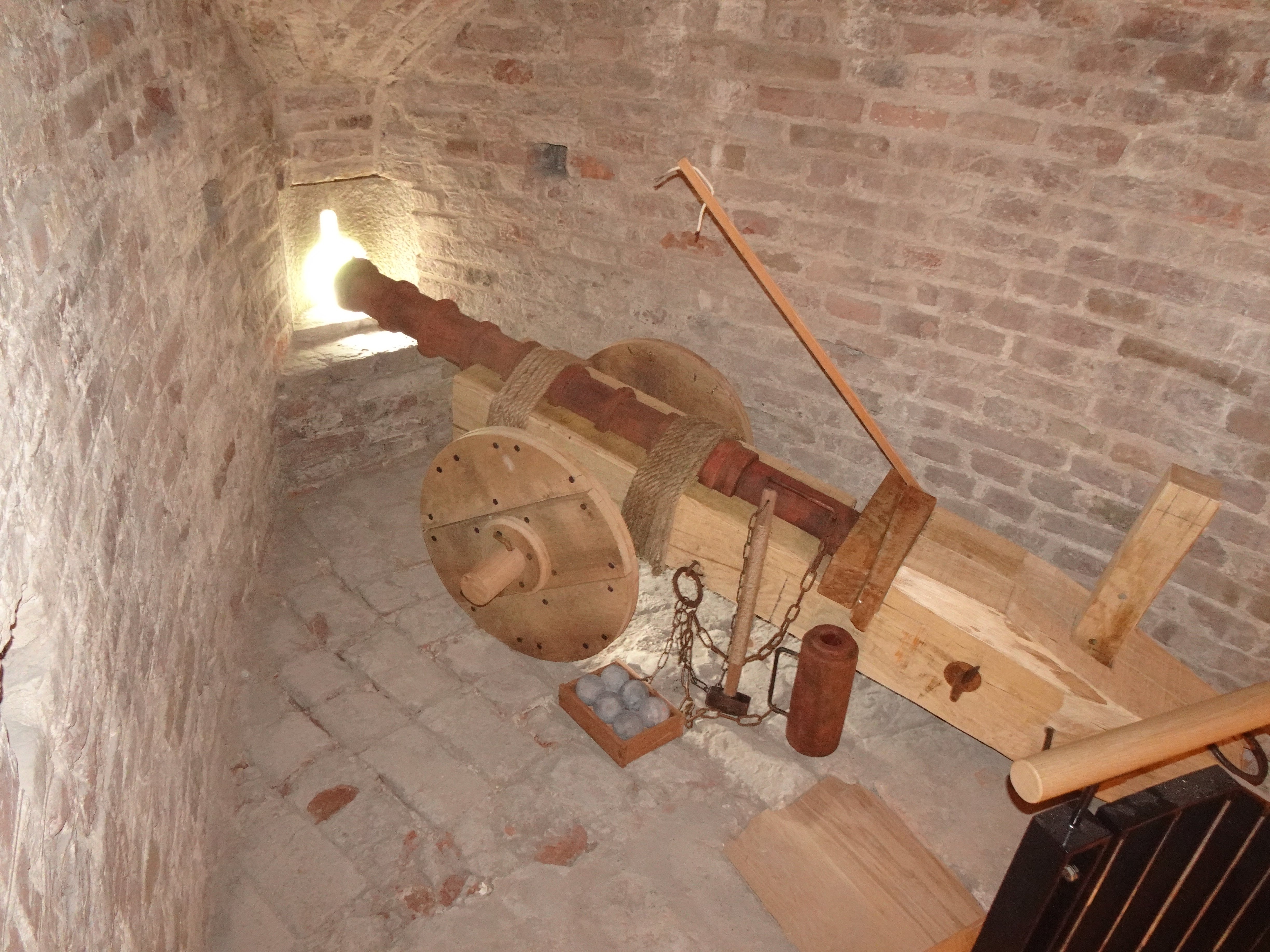
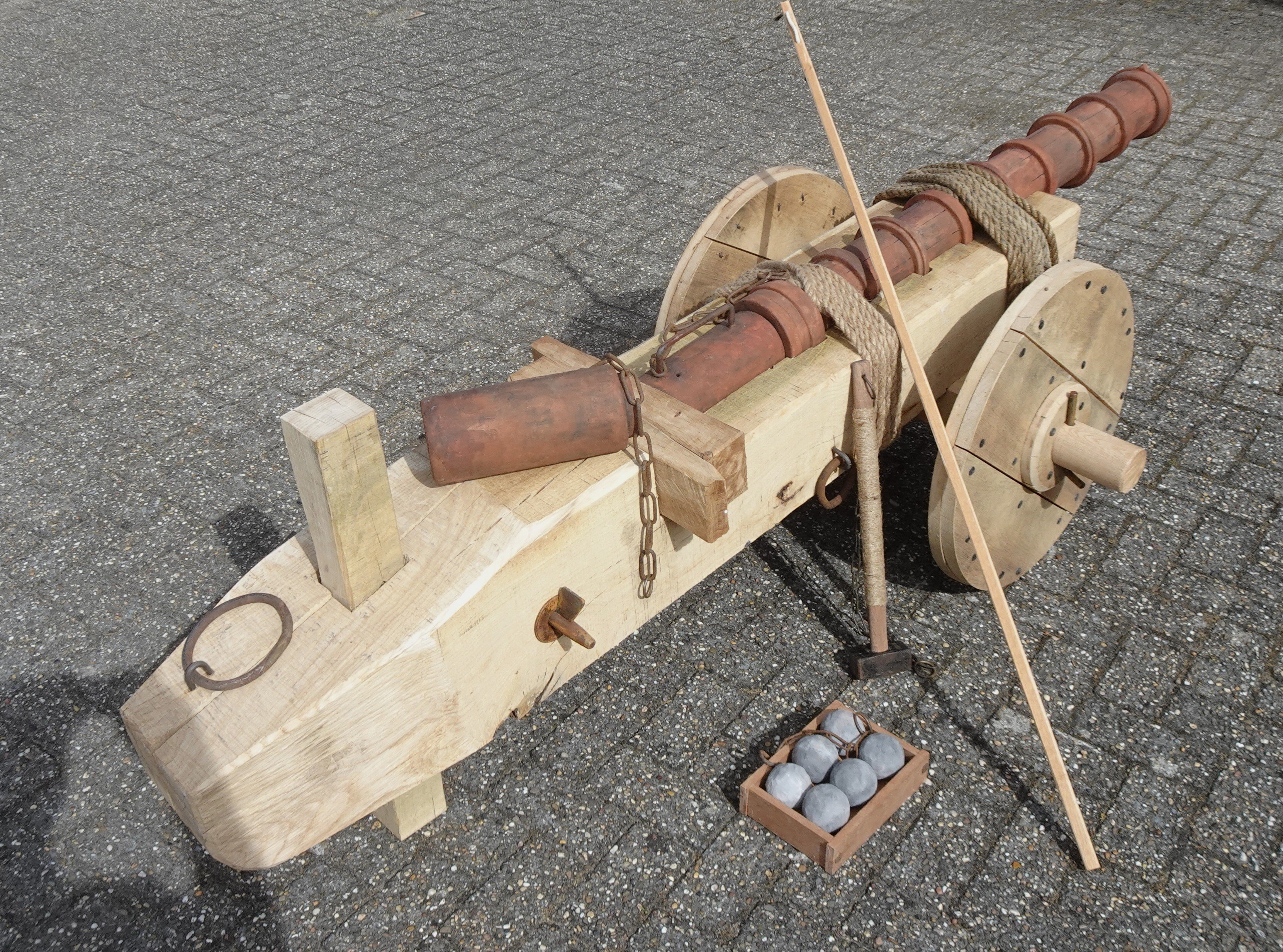
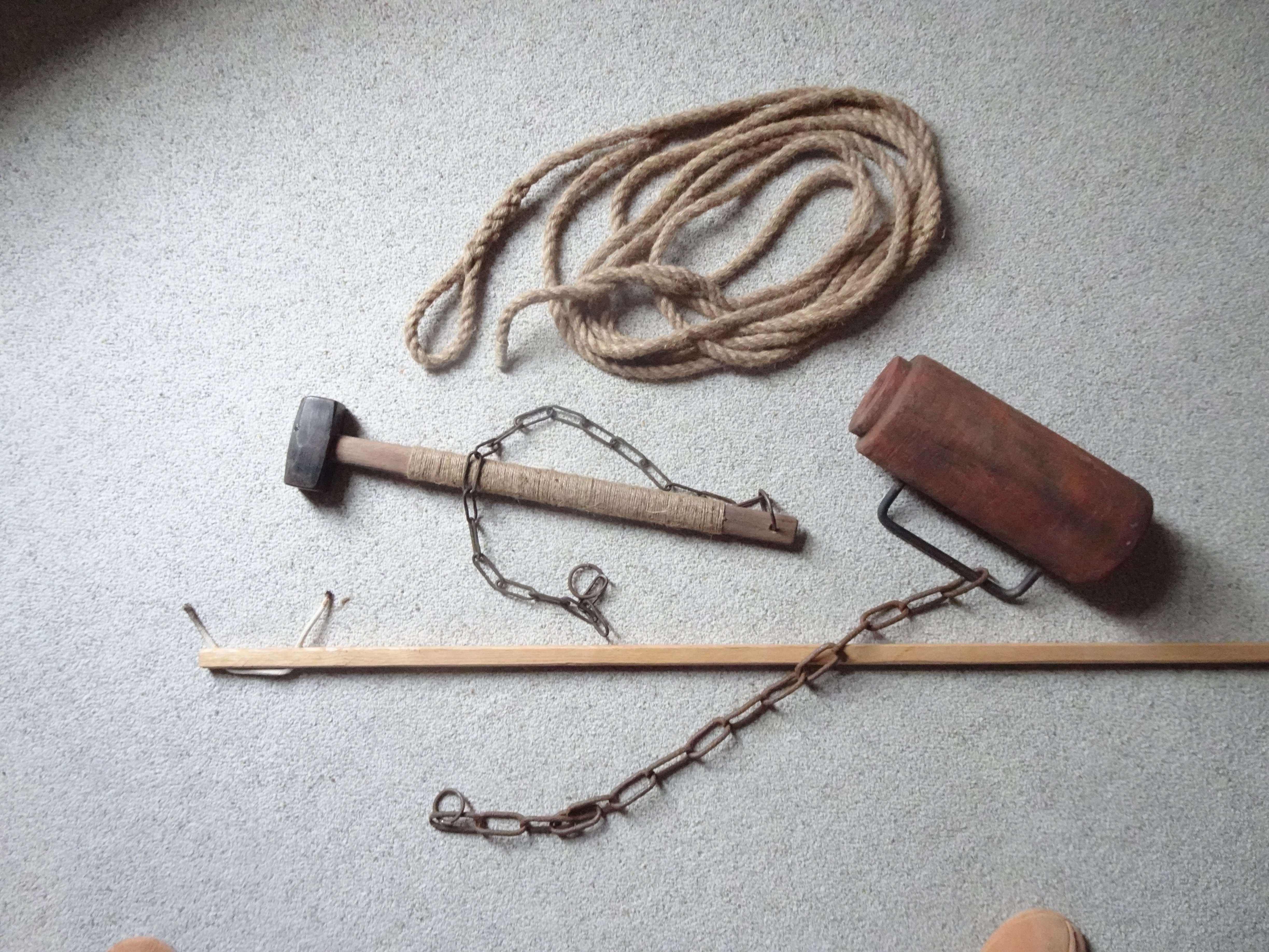
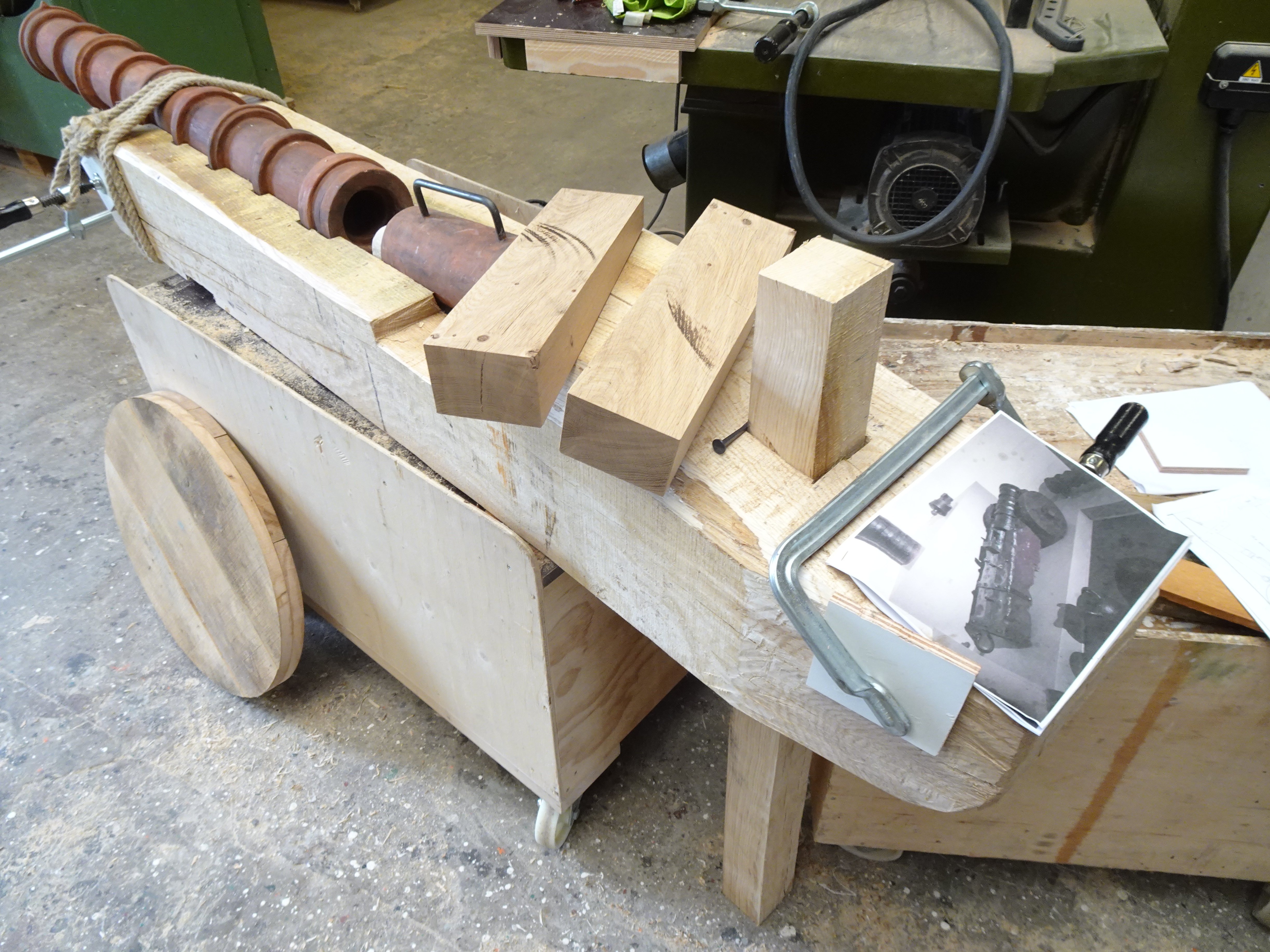
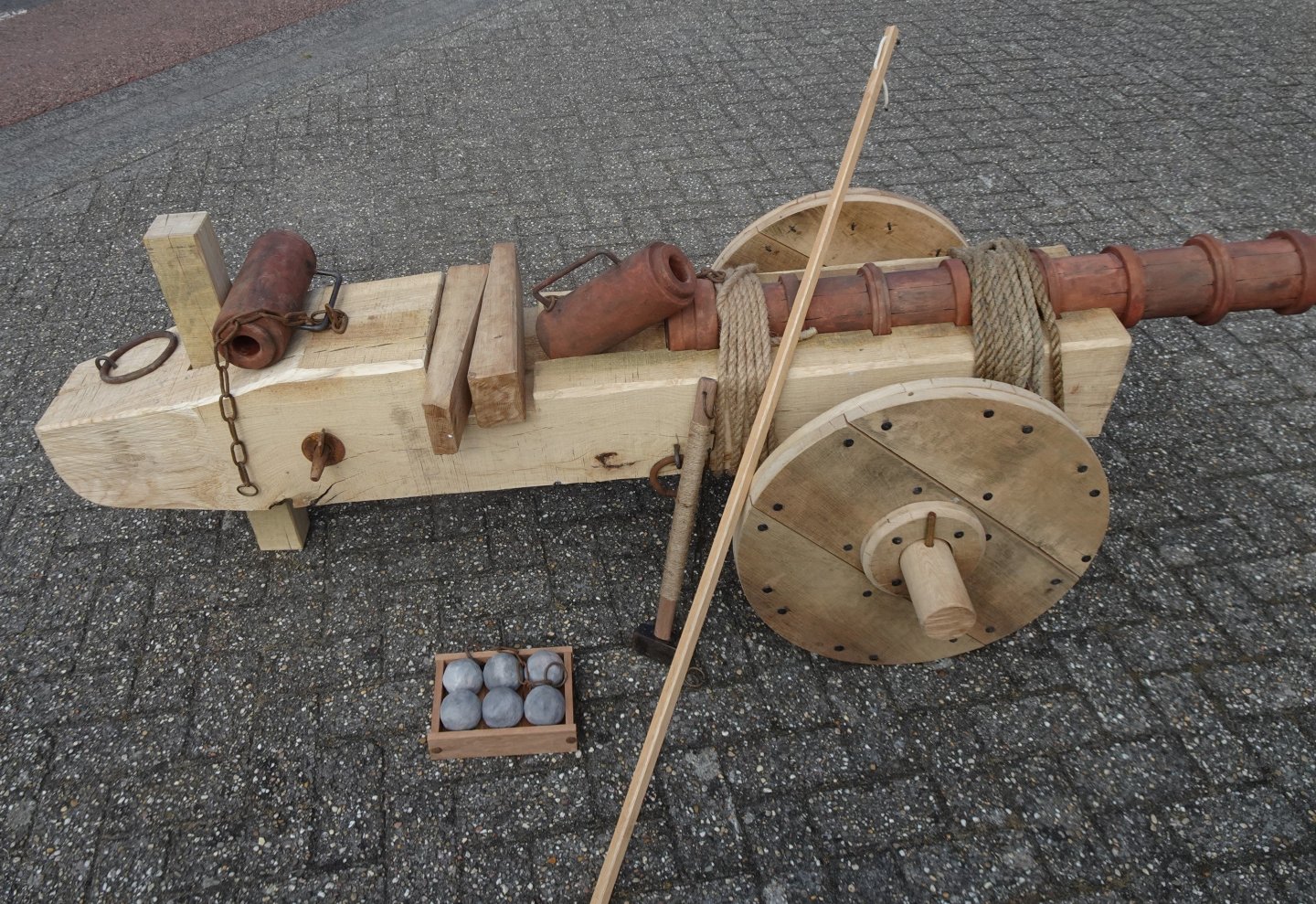
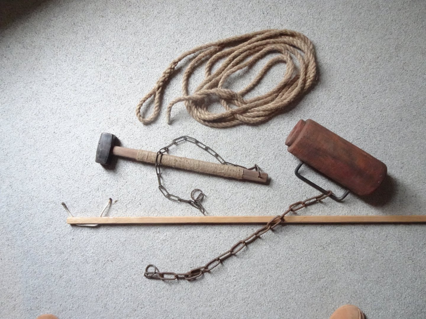
8 Indispensable tools for a 15th century cannon. Rope to attach the barrel to the carriage. A hammer to strike and loosen the two wedges for the breech A long stick with a wick De breech. The parts will soon be attached to the cannon with chains to prevent enthusiastic visitors from working with them!
-
Very expertly built with beautiful details, and clear photos. Congratulations! I have a question; Where is the capstan with which the great Ra is hoisted and with which the anchor is also raised? There seems to be more than enough room for it on deck. Constant
- 38 replies
-
- 1
-
-
- Santa Maria
- Nao
- (and 1 more)
-
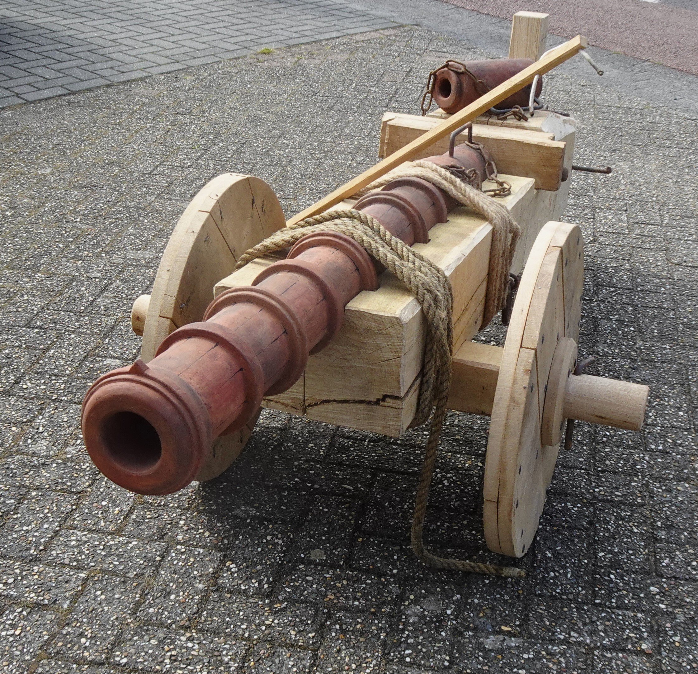
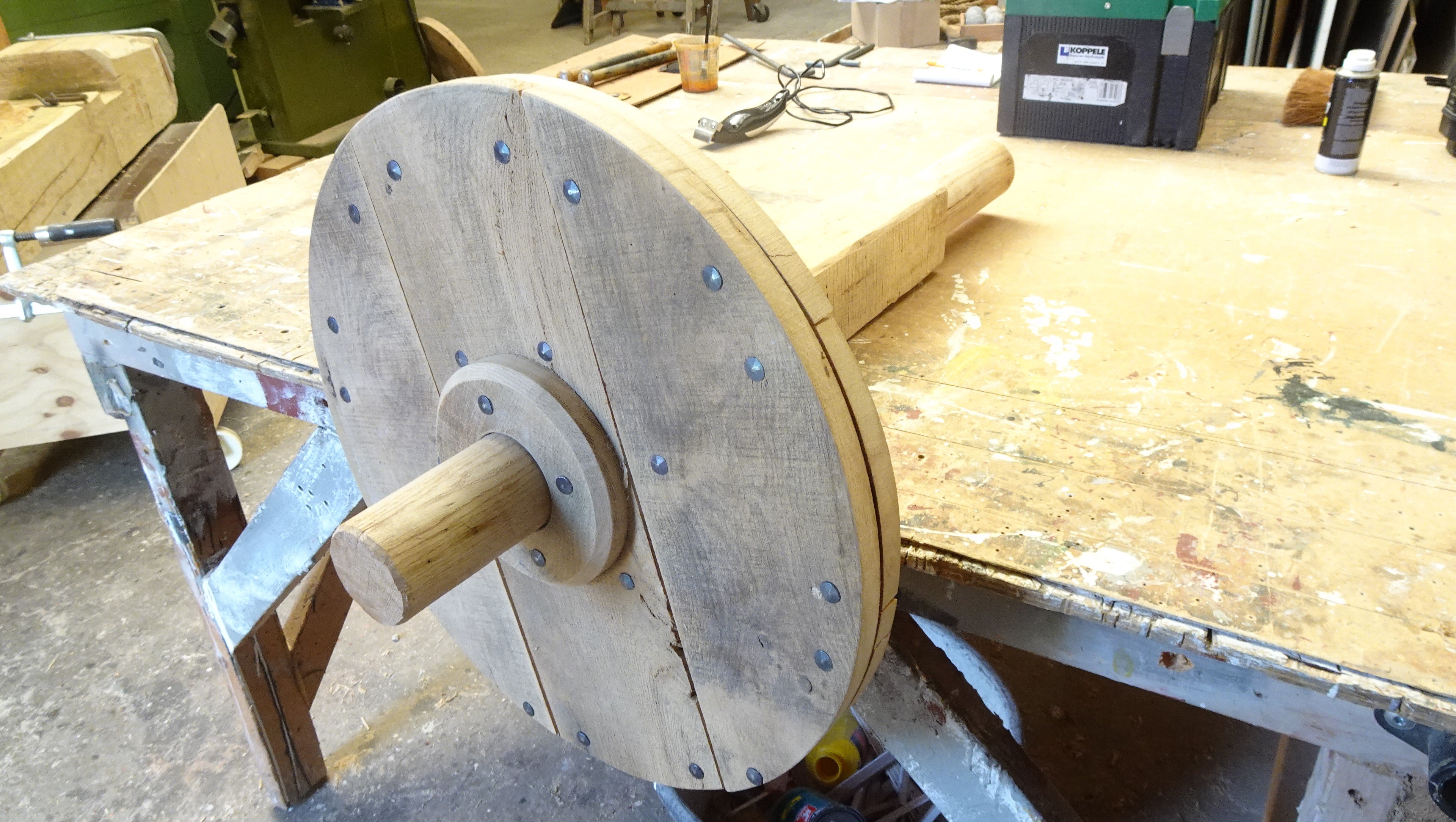
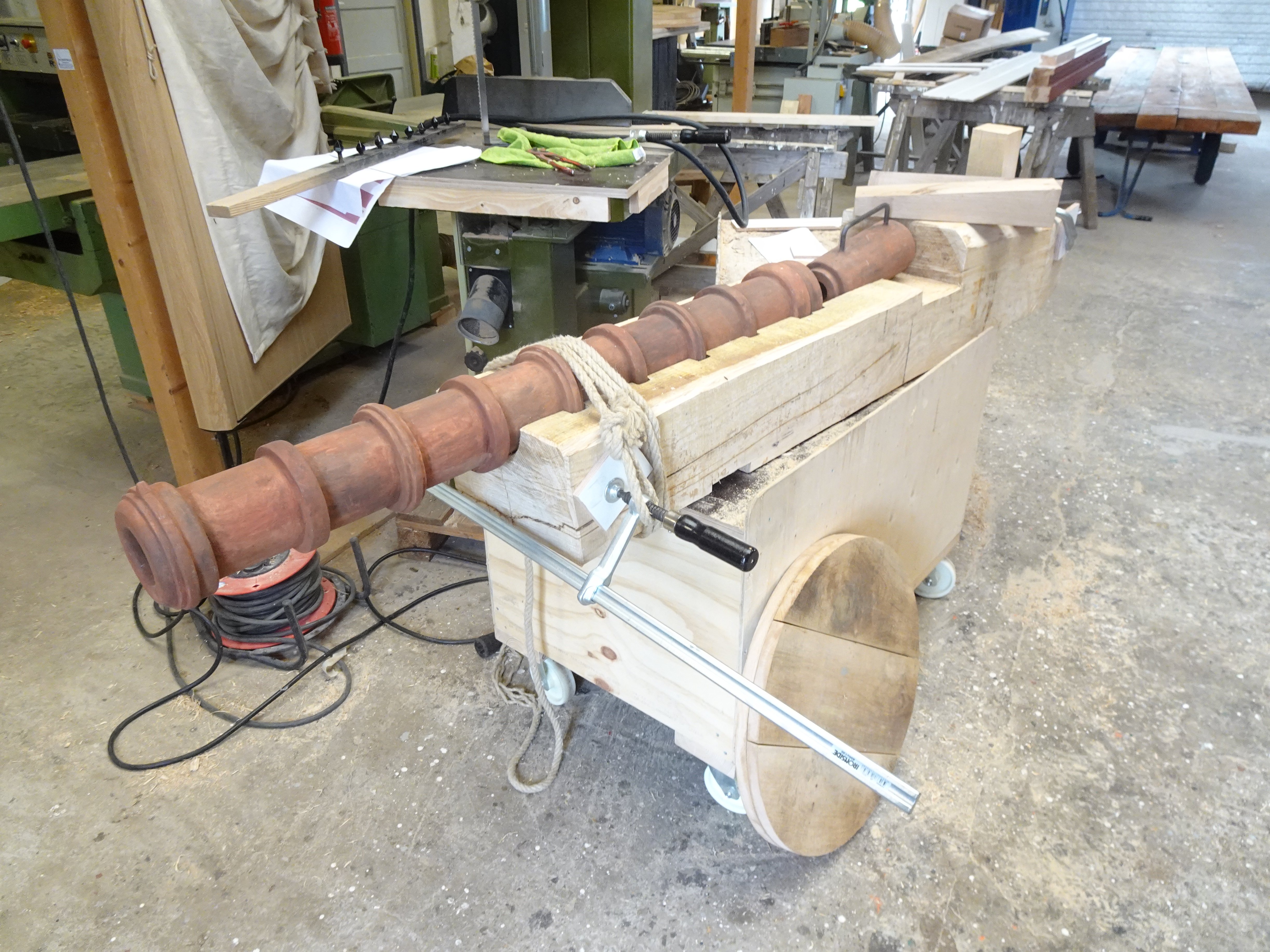
7 In the contractor's workshop, a lot of hard work has been done to finish the carriage. The cannon is now almost ready. Some of the parts are now in the workshop and another part is at my home. In the coming days, everything will be brought to the tower and assembled there.


- 23 replies
-
- 11
-
-
-
Well done Dave! Fine detailed work. Is the scale really 1: 72? It seems a lot bigger for me.
-
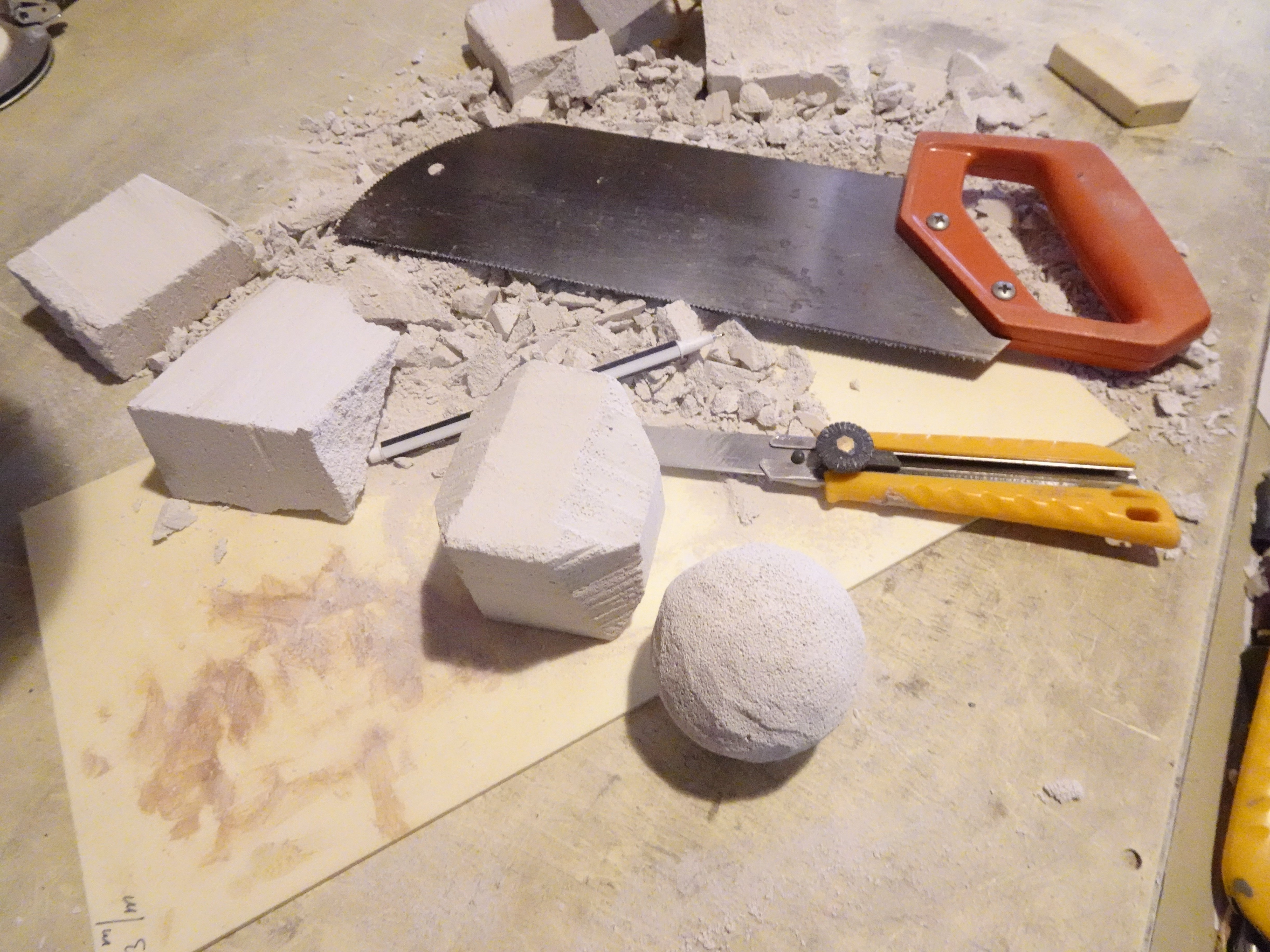
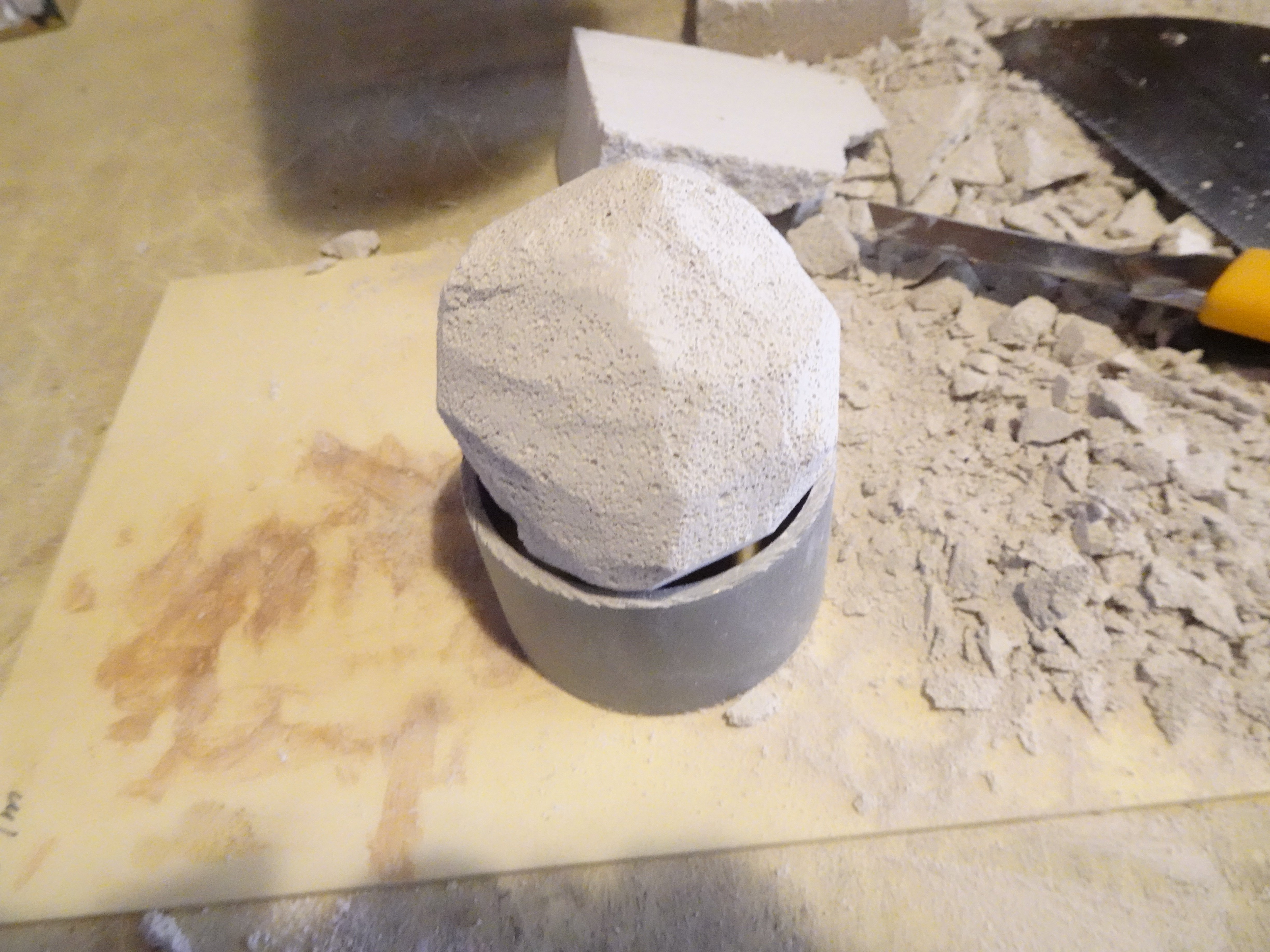
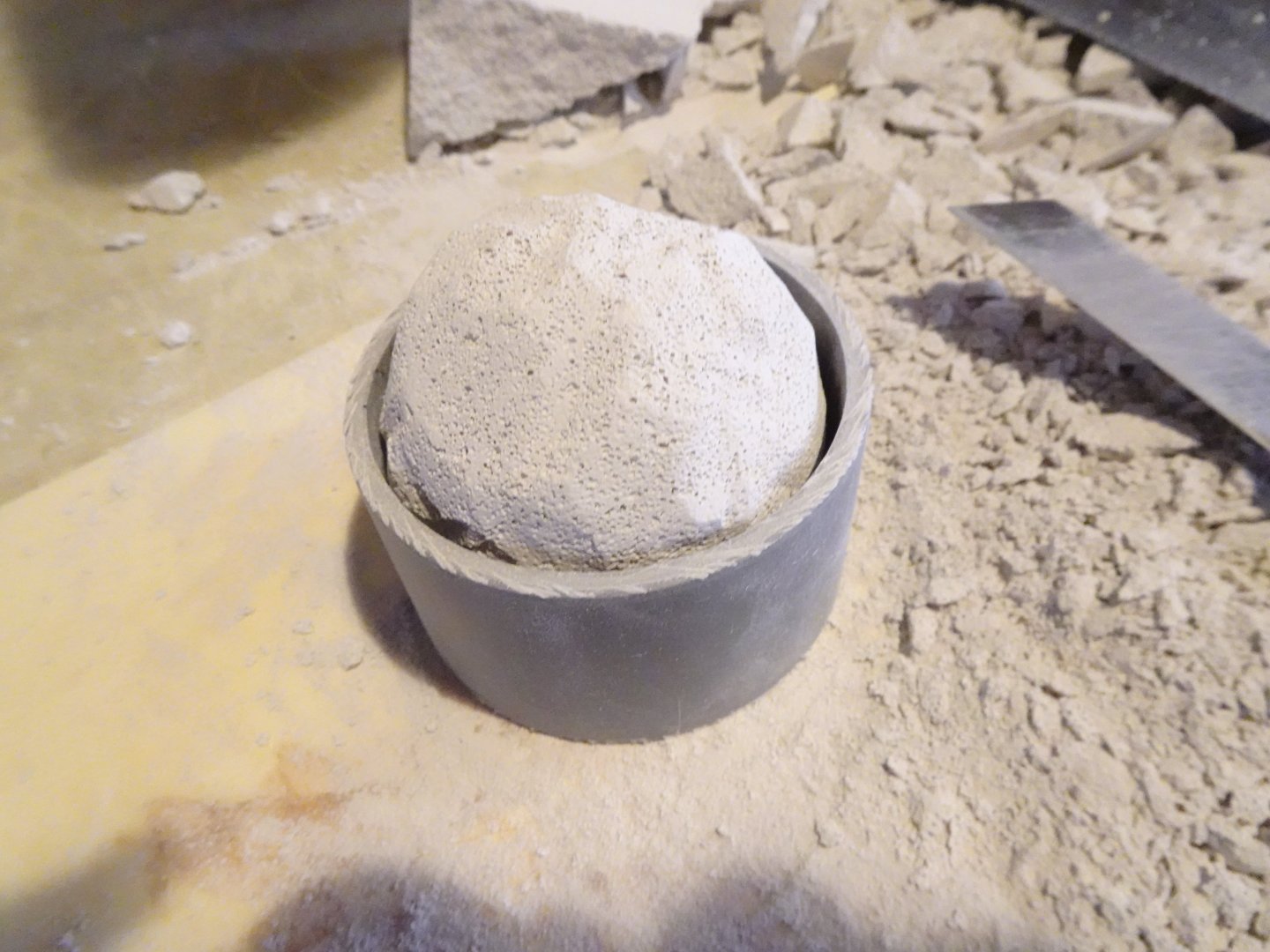
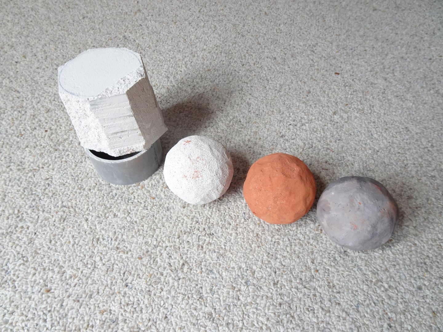
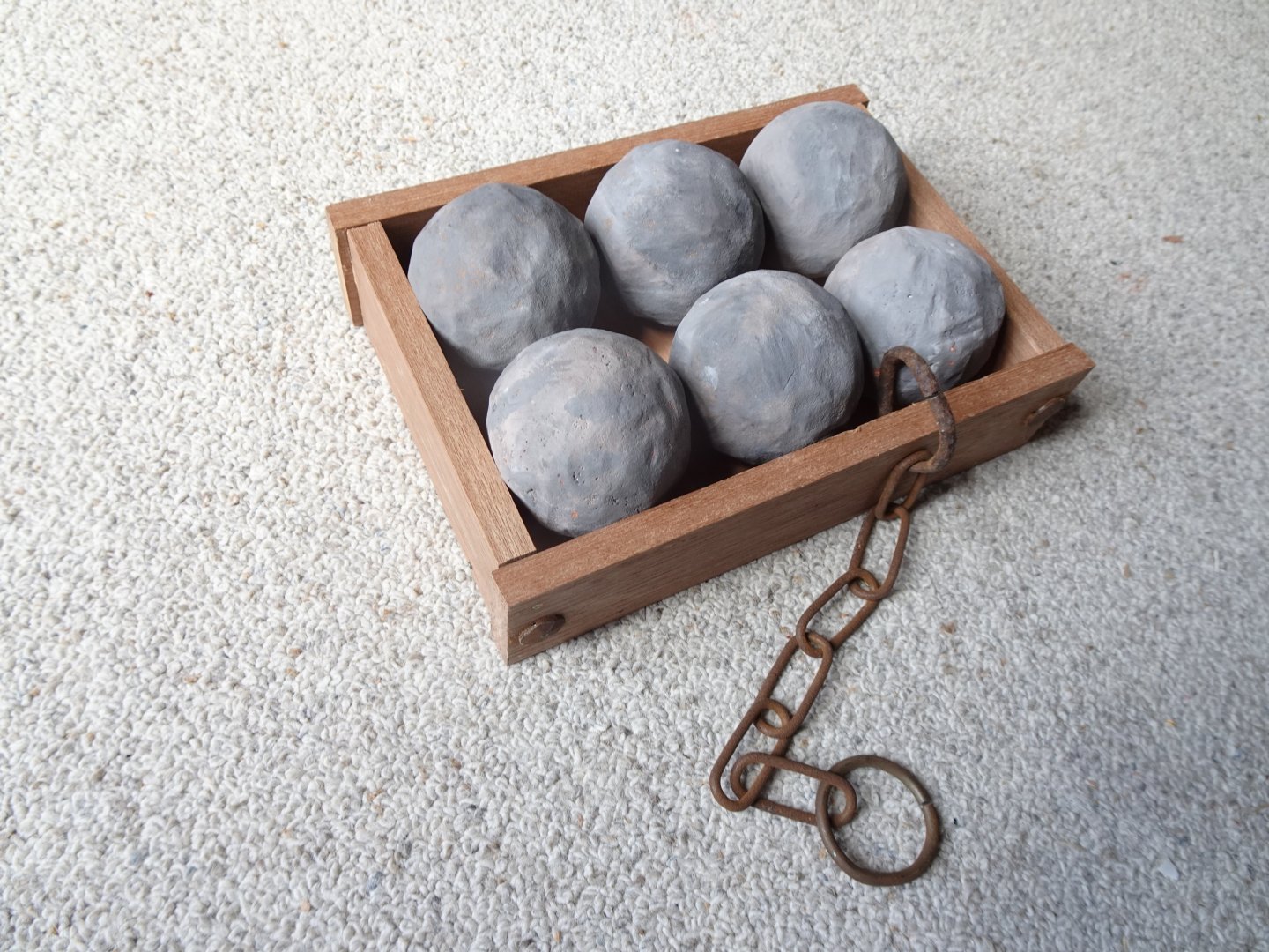
The cannonballs are ready. I made them out of aerated concrete. The photo shows how the process went. A block was sawn out and touched up with a box cutter. The bullet had to fit exactly in a mold that has the diameter of the barrel. Then I filled the holes in the concrete with a filler and they were painted in the right color. Next to the cannon there will be a wooden tray with six cannonballs in it. To prevent anyone from taking them, they are screwed into the bottom of the box from the bottom. Attached to the barge is a chain that will soon be attached to the cannon so that no one can take the barge in its entirety. In reality, such a granite bullet would weigh about 500 grams. The carpenter is still working on the wooden carriage. We are waiting for a few parts that a local blacksmith is making.


- 23 replies
-
- 13
-
-
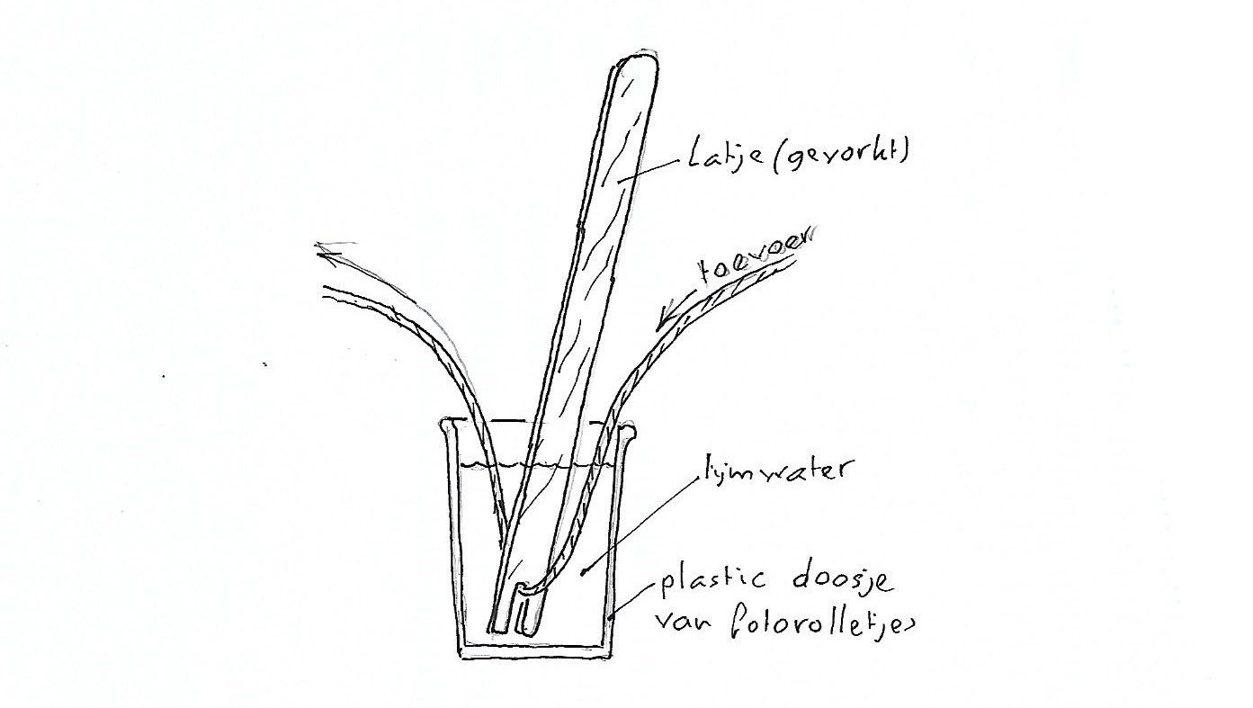
For all rigging I make, I only use rope that does not contain plastic. This rope can be provided very well with highly diluted wood glue. As a result, the fibers of rope do not stand upright, which would attract a lot of dust. In addition, this rope can be easily attached with the help of wood glue. Providing glue in the rope is very easy. A cup with highly diluted wood glue and a stick with a notch at the bottom. The rope is pulled through and is thus provided with glue. Then wipe with your fingers and let it dry In the picture rope without plastic to which glue has been added and not.

-
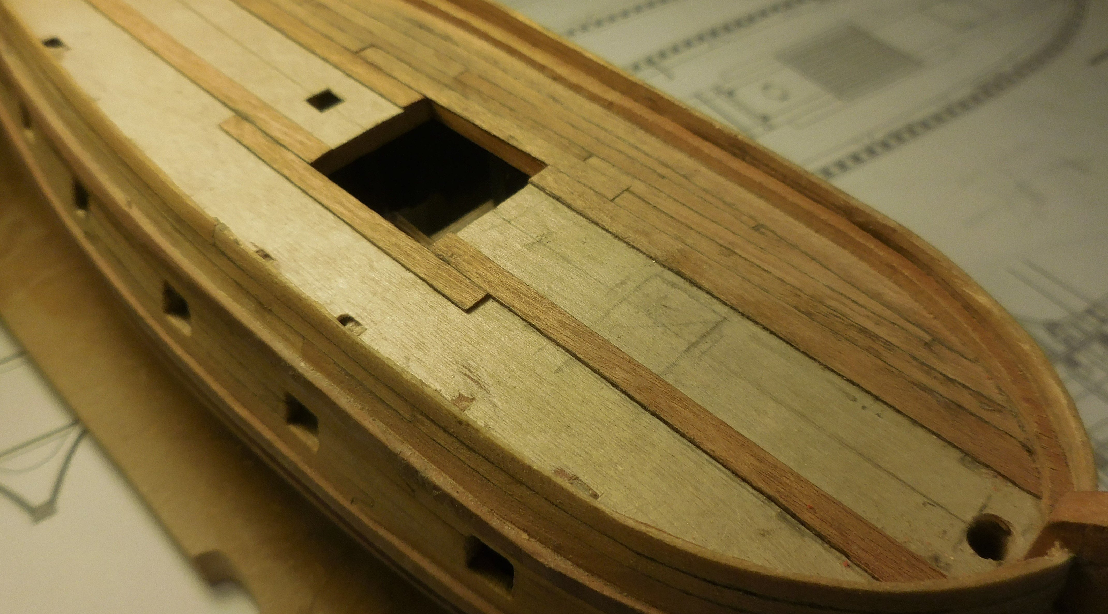
Deck planking
tartane replied to tony1745's topic in Building, Framing, Planking and plating a ships hull and deck
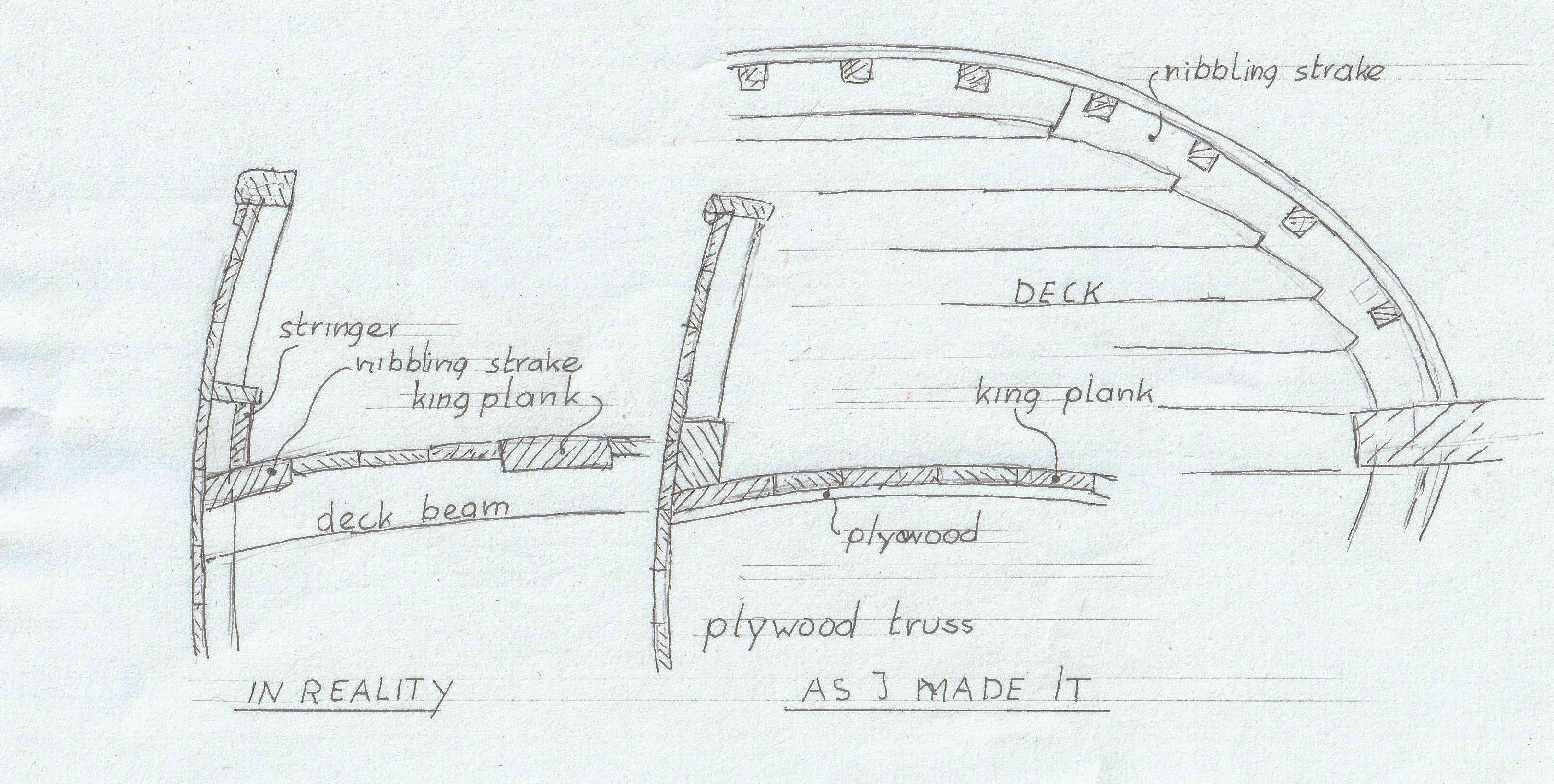
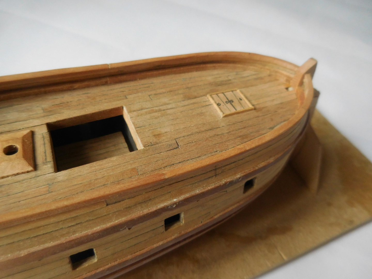
If you are going to apply the planks, it is customary to apply the king planks first. These were thicker and wider planks than the rest of the deck to strengthen the ship's structure. On the deck the six king planks, with the planks in between. The planks don't bend with the shape of the hull, but I made different widths that sometimes interlock. On excavated wrecks you never see nice neat straight planks like we do today. It was not important when a plank tapered as also can be seen everywhere in floors of old buildings in those days, and then often very wide. The tree from which they sawed the planks had not the same thickness everywhere. Constant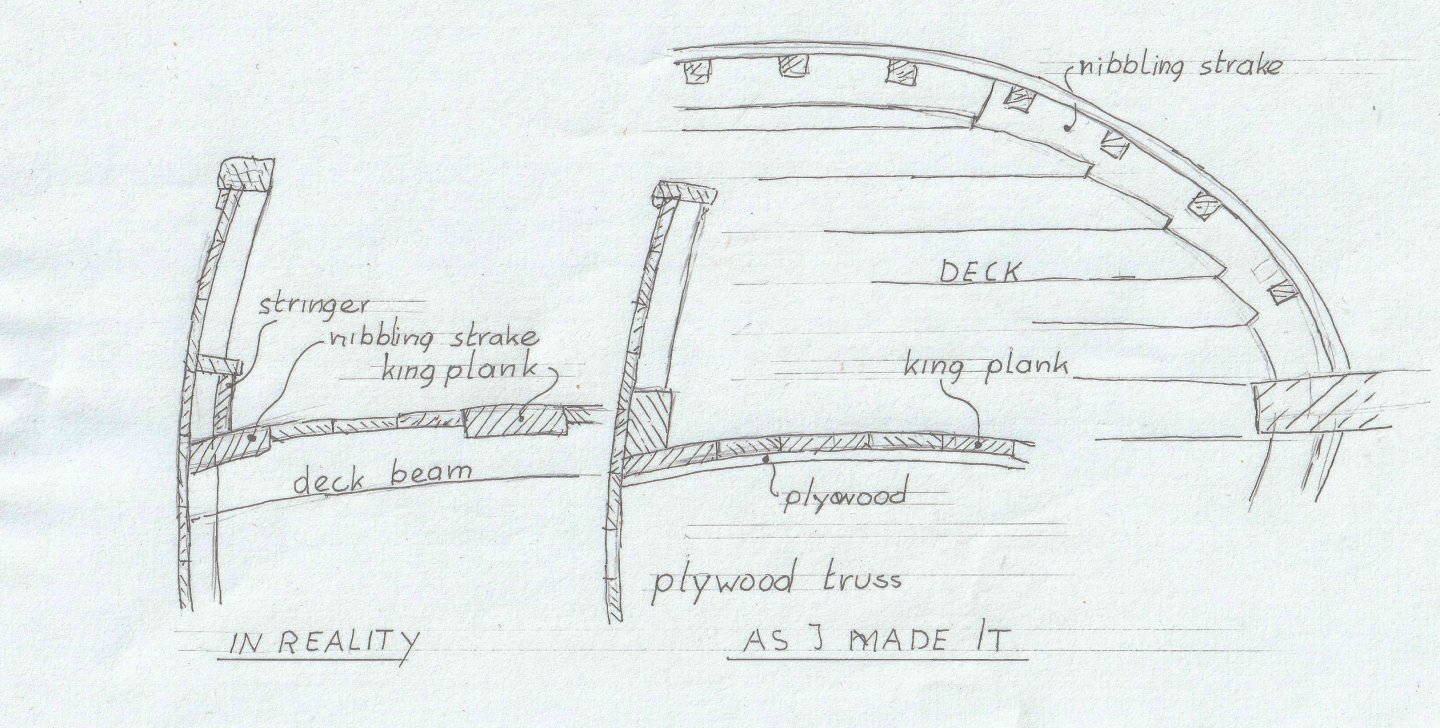

-
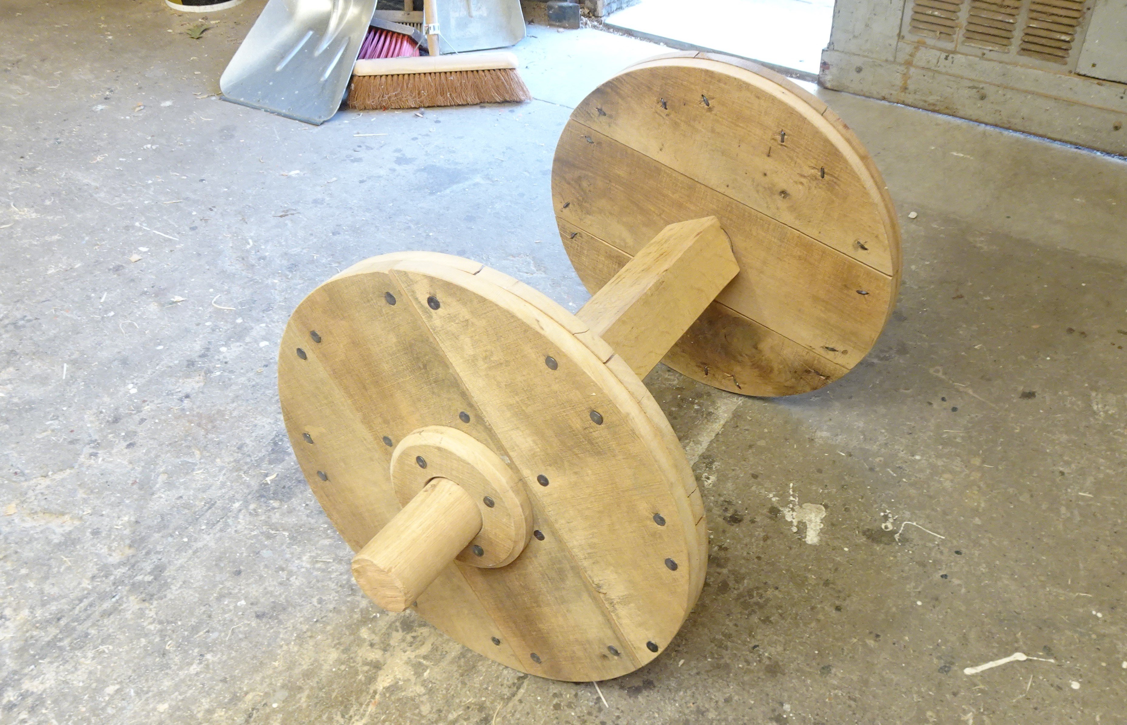
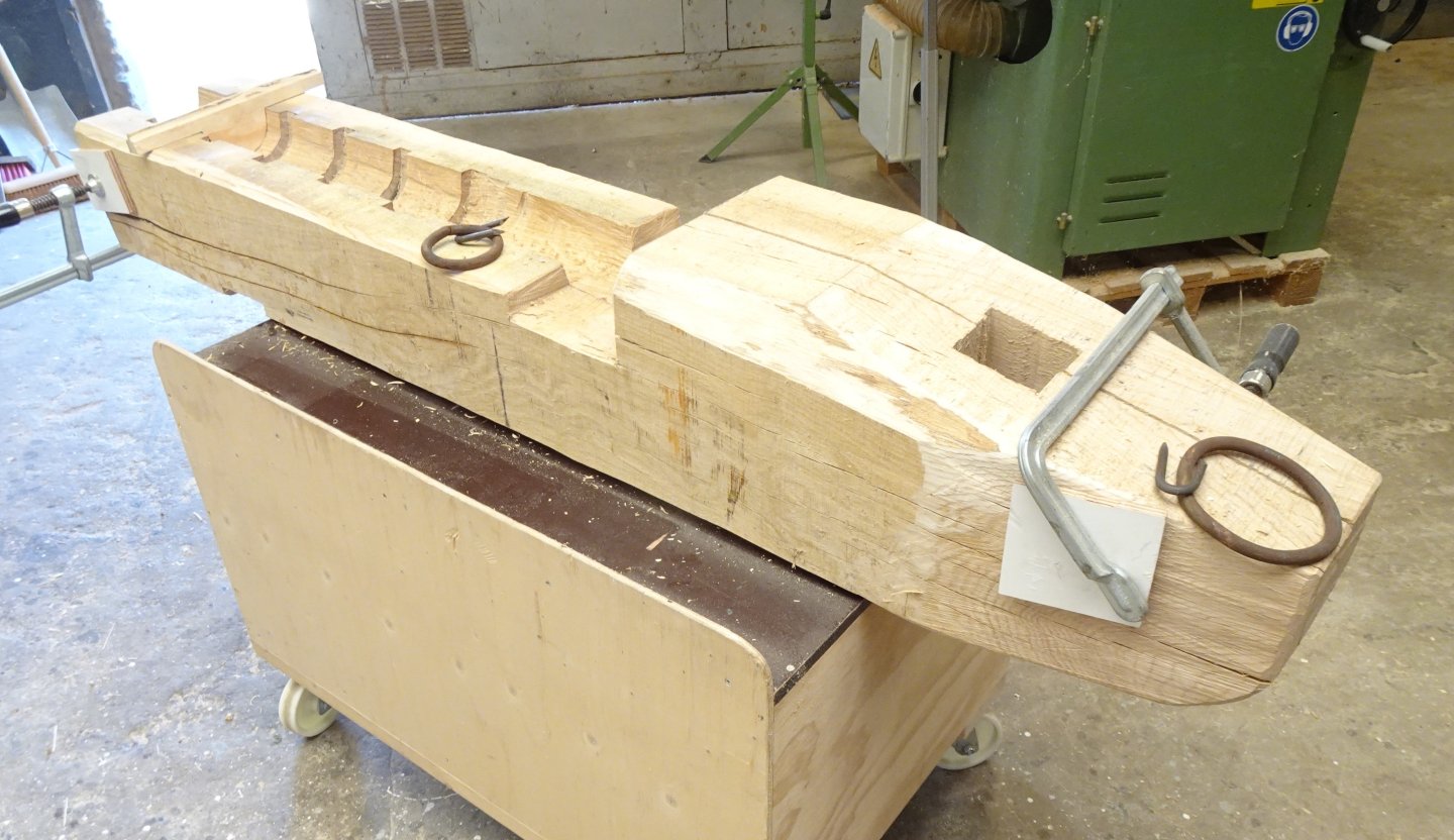
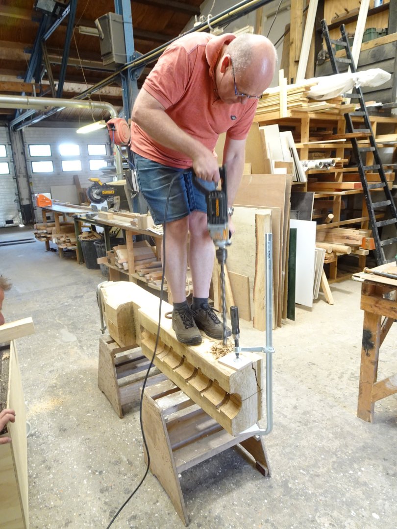
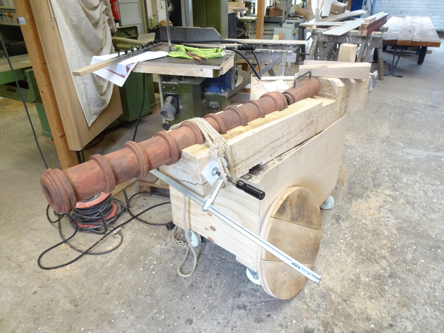
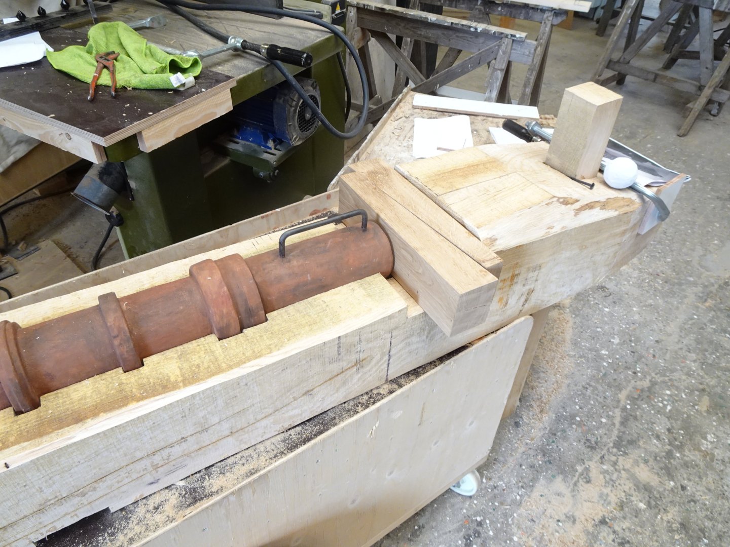
5 The gun carriage is made in a carpenter’s workshop. The medieval Dutch name was "lade" (drawer). It is carved out of an oak tree trunk. The barrel is then placed in a semi-circular floor in which the spaces for the rings are also saved. That way, the barrel couldn't move on a shot, the rings stopped it. As can be seen on many old depictions and also on the recovered cannons of the Mary Rose, the barrel was tied to the carriage with rope. In this way, the gun could be taken apart and transported on a campaign. The wheels could also be removed. Behind the breech the wedges. In this way, the breech could be clamped into the back of the barrel. The carpenter warned me that the carriage would be very heavy. I did the math and indeed it would weigh about 650 kilos. Too heavy to carry him up the stairs in the tower to the place where he will stand. We decided that he would cut the carriage in the lenget into two parts. That sounds crazy, but I can imagine that this was also done in the 15th century to facilitate transport. The two parts are then attached to each other by large bolts fitted with wedges. Behind the wedges a white ball, that's the cannonball. I carved it out of a slab of aerated concrete. In reality, it was natural granite or something like that. The ball still has to be provided with the correct color. In granite, the bullet would weigh about 500 grams, so a pound. Constant

- 23 replies
-
- 12
-
-
-
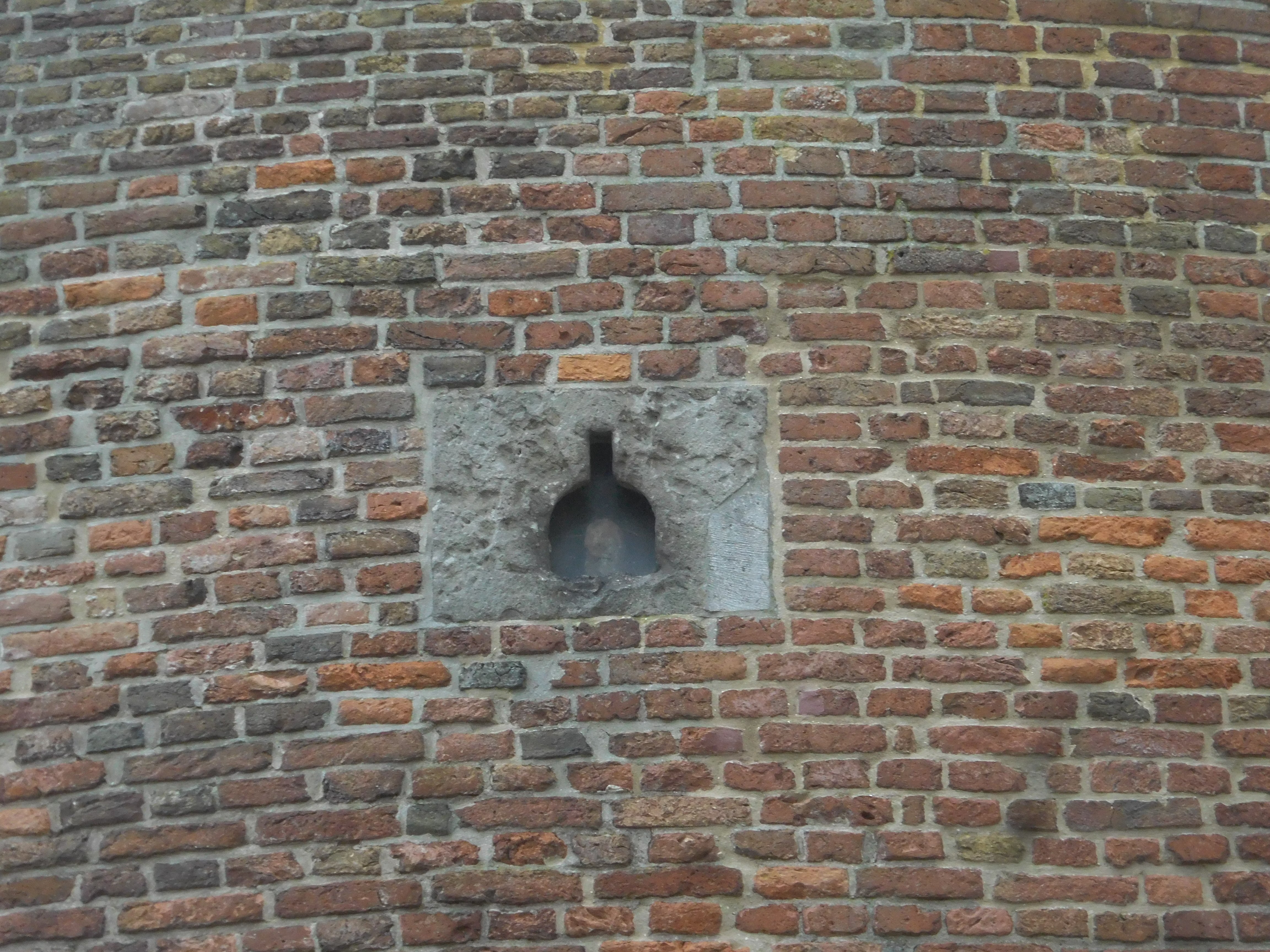
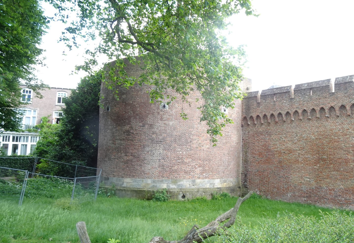
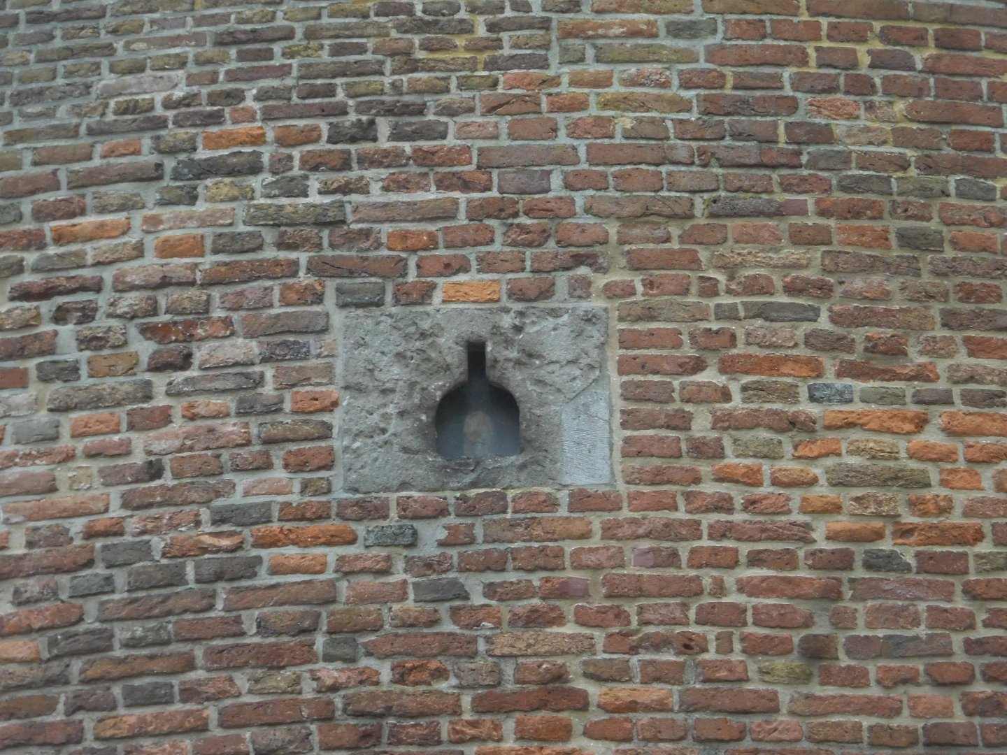
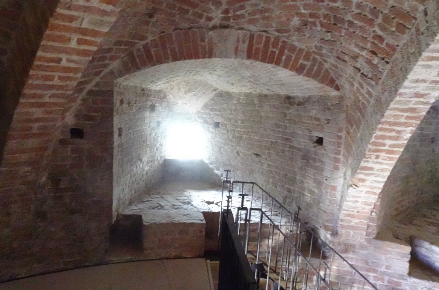
4 The Burgundian Tower in Zutphen, the final residence for the cannon. It was built in 1457 because of the threat of war by the Burgundian Empire. The building has the floor plan of a horseshoe with a maximum wall thickness of four meters. In that wall there are three gun emplacements on the ground floor and five on the first floor. Below were heavier cannons. This cannon will be placed on the first floor in one of the gun emplacements. Not all gun emplacements had cannons. In the event of a threat, the cannons could easily be moved inside the building. This also must have happened to the cannons on ships. The many gun ports on Willem Barentz's ship will not all have been equipped with cannons. If you have 14 openings and there are 16 people on that ship, it's already clear A gun gate of the first floor. The gun emplacement for the cannon I am building. The floor plan of the floor, with the five configurations. This cannon will soon be placed in place A. After the renovation, that place will be accessible by stairs, the others will not. The museum is scheduled to be completed by July 13 of this year. plattegrond.tif plattegrond.tif
- 23 replies
-
- 10
-
-
Roter Löwe 1597 by Ondras71
tartane replied to Ondras71's topic in - Build logs for subjects built 1501 - 1750
Foot ropes. There was a question about the foot ropes. They were not depicted from before the year 1600. At the end of the 16th century, many inventions were made in the field of shipbuilding. One of those things was the use of foot ropes. Before that time they were usually not there because the two main yards of the lower sails were lowered on the deck. There the sails were stowed and then the yards were hoisted again. The sails could then be lowered from above. In the Netherlands, the railing had long time the name "rahout" (ra = yard, hout = wood). Which also indicates that the yards were lowered on it. Barentz's ship from around 1595 did not have those footropes either, which was clearly visible in prints from that time. Constant -
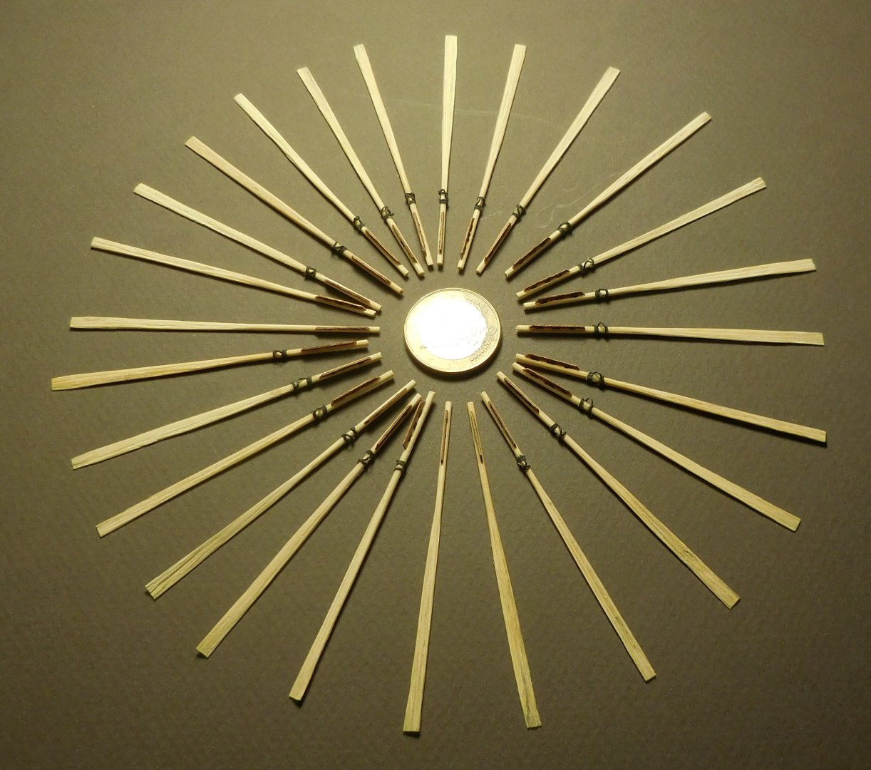
Of course, everyone is allowed to experiment. After some unsuccessful attempts, I am very satisfied with the result I achieved and I have applied it to my models several times. It took me a while to find the right thickness of the cocktail sticks in a supermarket. I had to have 1 mm thick and that appears to exist. The hammering must be done carefully, as soon as the wood starts to split, stop for a while and provide with glue. After drying, continue again. Constant
-
The cocktail sticks are not bamboo, that will not work. To make fine oars by hammering you have to do some practice. Constant


-kopie.JPG.afbb05c2c042d0b78cb0e05156e8f48b.JPG)
-kopie.JPG.540fea2311a563d15b1fd4b8b07fdd54.JPG)
-kopie.JPG.77d13e1fb0dc2ea4299f687caa568958.JPG)