HOLIDAY DONATION DRIVE - SUPPORT MSW - DO YOUR PART TO KEEP THIS GREAT FORUM GOING! (Only 20 donations so far - C'mon guys!)
×


tartane
-
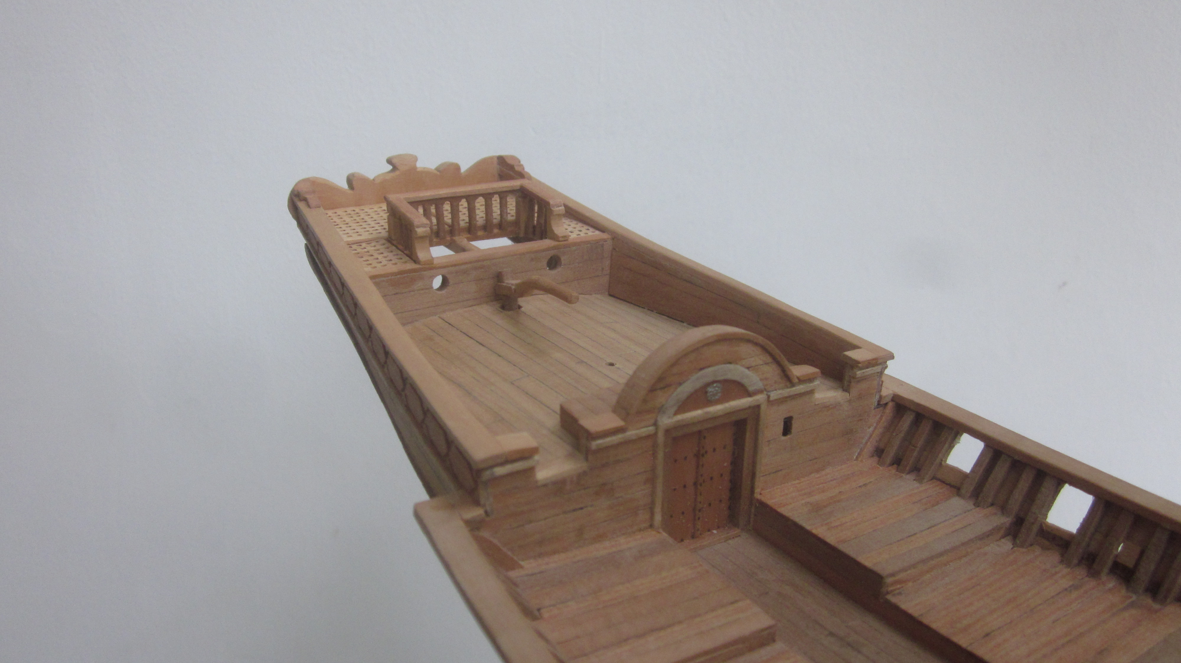
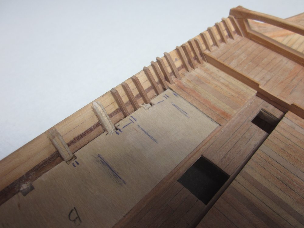
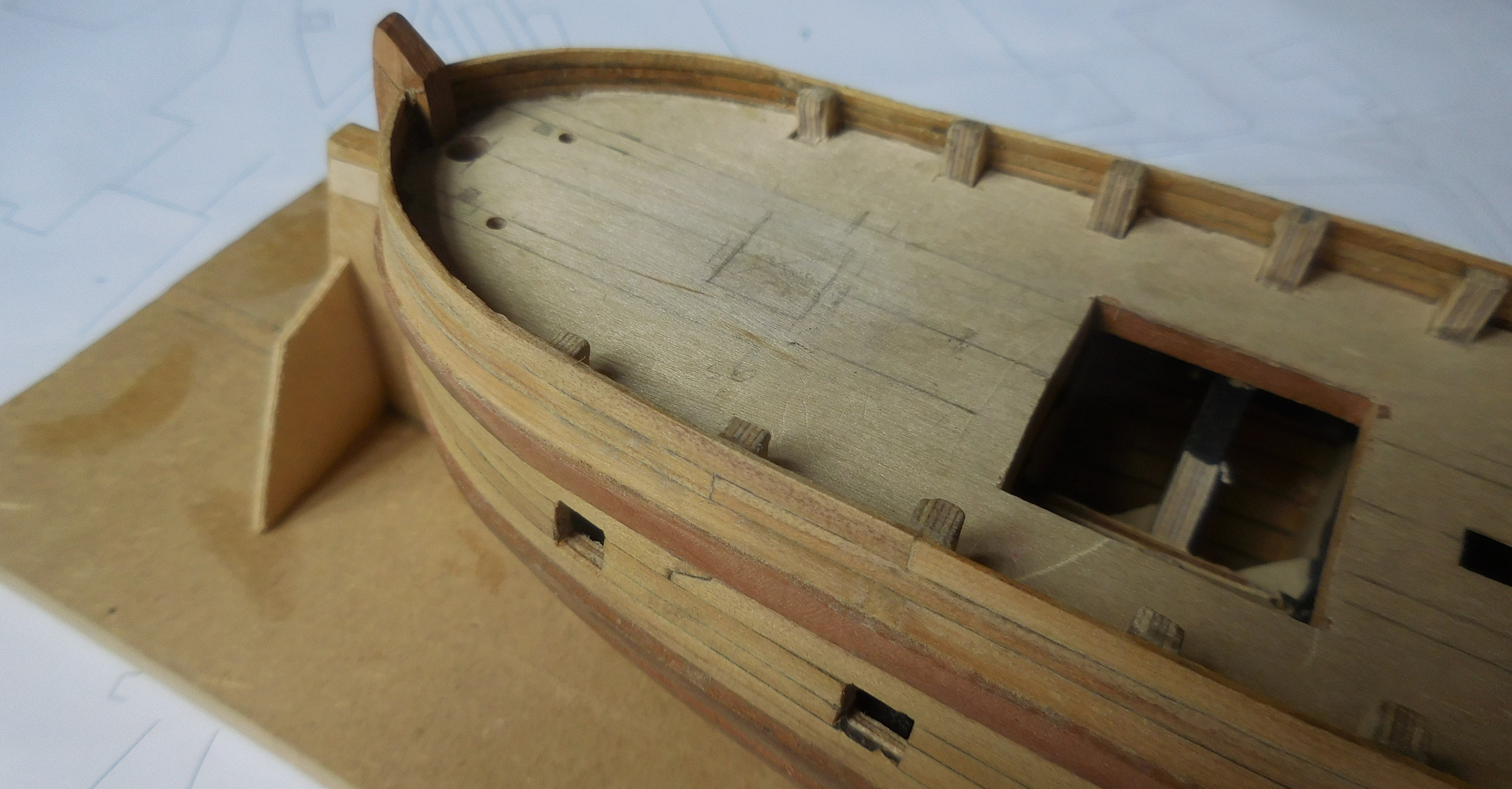
Posts
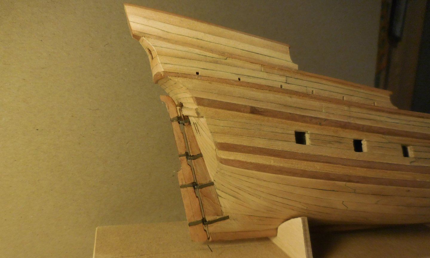
127 -
Joined
-
Last visited
Content Type
Profiles
Forums
Gallery
Events
Everything posted by tartane
-
Patric, To find out as much as possible, I think you have to divide the images that exist into two categories. The first is the collection of images depicting the ships actually sailing around, i.e. in the 16th century. The second is the collection of images that were made after the ships disappeared. So those drawings are based on the drawings that were already there and if they were not right, the imagination went further and further. So you shouldn't take that second category seriously I have experienced this clearly in my long-term research on the chebec, a Latin-rigged ship that sailed in the Mediterranean from about the year 1700 to about 1840. The drawings that were made at that time were very correct, and were made by a few draughtsmen who had also sailed on them. But after 1840 there are fanciful depictions of painters who were not familiar with these ships but who sketched a romantic and very exaggerated picture from the existing drawings. This was the reason why models of these ships were suddenly made long after 1840, which also ended up in the maritime museum in Paris. Those models were wrong and can still be seen there. There are curious flaws in it. Unfortunately, manufacturers of construction kits then started measuring those models, so that there are now construction kits on the market that give a completely wrong picture of those ships. There are a lot of things wrong and I never understand why the builders themselves don't see this. This also came up again and again in my research into the cog. If you wish, I would like to help you in this search. I admire your work in details. Constant
-
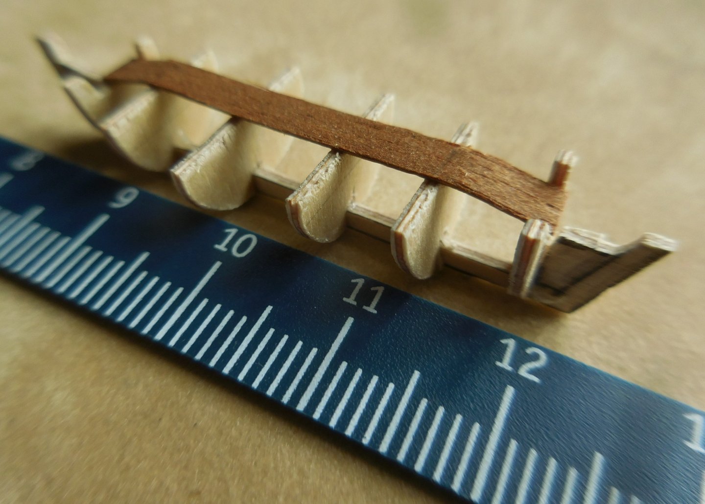
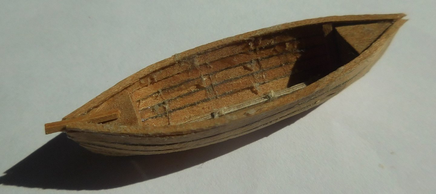
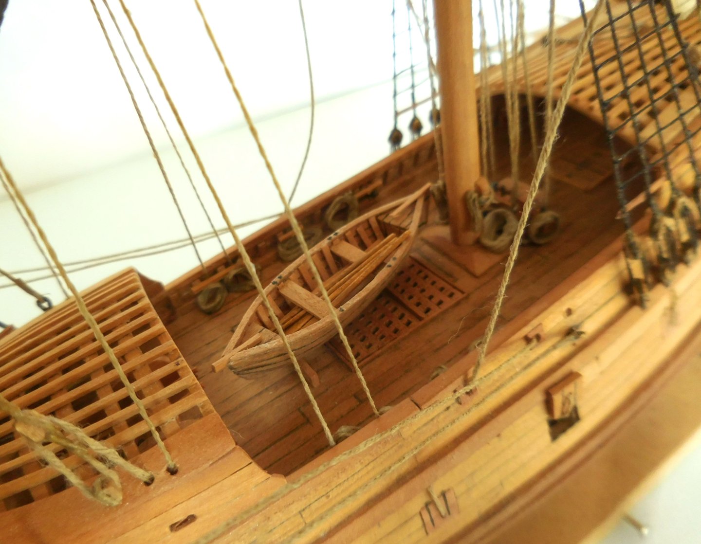
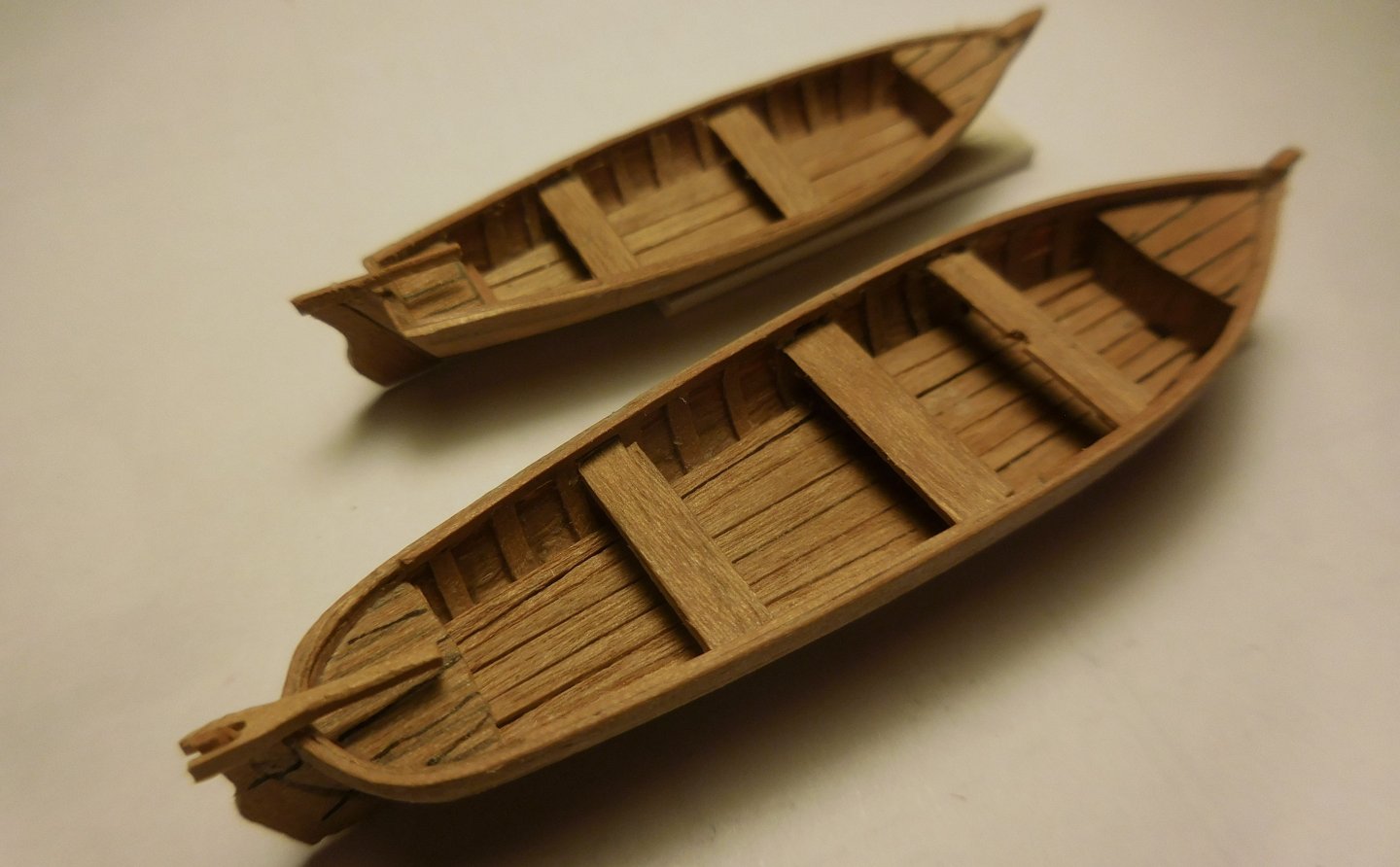
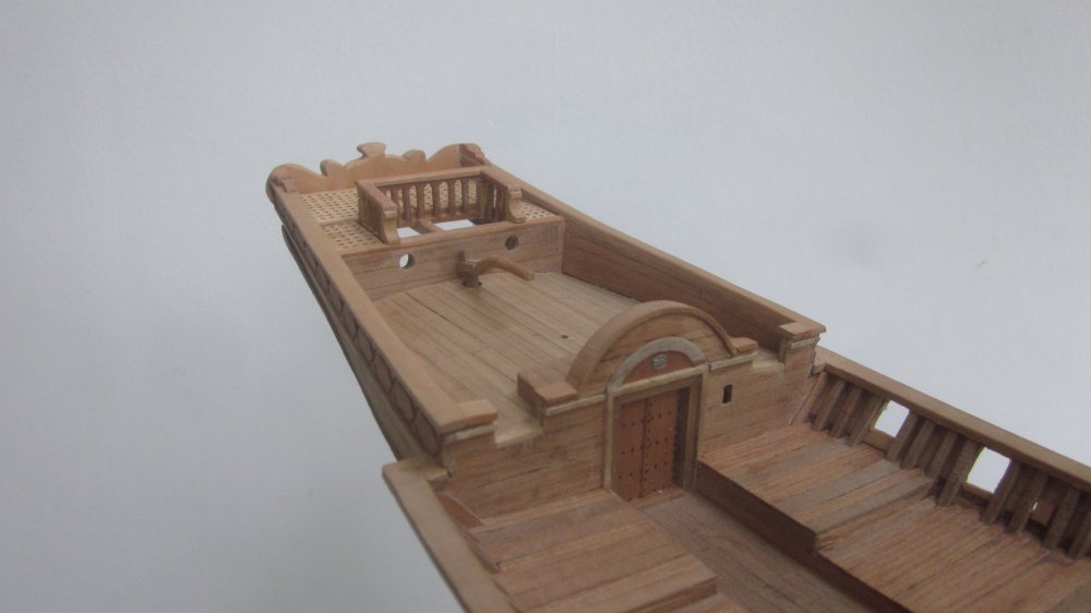
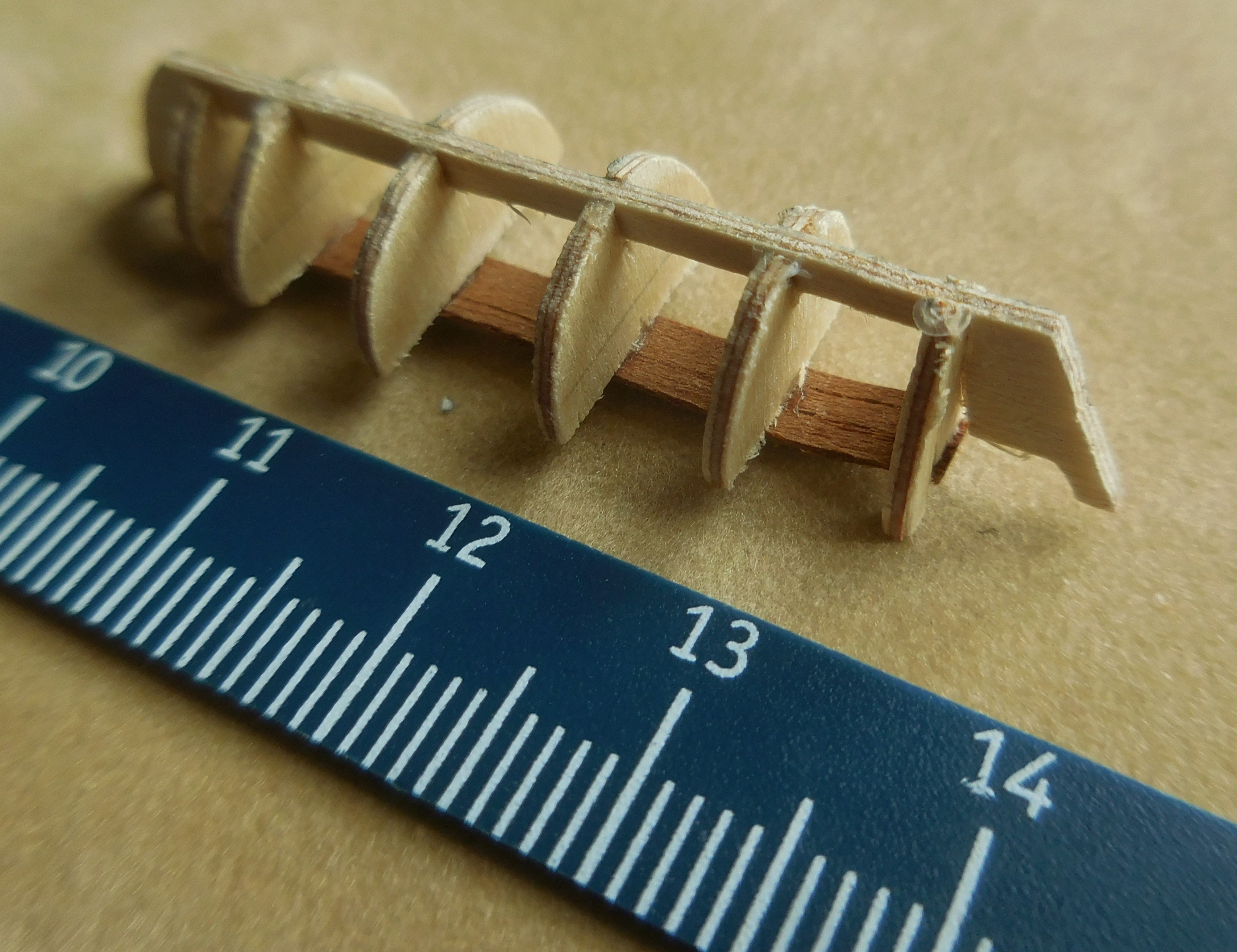
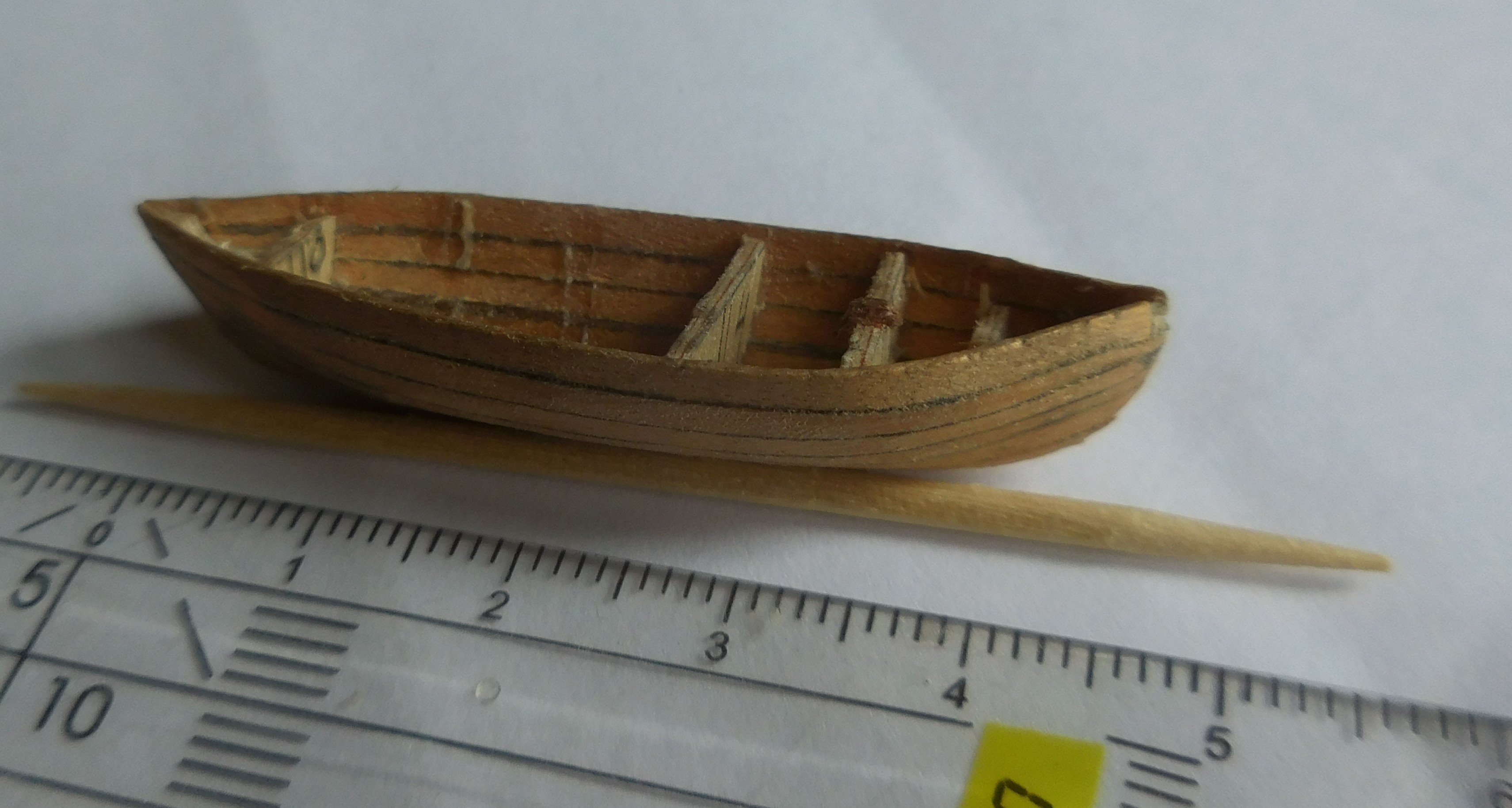
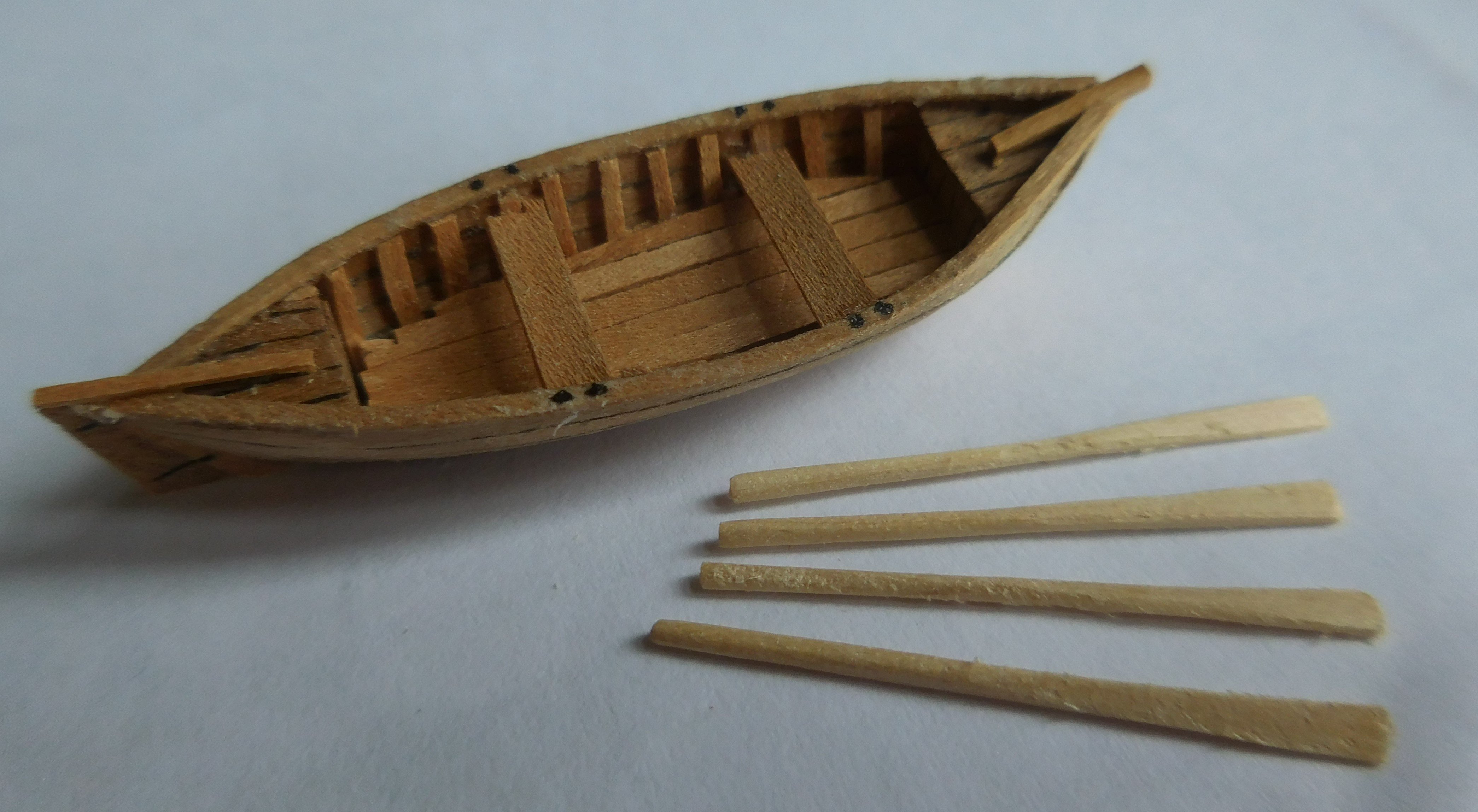
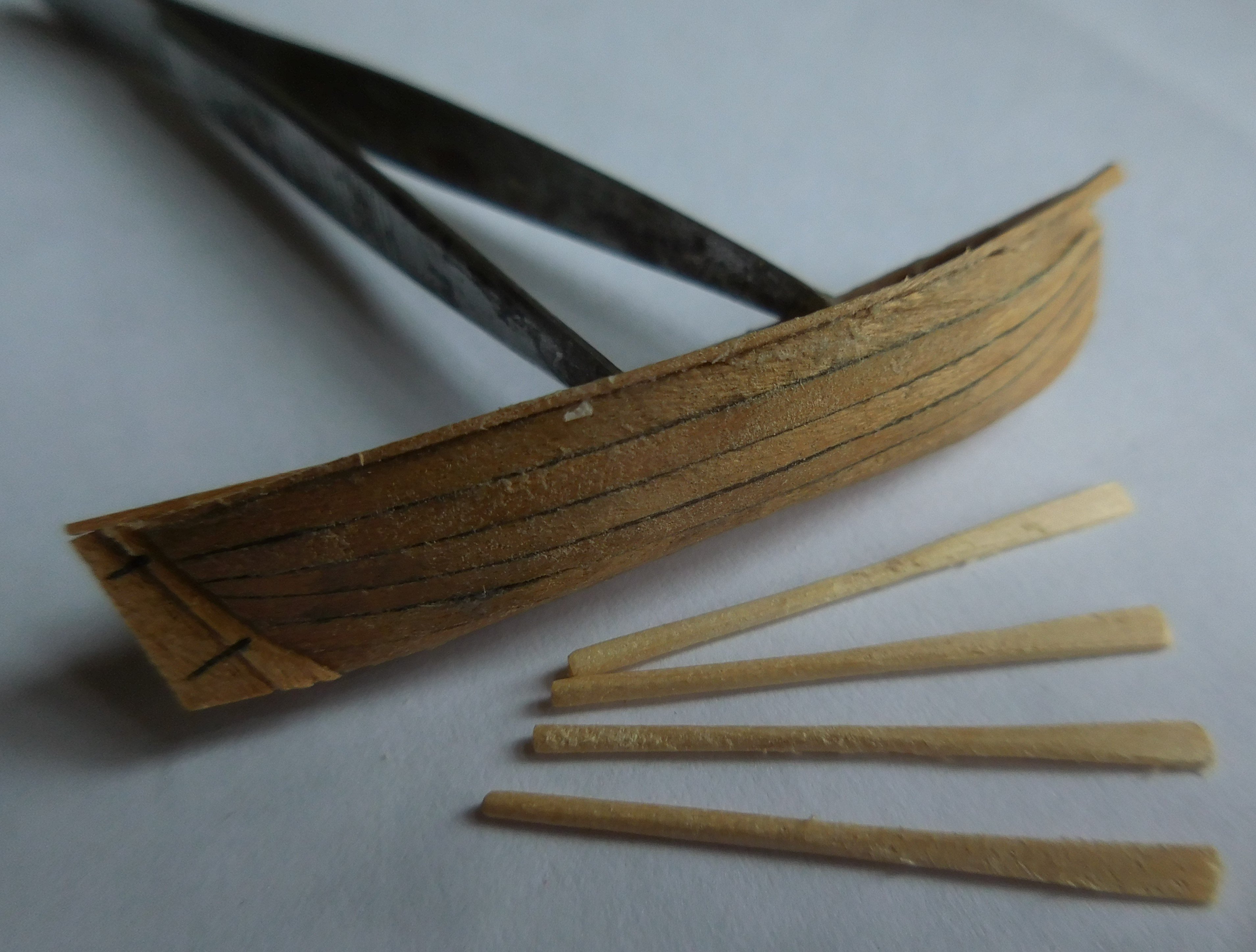
9 The boat. Like most ships at the time, a pinas also had a boat. It is often claimed that these were towed, but on the open sea in stormy weather they could easily be lost. So usually they were on board, and were only put out when necessary. First I made the trusts out of thin plywood and glued it together. The planks were attached to it of thin ash veneer, after which a few trusses of plywood were very carefully removed from it A fore and a rear deck were then put in, and the last plywood trusses disappeared Finally, the real trusses were glued in and the bottom and rowing benches were installed, as well as the rudder. Finally came the oars, made of very thin toothpicks. By flattening the end with a hammer and providing it with glue, the blades could be formed. The boat has a length of 42 mm. After this, it had to be carefully sanded. I have made several boats for other models before, all on the same scale and on the same construction method. The showcase and stand The model is placed in a glass showcase that was made by a company. At the bottom of it I made a stand consisting of perspex discs. For its construction, see my topic: “Making a “wet” stand for your model” march 19 2024.


-
All those images don't convince me. We will have to wait until a wreck is excavated where the fore castle is still visible. At the time that these images were made, it was customary to depict everything more proudly and it was unimportant whether it was correct. See also, for example, the Mataro ship in Rotterdam, where it has been established that it could not sail in that form at all. Constant
-
What I yhink very curious is the enormous height of the fore castle. I can't imagine that a shipbuilder dared to go that high and indeed the ship seems to have tilted as a result. It also catches a huge amount of wind. Isn't the drawing that exists of it a very exaggerated representation of reality? That was often the custom at that time. Wouldn't it be advisable to reconstruct the height to the human scale? So the deck heights do not exceed 170 cm, then with those three decks you get to a height of 510 cm plus the beam thicknesses that were still in between. Then it will be at most 60 cm higher. I would never go higher than 510 cm. But maybe that's also the height you calculated yourself because I don't know the scale exactly. Constant
-
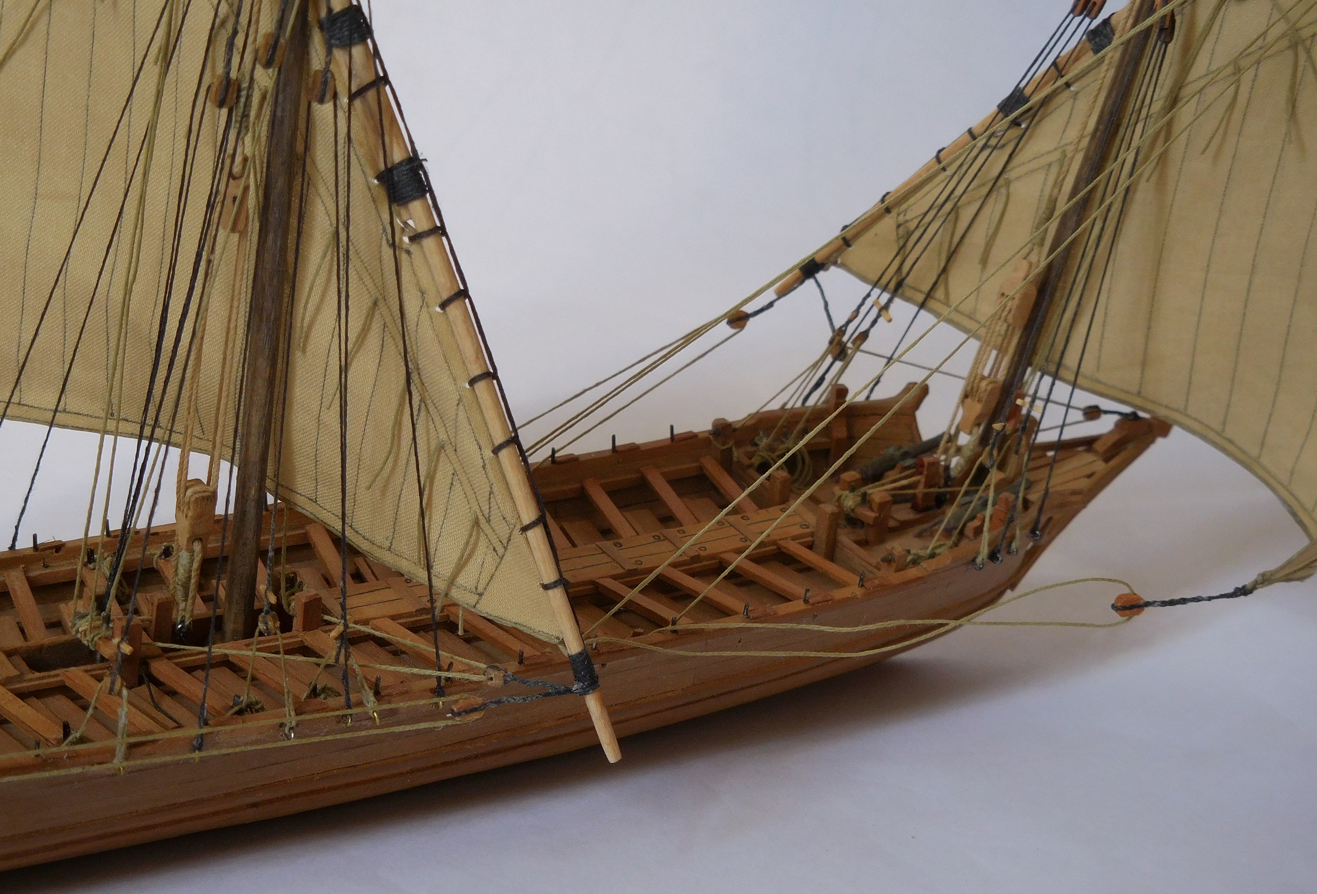
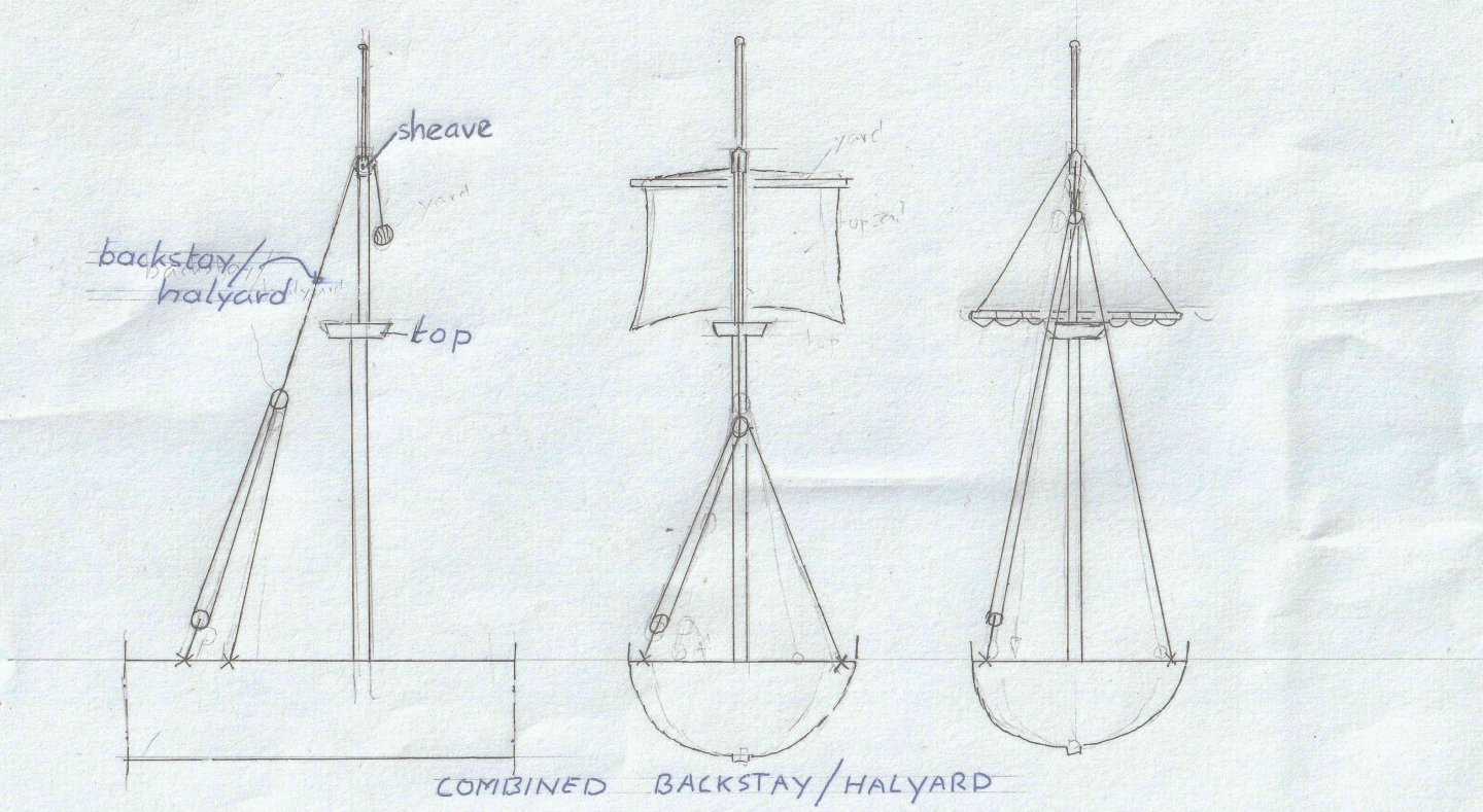
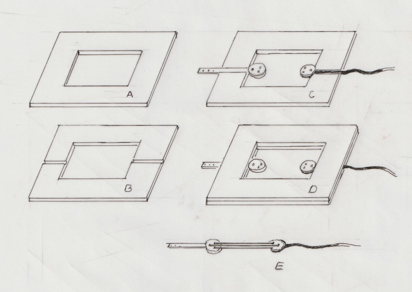
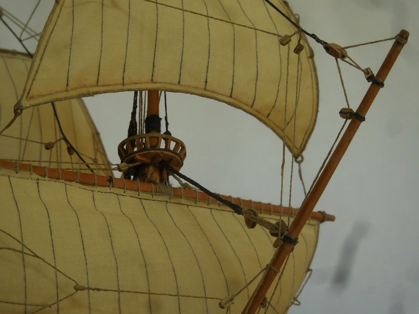
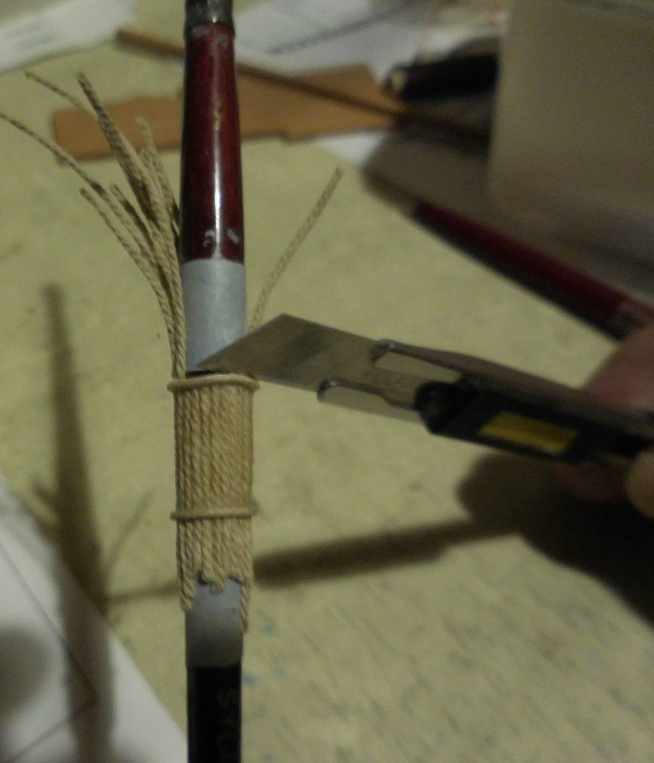
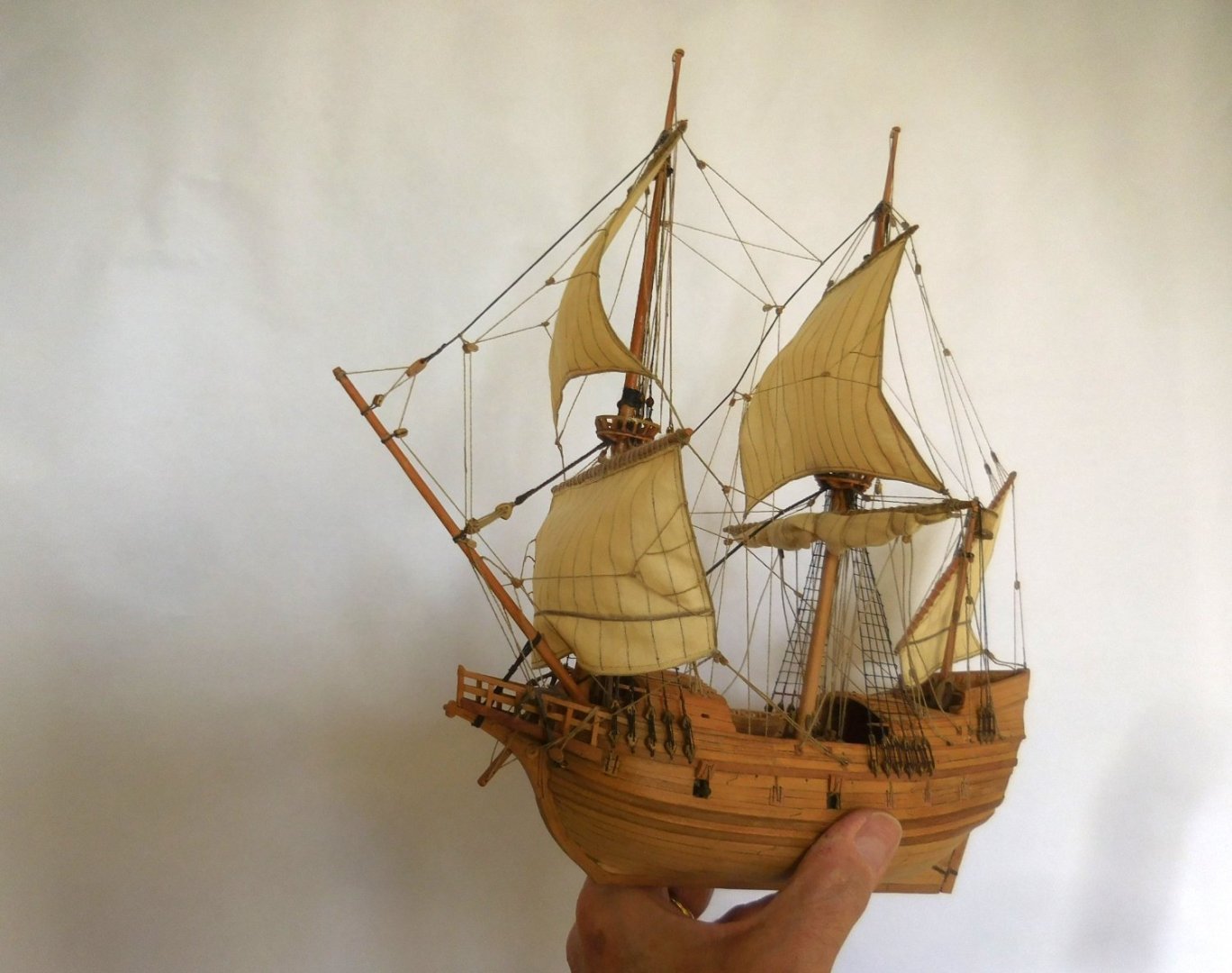
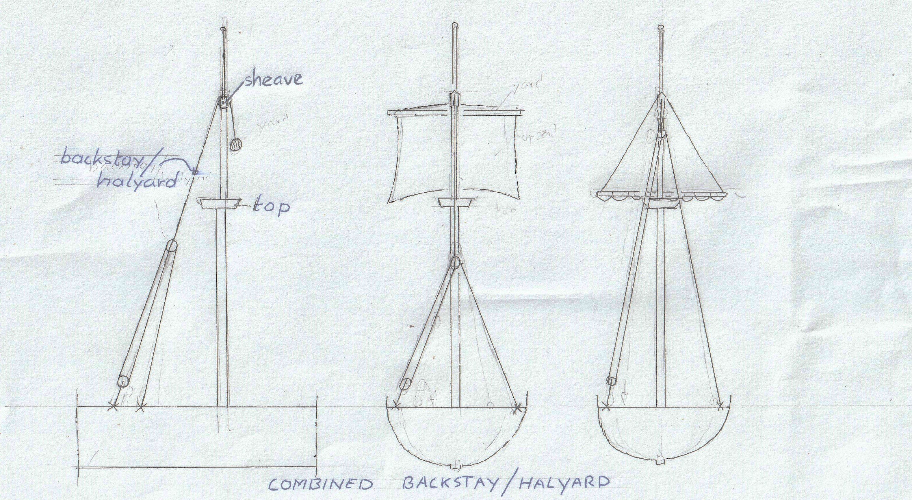
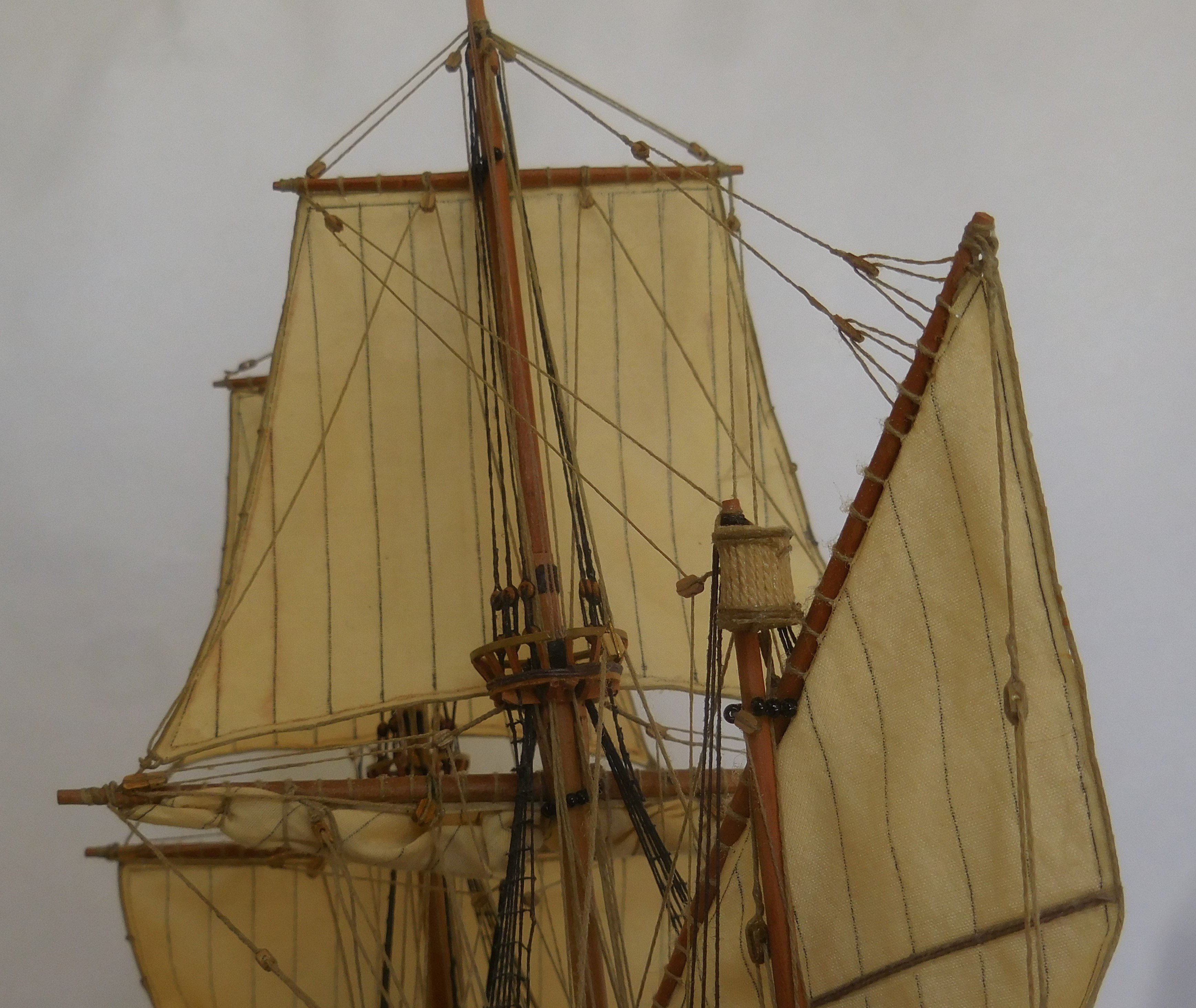
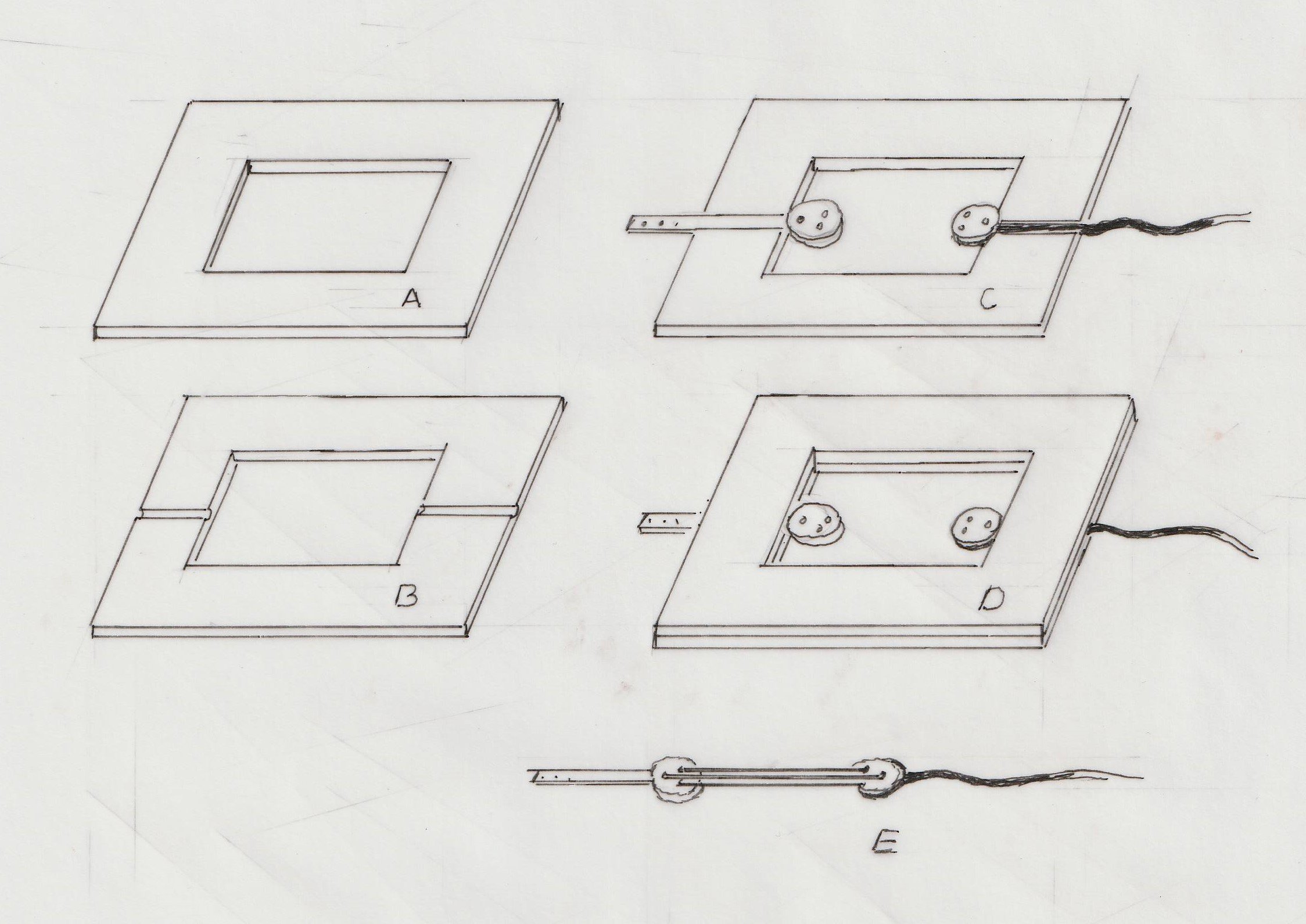
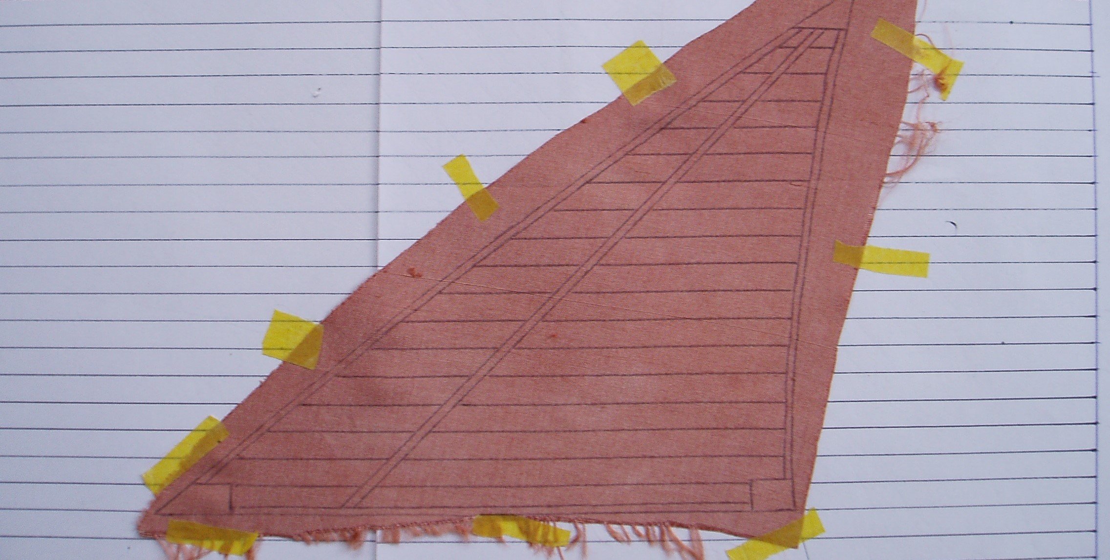
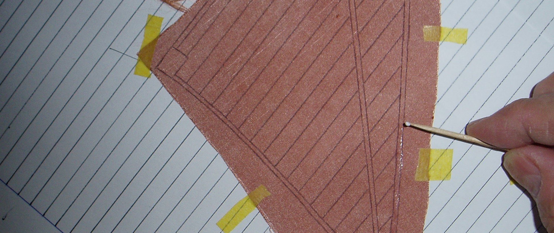
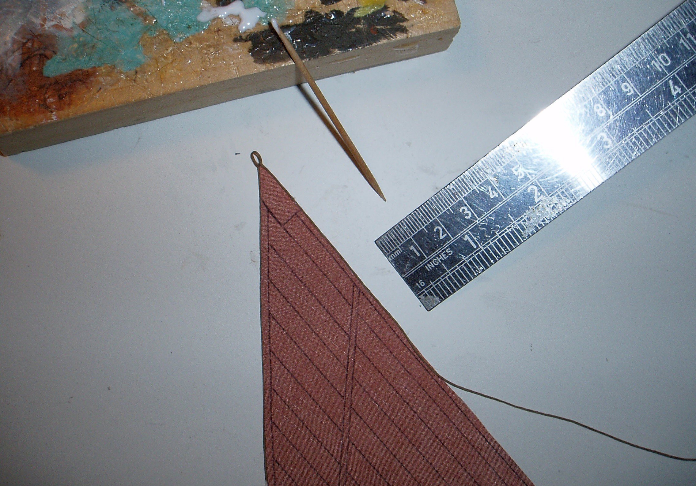
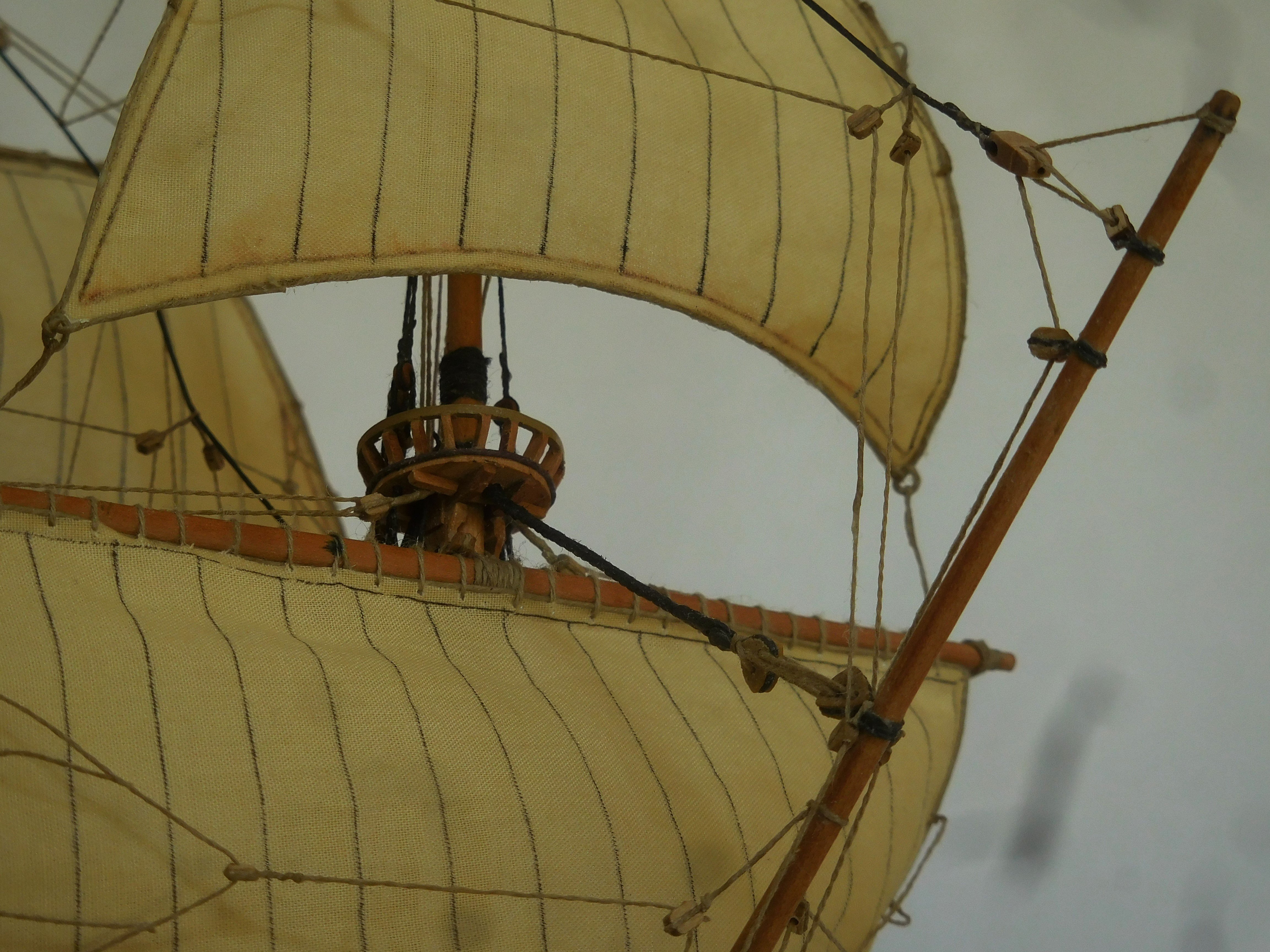
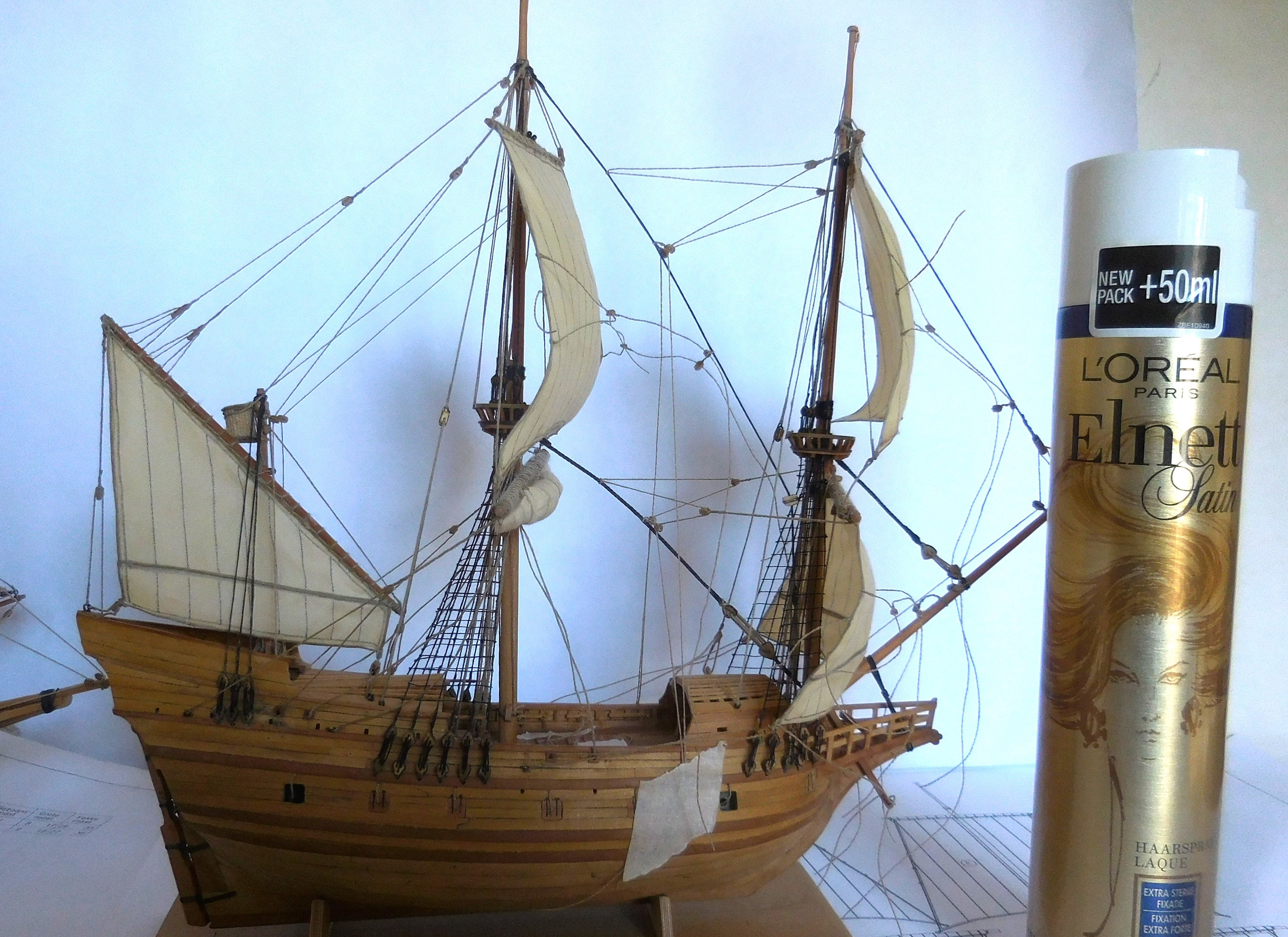
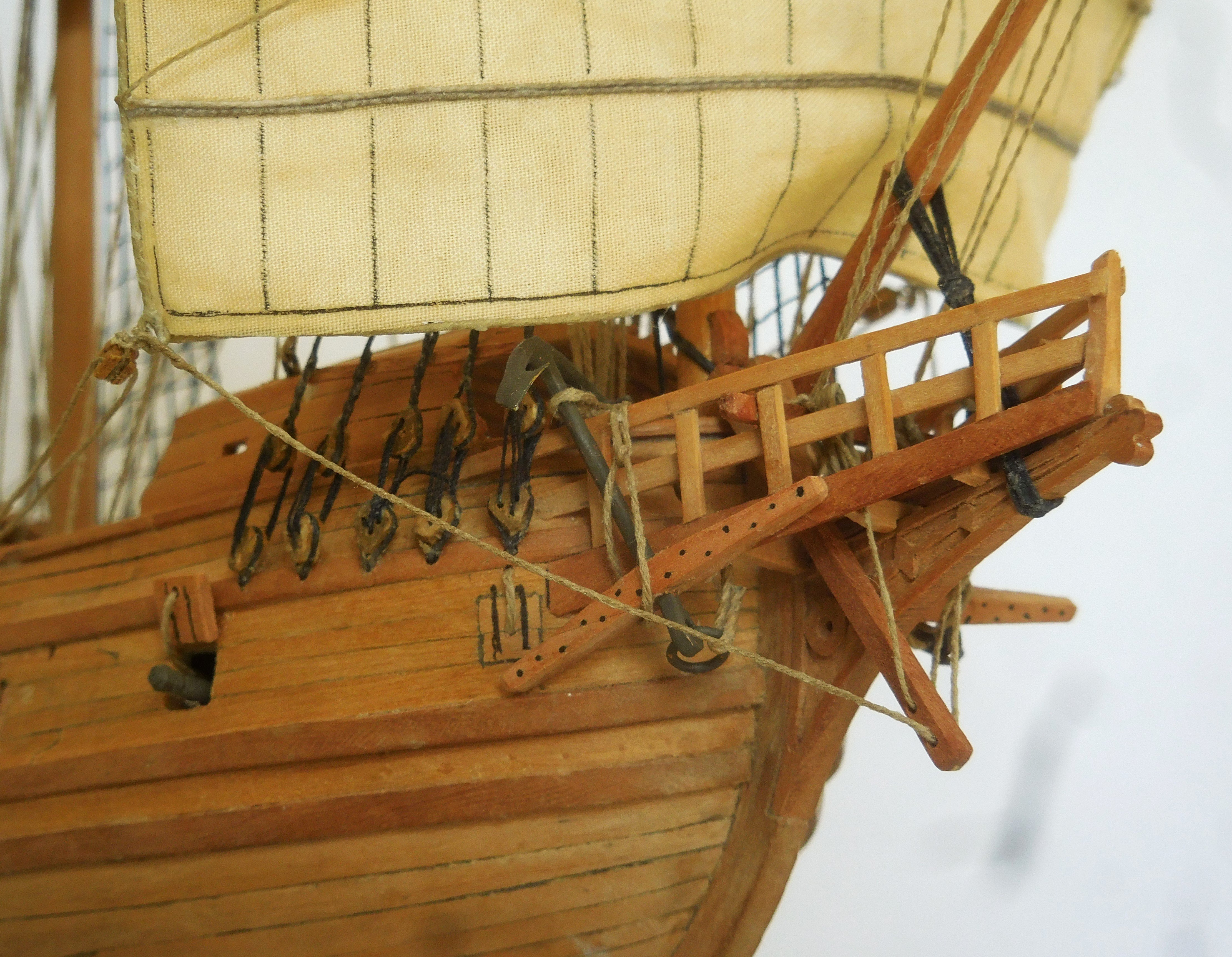
8 The rigging. During rigging, it was a seemingly confusing tangle of wires. This work often caused problems. This is the first square rigged ship I built. The previous ships I made were latin rigged. Their rigging is considerably simpler than the rigging of this ship and is also completely different. The lower yards were lowered onto the railing, the rahout. This was no longer done in the 17th century, where the sails were tied to the yards just below the tops. The upper yards were lowered onto the tops. On the model the mainsail on the mainmast is tied up, which was done at deck height and then the yard was hoisted up to below the top. Since the 17th century, in order to moor the masts at a great height to prevent them from bending forward, the masts have had back stays, which were attached on the deck. On this ship, the back stays and the halyards for hoisting the topyards are still combined into one rope. Exactly how this worked is not entirely clear. Ab Hoving left it entirely up to me to find a solution. The topyards were hoisted from the top. This is only possible with a haliard and a sheave in the mast. The halyard was fitted with a block and tacle was attached to port and starboard. Once the yard was hoisted, it automatically became a backstay, a rope that held the top of the mast in place at the back to prevent it from bending. So this is a possibility as it could have been made. On large ships after 1600 it can be seen that there were ratlines on the shrouds everywhere. On ships before 1600, there are only four shrouds with ratlines. Only from the deck to the tops of the foremast and mainmast. This can also be seen in the drawings of Gerrit de Veer. These were attached about 40 cm apart. I glued the ratlines to the shrouds with superglue. In fact, all the ropes on the model were far too thin compared to the rope available in model shops. This meant that the available rope had to be split again and again. This also meant that different thicknesses of rope had to be made. I only used rope that had absolutely no plastic in it. This rope is not stretchable and can also be glued very well with wood glue. In addition, each piece of rope was pre-glued to prevent the fibers of the rope from sticking out and thus not attracting dust. The running rigging was made of brown rope, the standing rigging was made black (tarred). The smallest commercially available blocks had to be purchased. It became a search on the internet for the various suppliers. A number of blocks had to be made even smaller, which could be done by cutting and filing. The smallest blocks are located in the tops of the masts, in fact the blocks that were needed to hoist the flags. Some blocks were composed like the blocks at the ends of the yards. These were created after gluing two blocks together. Some of the blocks had a somewhat different shape, like the lift at the top of the mizzen yard. The first blocks from the tops that are needed for the lifts of the yards are also different. They had to be made manually from a piece of wood. I avoided to place round deadeyes. At that time, the deadeyes were triangular in shape. I filed round deadeyes in the right shape. Making deadeyes and lanyards Usually on shipmodels the deadeyes and lanyards are made when the lower deadeyes are already mounted. Because the scale of this ship is very small, I made the deadeyes and lanyards separately with the accompanying shrouds. I designed the following method: I sawed two equal sheets of plywood 2 mm thick with the same rectangular hole in the middle (A and B). The length of this hole is the length that corresponds to the total size of deadeyes with lanyards. In the sheed B, two grooves come next to each other. The chain plate will be attached to one deadeye and the shroud will be attached to a second deadeye. Both blocks are now placed in the grooves, picture C. On top of that comes the sheet without grooves, picture D. Both plates can now temporarily attached to each other with tape. Inside the opening, the threading can now begin and be secured. After removing the tape, the ready-made deadeyes with lanyards appear (E). They can now be attached to the model. There are 38 deadeyes with lanyards of two different lengths attached to the model. So that requires sawing the plates twice again. This ship was not yet equipped with channels, that only came a few years later. The chain plates, possibly ordinary rope, were attached to the a wale. Here I chose the method of replacing the chain plates with rope. It took quite a bit of effort to get the thin strings through the tiny holes of the blocks. Often these passages still had to be drilled out with very small drills. The end of such a rope was reinforced with some superglue so that a thin sharp needle was created that could easily go through the hole. The sails. The sails were made of cotton that was as thin as possible. It was difficult to get to a fabric store there, so I went to a second hand store and dived between the women's blouses hung there. After some searching, under the hilarity of ladies present, and comparing, I found the thinnest possible white cotton that I was going to use for the sails. The dimensions of the sails were copied from the drawings and coloured The pattern of the strips was applied by means of a Rotring pin. To imitate the bolt-rope on the sails, I glue rope against the side. I always use this method when making the sails of my models. The photo shows how this works (on the sails of a chebec). I use regular wood glue. The edges of the sails are first provided with highly diluted glue, which should not shine after drying. So first make test pieces until the glue is so diluted that the shine is gone. Apply the glue with a toothpick After drying the glue, the outline must be carefully cut out, the glue will prevent the fabric from fraying The pre-glued rope is then glued to it in pieces of about 30 mm by pressing it with a metal plate, for example a steel ruler. See also my website; www.constantwillems.nl After most of the rigging and the sails were attached, I wanted to make a natural bulge of the sails. With a fan I blew the sails into a nice position and then added hairspray with a spray can. After some time I stopped with the fan and the sails remained in a natural position.
.thumb.JPG.0c8b1ee91105688e1cdc9787c3393761.JPG)

-kopie.thumb.JPG.7e095a1306d20b0e14d8842d89bf13c0.JPG)


.thumb.JPG.711b863b39c3b48814ef2807e7782772.JPG)
-
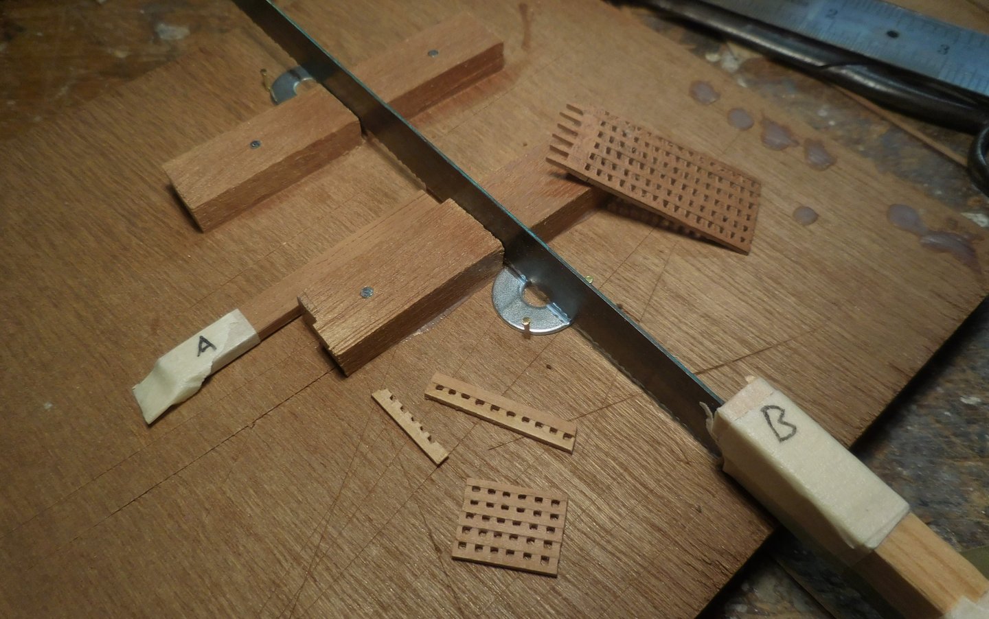
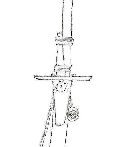
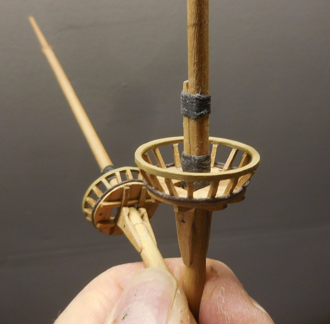
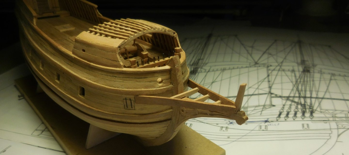
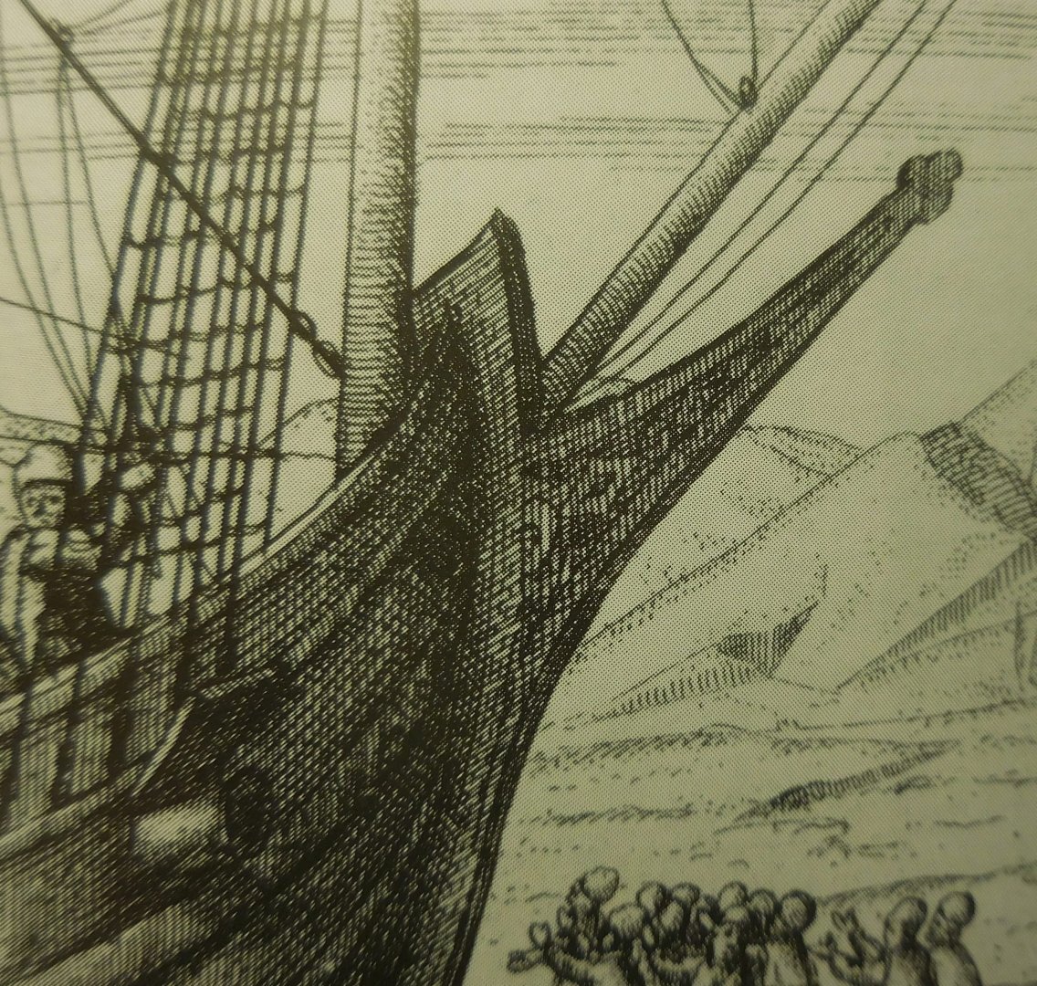
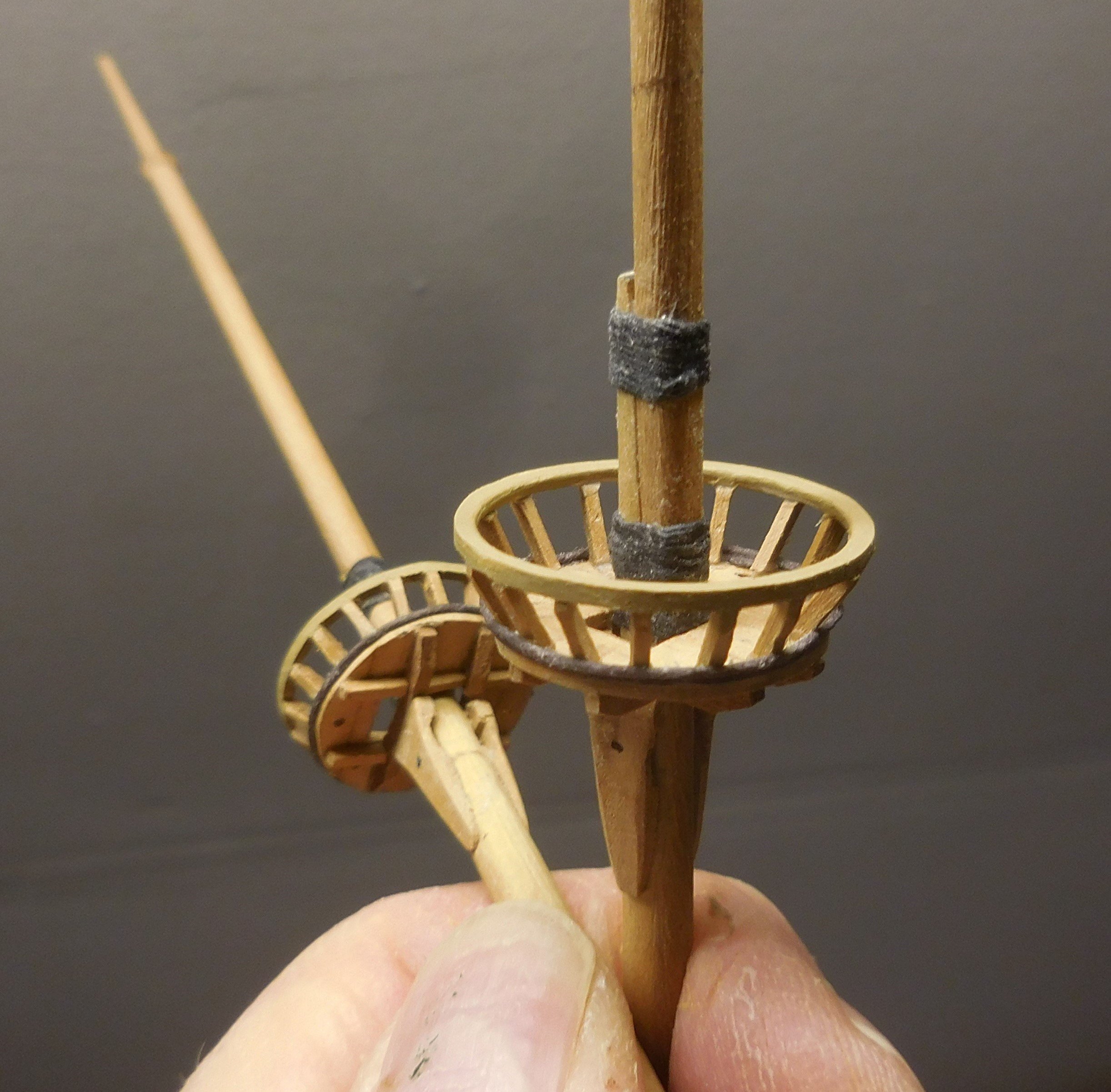
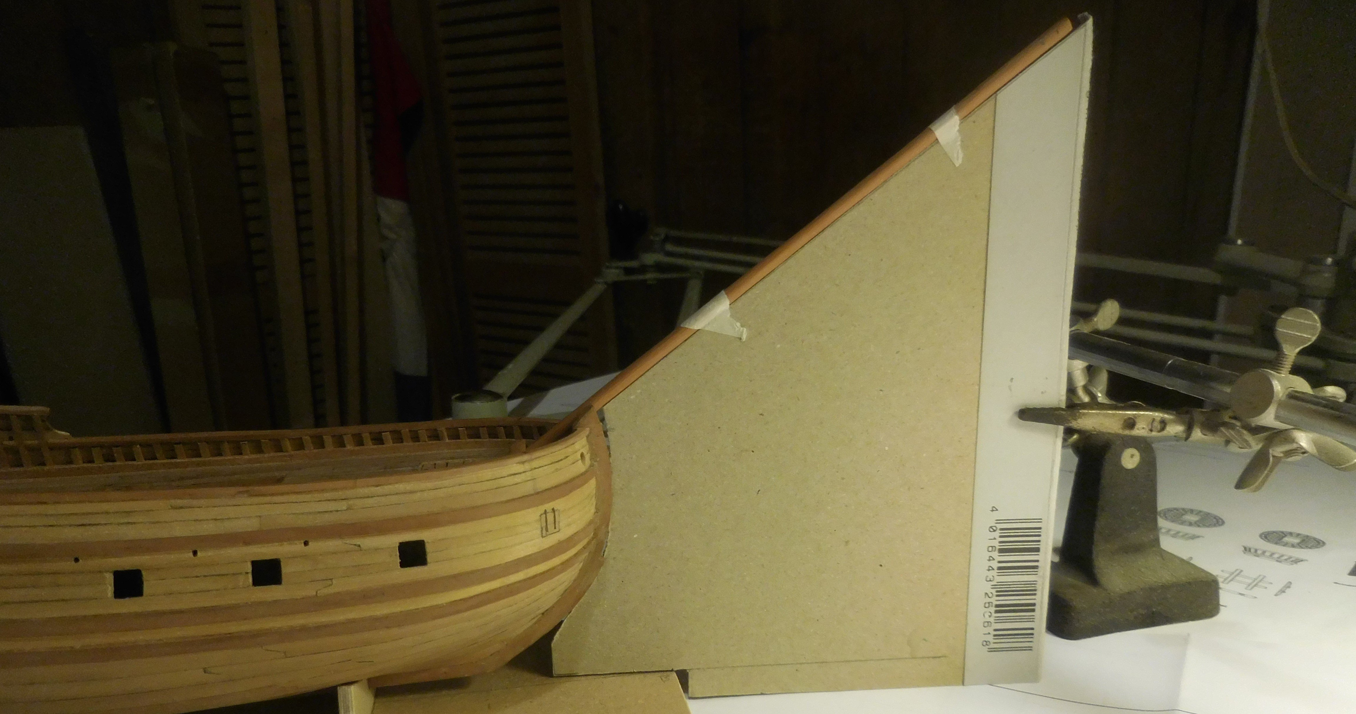
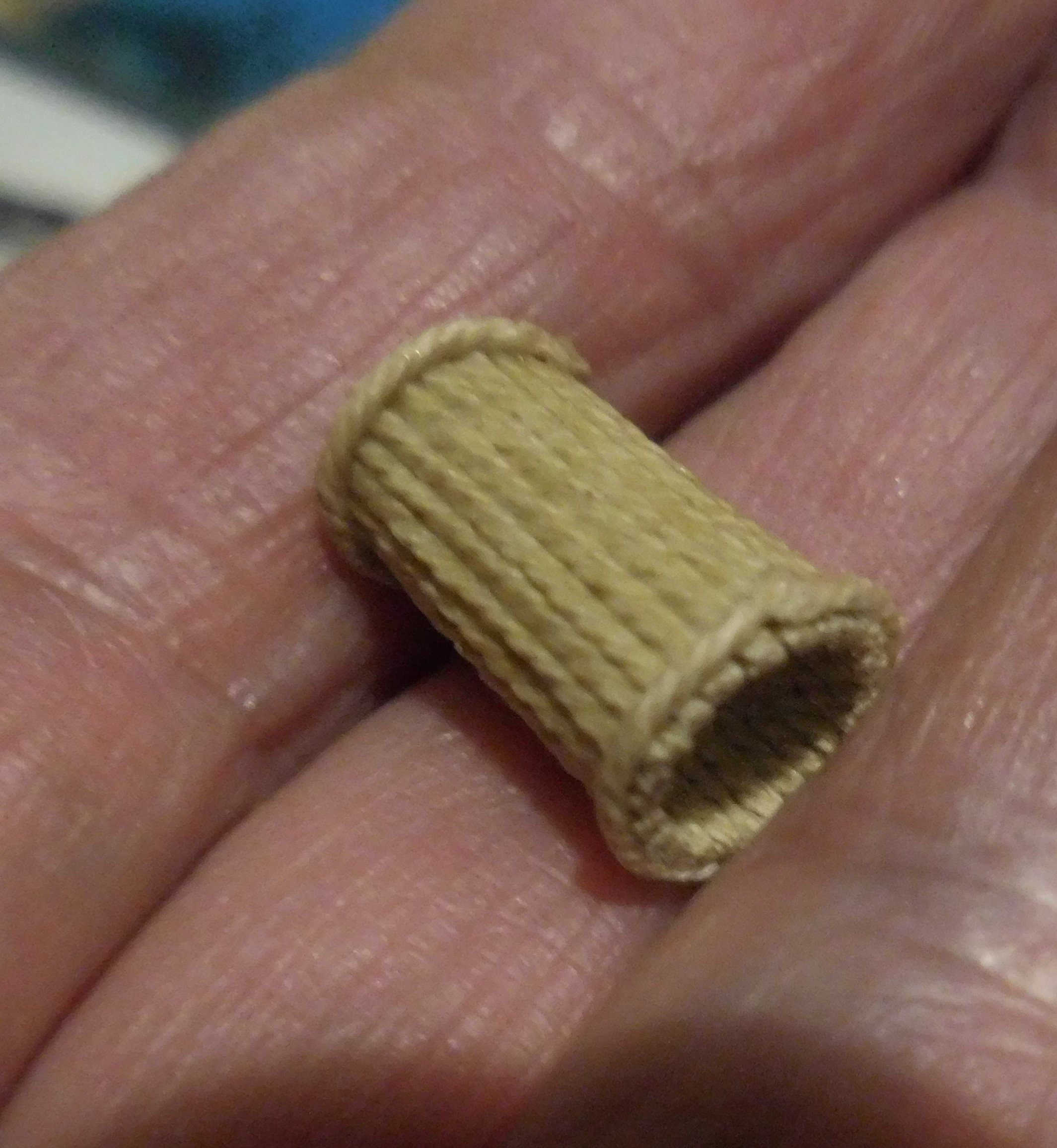
7 Hatches with gratings. The ship has two hatches with gratings, both of which are located amidships, separated by an intermediate beam. B is the blue blade of a large hacksaw, with a slat to protect my fingers. That saw has a thickness of just under 1 mm, which can be used to make a trench of width converted to the scale 1 : 87 is .7,5 cm The holes in a grating should never be larger than 7.5 cm, otherwise the crew will break their ankles when they walk over them. I made a guide through which I slided a bundle of slats (A) of 2.5 x 0.8 mm. Slots were then carefully sawn in them that neatly stop at the thickness of the two metal rings that are under the saw. If a little too much is sawn away on those rings, I could turn those rings in a different position In this way, thin planks with slots are created, which glued together, form a grid. The masts, bowsprit and the yards. Nowadays we know almost everything about the rigging and masts of the ships after 1600. This is only partly the case with ships from before that time, to which this ship also belongs. For that reason, a few things had to be thought of myself, as if I were in the shoes of the skipper at the time. These will be discussed in the course of the story. The foremast and the mainmast are keel-stepped, the mizzenmast stops in the deck above the tiller. The mizzen mast is in fact pulled backwards when the shrouds are attached, because this type from before 1600 did not use a mizzenstay. This mast had to be supported backwards. I solved this by putting a wooden bobbin between the mast and the front of the cabin. The three masts, the yards and the bowsprit are made of pear wood, cut and filed to the right thicknesses and tapered. On 17th century ships, it was customary to make the topmasts extendable, a novelty that was applied at the end of the 16th century. This ship may have had sewn topmasts on the foremast and the mainmast. However, the replica that was built in Harlingen, and was completed in 2023, has extendable topmasts. The connection between the mast and the top mast is not extendable. The angle of the bowsprit in relation to the waterline was accurately transferred to a piece of cardboard, after which the bowsprit was glued into the hole and support provided for this purpose. In the photo above, the lack of the mizzenstay is clearly visible. Apparently, a basket was attached to the top of the mizzenmast, which can be seen in the drawings of Gerrit de Veer. I made the basket by attaching glued rope to a plastic pen, a ballpoint pen. Above and below the basket, the pen was covered with double-sided tape, to keep the ropes in place. After drying, the basket could be cut loose and a bottom, also made of rope, was added. On the drawings of Gerrit de Veer it is not clearly visible whether a gammoning has been applied between the bowsprit and the head knee. In order to relieve the pull on the bowsprit upwards, this seems to be necessary, as later ships in particular show. In any case, I applied it, just like with the replica in Harlingen.

.thumb.JPG.72feebe3af52597d4cd57ddcbaaa938c.JPG)

.thumb.JPG.8d26134da008c59942548bf3f14f7c01.JPG)
-
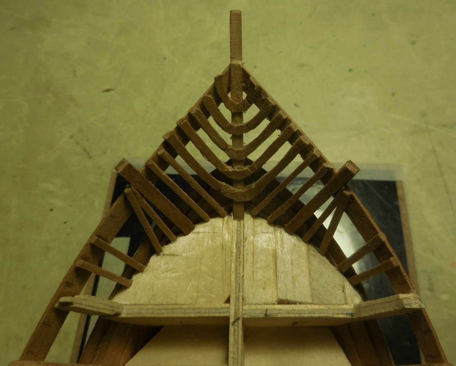
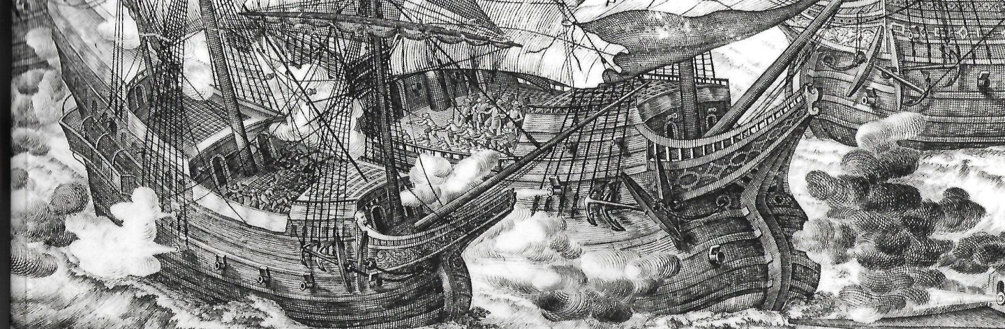
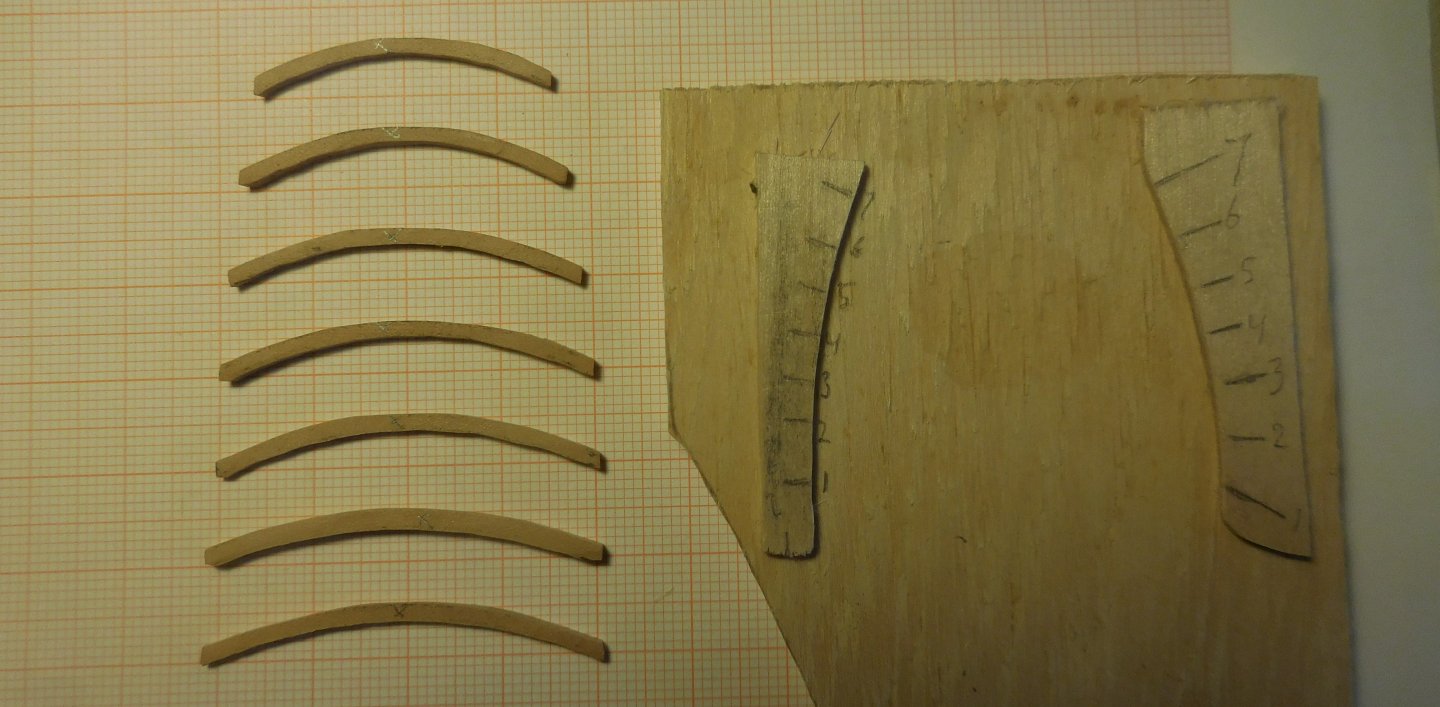
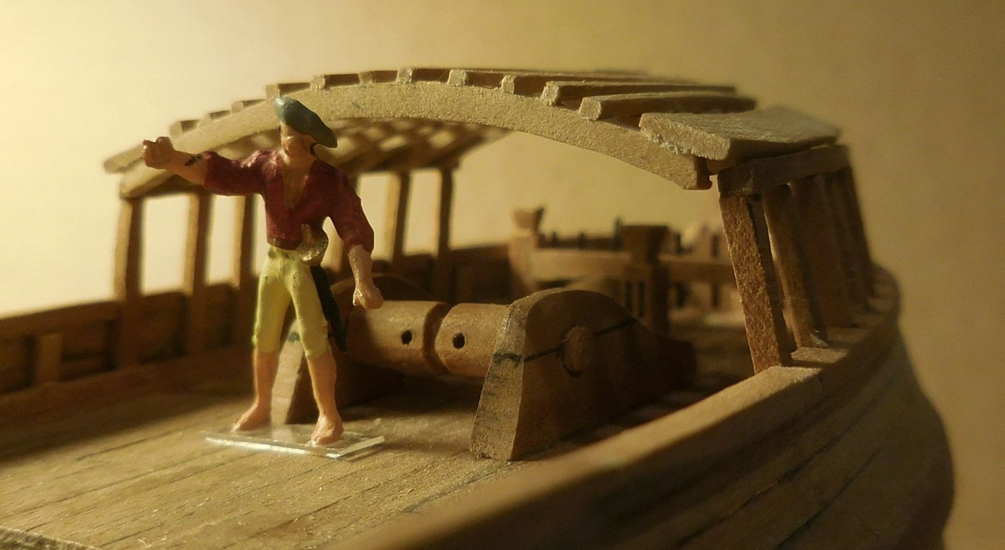
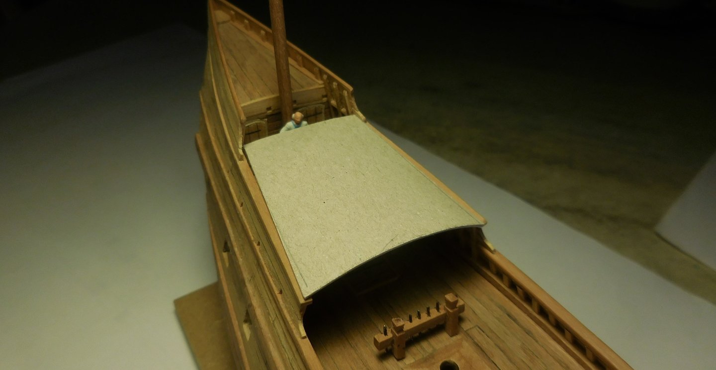
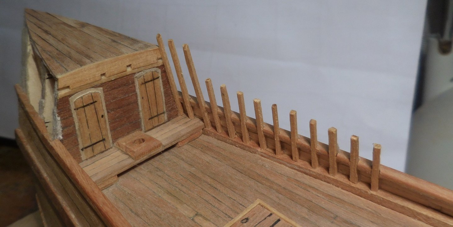
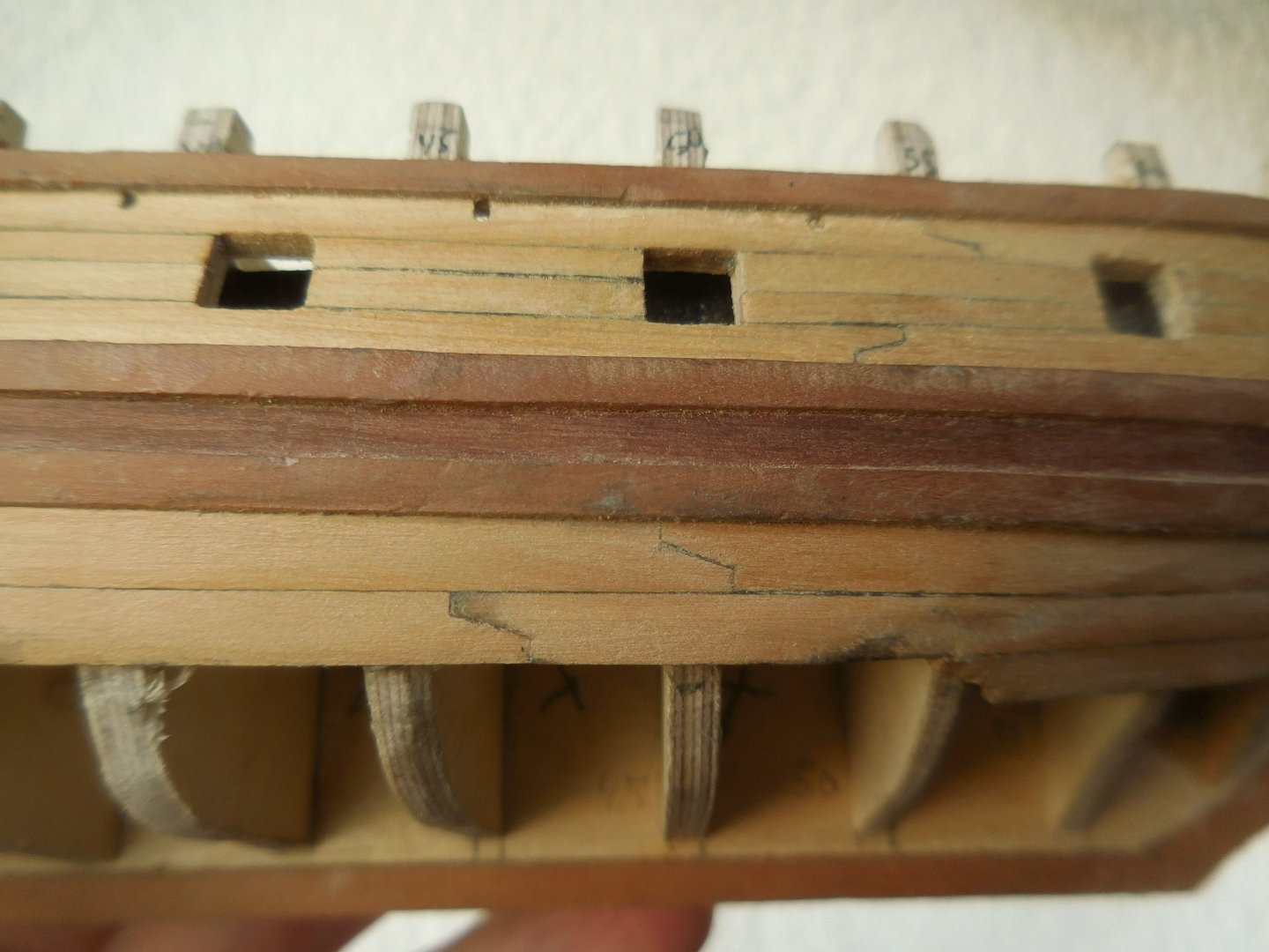
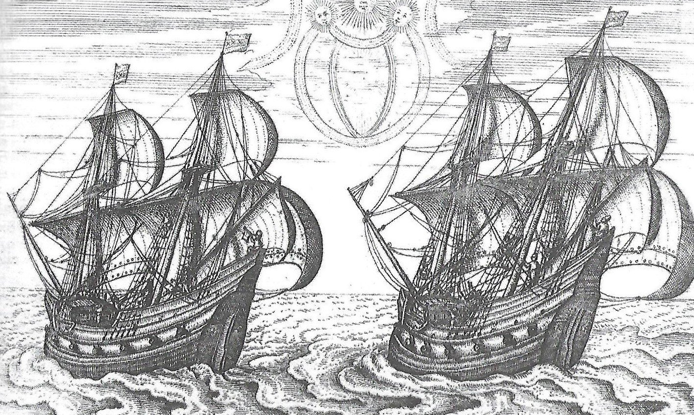
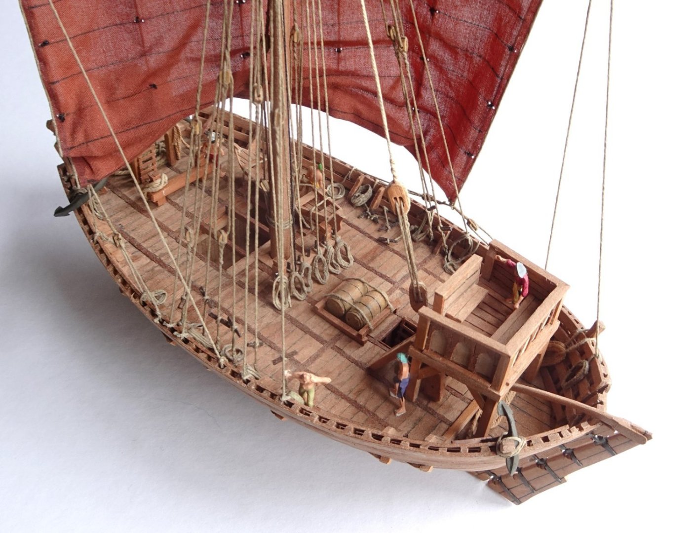
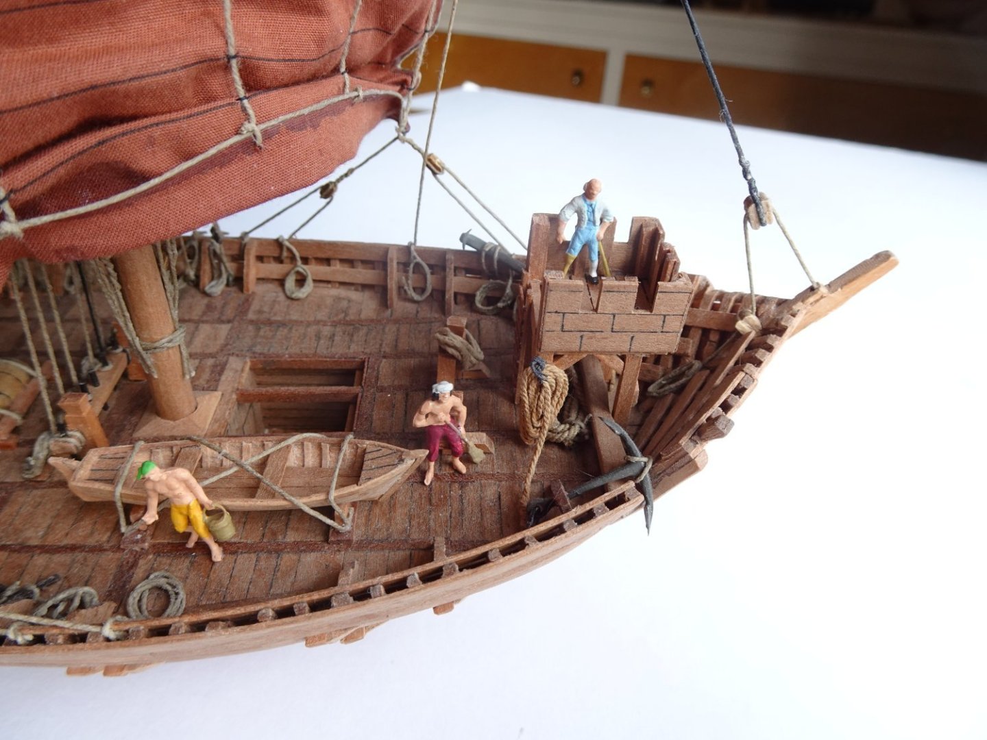
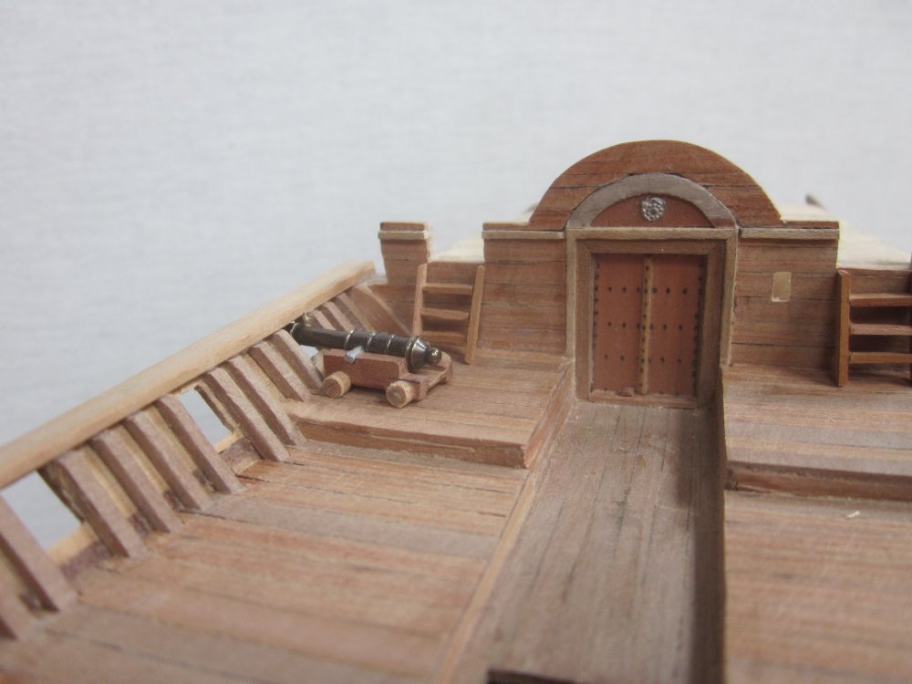
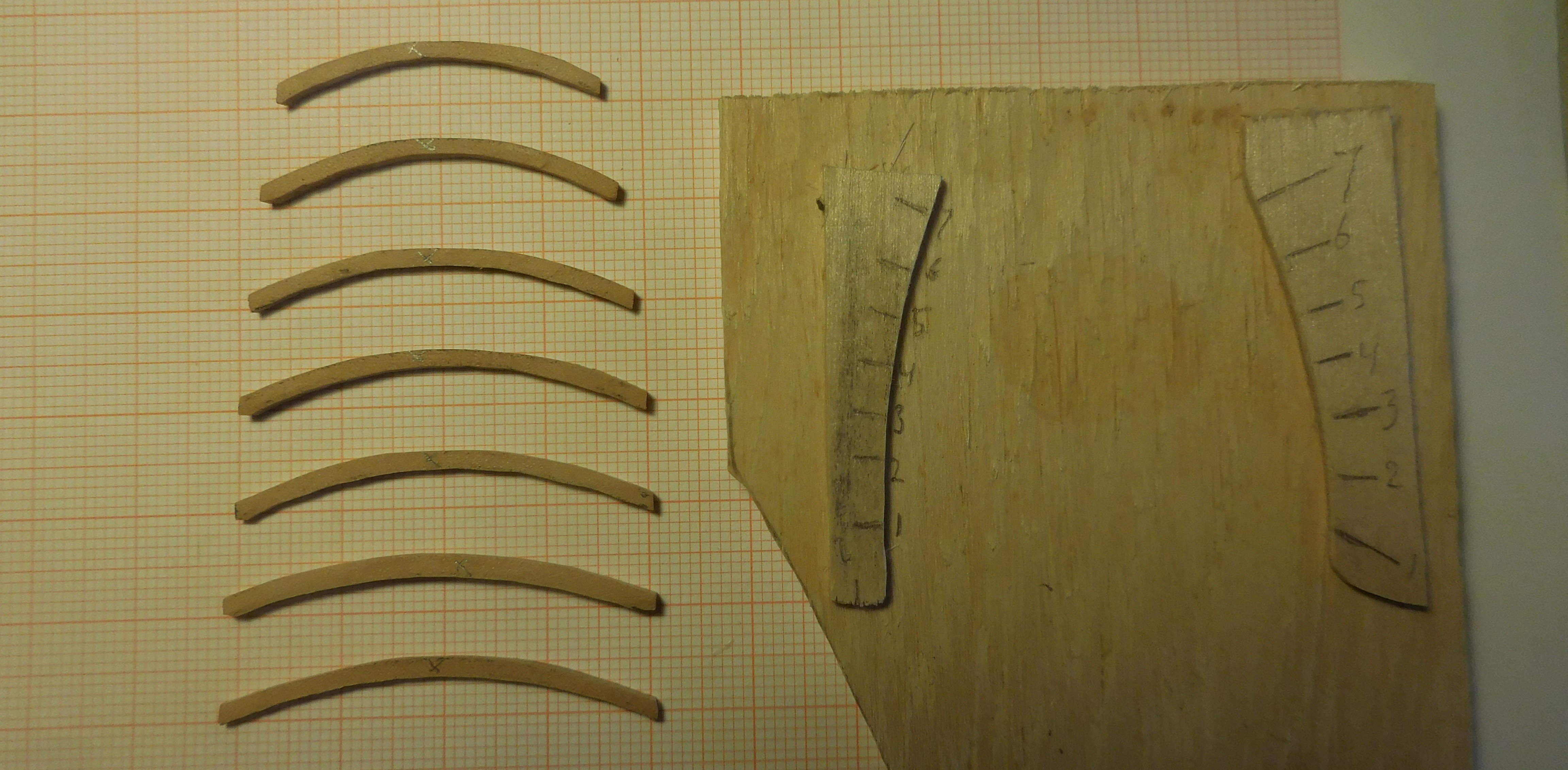
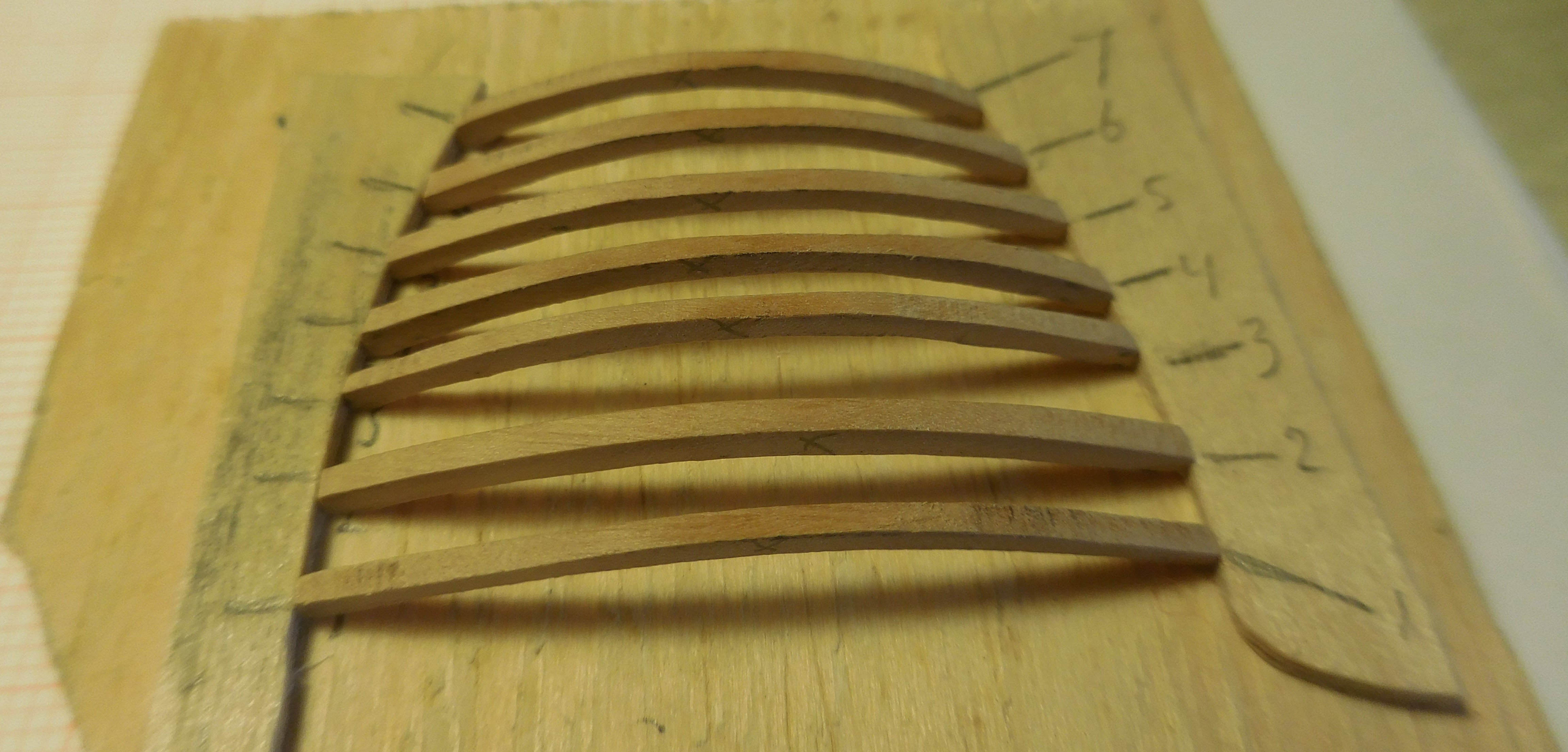
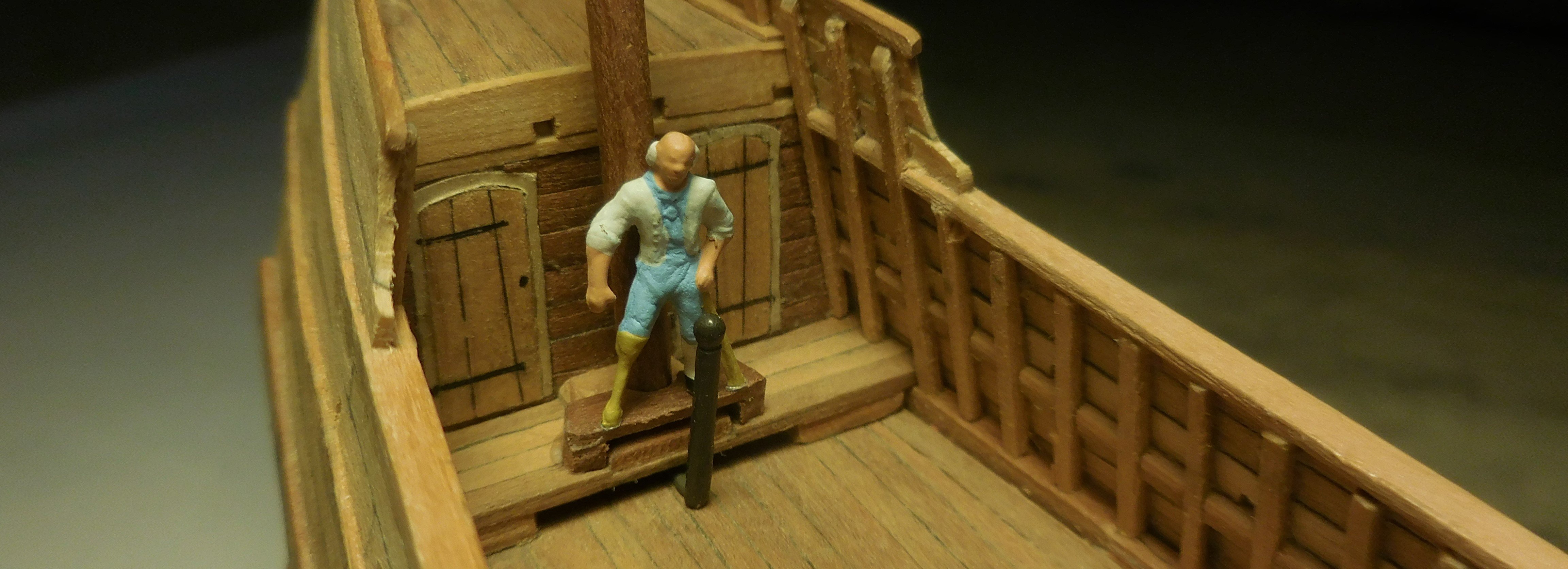
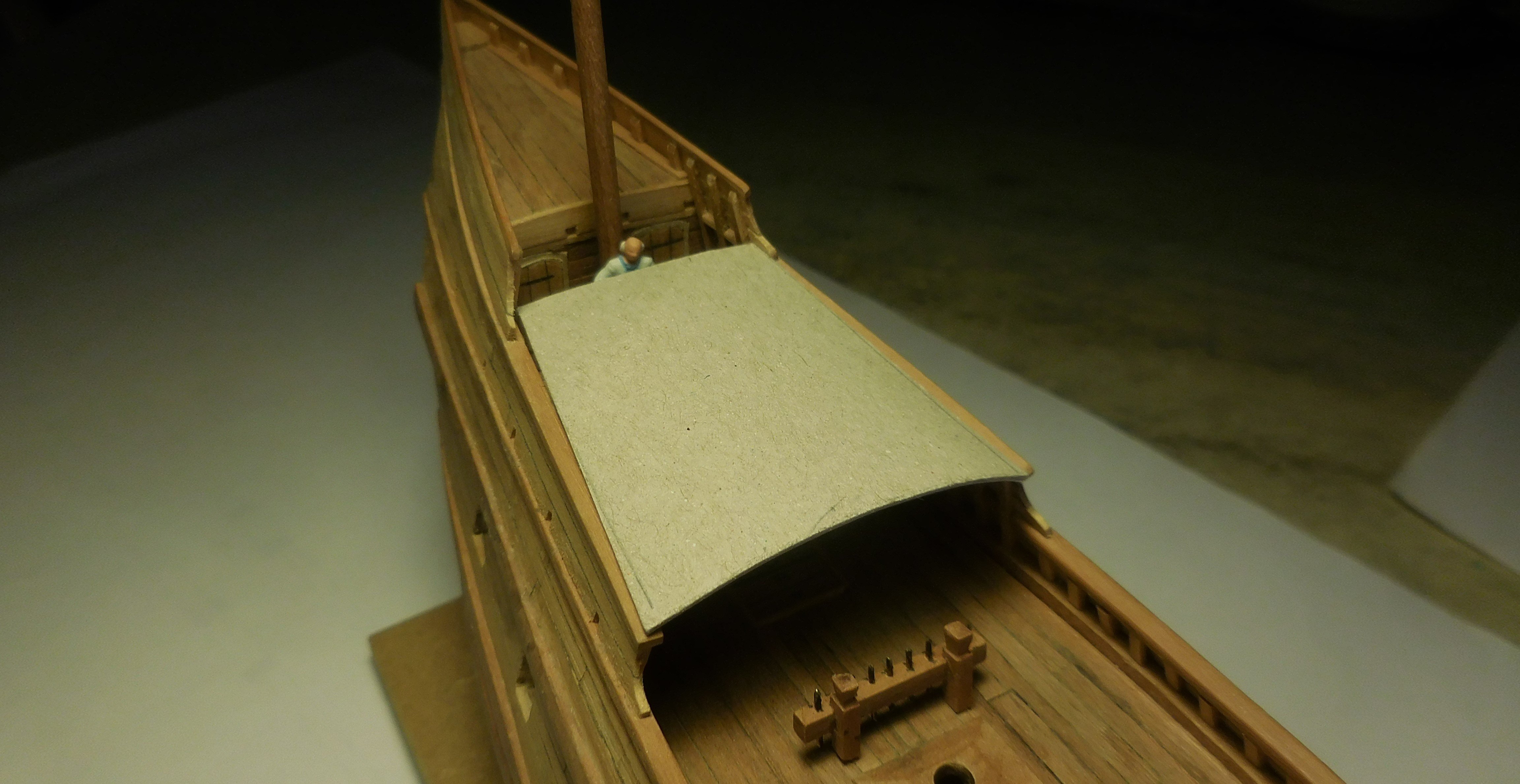
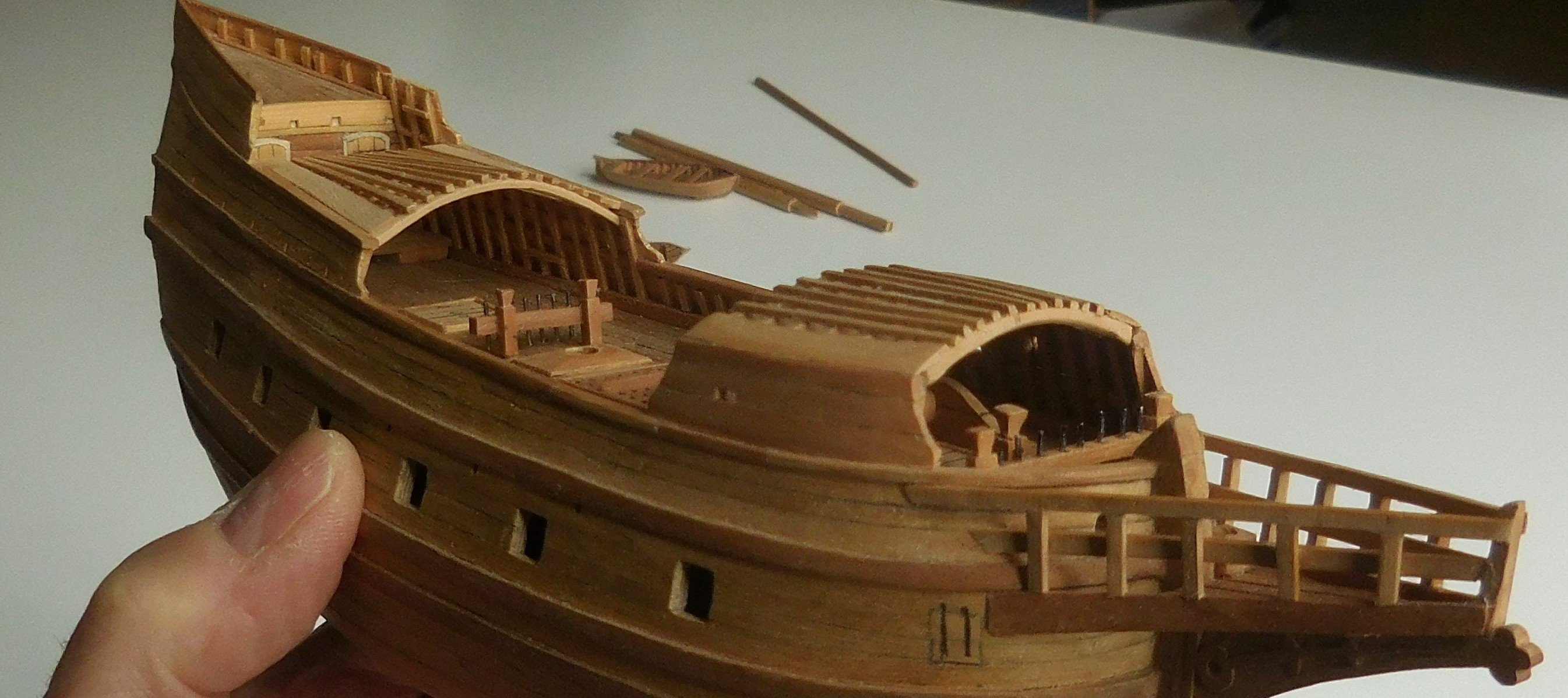
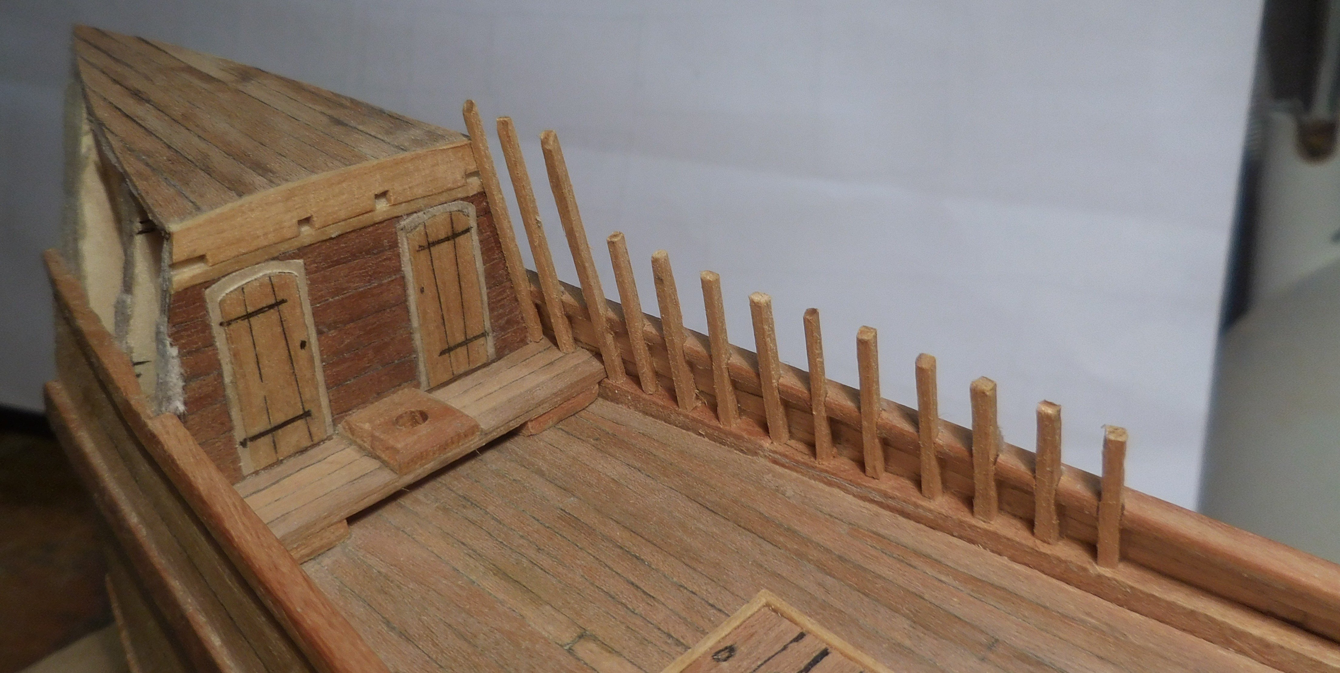
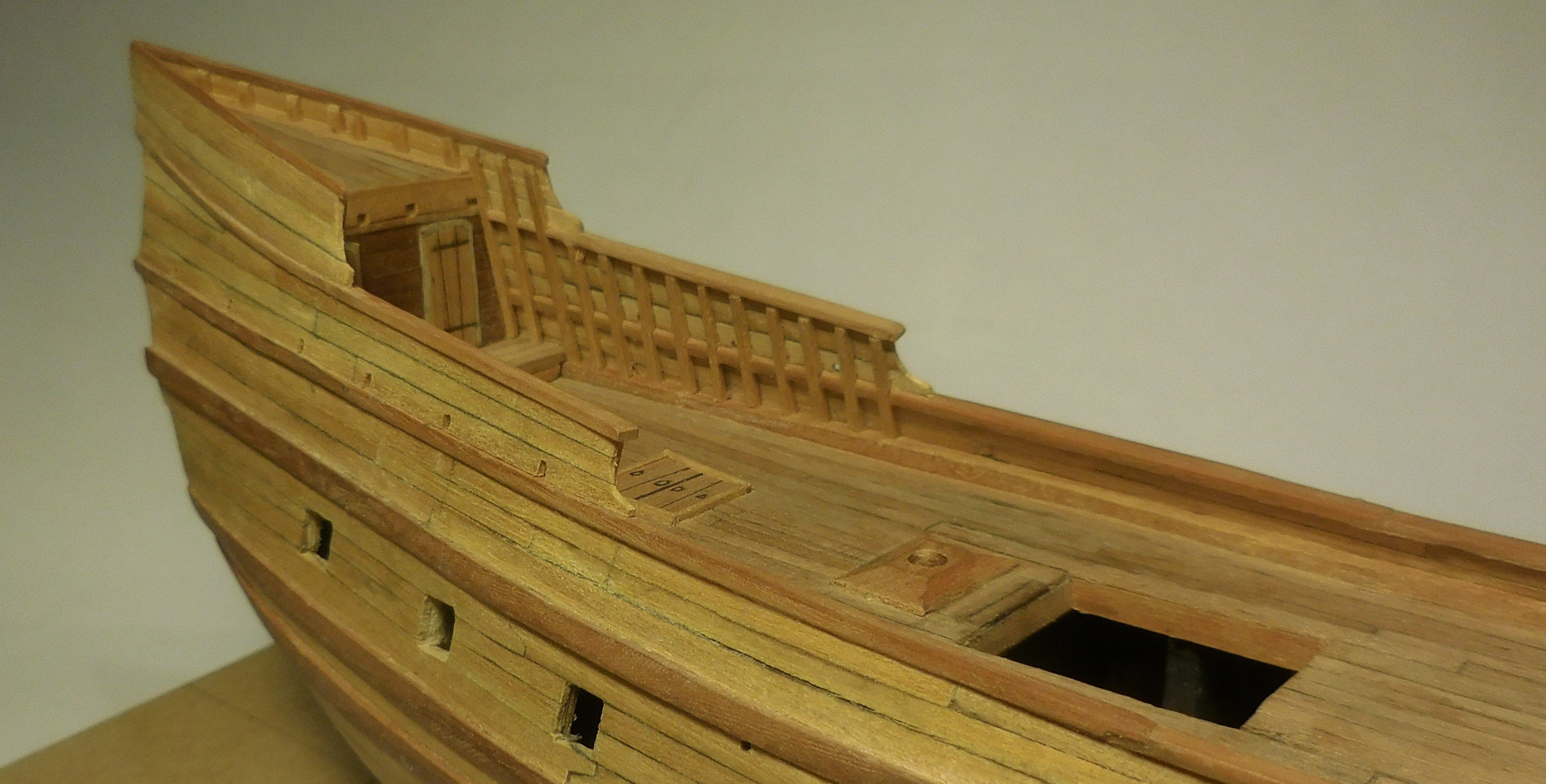
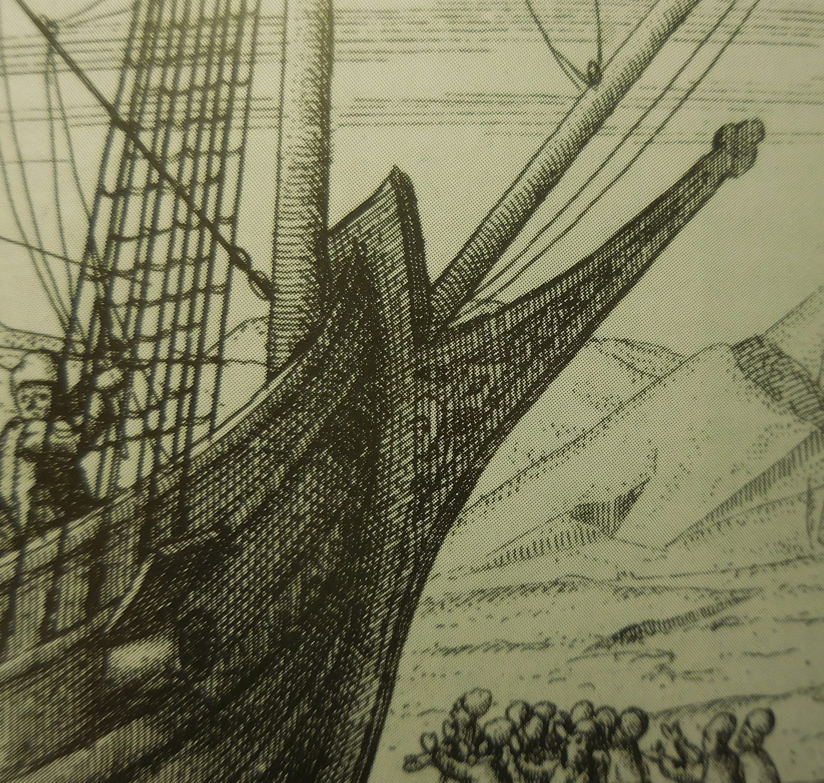
6 On the forcastle, and midships, I built a lattice as can be seen on this old picture of the battle at Bantam in 1601. This lattice was a feature which was common on merchant ships at the time. It had to be a defense system in case the ship would be boarded by pirates. Initially, it was a net of heavy ropes, but later it became a wooden lattice. I only know the Dutch name for this construction "boevennet". If you were to translate it, it would become "crook's net" The holes in the grid were such that they could be used to poke with spikes to target the attacker on the net from below. Much later, this completely disappeared and the lattice became a permanent deck. On each side I attached stanchions which had to support the lattice over the forcastle. The lattice must then be placed on top of this, consisting of a number of curved beams with slats attached transversely. The beams do not have the same width, but they must have the same height. Each beam had to be calculated and drawn separately, and sawn from thin pear wood. On the shelf next to it, the mold is made that corresponds to the tops of the stanchions. To determine how high the lattice should be, a HO figure of a sailor was placed underneath before attaching the construction. It looks like a tall construction, but the headroom underneath is barely 170 cm in the middle. In order to be able to determine the correct shape of the lattice midships, a helmsman was placed who had to be able to see just over the lattice It turned out that the construction became almost horizontal at the rear and curved at the front. This shape was adopted on the rafters that were placed on the edges midships. A ship of that size usually carried three anchors. I made two of them, of different sizes. They are sawn from a brass plate of 2 mm thick, on which I first glued the paper with the right circumference, and then filed it into the right shape. Both palms are made of very thin brass and cut into that shape. The parts are soldered together. This was simply not possible because of the conduction of the heat. A tool was made with a block of balsawood in which the contours of the bottom of the anchor were filed. By clamping the anchor on top of it and sliding the palms underneath, it became a solid unit that could easily be soldered. After that, sticks were made from two halves of pear wood. Then I painted them in a color: Revell 46 matt. The cannon barrels were also given that colour. Both anchors were placed on the bow. Catheads wer not used at that time. I didn't think it was realistic to equip all gun ports with cannons. Only two of them were fitted with sawn-off cannon barrels. Furthermore, I left two gates open, the others were closed. Channels on which the deadeyes for the shrouds were mounted were not in use in that time. They were attached on a wale. As can be seen on illustrations.


-
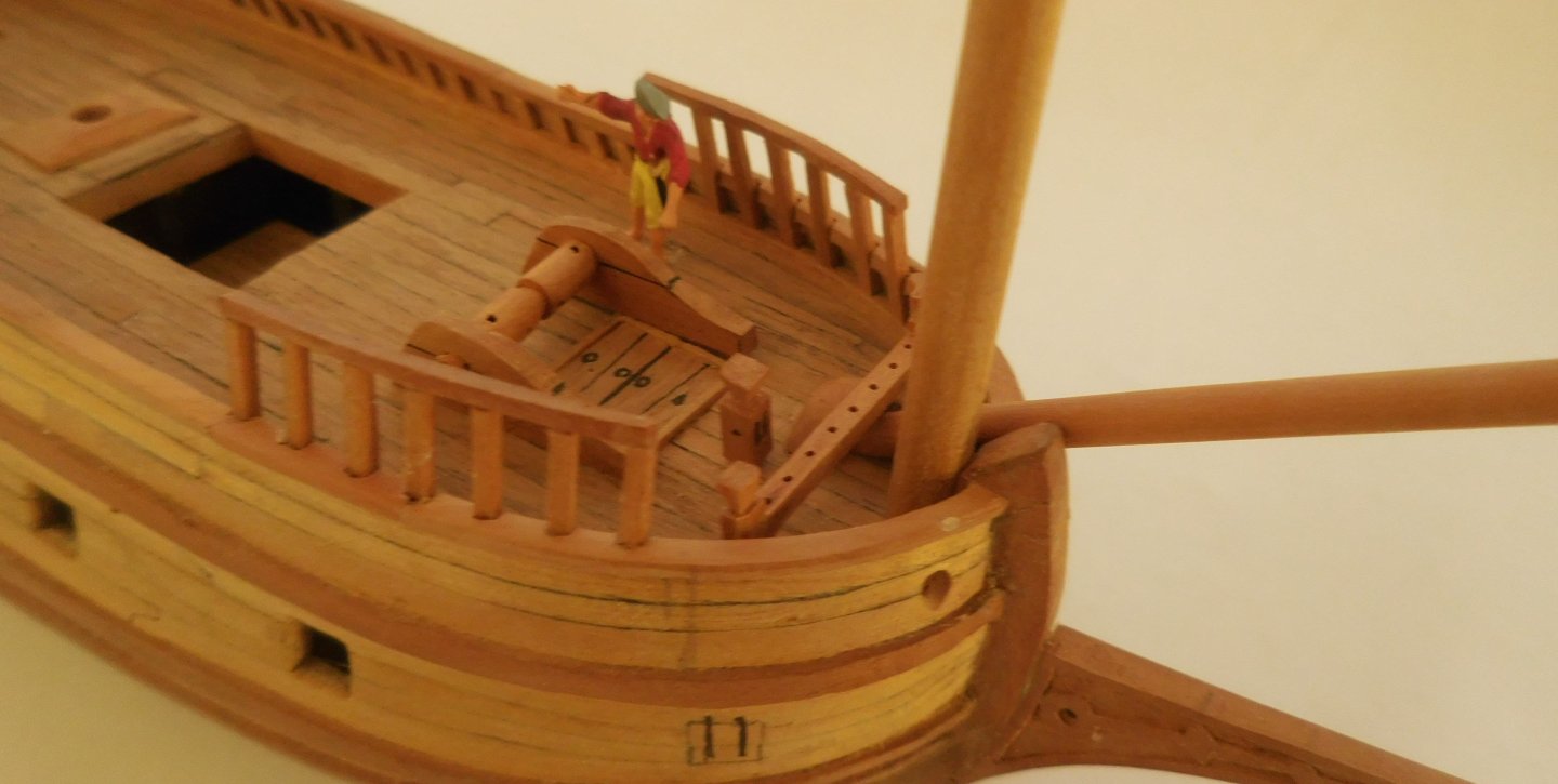
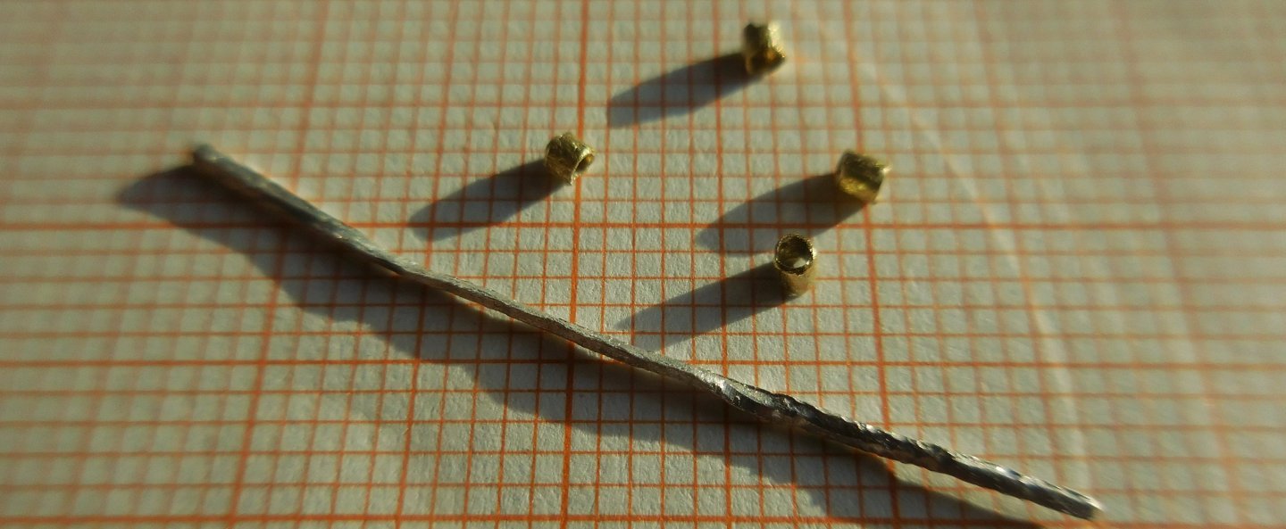
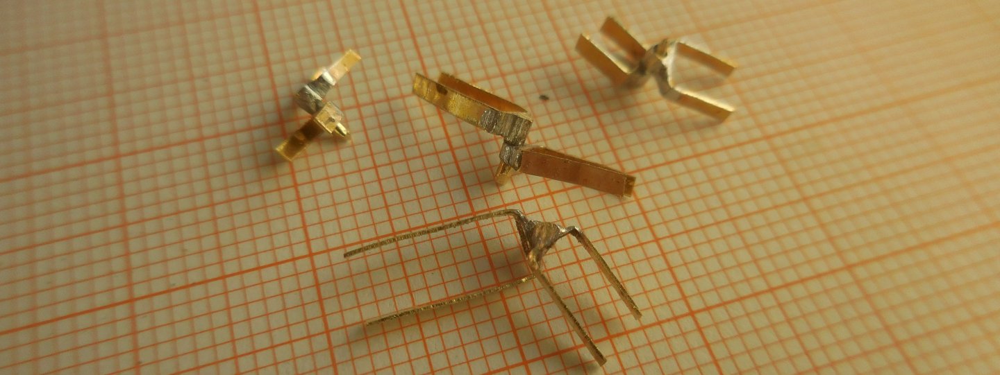
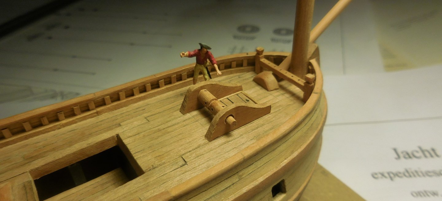
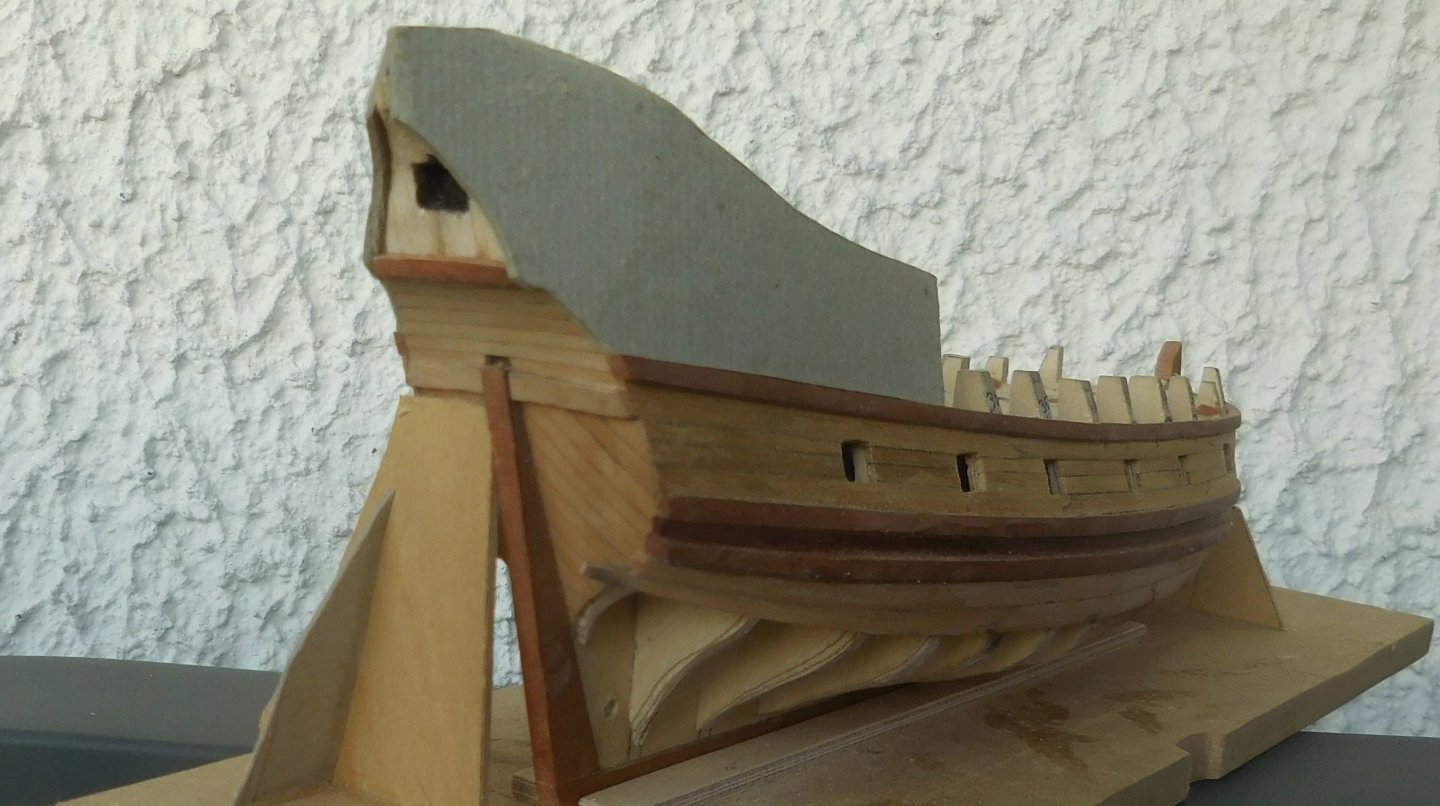
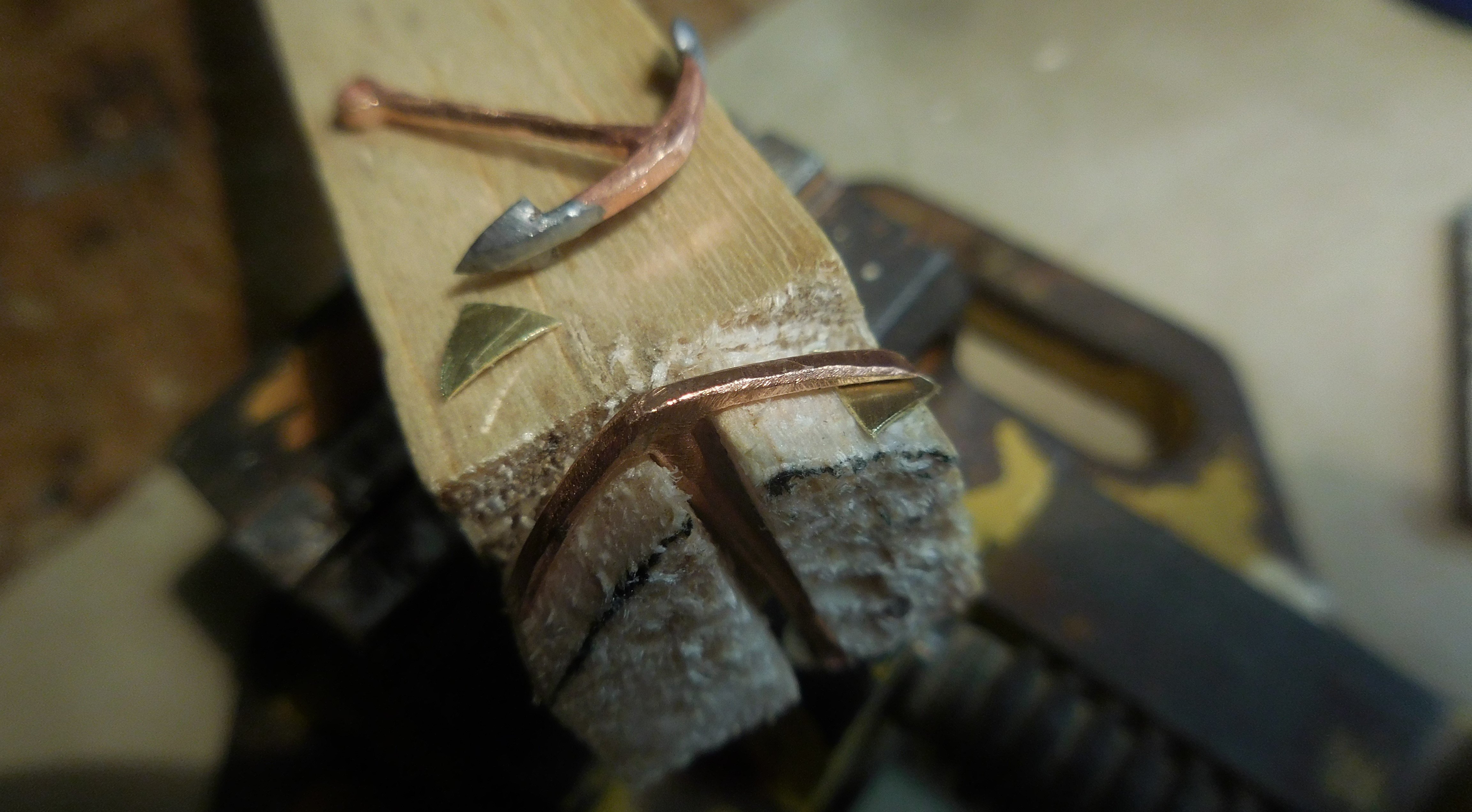
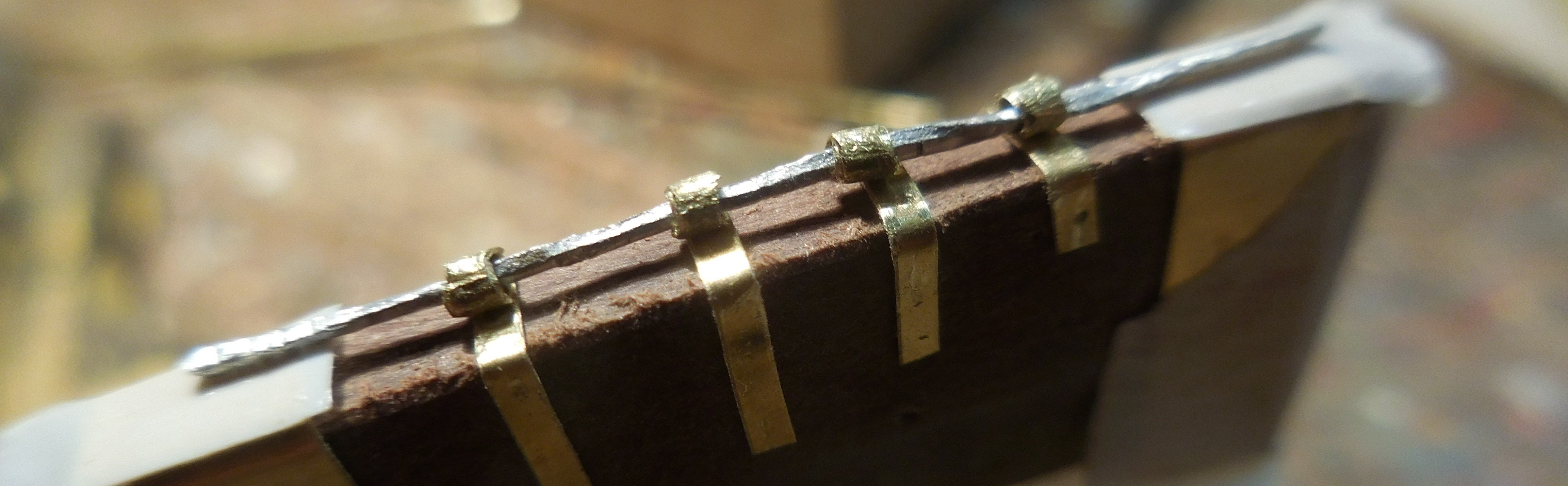
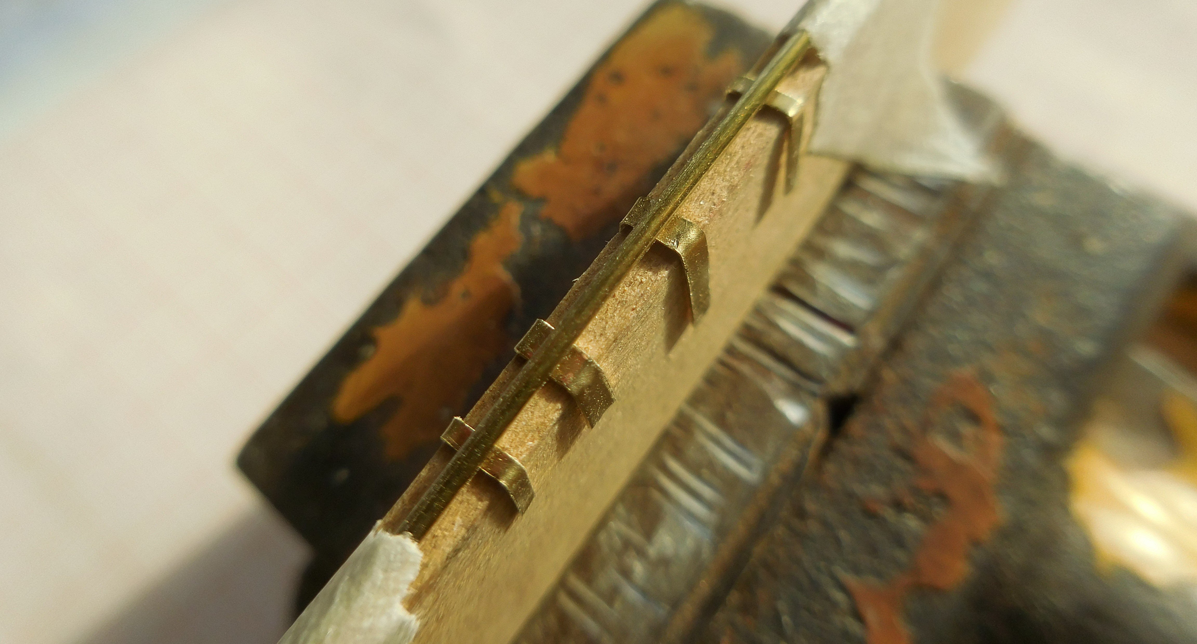
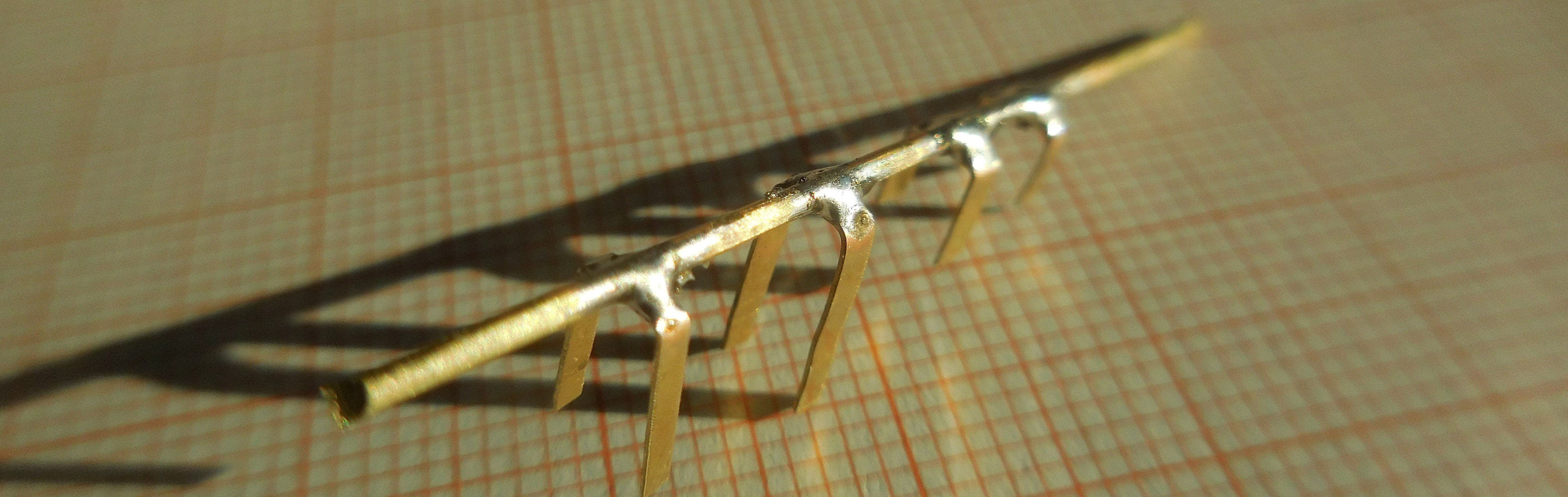
5 The rudder was composed of two planks glued together with graphite in between. I made the hinges from very thin brass plate, copper tube of 1.2 mm thick externally and copper wire of thick.0,8 mm First the making of the tubes, with a length of about 1.2 mm. Then the tails to be attached to the stern. They were bent into the right shape and fixed on a piece of wood of the same thickness as the stern. Through this an aluminum rod of about 1 mm thick. This rod should prevent solder from flowing into the tube. Aluminium cannot be soldered with normal soft solder. All this secured with tape and then soldered. Finally, excess solder was carefully filed away. The pre-bent tails for the rudder were clamped on a piece of wood of the same thickness as the rudder and connected with a copper rod. This was soldered to the tails. After filing away excess solder, the rod between the tails was cut loose and the individual parts were brought to the correct length. This created the hinges ready to be attached to the rudder and stern I never paint the iron parts (including the cannon barrels) black on my models. You don't see this anywhere on old images, always a kind of dark grey, REVELL matt 46. Because it is far from certain what the workplace at the bow looked like, I had to rely on the rather different opinions of Hoving and de Weerdt. As I mentioned before, the windlass could also be used to secure the anchor cable. The anchor bitt has therefore become superfluous and can therefore be omitted. That gives a lot more space at the bow. That extra space seems necessary to me because there had to be room on the deck of Barents' expedition ship to accommodate two boats. The boats could not be towed because they had to sail constantly between large ice floes. Moreover, Gerrit de Veer writes twice in his book that the boats had to be put out. But there is always the possibility that both boats were stacked on top of each other. Hoving omits the anchor bitt and puts the windlass close to the foremast. De Weerdt does place the anchor beting together with the windlass. As a result, there is not enough space for the two boats. Because I make a model of a pinas, and not the specific ship of Barents, my model can suffice with one boat. The situation on the photo above is entirely my responsibility. Directly behind the foremast are dubble bitts with a cross-piece, with holes for a number of belaying-pins for attaching the various ropes that come from above and the front. In addition, there is a bittt, necessary for hoisting the yards in the foremast and the windlass.


-
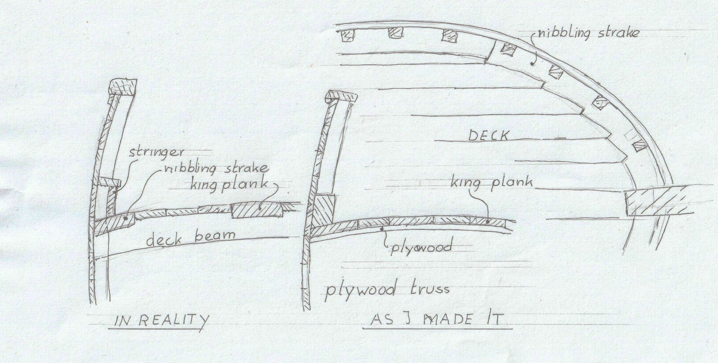
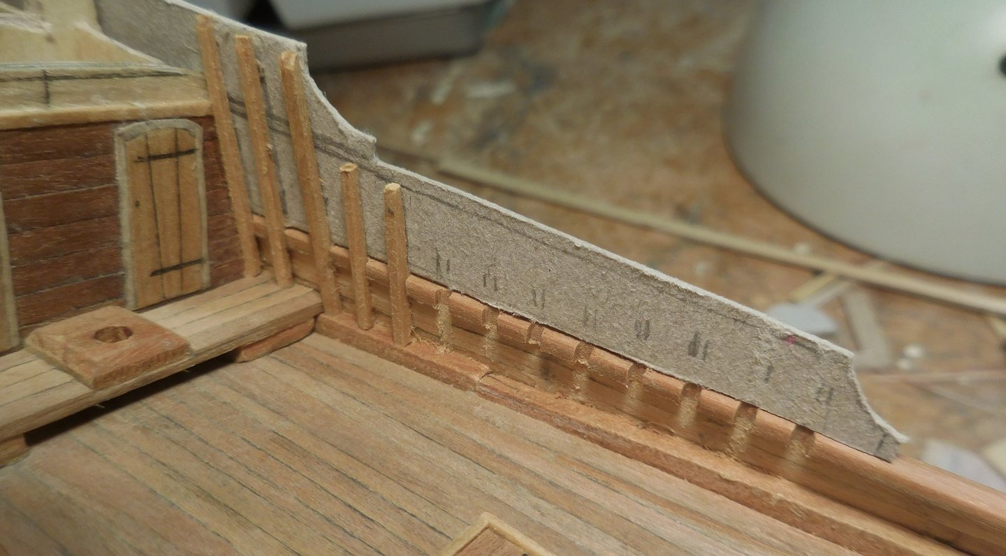
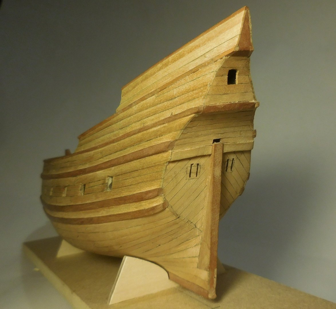
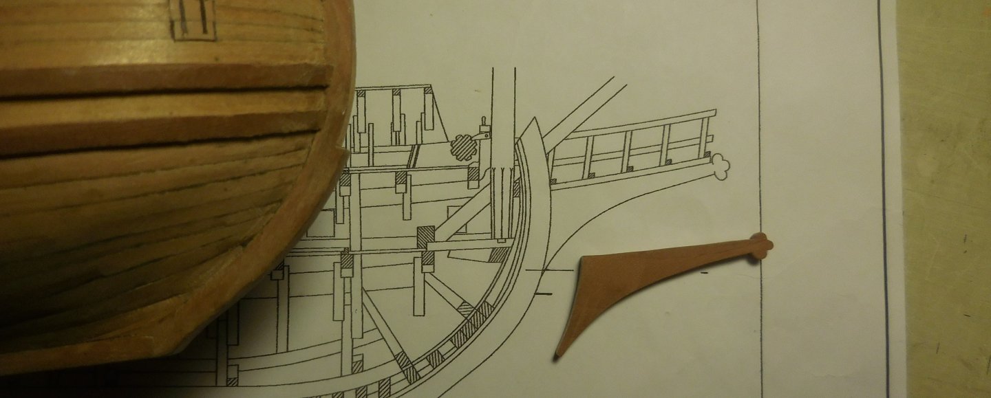
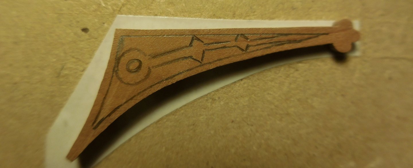
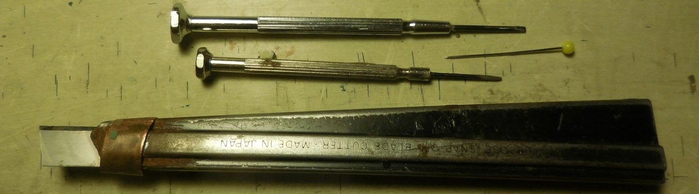
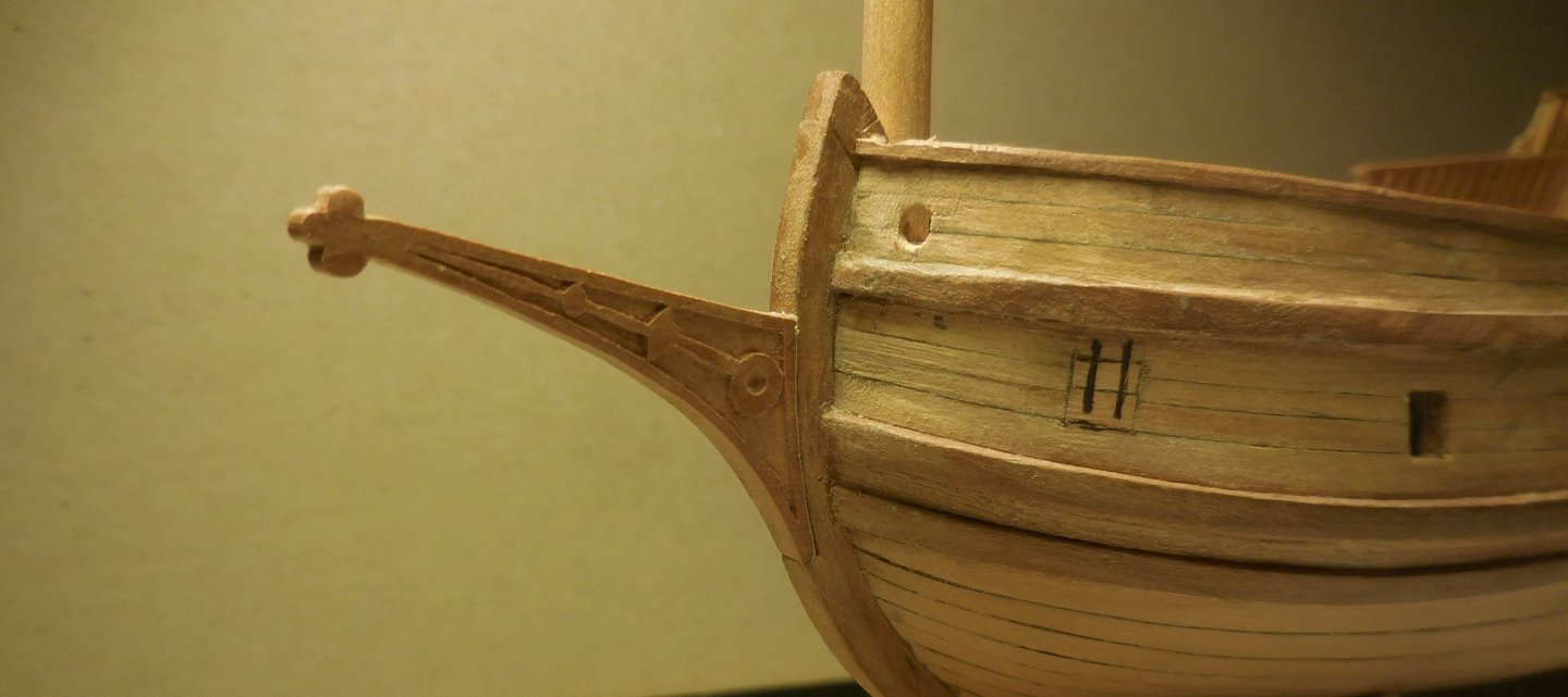
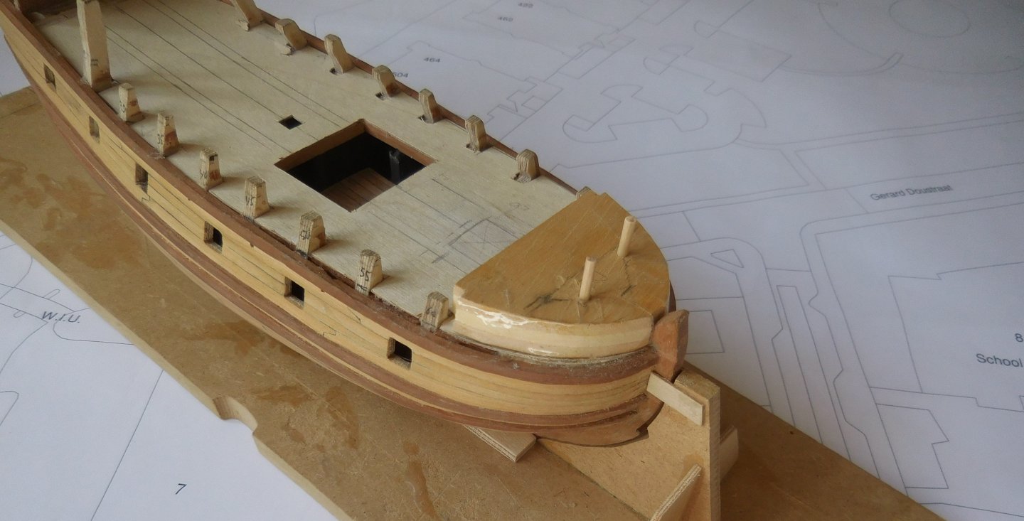
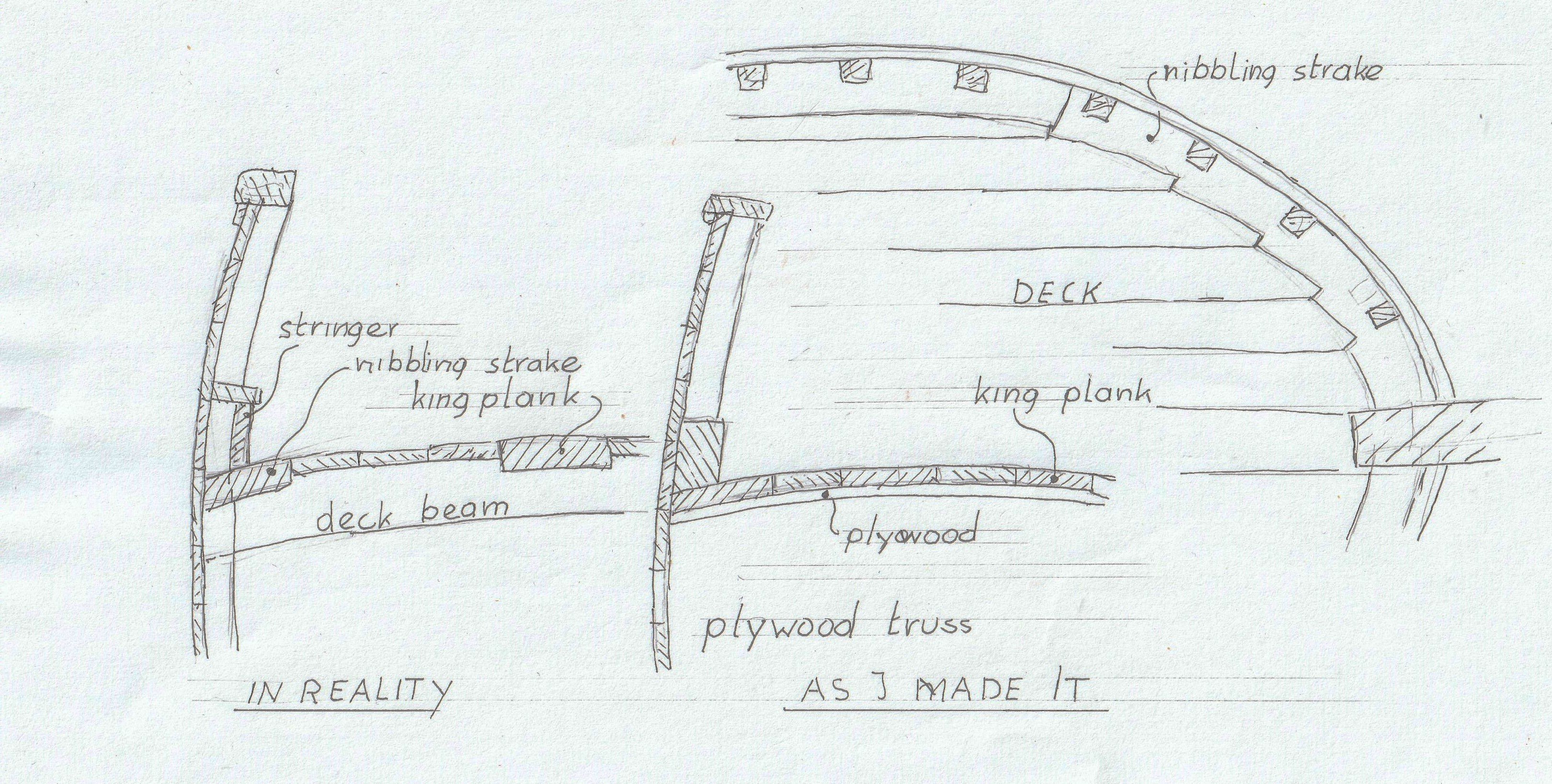
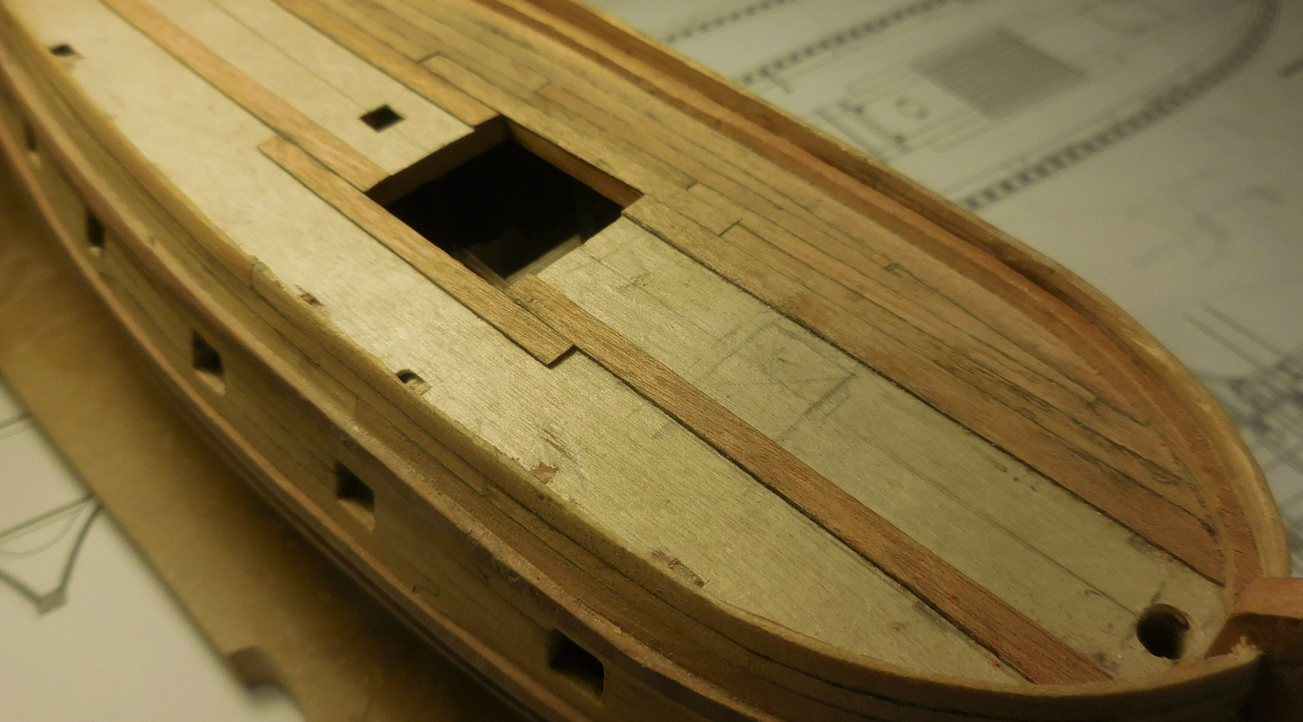
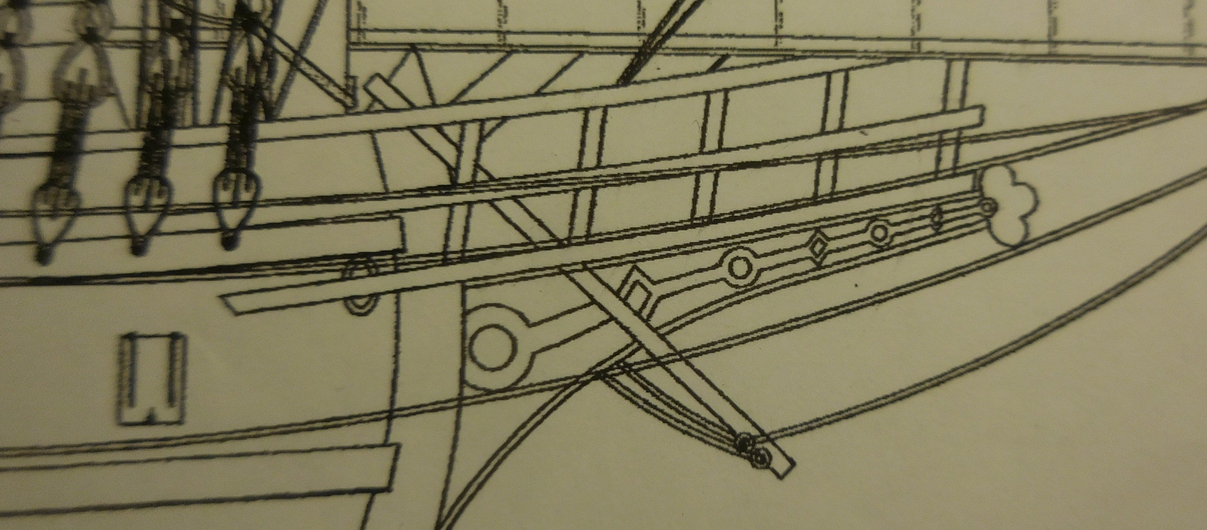
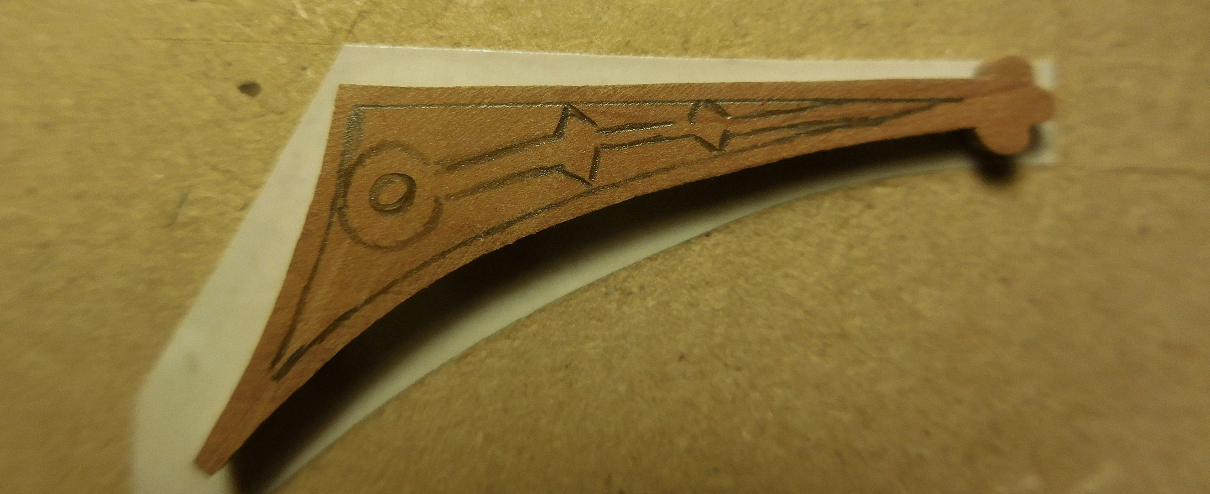
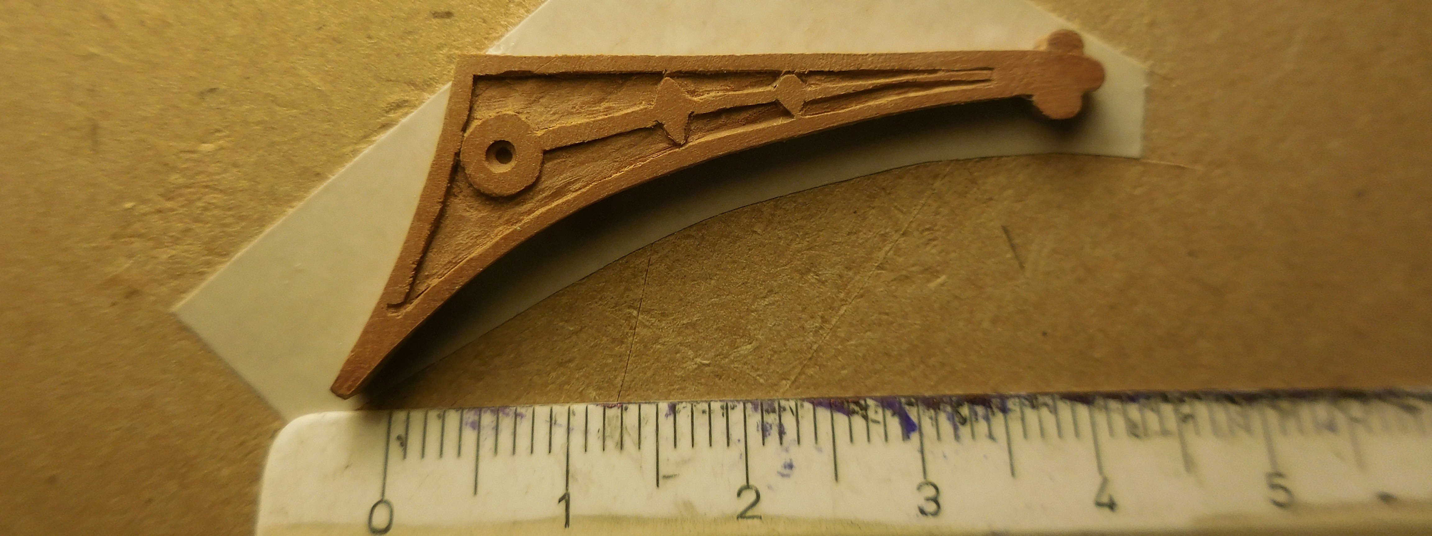
4 In order to meet reality as much as possible, it was necessary to make an elevation along the bulwark. In reality, a stringer ran along the struts, covered with a plank. I made that as a beam along the bulwark with the struts placed on top later. Underneath it ran the nibbling strake. At the top right you can see how I thought the deck planks were notched in a plank along the struts. Hovink thought that was exaggerated and stated that everything had to be done cheaply and quickly with those small ships, and advised to leave that out. On the deck the six king planks, with the planks in between. The planks don't bend with the shape of the hull, but I made different widths that sometimes interlock. On excavated wrecks you never see nice neat straight planks like we do today. It was not important when a plank tapered as also can be seen everywhere in floors of old buildings in those days, and then often very wide. The tree from which they sawed the planks had not the same thickness everywhere. The deck finished. There are three entrances to the deck below. In the middle the large hatch which will be equipped with gratings. In front of the entrances to the cabin is an elevation with a slot underneath. Through that slot protruded the tiller in which at the end was a vertical stick operated by the helmsman, who stood on the elevation in front of the mizzen mast Behind it the hole for the mizzen mast. So the base of the mast was on that elevation. It is not the well-known construction with a whipstaff. There is reason to believe that this was the case here, according to Hoving's research. After applying the rahout, this phase was finished and the two superstructures above the rahout could be started, as supports for a large bend wooden lattice. To keep checking the correct shape of the construction of the after castle and midship, I glued a cardboard mold to the first stanchions with a few dots of glue. On it I drew the shape. Since the stanchions above the deck end up above the rahout, slots had to be made through them. The deck on the cabin is also equipped with planks. The mould has been removed here and the stanchions are ready to be planked on the outside. The drawings in Gerrit de Veer's report show that geometric figures were drawn on the head knee, which was common on such ships of that time. Since I'm not going to paint the model, I had to do it in a different way, and I chose a cut relief. First I copied the contours of the drawing, and sawed out the part. Then I attached it to a board with double-sided tape. The object is so small that it is impossible to edit it without it being fixed on something. First the drawing was applied in pencil, guided by the images of Gerrit de Veer and the interpretation of Ab Hoving. The pattern wasn't quite the same because otherwise it would be way too small. With the following tools I cut it out. Two razor-sharp screwdrivers, a pin and a snap-off knife. The head knee was then attached to the stem.


-
Patric, I like your fine detailed work and I am looking forward to the continuation of this fantastic project! Succes Constant
-
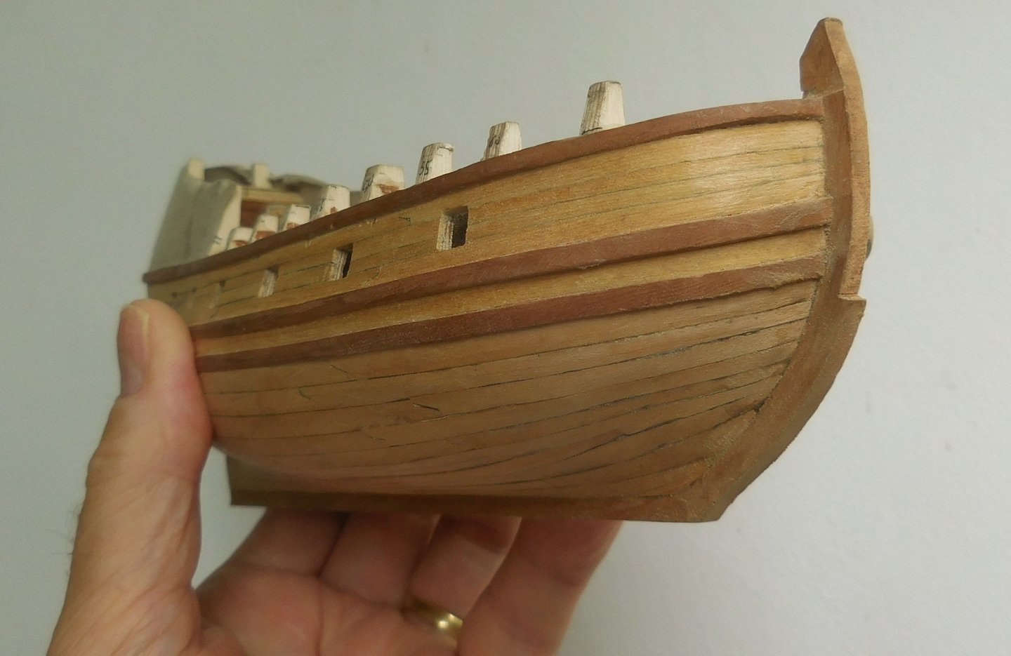
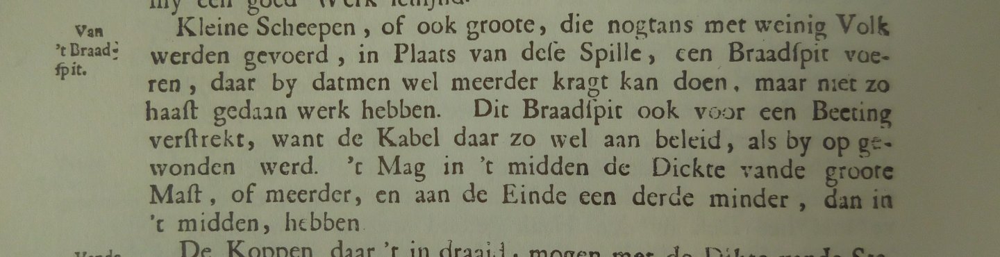
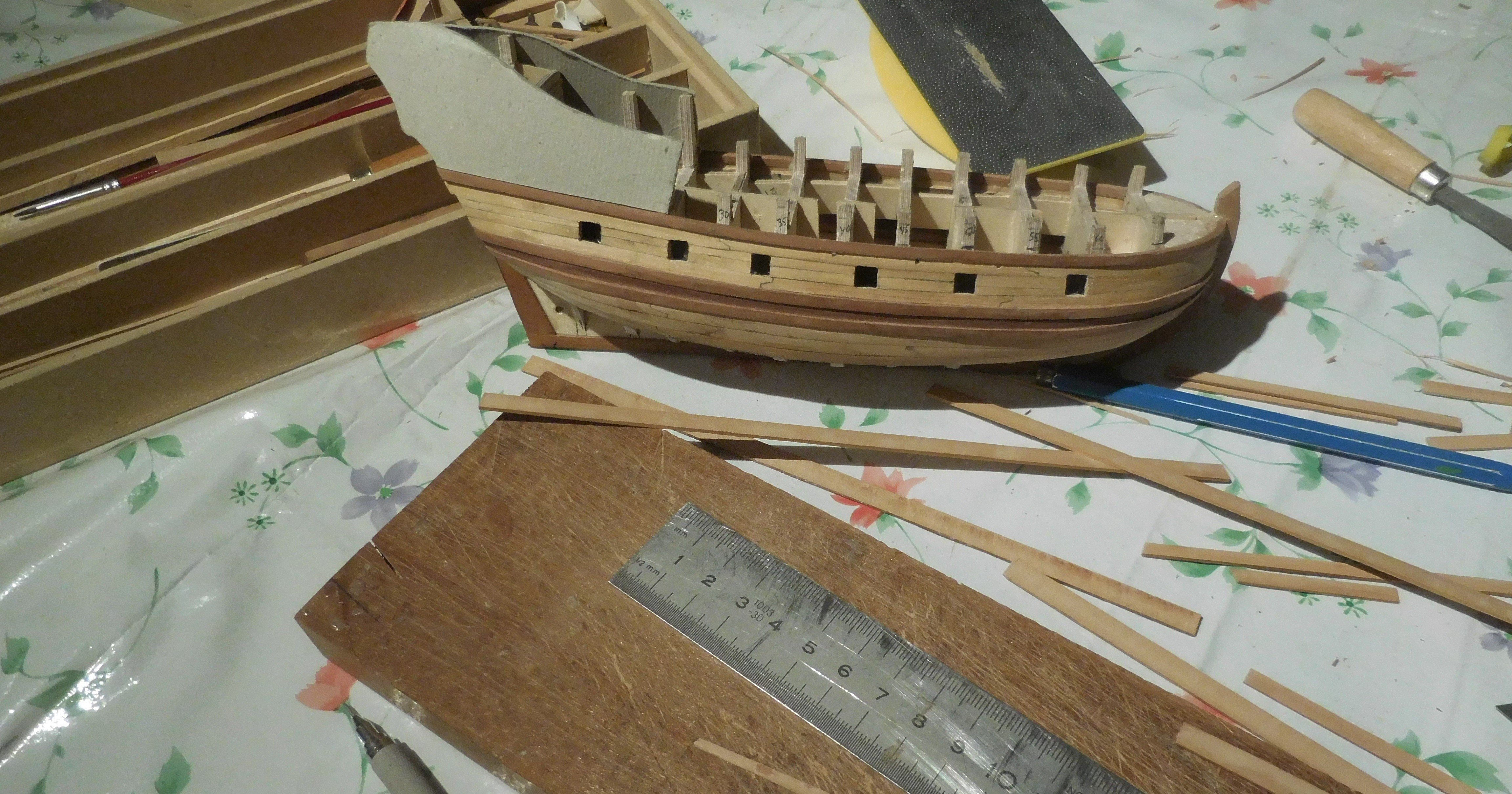
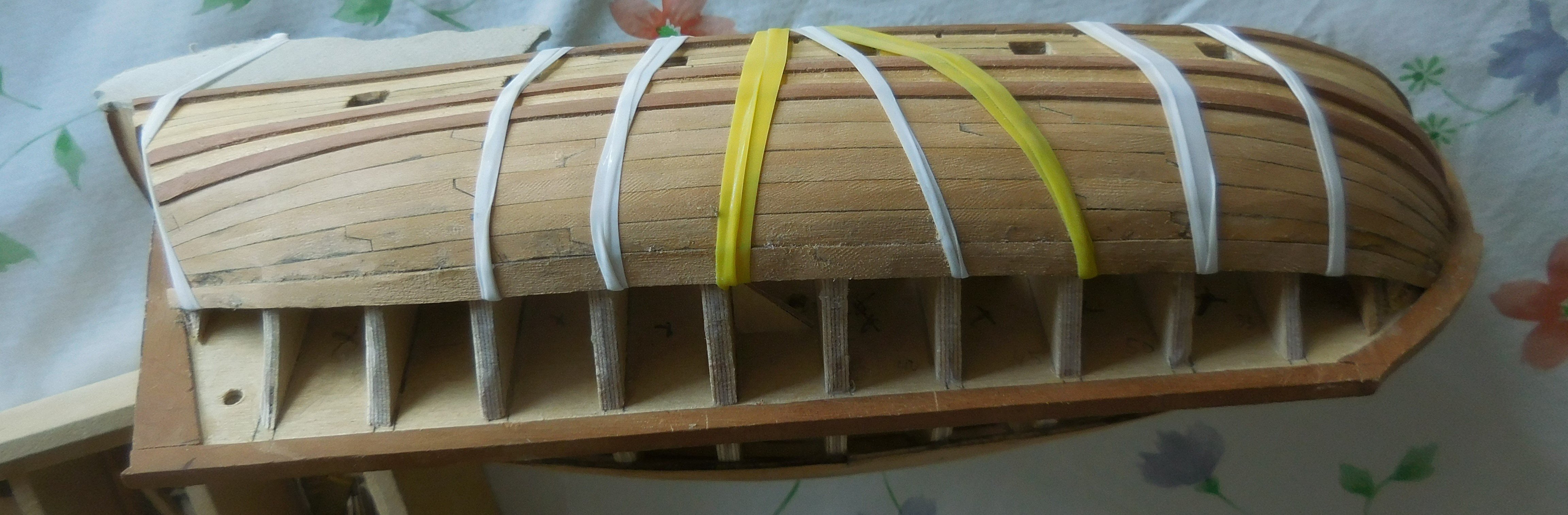
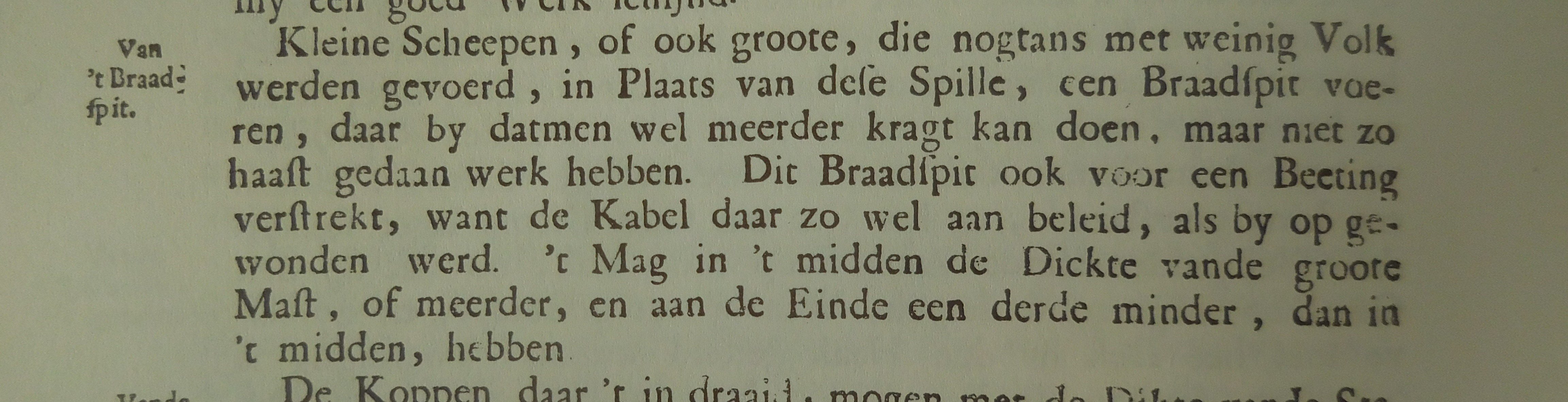
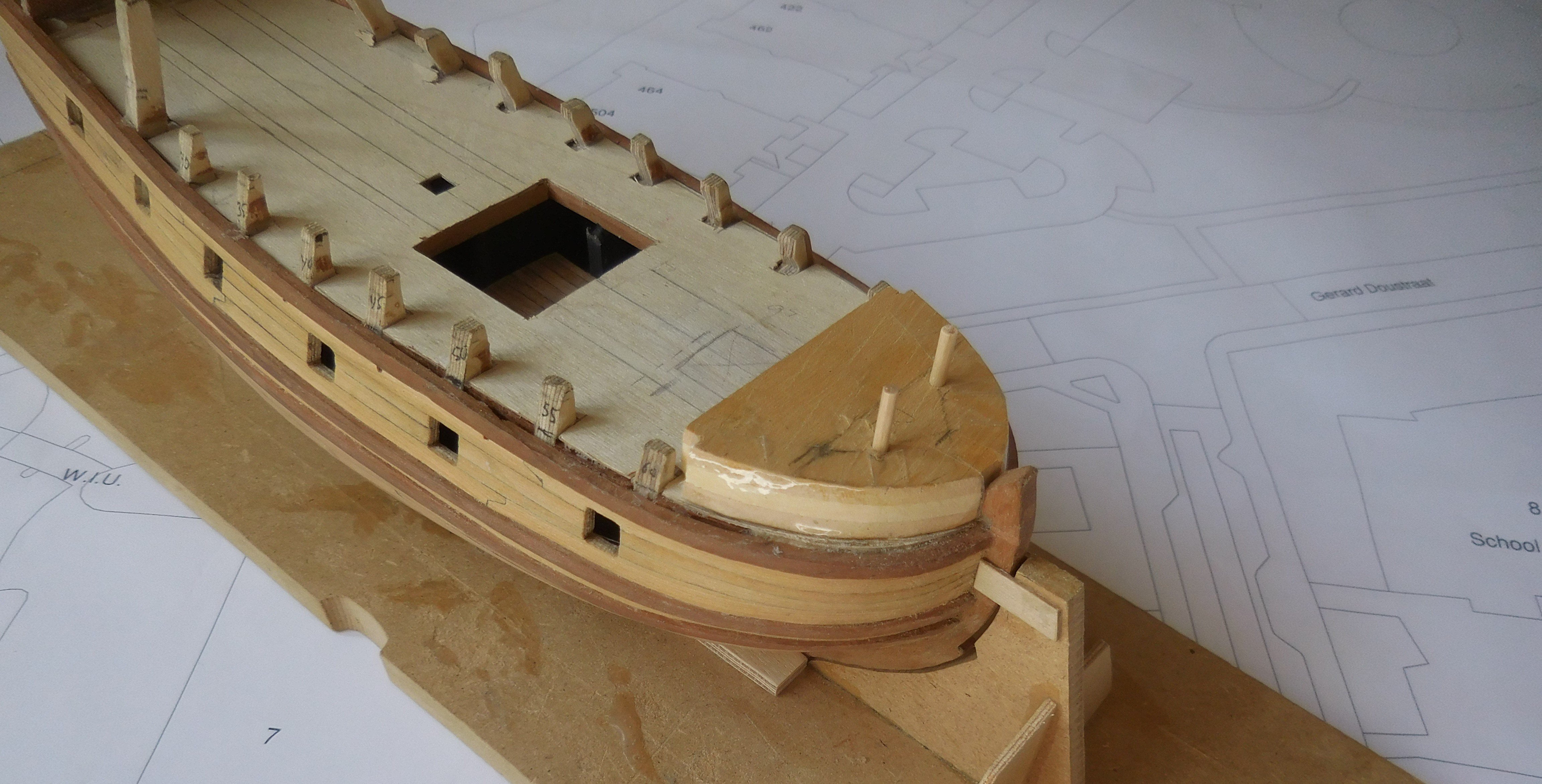
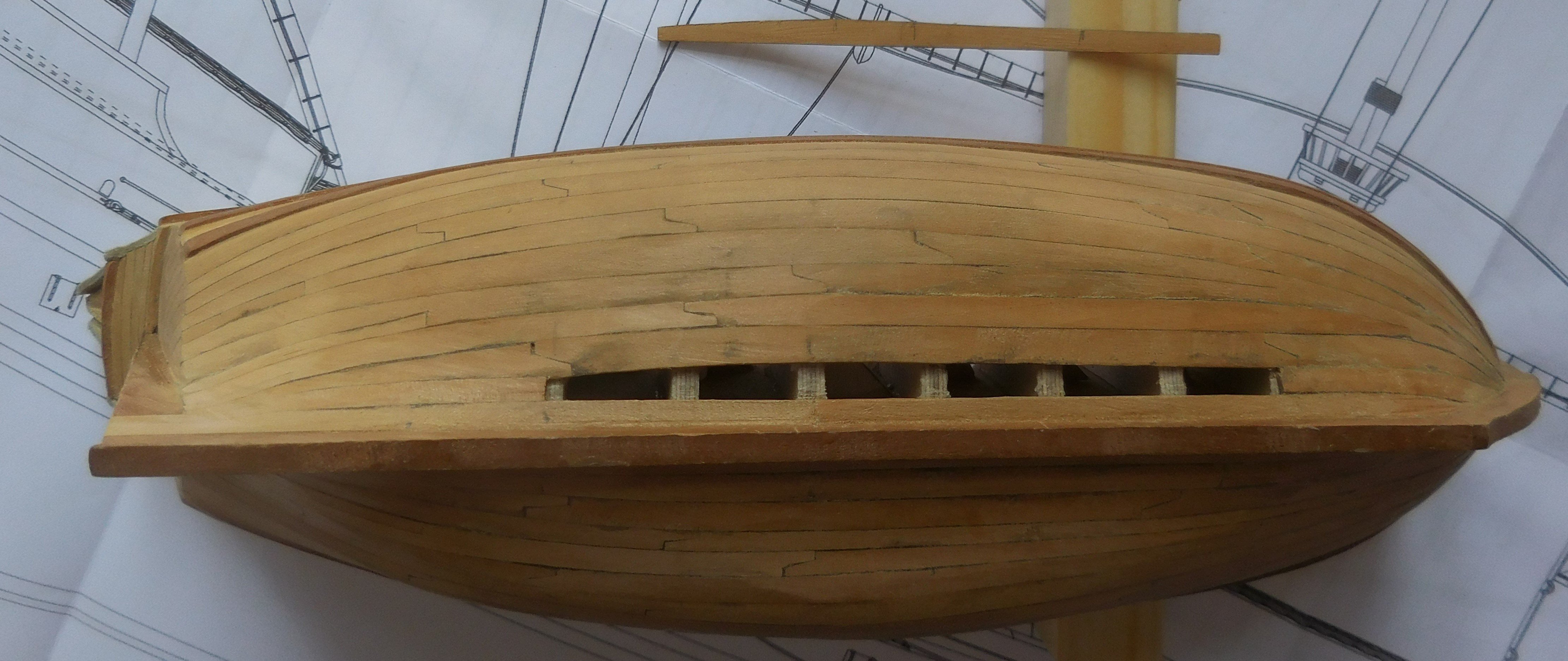
The planks I use are made of pear wood and paranapine. If I want a plank of 3.5 mm wide, I take a board of that thickness and draw parallel lines every 1,5/2 mm. When I saw them out by hand with a fret-saw I have planks of a size of 1,5 x 3,5 mm. After filing and sanding, I am left with about a little more than a millimeter. I do have a fret-saw machine , but it's way too fast and inaccurate. In the picture a number of planks, ready to be attached. In real life, those planks are often no longer than seven meters, so that also has to be taken into account. When attaching to the trusses, it is a matter of fitting and measuring to get a good gradient in width. Especially at the bow it needs to be bent. I then hold that plank in boiling water (or sometimes in my mouth) for a while. To show the caulking seams, the sides of the planks are smeared with pencil in the softest possible hardness. It makes a lot of mess when gluing, but when the whole thing is fixed and I start sanding/filing it all disappears and it looks beautiful. I use a lot of paper tape and elastic to get the planks in place. I never use nails. The result after careful sanding of the hull. At the bow, the lower planks will become sometimes too narrow at the end. So two planks have to be replaced by one plank which can be seen here. And here at the stern sometimes one plank had to end in two planks. After that work, it was the deck's turn. First, a deck of 0.6 mm thick plywood, which would serve as an underground for the planks. The places of six king planks were drawn on it. In the deck, they provided a strong longitudinal connection over the rafters, and were about twice as thick as the deck planks. In the end, there is not much left to see because the top is sinked down between the deck planks. On the deck, the places are cut out for the masts. The large hatch, which will soon consist of two grid hatches, has already been cut. There will be two more hatches in the deck, but since they will be closed I didn't make any holes for them. What will also has to stand on the deck are the windlass, bitts and bitts with cross-pieces. The windlass itself can function very well as an anchor bitt for small ships. Hoving places the windlass directly behind the foremast. In the Dutch city Harlingen a replica is built of this ship on which the windlass stands a long way further. In the 17th century description of shipbuilding from that time: "De Nederlandsche Scheepsbouwkonst" by Cornelius van Yk (1697) it is made clear on page 112 that no anchor bitt is needed for small ships and that the windlass can be used instead of a capstan. Section of page 112 in the book. Once the slab was secured under the deck, it was time to make the bulwarks. Because the bulwarks tilt slightly backwards everywhere, it formed a problem at the bow. I hadn't made any plywood struts there. On the bow I now made a mold that formed the right angle for the bulwark at the edges. To prevent the planks from gluing themselves to the mold, I covered it with cello tape. Wood glue does not adhere to them. Furthermore, the mould had to be able to slide backwards when unloading because the deck is wider there. After attaching the planks of the bulwark, the mold could be removed. The two small holes that were needed to secure the mold later disappeared under the deck planks. The bulwark is three planks high, but the construction is sturdy enough to stand in that shape without a mold. This was followed by the removal of the plywood trusses. I broke it down with a pair of tongs. This was followed by a precise job of filing the stumps that remained in place on the same hight of the deck.


-
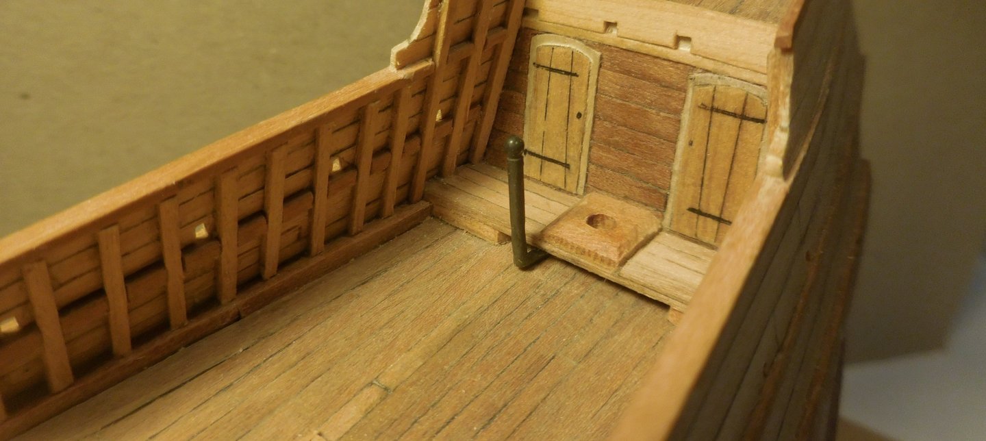
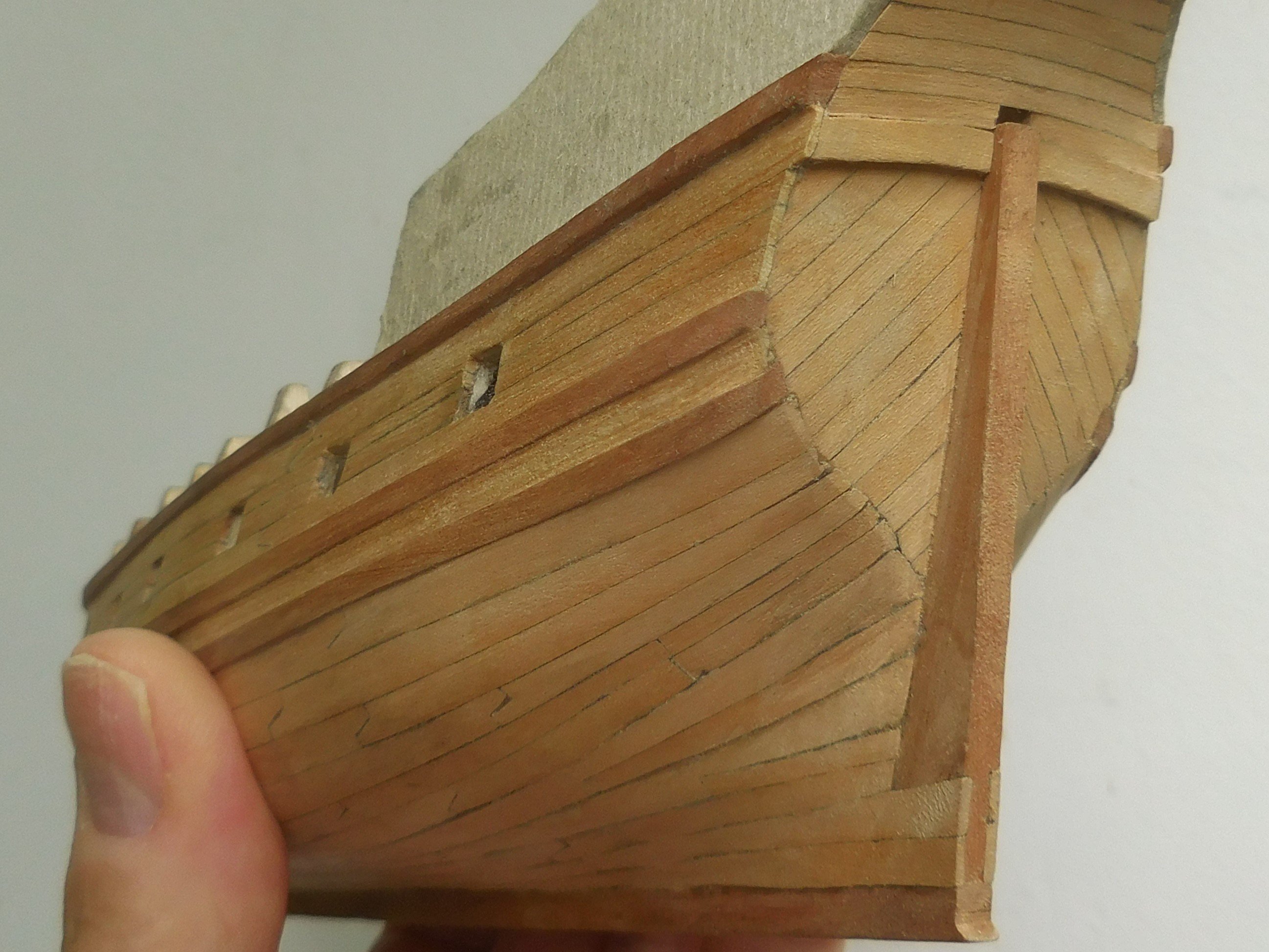
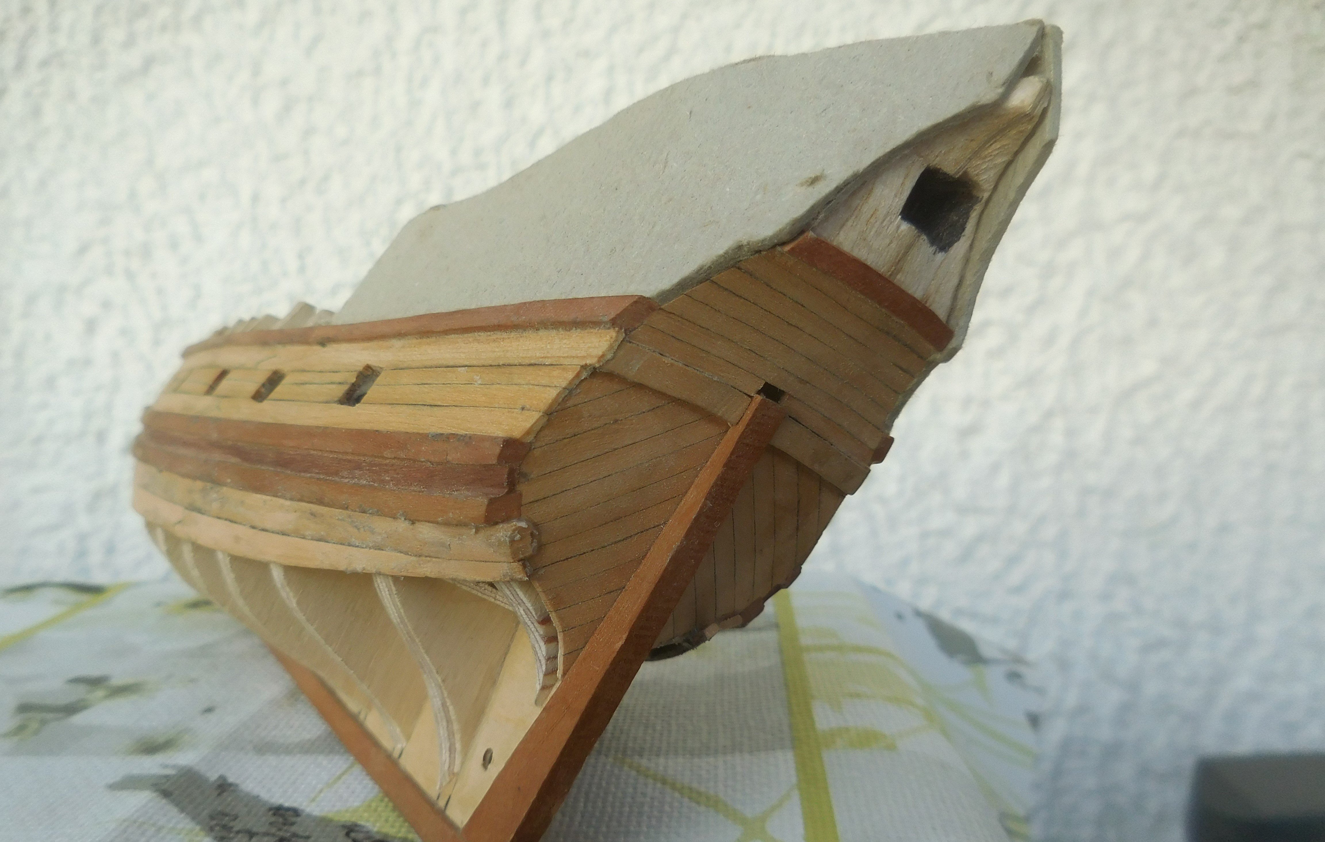
The cabin was fitted with two doors on the deck side. Doors and planks (veneer thick approx. 0.8 mm.) are glued to a piece of plywood of one mm. thick. The wall of the cabin is also a truss mould for the further construction at the rear of the ship. At the location of the future gun ports, I made the necessary openings in plywood. The front gun gate has not yet been made here. It is positioned in the curve of the bow and appears in a closed state when the hull is finished. Also, the top wale has already been installed here. To protect the underlying construction of the superstructure during the planking of the hull, I made roughly both sides above the upper timber from cardboard. The hull is already partly equipped with planks. The part between the upper two wales, in which the gun ports are placed, are made of paranapine. The wood is fine-grained, not too hard and easy to bend and work with. The planks are a maximum of 3.5/4 mm. wide. Which equates to about 33 cm in reality. The curve above the transom is now also provided with planks. The opening for the rudder pin, the tiller, has been cut out. The joints of the planks are provided with lip weldings. It is important that the entire connection is fitted together for two planks outside the ship. If that is exactly right, they are all different, then one of the planks is attached and the other is provided with a lip seal, at the other end, with a third plank on the other side. This second plank is then attached and the entire length of the ship is finished. Planks on wooden ships were never lomger than 7 m. The stern was made before the planks were attached. The planks go over it. The very dark planking between the two wales were too dark. I removed them and replaced them with pear planks. The part between the upper wales was finally closed. You can clearly see how the lip welds are placed between the planks. One of the mysteries of such ships concerns the large number of gun ports, sixteen of them. If you count that there were 17 men on the ship, it is hard to imagine that there was a cannon behind every port. In those days, no seabattle was fought by firing all the guns at the same time from the broadside of the ship. Rather, we should see that as skirmishes with a few very light artillery pieces, at most 3 pounders, and muskets. The large number that appears in many prints from that time (not only in the account of Barents' voyage) with the mouth of a cannon from each gate should rather be seen as an interesting depiction of a ship. It is not possible to find out how many cannons this early Pinas had, perhaps at most about four. They were small cannons on mostly three-wheeled carriages. Small fire mouths, rear loaders, which stood with a gaff in a hole on the side wall were also used. My assumption is that those many gun ports could also have served well to row the ship in case of an emergency. The ship is very small and can certainly be moved with oars. Somewhere in De Veer's report it is also said that the ship is being rowed. Whether it means that it is pulled by a rowing boat or that it was rowed independently will never be clear.


-
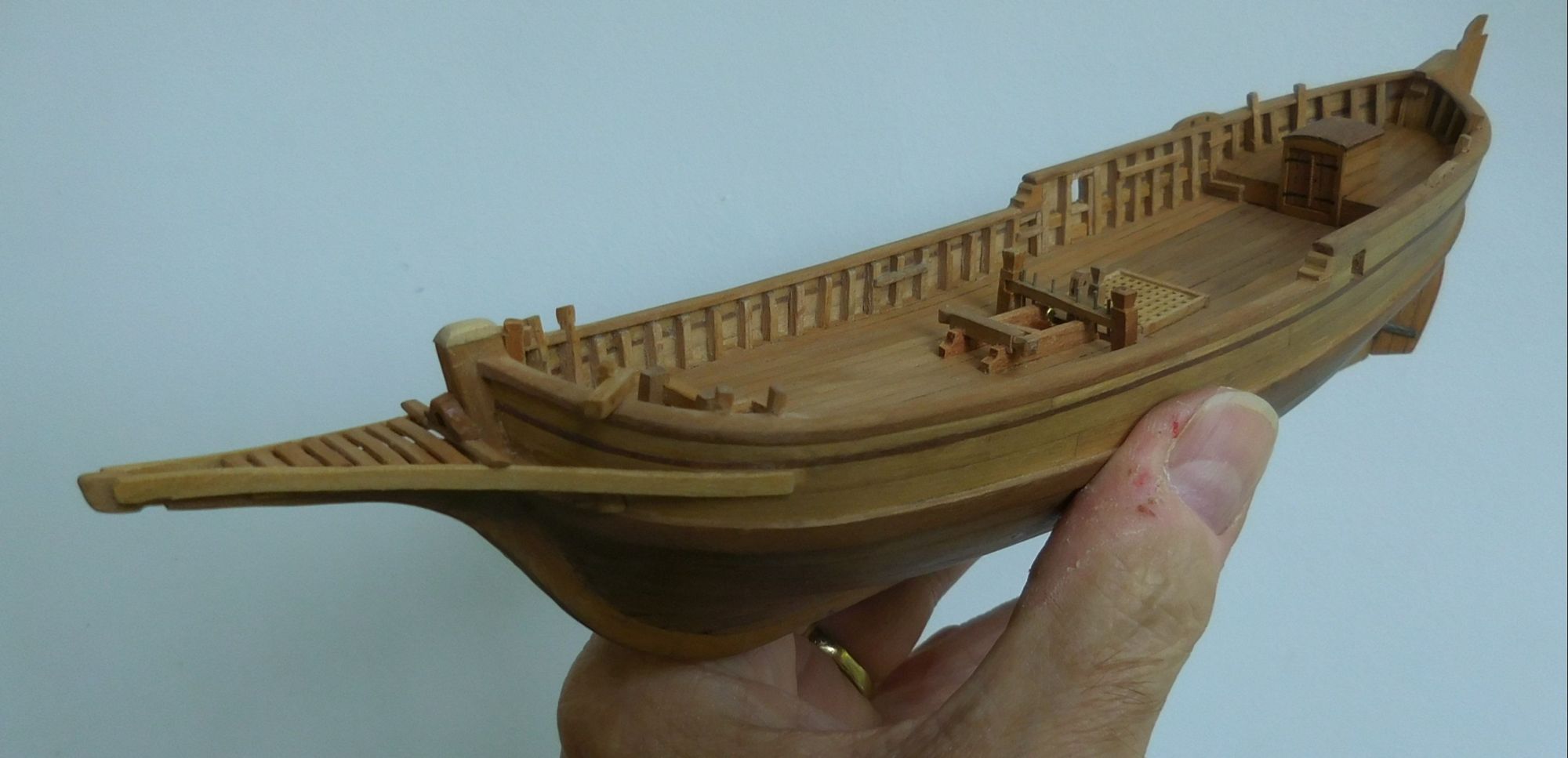
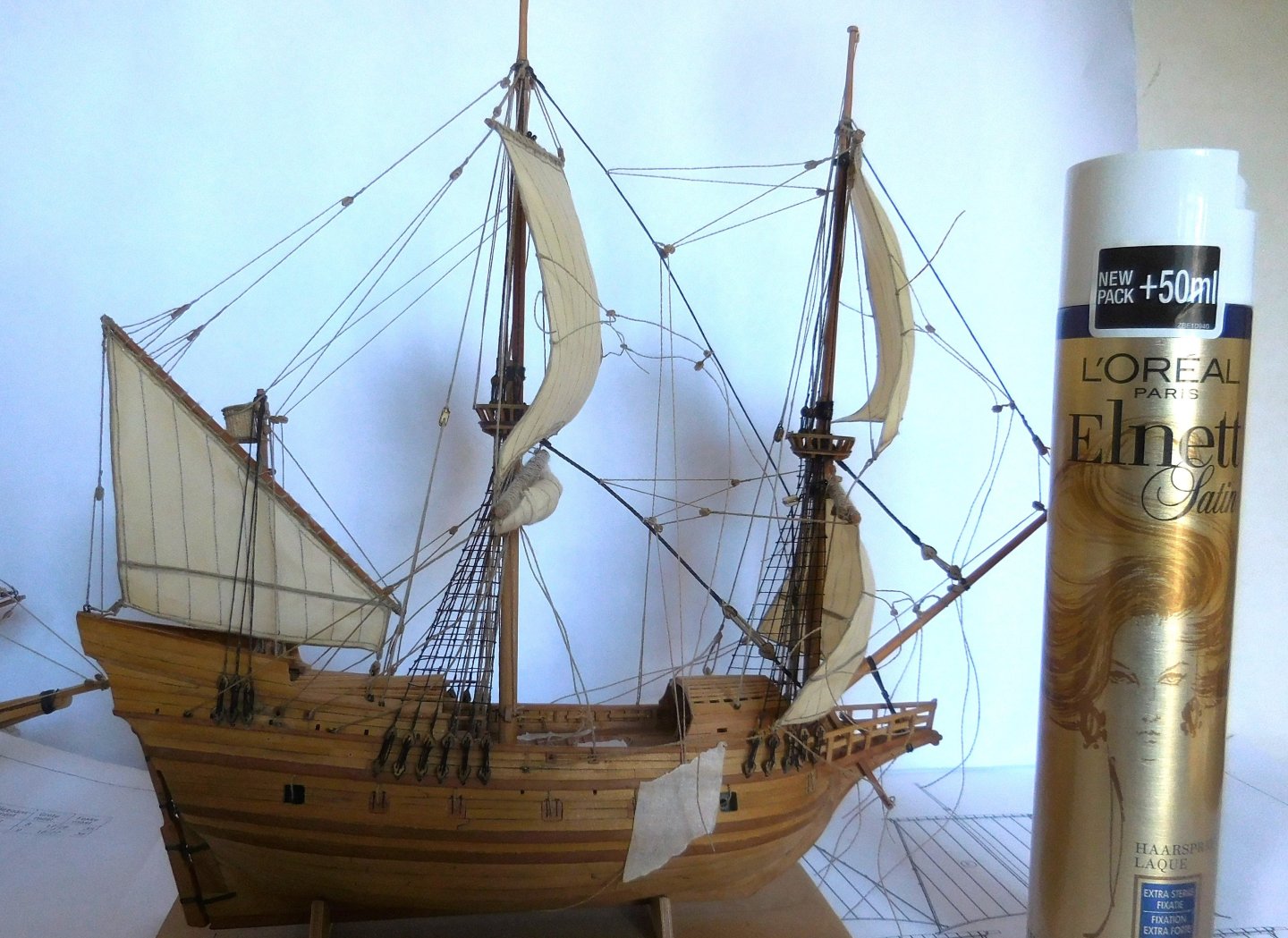
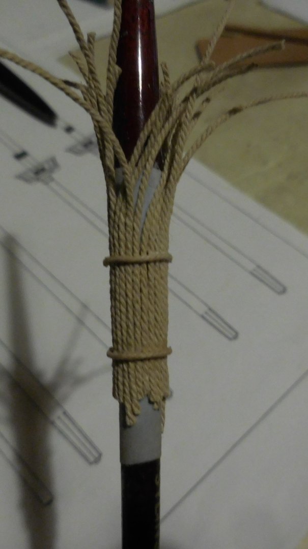
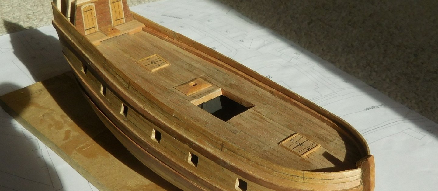
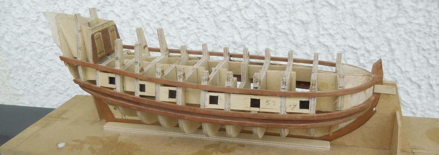
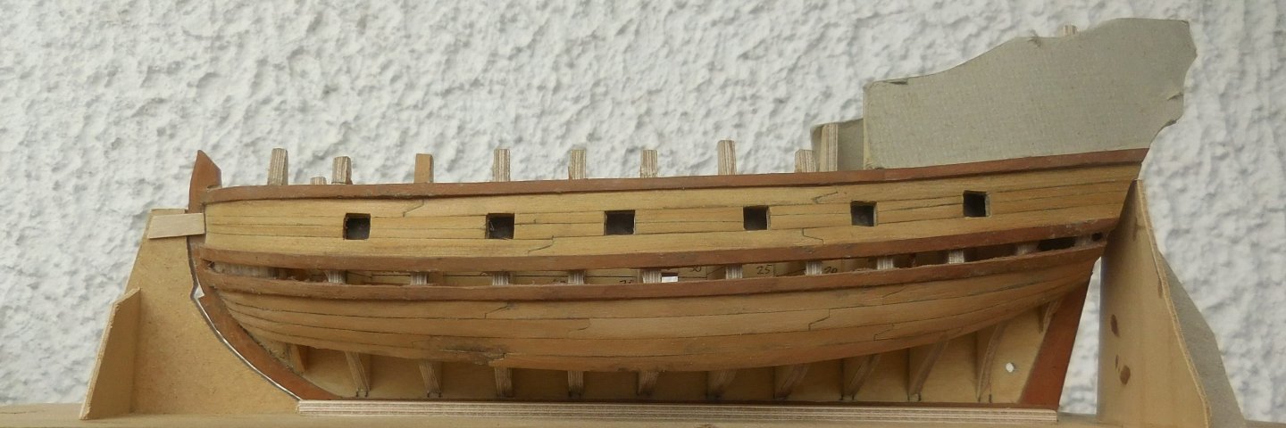
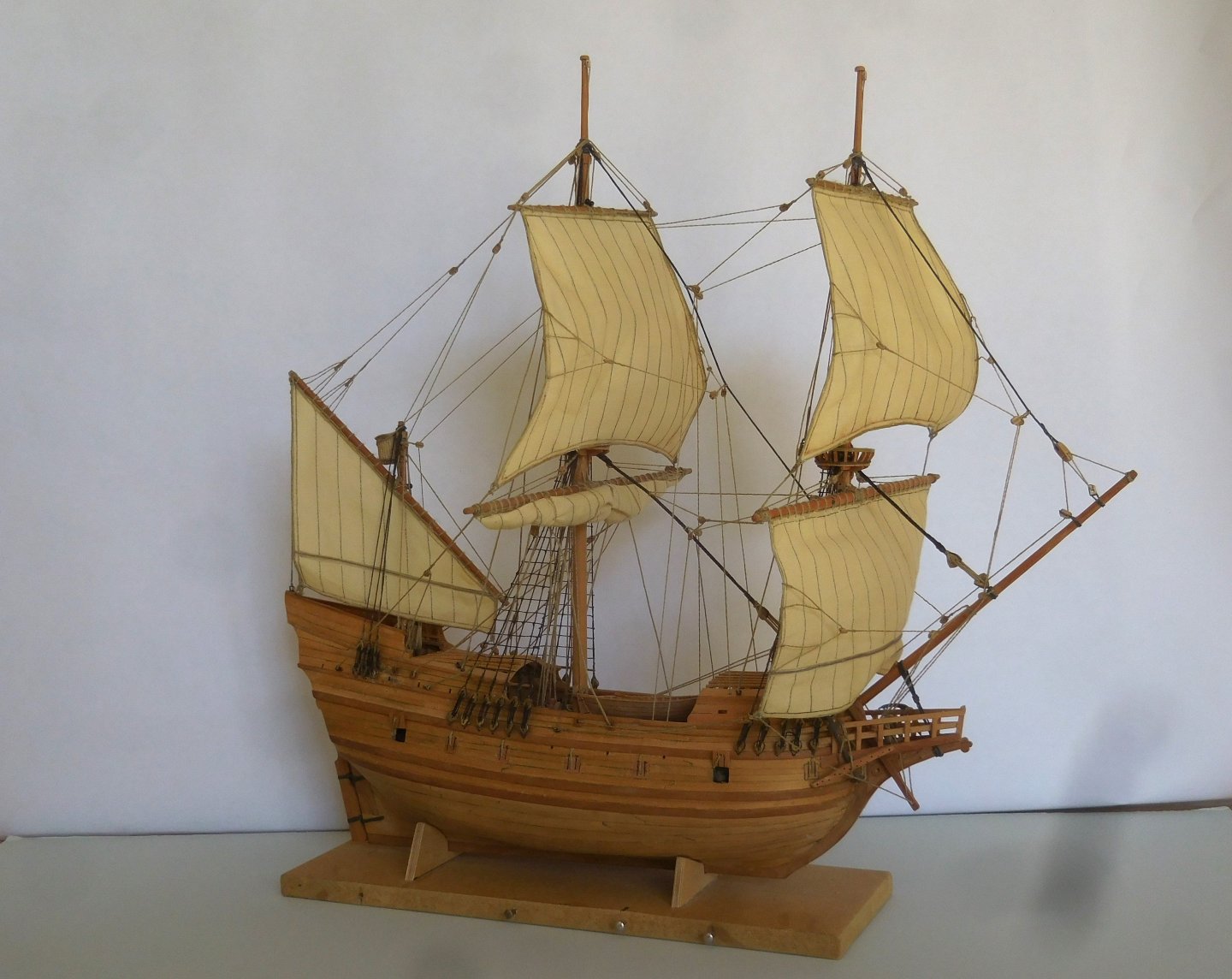
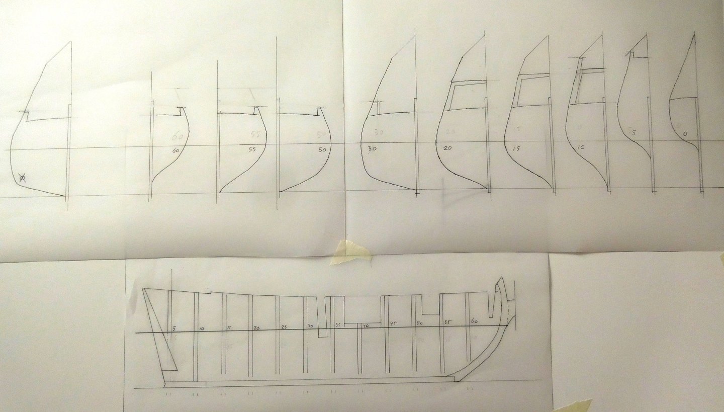
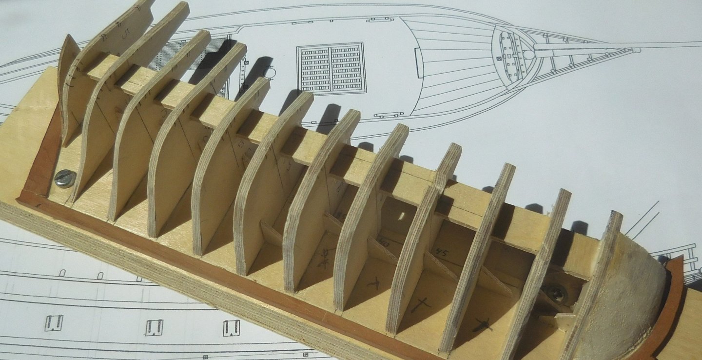
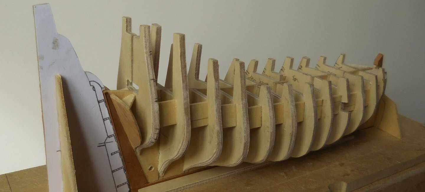
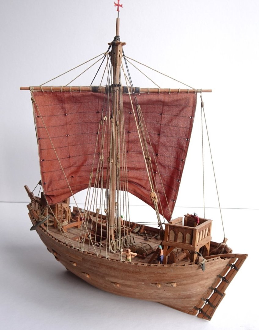
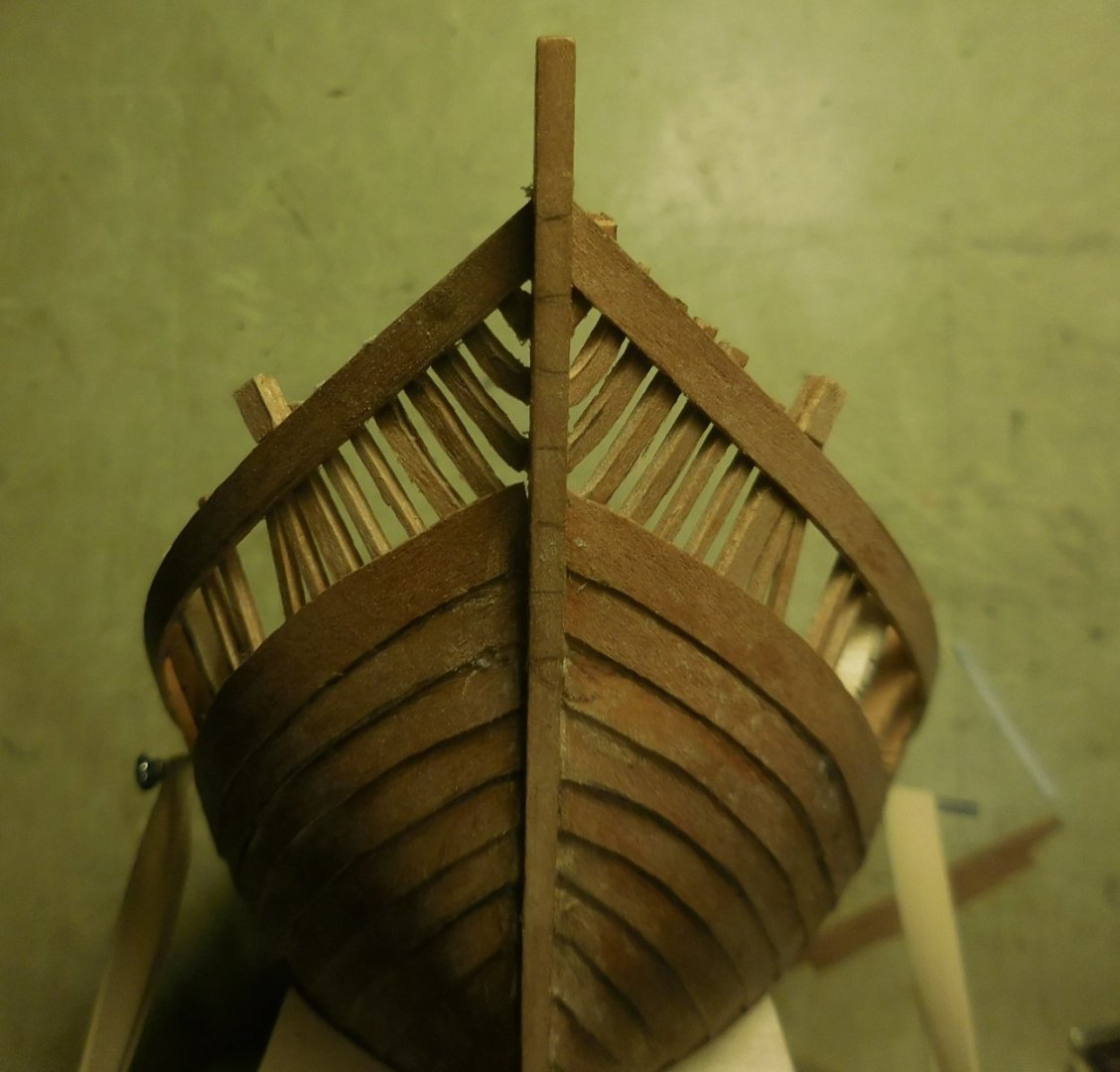
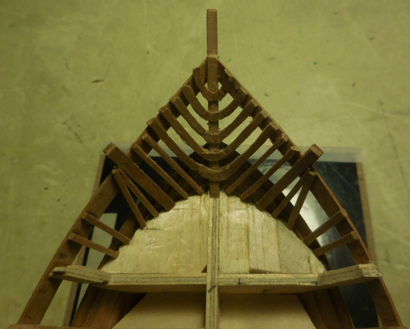
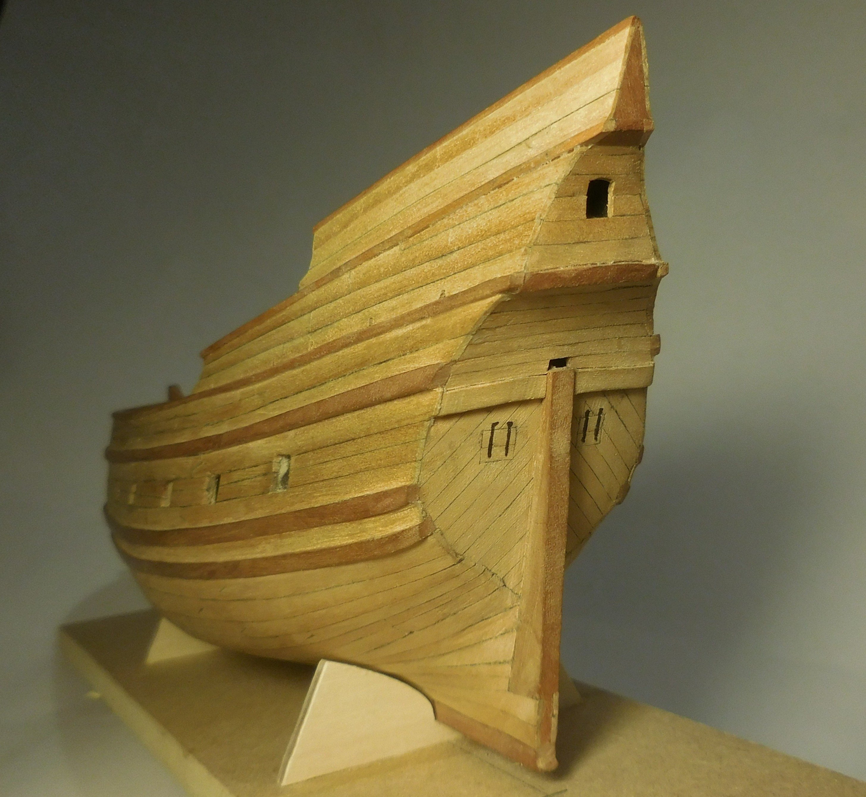
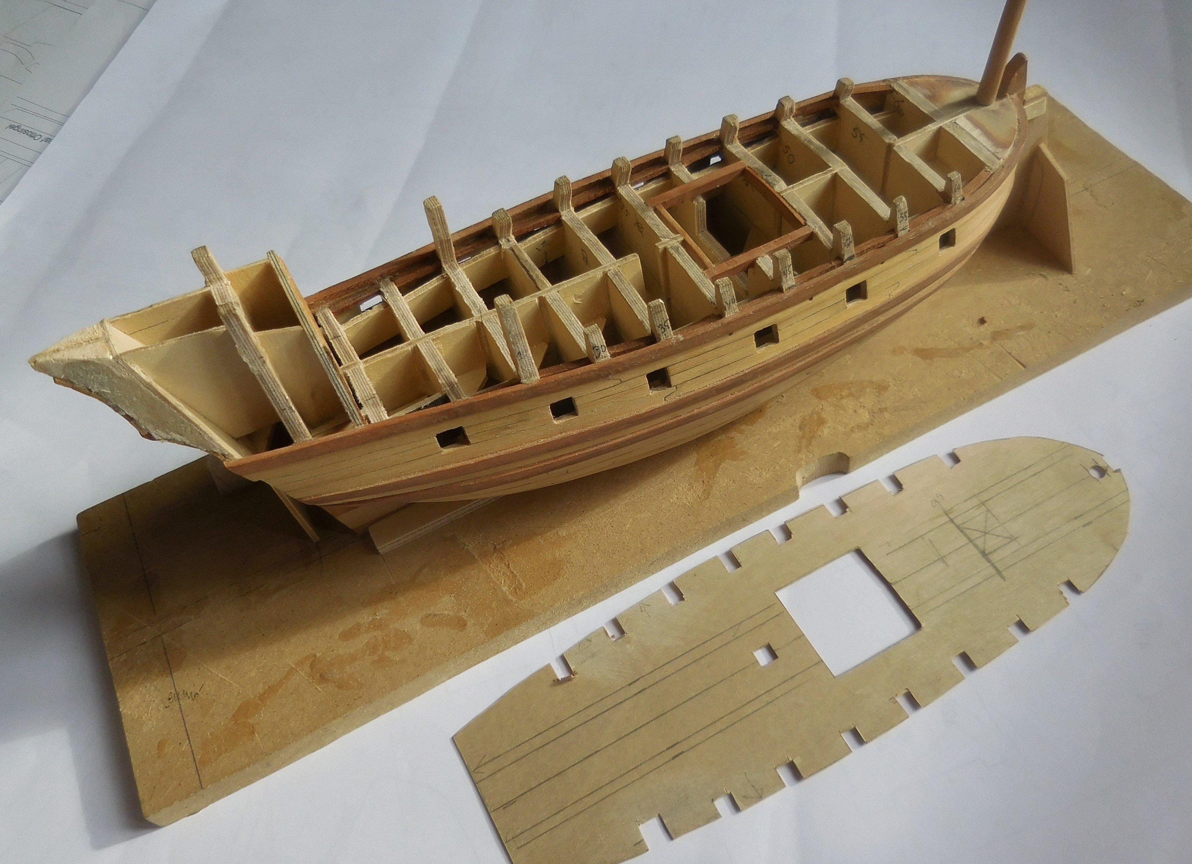
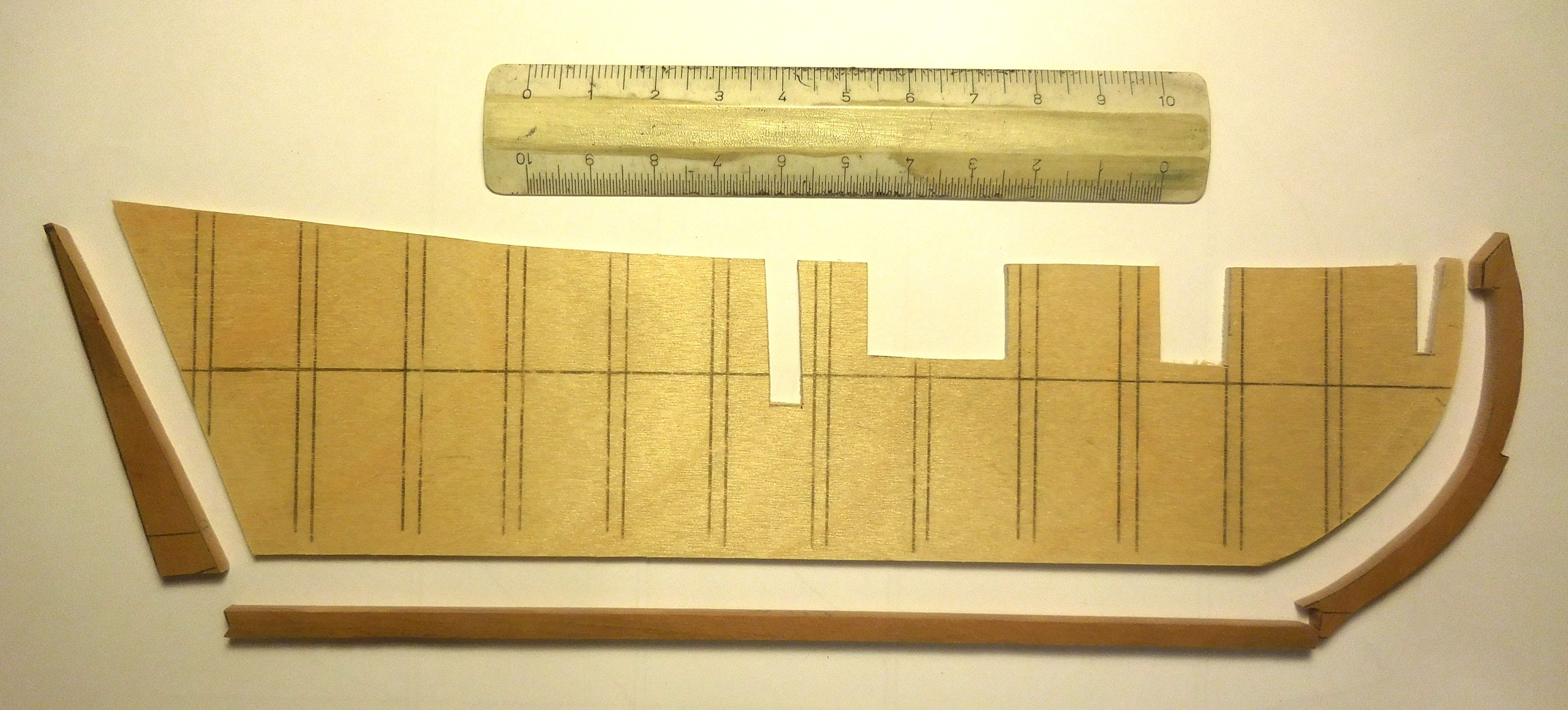
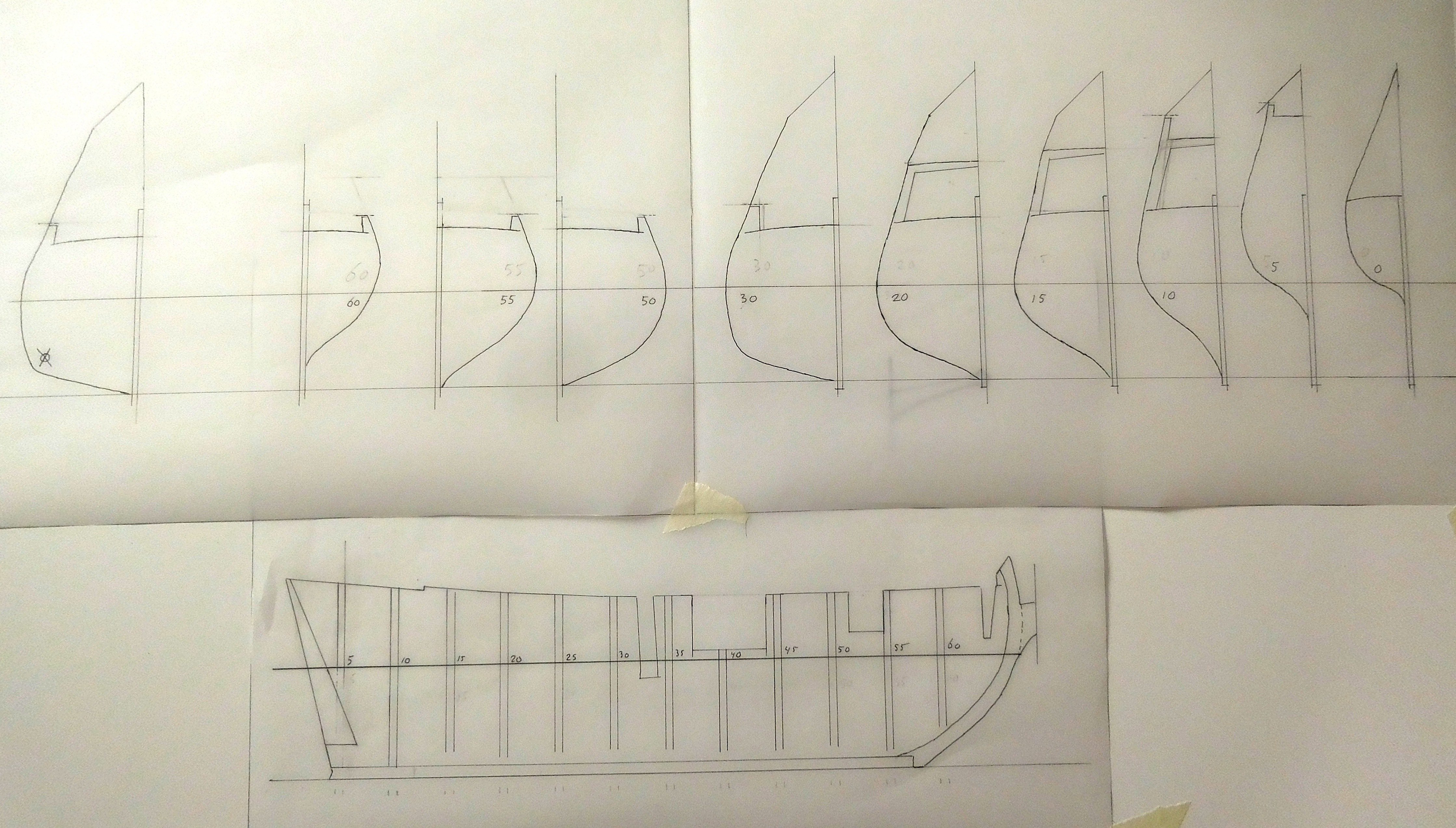
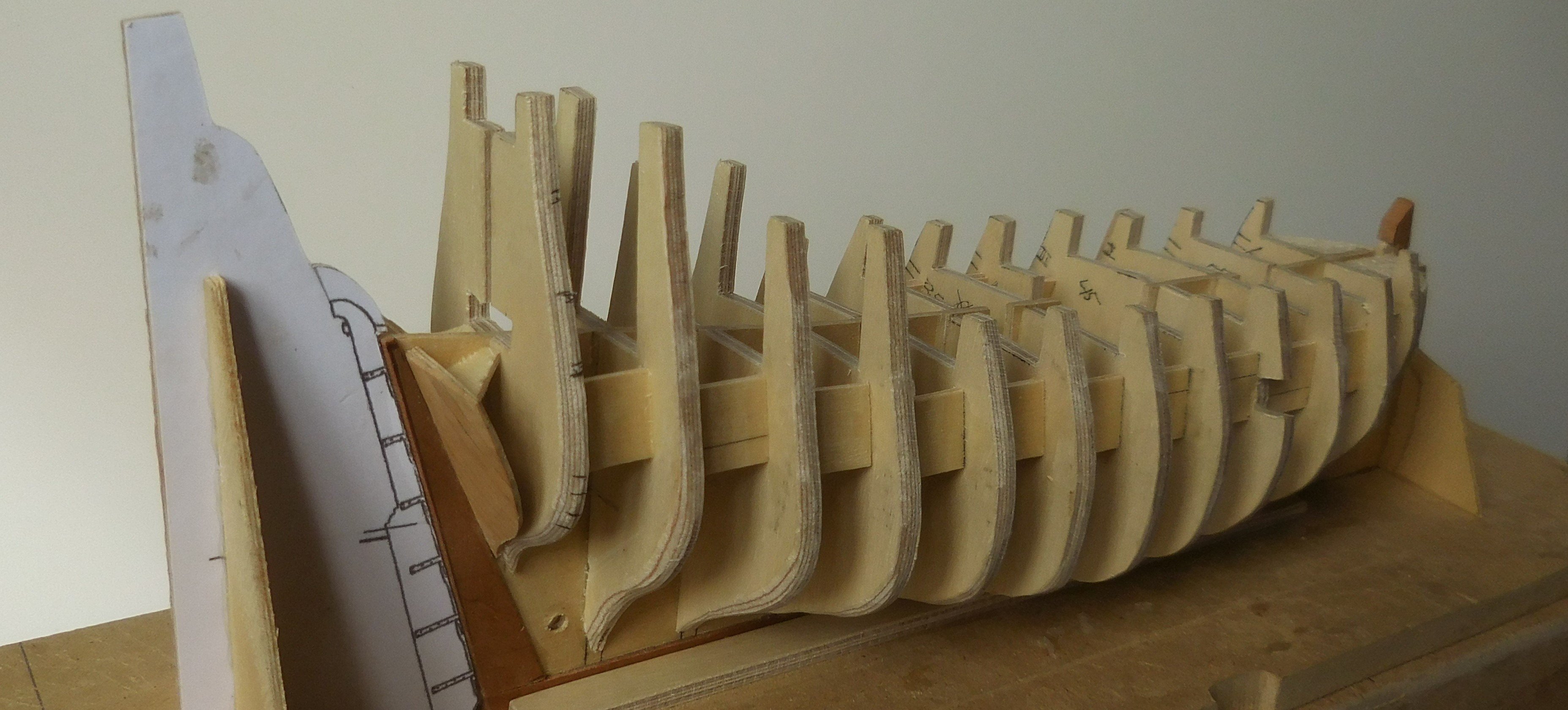
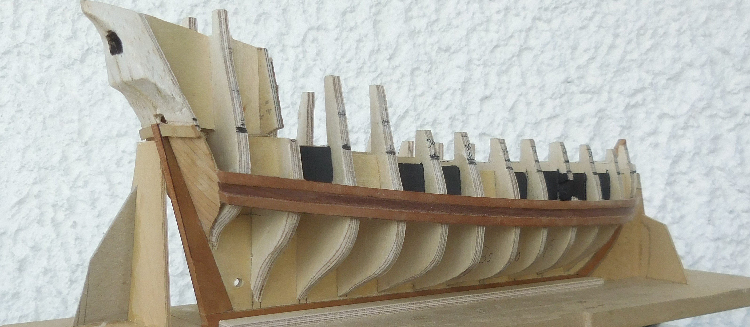
In this topic consisting of several episodes, I am going to tell you something about the construction of this ship. Although it is very small in real life, and many times smaller on a scale of 1:87, it was a fairly difficult job to get it done and it is based on a lot of research. At the beginning of June 2018, I started building a model of the ship on which Willem Barents sailed to Nova Zembla in 1596. The Northern trade route had to be found, but that failed and Barents had to spend the winter on this island in the Arctic Ocean with 16 other crewmenbers. But the year after they returned to Holland. Shortly after this event, drawings were made of this ship that served as illustrations for the travelogue of Gerrit de Veer, one of the members of the crew. The two ships of Heemskerk and De Rijp. The commander was Barents, who was on Heemskerk's ship. The names of the ships are not mentioned anywhere. As a result, reconstruction attempts were made to find out what the ship looked like. Ab Hoving has written a book with fine detailed reconstruction drawings, which form the basis of the construction of the model with which I started. By the way, I am not supposed to call this model “the ship of Barents”. I never build models of ships that had a name, but only build ship types. In consultation with Ab Hoving, we decided to call this type an "Early Pinas". A Pinas is a very well-known type that was built frequently, especially after 1600 in Holland. This ship dates from just before that time, around 1590, and at that time a number of later inventions had not yet been applied. Since I have built more ship models on HO scale, so 1:87, it was logical that I would do that again. The models can then be compared in terms of size. Installing the rigging took a lot of time, also because it was all still unknown territory for me. In the previous 40 years, I did long-term research on Latin-rigged ships that sailed around the Mediterranean, and built models on a scale of 1:87 as a result of those studies. The rigging and hull construction are vastly different from square-rigged ships. This was my first square-rigged ship. At first I looked despondently at the drawings of the rigging, but after a while I understood all the functions. Repeatedly, I had to remove it again and try again. Ab Hoving was always ready to provide me with the necessary advice. His help was indispensable because he had also carried out the entire research on this ship and had described it in his book; HET SCHIP VAN WILLEM BARENTS. Een hypothetische reconstructie van een laat-zestiende eeuws jacht (A hypothetical reconstruction of a late sixteenth century yacht).ISBN 90-6550-772-8 Many of the techniques that can be found here are also described on my website; www.constantwillems.nl And the same applies to this model; it is a reconstruction, so there is a chance that the ship looked different in details. The construction of the hull A start was made with transferring the trusses, obtained from data from Hoving's drawings, to paper. Those drawings are on a scale of 1 : 75 and it was a simple action to take those drawings to a copy shop where they were transferred to scale HO., 1 : 87. Like all my models, I built this boat mainly from pear wood. Part of it is made of paranapine. It is built on rafters of plywood thick 3 mm. Actually a bit too thick but I tried to imitate the lip welds of the original construction and then a wide enough surface is needed to make those welds on those rafters. The trusses as I first drew them I always work with half-trusses, as can be seen in the drawing. When all the half-trusses on the port side are glued to the central truss, all imperfections on that side can be repaired very accurately by filing away excess material. When everything is satisfactorily secured, I start with the other side. To this end, moulds are made from the already glued trusses, which are carefully sawn out and glued to starboard. Thus, everything is completely equal on both sides. The longitudinal truss is made of plywood 1.5 mm thick. The bow, keel and stern are made of pear wood. These parts were glued all around against the longitudinal truss so that on the port and starboard side there is still above those parts 0,75 mm to support the ends of the planks. The locations of the numbered half-trusses are indicated on the longitudinal trusses, as shown on the drawings in the book. Because the longitudinal truss is quite thin, it can bend easily, so it was screwed onto a board and I added small distance partitions between the rafters. At the bow arrived a filler piece of balsa wood that had been filed into the right shape to give the planks at the bow the correct shape. After unscrewing the longitudinal truss, it turned out to be an indeformable unit and the other rafter halves could be glued. When everything was in place, on both sides of the longitudinal bilge, I made the stern. The construction has quite a few bends and to make that easier, a mold was placed on the work board to make the right shapes. The top piece was made of balsa wood. The black hole is the interior of the cabin where a window was later added. The lower timbers have already been installed here, which already gave the framework a lot of strength. The transom is of one mm. plywood with the planks glued on top in the right pattern. Later, the openings were added. The support boards between a number of trusses are painted black. They are behind the open, or closed, gun ports. The struts for the bulwarks were made of plywood. This is only necessary to attache the planks above the deck which form the bullwark. Once they are glued on, the plywood pieces were carefully removed and then be replaced by the struts in the correct dimensions and material. The top of the bulwark was called the rahout (Dutch word; ra is yard, hout is wood). On an early pinas it was customary to lower the yards on the bulwarks in order to stow or strike the sails. This is how the name rahout came about. On later ships, the sails were stowed or struck on the hoisted yards.


-
My Norwegian is also not very good, but I think Steve is right. I have a dictionary in ten languages, for maritime expressions. Norwegian is not the language which is in the book but only Danish. But in this language I could not find the meaning of your word.
-
Can you post an illustration of this item. Ik do not know what a Gjoa exactly is.
-
Thanks for all your positive reactions!
The shipmodel I built was the skratch built ship of Willem Barents, scale 1 : 87. He sailed with it to Nova Zembla in the winter of 1496. But I do not give names to the models, I only build types of ships. So this one is an early Pinas. After 1500 the Pinas was a very common ship, but before 1500 it was somewhat different. Important inventions at the end on the 15e century were yet not practised on this vessel from 1496.
I always do a lot of research before I build my models.
-
Ship in trouble by Ab Hoving - FINISHED
tartane replied to Ab Hoving's topic in - Build logs for subjects built 1501 - 1750
Hello Ab, Nice to see you here on an other forum. I am going to post some topics, which are well known by you I guess. Constant -
Well done so far! I am intersted in the construction of cogs as you can see in my last topic. The rigging is different than some nowaday pictures of cogs show. I did research on this subject and discovered a kind of rigging that is similar to ships with latin sails. I would like to advise you if you want to, Constant
-
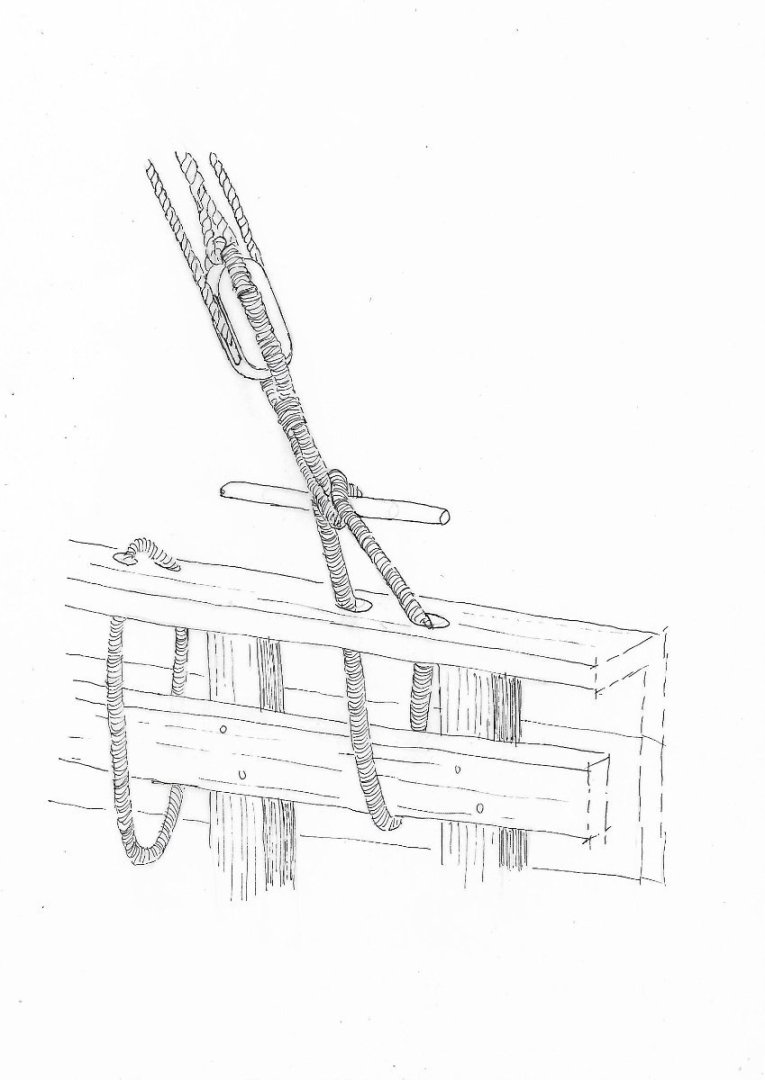
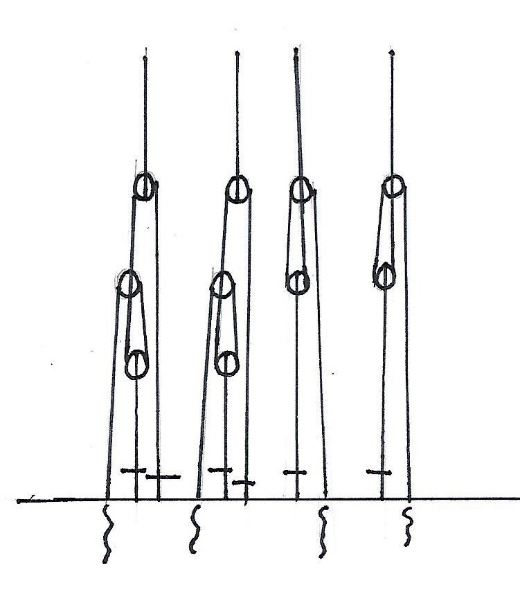
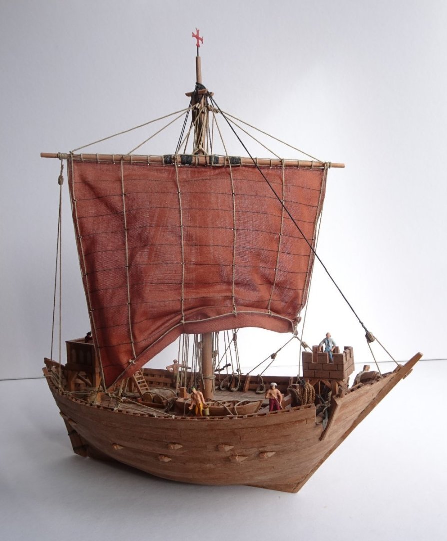
The rigging. The rigging is less complicated than the rigging on more masted ships, but is basically the same. A big difference is the absence of lanyards and deadeyes. During my research I came to the solution that this construction is an invention which dates from the first half of the fifteenth century. Original mediaeval pictures show everywhere an other construction which is surprisingly the same as used on ships with latin sails, which were used until the last part of the nineteenth century. This cog was build in 1320, so long before the invention of lanyards and deadeyes. One of the reconstructed cogs was build in Kiel in Germany. While testing its sail capabilities it appeared the ship could sail up to 70 degrees by wind abeam. In this position the sail would grate over the shrouds. The shrouds on that ship are equipped with lanyards and deadeyes, which I believe is not correct, so the shrouds could not be removed in case of grating. Shrouds on ships with latin sails can be removed while sailing. A part of the shrouds on leeward can be removed while the ship is sailing abeam. This is possible with the help of the construction as drawn in the sketch nr 1. A stick (Dutch; knevel) can be pulled out in the connection of two parts of the shroud which both end in a noose. On both sides of the ship are mostly four shrouds as drawn in nr 2. The shrouds windward can of course not be removed, but with some of the shrouds leeward it is possible. 1 2 The model without the yard, but with the shrouds. On port-side the four shrouds are all fastened, on starboard only two. The other two are hanging alongside the mast. In this case the wind will come abeam the portside. This construction is on ships with latin sails always usual, but it is also possible on cogs. Old mediaval illustrations of ships show this solution. Ships with latin sails have a different rigging because of the possibility of setting the sails and yards in other positions which move around the foreside the masts. But the shroud construction is the same as on cogs. It is obvious that ratlines are impossible with this type of rigging. Ratlines in shrouds can not be found on ships before the first part of the fifteenth century. The rest On the model I made two anchors. Made of brass. I sawed them from brass plate, thick 2,5 mm. After filing and sanding in the correct proportions, blades of thin brass, were soldered on it. After that I painted them in colour Matt 46, from Revell. All iron pieces on the models I make are painted in this color. Never black. The sailors on the model are from “Lehman HO pirates 90-2025”. Usually I do not place figures, but this model goes to a museum here in town. For visitors it is in this way easier to compare the human proportions. I never paint my models, only the sails. The finished model gives an impression of how those ships looked like. It is a reconstruction, so there always will be the possibility of other opinions. The following pictures give an impression of teh finished model. Cogs had an unsusual construction of the hull. The ends of the beams inside the ship came out the side of the ships hull. This can be seen on the next illustrations. u
.thumb.JPG.58f93355d38b98a2007c44328bf7b674.JPG)
-
Hi James, Thanks for your compliments! I made several historical boats which require a lot of research. Ik build them all on the same scale so it is possible to compare each other. On my website you can find some other boats; www.constantwillems.nl Constant
-
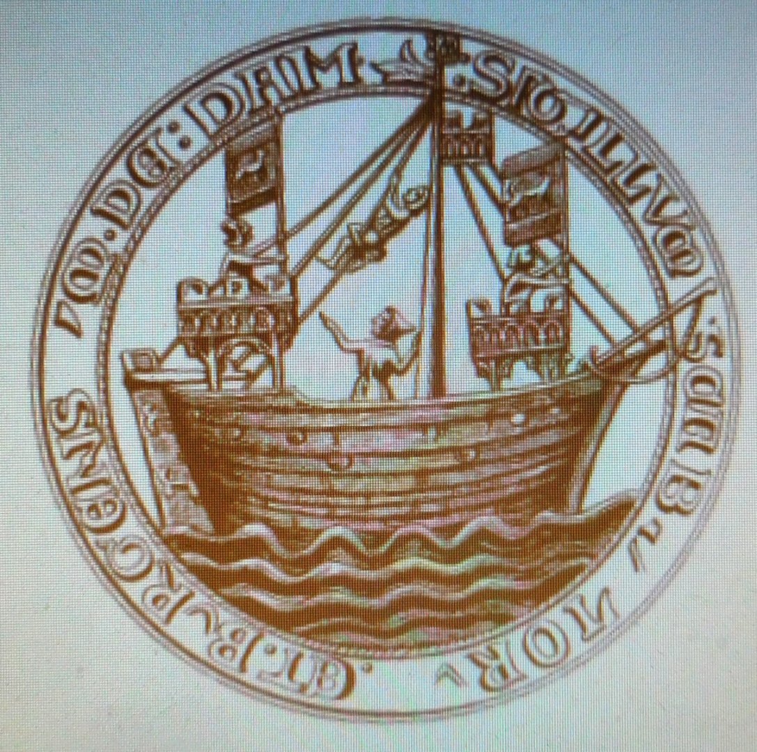
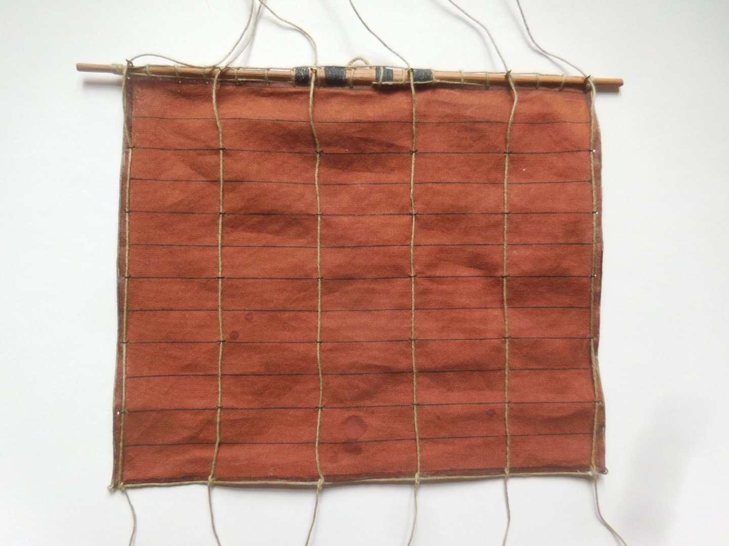
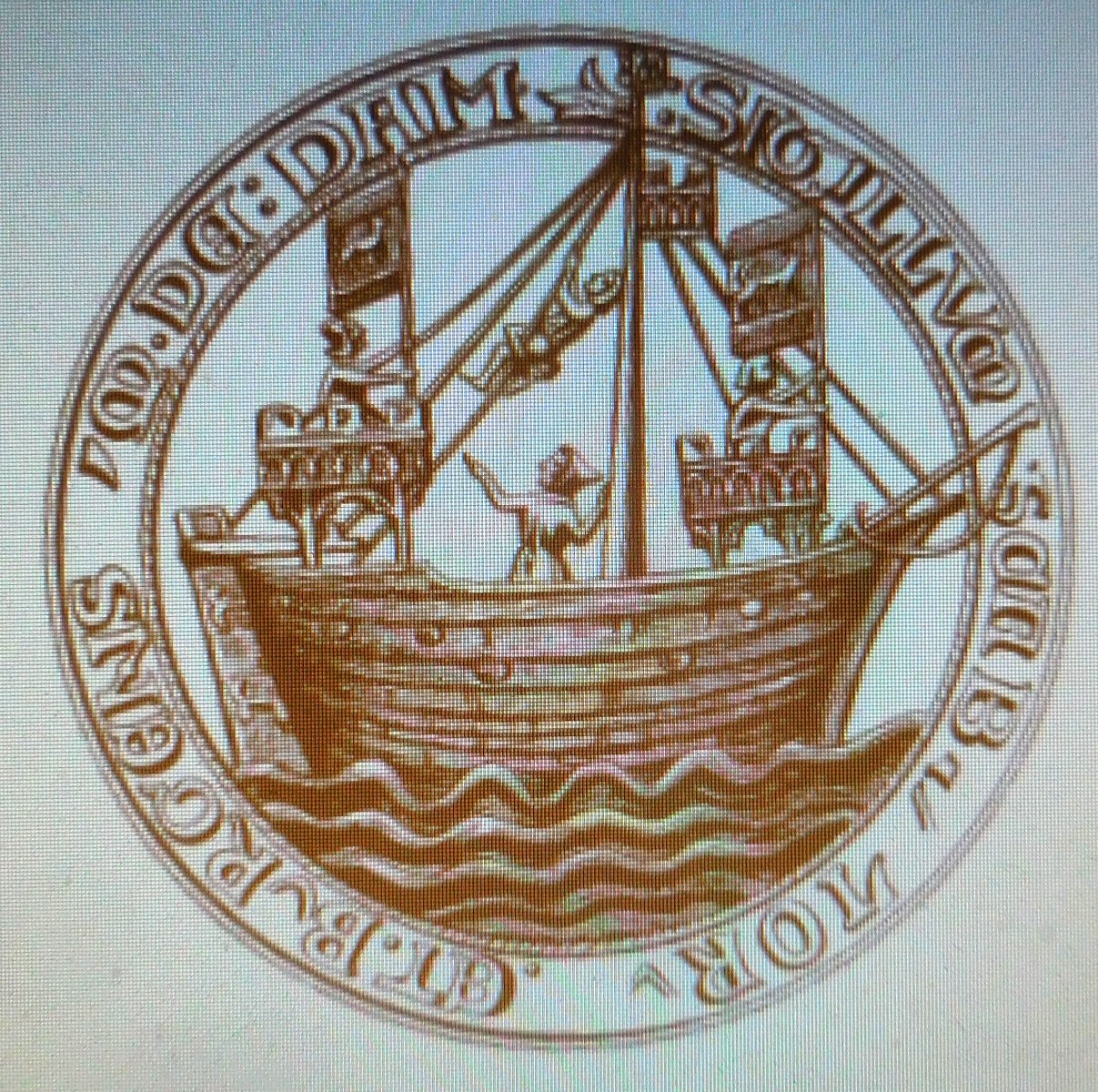
The deck On two places I made openings in the deck. The deck itself consisted of a frame of beams with were formed in a rectangular pattern. Most rectangulars were planked, but a number were hatches used for loading the vessel. Probably these hatches were caulked during the voyage, to prevent overcoming water in the ship. The walnut shape of the deck which is characteristic for all cogs in that period. In the bow a part of the railing was missing. Probably to guide the anchor cable in a low position. This prevented damage on the upper part of the railing. A cleat on the foreside prevented damage of the anchor-cable. Th castles. In the wreck were remnants of the vertical beams which once supported a castle in the stern.These wooden castles were common on these ships. The ships company could defend themselves against attacs during the voyage. In none of te wrecks of cogs were sufficient remnants found of such castles. So we have to look at old illustrations on coins and document-seals of the cities which committed trade with these ships. Fortunately there is a large number of these old seals, on which castles can be seen. Sometimes there was only one castle but other seals show two of these structures. I chose for two castles, according to the seals of the city of Damme 1300 and the seal of Rye 1400. On the reconstruction on paper in the archeological publication are drawn two castles. The castle on the stem and a very large castle on the bow. The last one could impossible have stand on this place. It stands in the way of the sail when the wind blows in it. On all seals on which two castles are depicted it is obvious that the castle stand as far as possible near the bow, sometimes even on the bow. Two document-seals with cogs. Above the seal of Rye (1400) and under the seal of Damme (1300). I chose for these constructions. The back of the tower on the bow must stand at least on the half length of the yard before the mast, otherwise the sail could not be braced in the proper position during sailing. The mast and the yard. The mast and the yard were not found on the wreck. There are two reconstructed cogs on full scale on which the lenght of the mast had to be calculated. Both cogs are fully documented. So I took the three lenghts of the ships and the two lenghts of the masts of the reconstructed ships. After some calculations I found a hight of 17,3 m. above the deck. The construction of the mast is exactly as made on the two reconstructed ships. The sail. Cogs had only one sail. How this was made is not exactly known. Different solutions can be seen on the document-seals, but the details are very small and hardly recognisable. I did some research on larger illustrations, mainly before the year 1400. Even pictures dating from the Roman times. There I found ships with only one mast with a very detailed rigging. I decided to use these details on my model. Surprisingly some deatils are the same as depicted on several seals from about 800 years later. The sail I made consists of twelve horizontal strips and six vertical ropes. Each rope is led throug rings on every second horizontal seam and finally attached on the lowest seal. When you pull the ropes the sail will fold up until the entire sail ends under the yard. This construction can be seen on a reconstructed pre-Roman vessel which sails in the Mediterranean the ”Kyrenia Liberty”. The sail is horizontal longer en verical shorter than the sails which are used on the two reconstruced cogs. On both ships the sails are the results of exeperiments. On my model I used the proportions of the sail which can be seen on old original mediaeval pictures and according to the measurements of the Kyrenia Liberty. For this reason the yard is also very long. Every rope leads through a bloc in the top of the mast and ends on a jeer bitt on deck.
.thumb.JPG.8d7f27d5485b61a4f1cf4106ca0e3cb3.JPG)
.thumb.JPG.07b394813d389c1063d333b37d7261e4.JPG)
.thumb.JPG.c20c640926cc8fdbe805b0b6ef7d7846.JPG)

.thumb.JPG.27a4f9e933a98ed88c64524f46971dc0.JPG)
.thumb.JPG.30c025935702715438da1606ebf15b7d.JPG)
-
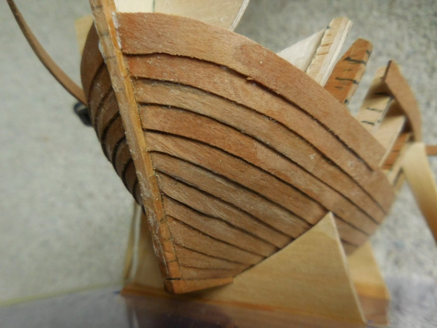
In 2023 bouwde ik een model van een kogge, een schip dat van belang was voor de handel tussen ca 1250 en 1450. Ik bouwde hem, niet vermoedend dat het Stedelijk Museum in Zutphen daar lucht van kreeg. Men vroeg mij het model onderdeel te laten worden van een expositie over de Hanzetijd, waar dit schip een grote rol in speelde. Het verslag ga ik laten zien in drie delen. Ik maak op voorhand excuses voor mijn niet perfecte kennis van de Engelse taal, maar ik koos er toch voor dit in het Engels te doen. Er komen veel termen in voor die niet goed in computertaal in het Engels zijn weer te geven. RECONSTRUCTION OF A COG Scale 1 : 87, Built in 2023 This reconstruction is exactly based on the measurements and construction of an excavated shipwreck in Holland in 1983, registrated; Oz 36, known as Nijkerk II. The results were in 2021 published by the archeologist Karel Vlierman in 2021 ; “Coghen, kleene coghen ende schuten”.In this publication you find detailed drawings of the excavated parts and a reconstruction of the hull. The German book: ; “Die Kieler Hansekogge, der Nachbau eines historischen Segelschiffes von 1380”, written by Uwe Baykowsky, 1991, was a great help especially for the rigging and the missing parts of the ship such as the mast and the yard. The wreck is until now the most complete cog which is excavated, The starboardside of te hull was almost complete. A lot had to be reconstructed on paper but the result is very satisfactory. Combined with remains of other excavated cogs it was possible to build this model Dendrochronologycal the ship was build in 1320, and wrecked around 1355. No remains werd found of the mast, rigging and rudder. Only a few marks point to the posibility of a castle on the stern. In the publication of the excavation nothing is mentioned about the sailing capabilities, also the lenght of the mast is not reconstructed. Before I started I did a lot of investigation to Mediaeval pictures Mainly concerning the rigging, the mast and the sail. Planking the hull The model is made of Mahogany vener. Attached on a frame of triplex. The keel, bow and stern are made of pearwood, attached to the long middle frame of triplex On the middle frame I attached the frames at first on the righet side and filed them in the correct shape of the hull. After that I made exact copies of all the frames on the left side and attachede them also on the middle frame. I started planking at the keel. All excavations show that the first three planks near the keel were carvel built connected, but only in the middle. Going to the stern and to the bow this construction changed in clinker built planking. The rest of the hull is entirely clinker built. The wreck showed that the hull on each side consisted of 15 planks, clinker built. I made this amount also on the model. Every plank consists of three or four parts, just like the real excavated planks The bow during planking before sanding and filing On the sternpost curved timbers were nessesary. Here the timbers in paper, before making them in wood. Most wooden constructies on the deck consit of several layers of veneer, glued upon each othter until the exact thicknesses. Above the deck the planks are attached on a number of frame timbers which are visible above the deck. In the model I made the same amount as found in the real ship. The upper plank was needed to attache them. Before placing the frame timbers I removed stsp by step all the temporary upper triplex parts of the frames.
.thumb.JPG.e95a84a84657bfd8ad8809647c5e81d7.JPG)
.thumb.JPG.cb410a0ce1af055719883d50c649bd7d.JPG)
.thumb.JPG.6b2505d646b8500acc9de09982c5221d.JPG)
.thumb.JPG.bcf5e4b76cd150195c46240c25b3591e.JPG)
-
In the last posting I showed the construction I used by replacing the railing supports. By some models the railing is also planked at the inner side. In that case the supports are invisible and are not necessary to build in the model. Chebeque has both types of railing as can be seen on the picture. This ship has also unsusual decks, owing to the construction of the hull. The main deck has on port and starboard an extra deck in order to get a horizontal place for the cannons. These decks have planks which are not attached to each other. There are open spaces between them. This means that under these decks are hollow spaces which allows overcoming water to stream away to scuppers in the side of the hull. On the pictures is to be seen that the extra decks have planks which stand square, because of this reason, to the length of the ship. The upper deck on the stern is also of an unsual construction. The deck is partly open and partly provided with gratings. The reason for it is still a mystery. I believe that overcoming waves and rain could leave very quickly the decks, otherwise it would stream on the main deck. Unfortunally these gratings are not drawn in the correct way on plans of the chebeque. Mostly is depicted that the whole upper deck was one large grating from port to starbord. This is wrong, because the deck would be very weak and heavy. On the few existing original drawings of cebebes you will never see one large grating. Galeotta is also planked at the innerside of the railing. Tartane has visible supports. This is the last posting I do to explain how I made the hulls of those three beautiful ships. If there are any questions about these ships , please ask me. Thanks for your interest, and please forgive my poor English. Constant


- 11 replies
-
- 15
-

-
Above the rubbing strake Tartane, chebeque and Galeotta have a somewhat lighter colored wood. And sometimes a band of dark wood, inserted in the planking of the railing. The railing supports are part of the plywood frames. On scale HO these supports are to thick and only useful to attach the planks between the rubbing strake and the the railing. Once the planks are attached and glued, I carefully remove the supports, one by one, and replace them by much smaller ones in massive wood. As can be seen on the picture the two supports on the left are the original plywood supports. More to the right the replaced supports can be seen.
- 11 replies
-
- 10
-
-
Hi Peter, Well done! I especially admire the way you constructed the planks on the deck. At the sides are no triangular ends, this is the correct way to do it. Beautiful! Constant


.JPG.4d4653ce497f41316f5f0a5d5bf4f454.JPG)
-kopie.JPG.9474df526e145b7a9fdbb8071810dbf0.JPG)
.JPG.5759e67d5d2453cf30c71a31c9d97465.JPG)

.JPG.6788aa9f6ebf3ae179c7135e5ddaa6bc.JPG)


.JPG.4d94e990131f99377e1d0b53e330e294.JPG)


.JPG.0f3290c13c671259e672b46bd65da797.JPG)


.JPG.c4bc8b1f93c400fd49bbfa548a7abcb0.JPG)
.JPG.170931d5716d288bb1b94774dc81b98a.JPG)
.JPG.8c87f24bb79bd2d3e587a2733545ac8d.JPG)

.JPG.15c13113d61ac23c09795f955c304dbd.JPG)

.JPG.31bc9e59bb6c18f438eef53d7a0a25b0.JPG)
.JPG.3ad771c5470d08fe3808dfe220ff4a23.JPG)
.JPG.5d3c6d4527d140b7174615be8ee48df8.JPG)
.JPG.8bdffdbaf118a0adace7a4683be30924.JPG)

.JPG.f882fd2a06aa97fd46627cfe206d3d51.JPG)