HOLIDAY DONATION DRIVE - SUPPORT MSW - DO YOUR PART TO KEEP THIS GREAT FORUM GOING! (Only 20 donations so far - C'mon guys!)
×


tartane
-
Posts
127 -
Joined
-
Last visited
Content Type
Profiles
Forums
Gallery
Events
Everything posted by tartane
-
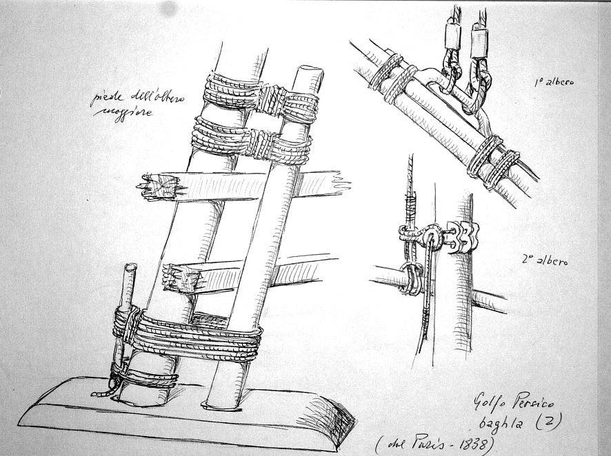
Usually the capstan (spil) was set up in front of the mainmast and then in that case it could be set up on the axis of the ship. In this way he could hoist the lower beam of the mainmast (the line then went along the foot of the mainmast via a bitt placed diagonally behind the mast). The lower beam of the jib mast could also be lifted from the capstan (also via a bitt, but behind the foot of the jib mast). And the anchors could also be retrieved by the capstan. A capstan was the only very strong power source on a ship and was used for everything (hoisting cannons, sloops, cargo) and was on large ships indispensable. Small ships used a windlass. Constant
-
The head seams of the planks should probably end on the underlying beams. Otherwise you can't nail it down. I wouldn't place the capstan exactly in the middle. If, for example, the anchor also has to be raised with it, it is useful if the rope runs along the mast foot without touching it. Constant
-
Siggi, Very nicely made! This shows real craftsmanship. Not only in the way of building but also in the research to the right details. You don't make the blocks as you find them in a model shop, but rely on the remains that have been found on the actual ship. Congratulations! Constant (Tartane)
-
Hi Jan, All my life I have been building models of historic buildings in addition to ship models. These are all commissions from museums in the Netherlands. Sometimes also from government agencies. There are currently 34. I have been building them since my childhood when I already had a great interest in castles. Recently I built a large model of the city of Zutphen, my hometown, which indicates what the city looked like in 1485. It required an in-depth investigation that I carried out together with an archaeologist and a building historian. I am also a building historian. Before that time, we already knew a lot about the city through the many studies we have done here in the city over more than 30 years. If the three of us agreed on what a certain house should look like, I built that house on a scale of 1 : 500. And that happened about 1400 times. In total, it took me five years in more than 6500 hours. It was determined in advance where the model should be placed. Especially for that purpose, a Medieval gun tower from 1557 was restored and a steel floor was made in it where the model could stand exactly. That place remains the definitive city place. That tower is further furnished as a small museum and is open to the public free of charge. In that tower there is also a cannon from that time that I built especially for that purpose on a scale of 1 : 1. I have already published the description of that construction on this forum some time ago. The last commission came from the National Museum of Antiquities in Leiden. For a permanent exhibition, they needed a model of a prehistoric Tell, as found in Syria, and which are about 6000 years old. On my website there are a number of models and ship models, but I need to update that website. www.constantwillems.nl Attached photo's of the model of Zutphen. A one-hour documentary has been made about its construction. It has already been on television a few times and that documentary has recently won awards in documentary festivals all over the world (San francisco, Milaan, Oslo, Oxfort). The latter was the first prize at the famous Cannes festival. An Constant

.thumb.JPG.7c7a988f29074d40b4753faf7521e8fb.JPG)
-
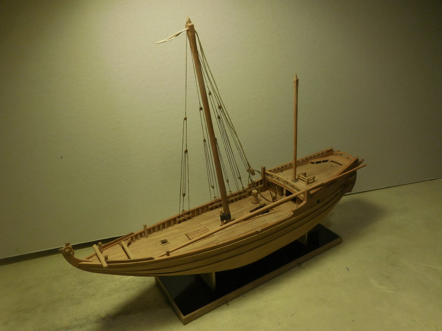
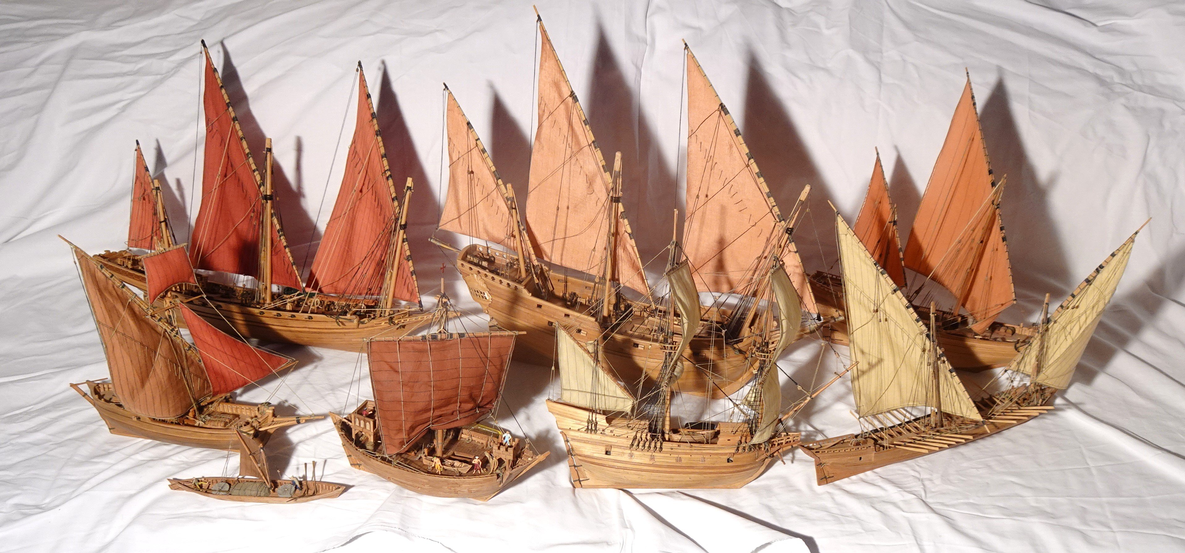
Hi Jacques The model of the Ghanjah is 32 cm long and 34 cm high. I built all my models on a scale of 1:87. It is the scale of the model trains ( H0 ). On that scale there are figures for sale that I always compare with the model to keep an eye on the human measurements. In the photo a part of the historic ship models that I have built so far. The Ghanjah is at the top right. Constant www.constantwillems.nl

-
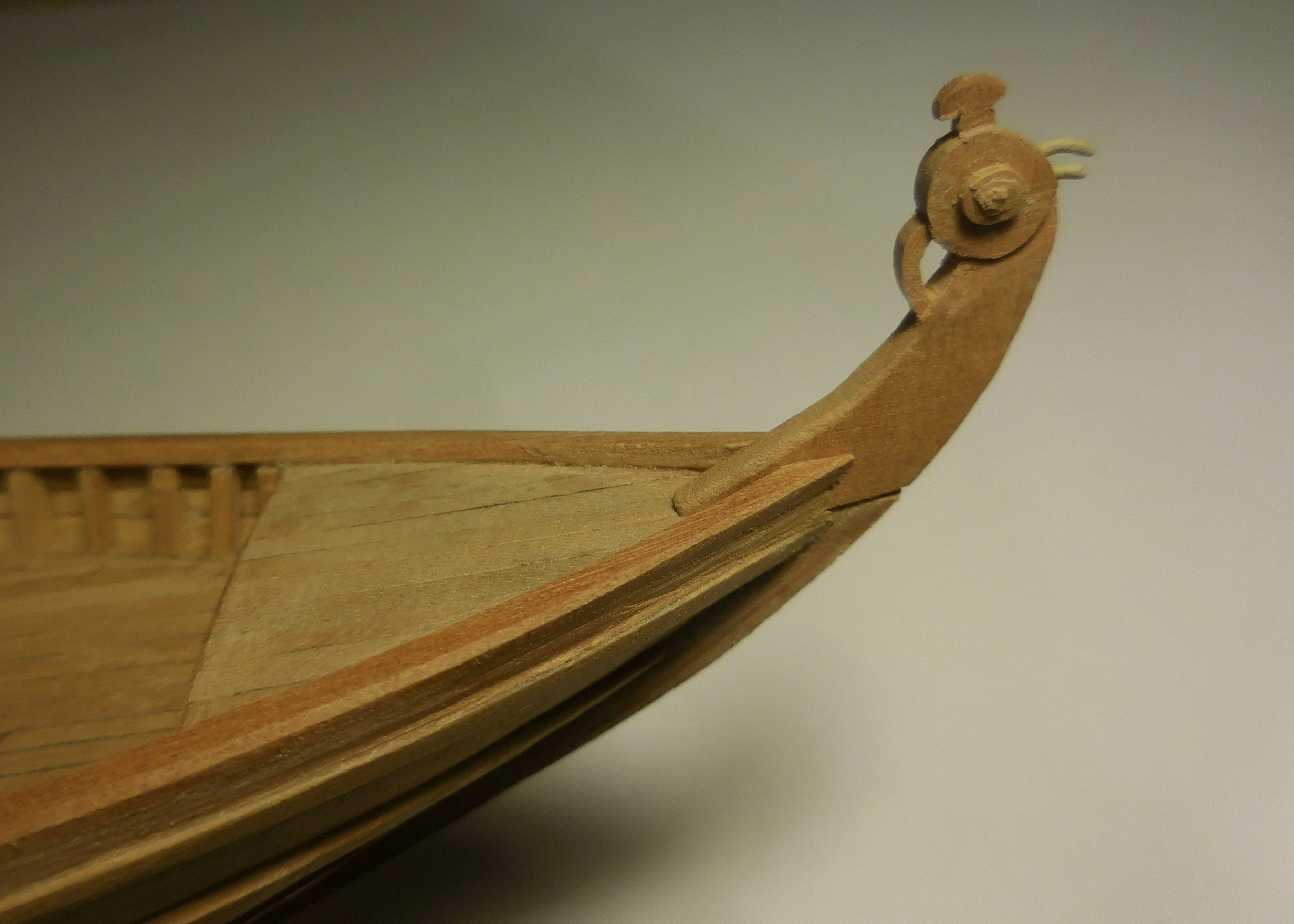
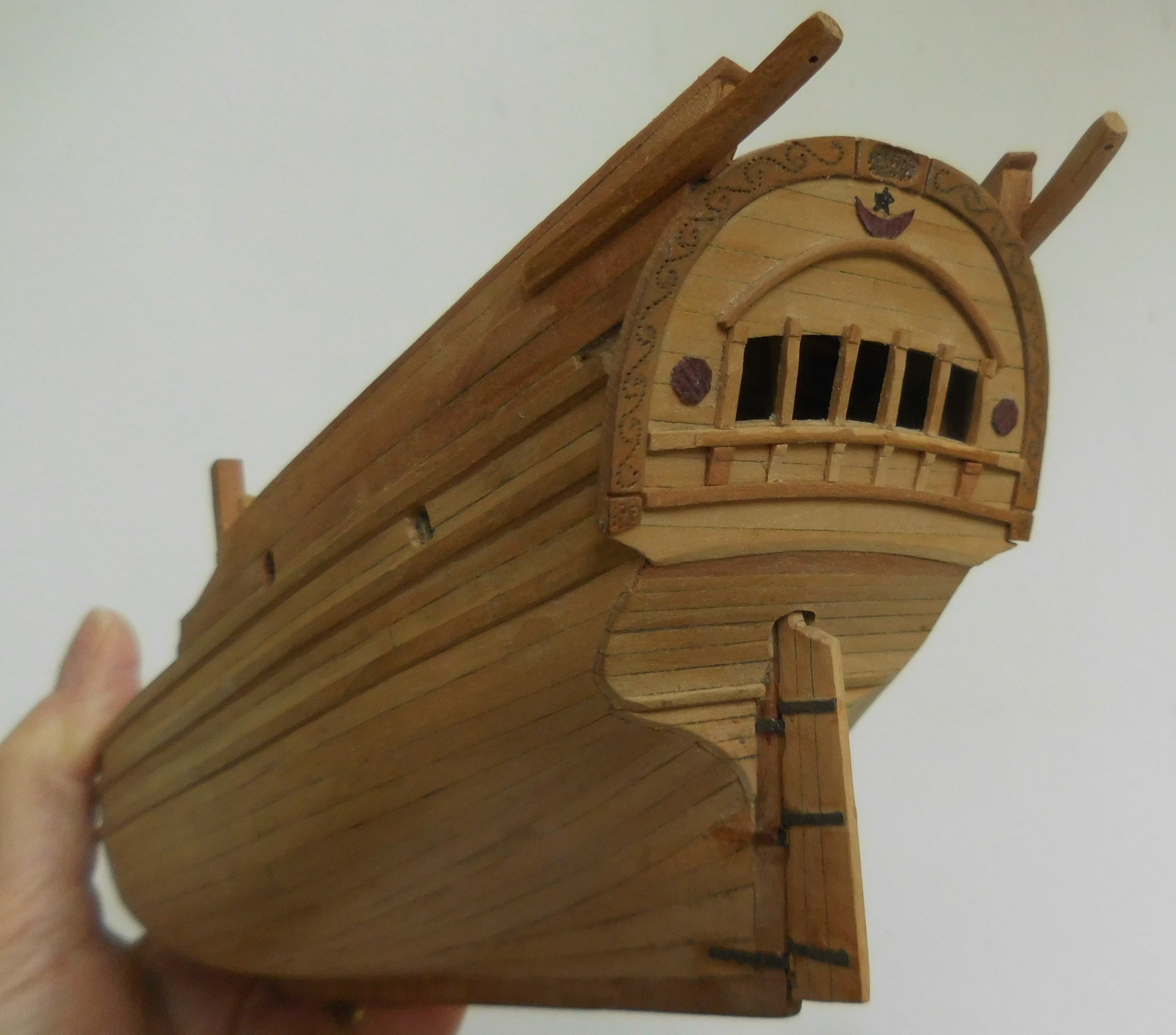
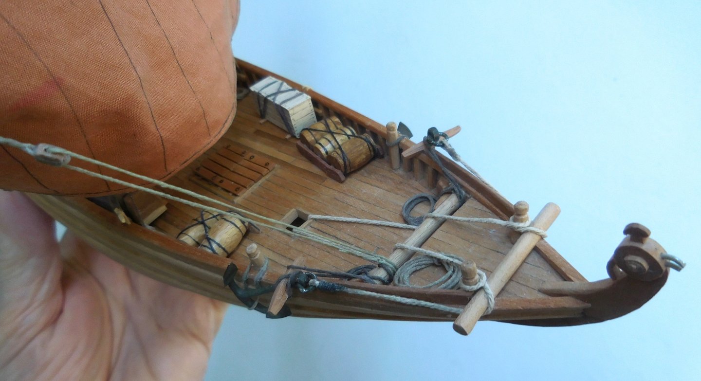
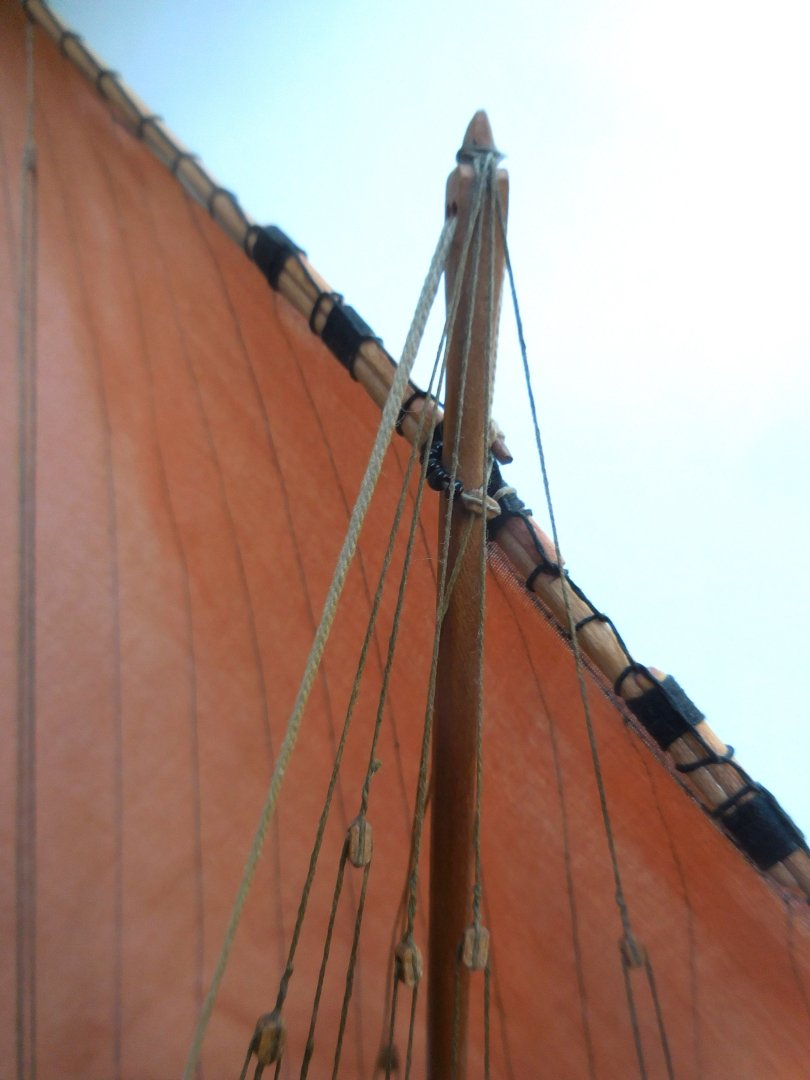
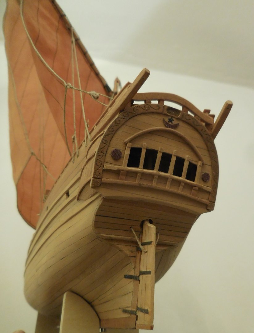
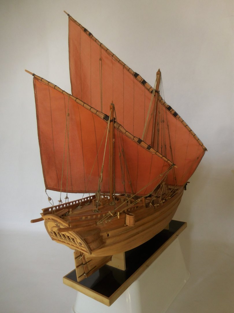
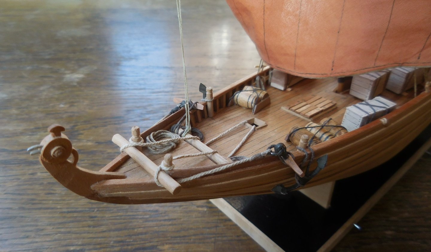
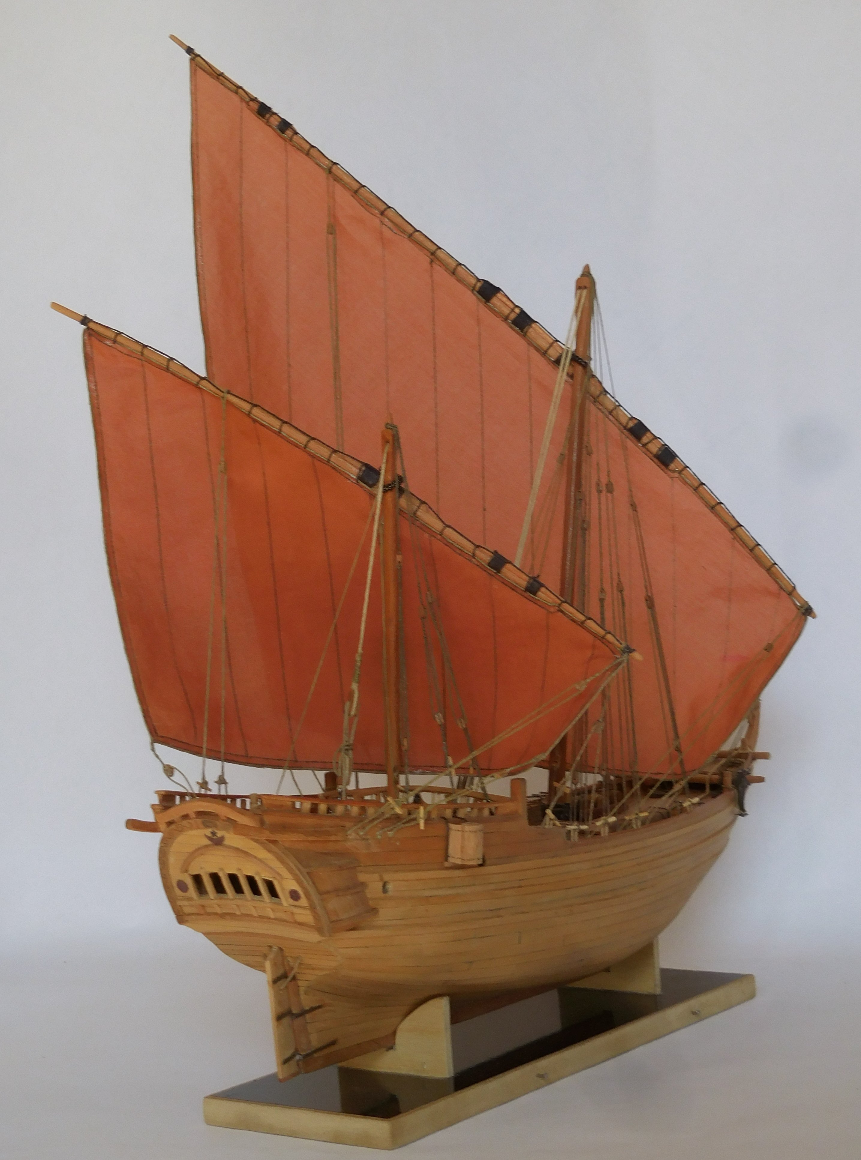
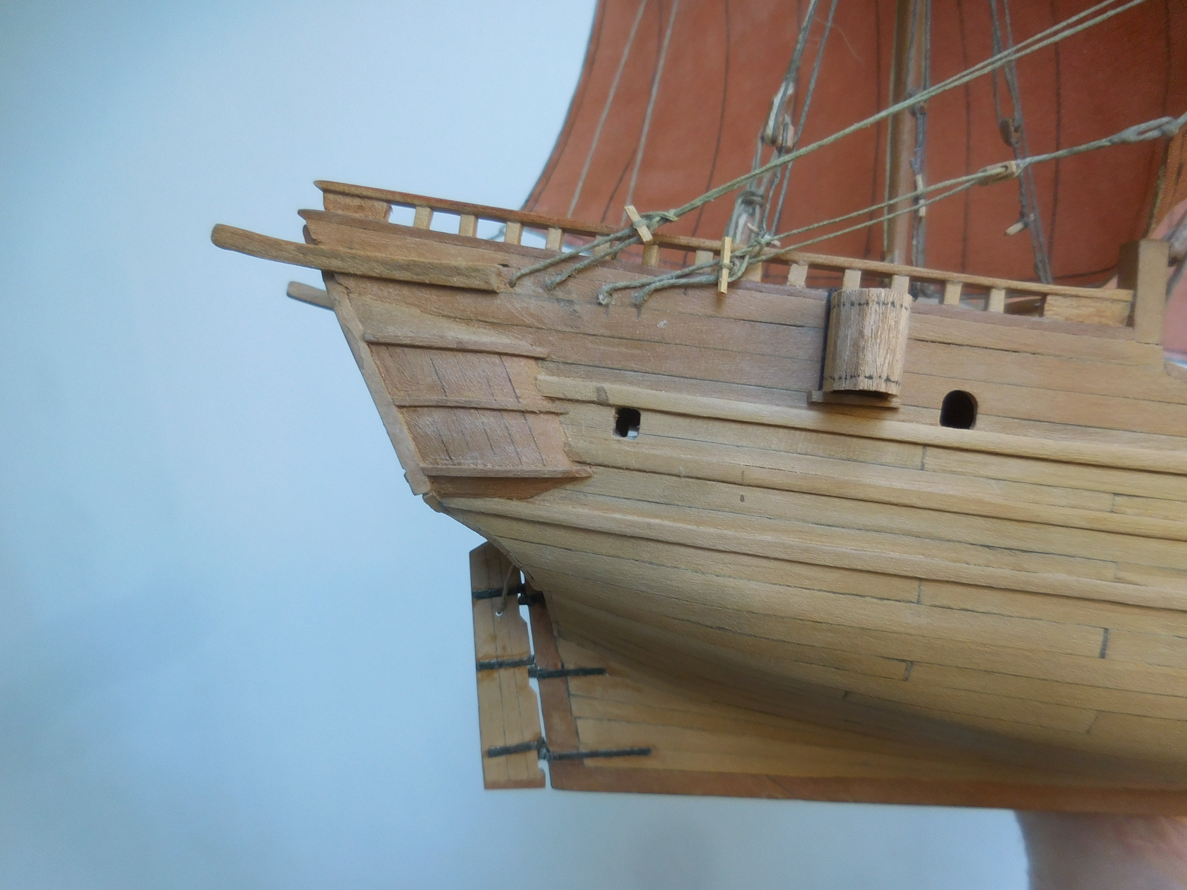
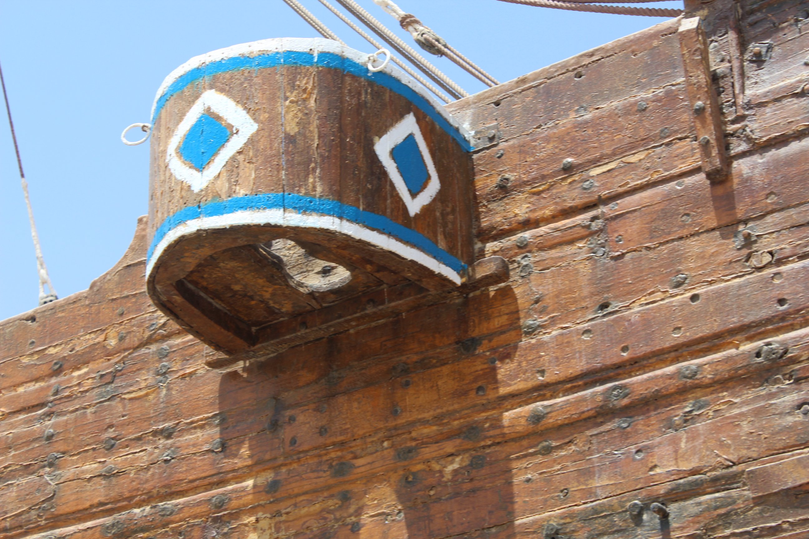
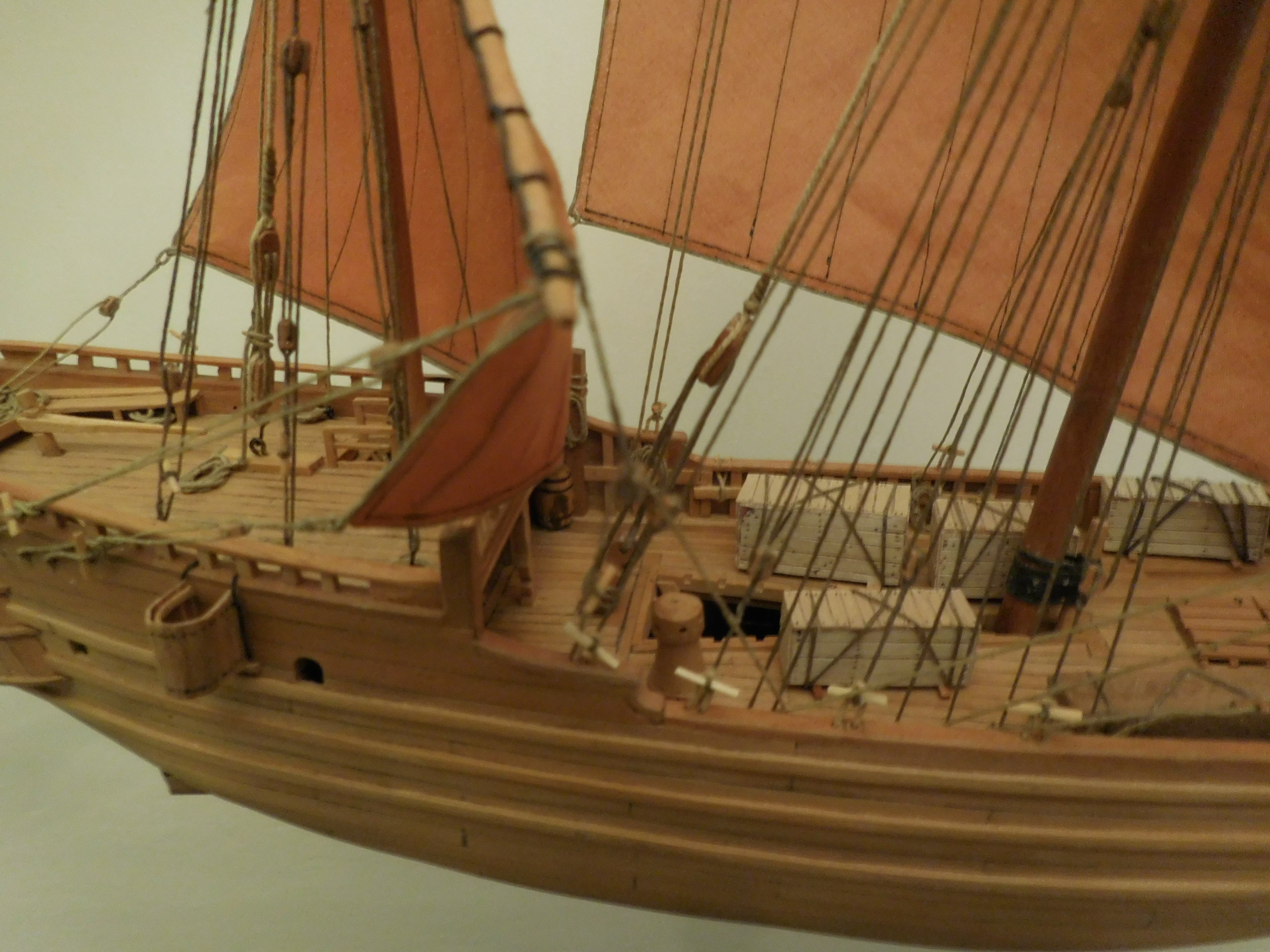
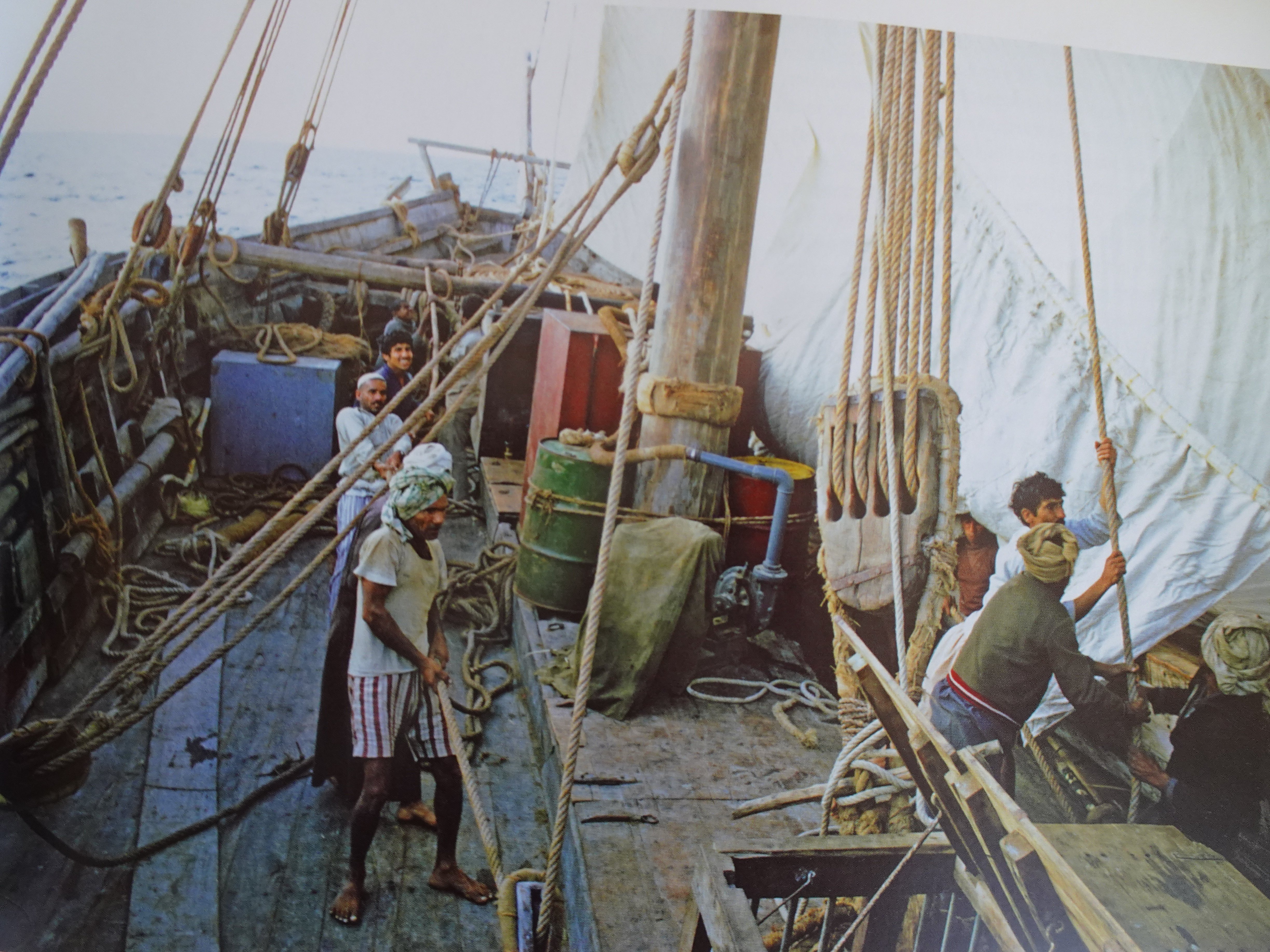
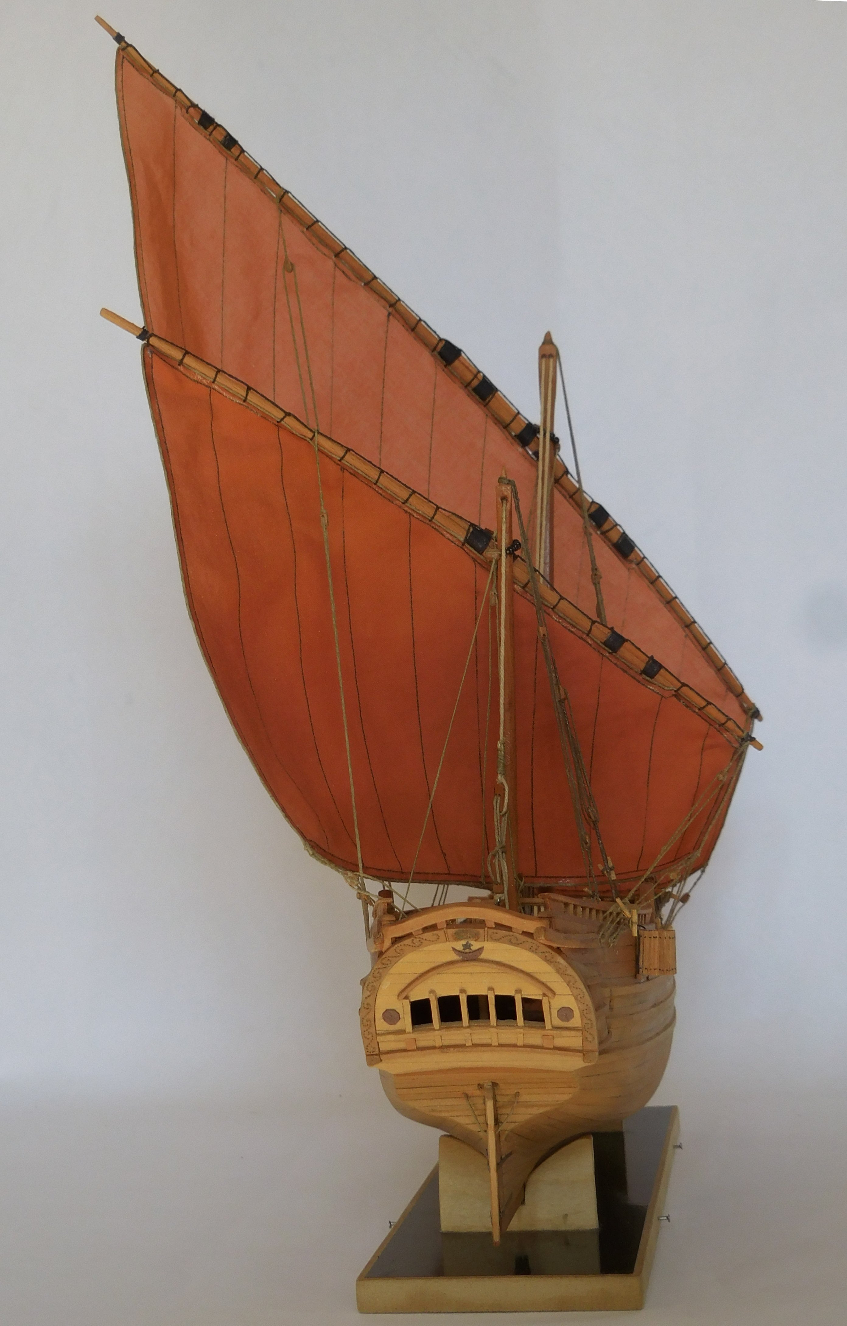
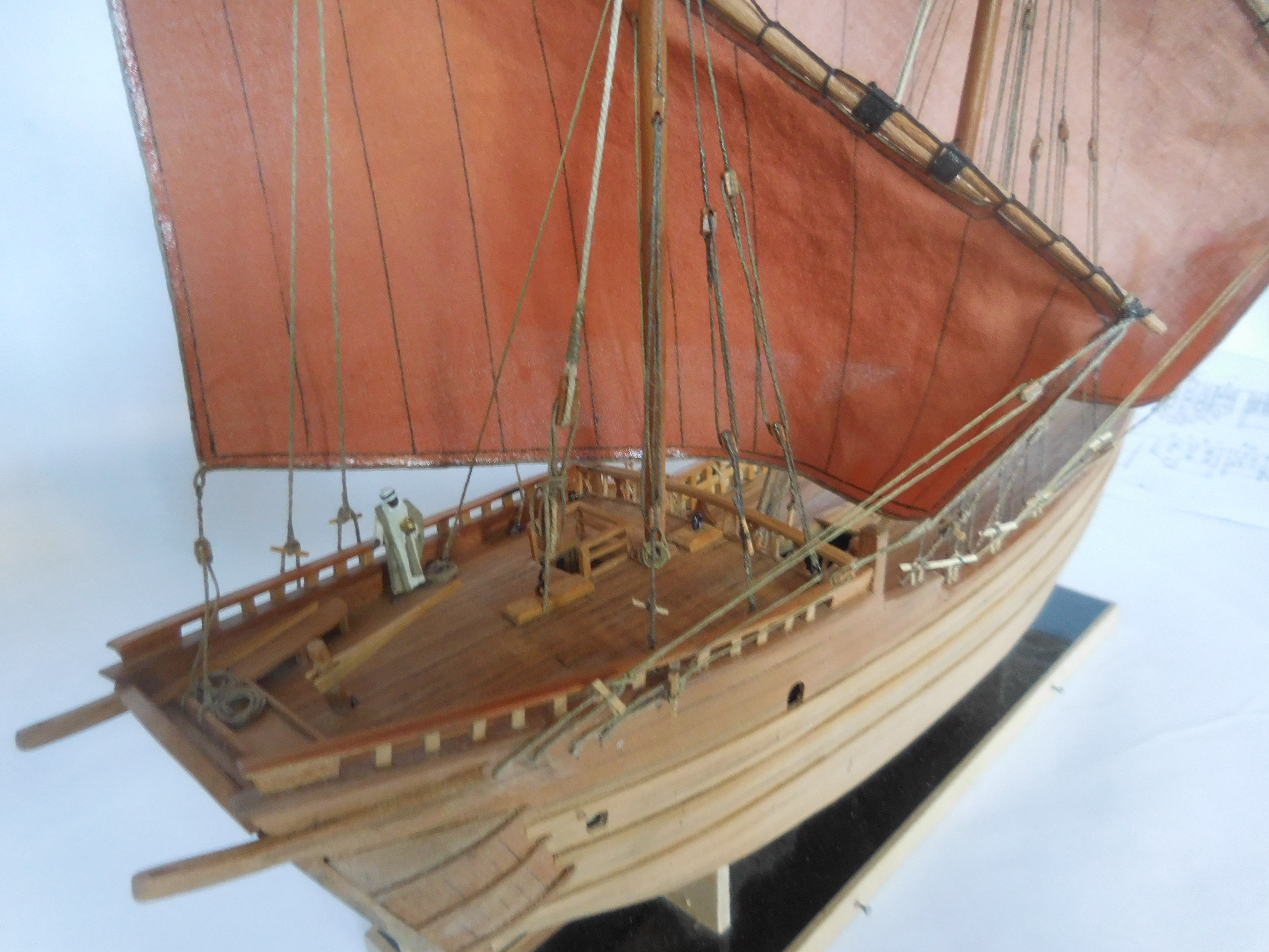
9 The Ghanjah is now completely finished, but there are always small things that I would like to add/change when further studying this beautiful ship from the Dhow family. The stern with a "Zuli" on the edge, a squat toilet made in a kind of half barrel. Every Dhow has this as standard equipment, sometimes there are two on each side. The thing is suspended from two ropes and could hang anywhere on the ship if desired. This also made it suitable as a location for carrying out maintenance on the outside of the ship. Part of the cargo on the deck. To the left below the capstan, mainly intended for raising the anchor and as a source of power for lowering and erecting the mast. There are few photos of Ghanjah's that give an idea of the decks during the operation of those vessels. However, it is clear that, in our eyes, it was chaos. Things were lying and standing everywhere and often the deck planks were hardly visible. The laying of the ropes required for the running and standing rigging was apparently also left entirely to chance. Wherever there was an opportunity, they tied things up. For example, I saw a photo where the sheet of the mainsail was tied to the bench of a sloop on the deck. Work on hoisting the yard on deck of a Boum. This type is much smaller than a Ghanjah and apparently there was enough muscle power to do without a capstan. The four discs in the halyard block are there for a clear reason. The foreship. Just behind the bow a wide beam with two upright bollards. Standard with every Dhow. Behind it is a second beam (over which the anchor ropes go), which is intended as a support point for lowering and erecting the mast. The beam is completely fixed and therefore cannot rotate. The figurehead is a stylized head of a rooster. characteristic of the type of the Ghanjah. The two sister ships of this ship, the Kotia and the Baghla, have different figureheads. The top of the main mast with the attachment points of the mittens which in this case are only on the starboard side. In July 2017 I started construction, but I didn't work on it continuously. On the one hand because the research into this ship took quite some time, on the other hand because I also had other activities. I made all parts up to and including the anchors myself. I didn't use any plastic in it. I never paint my models, it's mainly about the construction It was a wonderfull experience to work on it. Constant


-
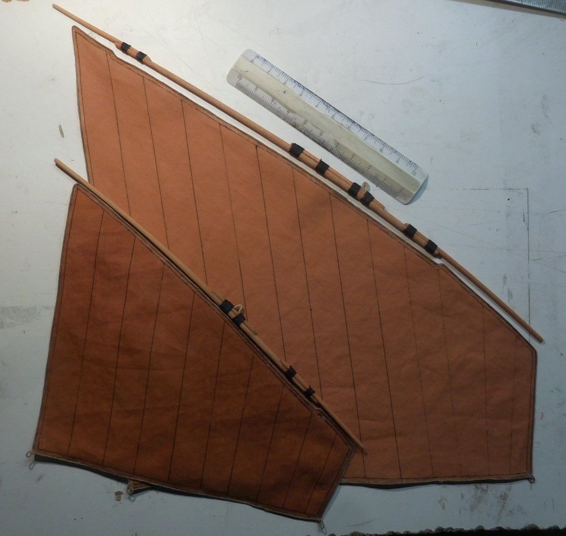
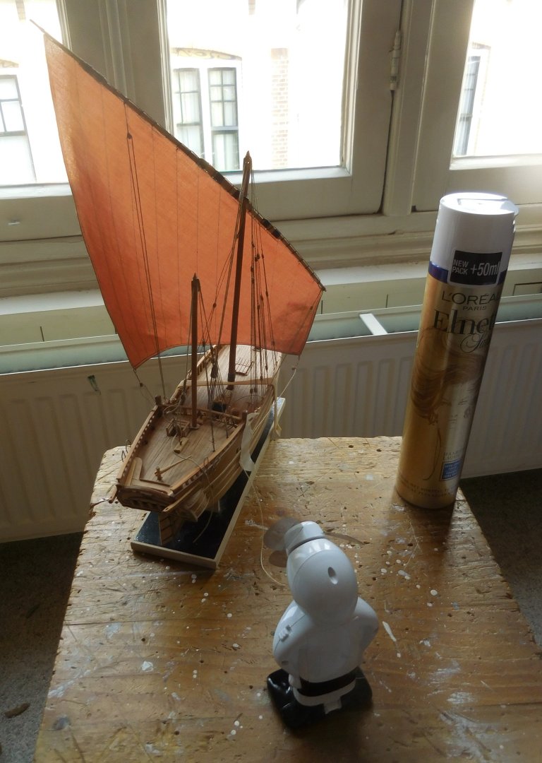
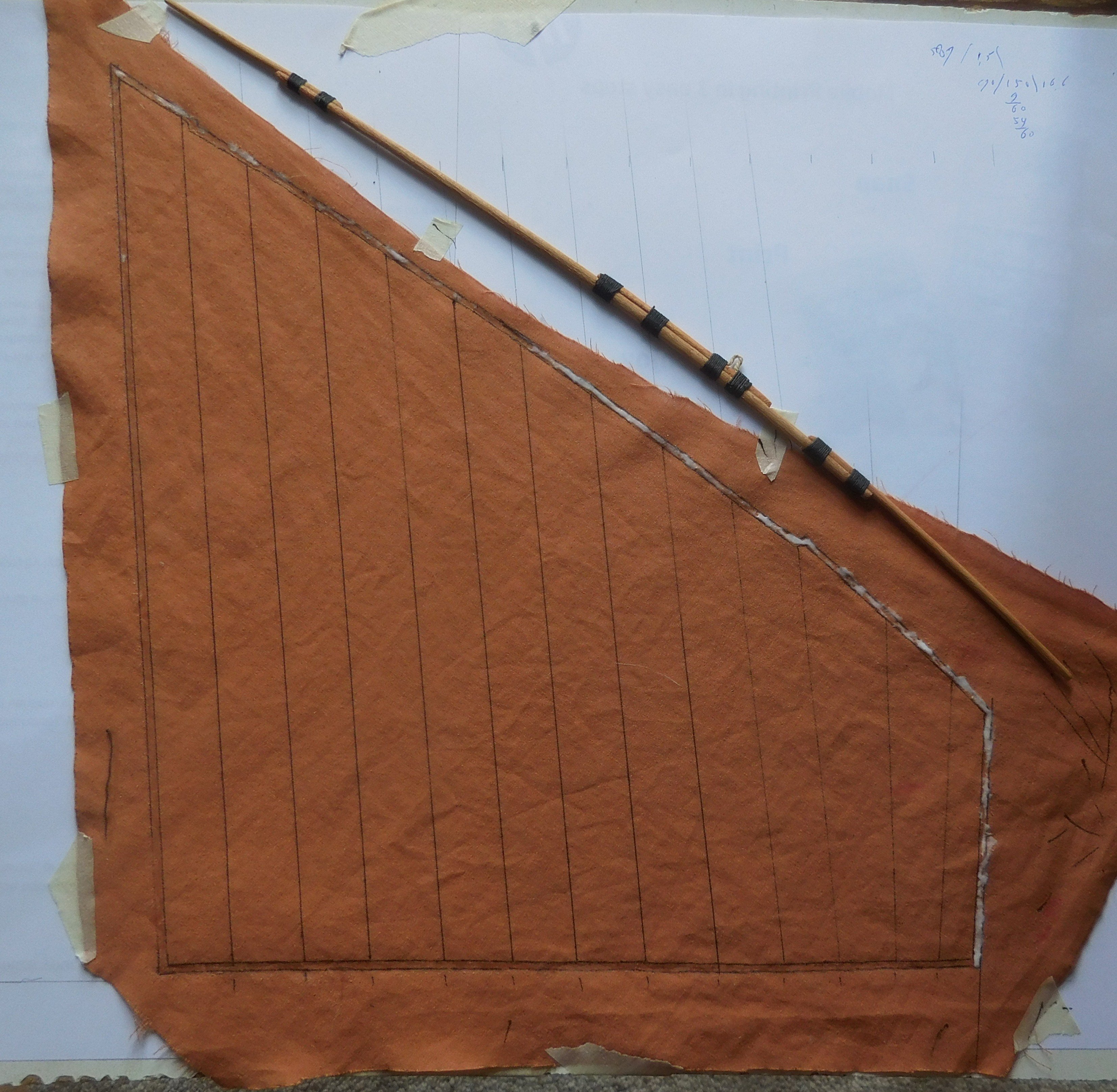
8 A difficulty arose in making the sails. The only store in my city that sold the right kind of cotton for the sails, I am very critical about that, no longer had the material in its range. I tried it at a thrift store and found myself among a large collection of cute women's blouses. And yes, there was one that was made of 100% cotton and in the right thickness and fineness. For 1.5 euros I bought it and explained it to surprised ladies who were also looking there, but for a completely different reason, for which I needed it. I made the sails completely according to the procedure I explained on my website; www.constantwillems.nl Just before that I had slightly bent the yards by securing them in the shape on a board. Then I steamed the yards through the steam from our cappuccino machine, and let it sit for two days. Now they look fine. Making the main sail. After the fabric was colored in a paint bath and dried, I carefully stretched it on a piece of plasticized plywood. On top of that a piece of paper was fastened on which the entire sail was drawn. Apparently there will be no doubling in the corners as usual with Dutch sails and there is also no reefing band. The sails were not reefed. In heavy weather, a smaller sail was simply raised. I smeared the leech on the edge of the sail with very slightly diluted wood glue. As little as possible so that the glue does not shine after drying. I rubbed it all around and worked clockwise. As you can see here, about half of them have already dried completely and are not shiny. After this I cut out the sail and attached the bolt rope against the edge all around. Small loops are then placed in the corners. That attachment was again done with wood glue. Above the sail I have placed the yard which I have bent slightly. It looks a bit strange if it can be seen dead straight on the model. I can recommend this method to everyone. Especially if you build on such a small scale as HO (1 : 87). It all stays firmly in place and because of the glue edge it does not fray and that edge is already pre-glued when attaching the leech rope. The sails ready to attach to the yards First I rigged the model with only the main sail. Because the sail hangs down a bit limply, I decided to keep it in shape. A small hand fan was placed behind the ship (the kind of thing you need on hot summer days if you are a tourist). I let it blow and positioned it until the natural bulge of the sail was created. Then I carefully sprayed a number of clouds on the tarp with hairspray from a distance of about 30 cm (instructions). After spraying about five times, I turned off the fan and the shape remained in the requested shape. I drew on the tarp with a black ballpoint pen. That didn't flow out because of the hairspray. And it smells good in the house for the time being. In any case, it is advisable to make a test first to try out how much you have to spray on the cotton to get it stiff and whether the ink you used to draw on the sail does not flow out. By the way, instead of such a small fan, you can also use a hair dryer (to immitate a storm?) Then the mizzen was applied and the above process was repeated. There was a question whether this will last long. I did this treatment in 2018 and now it's 2025 and the sails still feel stiff and stay in shape. So I am confident that it is long-term. Mizzen is now ready. And also treated with lacquer. There are still a number of things to be put on, the anchors, the outboard toilet, the deck cargo and a lot of coiled ropes. Constant


-
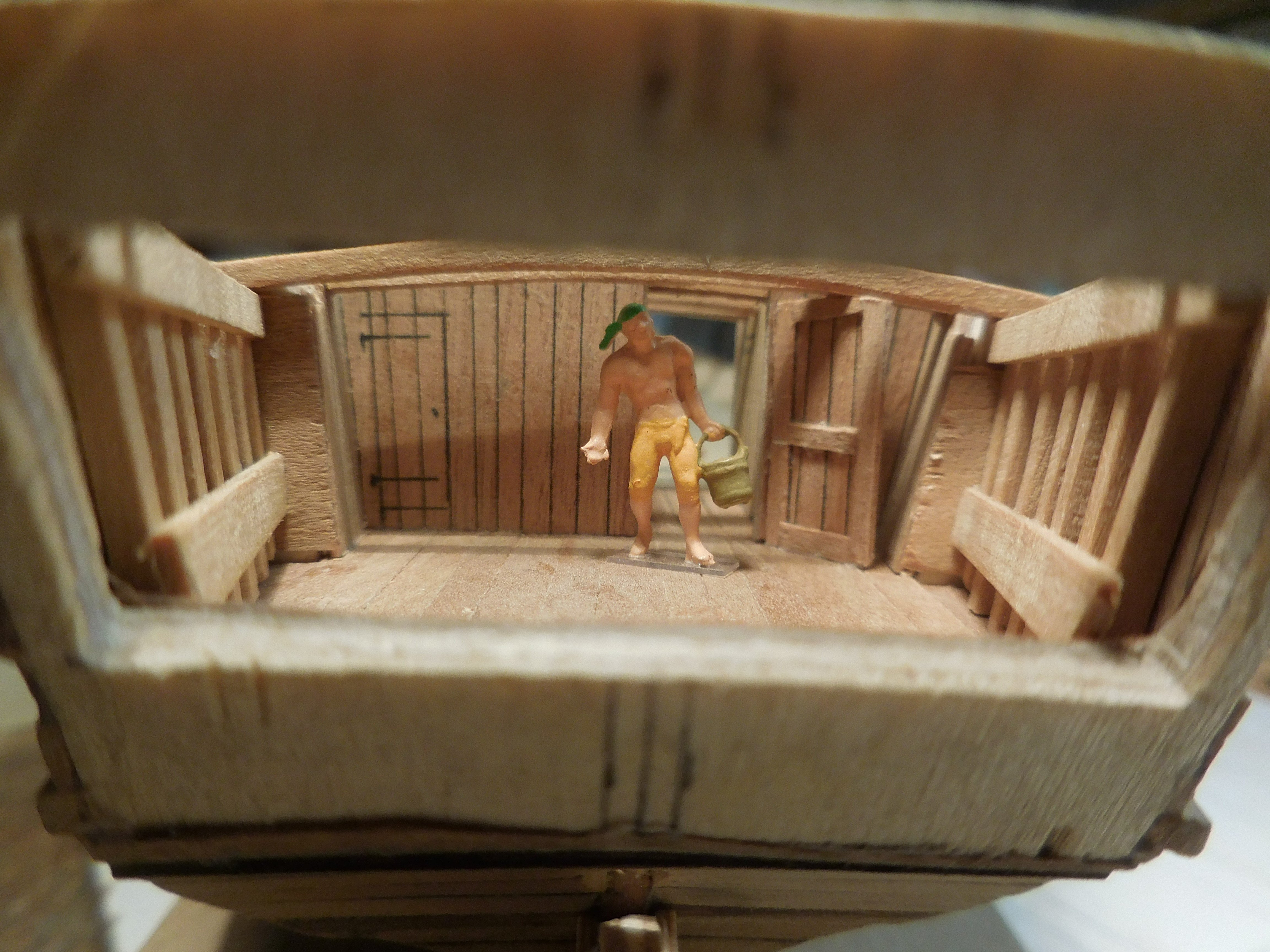
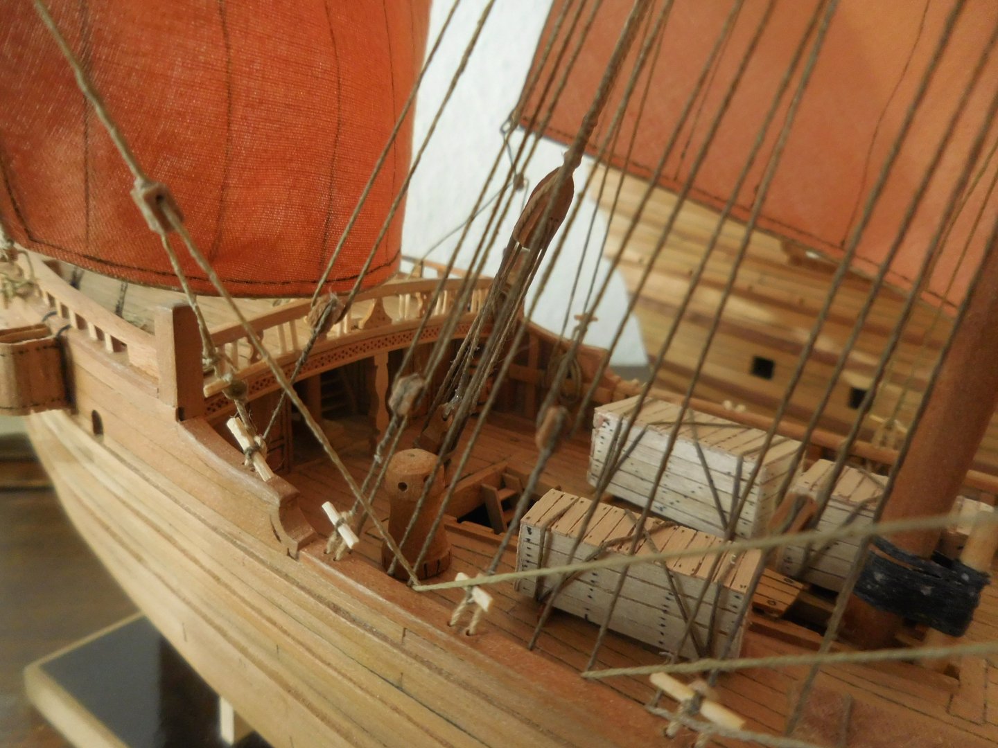
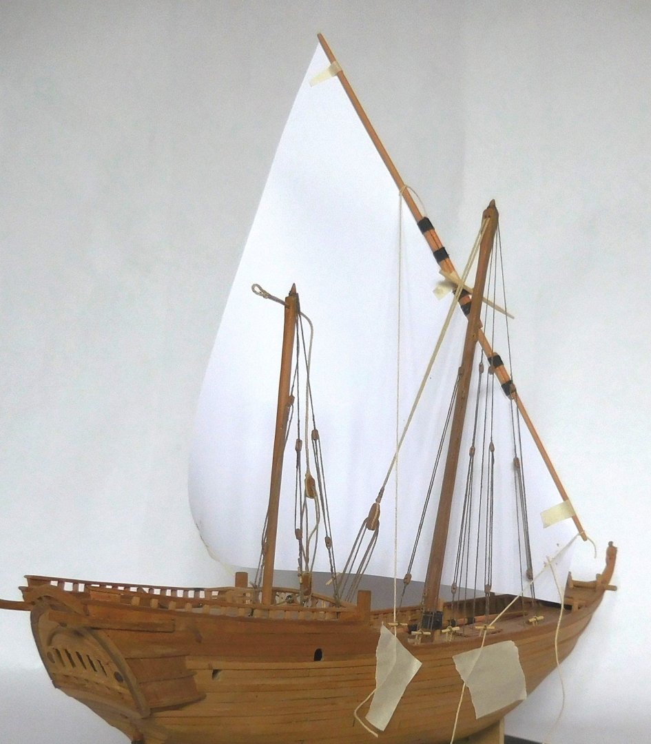
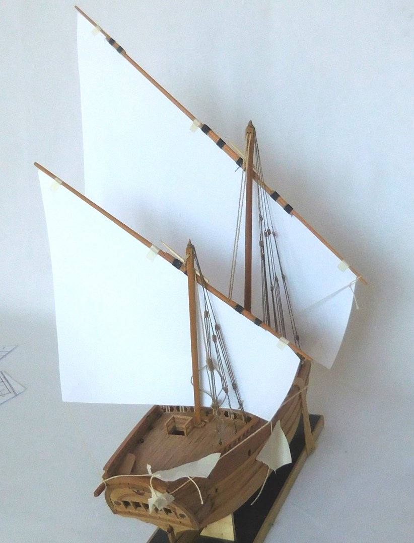
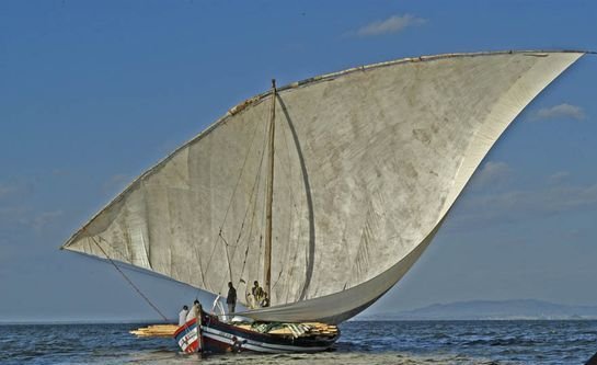
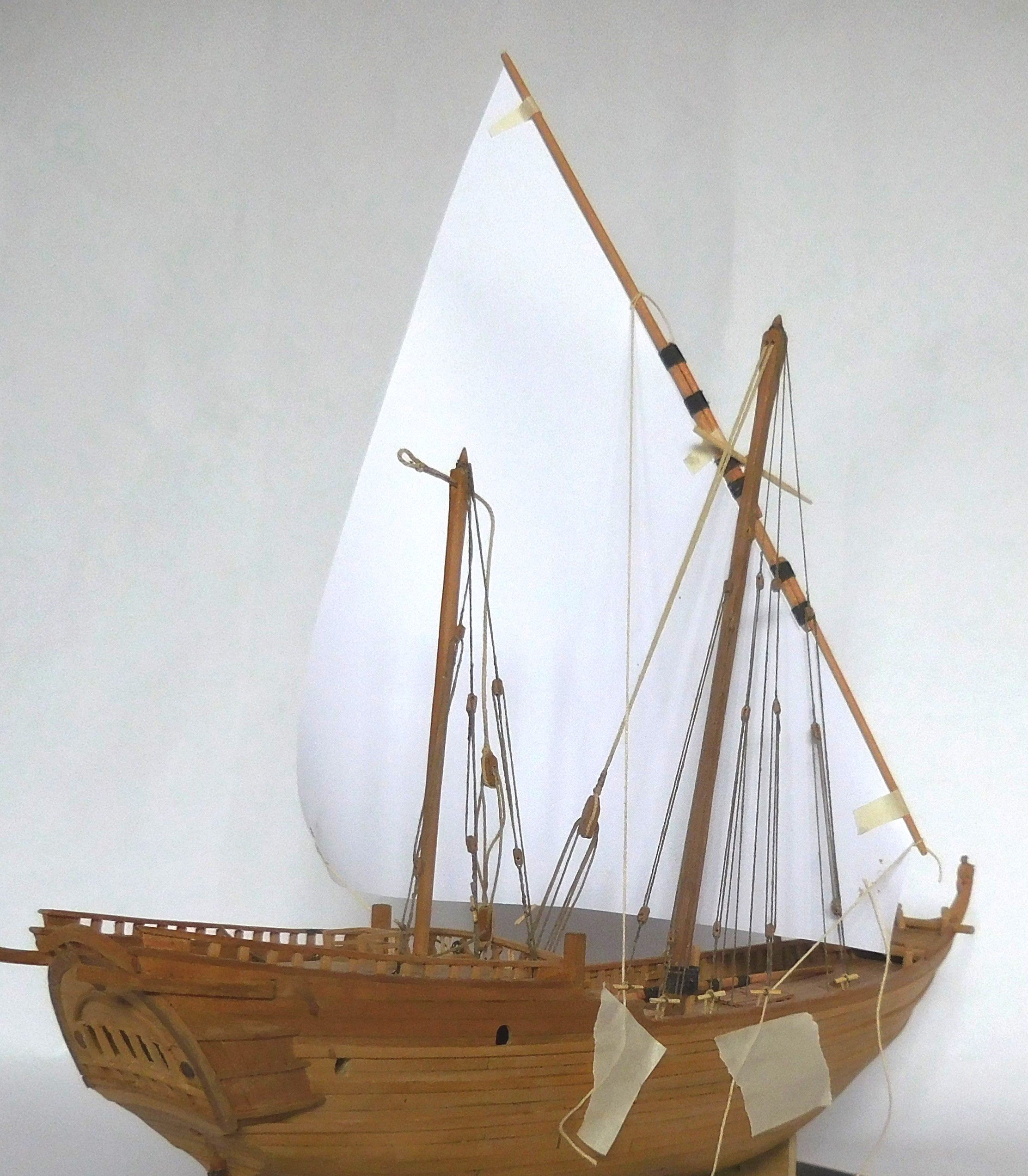
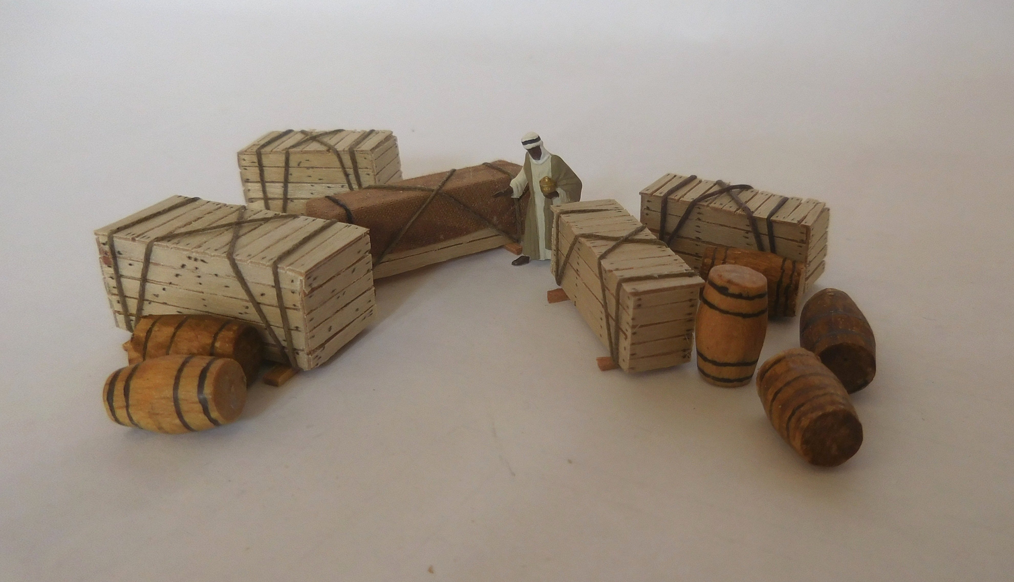
7 For the design of the sails I used provisional sails made of paper The yards were already finished. To get the color of the wood of the yards in line with the rest of the ship, I made it from pear wood. When they were done, an unexpected movement broke the yard. Pear wood was therefore a bit too soft. I started again with beech wood which is much stronger in the longitudinal direction. To glue the parts together I colored it with brown watercolor. After a lot of cutting, pasting and trying again, this became the result for the sails. I found not really good drawings for the sails. I obtained this form after studying everything I could get my hands on in terms of photographic material about sailing Ghanjah's. It all looks a bit static because it is stiff paper. The yard of the mainmast is almost as long as the ship, which is normal with those ships. The mizzen yard is slightly shorter. I also have to bend the yard a bit. The yard is here over the deck. How enormously long such a yard can be is shown in this photo, which makes you wonder why that thing doesn't break. I don't think Dutch shipbuilders would dare to do this. As this photo shows, a yard sometimes looks like a collection of various pieces of round wood. The piece on the left is tied to the bottom with a rope and has nothing to do with the yard but probably serves to hang a kind of awning over it. The mizzen yard is shorter and the extension at one of the ends is not necessary. What I have understood so far is this is teak, just like the hull. Such ships often carried a considerable amount of cargo on deck. When the model is completely rigged, I will look for a place for these crates and barrels. Until then, I kindly asked that Arab to watch the load. Constant


-
Hi Lecrenb Thank you for the compliments on the rigging. Before I start building a ship model, always skratch, I do a lot of research on the rigging and technical specifics on the model I want to build. Such an investigation can take months. As a result, I learned a lot about the different types of ships. I really want everything to be right and for the model to look just like the ship in full size. It is logical that I do not always succeed, not all details can be traced. But I see that not every modeller strives for that. Most builders who purchase a kit simply rely on the descriptions and drawings that indicate how the model should be. There is nothing wrong with that, in the end it is all about the pleasure of building and if the result looks nice then that is also good and a builder can rightly be very satisfied. But often I see many models that are not correct, and I mean especially models of sailing ships. It also seems strange that it is simply assumed that what is in a museum is always correct. For example, it is thanks to the three models of chebecs in the maritime museum in Paris that there are kits from all kinds of manufacturers on the market that are incorrect. Those models in Paris were made after the chebecs had completely disappeared. So they are fantasy models that are made from traditions and incorrect information. It is easy to determine what is not properly represented there. A few years ago I built a chebec myself. The correct details were created with the help of many old images, descriptions and drawings that were made before the chebec disappeared in the early 19th century. That data is very reliable and logical. They came from people who had sailed on those ships themselves, and from scientists who took the trouble to accurately measure and draw those ships. Subsequently, that data was published. After the chebecs disappeared, many inaccuracies appeared. Suddenly there was a sloop on the deck of the chebec. It is demonstrably incorrect that there was no room for a sloop at all. You don't see that at all on original images and measurements. And so there were more details. That's why I like to explain those technical things in my descriptions of the construction process. According to other builders, and also in reality, I will sometimes be wrong of course, but then I like to hear about it and I will always be happy to discuss it on a pleasant way. Constant
-
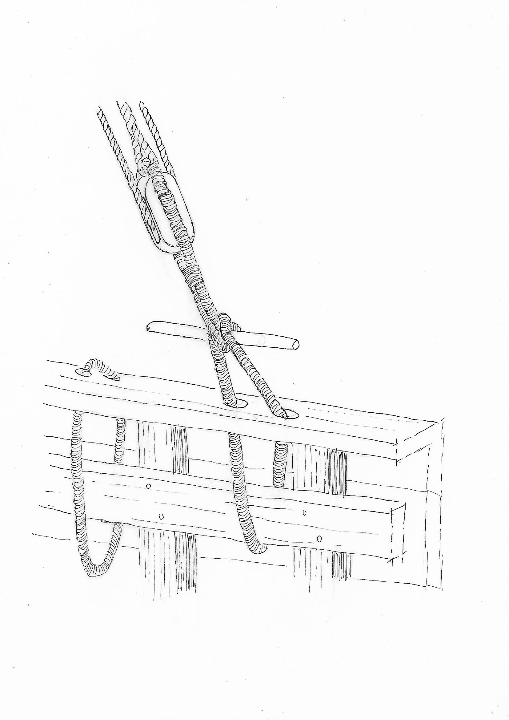
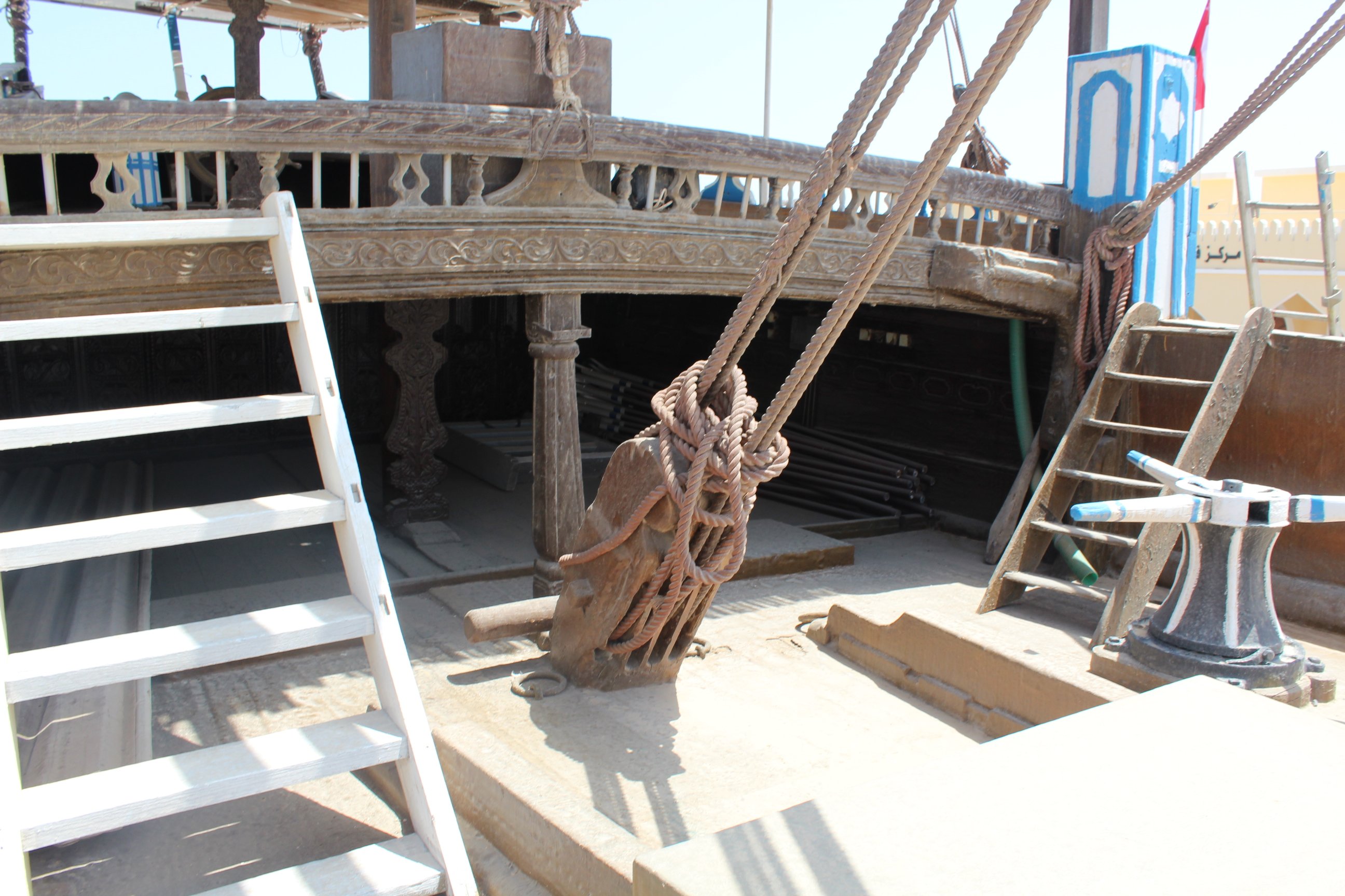
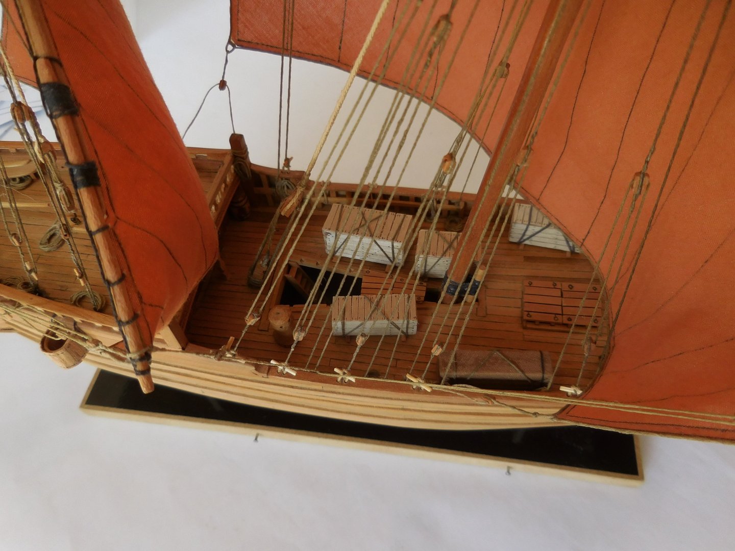
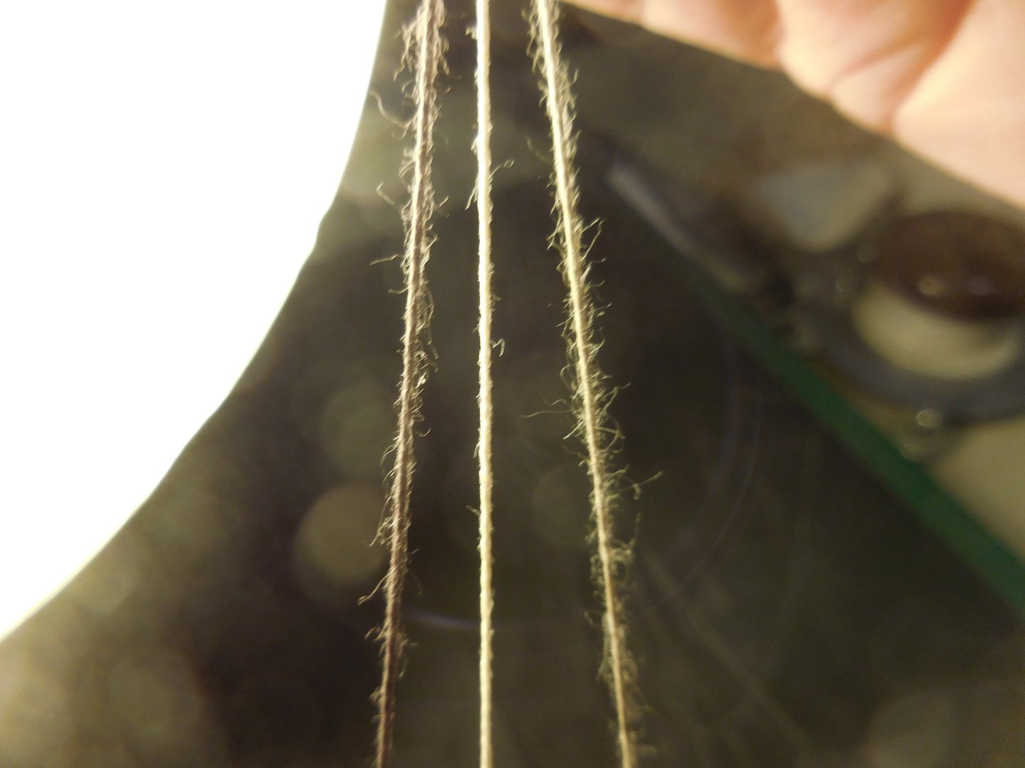
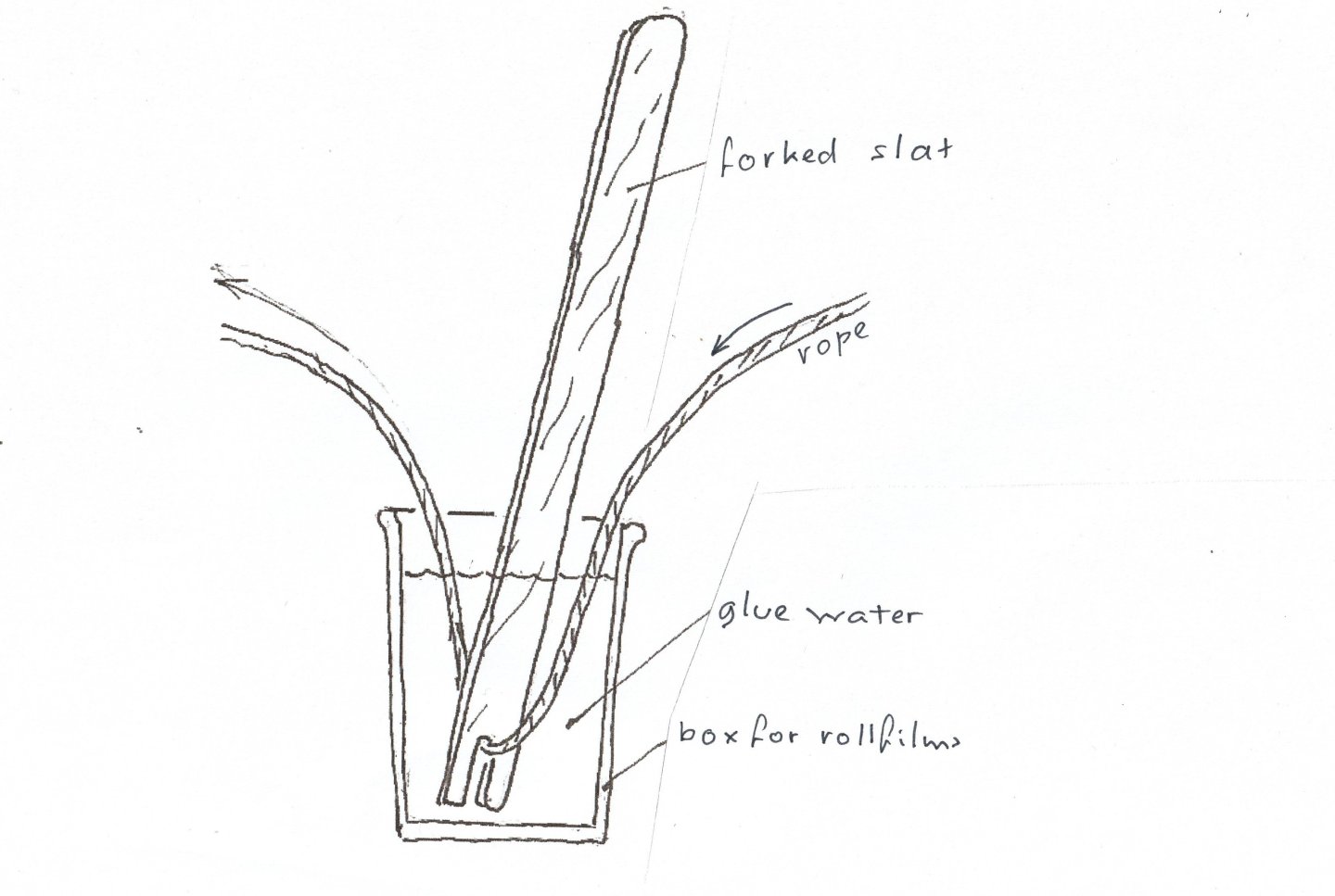
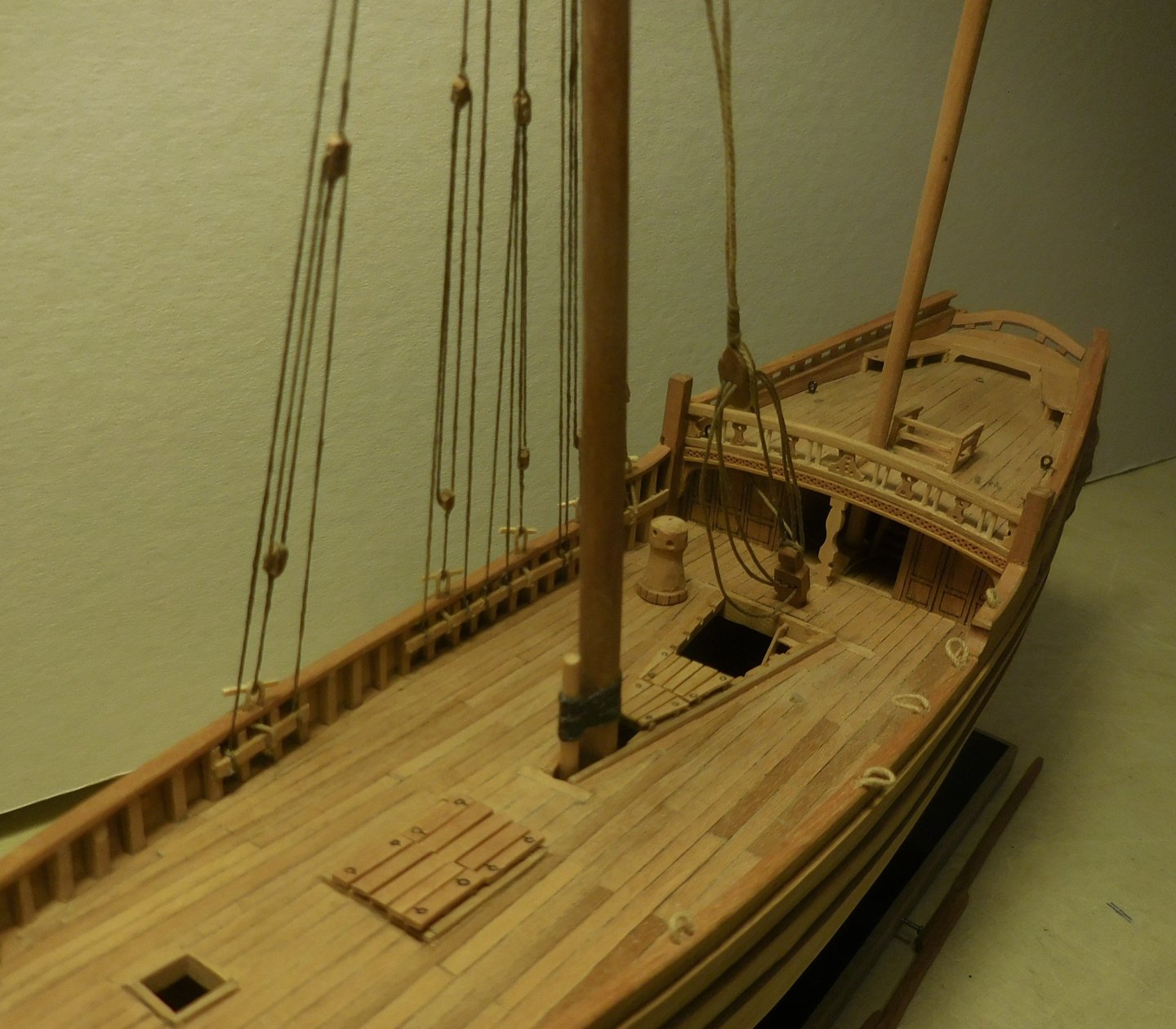
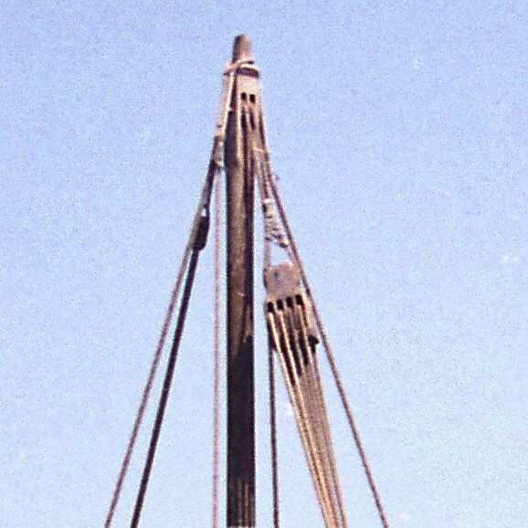
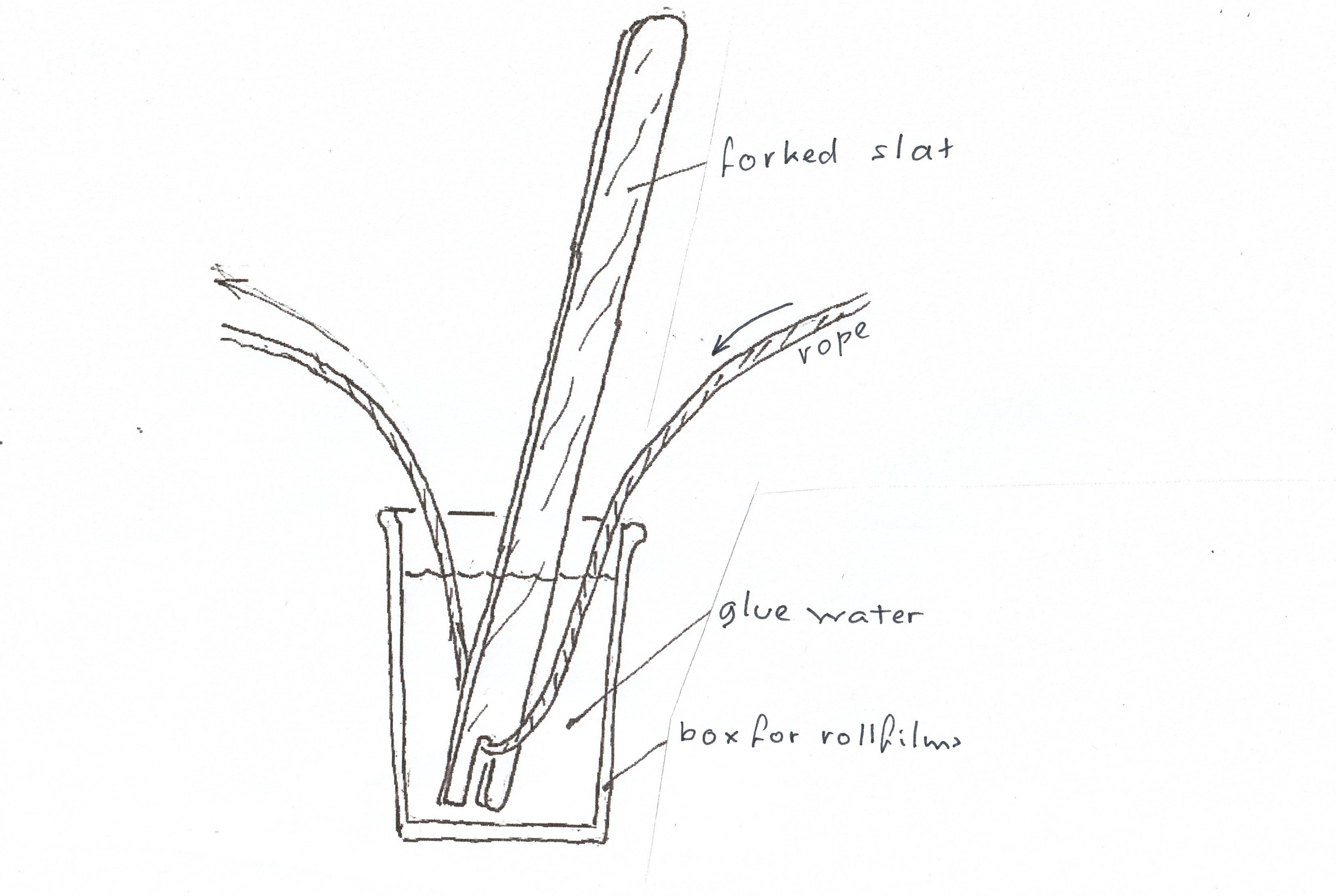
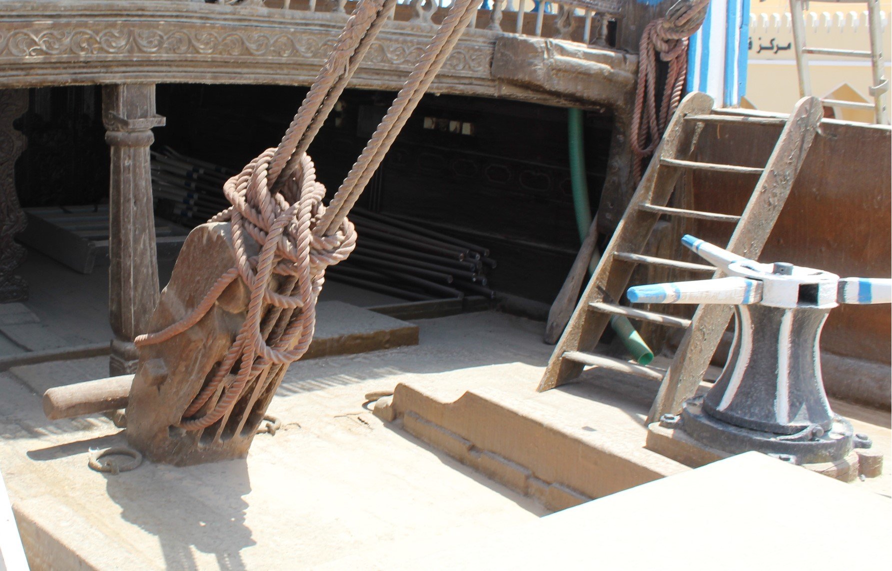
6 I make the blocks myself from pear wood. The method is as has been described several times before. The necessary rope does not come from the model shop, but I make it myself. Because of the small scale, it is not feasible to maintain exactly the thicknesses that you do follow with models on a much larger scale. I actually limit myself to thin and very thin. As I described before on the forum, I use black and white thread that is on large spools (I think one kilometer long) with a thickness of 1.5 mm. And that can be bought in shops for fishing equipment. It consists of 12 strands. I cut off a piece of about 1.5 meters and that piece alone is more than enough for all the rigging of the Ghanjah. I sift it out until I have rope of 2 and 3 strands. For something thicker I use 4 strands. I wet this in glue water. About one-third glue, the rest water. I put a screw eye on a drill and tie the rope of 2 strands to it, for example, while it is still wet from the glue water. I tie the other end to a fixed point. Then I let the drill run until I like the result. You then have a twisted piece of rope that I then wet again and hang it up to dry. Be careful that it does not turn back on its own. After drying, you have a nice piece of cotton rope, without nylon, in a thickness of less than a mm. Because of the glue, it no longer turns back. The rope is made as described above The advantage is also that because of the glue water, no pieces of wire will be perpendicular to the rope. Something I find it very disturbing with wire that is available in the model store. Those ropes attract a lot of dust that gets stuck to those protrusions. If it also contains nylon, the rope is difficult to glue. The rope that I make in this way can be simply secured with wood glue without. Because the white rope is still very white, I take a little mud from the garden and rub the rope with it. This makes it a bit grubby, which imitates the many uses on a ship well. I use the "white" rope for the running rigging, the black one I use for the standing rigging. It will be clear that hardly any black rope is needed for the Ghanjah, in fact everything is running. Left and right rope from the model shop (Artesania Latina) and that contains nylon. In the middle the rope that I put together myself from pure cotton thread and treated with glue water. A second method I use for glue water. I provide an old box for film rolls with glue and water. Put the lid on and shake well. Then I slowly guide the rope through, held under water by a forked slat. Making the rigging on the windward side for the mainmast. There will be no shrouds on the port side, which is a bit of a strange sight now. I have already described the reason for this in episode 4. In this model, I assume that the wind comes from starboard. Windward side is starboard, leeward side is port. Furthermore, the deck hatches have now been installed and a ladder has been placed in the hold. The capstan is also present. This is placed eccentrically so that the anchor rope can also be guided along the mast. The shrouds are attached with sticks. The halyard block hangs a bit but that becomes much tighter after attaching the yard. The large mast is attached to a small pole in front of the mast. On the bulwark on the port side, the windward side, you can see the nooses that serve to attach the shrouds when the sail is fed over the other side of the mast The capstan and the bitt to which the hoist with the halyard block is attached on the ship in Sur. The small fixed pole on the ship to which the mast is attached by means of a seizing. Behind this is the higher hatch over the opening through which the mast can tilt backwards. This hatch is covered with a tarpaulin. Constant

.thumb.JPG.04a41b65f3ea375921049482e4b8d97d.JPG)
-
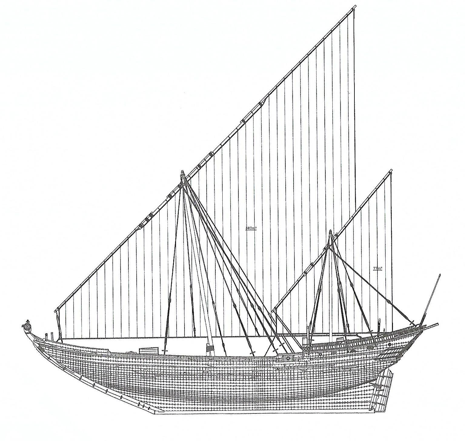
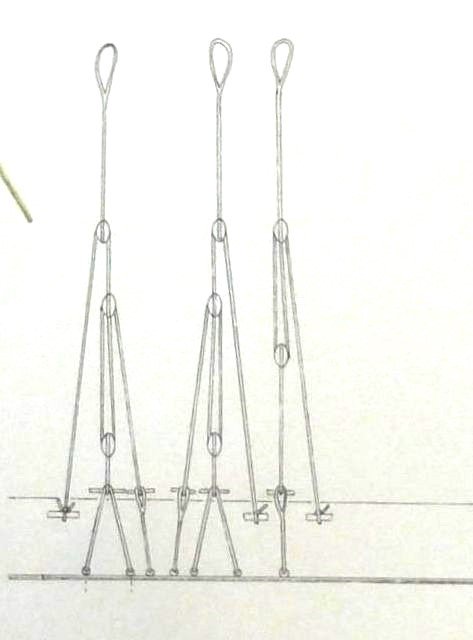
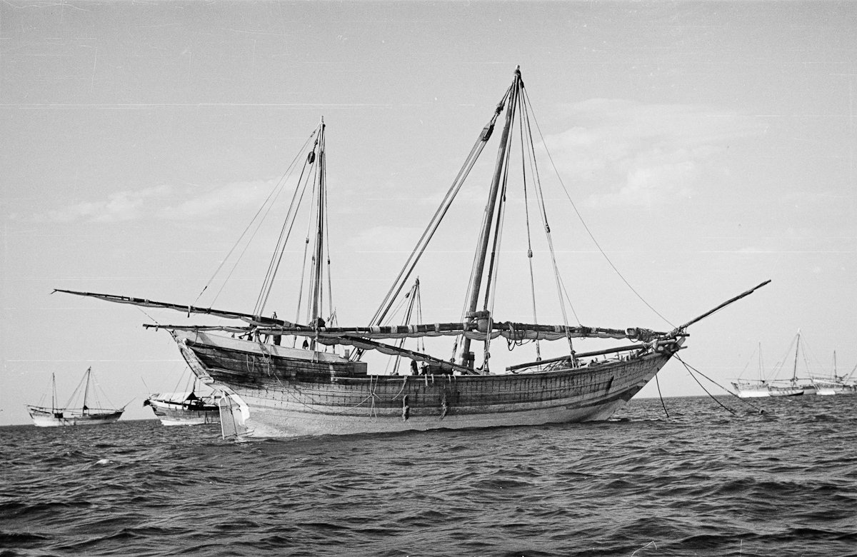
5 At the moment I am ready to focus on the rigging. What immediately stands out is the simplicity of this. It cannot be compared to a square-rigged ship. The absence of large pinrails seems strange. The sails could not be reefed, they simply took two or three sails that were used according to the weather conditions. Sometimes there are only two, but often only one leech line on the sail. See the first photo of this story, where only one is used. A photo of a sailing Dhow, in this case a small Boom, with one mast. Note the lack of the many ropes that are so common on square-rigged ships. Only shrouds on the windward side, no ratlines, no top, no stays, no deadeyes and lanyards. Only a heavy halyard block that is used to hoist the yard and hold it in place and a capstan for hoisting the anchor and the yard. When tacking, the yard is put in a vertical position and brought to the other side around the mast with sail and all. The shrouds that are now on the port side then turn along and are then secured to starboard. The rigging is, as with almost all ships with Latin sails, secured with sticks (knevel in Dutch) It couldn't be simpler. You drill two holes next to each other in the railing and put a noose through them. If the shrouds are not used, the stick is pulled out and the noose stays in place. The stick sometimes also occurred on Dutch ships near the mizzen mast. The construction as I drew above will of course also be on the model. Because the rigging is so simple, very few blocks are needed compared to square-rigged ships. Since there is in principle only rigging on one side, the windward side, about 30 blocks are needed for a two-master like the Ghanjah. The shrouds consist of two types of hoists. For the main mast there are five shrouds on each side. Four of them are three-block hoists and one is a two-block hoist. For the mizzen, three hoists with two blocks are needed on each side. The nooses of the shrouds are wrapped around the top of the mast and are held back by a thickening. The usual method for most types of sailing ships. For the rest, a number of blocks for the anchors, the parcel and things like that are needed. Furthermore, three halyard blocks. One for the mainmast and two for the mizzen. The lower block fort he mizzen is attached to a ring on the deck. Despite their simplicity, these ships could sail considerably sharper to the wind than square-rigged ships. Eventually, this becomes the plan for the rigged ship. The bunts must be considerably wider. The yard for the mizzen is hoisted at the front of the mast, and not diagonally to the rear. Because the yard must be able to come into a vertical position, the lower part must be shorter than the mast. That would not be possible here for the main sail in this picture. When tacking, the ship had to be positioned in such a way that the tension on the sail had to be as little as possible. The shrouds were loosened by pulling the sticks out of the nooses, but just before that, of course, the force on those shrouds also had to be reduced by letting the rope loosen slightly. In this case, this had to be done in five places at the same time. Then the yard had to be pulled completely upright and guided around the bow side of the mast to the other side. In the meantime, the mast was completely self-supporting. It was not held in place by cables. Then everything had to be secured again and tightened correctly. Yet this will not have happened so often during a sea voyage. The wind directions in those regions did not change as much as with us. A captain will have already set his rigging in such a way that he benefited the most from it during the entire voyage. In the Mediterranean you had ships with latin sails that often had three masts. This is the case with chebecs that were mainly found in the Mediterranean Sea. Then you see that, for example, the main mast had the yard on the port side and the two other masts on the starboard side. So it was not such a problem that the wind blew the sail against the mast in some cases. Competitions are still held in those regions with small ships, Latin-rigged. When rounding an end point, the entire procedure should therefore take place there. For the sake of time, they then sail back with the sail blown against the mast. Constant

-
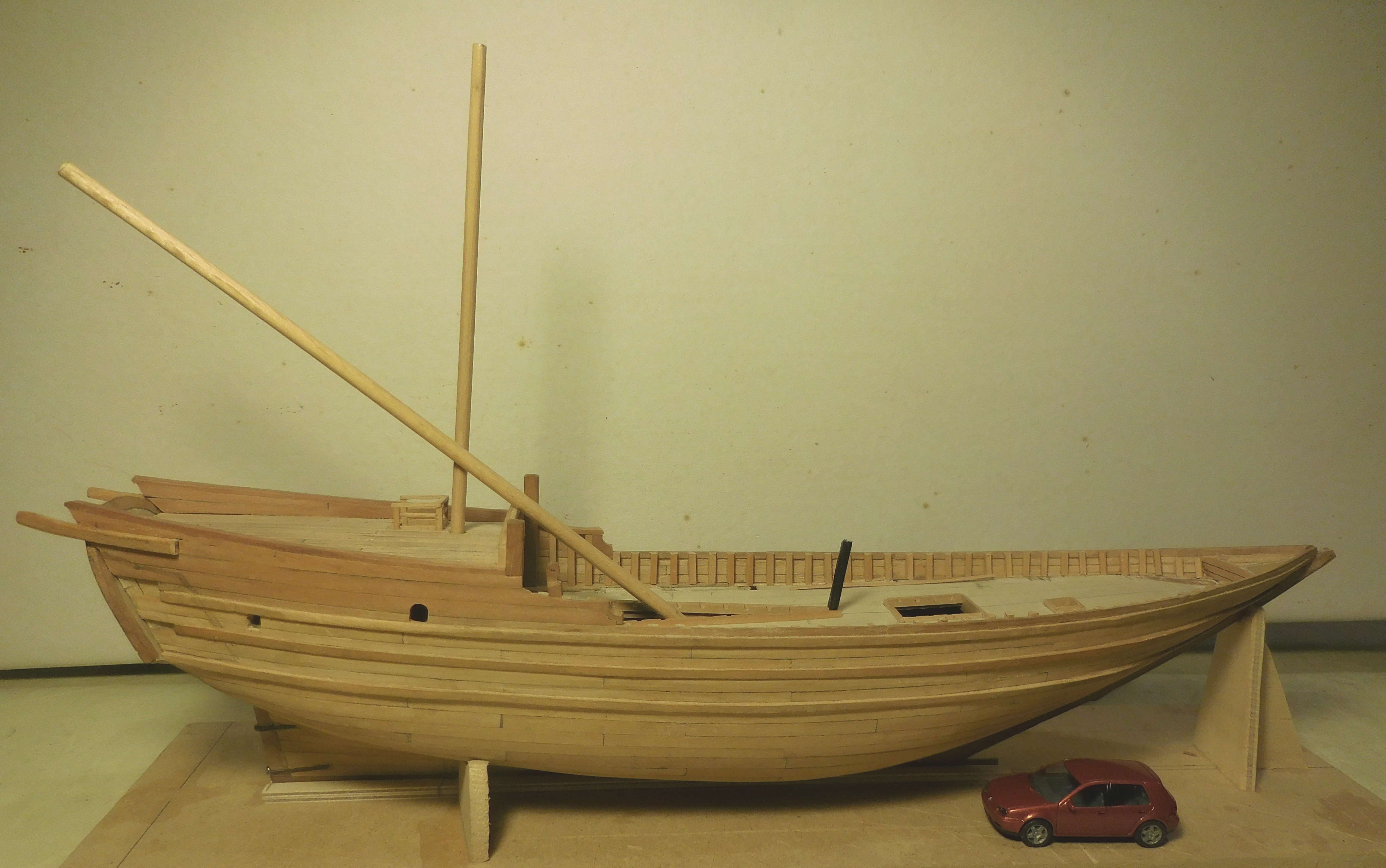
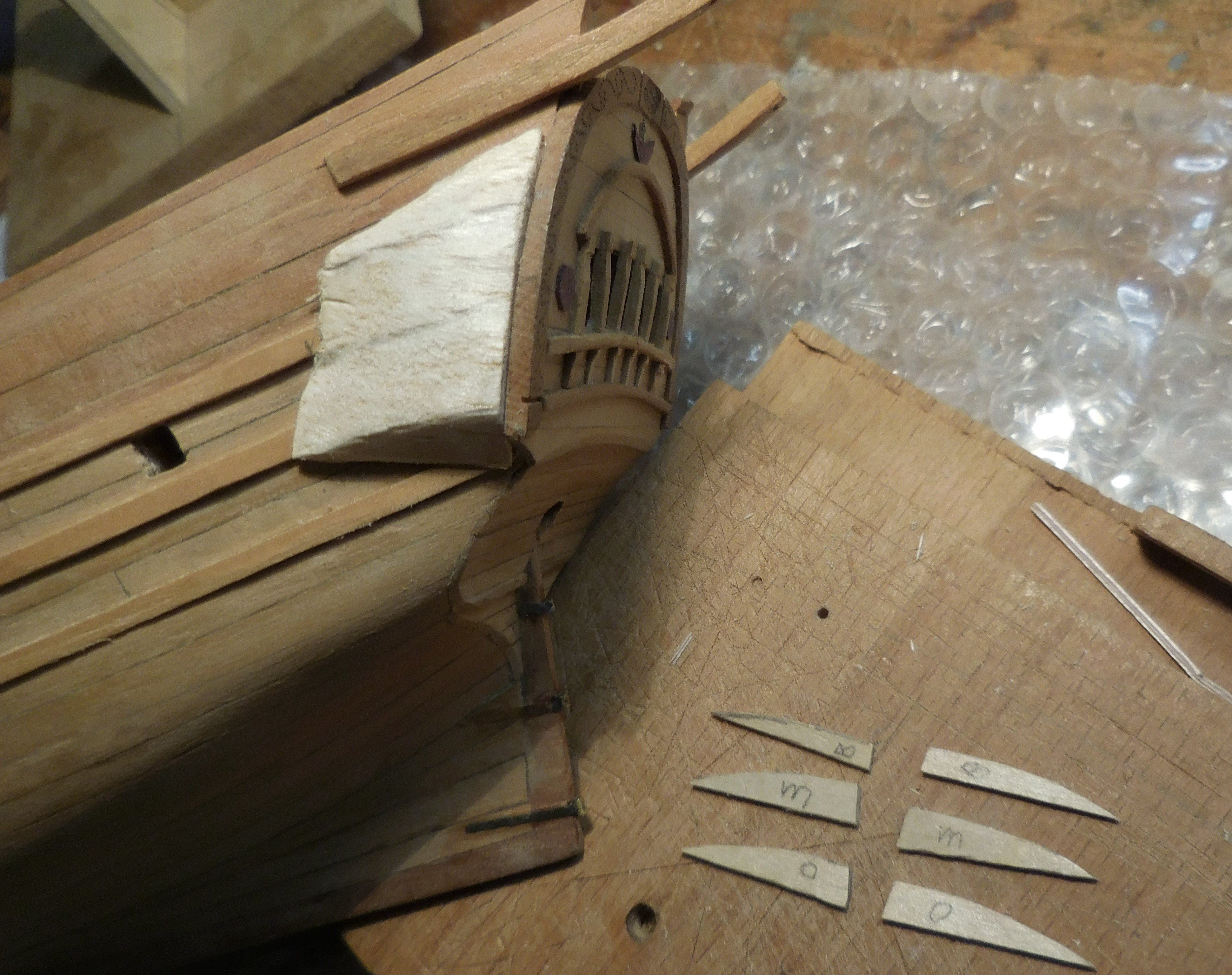
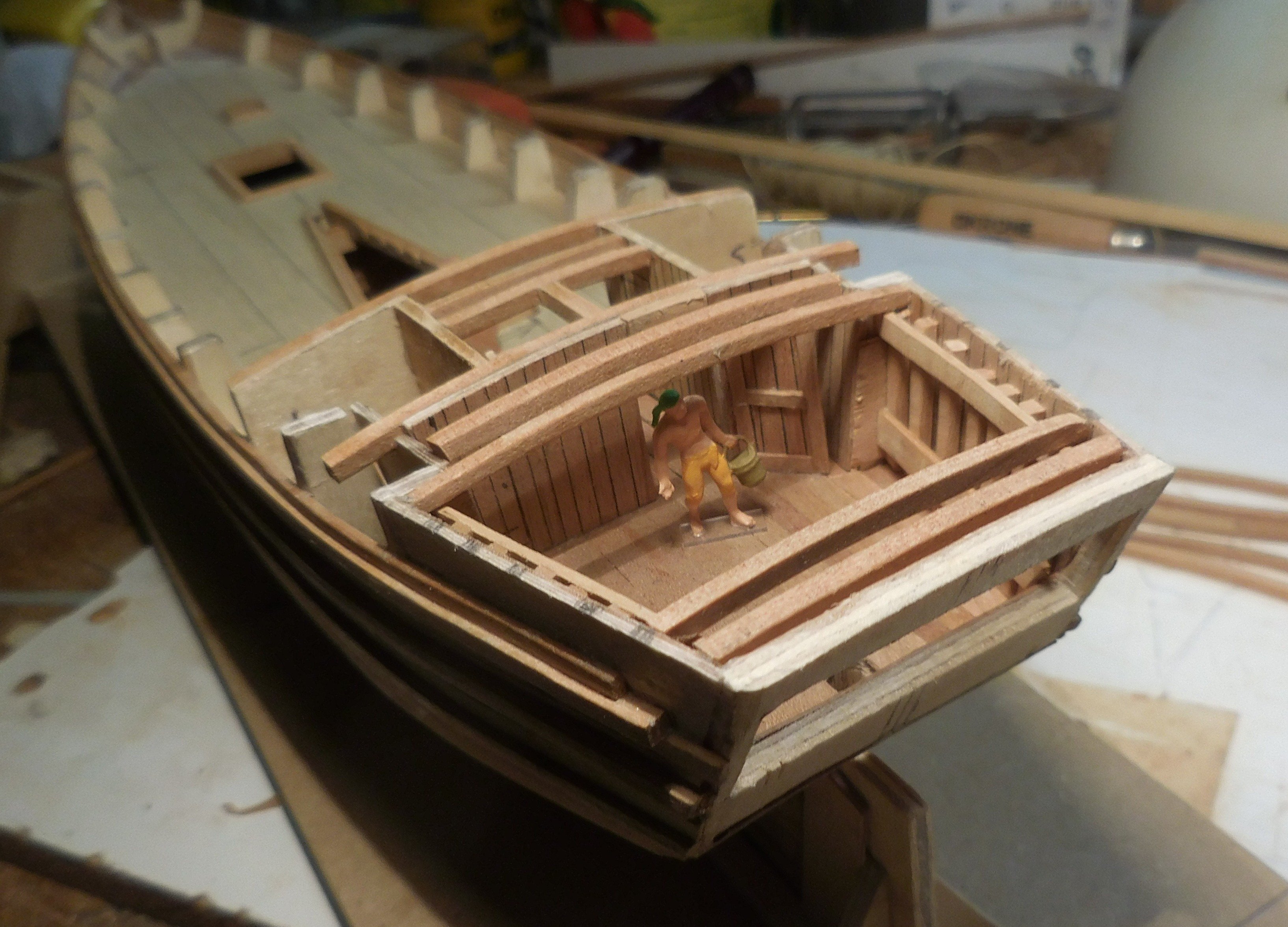
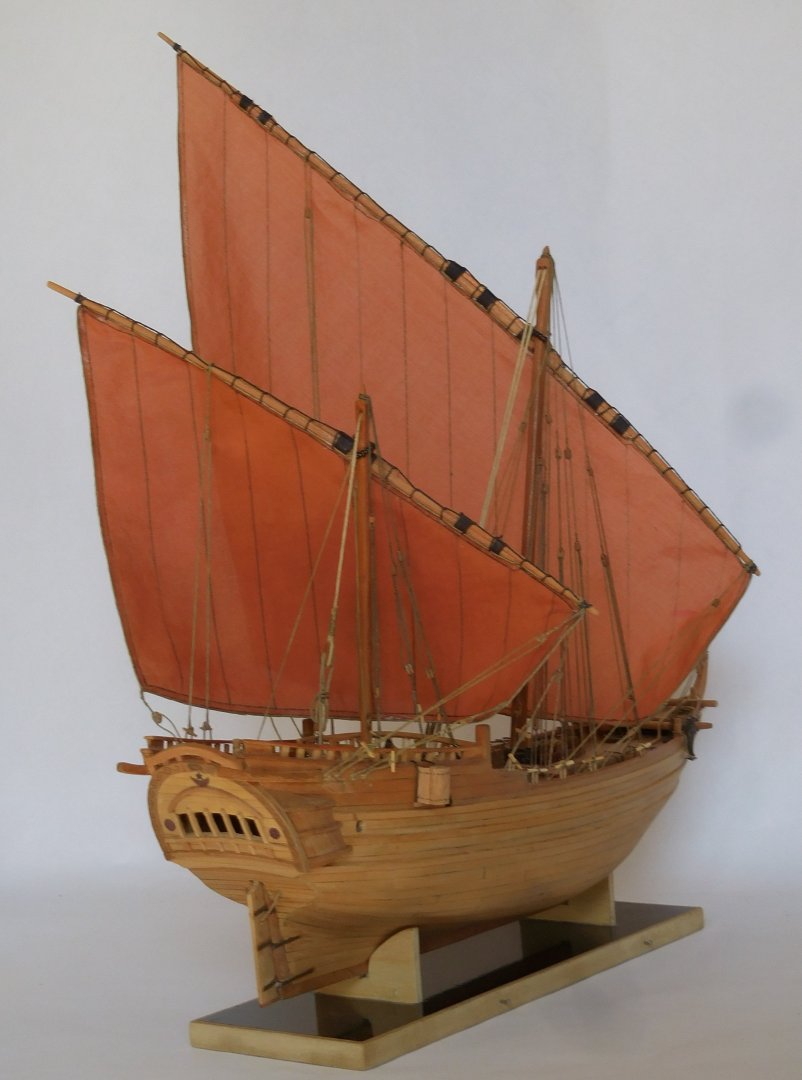
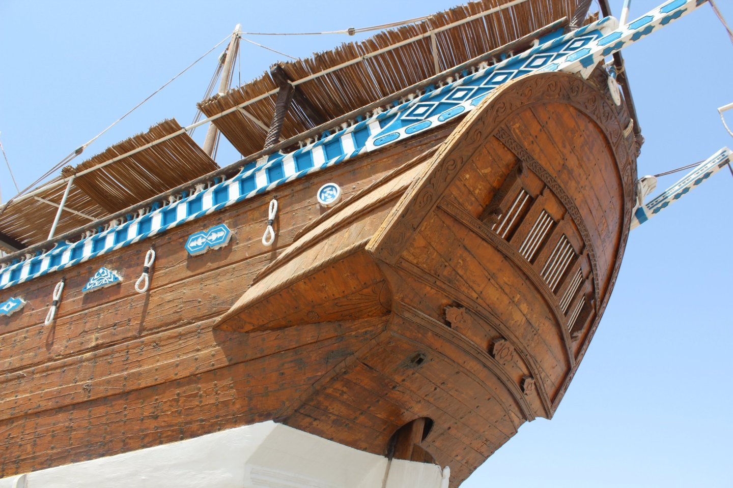
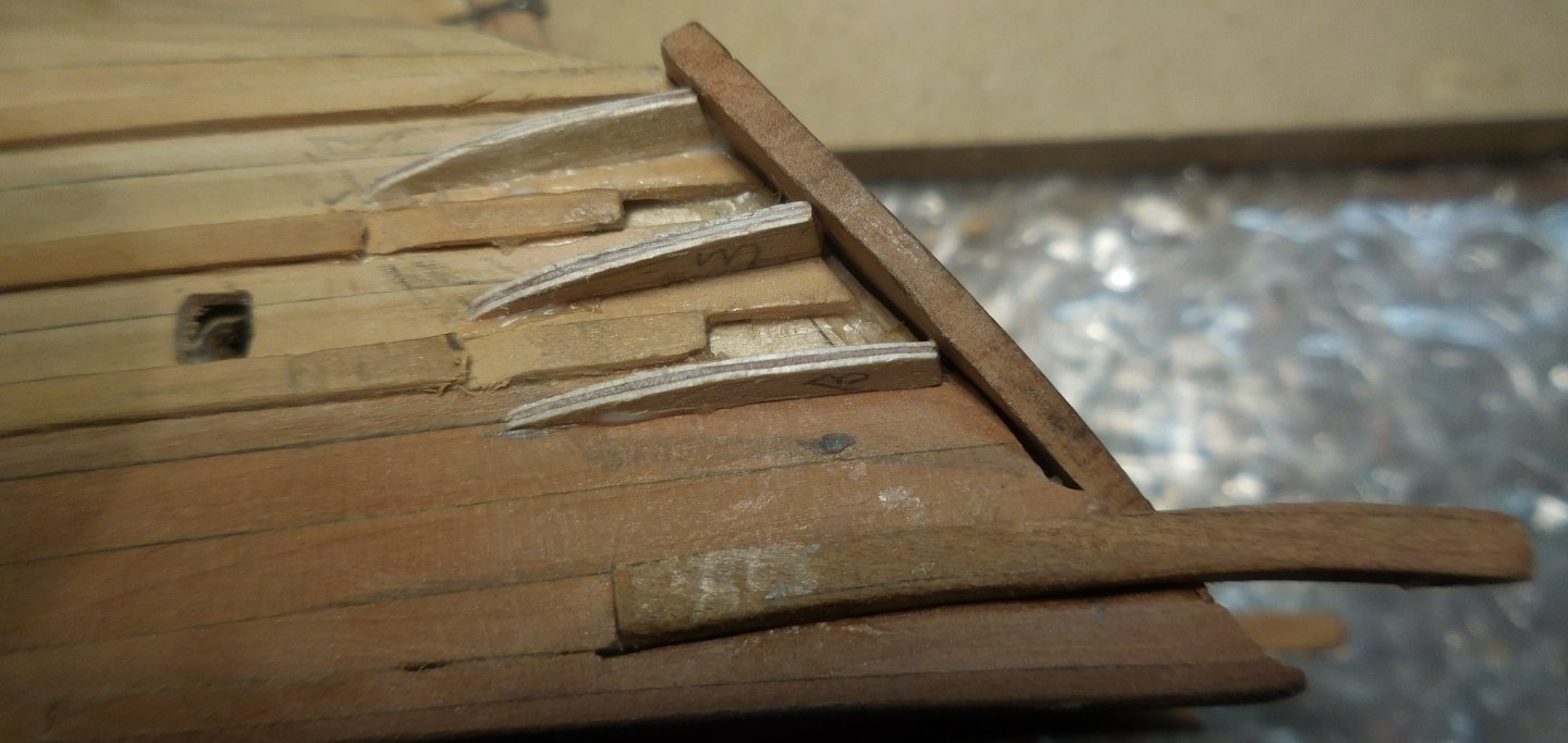
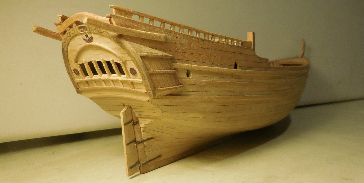
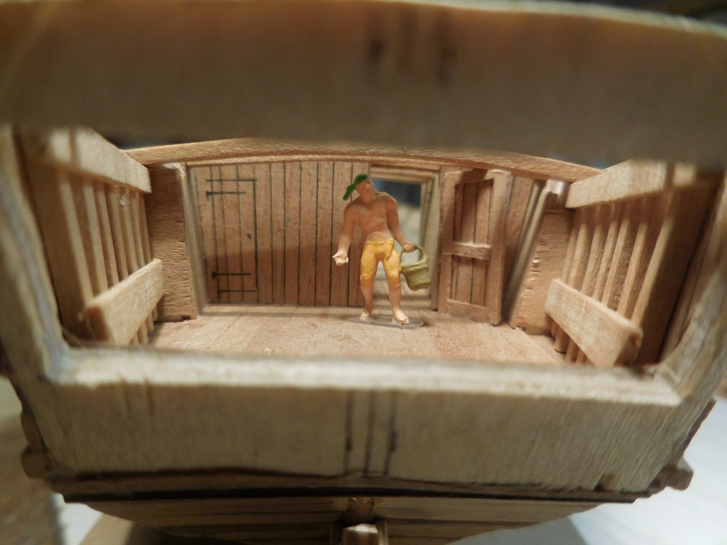
4 One of the still not fully clarified peculiarities of all ships in the Dhow family is the triangular cargo hold. No doubt it has to do with the removal of the mast during the period that the hull was cleaned on the beach after a return trip, for example to Zanzibar on the east coast of Africa. This is the situation. The short mast, indicated here in black, is attached to the ship. The main mast is tied to this. Detached, the mast can tilt backwards and be removed. But how exactly this happened technically is a mystery that I just can't figure out. I have asked everywhere, but everyone does not know the answer or avoids mentioning anything about it in descriptions (because they don't know either?). What we could trace is that that triangular opening became more rectangular as more and more Ghanjah's were equipped with diesel engines. It is possible that the winches that had to be used for removing the mast were also driven by this. Due to the triangular shape, the mast can easily be guided along the mizzen mast. The ships stood on the beach while cleaning the hull, tied to poles. The little car is on the same scale as the model. Each Dhow has two high vertical beams midships to which the heaviest piles were tied. The rest of the poles were then against the rubbing strakes. Why the mast had to be removed is also not described anywhere. I keep it on the ship being better balanced when it is on the beach. The sides of the stern look a lot like the English ships of that time. Here too, there are widening that suggest that it concerns the officers' toilets. The photo above is of the exhibited ship on the beach at the maritime museum in Sur (Oman). But whether that function is also intended for the Ghanjah is not clear to me. Here you can also see the vertical blue poles at the beginning of the aft deck. So the thick poles that had to keep the ship upright on the beach were attached to it. To the left below those poles a so-called "zuli". A toilet hanging outside the ship, characteristic of the Dhows in general. I hadn't set up those widening yet, and that was the next step. I first made a model of balsa wood that fit exactly on the ship. Lines were drawn on it that indicated the location of the trusses. The piece of balsa wood was sawn through on those lines so that I could determine the shape of the rafters. After this I was able to provide the room with planks. There are also two protrusions on the stern; the crane beams for lifting a sloop It is also striking on these ships that there is no clear rubbing strake. There are about three thicker planks sticking out that run along the entire length. Some photos show that there were often more than three. Constant

.jpg.c920589592f69baa388ef3c4824d761f.jpg)

-
Hi Roel, The ship Al Hashemi-II is apparently supposed to represent a Ghanjah (?) on a scale of about 3 : 1. It is a disproportionately large ship of which I wonder if it has ever sailed. In any case, it was built not so long ago and belongs completely in an oil country like Kuwait. The details on deck somewhat correspond to the actual equipment of a traditionally built Ghanjah, but are also three times larger than in reality. I prefer to stick to the data that can be found with the real ships. In Oman, too, much larger examples are being built nowadays, mainly for the benefit of the tourist industry. But they can't sail. I would like to point out the beautiful book: OMAN a seafaring nation. Published by the Ministery of National Heritage and Culture, Sultanate of Oman. 1991 This book honors great the traditional ships from their history and is a source for every researcher. Almost all types of the Dhow family are described in detail here. Also the entire history of their sailing. I think it's still hard to get now. Constant
-
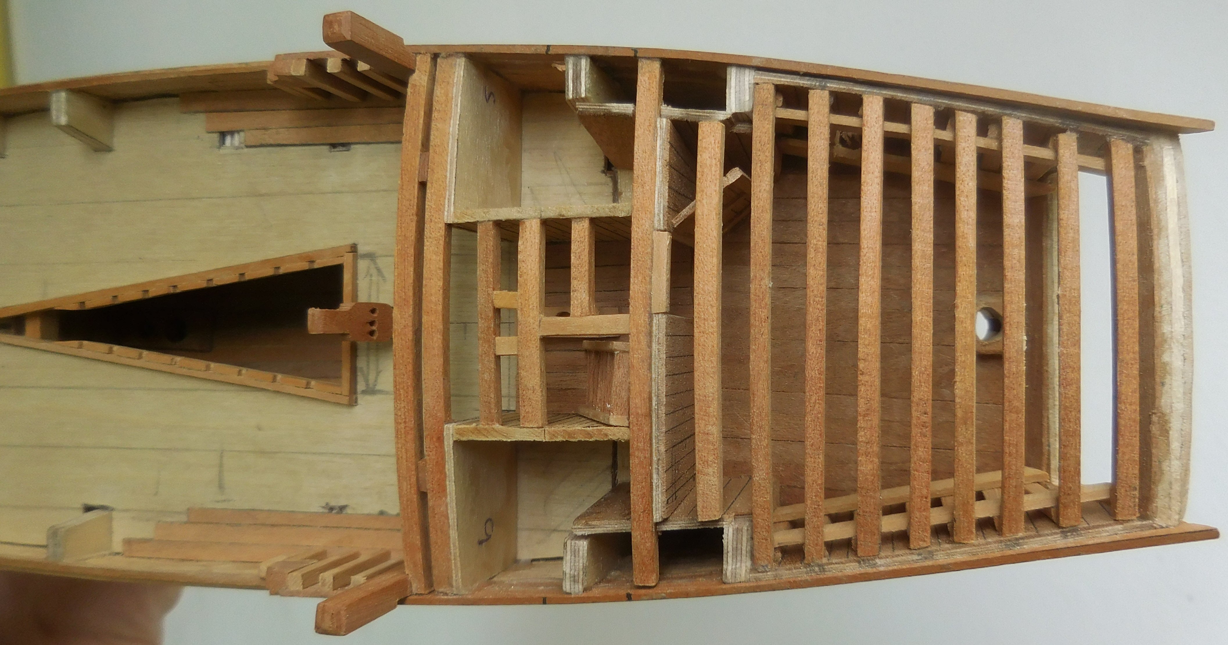
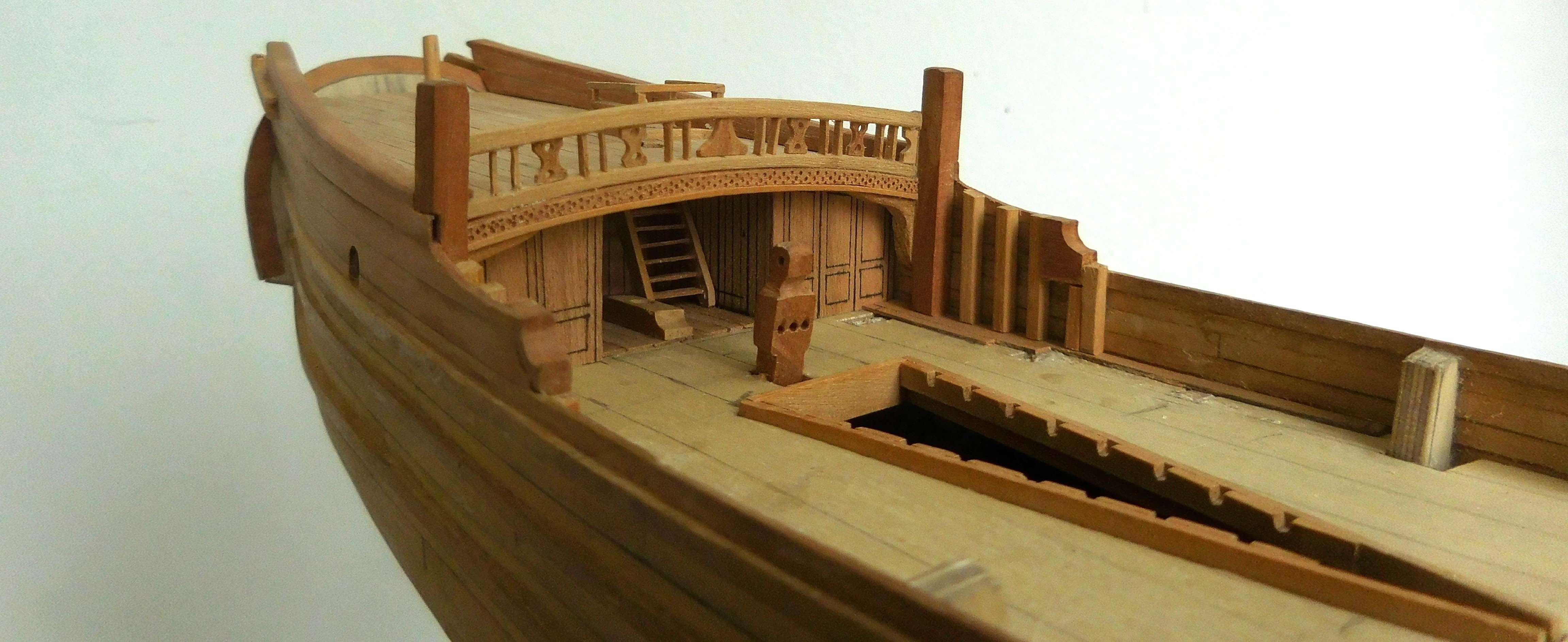
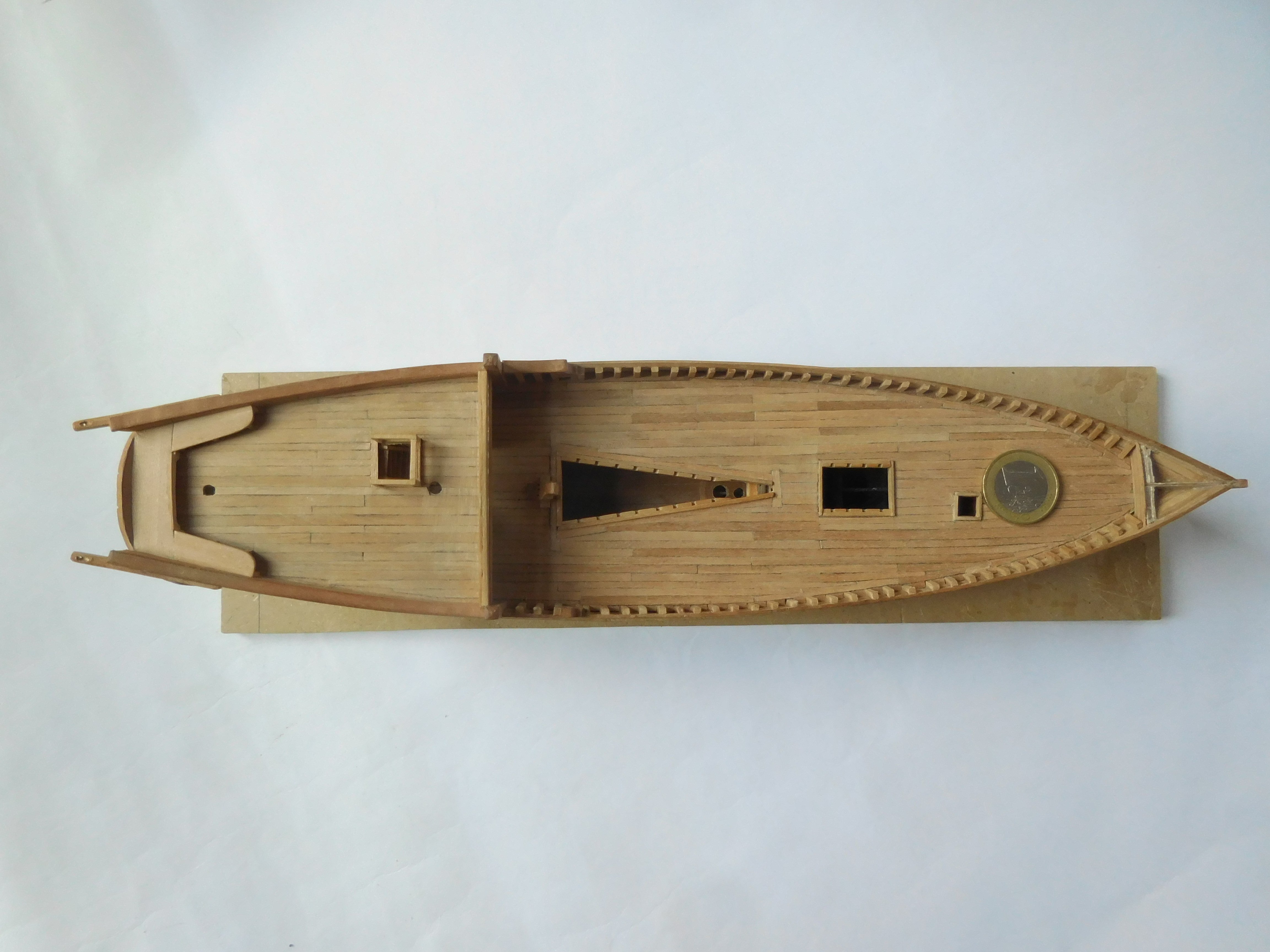
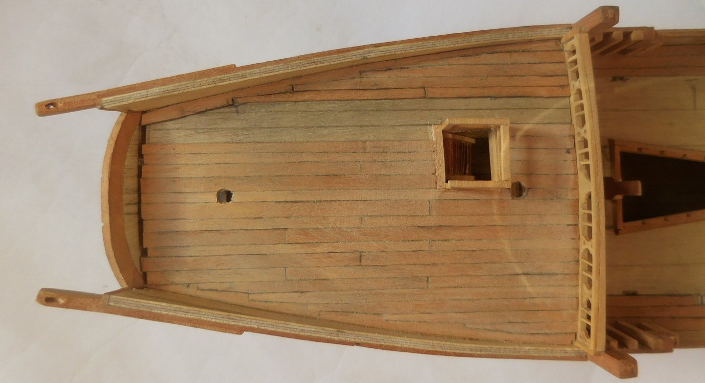
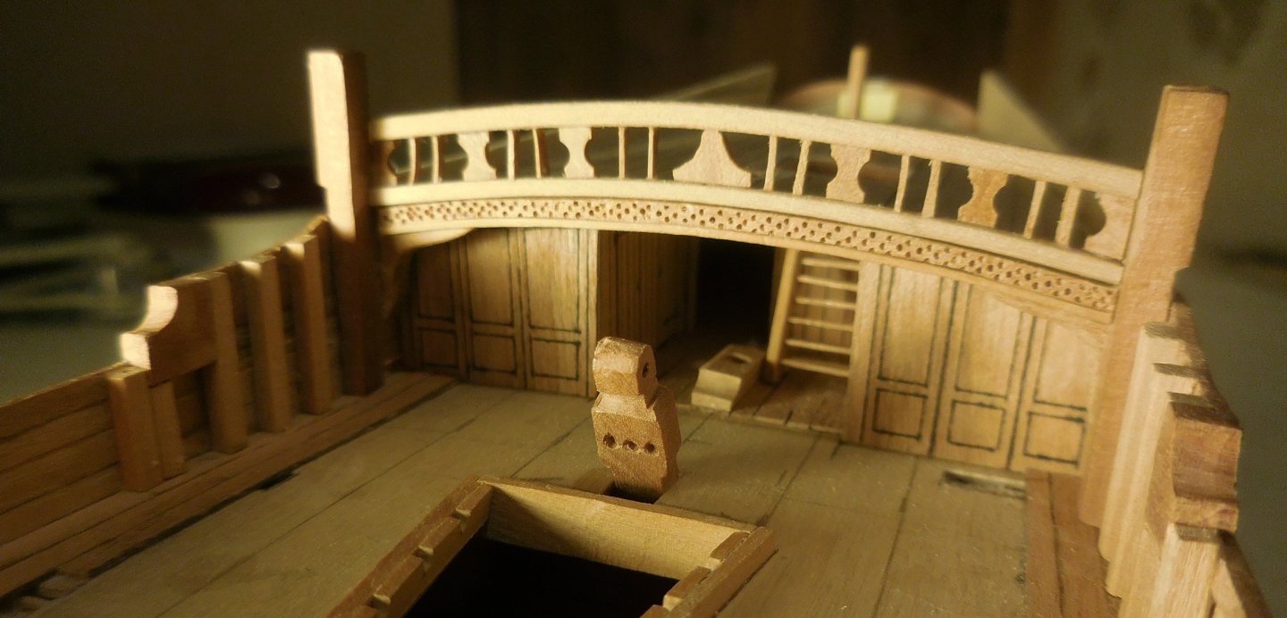
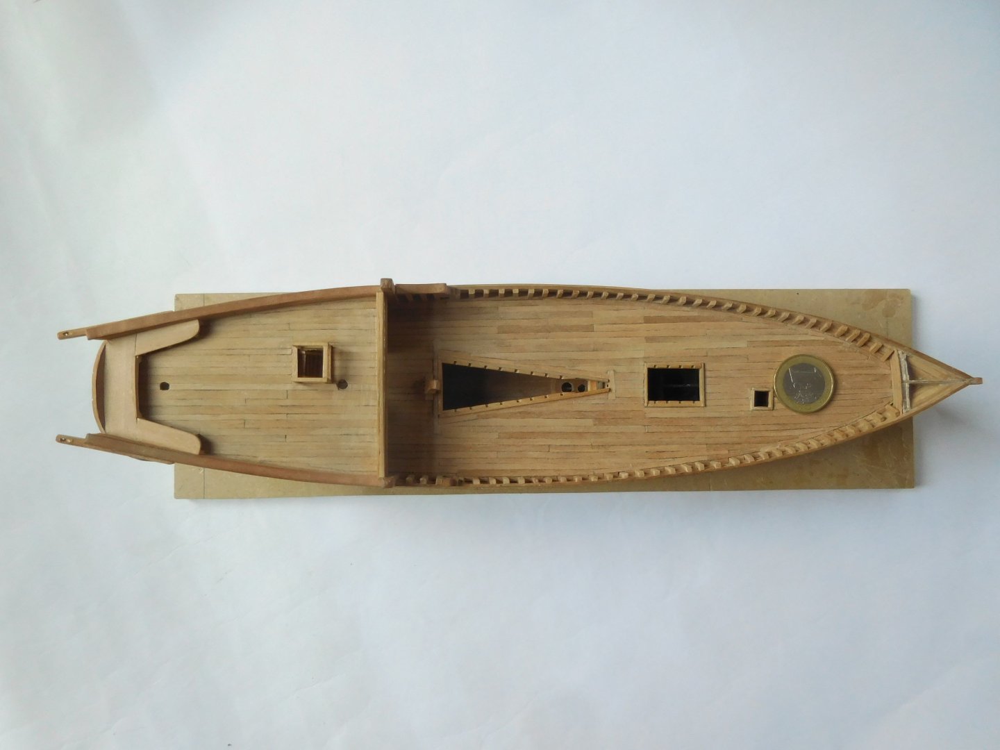
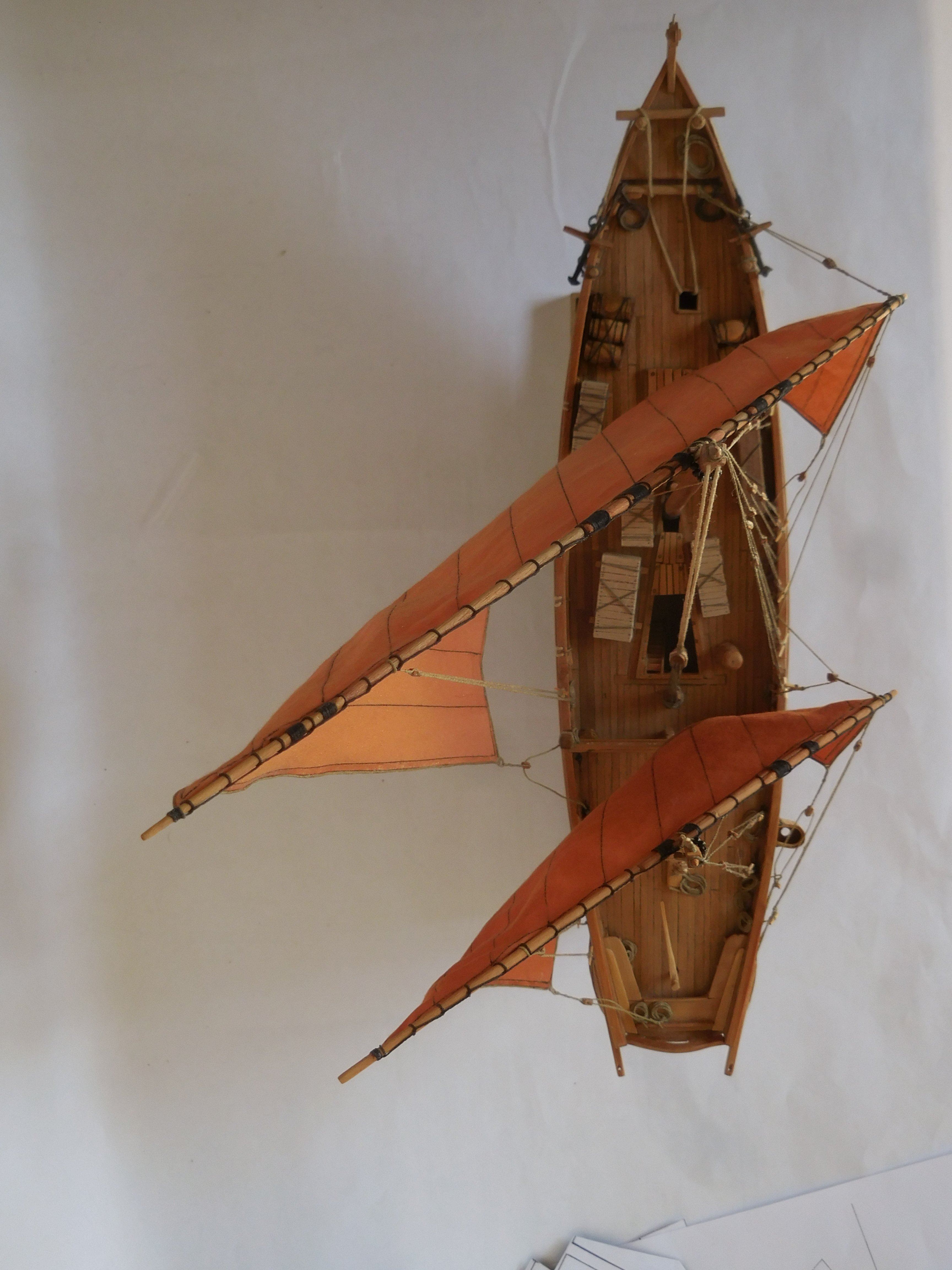
I made both decks from thinly filed slats of pear wood. In doing so, I deliberately did not take the same width everywhere. On the wharves, the tree trunks of unequal thickness were accepted and sawn. Because wood was expensive, nothing was thrown away, which necessarily meant that planks were not the same width and often tapered. You can still find this in old houses in the Netherlands that were built at that time. Of course, you also saw the same thing in Dutch shipbuilding. The almost boarded-up aft deck. Along the edges I have interlocked the planks in such a way that there are no sharp points that make nailing impossible. Again, graphite between the planks. The beams under the aft deck, which is still visible if you take the effort to peek through the windows of the transom. In front of the cabin two rooms and in the hall the stairs to the deck. The bulwark now had to be stripped of the thick reling struts of 3 mm plywood. By doing this piece by piece and immediately applying the struts in the correct dimensions, it remains a very sturdy whole. You can see this happening on the port side. I have roughly copied the decorations under the balustrade and the balustrade itself from detailed photos of the ship exhibited in Sur. Unfortunately, the decks and railings were provided with a kind of plastic sheet, so a number of details (which I did find on drawings of measured ships) are not visible. Here you see the bitt holding the yard in place by means of the halyard block. On the right a cast iron capstan. The blue/white painted pole is the attachment point for the poles when the ship is on the beach for cleaning the hull. So this ship was built in 1954. The top view in a certain construction phase. The 1 euro coin indicates how big/small everything is. On the aft deck the benches where the crew often stays during the long voyages. This is also where the tiller will be. The bow with the stylized head of a rooster, characteristic of the Ghanjah. Constant


-
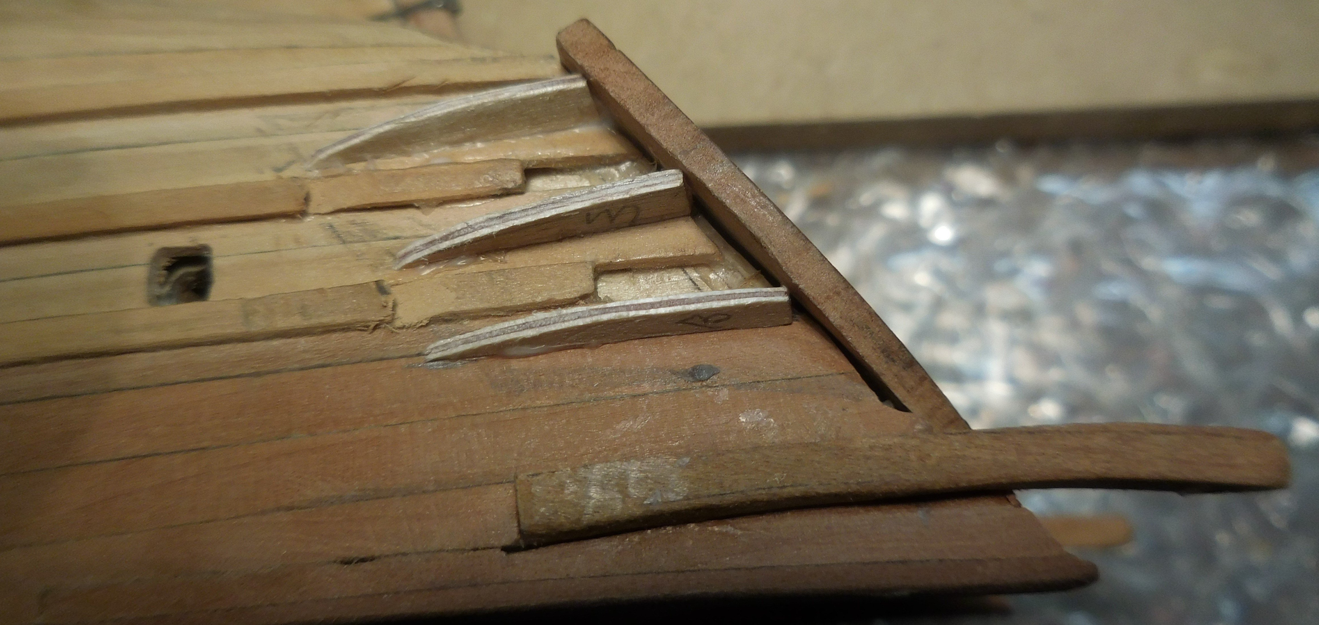
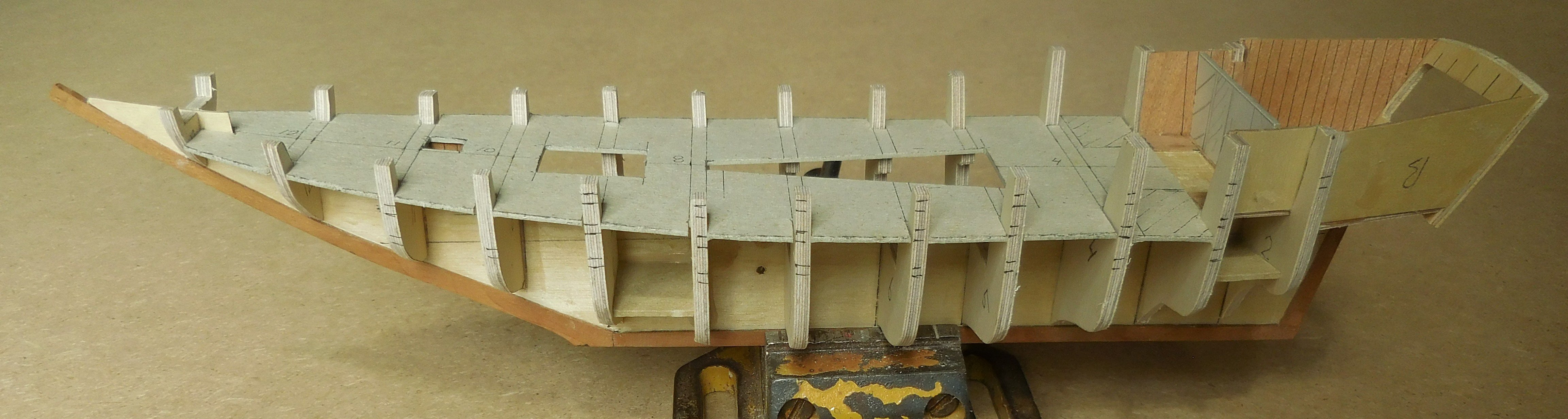
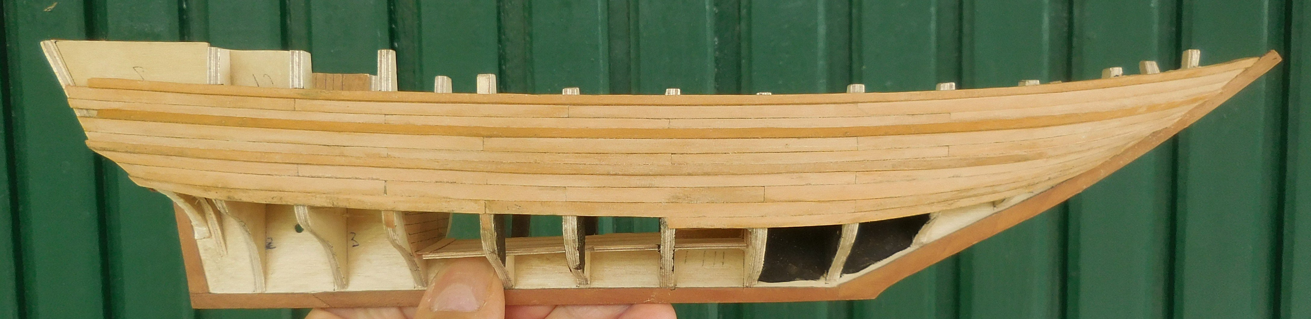
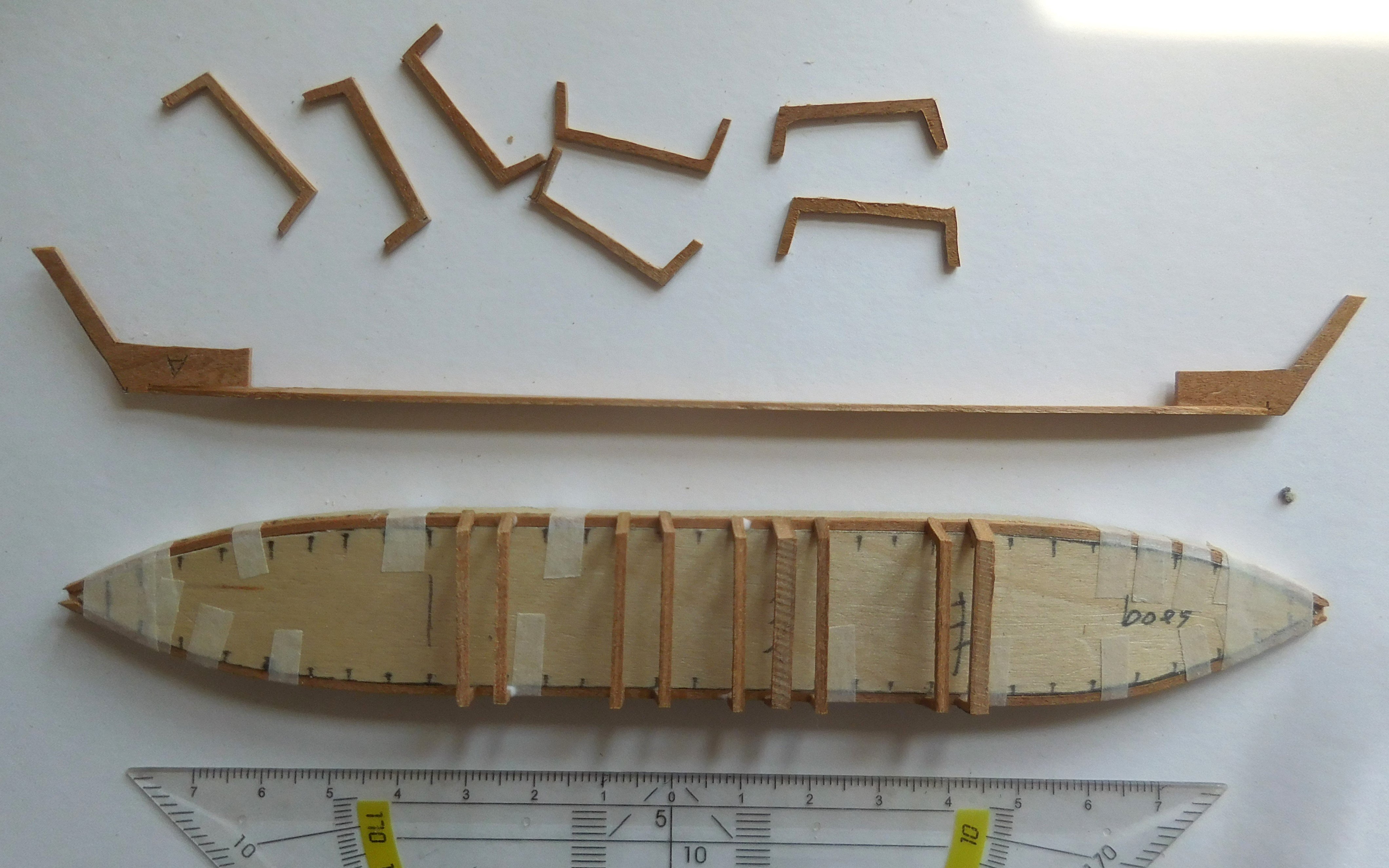
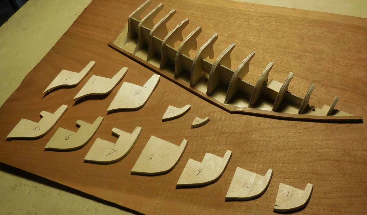
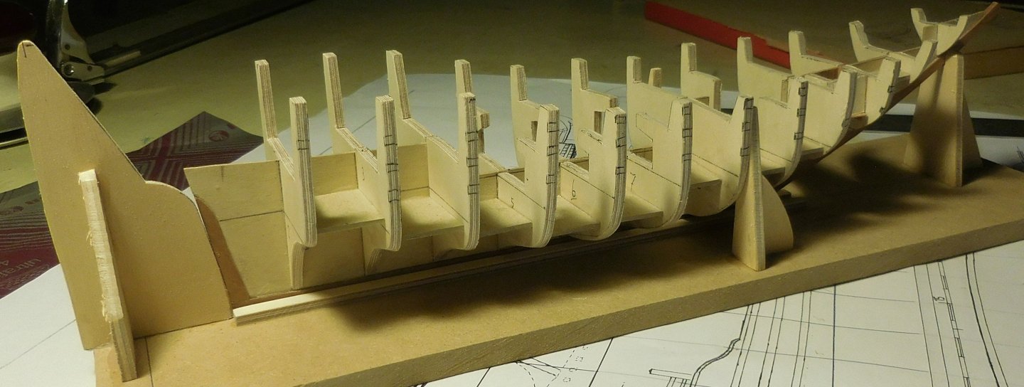
2 For the construction of the ship I used pear wood. I made the hull on frames of plywood, in the same way as I described in the construction of the early pinas, which I described earlier on this forum. This model is almost twice as large, while they are both built on the same scale. It started with making the semi-trusses from thick cardboard and I glued them to a piece of MDF. These were cut and filed until the right profile was created. The cardboard trusses were removed and I carefully traced the outline on 3 mm plywood. For the longitudinal bilge I used 1.2 mm thick plywood. Against that, so against the end wood, I glued the bow, stern and keel in 2.5 mm filed pear wood. The half-trusses were sawn out from one side and glued on. Then I filed a little more here and there to get the course right (now the diagonal filing of the rafters also played a role). By then holding small pieces of 3 mm against the filed trusses, I was able to draw, saw out and apply the correct trusses on the other side. The longitudinal bilge is in fact too thin to guarantee stability, deforming would be easy. That is why I glued small pieces of plywood between the rafters so that an undeformable whole was created. At that stage I also made the deck in thick cardboard, which was then taken over on 1 mm thick plywood. The interior of the cabin had to remain visible. I made the walls and against them came the extensions. The roof is slightly round and tapered so each deck beam had to be drawn separately for that. There is a corridor before you enter the cabin and small rooms to the left and right. In the meantime, I was busy planking the hull. Because I used 3 mm plywood, I was able to make/glue the connections of the planks on the rafters. Each end and longitudinal side of the planks was smeared with graphite before it was attached. That causes a lot of mess with gluing, but after sanding a nice black line is created. I sawed out the planks from a plank of 6 mm thick pear wood. On that board I drew lines every 1.5 mm. Then I sawed out the planks with a jigsaw on those lines. This created planks of about 1.2 mm that I filed down to about 1 mm. The 1 x 6 mm planks were ready for use. On the hull I attached the planks that in reality were never more than 7 meters. On the scale used, they had a maximum length of 80 mm. The stern was a different story. There are quite a few known images, and they are all different. So I actually chose an average design. I sawed out the round arch and decorated it with pinpricks and smeared it with graphite after which I carefully sanded it off. I made the crescent moon and the octagons from very thin filed coromandel wood. I drew the black star on it. The rubbing strake looks different from that of Dutch ships. In most English ships of that time, the hull planks bumped against the planks of the wulf. A method that was adopted by the builders of the Ghanjahs. In Dutch ships, the planks continue. I made the rudder gudgeon braces in the same way as I described with an early pinas, some time ago on this forum. The finishing of various parts on and on the deck is a story for the next episode. If you still want to see photos of Ghanjah's in person, you can search for them extensively on the internet. Constant


-
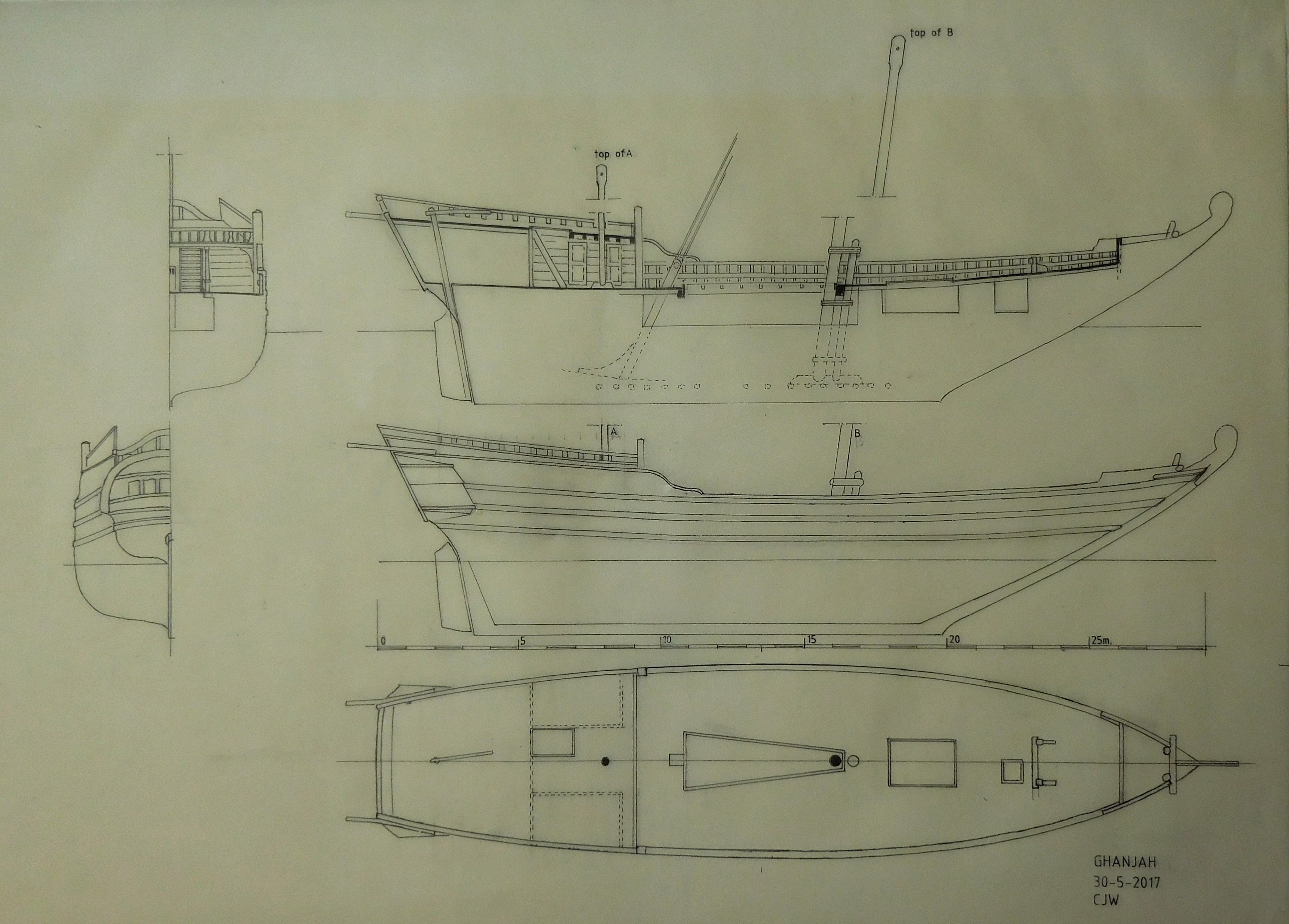
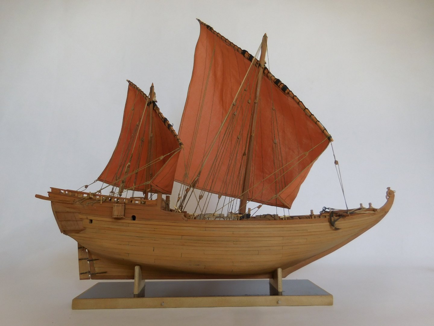
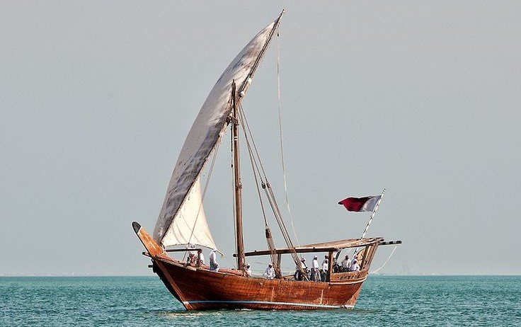
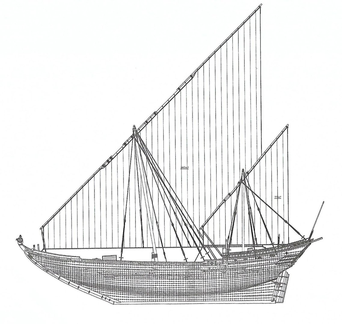
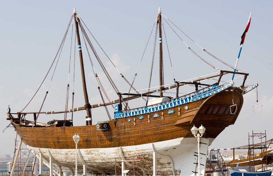
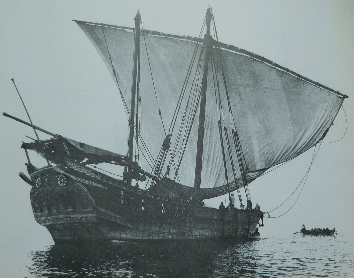
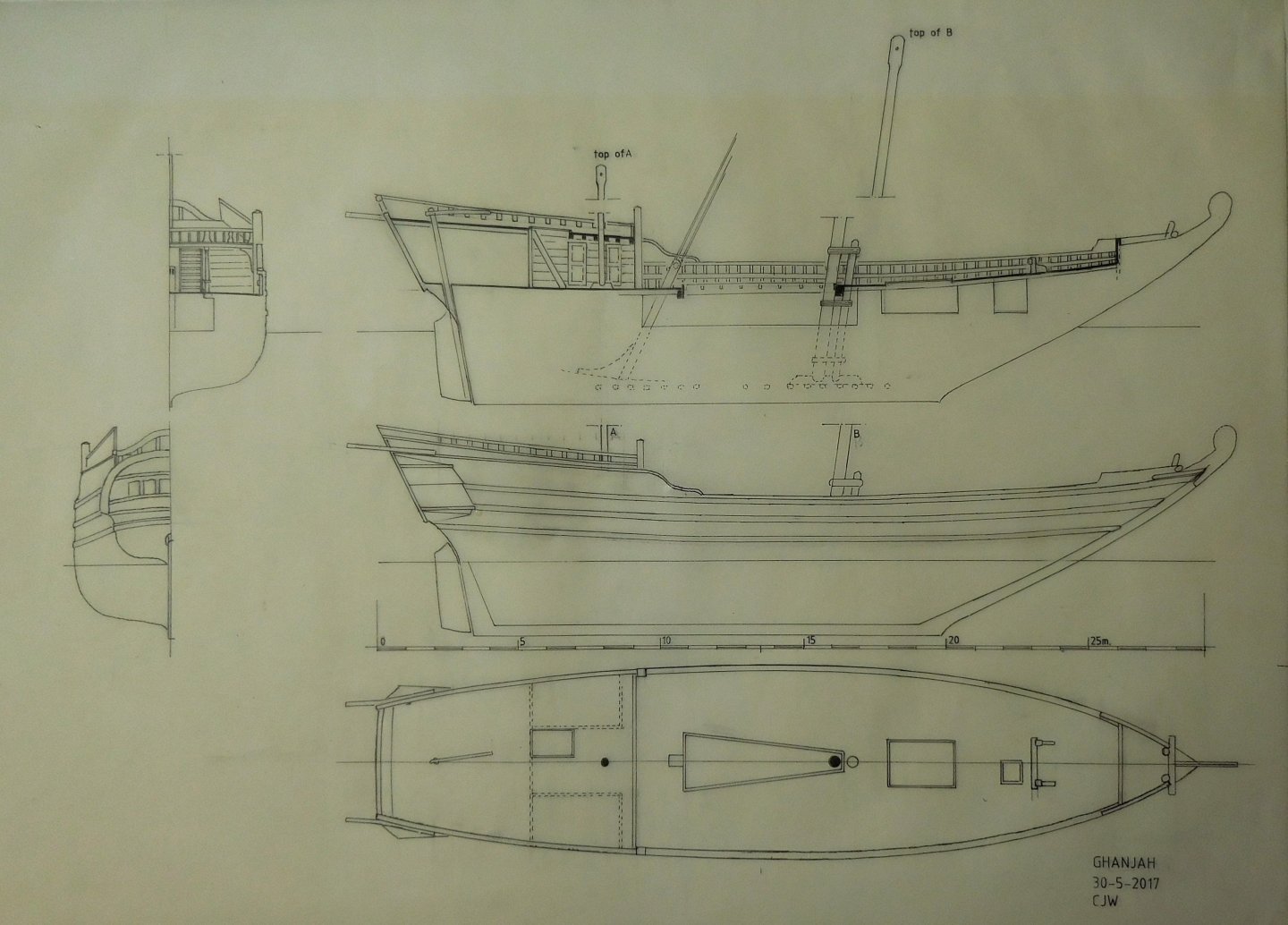
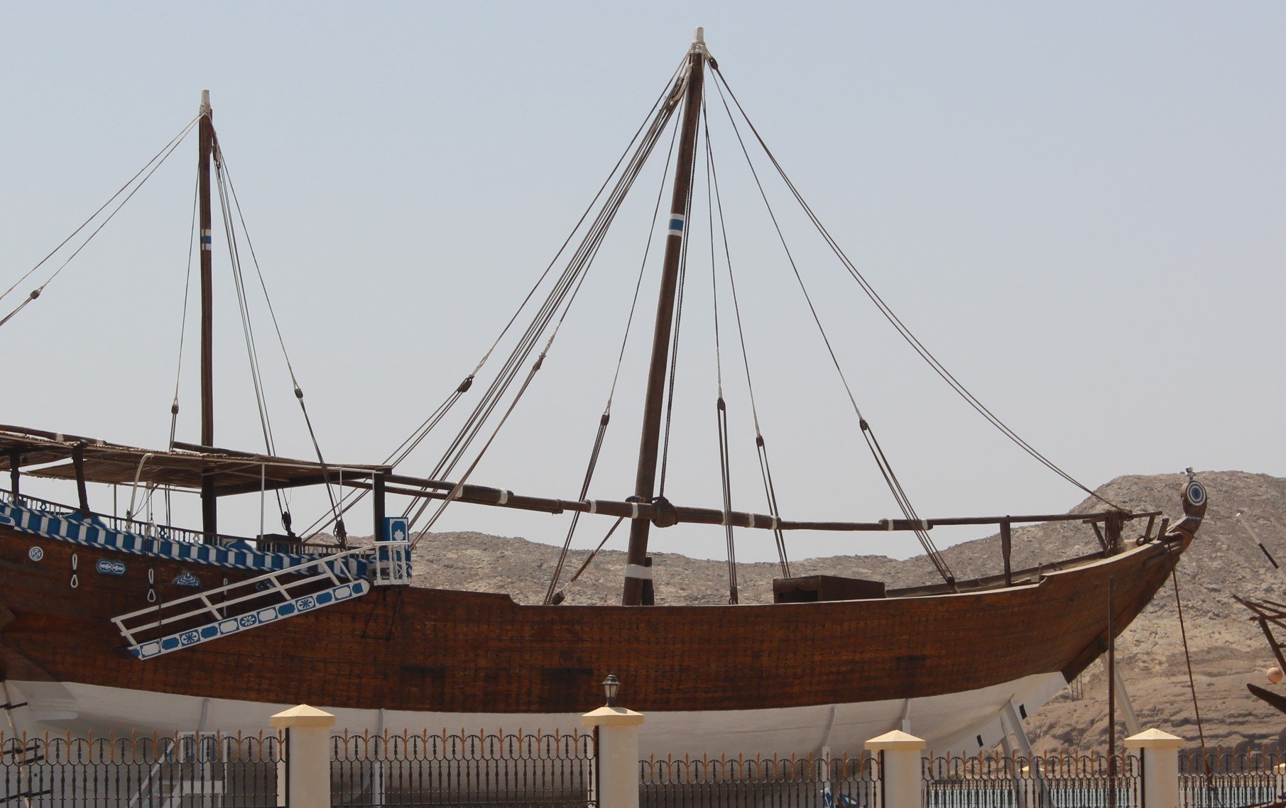
1 I started with this model in 2017. I had already described the entire construction in 2019 on the Dutch Modelling Forum, but because this ship is mainly a ship outside the collection of Dutch ships, I decided to publish it again on an international forum. A Ghanjah belongs to the family of the Dhows. Ships found in southeastern Africa, around Oman and the Persian Gulf. The Gahnja, the Kotia and the Baghla are the three largest ship types within the family. I obtained the drawings for the construction from the collection of measurements of antique ships of Admiral Paris, around 1830. Furthermore, many photos of one of the last existing Ghanjah's that is exhibited at the maritime museum of Sur (Oman) were helpful. I will come back to this ship in detail in this story. A photo from not so long ago. This was the main reason why I was impressed by this magnificent ship. The sturdy shapes, the gigantic sailing..... They were built from the beginning of the 19th century until the last examples that were built in 1954 (!) according to methods that have hardly changed in the meantime. The transom is strongly reminiscent of English ships, which were repaired and maintained in the same region, time and shipyards, where these ships were also created. A Ghanja at anchor with sails lowered. As can be seen, this is about Latin sailing. After intensive preliminary research, many questions remained, which have now been partly answered by photos on the internet of specimens that were still sailing and exhibited. Various books and accurate contemporary measurements of the ship in Sur and welcome data from experts also made it possible for me to start. The drawing that I made in advance based on existing drawings and data. If I build such a ship again, I will take the angle of the bow a little less, it is a bit too sharp here. Mistake afterwards. The anchor bitt here does not belong there, after closer examination. In 2019 I took the model to the model exhibition in Bataviastad, and there I met a visitor from Germany who put me in touch with the author of a book about research into this ship. Intensive exchange of data followed and we were able to solve a few ambiguities together. Constant
-
Hi Tom, Do not lay the grain of the several pieces of veneer in the same direction. Of course that will not work. Constant
-
There was a question about the recoil of the cannon when it was fired. In the side walls of the shooting niches, no traces of iron anchors to secure the cannons have been found. That seems a bit strange given the recoil and reversing of the guns. I found a video about firing a replica of a cannon from the Mary Rose. The cannon used is heavier in caliber than the replica I made and the recoil must have been greater there. It is clear to see on that video that the backlash was not that intense at all. I think that with the replica in the Bourgonjetoren in Zutphen, that recoil could easily be absorbed by placing sandbags behind the wheels and the vertical beam https://www.youtube.com/watch?v=G3bR9qN6HYY Constant
-
8 In the previous post, something went wrong at the end. Here are some more pictures to end this topic Thanks for all your likes! Constant
-
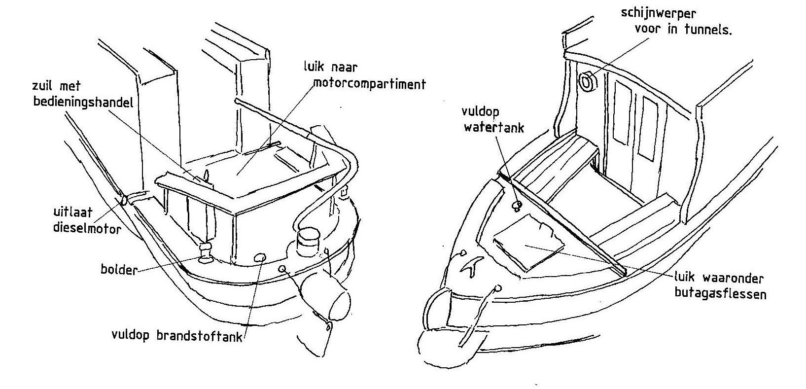
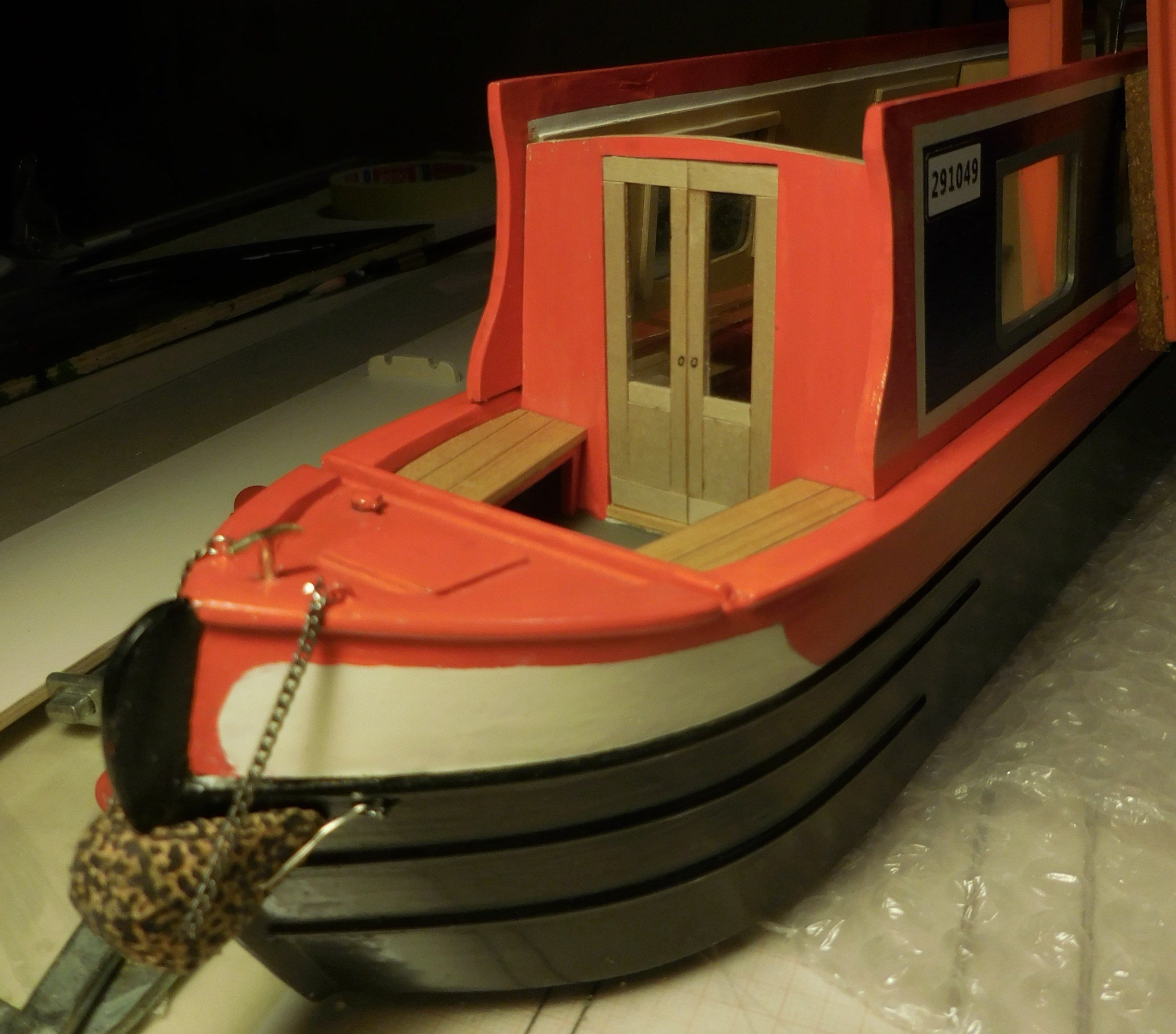
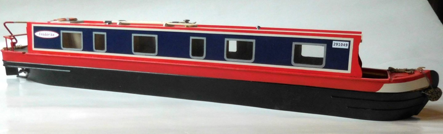
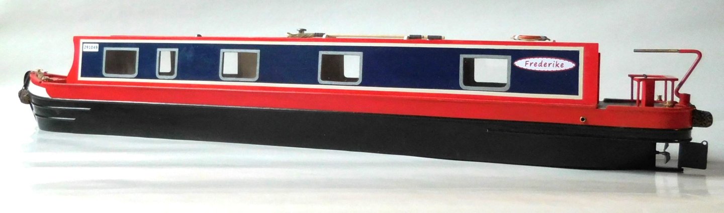
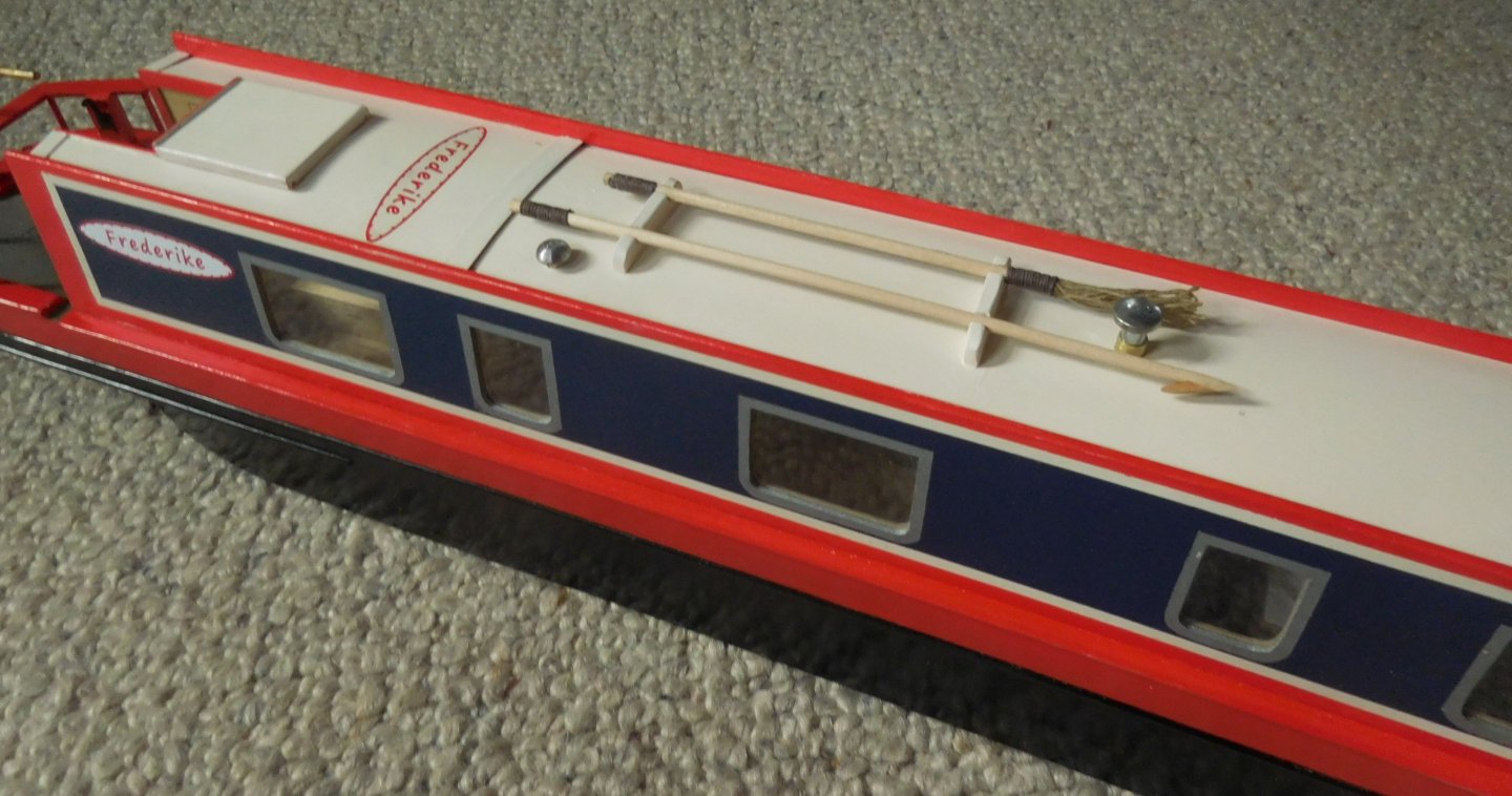
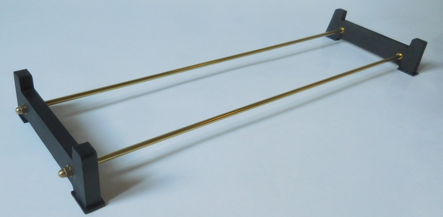
7 Zuil met bedieningshandel = Column with service handle. Uitlaat dieselmotor = diesel engine exhaust Bolder = Bollard Vuldop brandstoftank = Fuel Tank Filler Cap Luik naar motorcompartiment = hatch to engine compartment Vuldop watertank = Water Tank Filler Cap Schijnwerper voor in tunnels = Floodlight for tunnels Luik waaronder butaglasflessen = Hatch to butane gas bottles. On the roof and on the side walls the name of the boat, in this case that of the client's wife. On the front on the side panels is the mandatory number for all boats. In this case, it's my own date of birth. The model stands on a base of two baffles between which are copper threaded rods in brass tubes. Constant


-
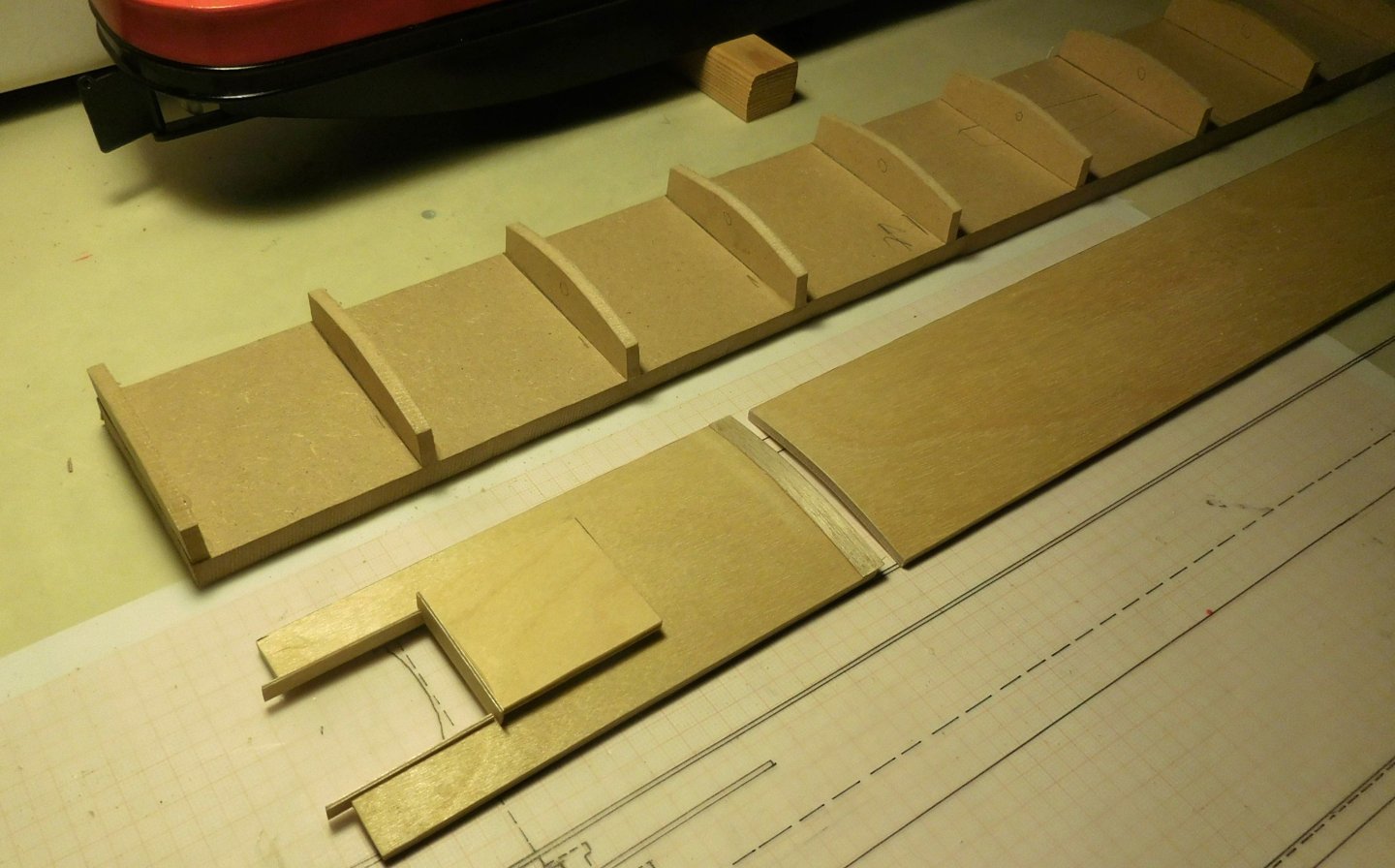
6 The last major part was the roof on the cabin. I made it in two parts. This roof is slightly curved. It consists of three layers of 0.6 mm thick plywood. These were fixed on a bent mould. Between the layers came the wood glue. After drying, that curved shape remained. In the photo, the mold is visible next to the parts of the roof. The short part is fixed and the long part is removable to view the interior. This fixed part is necessary to ensure the stability of the model. In the roof there is a sliding hatch that closes at night, and is open during the day, which is necessary to be able to access the stairs. On the roof of the cabin there is a lifebuoy and a boathook according to regulations. A deck mop is also an indispensable part. Furthermore, the various ventpipes for the toilet, shower and extractor hood of the kitchen are located in the right places. Constant

-
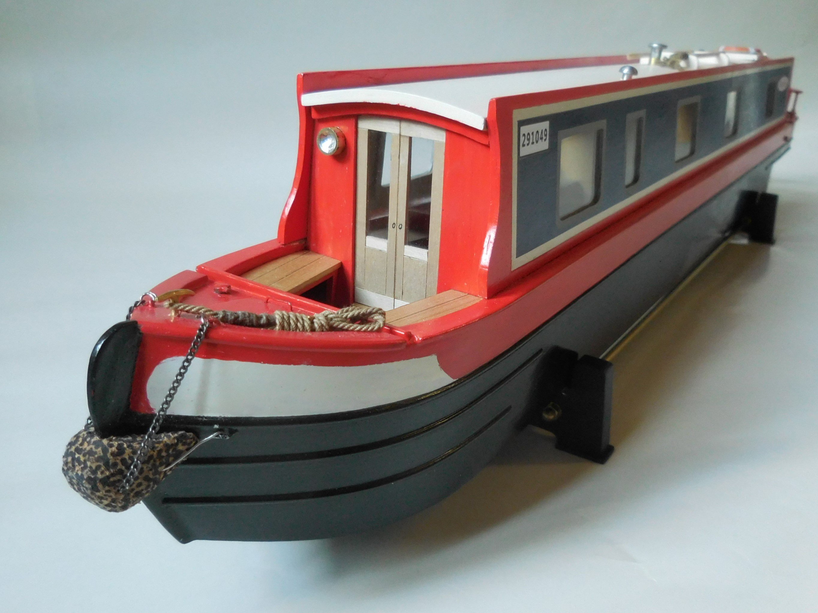
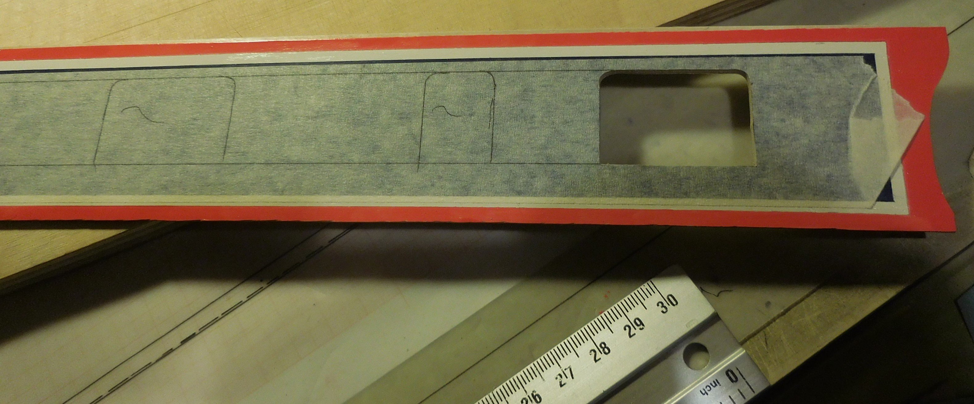
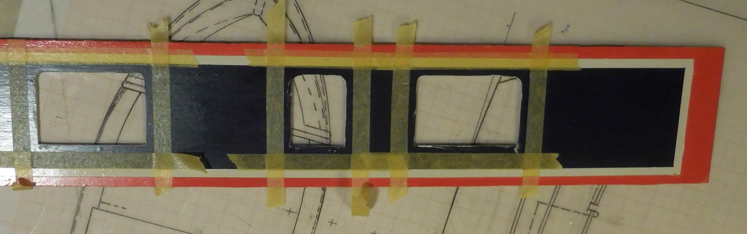
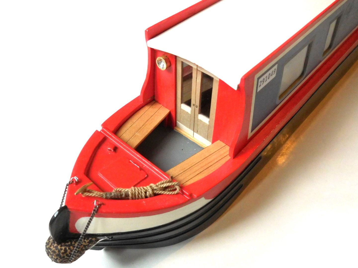
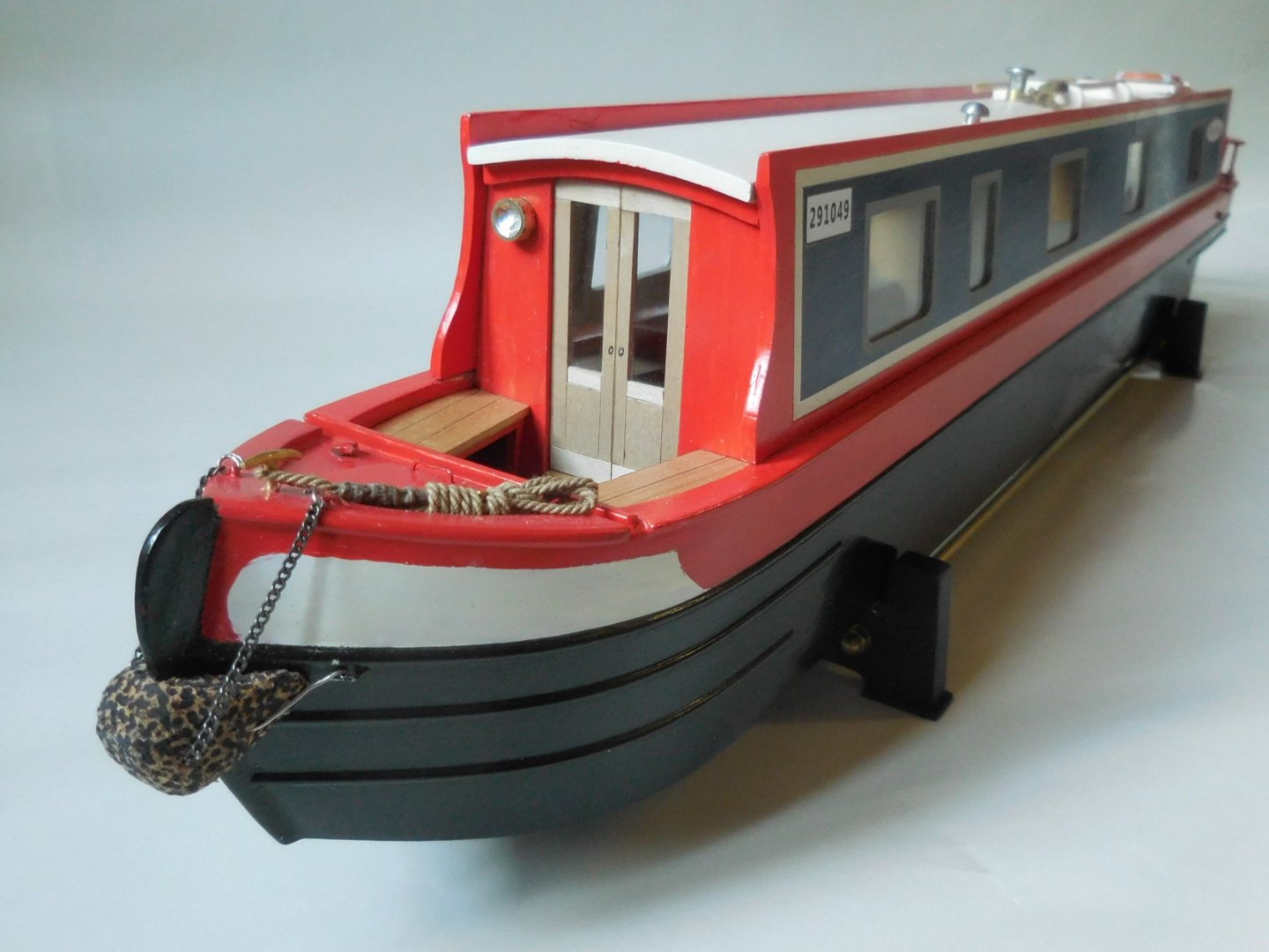
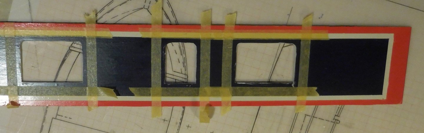
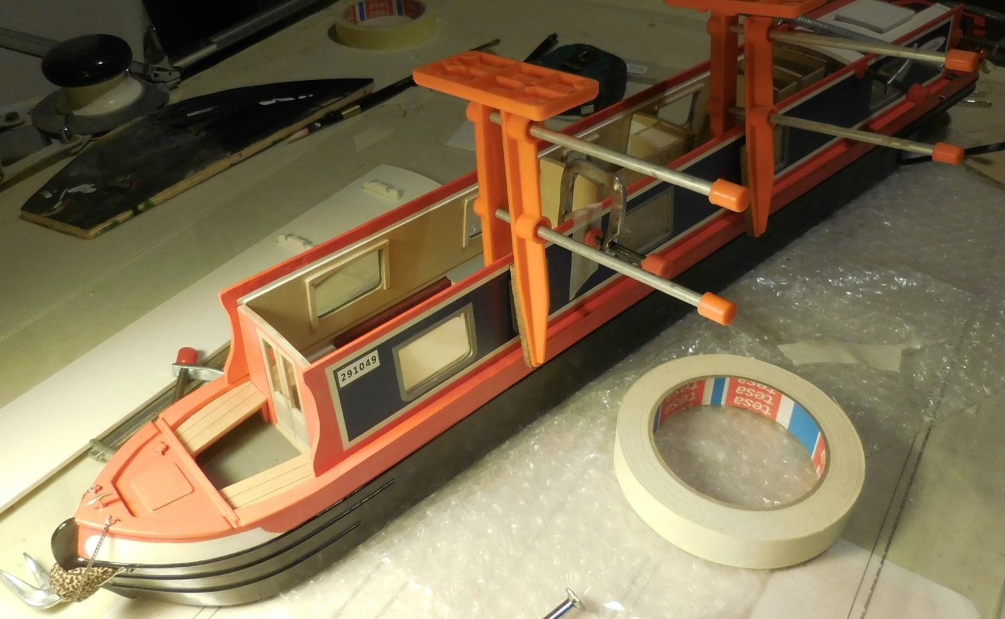
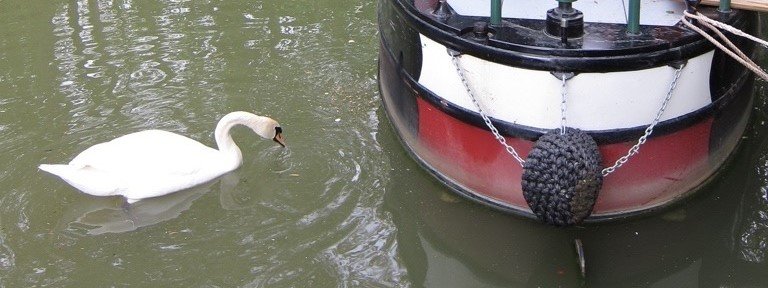
5 The side walls with the windows each consist of three layers of plywood. The outer one is 1 mm thick, the middle one is 1.5 mm, and the inner one is 0.8 mm. In the middle layer, sheets of perspex of 1.5 mm are included. The outer and inner layers have been painted/varnished in advance and temporarily attached to each other. On the blue background a layer of tape on which the windows were drawn, which were then sawn out. The frames of the windows were taped and painted. In the middle layer, slightly larger openings were cut out in which sheets of perspex. After gluing those three layers together, the windows became visible as glass and the side panels were ready to be mounted. The front and rear were then painted and the two bulkheads of the cabin were made and finished. In both partitions there were doors with perspex as glass After that, the side panels could be installed. Inside the cabin, everything was completed. Fenders were installed at the bow and stern, especially necessary so as not to damage anything in the narrow locks during the locks. In the model, they are pieces of cork that have been cut into the right shape. They are attached with chains and rods. Constant


-
Hi Tom, I think you are building a beautiful boat. But may I perhaps make a small point of criticism? You use plywood for the rafters. That comes into view and then I find it disturbing that you can see the three layers of wood so clearly, especially when they are varnished. This is easy to avoid. Simply make your own plywood by gluing together a number of layers of veneer of the type of wood you find suitable. If you cut the trusses from it, the ends are completely even. The best way to do this is to use two flat planks, for example 12 mm plywood. You provide each of them with cello tape on one side to prevent the glue from adhering to the boards. Then you put the required amount of pieces of veneer between those planks, provided with wood glue, best is to dilute that glue a bit, Then you clamp the planks firmly together and let it dry for a long time. The latter is important because it causes the glue to dry a bit slowly in the air. In this way, you can also determine any thickness of trusses, without being bound to the standard sizes of the plywood. All these small trusses are made according to the above method succes Constant

-
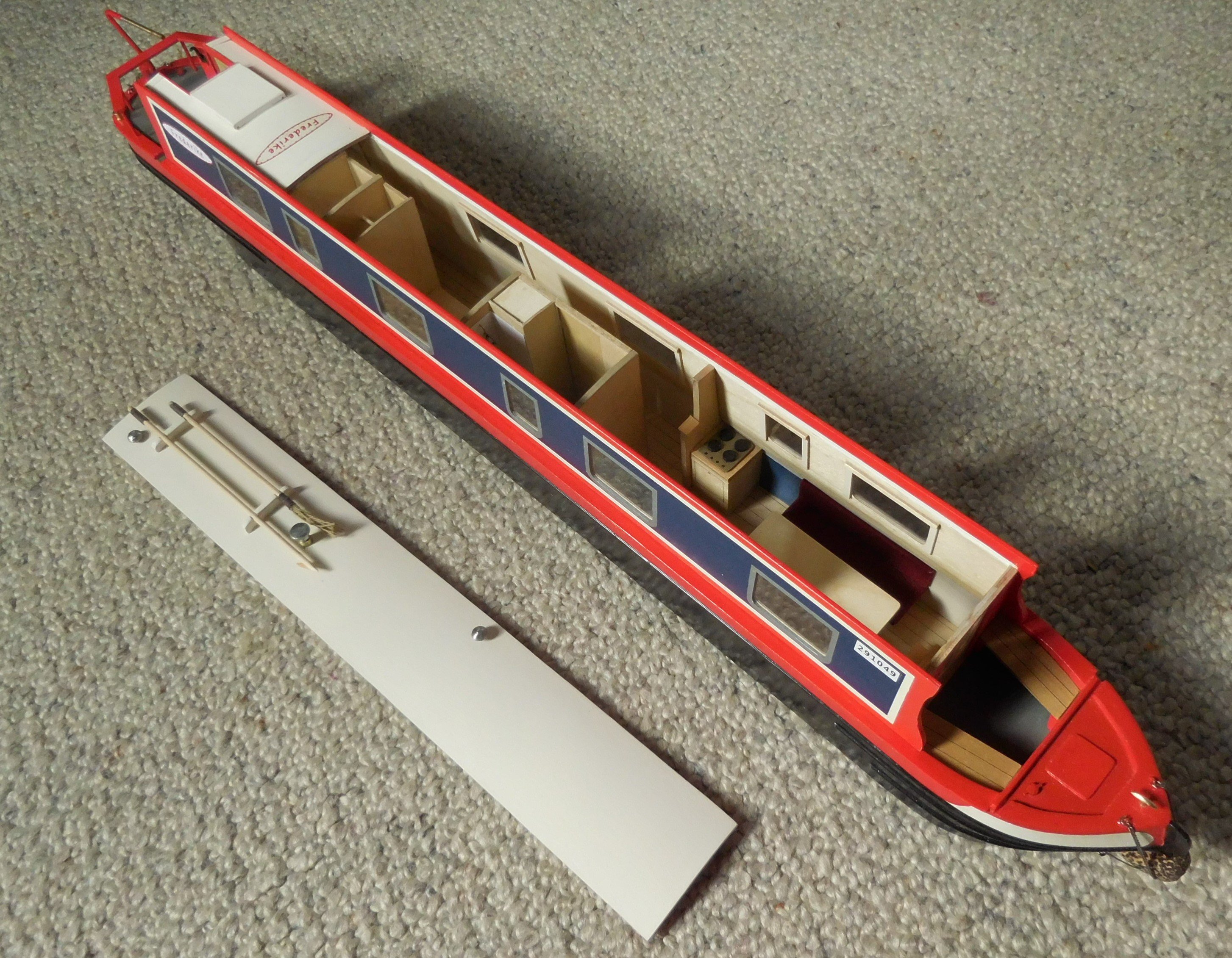
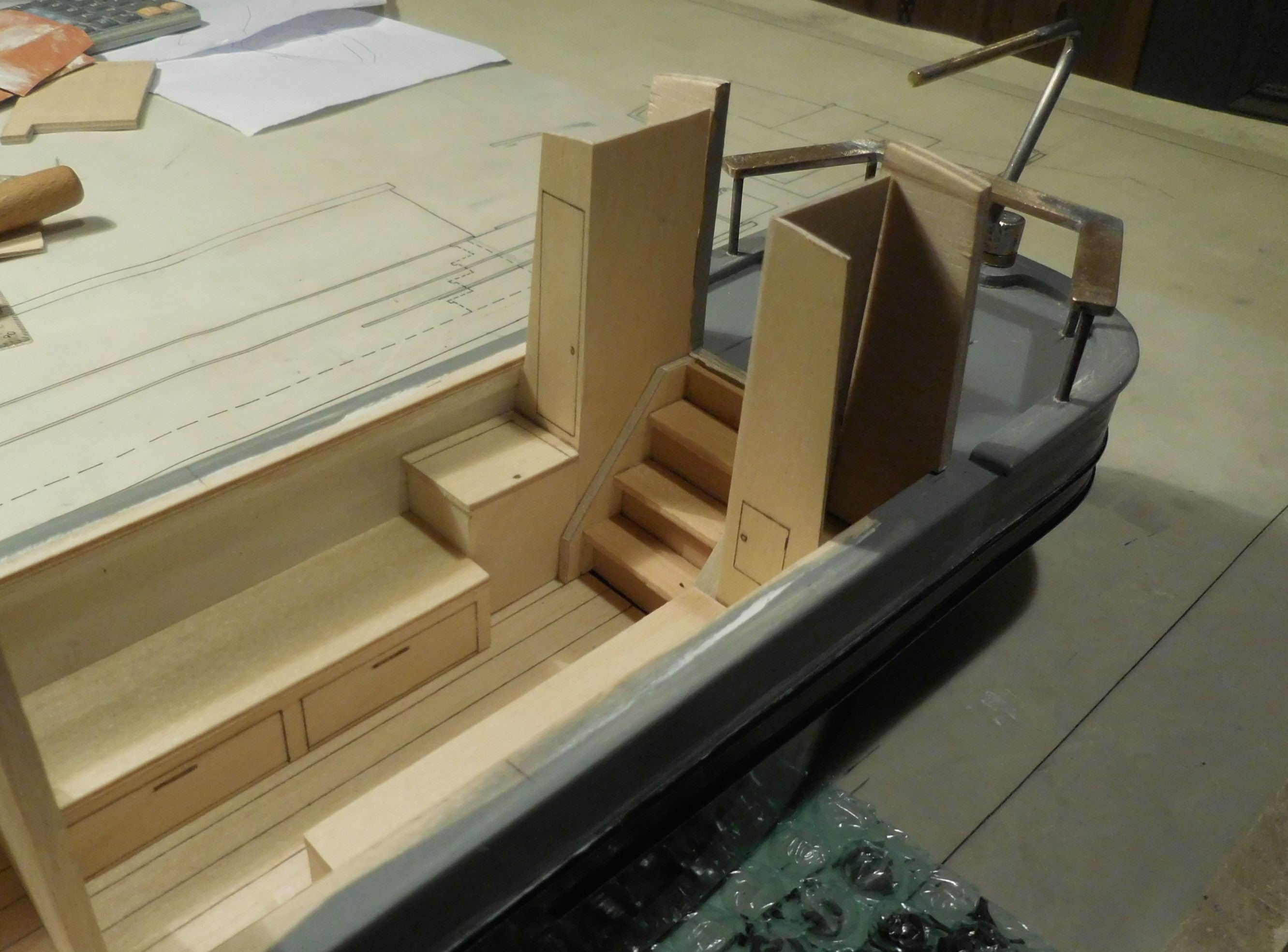
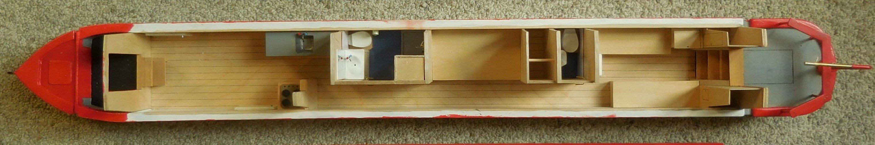
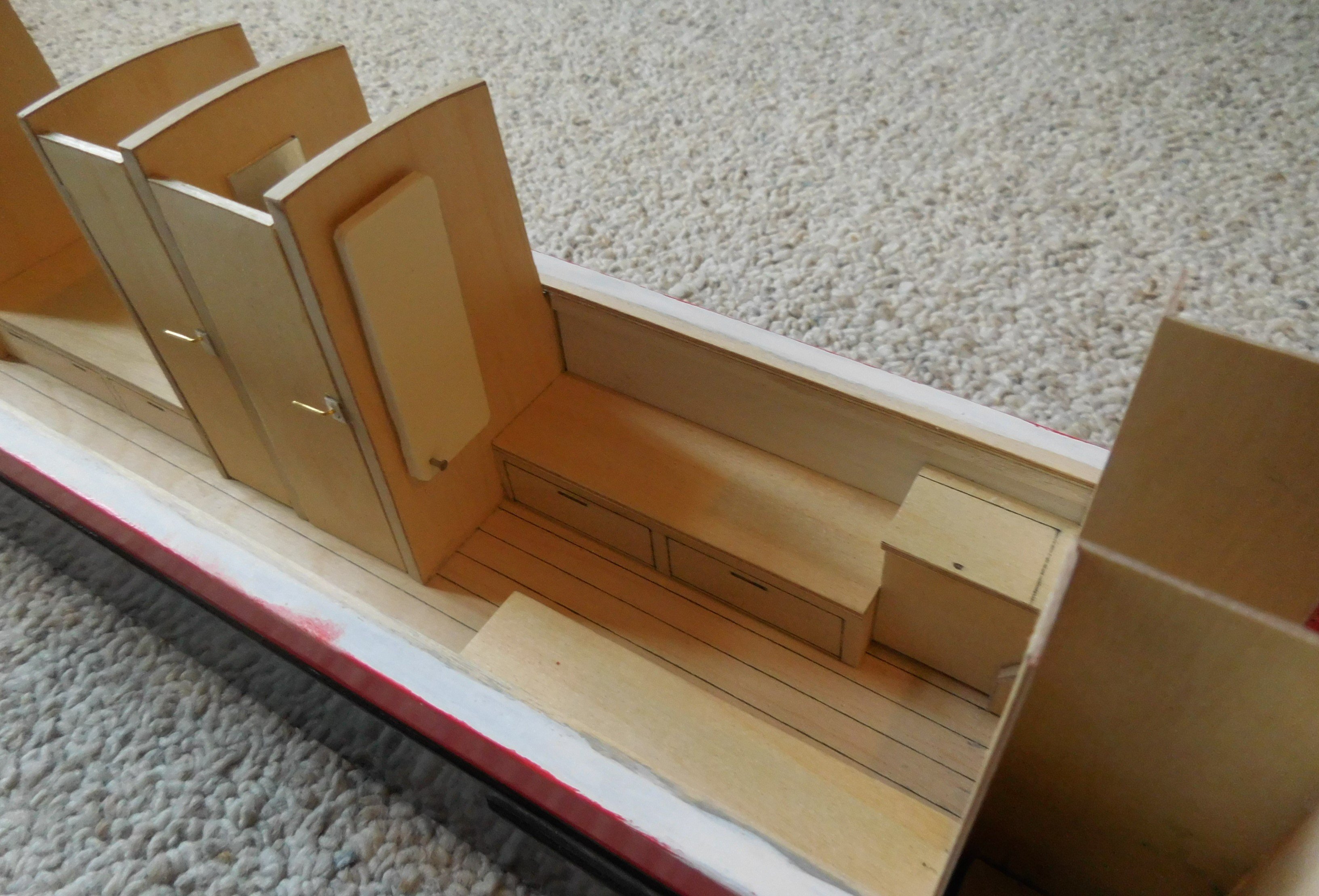
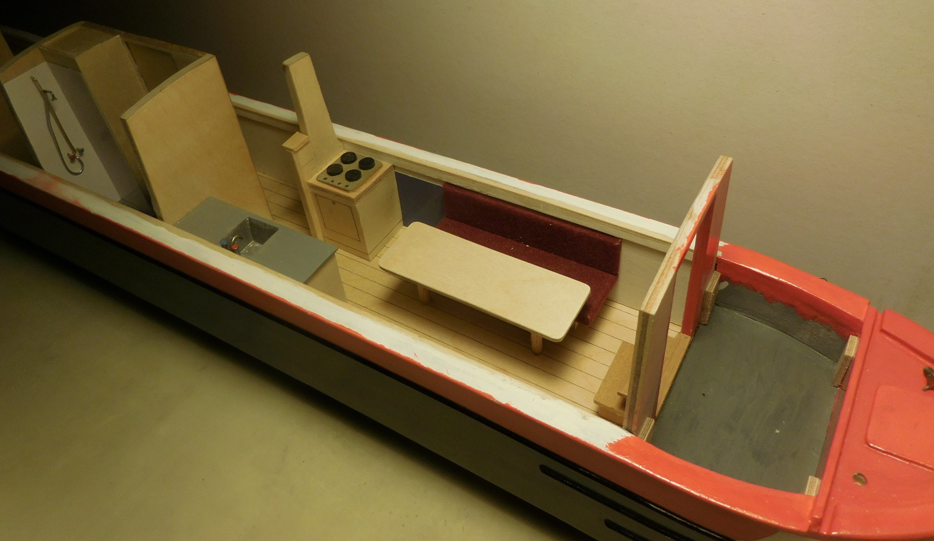
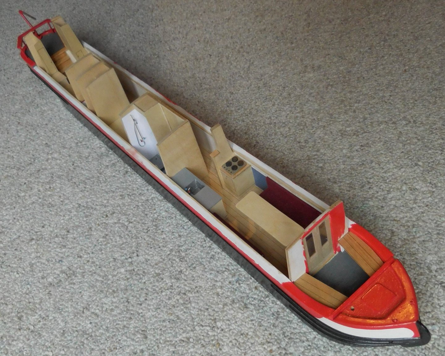
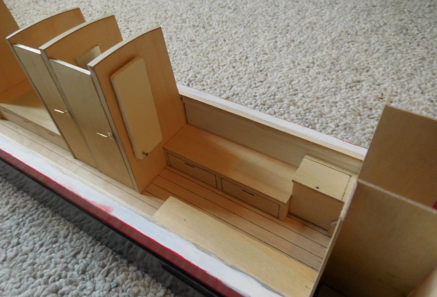
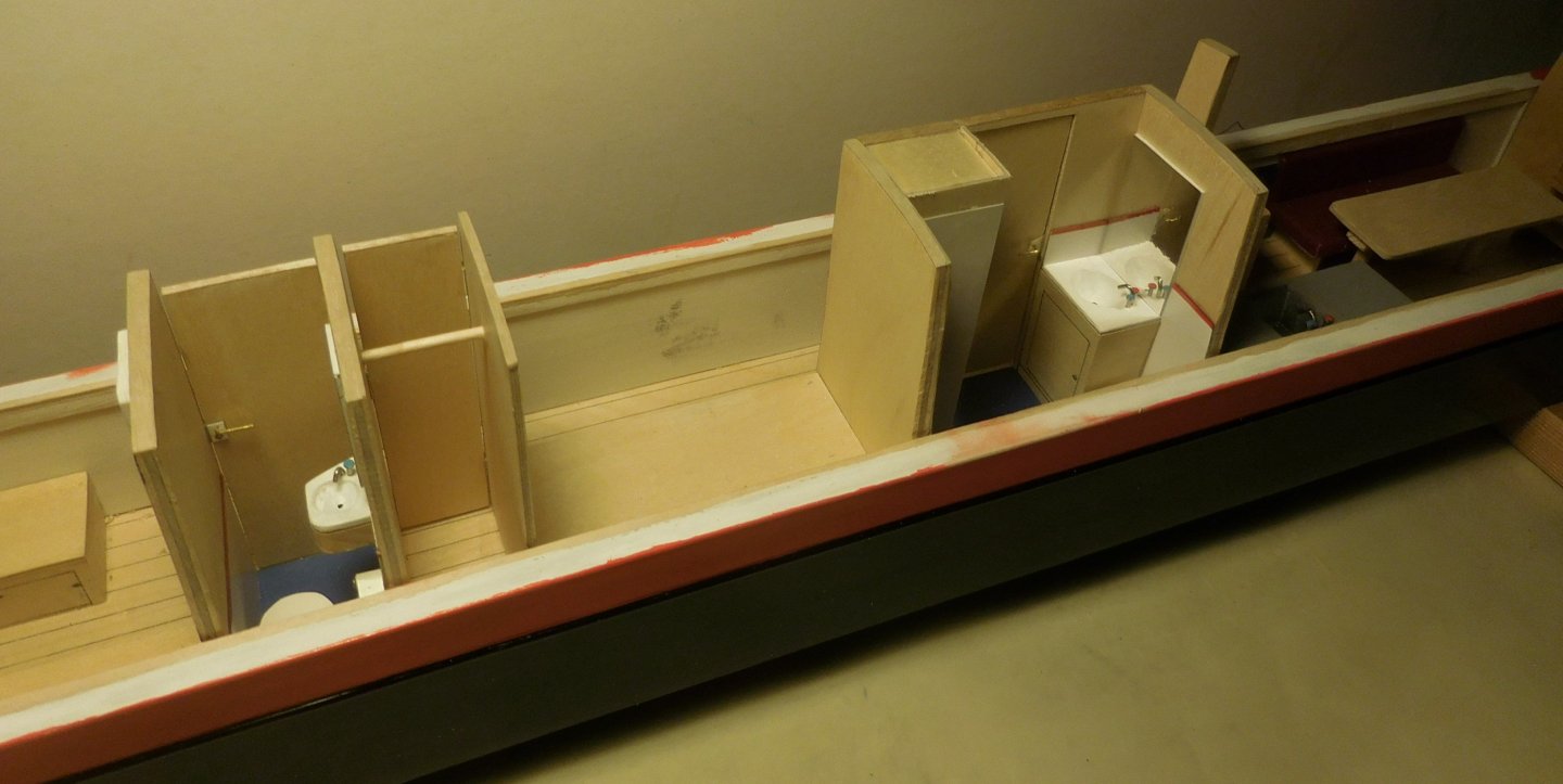
4 The top of the boat must be kept as low as possible to be able to pass under the many low bridges. As a result, there has to be a staircase to get to the bottom of the boat. Here the steps are between two cabinets. On one side is a cupboard for the ship's technology, on the other side is a hanging cupboard. In front of that, two single beds with a narrow passage. Walking from the back to the front, from right to left, the following spaces appear; 1. A toilet with washbasin 2. A hanging cupboard 3. One double bed 4. Toilet/shower/sink and a cupboard 5. Kitchenette with cooking facilities 6. Lounge 7. Stairs to the forecastle One of the panels for the electric heating, here against the side of the toilet. The living room with the kitchen. The table can be lowered so that it becomes a double bed with the sofa. The insides of the toilet, the wardrobe and the shower room. Constant


-
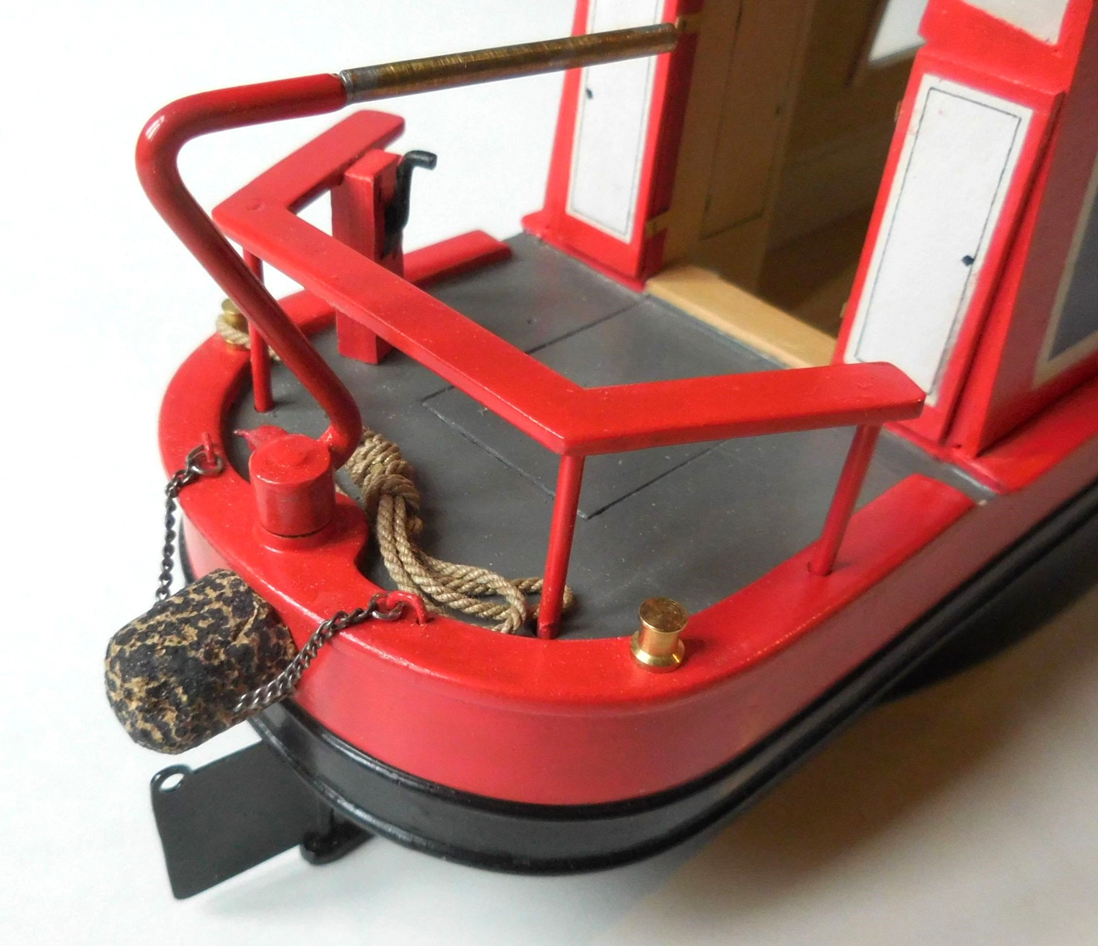
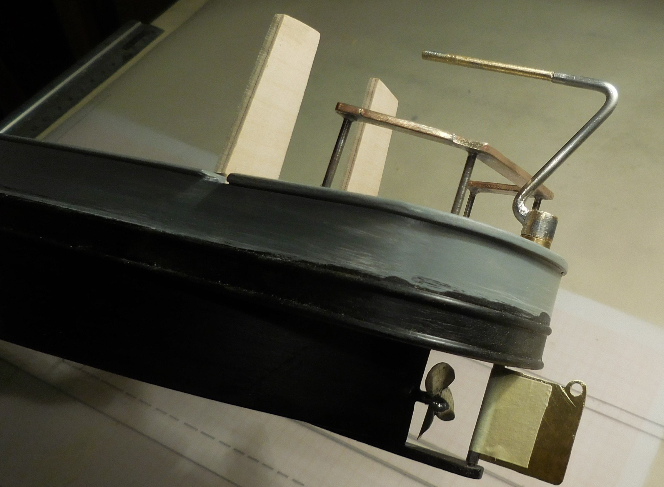
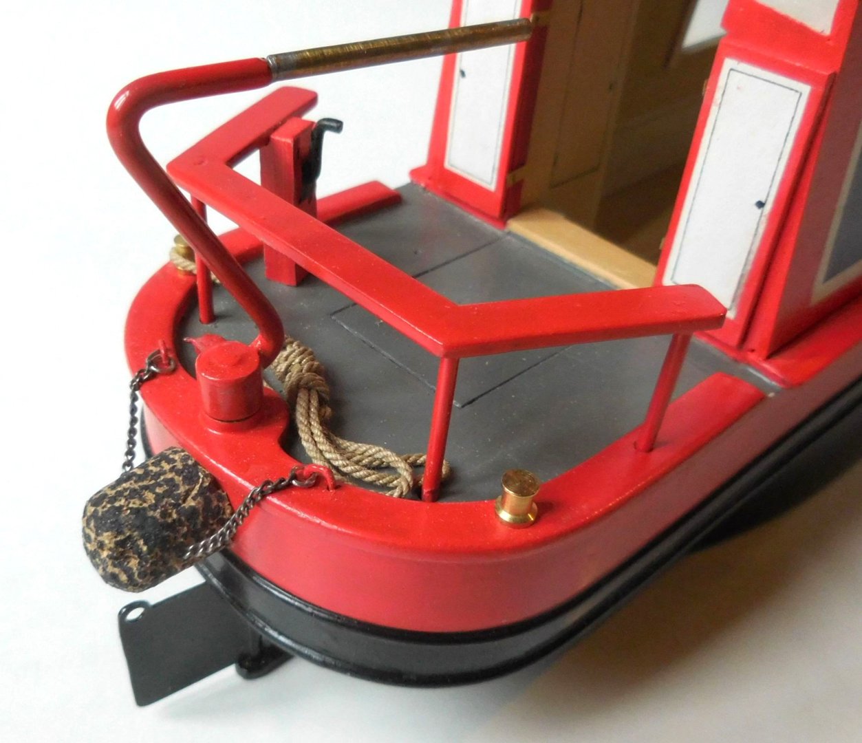
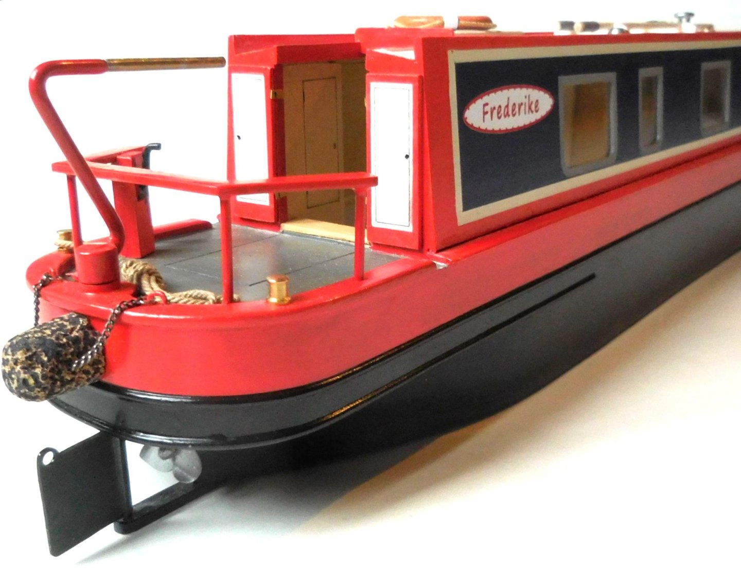
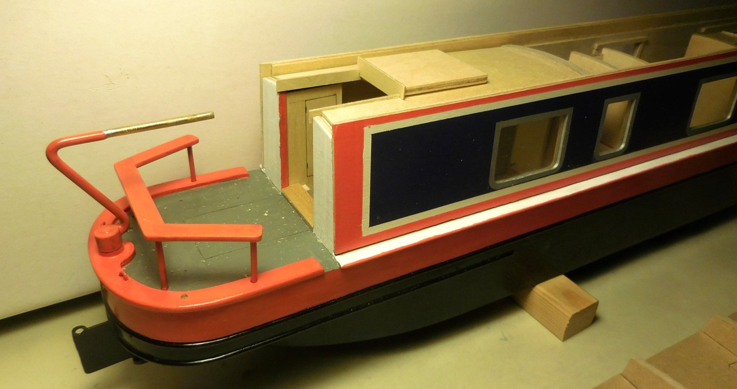
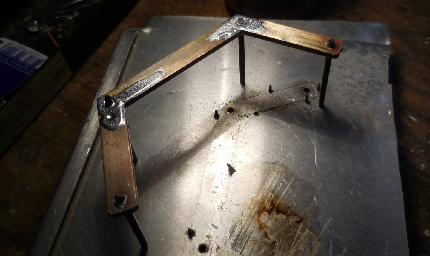
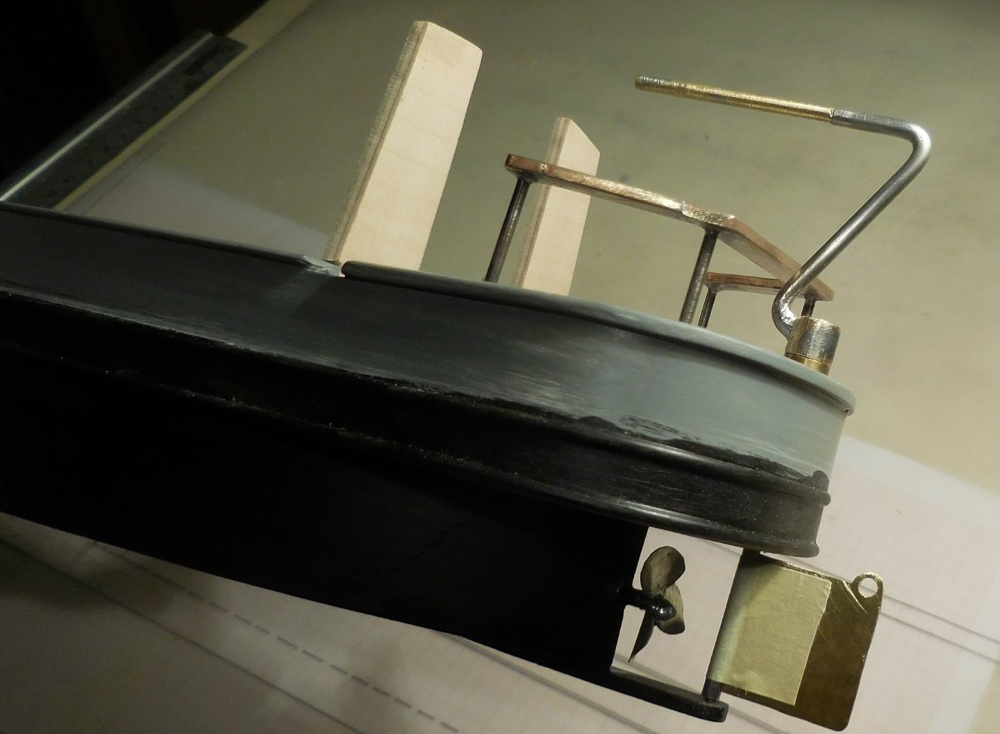
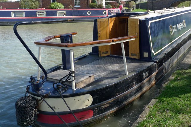
3 At the stern there is always a fence, sometimes equipped with a bench, against which the skipper leans while sailing. This is also where he operates the rudder and levers for the engine. I made this fence out of 2 mm thick brass on which I also soldered the supports. It was then mounted on the aft deck. A hole was drilled through the deck in which a tube was glued in which the rudder pin can turn. The rudder blade and propeller, both soldered to brass, were then mounted. On the model, the tiller can move and the propeller can also rotate in a tube lengthwise of the model. Underneath the propeller is a steel beam that is mandatory in every narrowboat to prevent damage to the thresholds of the locks and the propeller itself. The tiller has a characteristic shape that is the same for every boat. After the hull under the upper bumper had been painted completely silk matt black, work could start on the interior. Constant


.JPG.15e25a20b50ac4697c5857d5bd22b380.JPG)


.JPG.4da94f69eb804f025ba6fad9505da650.JPG)