gak1965
-
Posts
725 -
Joined
-
Last visited
Content Type
Profiles
Forums
Gallery
Events
Everything posted by gak1965
-
 My wife and I were both graduate students there with the relevant crew of friends at JPL. A bit of an aside, I was telling my younger daughter over the weekend how we watched the telemetry coming in live from the 1989 Voyager 2 encounter with Neptune. It was a combination of incredible excitement (the first images from Neptune!) and watching paint dry, because the transmission bit rate was so low it would take a minute or more to do a single line of one image. Still pretty cool. George
- 489 replies
-
- 2
-

-
- minesweeper
- Cape
- (and 1 more)
-
Yep. I lived in LA 9 years in the mid 80s to the late 90s. It was much better then, but because the inshore breeze keeps LA (but not the San Gabriel Valley where we lived) cool, it also pushes all the smog up against the mountains so that they become hard to see. My first day in Pasadena, I was told that there the San Gabriel Mountains were only 5 miles away, and yet I couldn't see them. On better days (and especially after a rain, or when the Santa Ana winds come off the desert, the view from the airport is unbelievable.
- 489 replies
-
- 2
-
-
- minesweeper
- Cape
- (and 1 more)
-
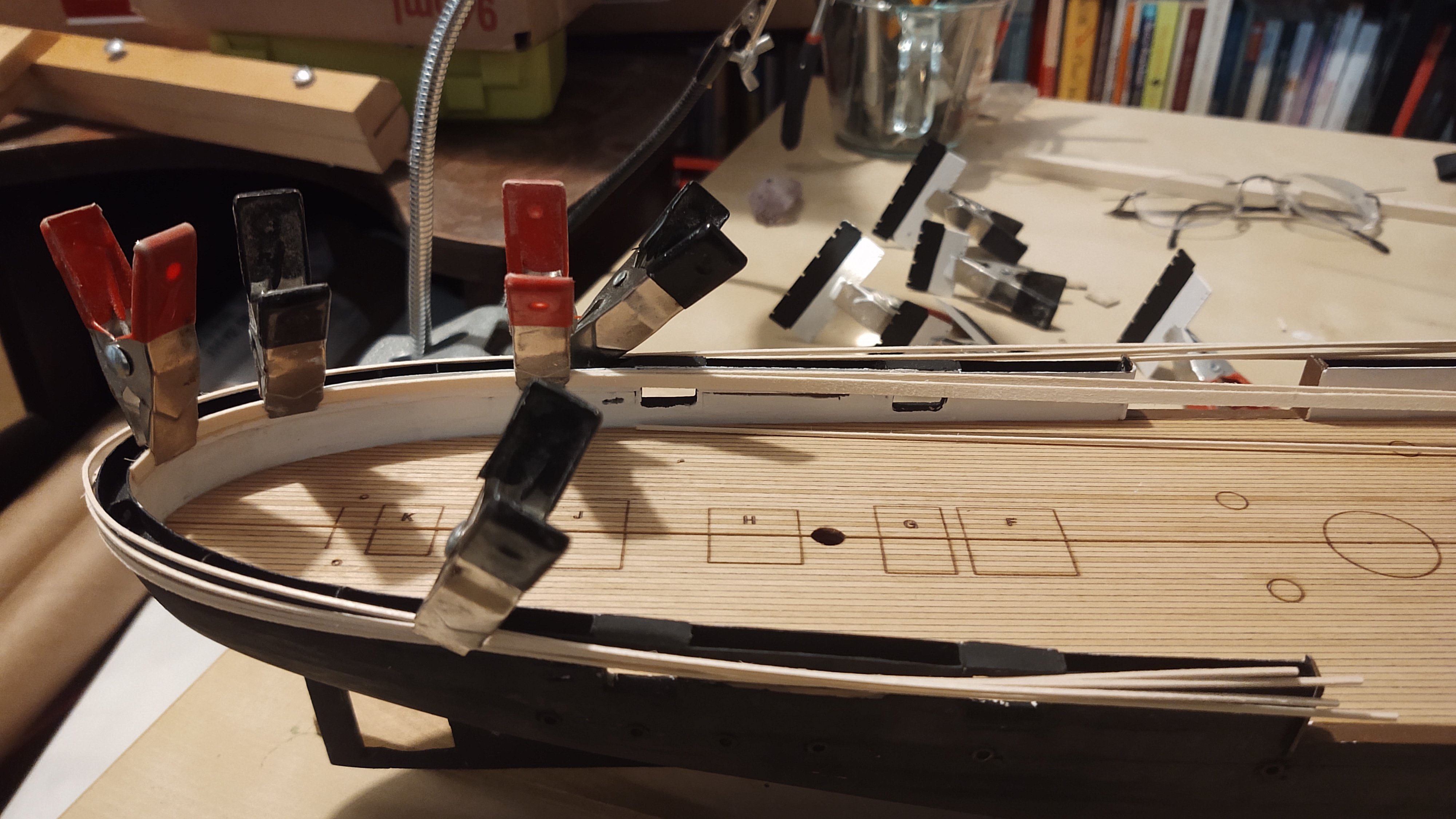
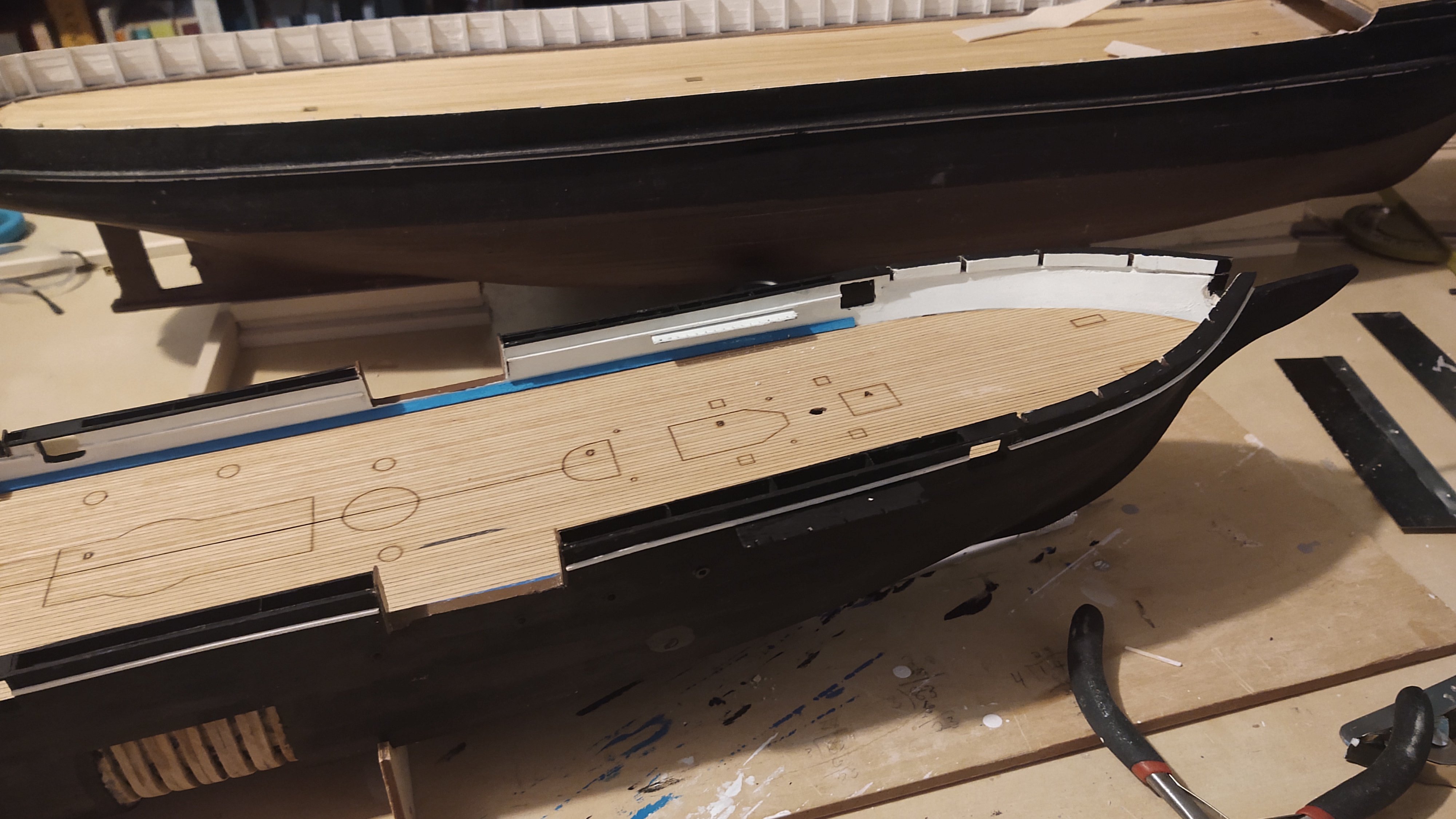
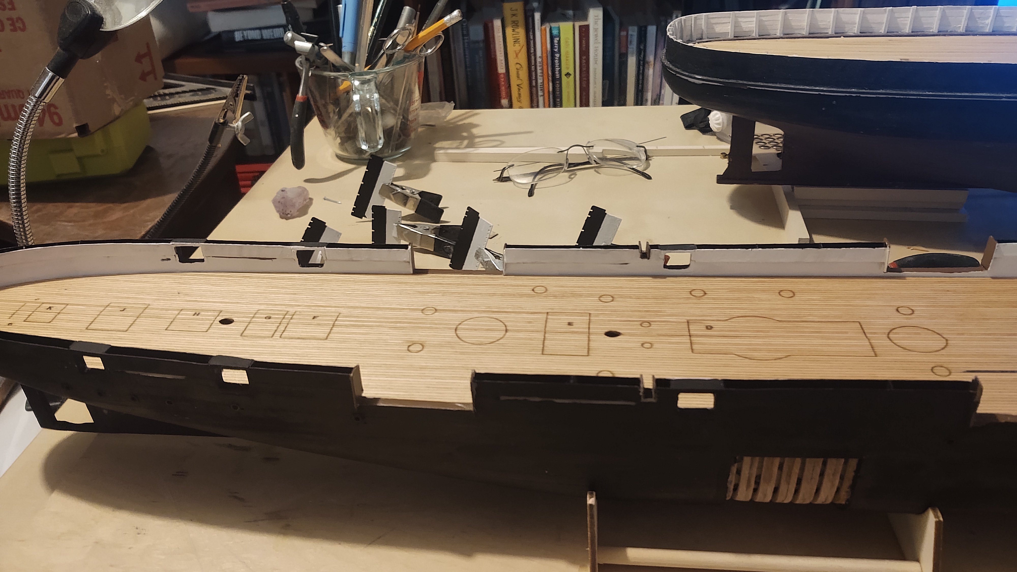
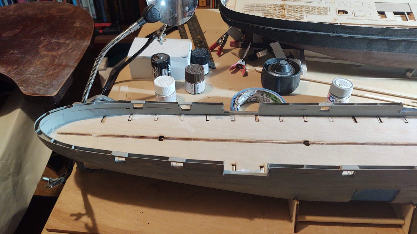
An update on the Kearsarge. The next step was to put the trim (black and white) on the hammock netting. On both the inside and the outside it is black on top and white on the bottom of the nets. Because the aft of the ship has a fairly sharp curve, I soaked the 1/32 square stock, fitted it around the curve, and let it dry. While I was at it, I soaked the basswood that was going to become the waterway and clamped it in place until it dried. In the photo below, the trim for the hammock nets is outside, and the waterway is inside (the deck is not yet tacked down). Once dry, I painted half of the trim black, and the other half white, and then painted the waterway blue. I mounted the trim to the hammock netting, and once the black (upper) trim was in place, I also touched up the black paint at the top. Next, I attached the deck, and then fitted the waterway in place. In the photos below, I have temporarily fitted the pieces that produce the channels and the pinrails. Here is the ship from a couple of angles. First the whole ship (with the 1:72 Discovery in the background. The forward half of the ship. As you can see there is a visible gap that is retained, but that is where the tracks for the guns will sit, and I will probably align the gun to cover it up. There is also a small issue between the deckhouses in the stern, but as described, a bit of rope or other item will no doubt cover that up. Anyways, thanks for looking in, and a Happy St. Patrick's Day to those that partake! I will probably set this aside for a little while and do some work on the Discovery for a little while. If I do work on it, it'll probably be to put the copper plating on. Regards, George


-
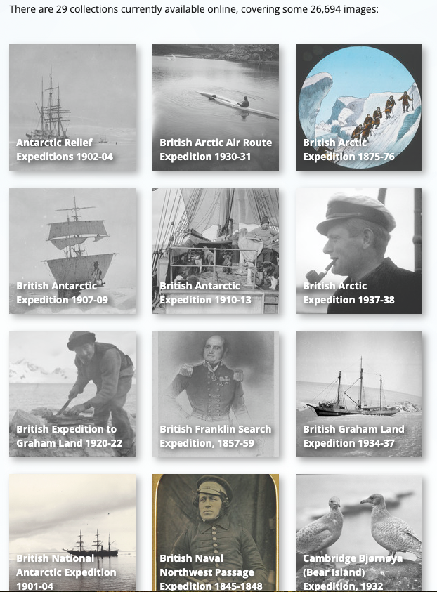
Appreciate it guys. FWIW, my younger daughter kept telling me that if this potential employer had been a man, I wouldn't want her dating him! So, probably for the best. The Scott Polar Research Institute was quite cool. They operate a small museum, library, and picture library, and obviously support research. They were extremely accommodating - all I had to do was sign up for a study desk in the picture library, and they brought me whatever I asked for. The URL for the institute is here: https://www.spri.cam.ac.uk/. They cover a whole range of expeditions, not just Scott's, and they have a nice (if incomplete) online picture catalog. Great people all around. Regards, George
-
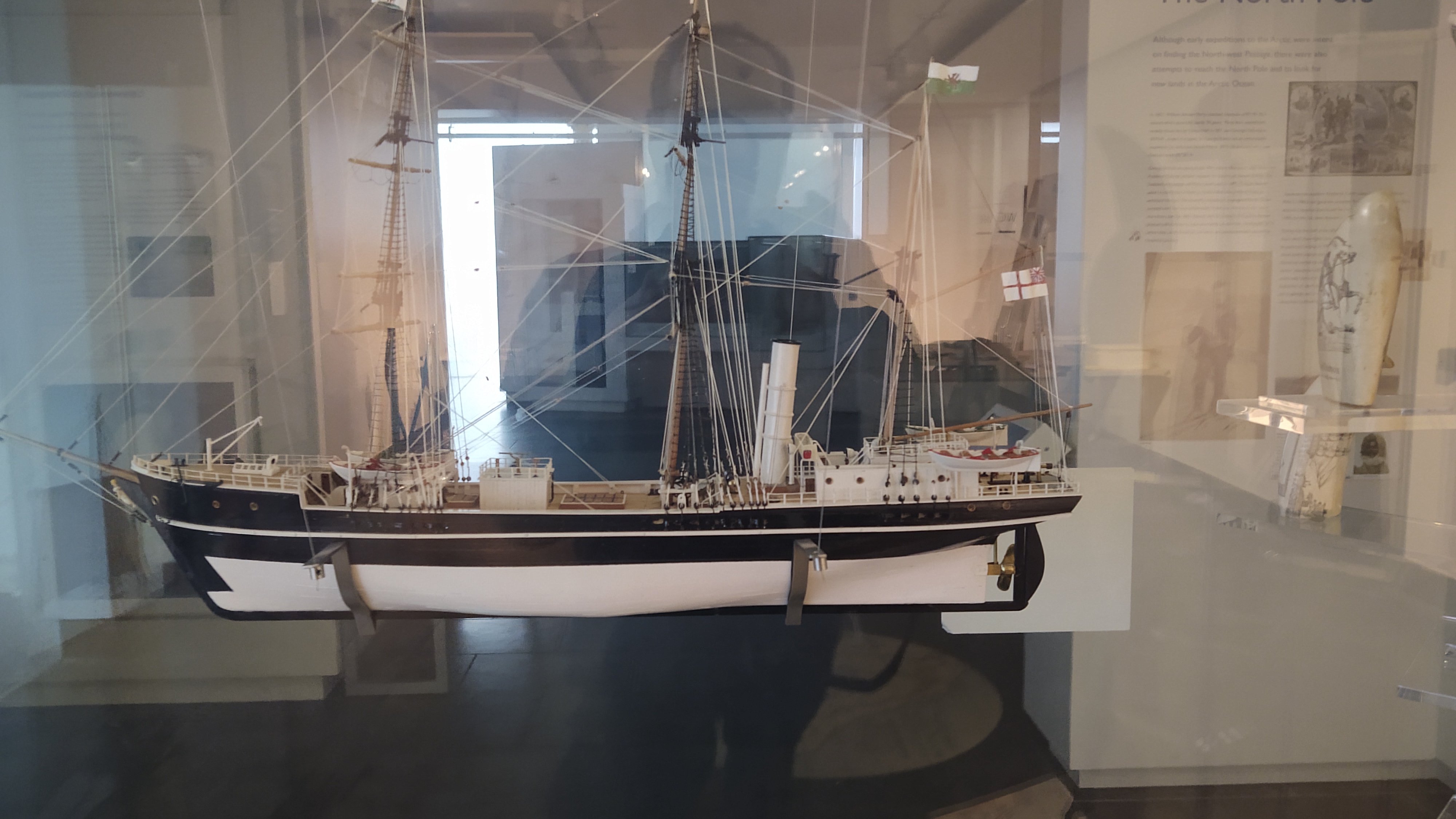
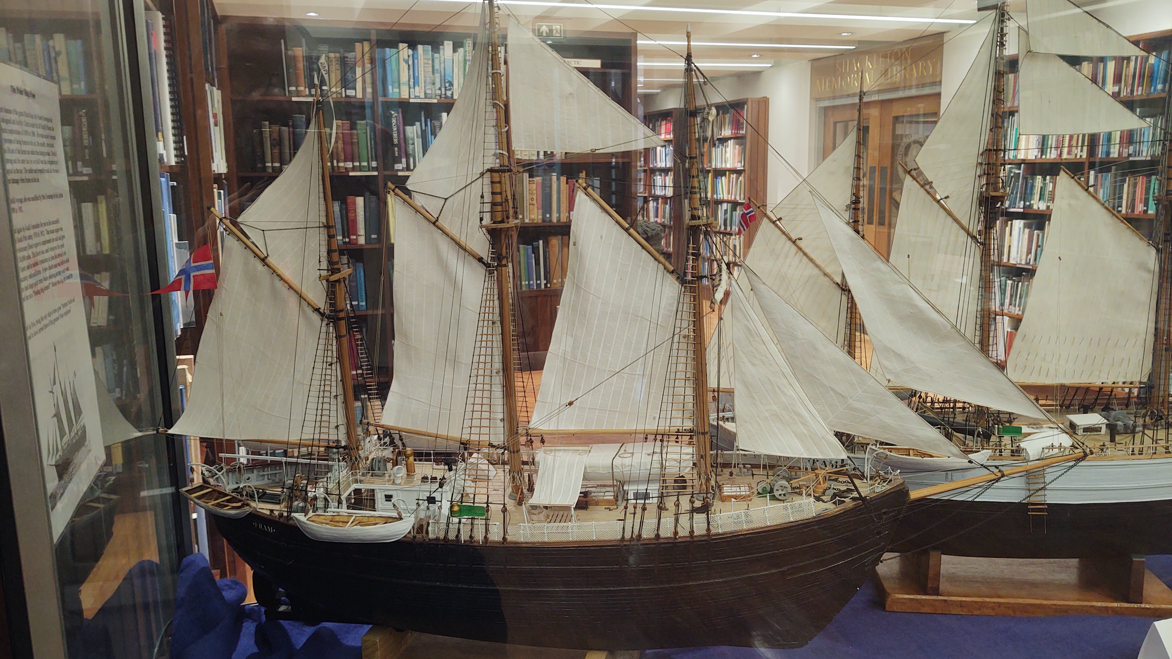
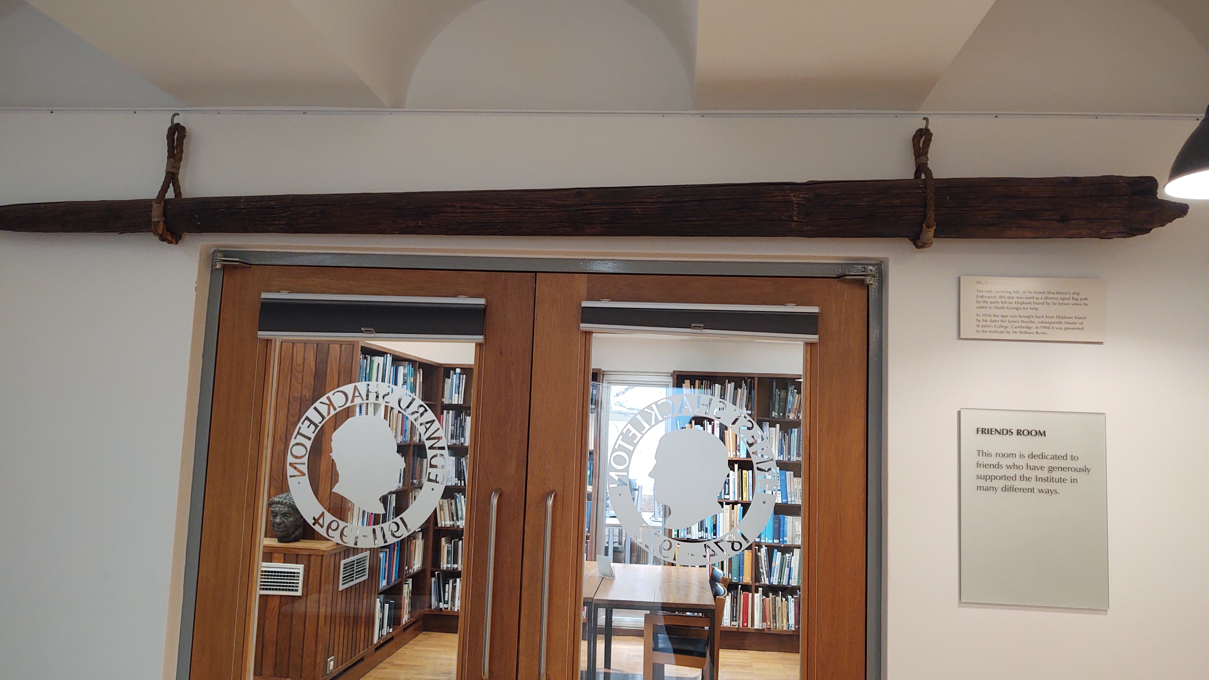
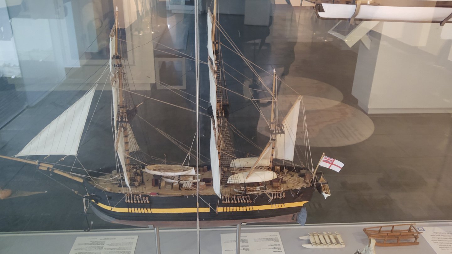
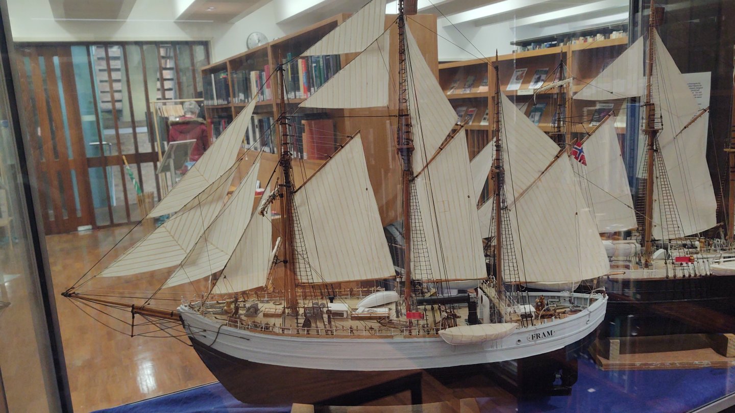
Well, I am back from the UK. 9 hours of interviews in Manchester (Thursday), 8 hours of interviews in Oxford (Friday), and then a panel in London (Tuesday). I returned Tuesday night to another 3 hours of interviews for something else Wednesday morning - most of us are generally best jet lagged out of our minds. Alas, I will not be moving to the UK, I found out the day after that they had decided on someone else (I was one of 4 at that point). I wasn't overly surprised, but rather than contacting me directly, they went through the search firm to tell me. Okay. With that said, on Monday, I did one of the coolest (ha ha!) things I've even done. I went to the Scott Polar Research Institute in Cambridge, and they let me look at the ORIGINAL photo albums from the 1901-1904 British Antarctic Expedition. I couldn't take photos, but I got 2.5 pages of notes on details about the ship. The facility also had some pretty cool artifacts. A model of the Roald Amundsen: Here is a model of the Fram. The Erebus: The Terra Nova: Tagging @Tomculb who is working on Endurance, this is the only piece of the ship that made it home: Like I said, very cool. Getting back to work on the ship this weekend. Regards, George


-
Rick, This isn't necessarily correct but here's where I put the davits so between the 3rd and 4th mizzen shroud (counting fore to aft) and just aft of the main chainplates. I found that running the davit lines was complicated, but I was able to do so without interference if I was careful. The build log entry is here: The boats are looking great! GAK
- 359 replies
-
- 1
-
-
- Flying Fish
- Model Shipways
- (and 1 more)
-
A bit of an update. Outer hull is painted black, ready for the coppering. Inner bulwarks are painted white. I realized I hadn't cut out the sally ports, so I did that. I stuck a piece of 3/16 wood in the hammock netting to stabilize it while I made the cut, and the put brown painted hammock net ends in place. I spent some time finishing the deck and trimming it to size. Here are some photos (not tacked down). The combination of the stain and the suggestions from Tim and Nic removed most of the apparent gap. Once it's tacked down it will be even less obvious. No more for at least a week as I am I. The UK for a job interview in Manchester, Oxford, and London and won't return until next Tuesday. Thanks for looking in. Regards, George


-
Hm. I assume that the wrapping isn't transparent? Might have been interesting to look at the structure, but perhaps not ideal. FWIW, the last few times I've been in Boston (which tended to correspond to move in/move out dates where my kids where in college), the Constitution was similarly or at least partially dismasted. Yep - I've visited the Cutty Sark (and the NMM and the Royal Observatory) in her current (post fire) state. I was really impressed with how well they have her displayed, and it was very cool to walk under the keel. I thought about it. The interviews are in Manchester, then Oxford, then London. I will have a bit of time the day before the Manchester interview and depending on a bunch of imponderables (where the hotel I'm being put up is relative to the airport and train station, I might be able to take the Transpenine express to Edinburgh and then Scotrail. My concern is that I absolutely have to be at the interview site in Manchester at 9:30 AM the next day and I don't like being dependent on trains like that. I hadn't thought about a plane. London to Dundee seems to about the same distance is Washington DC to Boston, and I've certainly taken day business trips to Boston. I need to think about that. The main reasons I had kinda decided to do something else was because (a) I wanted to be within driving distance and (b) because the ship in Dundee isn't really the ship I'm modeling. Discovery was heavily modified in 1923. The only thing above the main deck that is the same is the engine enclosure. All of the rest of the deck furniture was changed, the masts moved and switched to a different rig (from 4 to 5 yards on the fore and main). It would be cool to see, but the time factors (4 hours sitting in airports + 3 hours airborne + 3 hours in hire cars) - I dunno. If the job offer comes through and I take it there will be lots of time to visit Dundee. Maybe Bristol|Bath|Brunel this trip - though I'm sure the thought will be in back of mind for the next couple of weeks... Regards, George
-
No update on the ship per se (I've been doing some work on Kearsarge for a little while. However, in 2.5 weeks I'm hopping over the pond for some job interviews in the UK, and I have a Monday off. Which begs the question, what to do? As it happens the Scott Polar Research Institute at Cambridge University has the originals of many of the photographs from the 1901 Discovery Expedition, and I have booked a desk in the photo library so that I can see the originals and resolve some of the questions that I was unable to answer from the resolution of the scans of the pictures. Very exciting! Regards, George PS: I may also have a chance to pop down to Portsmouth to see HMS Victory, HMS Warrior and the Mary Rose or over to Bristol to see the SS Great Britain (and Brunel's great Clifton Suspension Bridge). Choices, choices, choices.
-
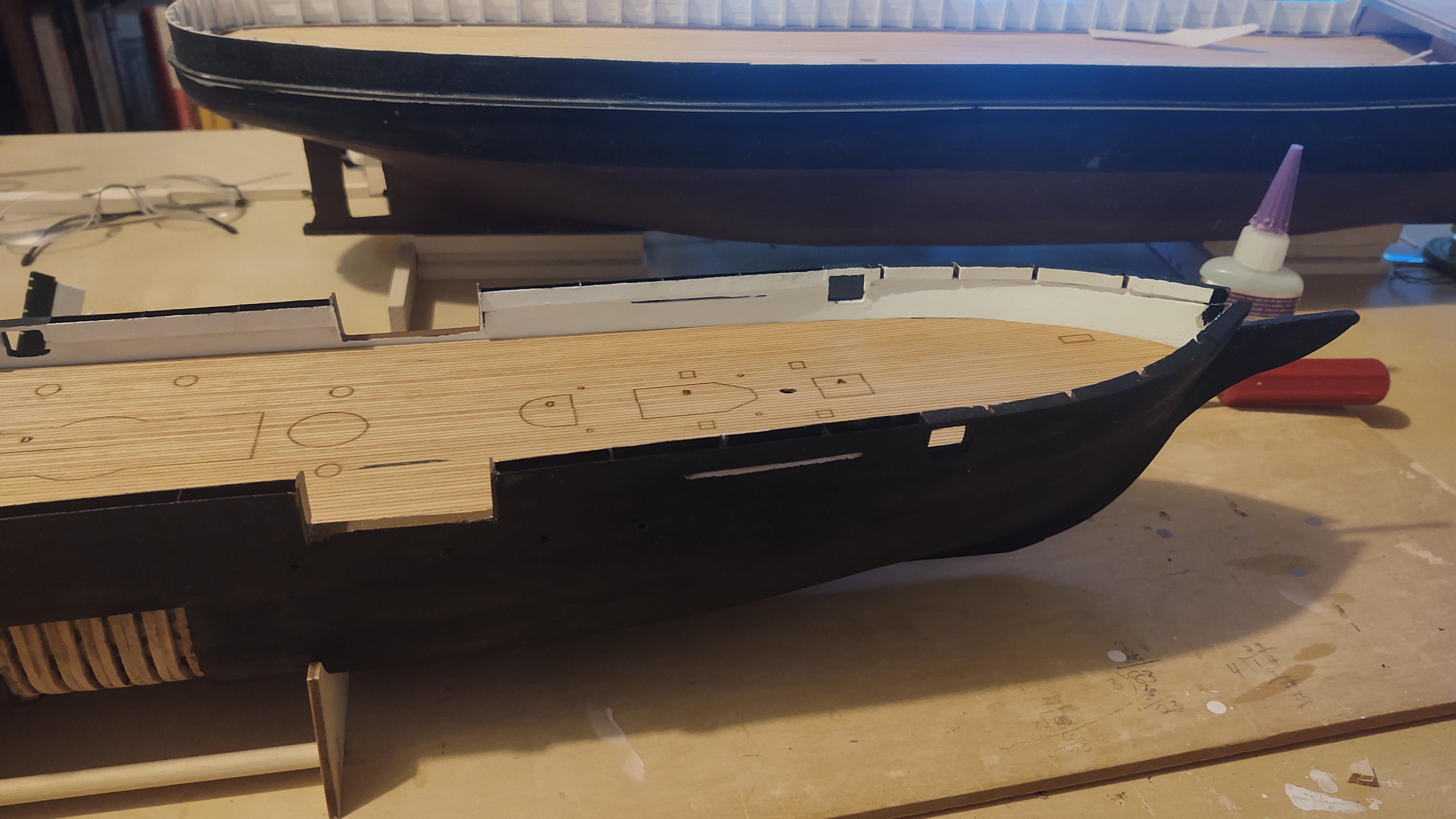
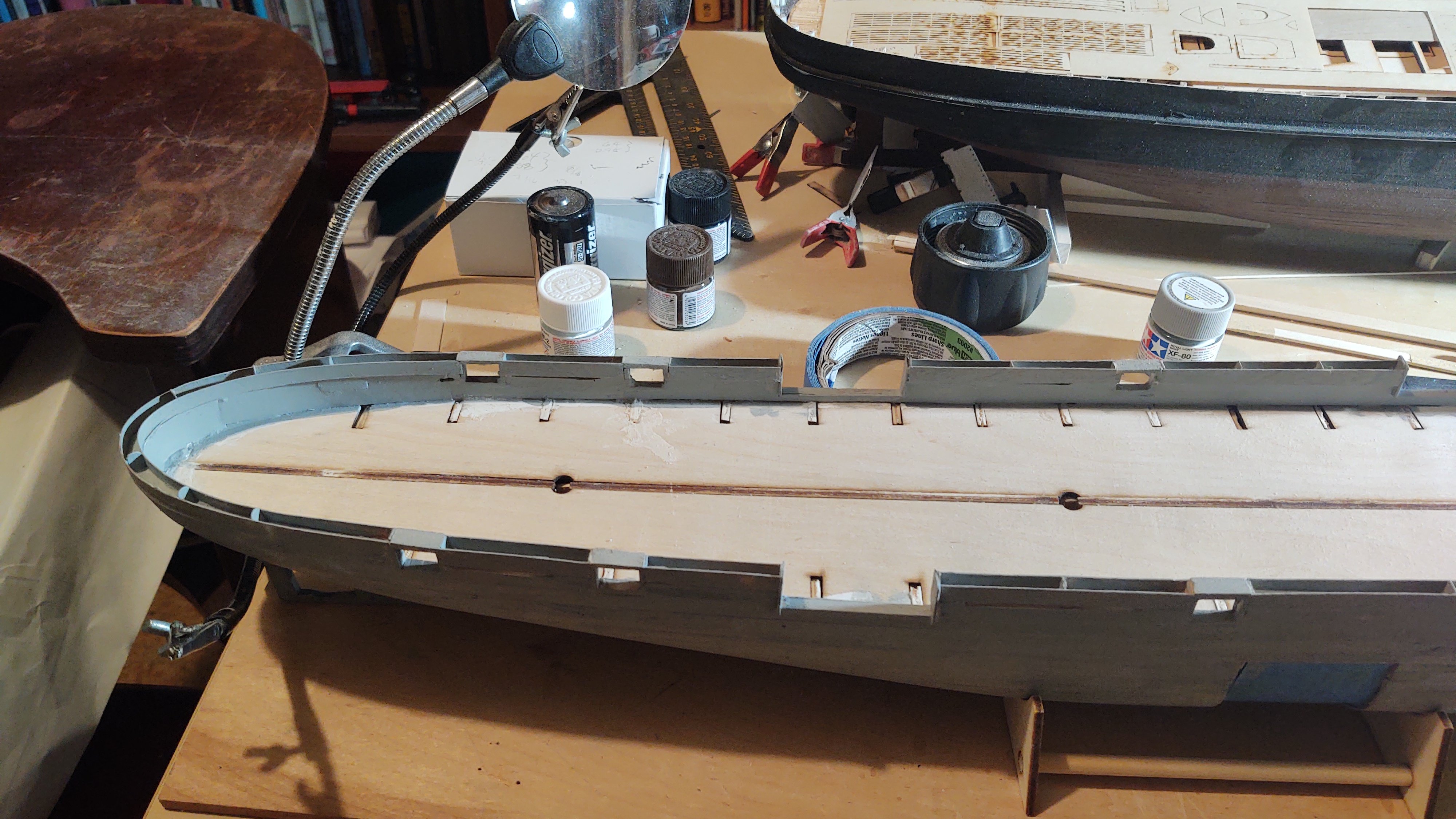
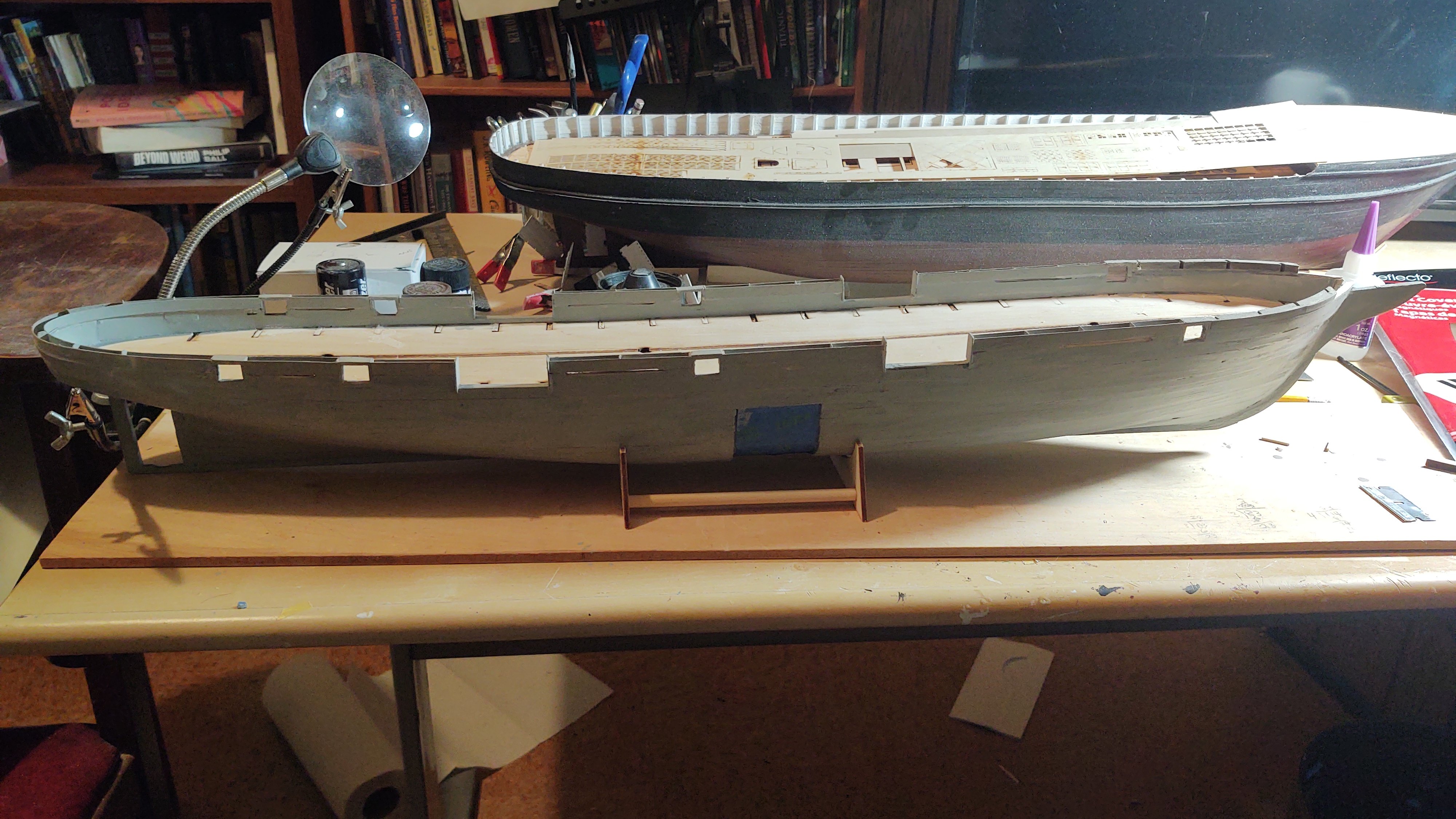
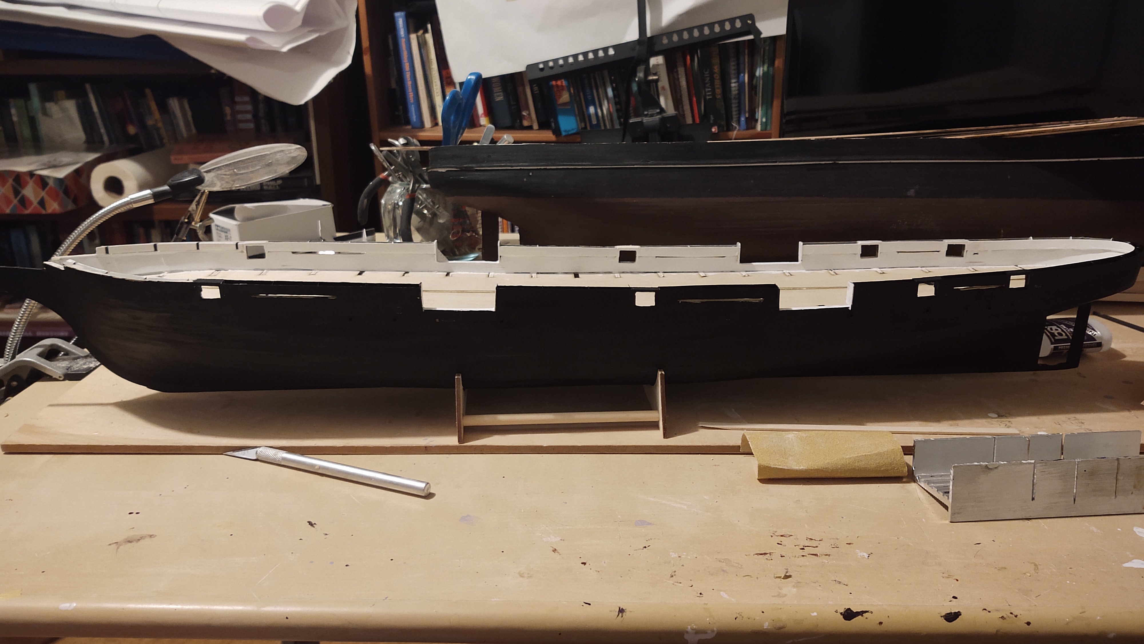
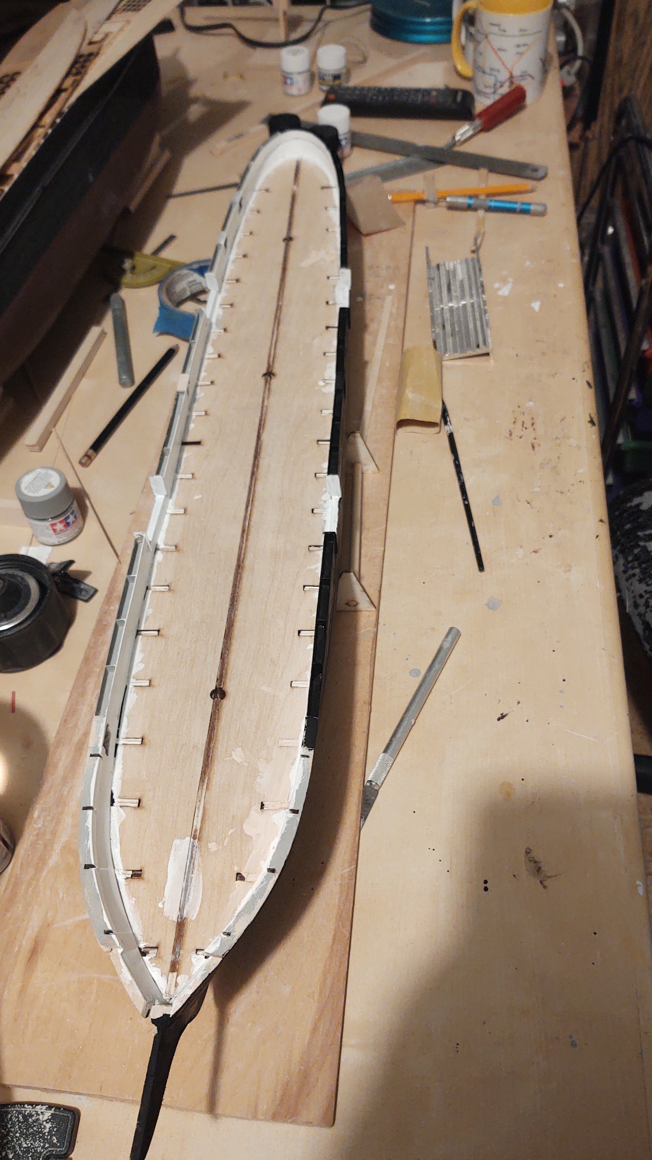
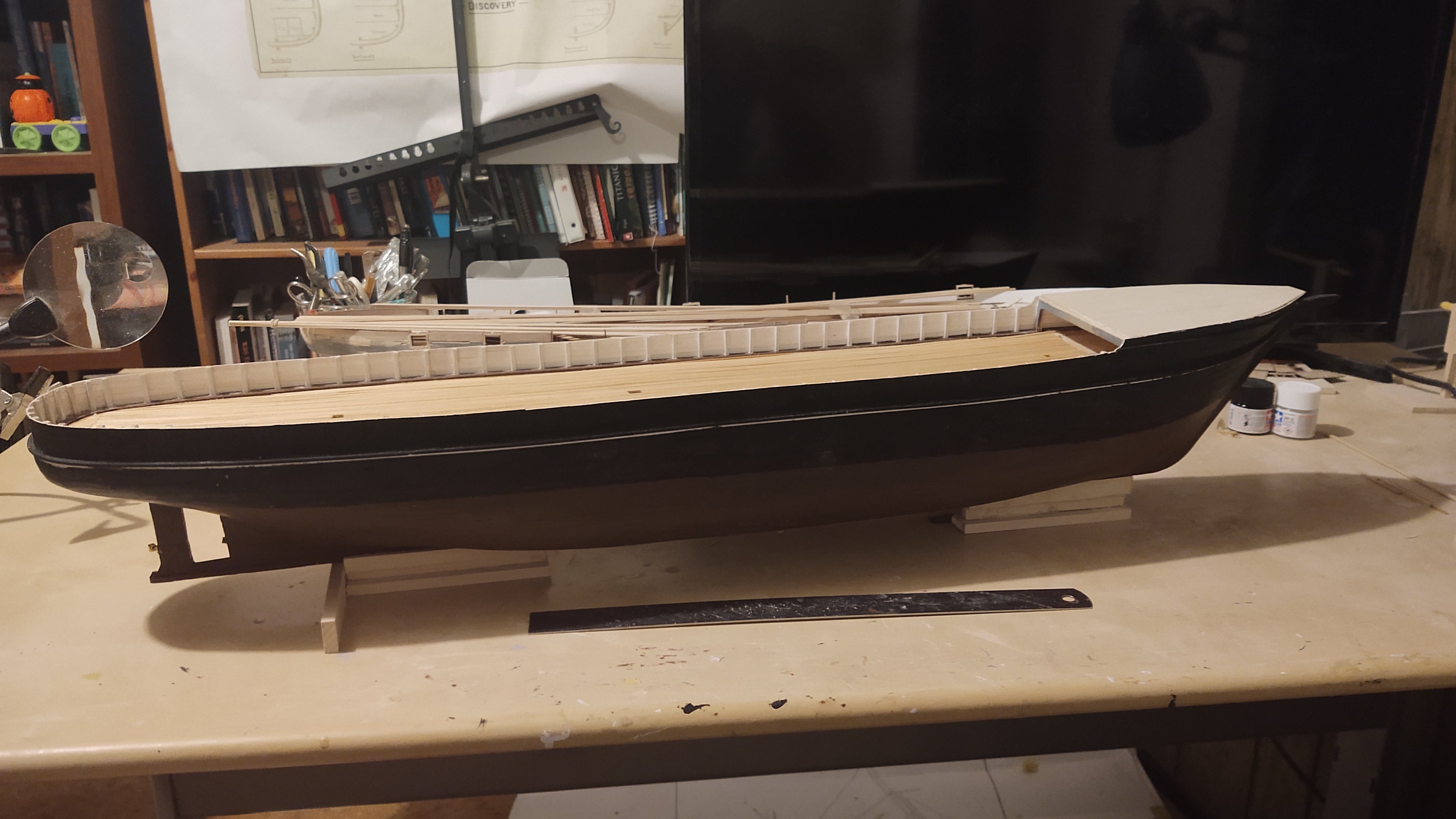
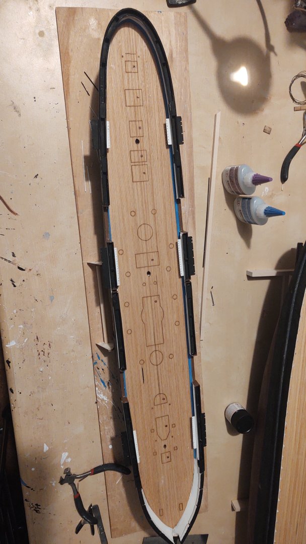
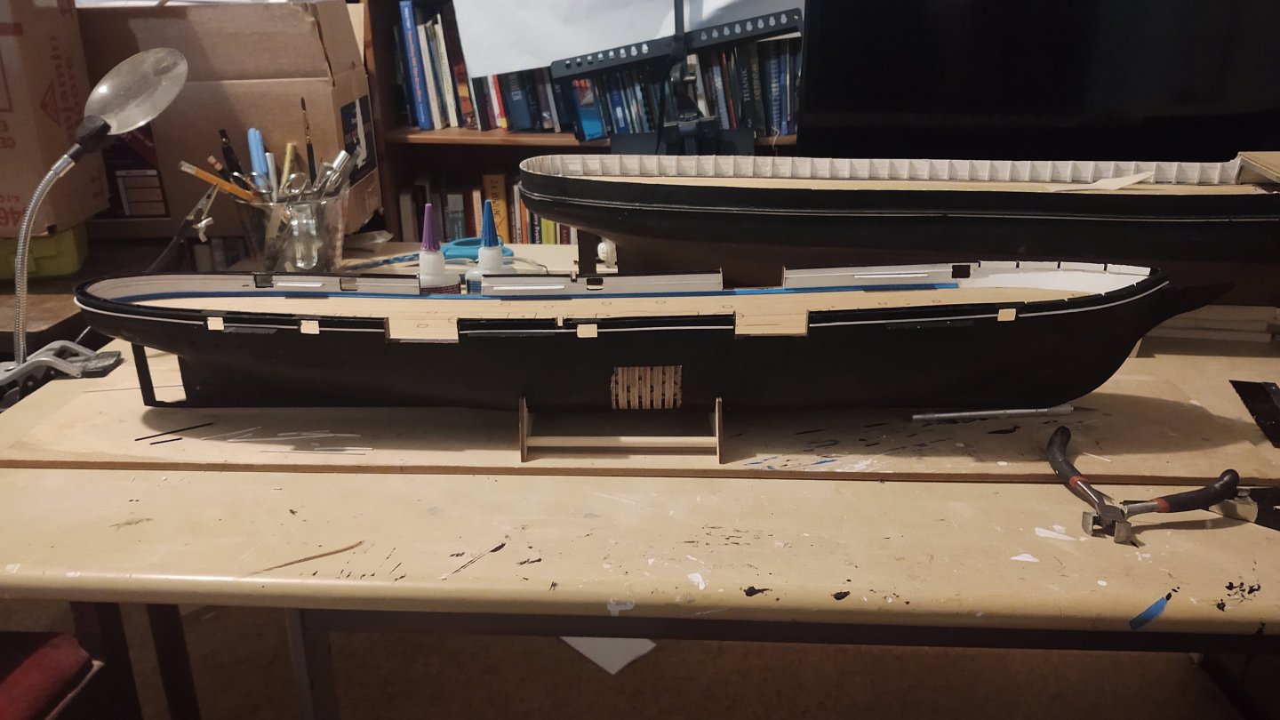
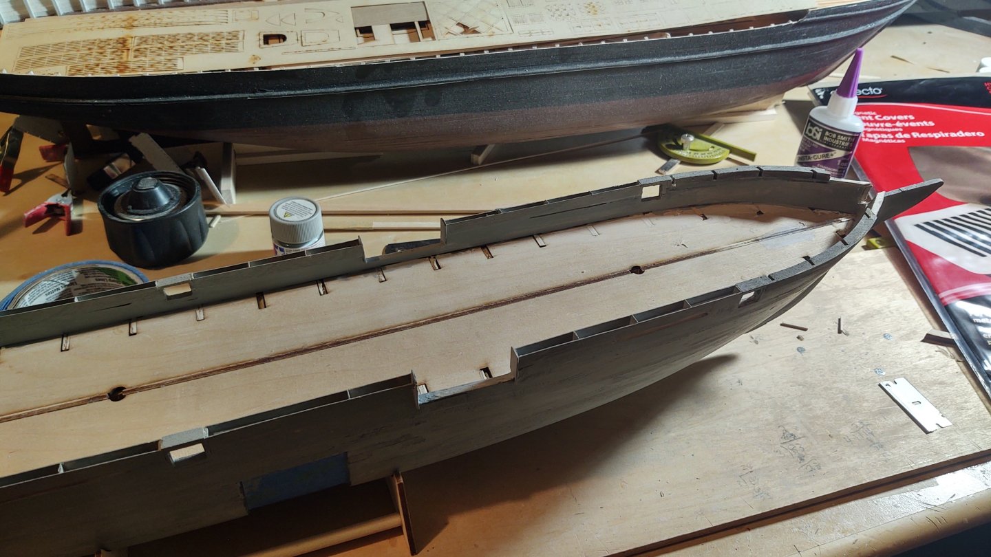
Another update with some real progress, I think. First, I completed the hammock netting around the ship and fixed the frames for the gunports. I also mounted the laser cut pieces that provide the support for the forecastle deck. The top of those pieces need to be level with the top of the gunport frame, and as built, that was not the case, so I put the bow down on a piece of paper, traced the exterior from the forward gunports to the prow, and cut out four thin pieces of wood that I could use to build up the area under the deck. They were mounted and then sanded until they were (a) consistent with the outside curvature of the hull (b) properly level against the gunport, and (c) even at the prow. Took some time but it worked. Here are a couple of photos after an initial sanding and some primer. After this, I painted the interior bulwarks white (took 3 coats), and then installed the portholes (there are 20 of them): I've started painting the hull. This is the port side, painted black on the outside. and a view of port side from the bow. The starboard side isn't done yet, I wanted it to dry a bit before I turned it on its side. I am going to apply copper tape sheathing as I did with the Flying Fish, but I like to apply the copper to a black rather than primer, gray or unfinished bottom - I think that any gaps look better. As you can see between this ship and the Discovery in the background I've been going through a lot of flat black and flat white paint lately! As @MrBlueJacket says, "putty and paint makes it look what it ain't". I do have one question to those looking in. This is first time I've used a scribed deck, and I'm concerned that the line where the two halves join is going to be obvious. Here is a photo from while I was fitting the deck halves: As you can see, it looks good forward (where it will mostly be hidden alas, and is more obvious aft. I sanded off the char (holding the halves together so they would be uniform) and that helped, but... I haven't put any kind of stain on it yet, does that help? Any advice would be appreciated. Thanks for looking in! George


-
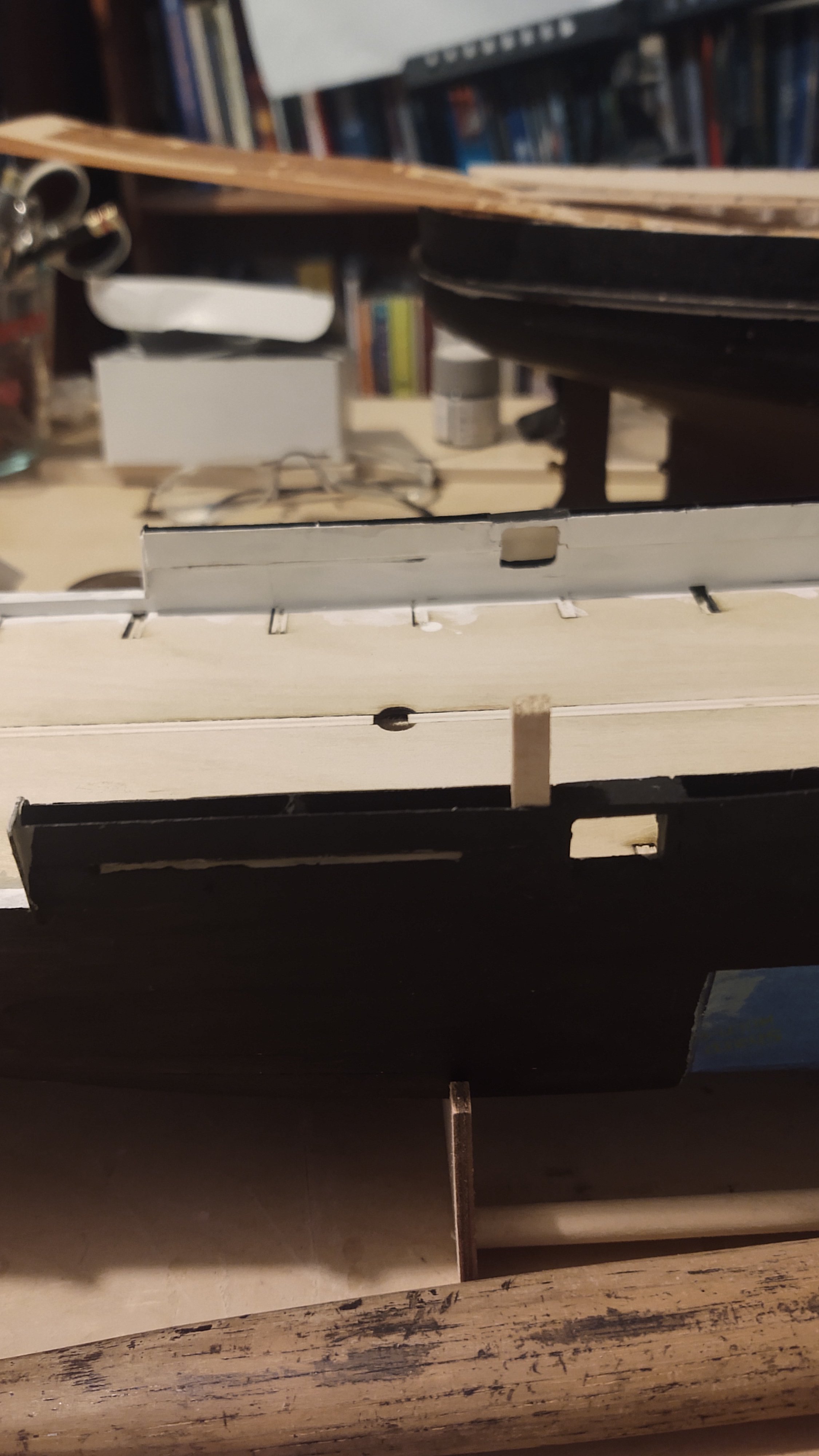
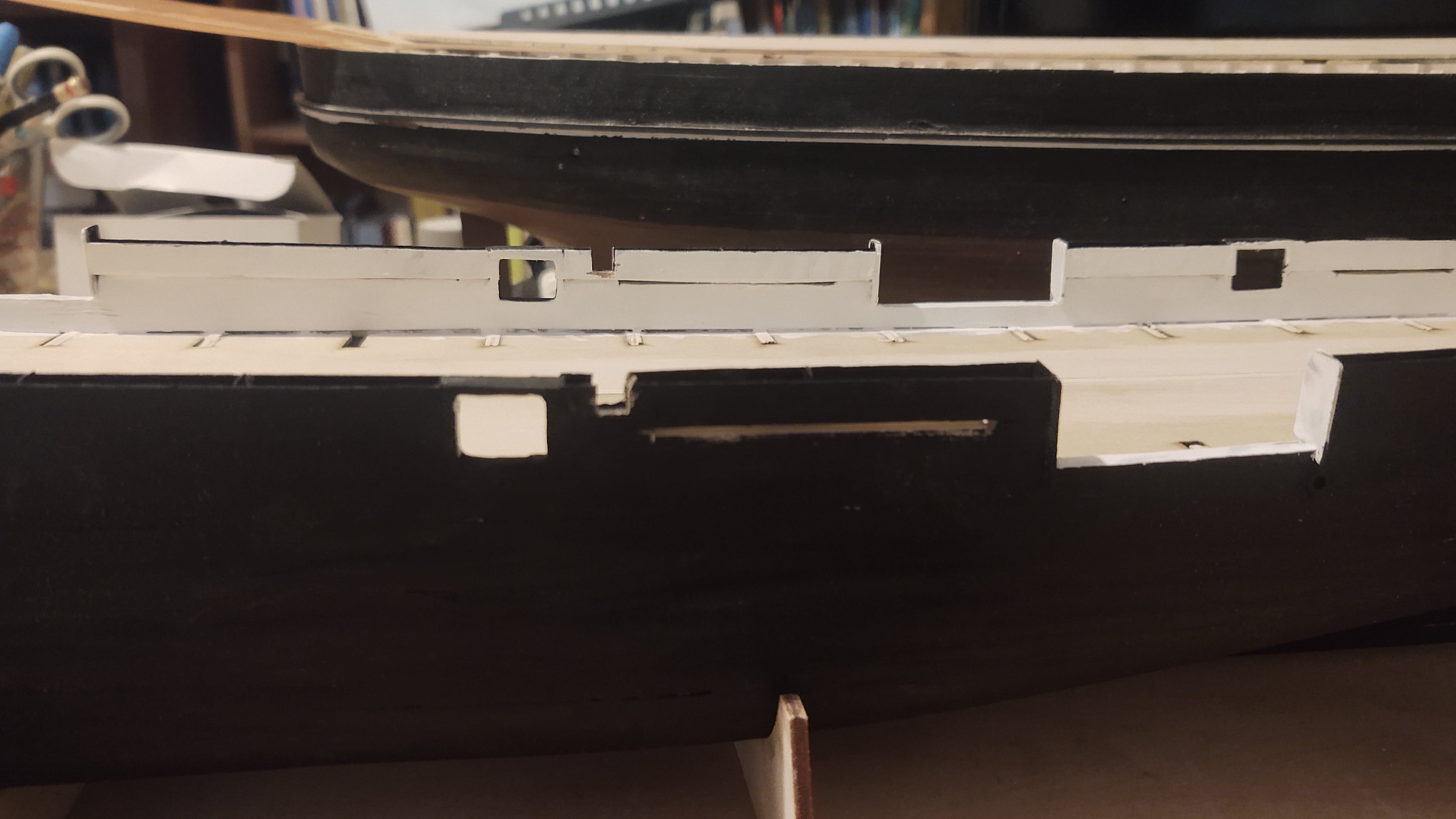
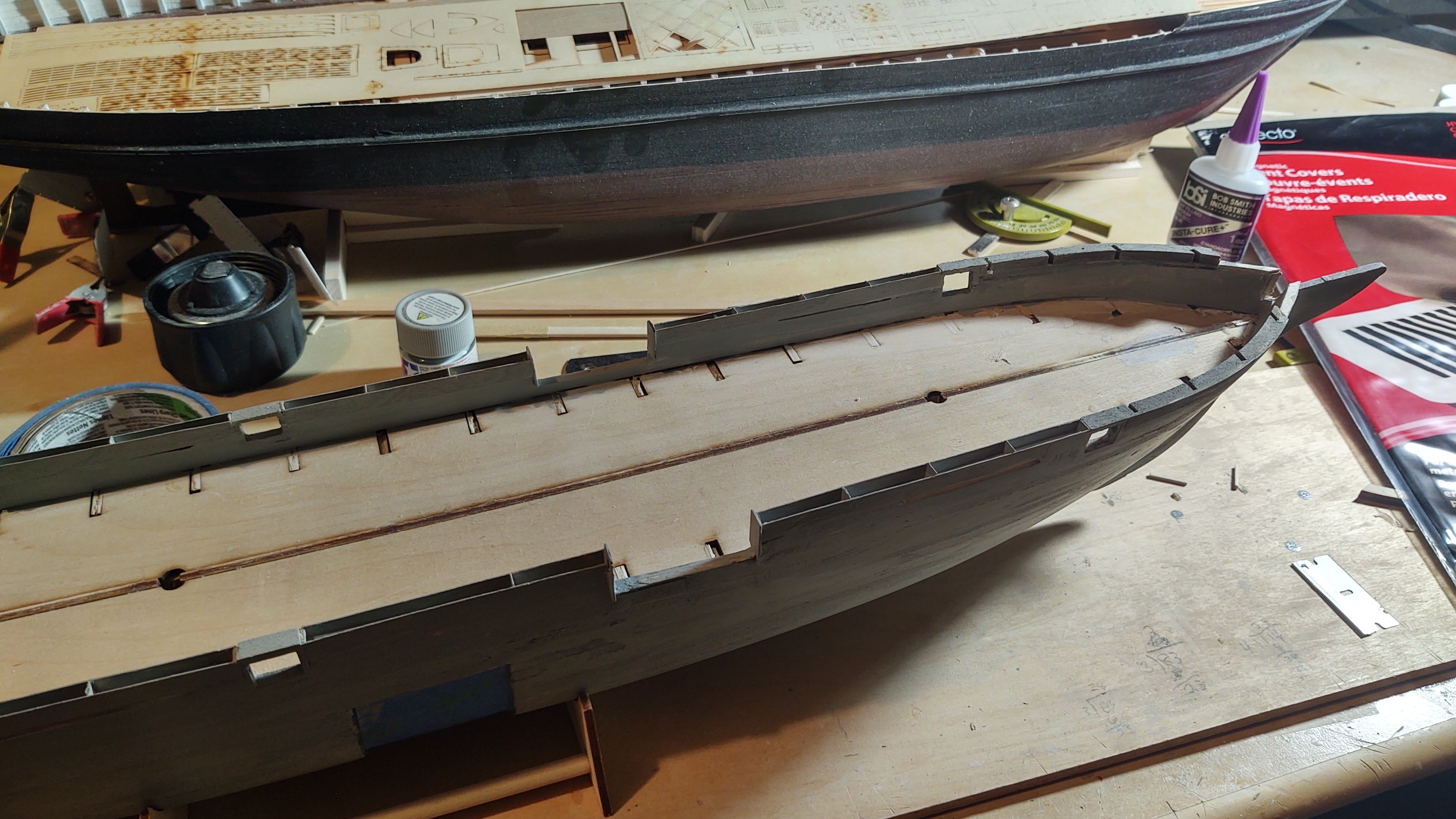
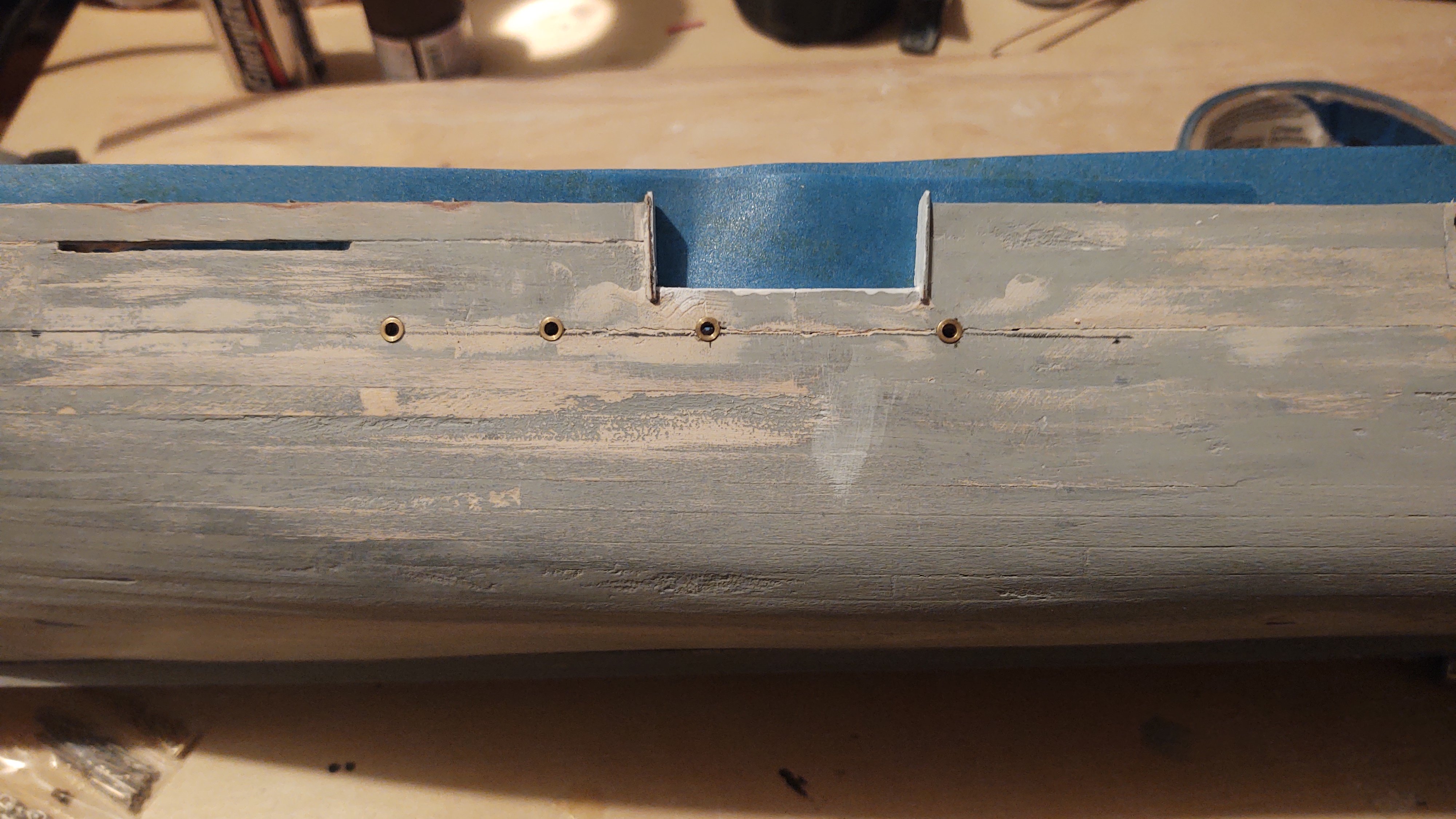
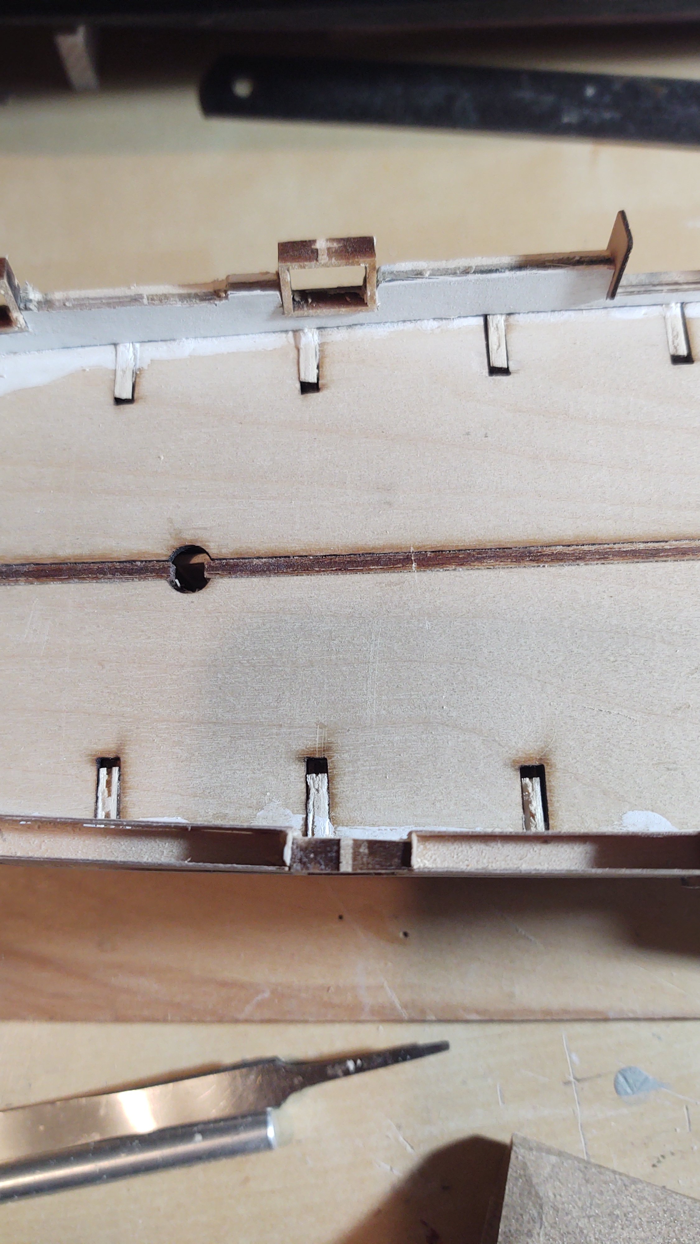
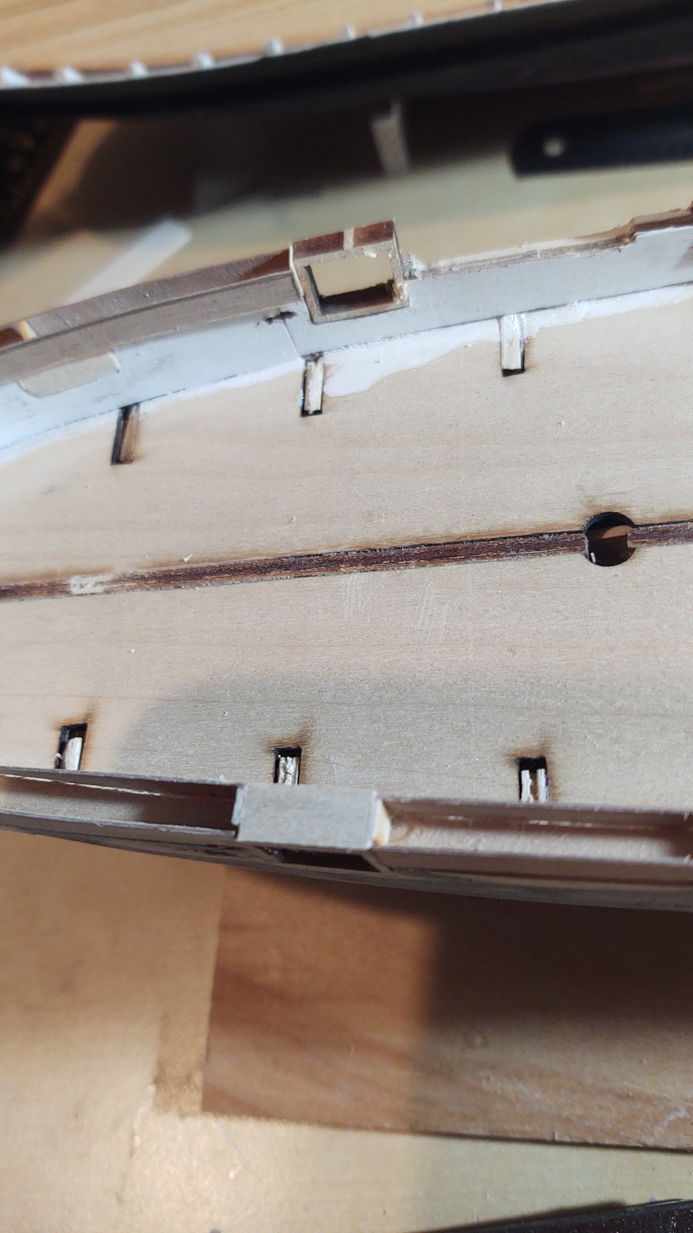
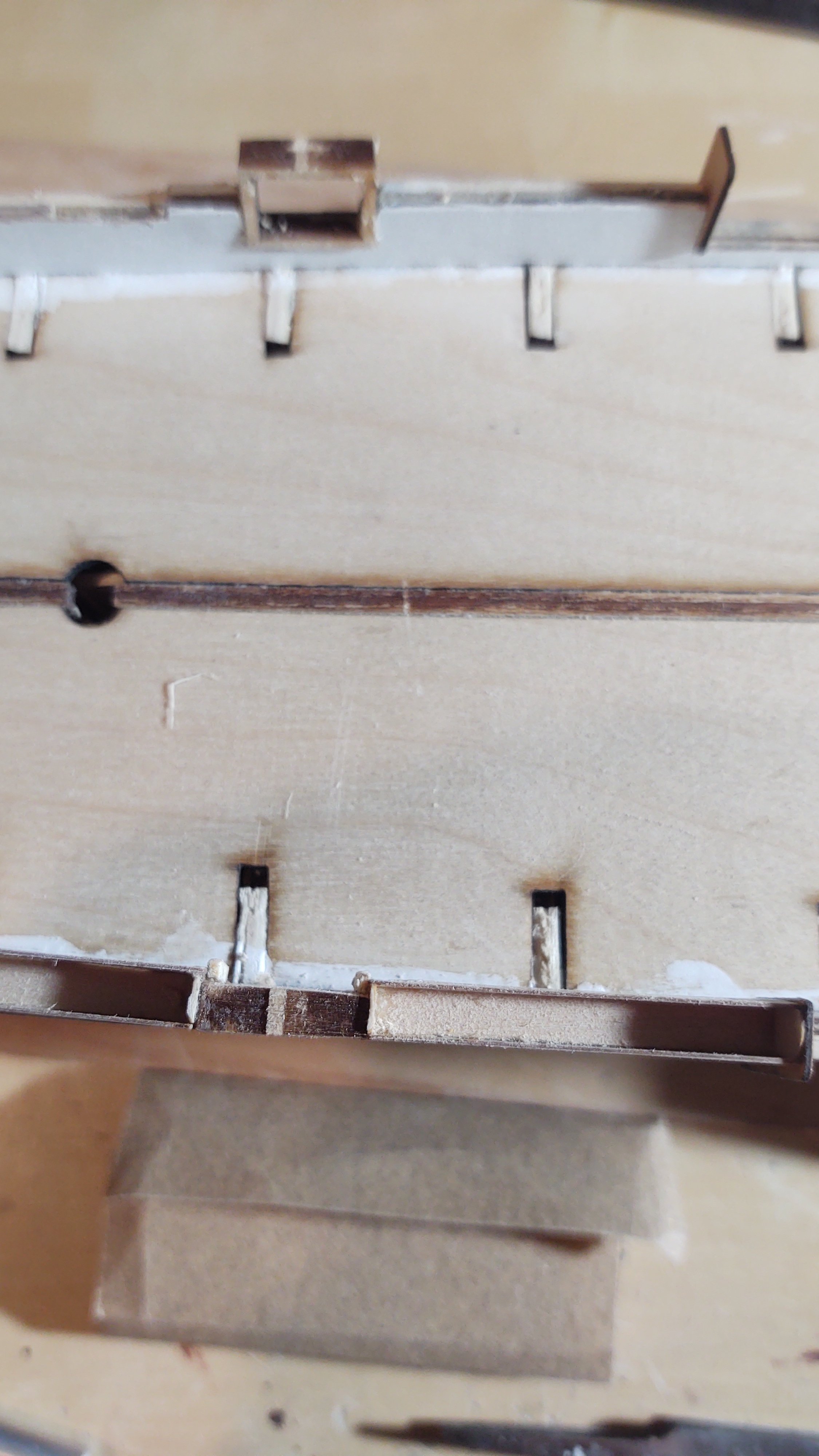
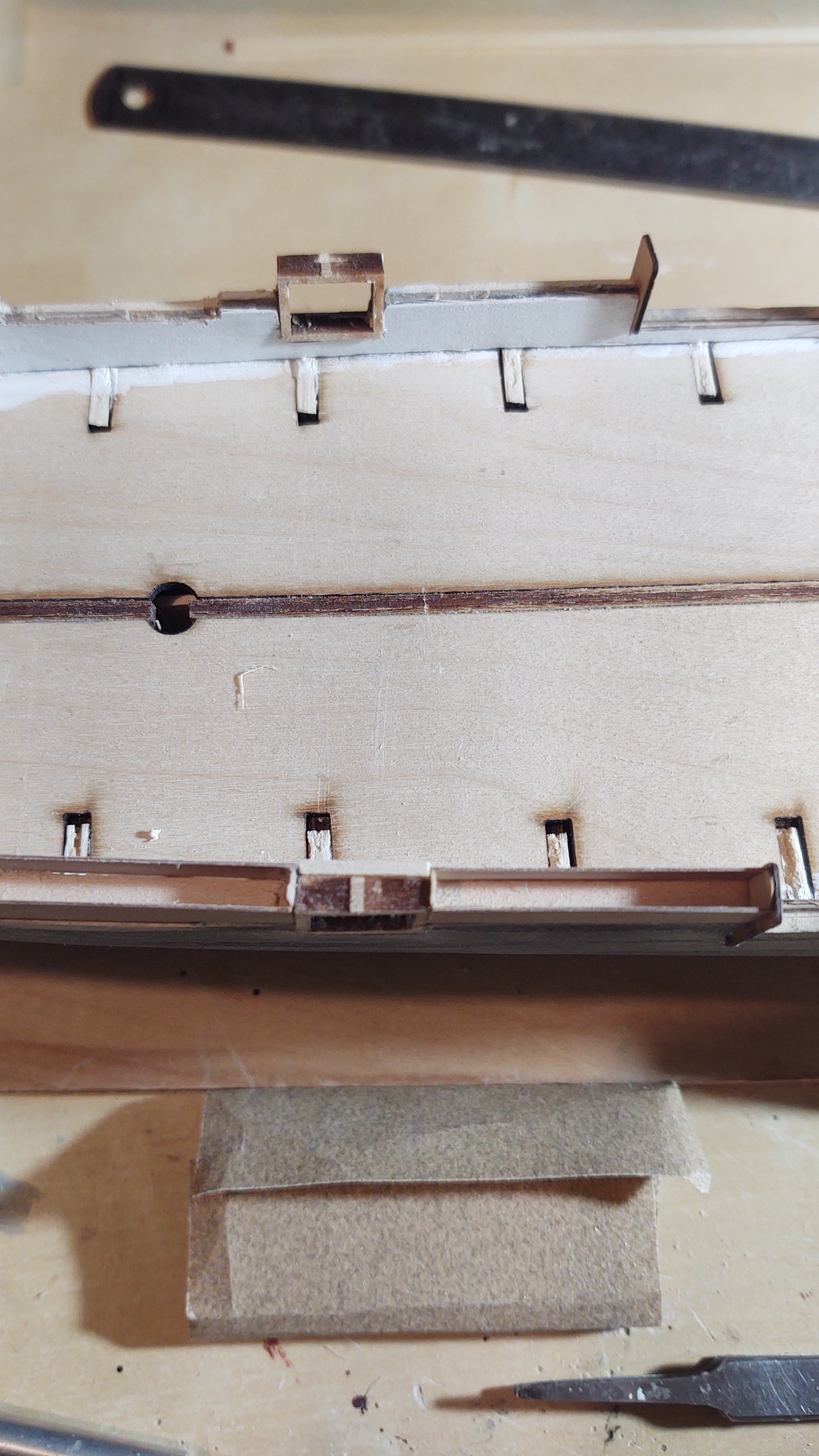
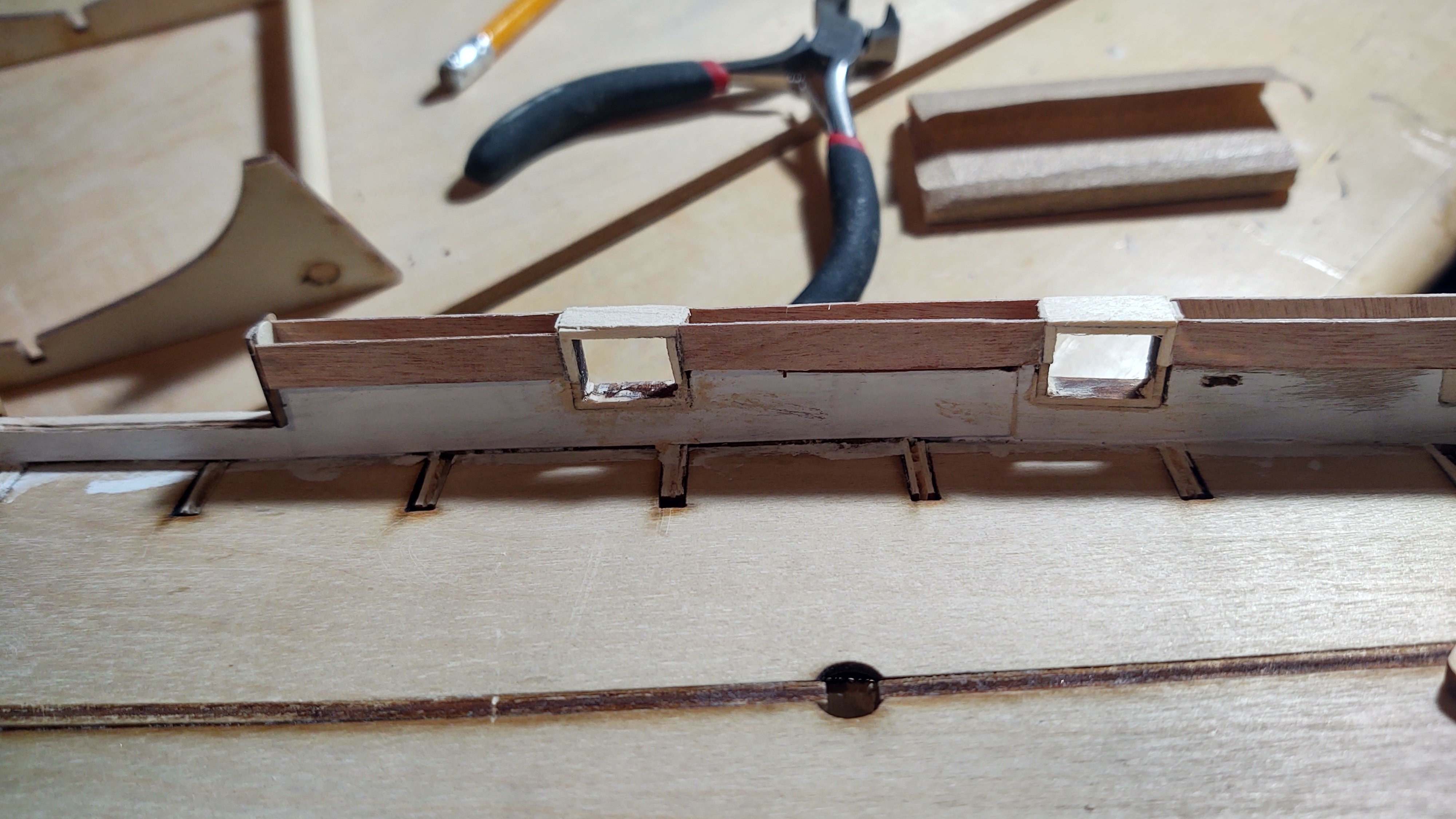
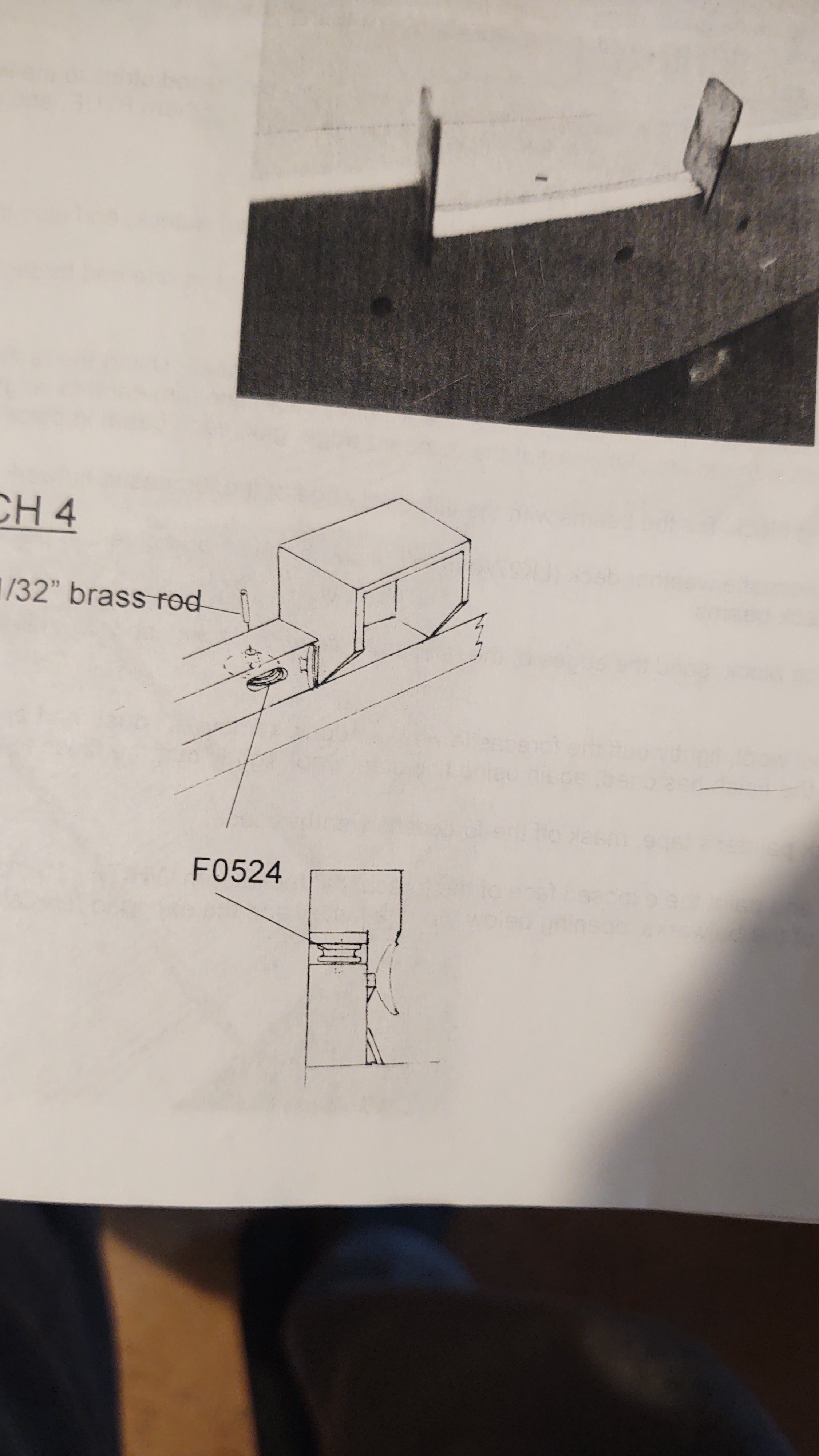
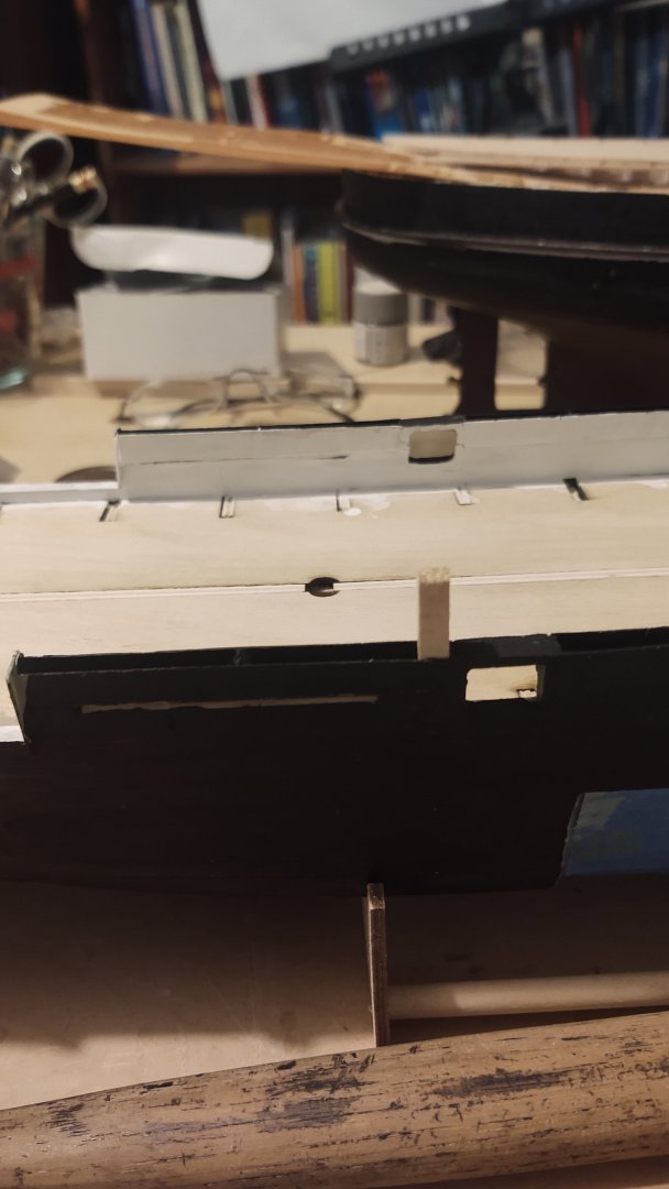
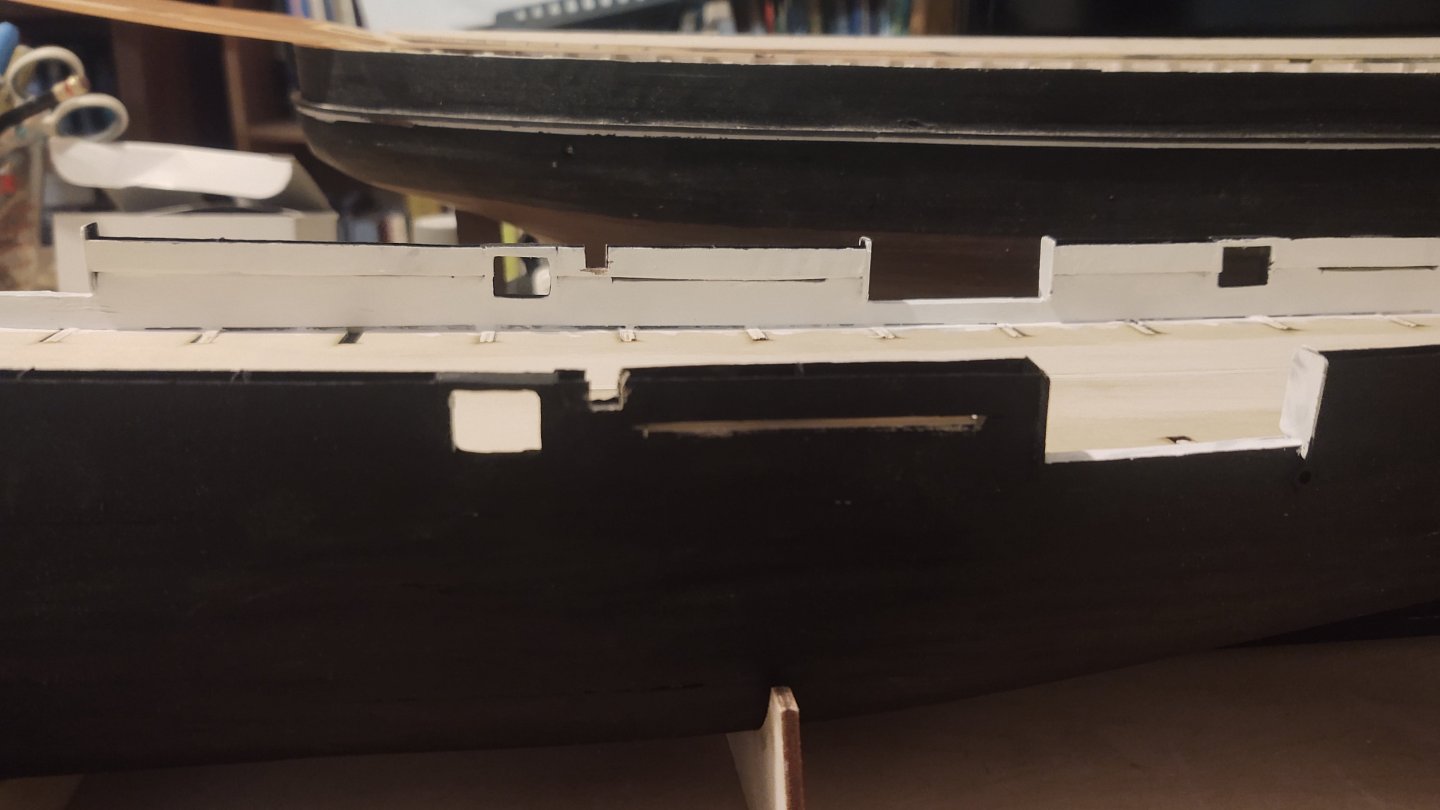
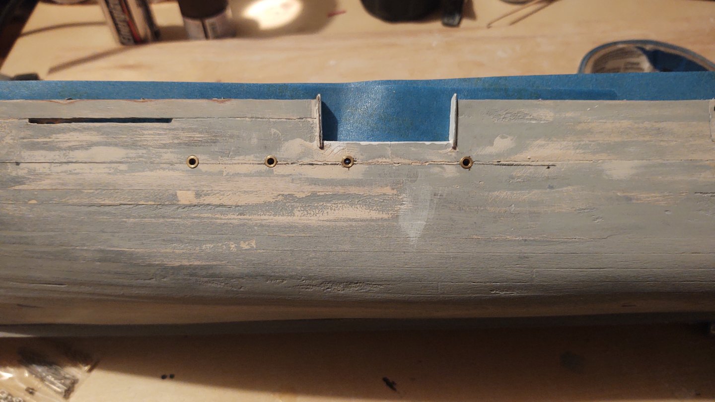
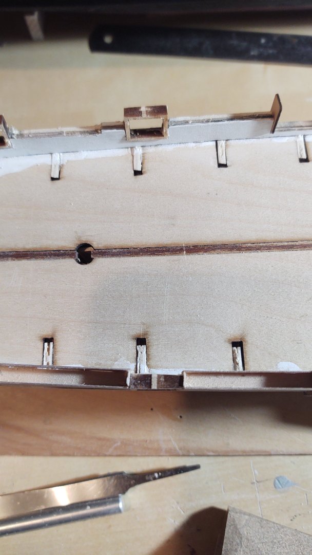
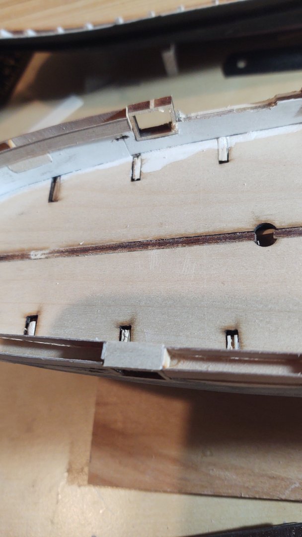
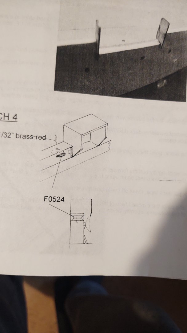
So, it's been a while since I have done much to the Kearsarge, I've been focused on the Discovery for a while. However, time to restart this log as well. I was putting in the hammock netting when I was last working on this, but I realized that I made a mistake, somewhat early in the proceedings. You may recall from an earlier post that I didn't understand this: Well, looking at the model as it was coming along, as well as photos of the real ship made me realize that this was not the way that the interior of the ship should look (you want to look at the gunport on the bottom of the picture. The gunport is the thickness of the hull, but you want it to be the thickness of the hull below the hammock nets and the thickness of the hammock nets in the area where the hammock nets are. That is what that picture in the instructions was trying to show. It just wasn't clear why, or, for that matter where the change should occur. This requires fixing, so this is what I am doing. Step 1: Again look at lower gunport. I thinned 1/16 square stock to about 1/16 by 1/32 so that it was the thickness of the gunport, and then glued two sections the height of the hammock netting to either side of the gunport. It sticks into the hull, but that's okay, I'm going to sand it later. Step 2: I put another piece of the about 1/16 by 1/32 wood as a cross piece. Step 3: Add a piece of 1/4 by about 1/16 wood to cover the whole thing: Step 4: Sand until even with the top of the hammock netting and the inside of the hull/hammock netting: Much better. Hopefully, this will keep someone from making my mistake. Six more to go as the hammock netting gets put into place. Regards, George


-
Oh. My bad. I think I used 4 (+1)sizes of thread for the standing rigging. They were 0.035, 0.030, 0.025, and 0.020 and some standard mercerized cotton thread for the ratlines. I kinda followed the size guidelines, matching the listed sizes to those 4 diameters, but making sure that things got smaller as I went up, and if something looked too big (or too small) I adjusted accordingly. I don't have a list, I just did what (approximately) matched the listed size and looked right. Hope that helps, GAK
-
Rick, I assume that you mean on the Flying Fish, not the Discovery? The problem I ran into was that the line sizes (e.g. 8.5 inch shrouds) on the plans were inches circumference, not diameter. So divide by 3.14 to get the actual diameter and then divide by 96 to get the right scale size. I came to the same conclusion - that they were using aircraft carrier mooring lines as shrouds, until someone explained this to me. That made a huge difference, those 8.5" shrouds went from 0.09 to 0.028 which seemed a lot more reasonable. If that isn't the problem - my apologies. Regards, George
-
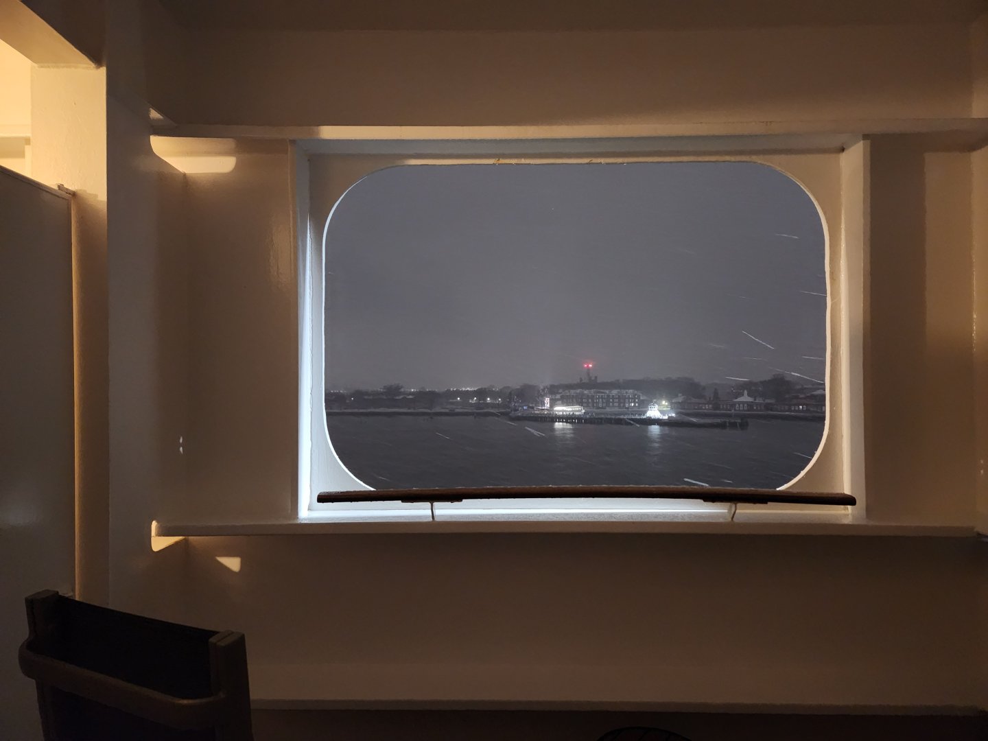
As they say, "apart from that Mrs. Lincoln, how was the play" 😀 Actually, it was very relaxing. Because I'm job hunting right now, and my wife and I both have elderly parents, we didn't want to completely disconnect, so we paid for basic internet for one device. However, it was actually pretty easy to ignore the outside world, which was our goal. We were still in the bottom 10% of the age distribution on the ship (there were some families with kids, and one or two newlyweds), but this is definitely a more mature crowd. It's Cunard, so more about lectures, trivia, and ballroom dancing than hardcore partying as you might see on a lot of the other ships. And although they weren't overly fussy about it, people dressed nicer for more events, which was kind of fun. I mean, I brought and wore a tuxedo two of the nights - I think the last time I put one on was for my sister's wedding in 1999, and, like I said, it was fun. The stabilizers worked well, the ship was busy without being overly crowded, and I could run on the promenade deck without much trouble. The negatives: We began to find the food a bit boring. It was British, all the time. I don't know why they didn't bring say Indian food, or Italian food into the main dining room occasionally (they had specialty restaurants for both of those cuisines). And if you are really prone to seasickness the ship rolls more than say a cruise ship in the protected waters of the Caribbean. But those are mostly nits if you are just doing a one way trip. A lot of the people were on for a 28 day cruise (Southampton -> Caribbean -> New York -> Southampton), and I think those nits would start bothering me more by that point. Bottom line is that if you have the time to spare, the cost isn't radically different than an economy plus airline ticket, and it is a lot less hassle than an airport (although I will say that the terminal in Southampton is a bit of a dump). If my 88 year old father and his 85 year old girlfriend got a yen to go to the UK, I'd send them this way - cheaper, more fun, and less stressful - no jet lag, for example. And it is a classic journey, one that our grandparents took. I didn't get to see the Statue of Liberty coming in (I was in quarantine and we were on the wrong side of the ship to see it from our cabin), but my wife did, and that's a pretty iconic experience. Regards, George PS - We booked a "sheltered balcony" cabin, which I can't recommend enough. They are lower in the ship (we were on deck 5), the common areas, in contrast to most ships were on very low decks (generally 2 and 3) so that the dining room and show venues don't roll too much, and the main promenade is on deck 7. We wound up not taking a lot of pictures of this, but your cabin has a double wide glass door, so lots of natural light, and a small balcony with two chairs and a table. But unlike the balconies on the higher decks (basically open, and separated only by glass partitions, these balconies are cut into the outer part of the ship's hull. This is the only picture we took that shows it well - we were already docked in Brooklyn: Basically, if the wind is howling (and we had 40 knot headwinds + 20 knots of ship speed some days) you don't get nearly as blown around as if you are in the open balcony, but can still step out and get some nice air directly from your cabin (and when I was quarantined I really appreciated that). The visibility isn't as good sitting in the chairs, but in December we weren't likely to be doing that for long anyway, and the sea remained the sea. It wasn't like we were in Alaska or Norway and would be viewing many sights from the ship.
-
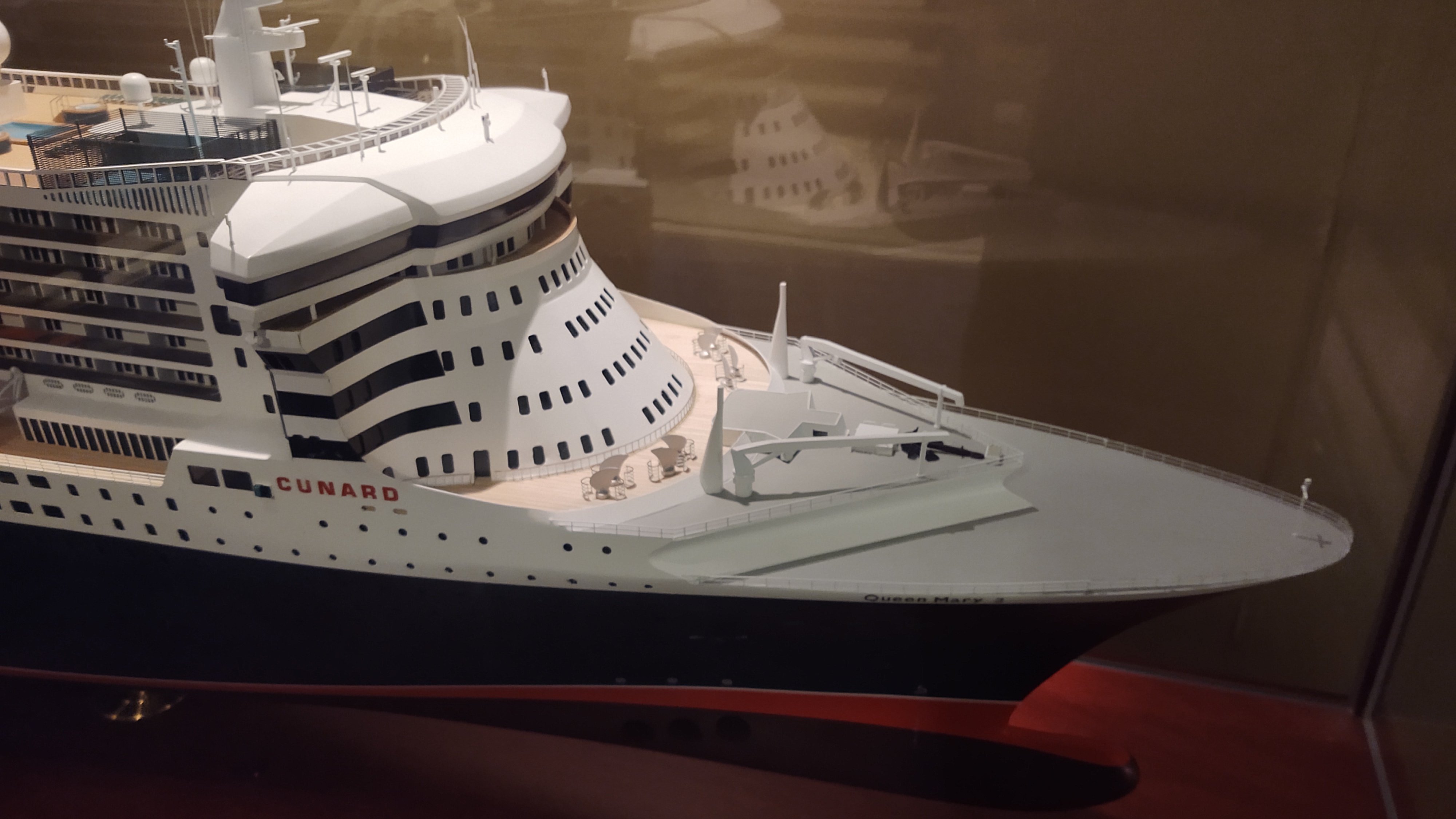
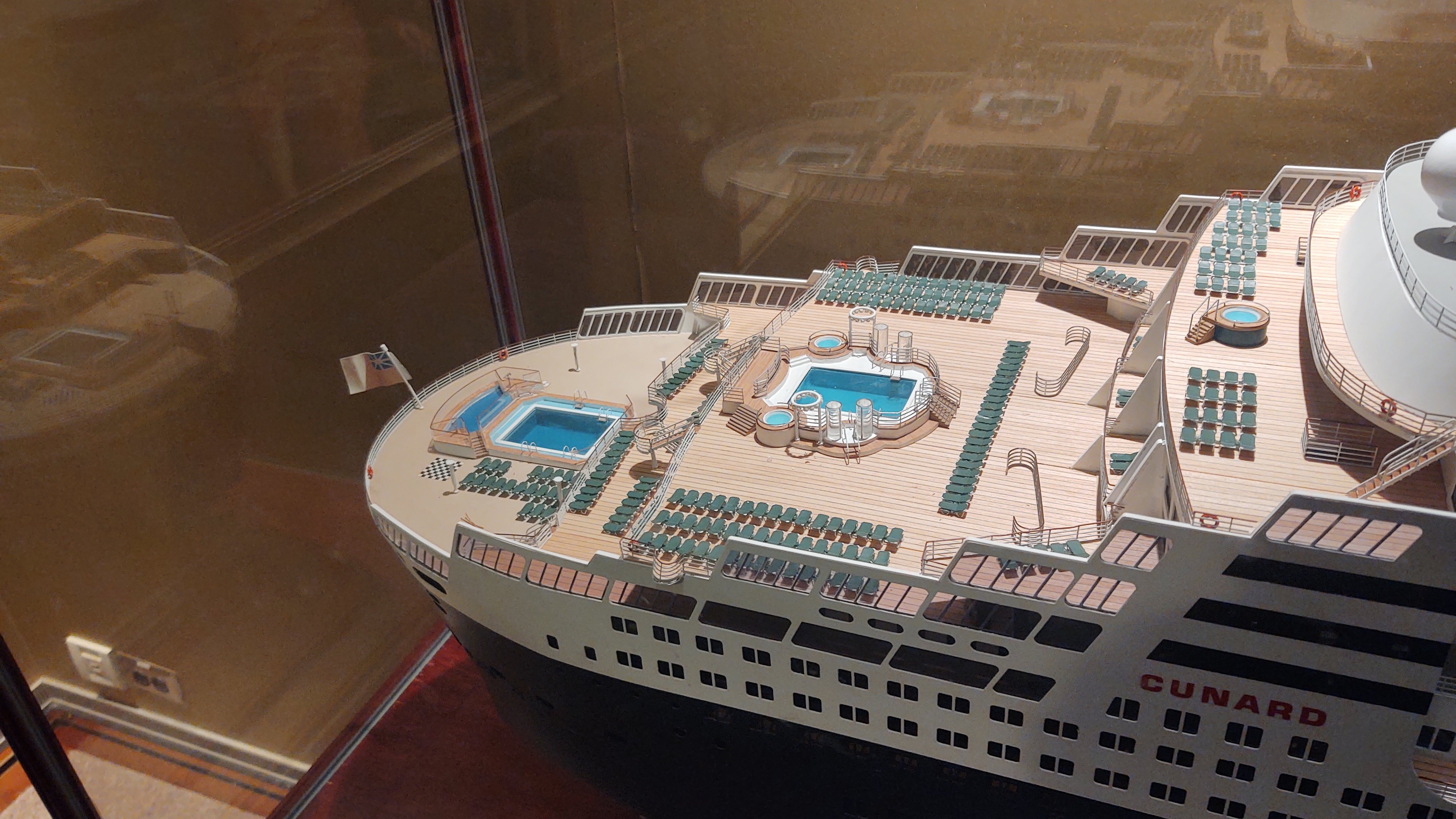
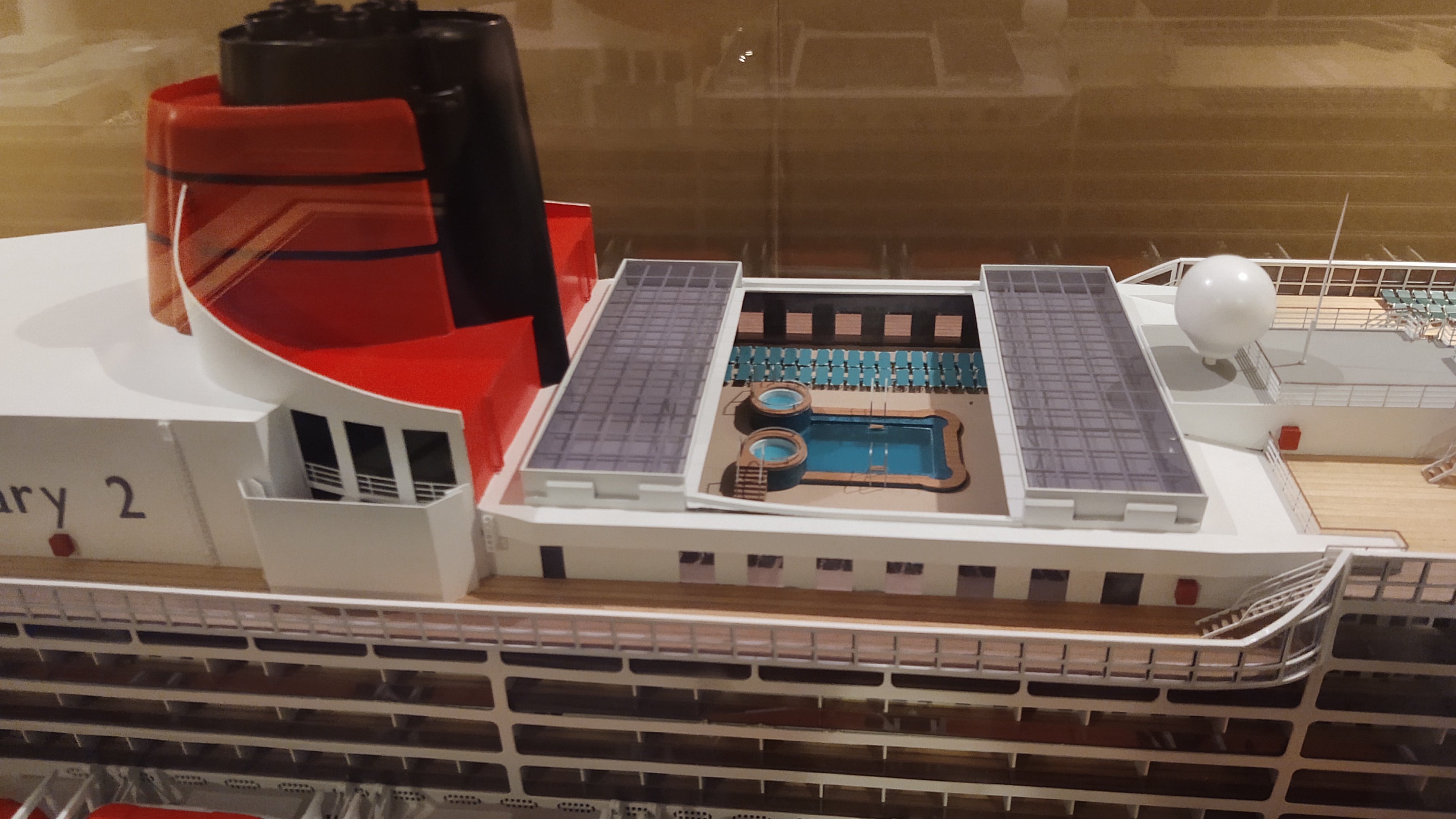
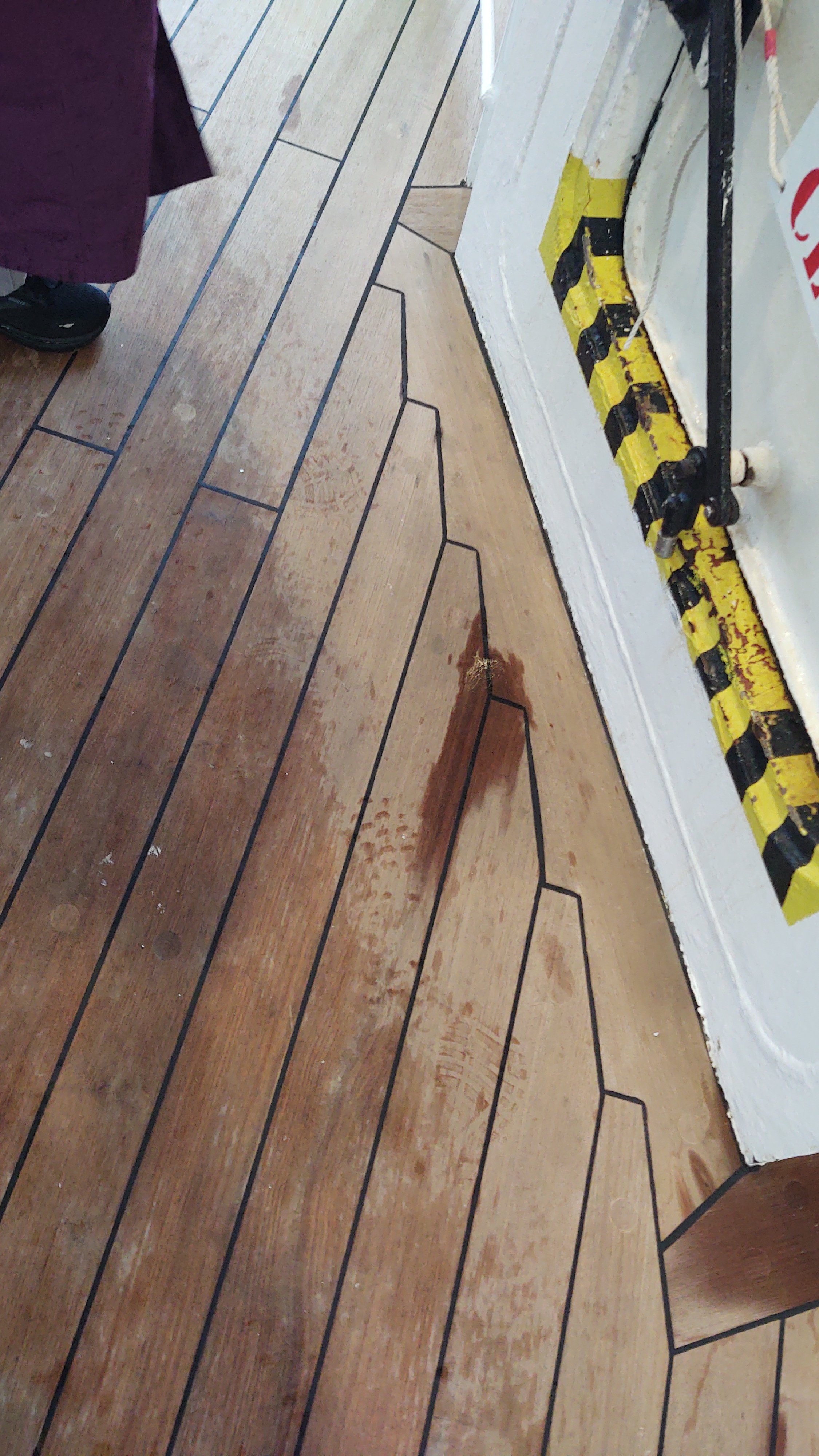
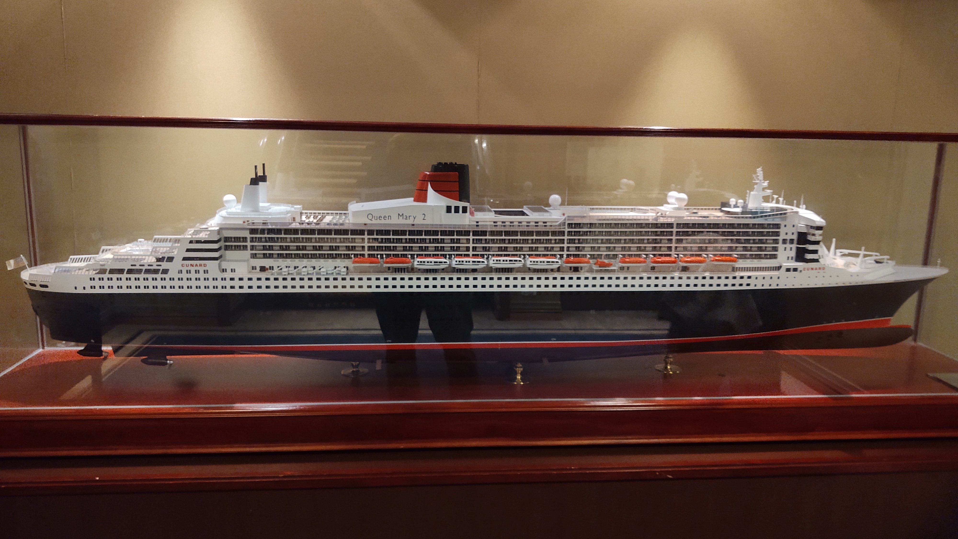
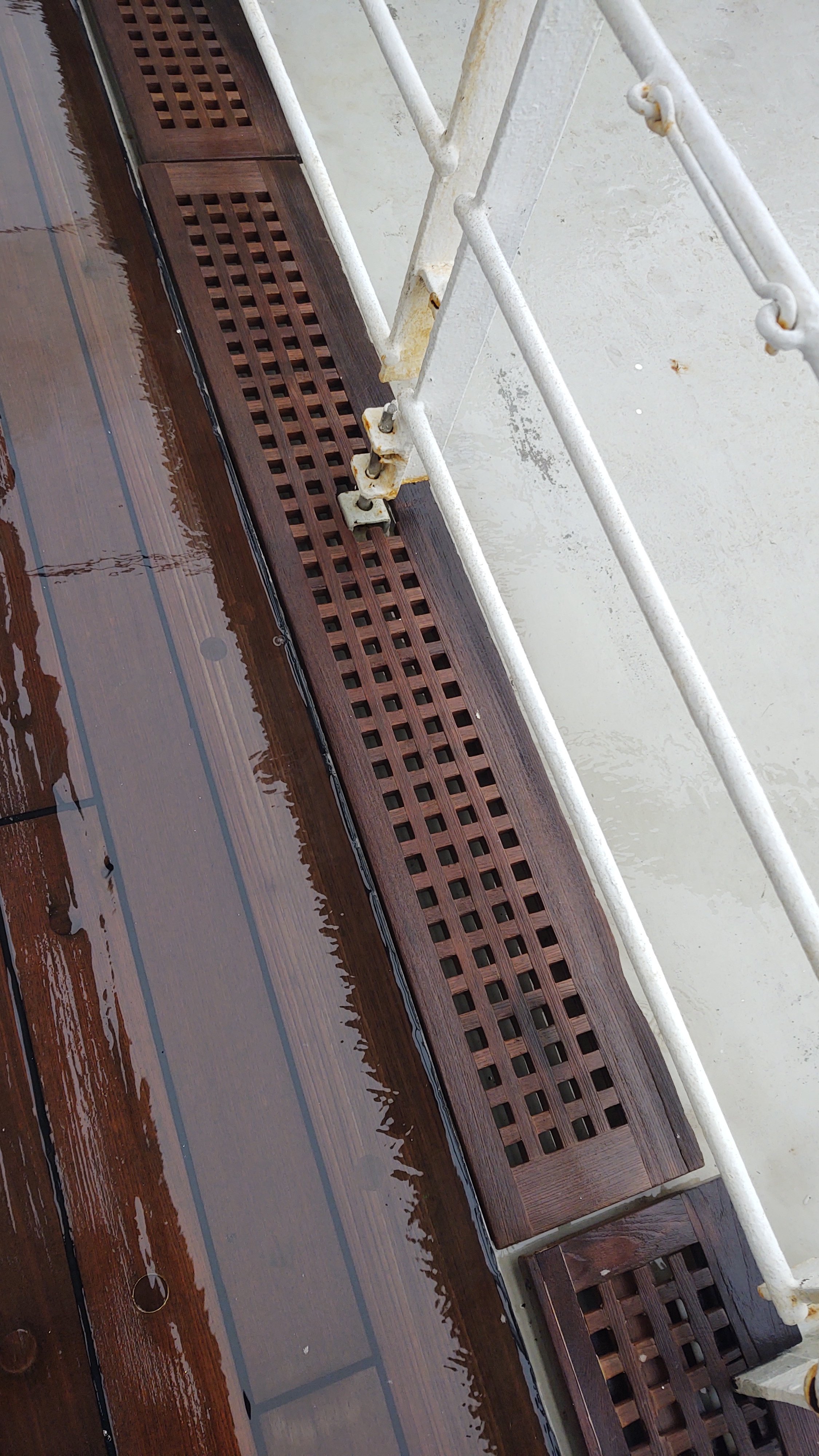
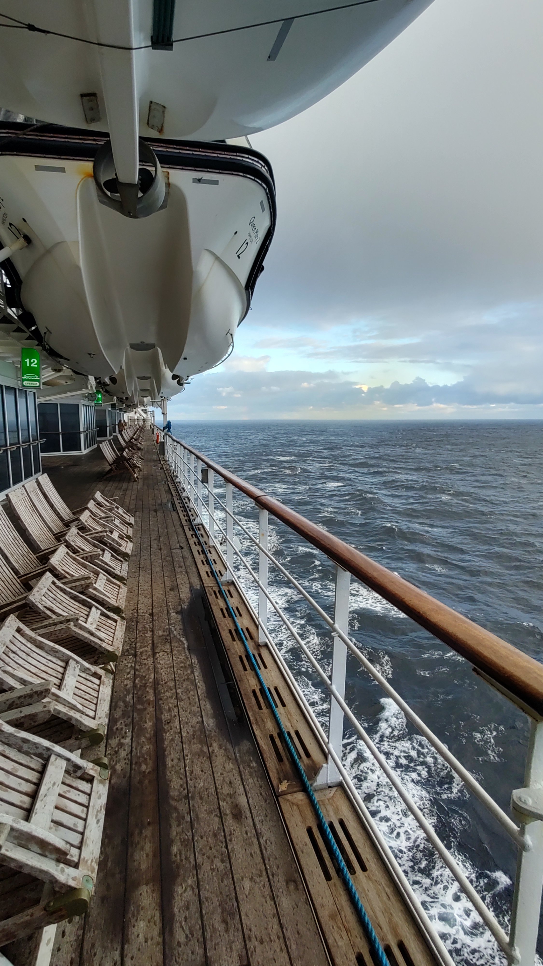
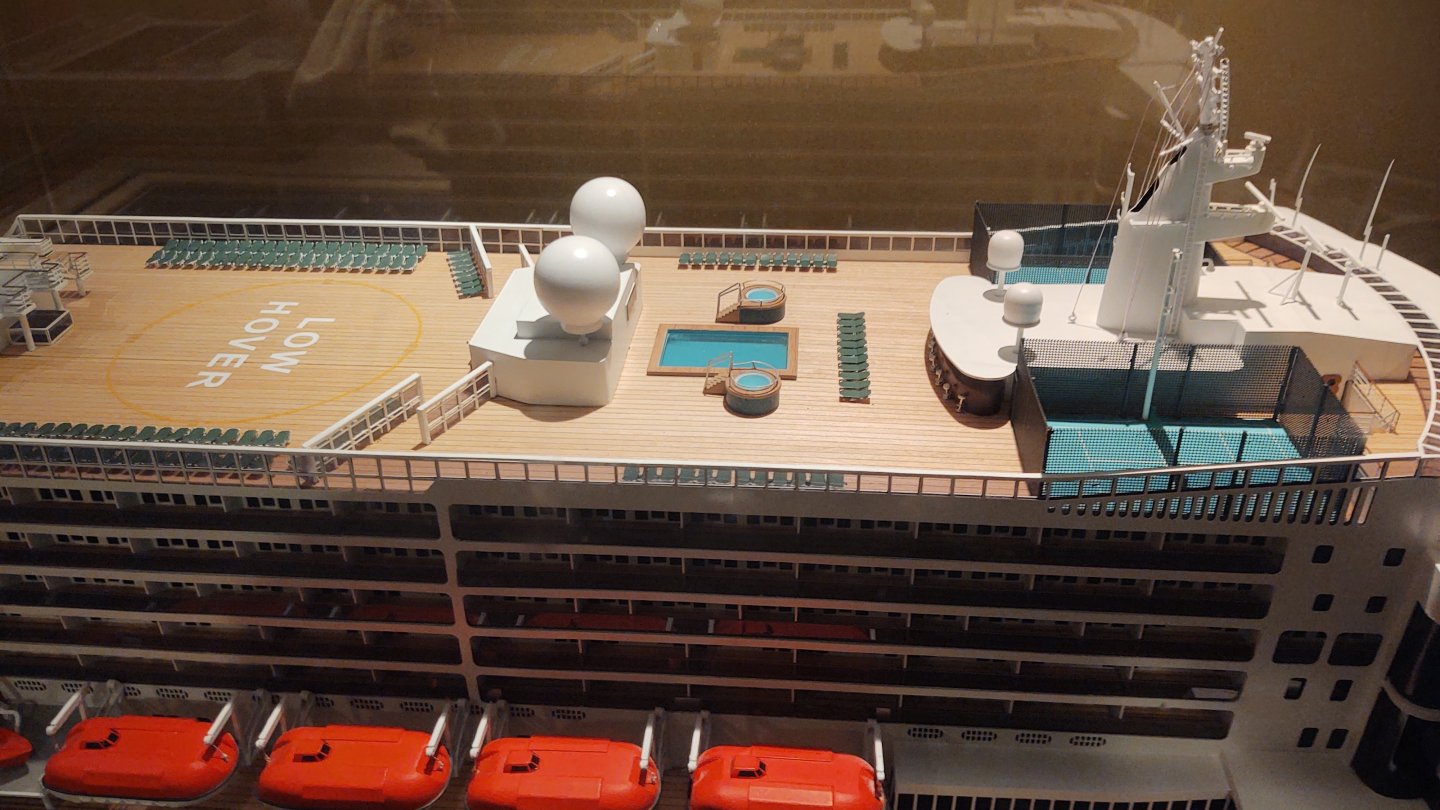
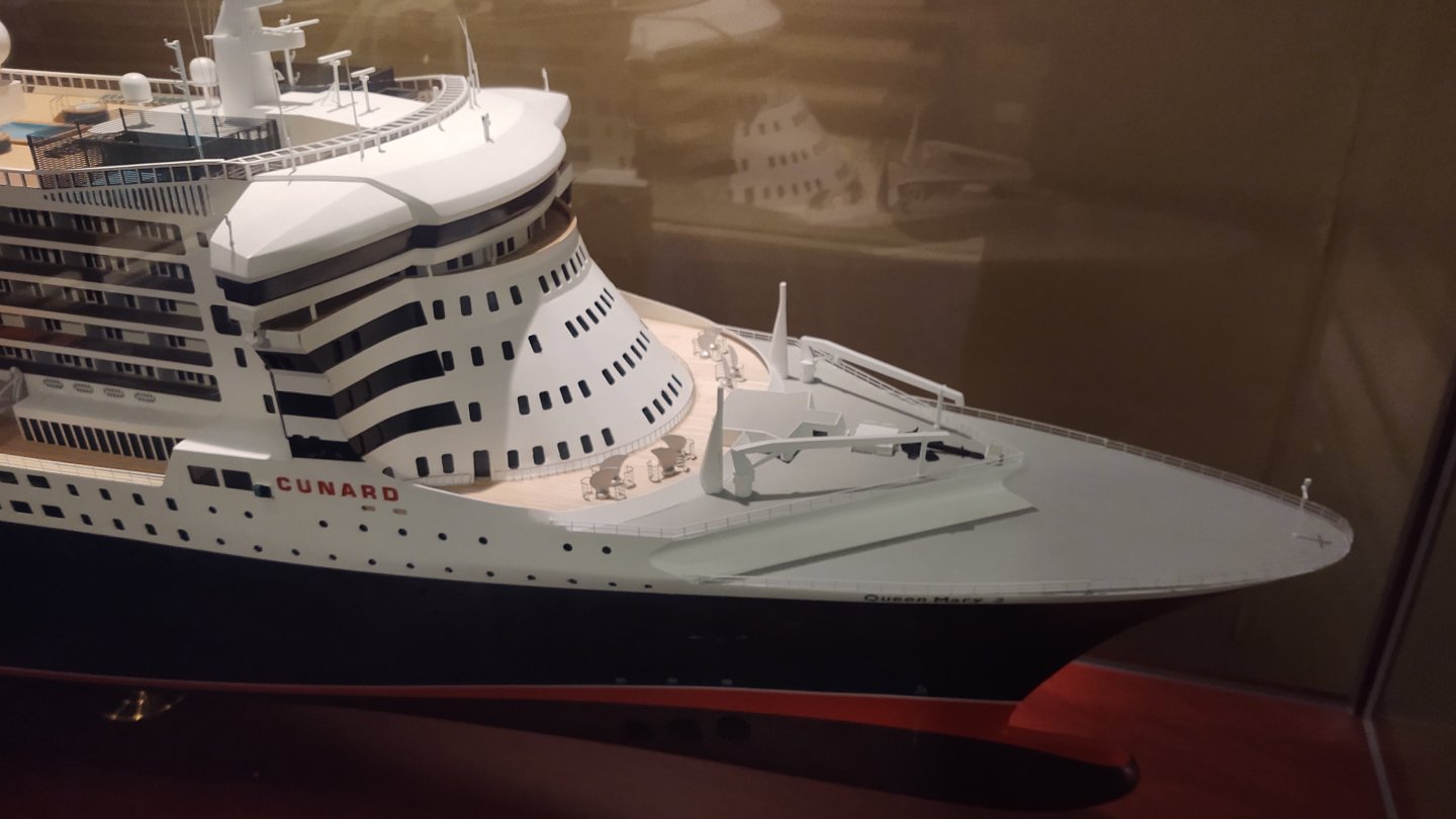
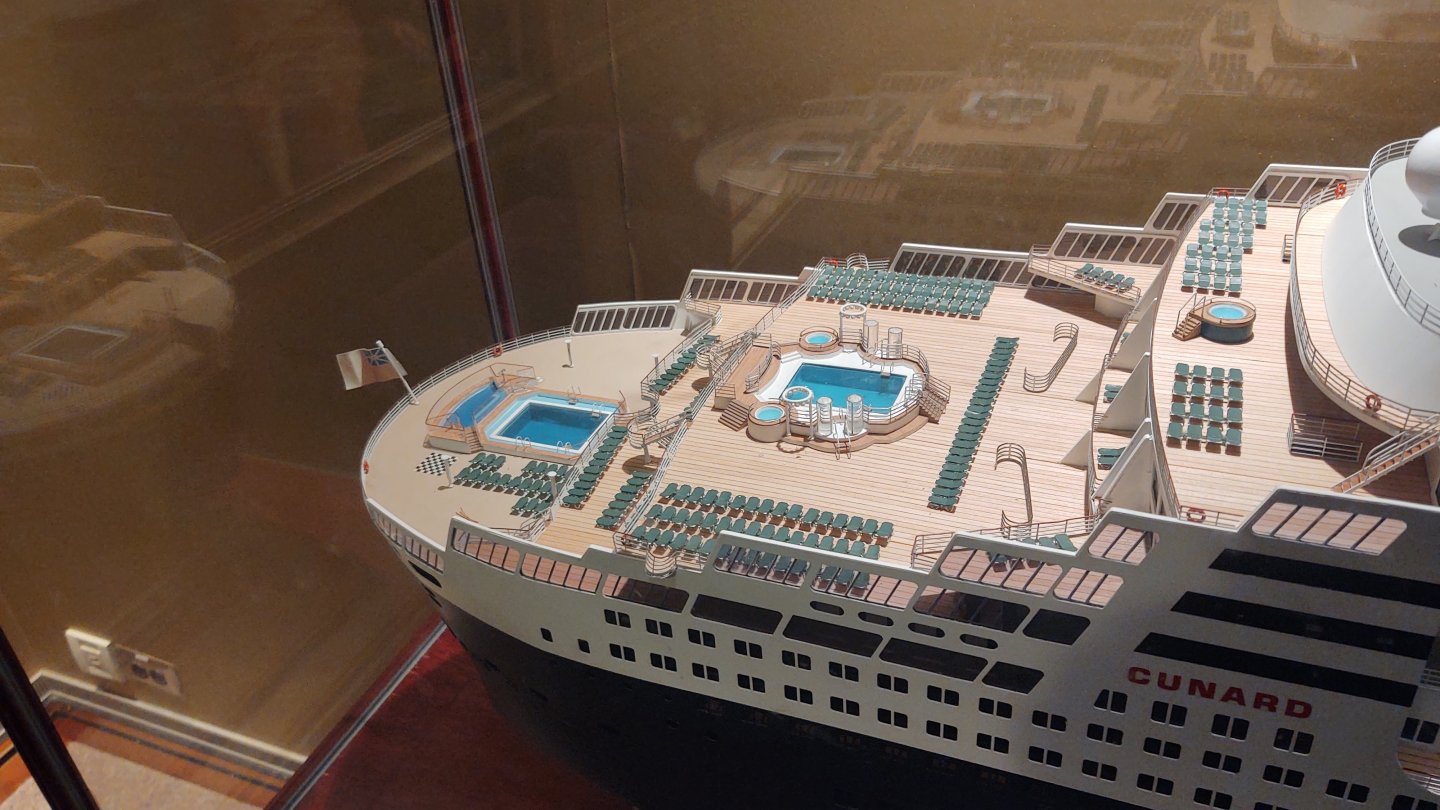
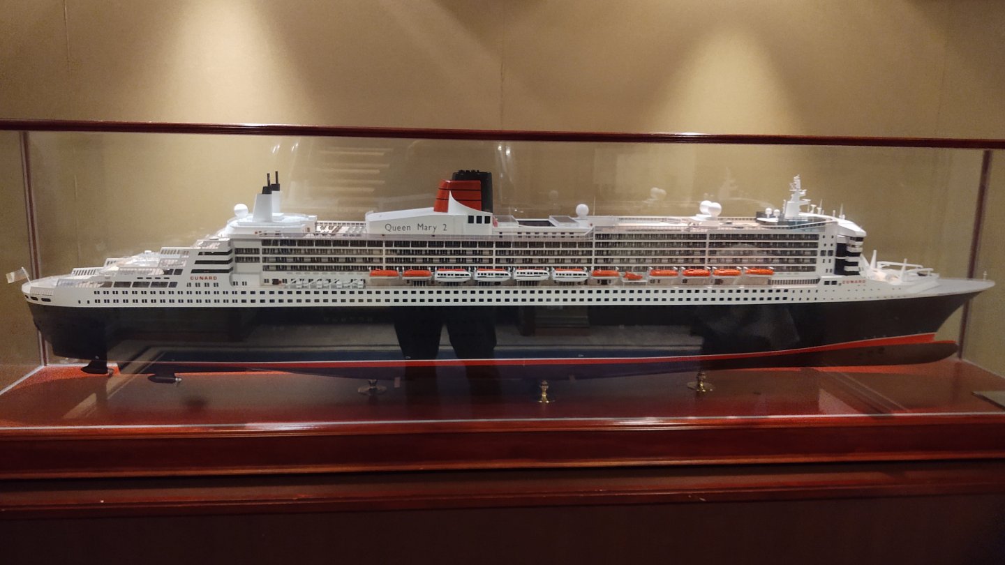
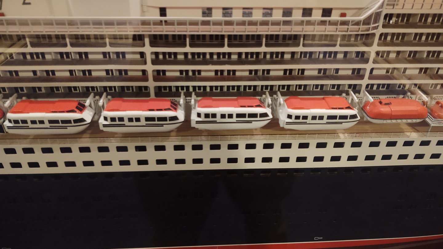
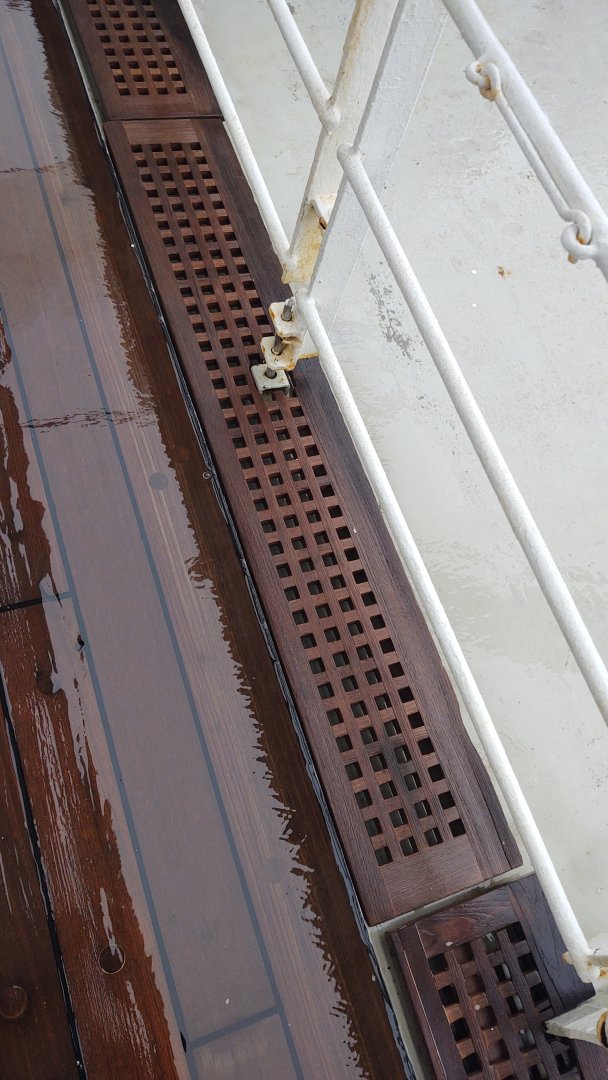
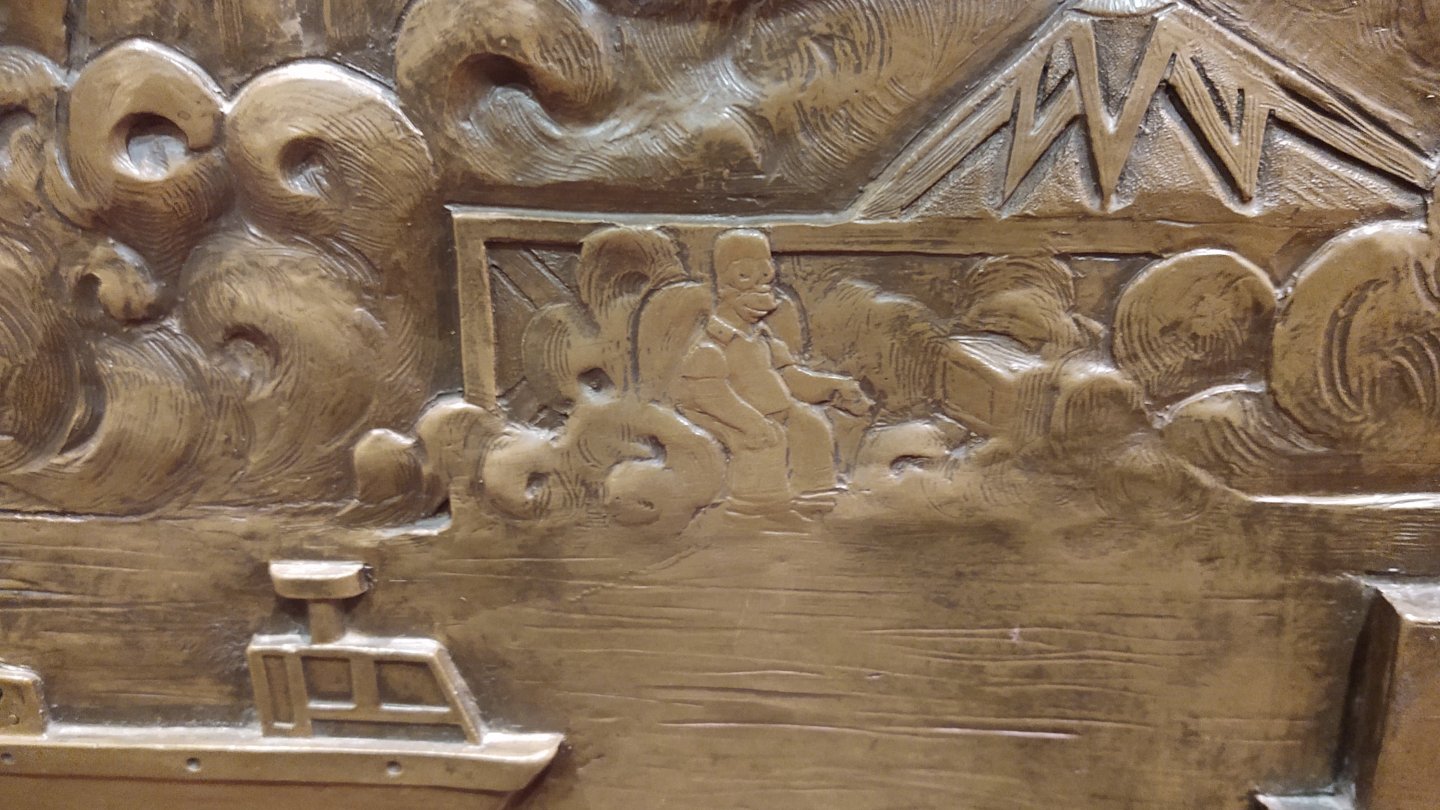
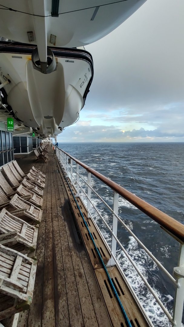
Well, we are (almost) back (sitting in the train hall in NYC. A couple of images for you all. First, a Santa bike ride at London Waterloo on our way to Southampton. A bit of sea: A model of the QM2 (large, scale uncertain): Homer a Simpson in one of the bas reliefs: And two photos of the more things change. Nibbed deck planks: And wooden deck gratings It was a nice trip until Thursday when I wound up with a norovirus infection, which is not recommended. Regards, George


-
Congratulations on retiring, I hope you enjoy it. The model is looking fabulous! George
-
To heck with that! We both intend sail the Atlantic on a sea of wine and meals prepared by someone else. I take your point though. The morning of that storm in Alaska (on the 1950s SS Rotterdam) breakfast was much less well attended than usual, and while we were eating, a wave hit one of the portholes just right and blasted it in. We lifted our feet as water rushed under our table, the crew plugged the hole, and we moved to the other dining room. And hey, Dramamine is OTC. Regards, George
-
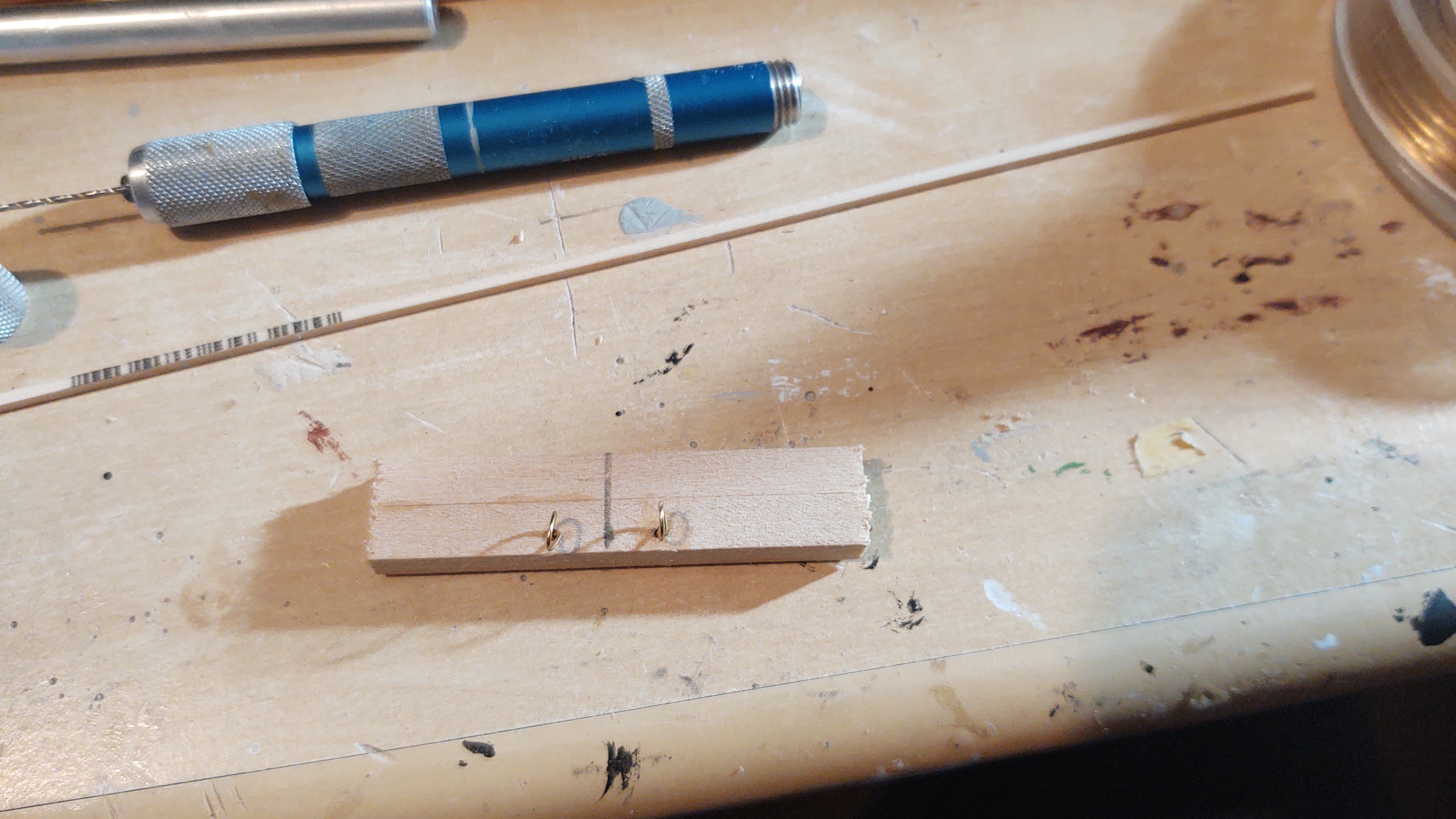
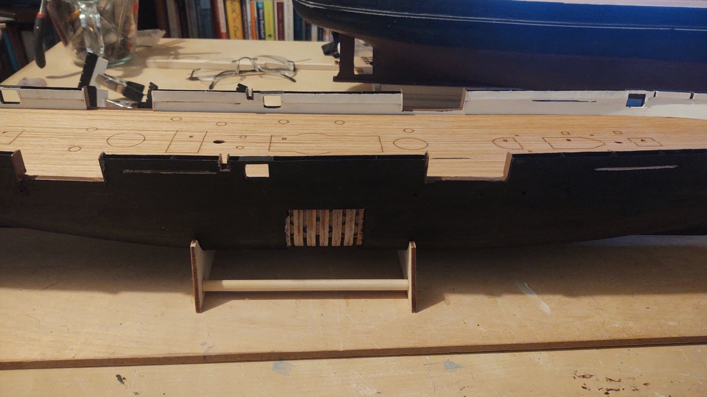
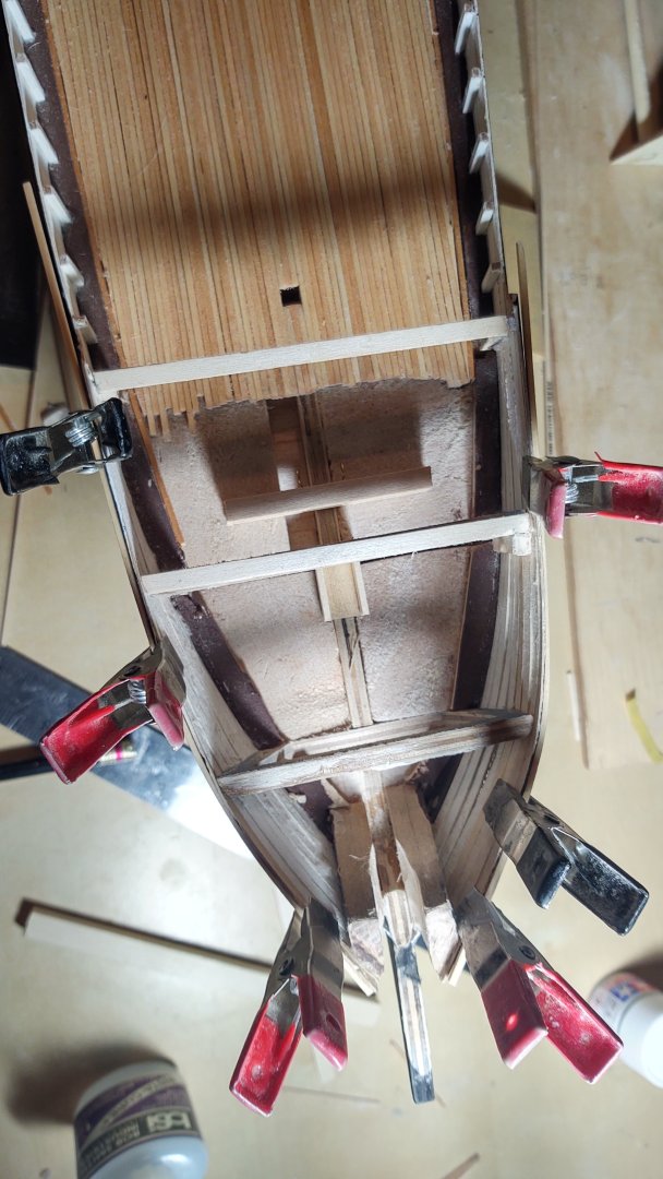
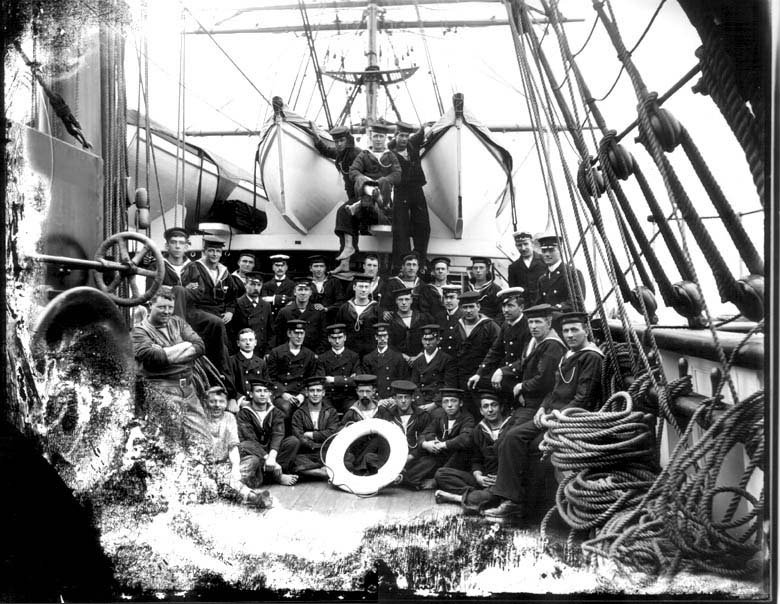
And where they were going, shrinkage would be an issue... Yep. What I have been finding is that you need to be really careful. I was looking at a web page I recently found with a listing of the ship's crew, and some photos. https://www.coolantarctica.com/Antarctica fact file/History/antarctic_whos_who_discovery.php In theory this was about the 1901-1904 voyage. There was a signed photo of the ship included, and I had a start, because it looked like the bowsprit was not the single pole shown in the plans, but the two piece bowsprit/jibboom on the current ship. But, looking more carefully at the signatures, the people that signed were from the 1929-1931 BANZARE expedition, that also used the (post-refit) Discovery. Stuff from Dundee Heritage is much more careful, but they seem to have much more information on the refitted (i.e. current) ship than the original. Incidentally, if anyone actually wants to make the current ship, Dundee Heritage has been digitizing the refit plans - they are there for the asking. An update. I decided to tackle the forecastle next. It turns out I needed to repair a broken chunk of the forecastle first, but simple to do. There are two things that need to be in the forecastle (which is sealed off): a resting place for the bowsprit and an anchor point for the lower main forestays. The latter is here: And here are the two of them mounted in the forecastle. The clamps were holding a couple of planks I was pre-bending to become the edges of the deck planking on the forecastle. I then installed the sub deck (first cutting a convenient path for the bowsprit in one of the supports built into the subdeck, and then planked it. A couple of the planks took the stain way more than the others, but, it is what it is. I bought them at my local hobby shop, I wonder if maybe they were a different batch. Here is the ship as a whole from two slightly different views. Next up is going to be the bulkhead that closes off the forecastle (minus the doors), rudder and prop, the decorative work on the prow, and then the main rail. Finally, here is your historical Discovery photo for the entry. This is the crew looking forward, sitting between the main and foremasts. The structure on the left (aft) is the above deck portion of the engine room and one of two reels attached to that structure. Good views of the primary boat frames. We learn several things from this photo. 1) The main mast also has tied ratlines, rather than the slats on the current ship (a previous photo indicated that the foremast was similar. However, I think that the shrouds are wire as indicated in the plans, as opposed to the foremast whose plans (and another photo) indicate are hemp (no metal within 9 meters/30 feet of the magnetic observatory). The modern ship has a bulge in the main rail to accommodate the chainplates that are not shown on the plans and that don't seem to be present here. Finally, the modern ship has the metal engine room structure painted white, and that is definitely not the case here. It's not black/navy blue - compare the color with the sailor's uniforms - maybe just raw steel? But I would assume you would want some kind of protective coating on anything going to sea - some kind of gray? Will have to noodle on that a bit. This is probably my last update for a couple of weeks. My wife and I just turned or are just about to turn 60, so we are taking a bucket list trip, flying to London on Wednesday, and taking the Queen Mary 2 from Southampton to New York. It's surprisingly affordable this time of year (perhaps because the North Atlantic is rough and cold?), so we figured what the heck. We've both spent plenty of time at sea in rough weather, including a winter storm (40 ft seas and 75 MPH winds) off Alaska on our honeymoon and the ability to disconnect will be good. As always, thanks for looking in and the likes. Regards, George


-
Thanks Keith! It's hard to judge exactly, but my read is that the planks in the photo above are between 4 or 6 inches wide (depends on how big the sailor's feet are). As a result, it's probably a bit small as the planks are 1/16 which is to say 4.5 inches at scale. The next commonly available size was 3/32 which is 6.75 inches at scale, and I prefer to err on the small rather than the large side. Regards, George
-
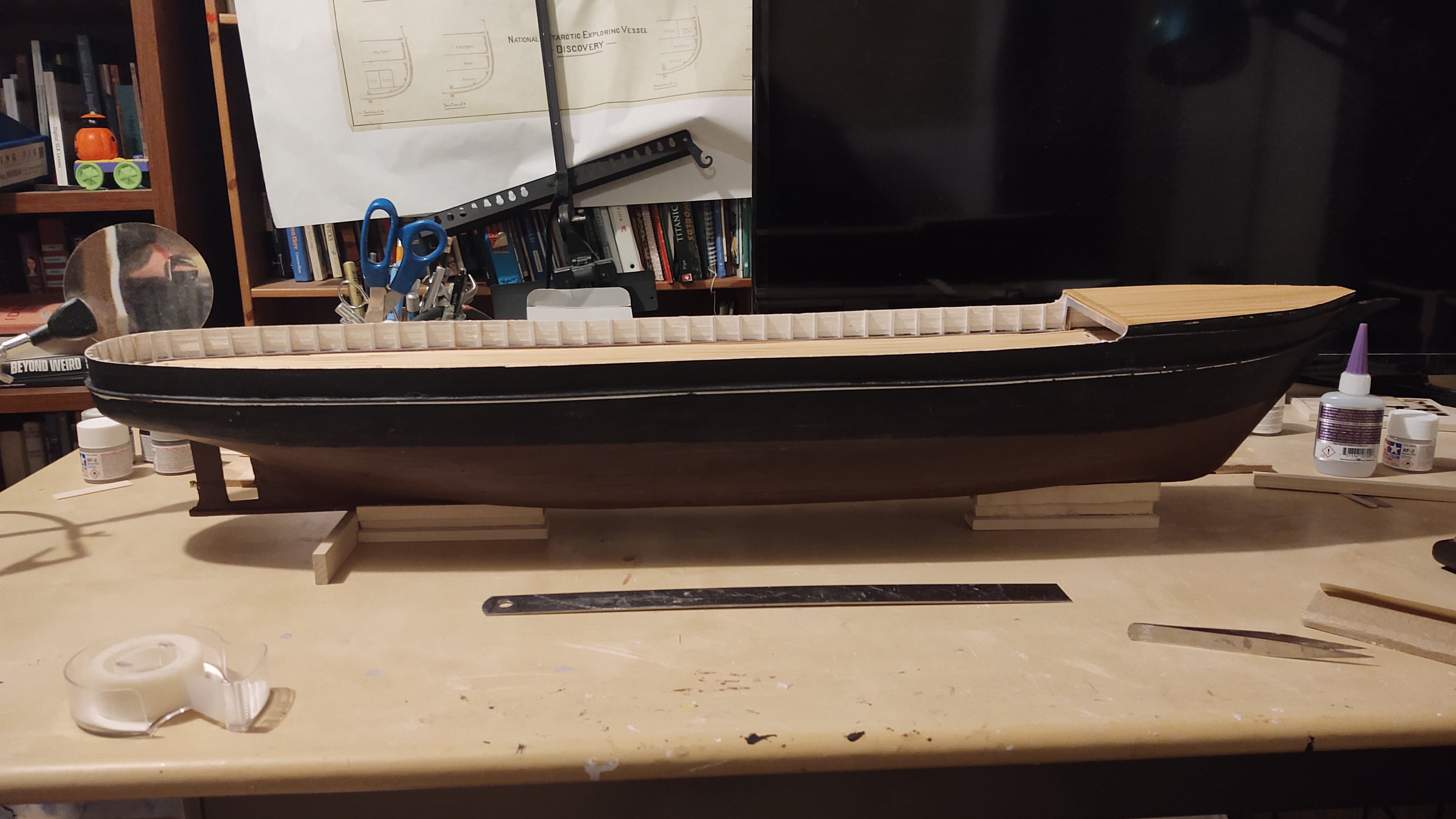
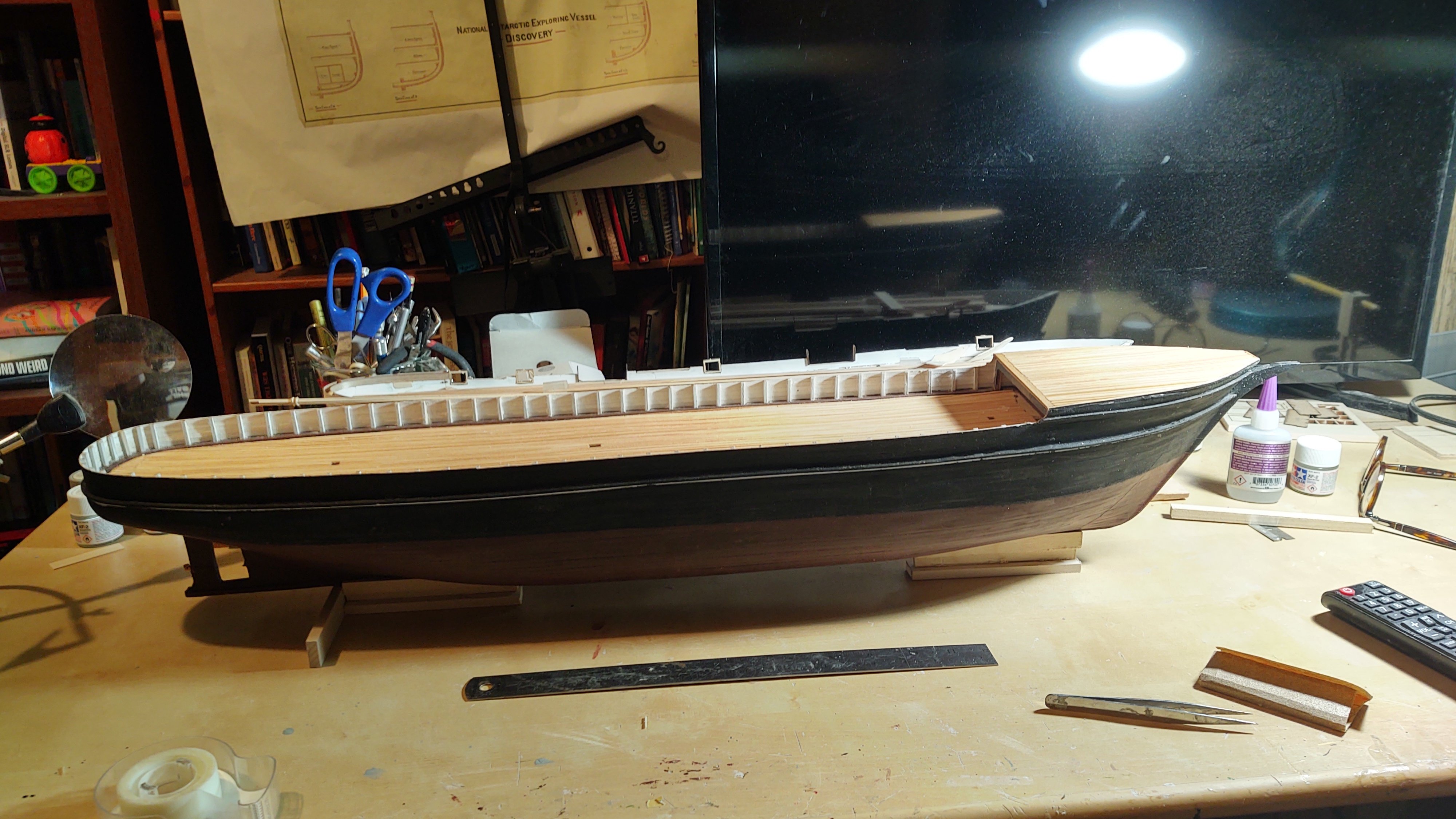
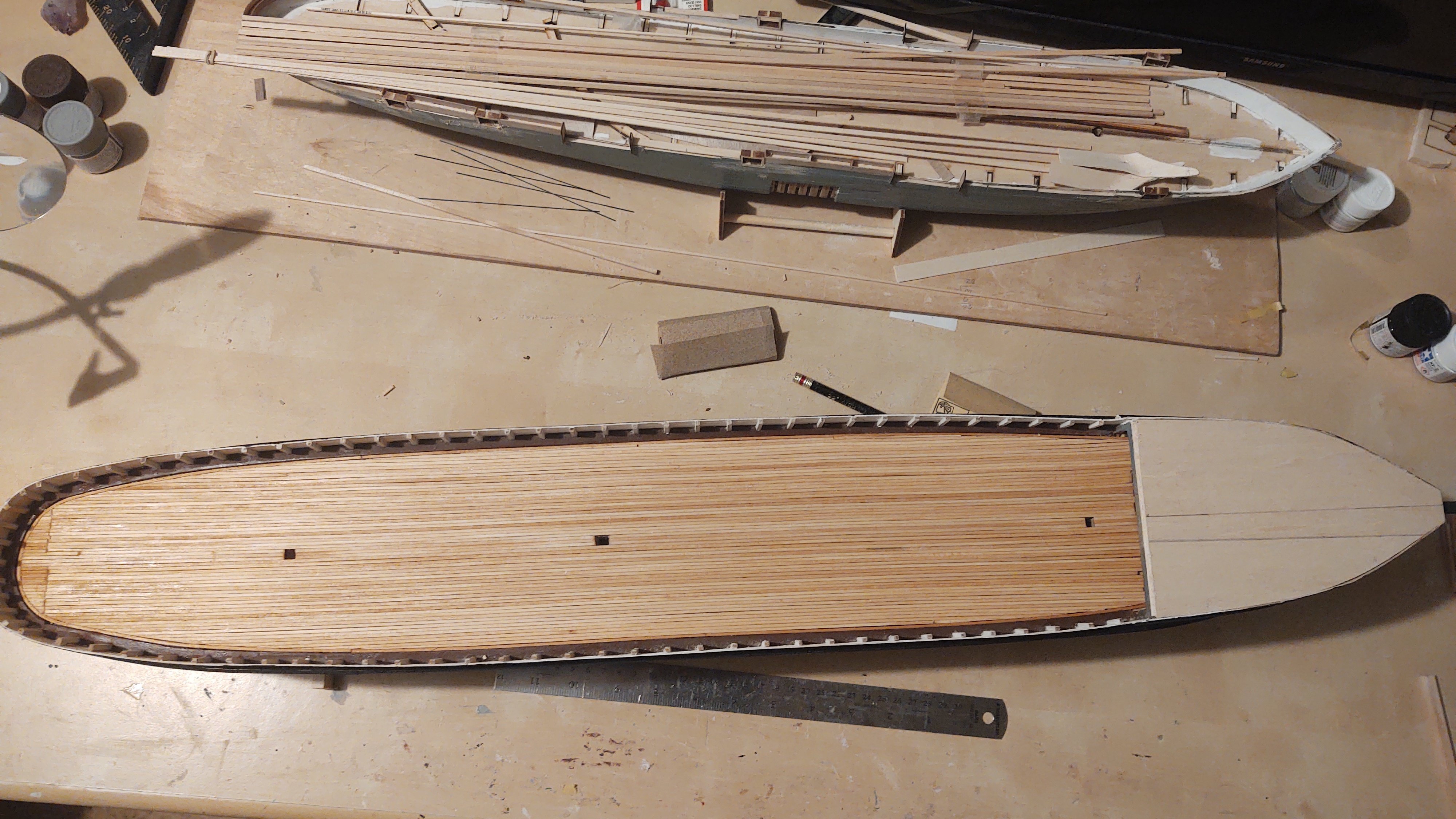
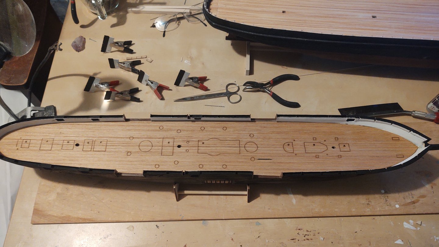
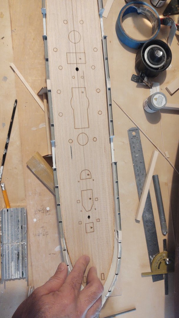
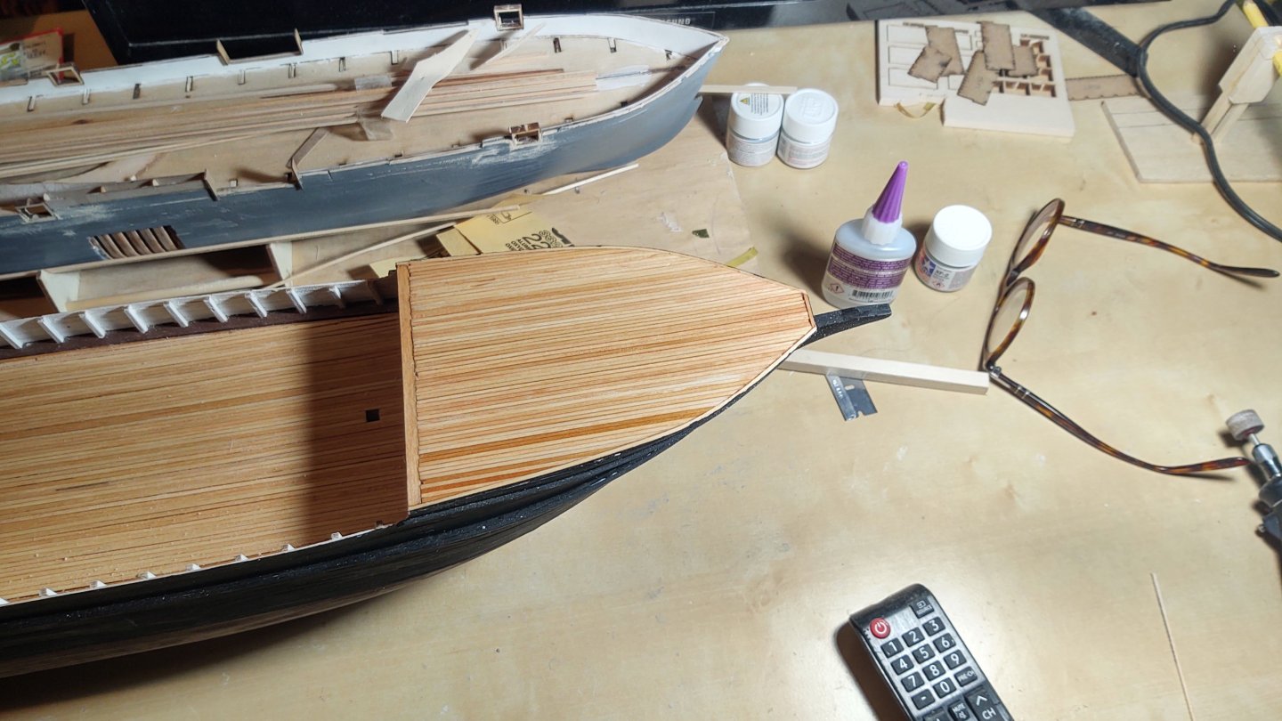
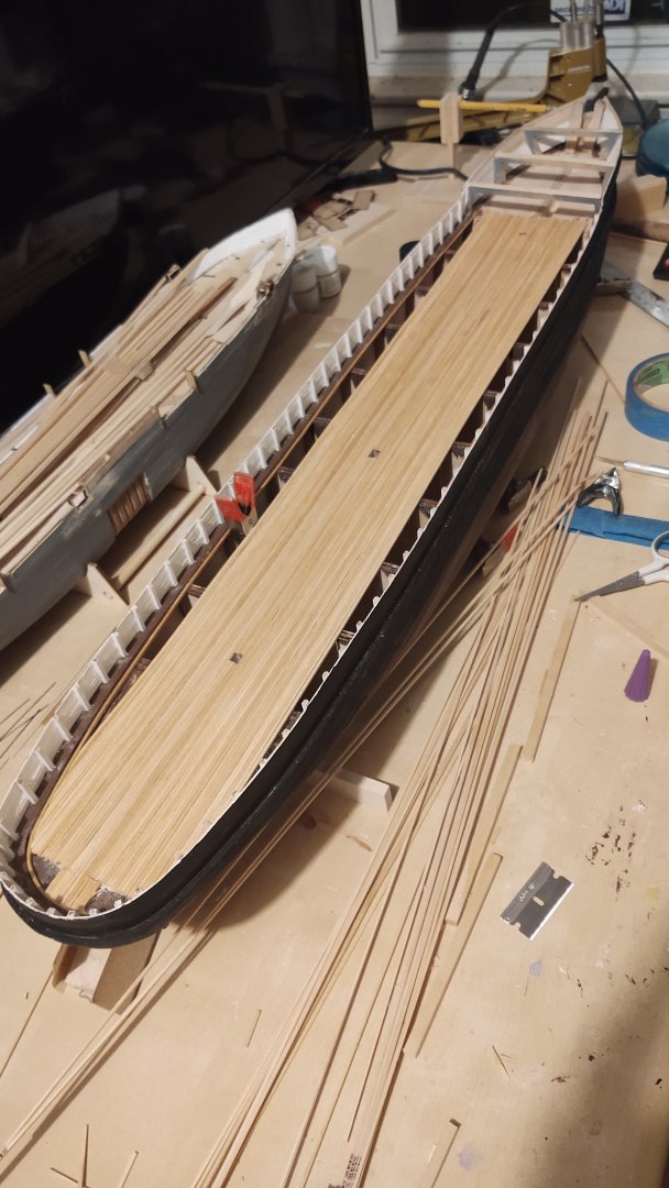
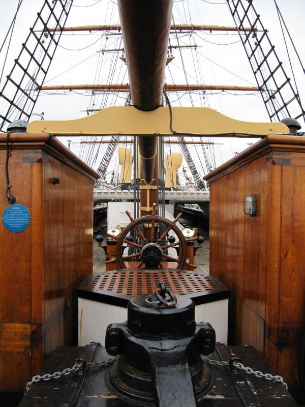
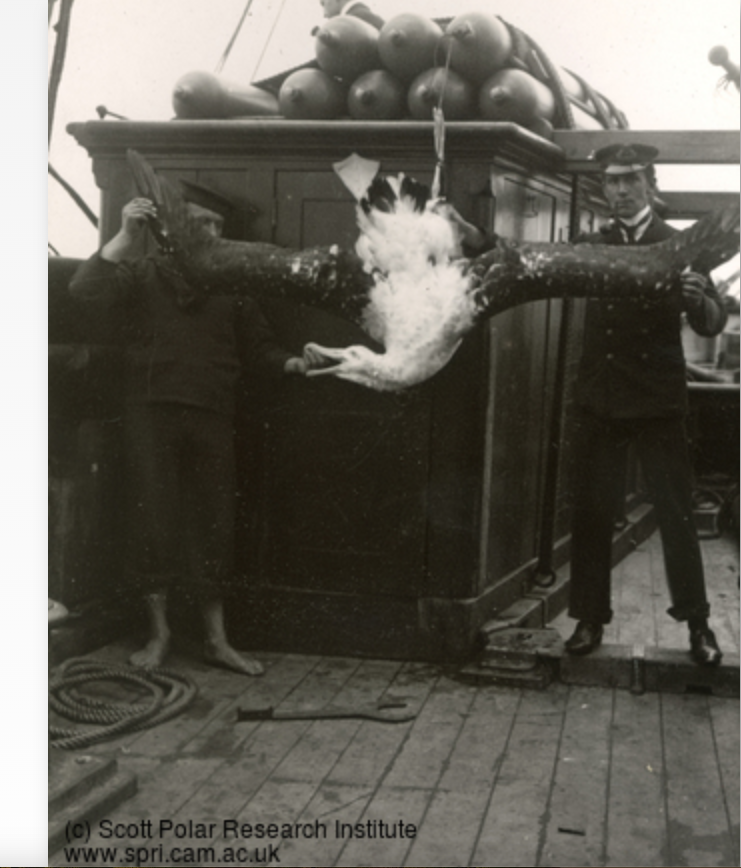
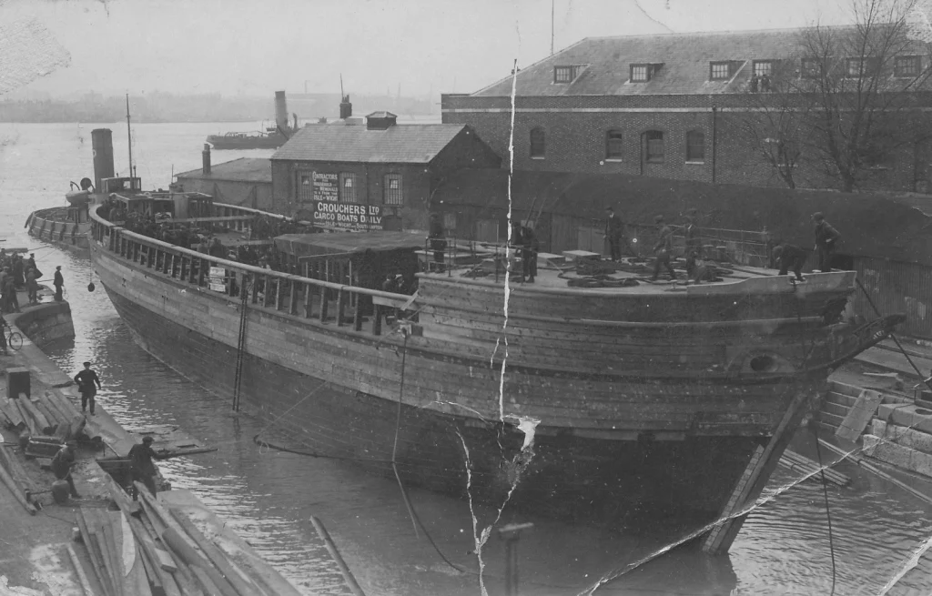
Thanks Rick! Well, a bit of an update. I've put the main deck planking on. As I mentioned, the junction at the stern is basically in a single joint, but it's going to be covered by a monkey poop, so no one is going to see it at the stern. First, mostly done: And complete: Eagle-eyed observers will note that I fitted a subdeck on the forcastle. I will glue that in place once I've set up the mounting point for the bowsprit and a couple of anchor points for the lower main forestays (which annoyingly mount inside the closed forecastle), and then will put the forecastle deck in place. As an aside, there are two doors into the forecastle from the main deck, which I will not be installing until after the standing rigging is in place, as that is how I intend to get to the forestay anchor points. Given the ship's current state, I thought I would share this one picture from Dundee Heritage Trust. It's of the Discovery in 1923, as she was going in for a refit prior to becoming an oceanographic vessel (and in many ways becoming the ship she is today). I'm pleased that there is a certain resemblance here to the model. I've started thinking about the deck furniture and this has got me deep into questions about how much to trust various sources, and specifically the current ship. As I've shown before, the plans have two deck houses in the stern that butt up against the monkey poop. Between the deck houses are the access port so that you can repair the prop, and the rudder post. Here is a picture of the starboard deckhouse (and a giant albatross) (from the Scott Polar Research Institute) Note a couple of things here. The deckhouse runs right up to the main rail and has doors on the forward side. You will note the officer standing on a rectangular metal conduit - that is the path for the chains that operate the tiller. You will also note that there is a lot of open space. By contrast, here are some pictures of the ship today (all from Wikipedia). Looking forward: And looking aft: The deck houses are smaller, have no forward doors, are closer together (it's jammed up against the access point for the screw, and the steering chains go to the outside of the deckhouse, not the inside) and do not touch the main rail. Bottom line is that as nice as it is to have the real ship around, about the only thing that can be trusted is what is shown in that reconstruction photo above - the hull. Everything else is going to have to come from plans or photos (and ones from 1901-1904, not ones after the 1923 refit). Which is okay, I just need to keep reminding myself. As always, thanks for looking in and the likes. Regards, George


-
Jared, You are really flying through the rigging process! Looking great! Regards, George
- 431 replies
-
- 1
-
-
- Flying Fish
- Model Shipways
- (and 2 more)