

rdsaplala
-
Posts
602 -
Joined
-
Last visited
Content Type
Profiles
Forums
Gallery
Events
Posts posted by rdsaplala
-
-
Splendid serving-work on the shrouds, Andy, they look great

-
San Ildefonso is looking great as always, Sjors, your modified stern looks really top-notch, and wow! that sure is a lot of cannons, beautiful work my friend
That's a very nice set of tools you have there too, really cool!

-
No prob TJ, glad to be of help, very nice diagram you have there, thanks for sharing
In conclusion, the taffarel capping rail arrangement looks more or less like the drawing in the link below:
http://modelshipworld.com/uploads/monthly_07_2013/post-256-0-03293300-1373179259.jpg
-
Thanks Druxey, I re-checked the inner railing supporters and they indeed line up with the pillars between the lights.
Thank you so much again for the help
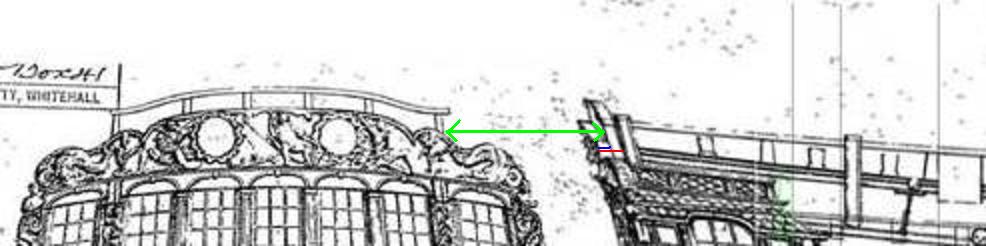
Thanks for sharing your diagram TJ, you've made a good choice in going with the blue width, you could use the Minerva picture above as reference on how the overall arrangement looks like at the front, it will be more or less like the drawing below:
-
Thanks, Druxey, I will go with your advice and go for the blue width.
One more question, if I may:
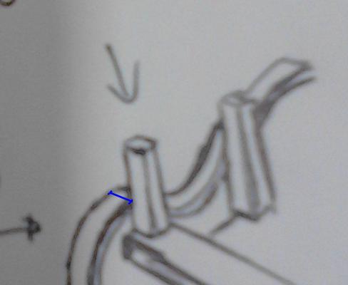
Based on the picture below, am I correct in interpreting that the structure immediately forward of the taffarel is actually the upper extension of the stern frame? (green arrow).

Thanks again for the help.
-
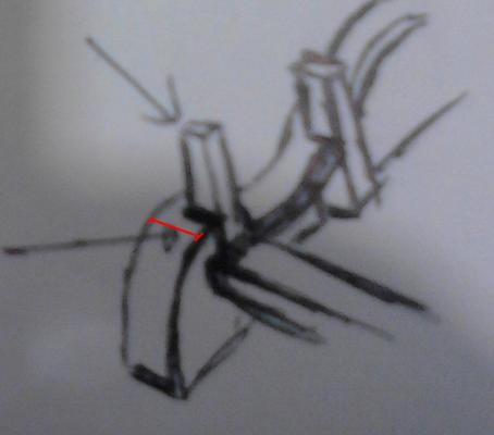
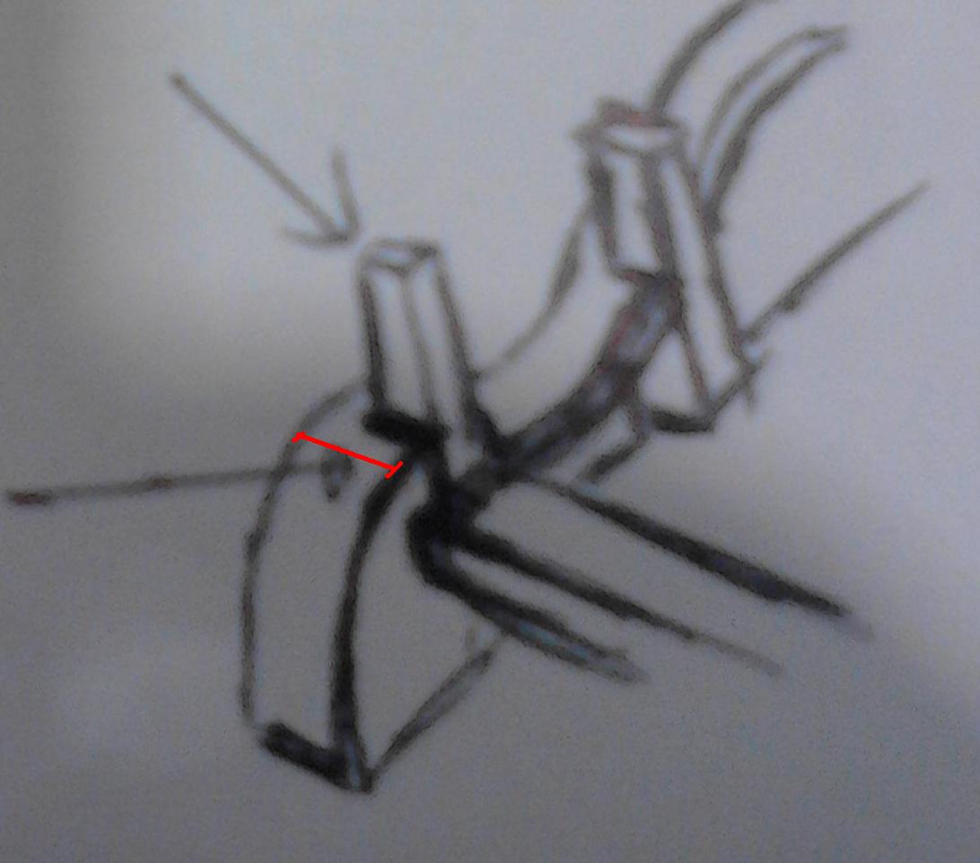
Hi TJ,
Thanks for the clarification, pardon me as I initially thought you were referring to the top-most rail above the stern frames (green line).
I'm afraid the capping rail for the taffarel seems to be a bit more complicated to interpret.
Based on page 287 of TFFM vol two, as well as majority of the contemporary models I've seen, the capping rail width should extend up to the stern timber (red line) making it more than 7mm at 1/48.
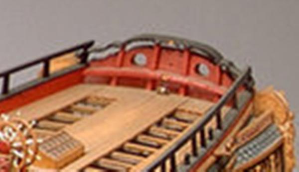
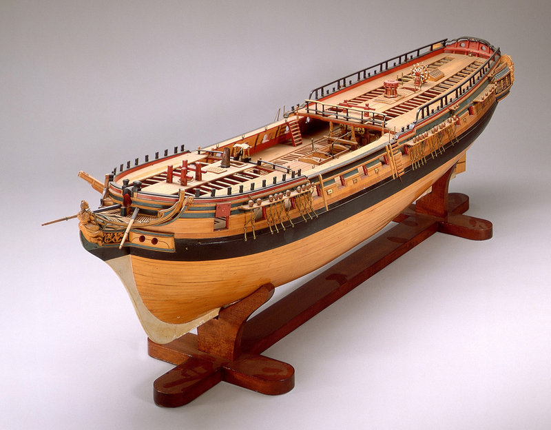
On the other hand, based on the Triton draught, as well as the contemporary model of HMS Minerva in the picture below, it appears that the fore to aft width should be the blue line(4mm):

To be sure, I made an inquiry at the research section:
http://modelshipworld.com/index.php?/topic/2796-tafferal-capping-rail-width-question/#entry76306
Hopefully, some of our more experienced members can clarify this. Will let you know once I get a definitive answer.
-
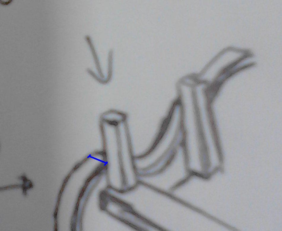
Hi Guys,
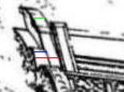
I'm currently working on a 1773 English frigate plan and I'm having some difficulty in deciding if I should follow the red line or the blue line for the width of its taffarel capping rail (see picture below):
Based on TFFM vol 2, the rail's fore-aft width should be the red line in the draught, reaching up to the forward border of the stern timber, as seen in the picture below:
However, on the draught it appears that the width is only the blue line, and does not extend beyond the aft edge of the stern timber (see picture below):
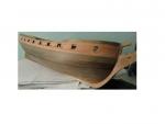
Nearly all of the contemporary models I've seen support the first drawing (red line), but the contemporary model of HMS Minerva in the link below seems to support the second drawing (blue line):
http://s3.amazonaws.com/magnoliasoft.imageweb/nmm/supersize/d4842_2.jpg
As seen in the close up below, Minerva's taffarel capping rail does not seem to extend up to the stern timber:
What do you think guys? Red or Blue?
Thanks very much in advance.
-
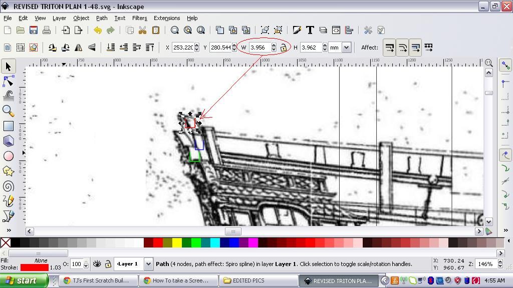
Hi TJ,
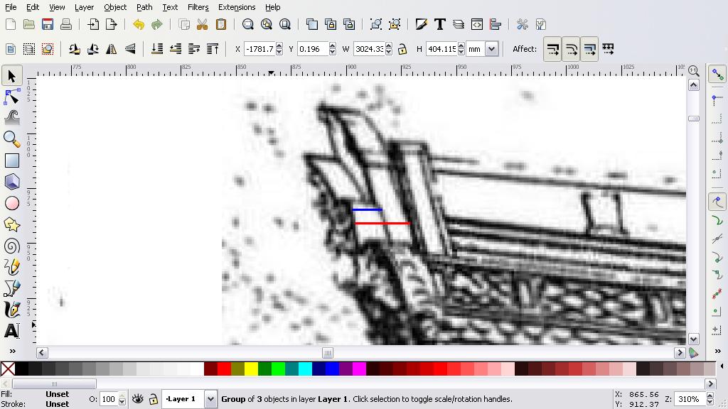
4mm at 1/48 scale seems just about right, based on my measurements from the 1/48 draught I'm working on (see links below):
http://i1182.photobucket.com/albums/x452/rdsaplala/height_zps12abc8a0.jpg
http://i1182.photobucket.com/albums/x452/rdsaplala/width_zps448a88b0.jpg
As seen in the second picture, it appears that this particular rail should have just about the same fore-aft width as the actual taffrail (green) and is just a fraction of a mm wider than the stern frame (blue).
Steel probably gives the exact dimensions, unfortunately, I don't have a copy of this contemporary reference so I just rely on the draught corrected for vertical and horizontal distortion for my measurements

-
Hi TJ,
You've done a marvelous job on your Triton, she's looking great. Regarding the dimensions of the rail atop the tafferal, one easy way is to take the measurements directly from the MSW outboard profile drawing, which is very close to the original draught based on my comparison.
I'm afraid the dimensions provided in TFFM will not be applicable to Triton as she is a different ship altogether. If you want maximum accuracy, perhaps you could inquire in the research section if someone with access to Steel or Shipbuilders Repository could give the dimensions for this particular part on a 28 gun frigate, circa 1773.
-
Happy birthday, Mark! May you have many more happy birthdays to come, my friend


Wow! Licorne sure has some lovely lines, a testament to your excellent work
Thanks for sharing that interesting cross section, those 18th Century French Shipwrights sure have a thing for aesthetics, it seems that after the step caused by the black strake (?), all the strakes, including the wale blend so smoothly together, it seems to be quite a challenge, but I have no doubt you will pull it off beautifully
-
Hello Dave,
Welcome to MSW as well as to the "Swan Class Builders' Club", there are plenty of Swan Class builders here to help you along the way
Very nice work so far, your bulkheads are coming along very nicely. Just a slight note: the bulkhead extensions at the forecastle and quarterdeck are a bit fragile and can snap especially during planking, you could protect them by temporarily taping their corresponding deck beams (see pic in the link below):
http://s1182.photobucket.com/user/rdsaplala/media/MSW/msw031Medium.jpg.html?sort=3&o=40
-
Don't worry, Andy, I think the calamity has passed and the worst is over
Guys, let's get back to work and start the nuts rolling, oops I mean the balls rolling, yikes, pardon me, I mean let us proceed accordingly

OK, I will sneak back to my cave now

- lamarvalley and Shazmira
-
 2
2
-
A disadvantage is that it tends to be difficult to bend.
I think bending won't be needed when you're making bulkheads, in fact, that's exactly what you're trying to avoid when it comes to bulkheads.... we want them to be stiff and durable so that they are not deformed or damaged during planking, hence retaining the lines of the ship.
-
One other advantage of plywood is that it has several wood layers with grain running in opposite directions, making it much tougher compared to using solid wood.
-
Hi Andy,
Just catching up, belated Happy Birthday!
Wow! Peggy is looking fabulous, top-notch job as always, Sir!
-
Thanks Christian, I fully understand your situation on prolonged shipping times.... in here, shipments from the UK generally take more than a month to arrive. If not for my regular following up with our postal office, my plan probably wouldn't be here yet.
Anyway, I am pleased that your plan is already in the post, I am looking forward to your work on these plans
-
Hi Christian,
I'm pleased to know that your NMM Plan will arrive very shortly, I've been examining my hard copy of the plans as well the smaller soft copy by using David Antscherl's articles on drafting as well as interpreting Admiralty plans and identifying/correcting distortions and it appears that both plans have very minimal horizontal distortion. I have yet to check them for vertical distortion, but what I did notice in both plans is that the baseline to top-timber distance of the sections in the body plan, do not match the top-timber heights of their counterpart sections in the sheer profile.
As seen below, taking the foremost section as an example, it appears that the toptimber height of this section (red line) in the body plan is higher when compared to its top timber height in the sheer plan (don't mind the juxtaposed colored plan):


Could you verify if this is also the case in your plan when it arrives?
By the way, did I understand correctly that you will be drawing some Plank on Bulkhead (POB) plans?
If yes, it would be great if you could share it here for the benefit of POB builders like me

-
Magnificent planking work, JP, finish looks superb too
-
Ah, there we have it, another addition to the family, top-notch work on America, Popeye, she's a real beauty!
-
Beautiful work on the galleries, Ray, they look great.
-
Good choice on taking a break from the Mirage, Sjors, everything will come along more smoothly when you return to her
-
Splendid work on the Lockers, Danny
-
Beautiful work on the head panels, Anja, I love the hull colors too
Don't worry about the darkside, you're actually practicing it now with your excellent modifications
-
Thanks, Grant, I think I'm stuck mostly in a "gray area" rather than the dark side, as I plan to scavenge kit parts for most of my fittings


HMS Vulture 1776 by Dan Vadas - FINISHED - 1:48 scale - 16-gun Swan-class sloop from TFFM plans
in - Build logs for subjects built 1751 - 1800
Posted
Beautiful work on the stern details as well as the gun carriages, Danny, and those gun barrels are 100% eye candy, really cool