

rdsaplala
-
Posts
602 -
Joined
-
Last visited
Content Type
Profiles
Forums
Gallery
Events
Posts posted by rdsaplala
-
-
Splendid work on the taffarel, TJ, very clean and precise

-
Hi Ben
Thanks for dropping by, as well as the kind words, I appreciate it
With your excellent work on Echo and Confederacy, I'm sure you'll do a wonderful job on your next scratchbuild project

I'm pleased to know you're drafting some plans for the US Brig Eagle, I once saw some line drawings of a certain US Brig Eagle, circa 1814, and I was amazed at her slick lines.
-
Splendid work, Mitsuaki, she's looking great!
-
Thanks, Grant, I hope it also works out well for the new hull that I'm currently drawing, if it doesn't, at least I still have this one to go back to
-
Hi David,
Just catching up with your build, she's coming along nicely, I will follow with interest
-
Hi Aldo,
so you´re´also working on the "Pegasus" but from the Amati kit. I found this quite expensive and therefor started with the plan the etched parts, the nice Little resin namegiving gallion figure. Purchasing wood, paints, glues, tools, etc, there also sums up quite a lot for me as well. Usually I do not build from kits, but since I came across this wonderfull Forum and having a good built model in mind that bares all my intended specialities, I found so many insperations from the fellow modelers build-logs in the Forum, so I got started in April this year. Builders that prefer to stick to the kit may find some Features strange, but that is the spice in the soup isnt it ? My building -log is nearly being edited and updated daily.
How far did you get to date
Nils
Wow! you build fast, Nils, I really envy you, I started my work almost a year ago and I've only gotten as far as planking the outside of the hull.
Very nice details there, she's looking great.
-
Aldo,
Excellent work. And it sounds like an excellent plan you have for building using a mixture of your draughts and MSW draughts. Just curious, were you able to sort out the problem with the stern being off? The 'bump' as I recall?
Thanks for the good word, Mark
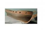
With regards to the "bump", it appears that the aft bulkheads I made using the "as proposed draught" have addressed this, based on the relatively fair run of these temporary battens:


Since the body plan of the "as built draught" I'm currently using are basically spot on with the "as proposed draught" that I previously used, the new bulkheads I'm drawing will hopefully also create a fair hull, but I'll know for sure once I build up the new hull... I'm keeping my fingers crossed
- mtaylor and Blue Ensign
-
 2
2
-
Very nice work so far, Dave, she's coming along beautifully
With regards to your questions on the deck planking, I checked the 1/48 upper deck planking drawing on my TFFM II and noted the following dimensions (reduce these to 75% for you kit's 1/64 scale):
Width of King/Central Plank and the three planks immediately on each side of it=7mm
Width of the rest of the planks outboard of the above 7planks=6mm (except for the 4 outermost planks, which are arranged in top and butt fashion)
Plank length is variable, about 120mm on the average
Planking appears to be 3-butt shift (three planks in between parallel butts)
Hope this helps.
-
Nice work Aldo. Good to see an update from you. Looks like you've put a lot of work into getting this "right" - although that is always a relative term! So when does sawdust start to make an appearance?
Thanks for the good word, Grant, just a dozen more bulkheads to go, and the workshop will see some action once more
My previous plan was to purchase a copy of Steel and perhaps the applicable establishments/ specifications to get the scantlings for redrawing all the fittings... lately however, I started to feel that drawing is just not as fun as building, so I decided that I will just remake the centerboard and bulkheads from the NMM Draughts, but use the rest of the provided plans for everything else... I guess I'm too lazy to go the whole hog after all
-
-
Hello Nils,
This is a very interesting project you're working on, I will follow with great interest
-
Time for some update, I'm still fiddling around with the computer doing my CAD-work, progress is slow as I am a "dinosaur" with almost zero knowledge on computer stuff

Anyway, I've been applying the principles I learned regarding Admiralty draughts and identifying and correcting distortions.
One important fact is that Admiralty draughts almost always have distortion due to the relative instability as well as the age of these materials. It's just a matter of determining how much distortion these may have. Distortion has many forms but the ones I find easiest to catch are horizontal and vertical distortions.
The severity of horizontal distortions may be determined by measuring "10 foot sections" in fore-, midship, and aft-portions of the draught's scale ( the ruler-like drawing beneath the profile drawing).
In the case of the 1/48 Triton draught, here are the measurements:
Fore-portion=63.5mm

Midship portion=63.7mm

Aft portion=63.5mm

I proceeded further to measure the rest of the "10-foot" sections along the length of the scale and I've found that the length variation ranged from 0.1 to 0.2mm.
This basically gives a very small horizontal distortion of only about 0.16 to 0.32% in the draught.
The amount of vertical distortion may be determined by checking the depth in hold of the ship, again, the NMM Triton Draught seems to have very minimal vertical distortion.
So, with very minimal distortions, it appears that I may yet get away with a direct trace of the lines instead of having to do some tedious redrafting

I did notice a slight issue, and that is the the top-timber heights of each specific section in the profile does not match the top-timber height of its corresponding section in the body plan :mellow:
Taking the foremost station V as an example, it can be seen that top timber height of V in the body plan (red line) is greater than its height in the profile (see below)
Top-timber height of Section V in body plan

Top-timber height of V on the profile:

This however is a minor issue, as based on my correspondence with Druxey on the Swan Class draught, I have learned that there is an easy fix to this difference in the top-timber heights between the profile and body plans (thanks for the help on that matter, Druxey
 )
)This is solved in two ways, one method is to use the top-timber heights on the body plan to create a new top timber height on the profile, and the second approach is to nudge the sections in the body plan so that their top-timber heights follow that on the profile.
I decided to use the second approach of following the top-timber heights in the profile since I will be using this profile for taking off all my vertical measurements

I also had another pleasant finding when I placed the 1/48 NMM Draught alongside the MSW 1/48 profile and deck plans:

As seen in the above picture, the overall length (red lines) and mast positions (blue lines) of the MSW inboard profile very closely match those of the NMM draught.
Furthermore, a side by side comparison of the NMM Draught with the MSW deck plan in the picture below shows that their mast positions also perfecty match. The same is true for the positions of the deck fittings.

Conclusion, it would appear that even if I make a new centerboard and bulkheads from the NMM draughts, I could still use majority of the MSW plans do determine the dimensions and placement of my fittings thereby saving me a lot of work
Lastly, I have already made some patterns for my deck camber and started work on drawing my bulkheads, so far, I've already completed 2 so I only about a dozen more to go


-
Beautiful rigging and masting work as always, Peter, the mast looks good as new after your repair
-
Thanks, Grant, I'm still stuck to the computer doing some drawings, the good thing is that I am able to sneak some CAD-work while on break at the work place
-
Very smooth and clean planking work, Popeye, I love it
-
Hi Popeye,
Sorry to hear about your run with bad luck as of late, but as Mark says, when it rains, it pours, so hopefully, it's now good luck's turn to pour in
I think the beautiful rigging work you've done will inspire lady luck to smile upon you very soon my friend, top-notch job as always
-
Stunning work on the cannons, Danny, and thanks for sharing your jigs and techniques at mass producing them, simply ingenious
-
-
Amazing planking and treenailing work, JP, and the wale looks very nicely done too, don't worry about the littles oopses, they'll barely be seen once all the fittings and rigging are in place
-
-
Beautiful work, Sjors, simply beautiful!
-
.....Aldo, thank you very much. Have you been able to manage any hobby time lately?
Andy
Thanks, Andy, I'm currently glued to the computer redrafting some new bulkheads for my Triton so it may be a while before my workshop sees some fresh sawdust.
Very nice and clean serving work, Andy,based on this excellent job, I can predict that you'll master this new technique in no time
-
Top notch work as always, Ray, the coppering and quartergalleries look fantastic!
Edit: Oh my, I think I need new glasses as I have somehow missed the others' posts,
Happy Happy Birthday, Ray, this calls for some champagne!

-


Triton 1/48 by The Learner
in Build Logs for the Full Hull Version of HMS TRITON
Posted
Beautiful work on the frames, Guy
With regards to your question on the position of the bollard timber, based on TFFM, it appears that its fore edge should line up with the inner border of the rabbet/groove for planking (green arrow) then once close to the stem head/top portion of the stem, its forward edge moves further forward and lines up with the outer border of the rabbet then continues upward to form the knighthead ( blue drawing).
I measured the 1/48 plans and the top portion of the bollard timber/knighthead is about 22.8mm above the stem head (red arrow/circle).