

rdsaplala
-
Posts
602 -
Joined
-
Last visited
Content Type
Profiles
Forums
Gallery
Events
Posts posted by rdsaplala
-
-
-
Amazing details and paint-work, Mobbsie, that sure is a lot of eye candy

Just a small question, my friend:
Could you give some tips on how you approached building the quarter galleries? I still have a long way to go before making them on my Triton, but I am already having some cold sweats trying to figure out how I would approach these complicated structures

-
-
Thanks for the good word, Sjors and Frank, they are much appreciated

Frank, I'm pleased to know you don't see any bulges, that was my exact goal for modifying my bulkheads

-
Hi Sjors,
You're just in time my friend, here are my latest updates
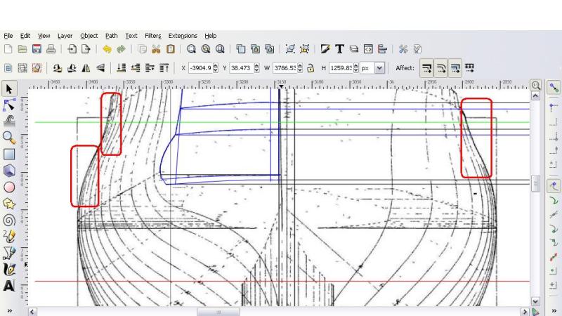
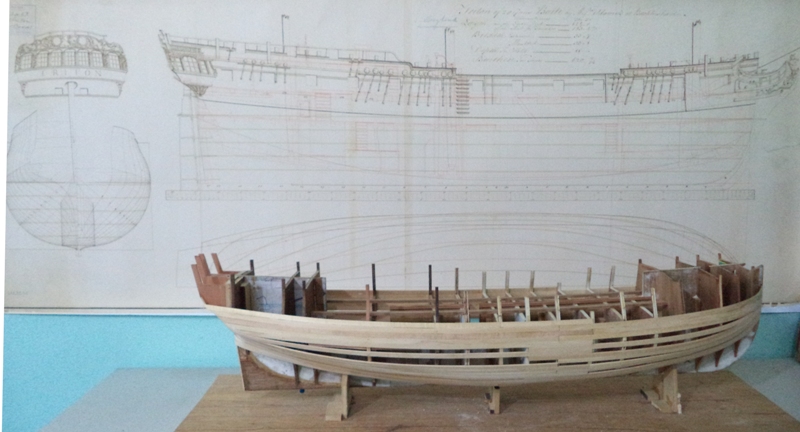
While drawing my bulkheads, I've experienced some difficulties tracing the middle-most stations as they have incomplete lines (red boxes):
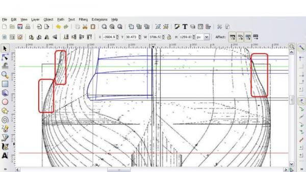
This caused some head-scratching for some time, until I recalled my previous findings:
1. The hull that I currently have has modified aft and fore bulkheads based on the "as proposed" Modified Mermaid Class Body Plan, which upon juxtaposing on CAD, is spot-on with the "as built" Triton Body Plan I am using now.
2. The deck levels and overall length of the MSW profile plan, which I used to create my centerboard were also pretty close to the as built plans.
To check for accuracy, I printed the fore and aft-most bulkheads that I drew on CAD and compared them with those on my current hull..... law and behold, they were very close indeed with a maximum difference of about 1mm in some areas.
These results, plus my hesitance to "guess" the shape of the middle-most bulkheads,prompted me to just continue working on my current hull, which is a mix of NMM-based fore and aft bulkheads and MSW-based bulkheads at the midship area.
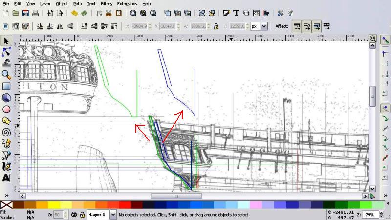
I did some final tweaking to all my modified bulkheads using the cardboard cut outs of my CAD drawings then proceeded to drawing the stern frames. I decided to make only the innermost (green) and outermost timbers (blue)... a lazy shortcut I adapted from most of the kits I have built


With the time consuming drawing-work finally done, it was time to make some wood dust in the workshop
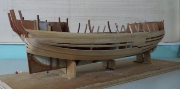
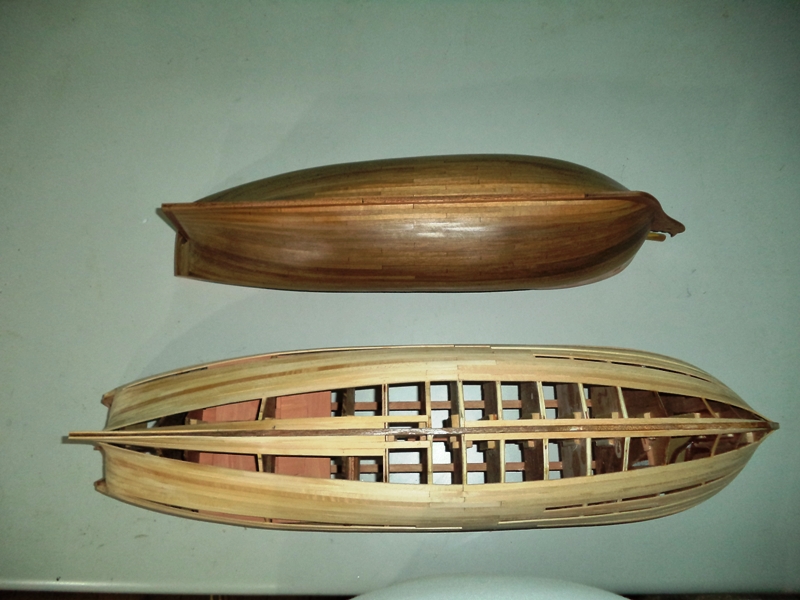
Of course, since this is an "experimental hull", I decided that I will double-plank her, starting with an initial layer of lime planks at the lower hull just to see how fair she would be.
Furthermore, since this is only the first planking, I will not strictly follow all the "planking rules" and just accept the "pointy" plank ends for now

If the hull shapes up nicely, I will give it a decent second planking, if not.... well, let's just say that there will be a lot of extra wood for cooking barbecue

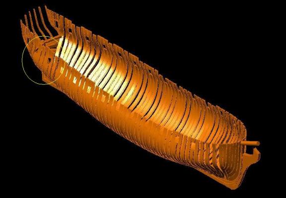
As a review on why I went through all the above intricacies, here is the "bulge" in the lower hull that had me worried hence my decision to modify my bulkheads:
Here now is my "haphazard first planking" to show how the hull is shaping up... so far no bulge is rearing its head but I'll know for sure once I'm finished
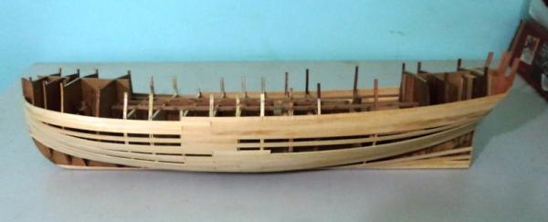
I made the extensions of the bulkheads and stern frames thicker for strength... I will trim them down to proper size once I'm finished with the planking:
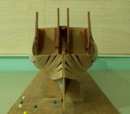
Here is my "kit-inspired" stern with only four stern timbers reminiscent of my Caldercraft and Amati kits..... note also my violation of planking rules giving rise to numerous "pointy" stealers

Sigh... each time I see my NMM Plan alongside my model, I realize that I have a loooong way to go before she even starts to look like a ship

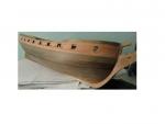
I thought I'd also make a size-comparison with my 1/64 Amati Pegasus Sloop:
They seem to be almost the same size.....
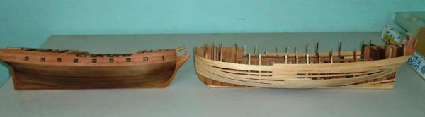
.... well, maybe not exactly the same size

That's it for now, my next update will be upon completion of the lower hull first planking, during which, I will decide if the hull shape is acceptable enough to warrant some decent second planking or if it is better suited as kindling for the barbecue grill
-
Thanks for the kind words, Mobbsie, I frankly am not sure if I deserve all those compliments as I am frankly struggling to understand all these shipwright stuff and have yet to see if my "experimental hull" turns out looking like a ship or a lump of sticks
Don't sell yourself short my friend, with the excellent job you're doing to Aggy and your beautiful work on your other ships, I'm sure you will have no problem with a project like this
-
HI Aldo.... just ck'n your progress, I'm lost when it comes to what you're doing....... very interesting build you've got going. Can't wait till you start planking , your planking technique is one of the best I've seen. Looking forward to it!!!
Frank
Hi Frank,
Thanks for dropping by and the kind words my friend, they are much appreciated
I too am excited to plank this "experimental" hull, I'm keeping my fingers crossed, and hoping that it still ends up looking like a ship when I'm done
-
Thank you so much for the link, Guy, I'll give it a try
-
Hi Popeye,
I'm using Inkscape for my drawings, it has a lot of limitations most important of which is it's lack of 3D capabilities, so I still have to check for fairness manually, using the halfbread and profile, but I decided to settle for it mainly because
it's free
: http://inkscape.org/download/ -
Hi again!
Here´s where I am now... ALL the frames cut out. How I miss the laser cut bulkheads of plywood of the comercial kits!!!!.....
Happy modeling!
Daniel.
Beautiful job on those frames, Daniel, that sure is a lot of work, now the planking fun begins
-
Beautiful picture Aldo!
It really catch the effort you´ve done so far. I like the battens you have put on too. Now start the fun job for you!!
Best wishes.
Daniel.
Hi Daniel, thanks very much for dropping by and the kind words
I understand that you're also finished with your frames so the planking fun will also begin very shortly with your build -
you had mentioned this earlier.....but I guess it never clicked. I've finally had the chance to check this out........man!......I am so amazed at what your doing. I don't understand CAD at all......never tried it. you've come a long way........looks great! I've been wanting to get into something like this....perhaps with your help, I can understand more of it............maybe take the plunge down the road. count me in to be following your exploits!
Thanks for visiting as well as the kind words, Popeye
Come on and take the plunge my friend, with your excellent scratchbuilding skills and ingenuity, I have no doubt that you can master CAD in no time at all
-
A mighty fine job on those blocks, Grant, your jig works perfectly, thanks for sharing your technique
-
-
Thanks Popeye, Guy, John, Mike, and David
I deeply apologize that I did not reply earlier, and instead, I just placed "likes" on your comments as I didn't want to put my log up in front of the kit builds and mislead anyone into thinking that I have an update.
Pegasus is temporarily "mothballed" for now while I focus on redrafting and building my HMS Triton hull.
Thanks again for the friendly nudge, Popeye, I appreciate it
I'll be sure to update Peggy Sue once I finish planking my Triton
-
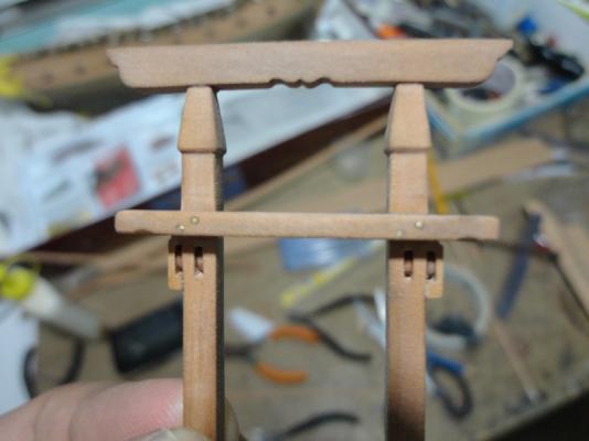
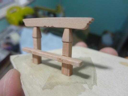
If you're working on a small scale (ex. 1/64 and below), I would recommend a scroll saw to cut the tight corners as mentioned by the others, yes perhaps you could manually cut this with a fret saw but the scroll saw has a big advantage of making the work much easier and faster.
As examples, the two gallows below were my first attempts at using a scroll saw and it was such a breeze to cut all those tight corners. Note that the gallow is only about 2 inches wide so I doubt if a bandsaw could be used to make these. Oh, I also tried doing this with a fret saw and let's just say that the results were less than adequate
:
-
Thanks for the vote of confidence, Guy
...If the bollard timbers are suspose to be longer I will recut to allow for the additional meat and length.
Thanks
Or you could proceed with your current MSW-based bollard then just add the knight's head as a separate piece once the capping rail has been completed. This may seem like cheating but, in all honesty, it is much easier to shape the knight's head as a separate piece, and once installed, no one would ever notice
-
Excellent planking work, Mark, she's looking great
Regarding the sheer strakes/chain wales, I would personally go with the contoured shape shown on the plan since contemporary plans are sort of my "default reference", plus majority of contemporary models I've seen ( of mostly English ships unfortunately) show them contoured, and most importantly, I think they look cool that way
:http://s3.amazonaws.com/magnoliasoft.imageweb/nmm/supersize/l2414-007.jpg
Sorry I can't be of much help on the gunport linings, my references also show mixed pictures on this one
-
That void indeed seems to be a bit of a predicament, Guy.
I decided to juxtapose the MSW Bollard Timber drawing (blue) with the MSW Disposition of Frame (DOF) Plan and Inboard Profile in the hope of solving this predicament, and written below are my findings:
As seen in the picture below (click on pic to enlarge), it appears that the provided bollard timber drawing does not include the knight's head in its composition (encircled in green) and only goes as high as the toptimber height (red arrow). There also seems to be a void (red circle) at the bottom of the bollard but it is not as pronounced.

Given the above analysis, my previously provided height of 22.8mm is not applicable since it is meant to be used only if the bollard timber includes the knighthead in its composition as provided for in TFFM.
Based on my retaken measurements, if your bollard timber is based on the MSW Plan, its top should only be 13.64mm high from the stem head so as to coincide with the top-timber height (see picture below):

If you already have your keel set up on a baseboard, a more accurate measurement of the top of the bollard timber is 186.53mm from the baseline/bottom of the false keel, as seen in the picture below:

Furthermore, since you are aiming for a precise location of the bollard, it should be positioned in such a way that it's fore edge is 7.68mm from the fore edge of the stem:

Just a small disclaimer, I am not working on the POF version so I cannot claim that my analysis is 100% accurate, hopefully, someone with a POF build could chime in to verify my findings.
-
Thanks for dropping by and the kind words, Guy, I appreciate it
-
Guy, the drawing I've shown is the 1/48 scale inboard profile found in the Triton downloads area.
-
Hi Christian,
Just catching up, Diana is looking great as always, I love all the modifications you've done to her, beautiful paint job on the figure, Sir
-
Wow! Splendid work, Ben, everything is very clean and crisp, at the speed you're working on, she'll be completely fitted out in no time
-


HMS Vulture 1776 by Dan Vadas - FINISHED - 1:48 scale - 16-gun Swan-class sloop from TFFM plans
in - Build logs for subjects built 1751 - 1800
Posted
Lovely work on the guns and their rigging, Danny, I love the "weathering effect" you gave to tone down the color of the breech ropes