HOLIDAY DONATION DRIVE - SUPPORT MSW - DO YOUR PART TO KEEP THIS GREAT FORUM GOING! (89 donations so far out of 49,000 members - C'mon guys!)
×


Dlowder
-
Posts
41 -
Joined
-
Last visited
About Dlowder

- Birthday June 1
Recent Profile Visitors
1,304 profile views


-
 Dlowder reacted to a post in a topic:
HMS Victory cross-section by Russ2025 - FINISHED - Artesania Latina - 1:72
Dlowder reacted to a post in a topic:
HMS Victory cross-section by Russ2025 - FINISHED - Artesania Latina - 1:72
-
Dlowder reacted to a post in a topic:
HMS Victory Cross-Section by RolandR - Artesania Latina - 1/72
-
Dlowder reacted to a post in a topic:
HMS Victory Cross-Section by RolandR - Artesania Latina - 1/72
-
MBerg reacted to a post in a topic:
HMS Victory by Dlowder - Corel - 1:98 - Cross-Section
-
Dlowder reacted to a post in a topic:
Speedwell Battle Station Kit 1752 by CiscoH - Syren Ship Model Company - 3/8" or 1:32
-
Dlowder reacted to a post in a topic:
HMS Victory Cross-Section by captgino - Corel - 1/98
-
Dlowder reacted to a post in a topic:
Speedwell Battle Station Kit 1752 by CiscoH - Syren Ship Model Company - 3/8" or 1:32
-
Dlowder reacted to a post in a topic:
HMS Victory by Pfälzer - Corel - 1:98
-
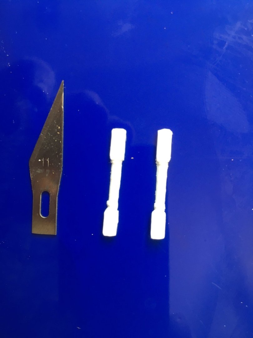
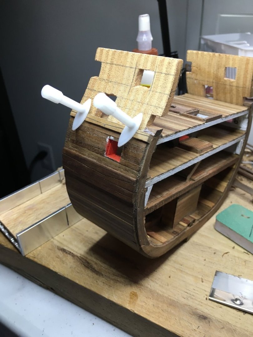
 I can't it's been a year since I updated this. I haven't worked much on the model since life's been hectic. Went on our first cruise ever one year ago. Lot of fun but the last night I started feeling rough. Got home the next day and tested positive for Covid! It took a while to get over it. Got through the summer chores and then the hurricanes hit. Lots to clean up. I've worked a little off and on but now I'm finally trying to get motivated to get back to the workbench. What I want to show today is that I am working on columns. I've tried several ways to make them using wood but I decided to try 3D printing for the first time. I put together a design and split it in half since I thought it might print better without having to have any supports. Then I could just glue the two halves together or use just a half of one if it needed to be on an edge or against a wall. My son works at the university library that has a printer I was able to use for free so I printed just one to test. I need to now try the printer at the public library to see if it is better quality. I made them long so I can cut them to length as needed. I need to do some cleanup, prime and paint. Lets see if I can attach the stl file if anyone wants it. Victory Columns.stl
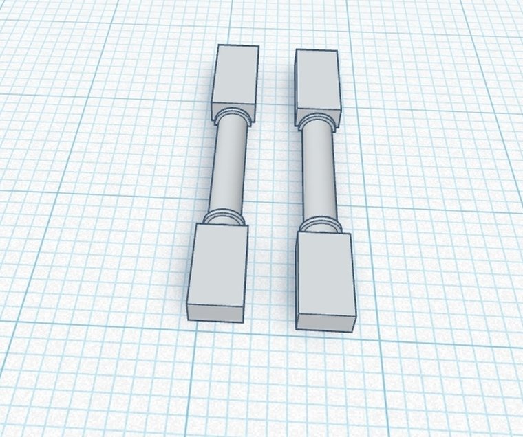

-
Duanelaker reacted to a post in a topic:
HMS Victory by Dlowder - Corel - 1:98 - Cross-Section
-
Dlowder reacted to a post in a topic:
HMS Victory by Tyguy35 - Artesania Latina - 1:72 - cross-section
-
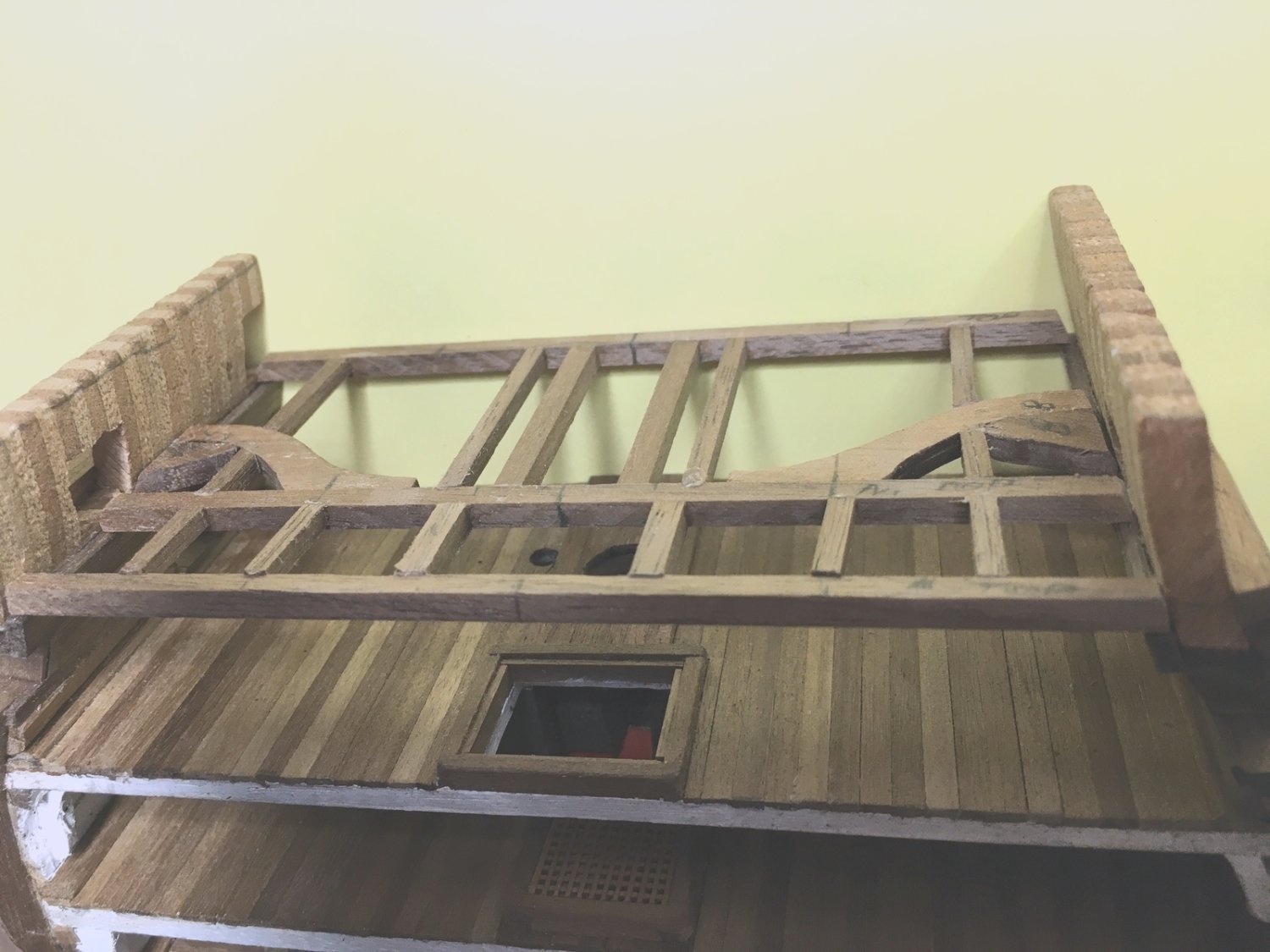
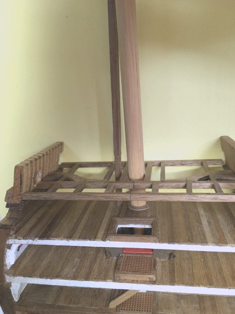
Just a quick update that I haven't given up on this. I’ve been away from this for a while. After many tests they finally found and removed the tumor that’s been playing havoc with me for the last year so now I hope to make up for lost time. I just need to remember where I was in the build. Beams for the upper deck test fitted. Like the other decks, I made this so I can slide it in and out as needed. Test fitting the main mast and what will become an elm tree pump to check for alignment and clearance between beams. Adding more structural members and planking. I cut a notch for the pump. Sliding the deck in for another test fit with the pump. I have to get the hanging knees shaped and located. Then I can slide this deck back out and finish out the middle deck with details and paint. Thanks. David


-
Good luck with your tests. I've put my build aside also while I've been getting medical tests. Hard to get motivated.
- 25 replies
-
- 2
-
-

-
- Victory
- Cross-Section
- (and 1 more)
-
Hi, from Balearic Islands, Spain.
Dlowder replied to Miguel Juan Calvo Fürst's topic in New member Introductions
Welcome aboard. David -
Welcome to the forum. David
-
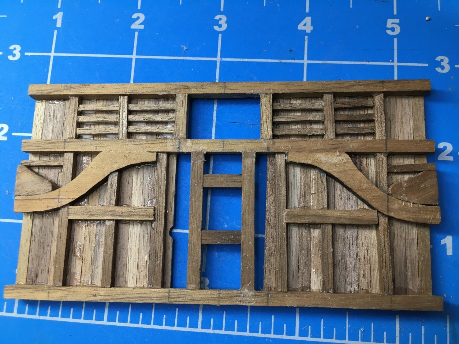
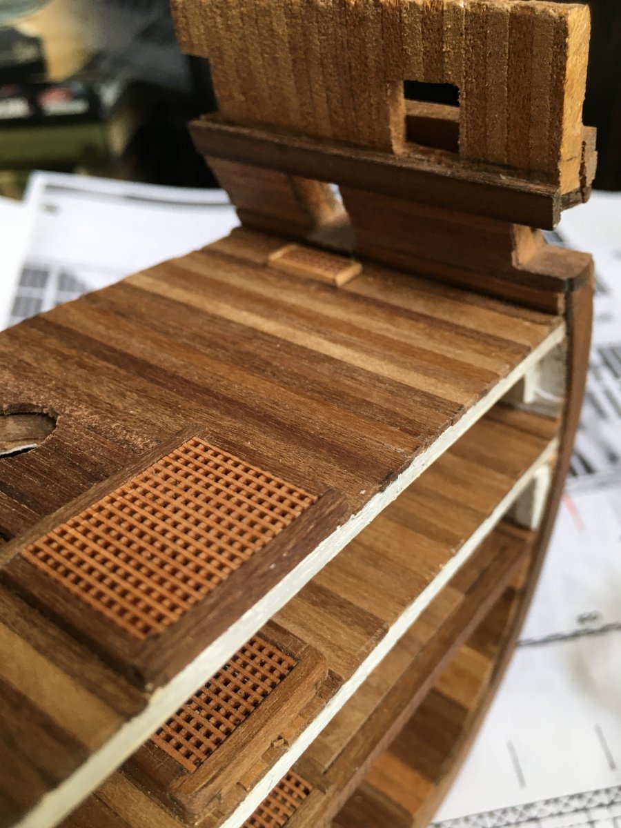
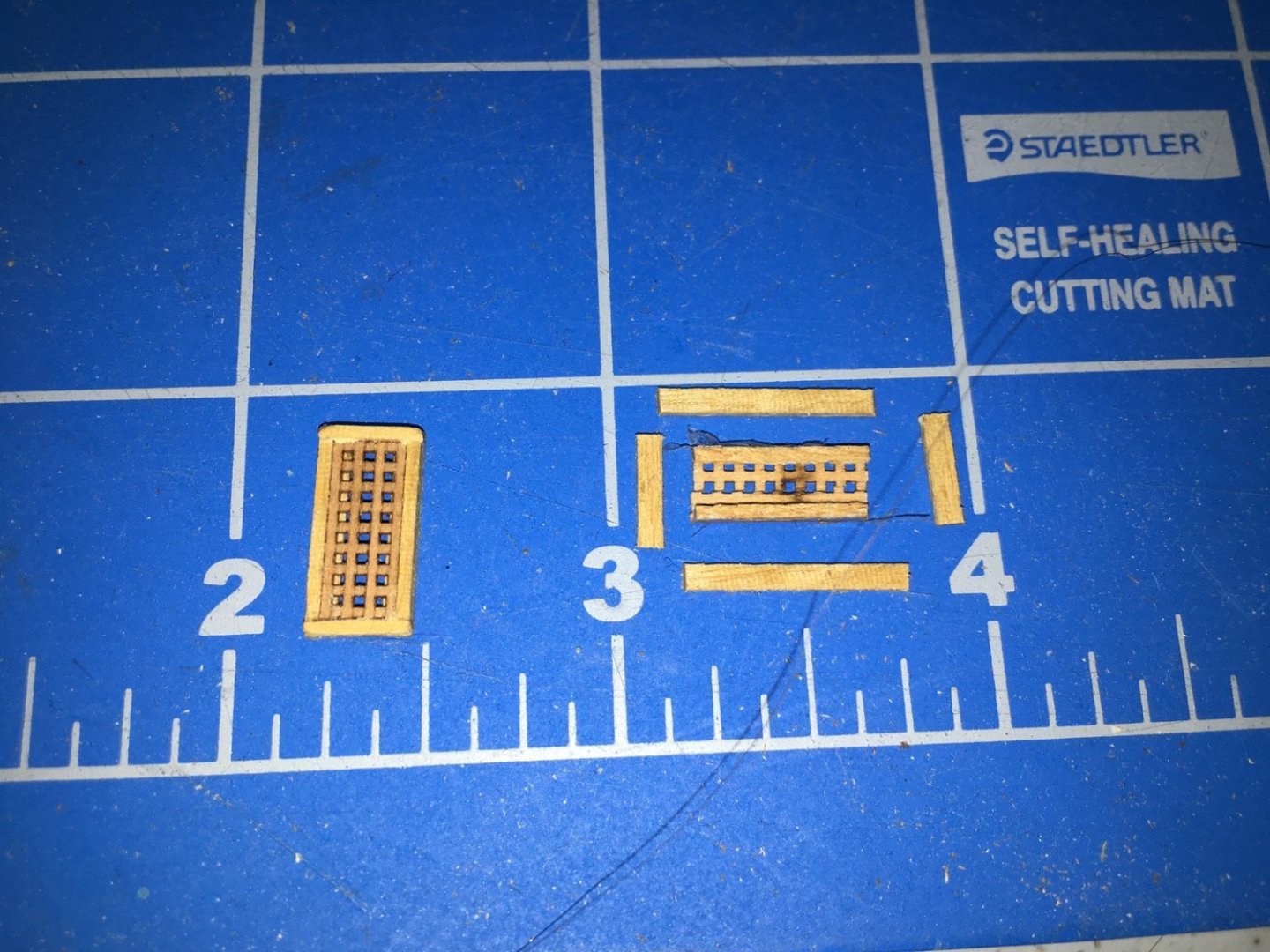
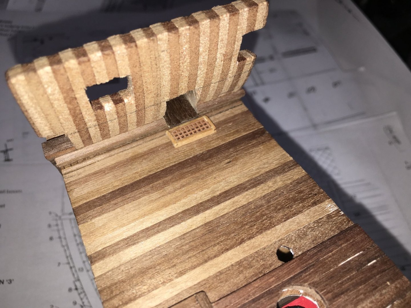
I’m back at it again. Been under the weather for a while so moving slowly on this. Plans from several sources show small grates at the entry ports so I built these using the same grate material as I used before. I’ll wait to glue them in place after I paint the deck sides. The octagonal hole in this deck is for an elm tree pump to will continue up to the upper deck. I planked up the exterior and interior with rough openings for the entry ports and the gun ports. I’ll clean them up when I add the linings. Next I'm working on the structure of the upper deck since there are middle deck fixtures that have to align with those beams. David

-
Entry Port Grates
Dlowder replied to Dlowder's topic in Building, Framing, Planking and plating a ships hull and deck
Thanks Greg. That's my original question… does anyone know how the water was drained? Would it be visible on my model or would it be hidden behind the grate? I'm going to assume that any drain point would be out of sight. I'm not trying to model an exact replica of Victory at any point in her career, I'm just trying to learn more about maritime technology of the period and replicate it in 3D. A generic ship of the line if you will. Sort of like the AISC Steel Sculpture for those engineers out there. https://www.aisc.org/education/university-programs/steel-sculptures/#9795 -
Entry Port Grates
Dlowder replied to Dlowder's topic in Building, Framing, Planking and plating a ships hull and deck
Thanks Dafi, I missed seeing the link in your post to the earlier thread. Just now read it. David -
Entry Port Grates
Dlowder replied to Dlowder's topic in Building, Framing, Planking and plating a ships hull and deck
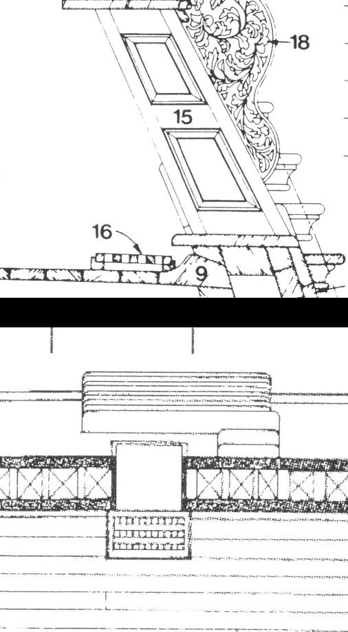
Thanks for all of the replies. I'm no expert but I still think that, even if it wasn't designed for that purpose, it served to help drain any water coming in the entry port if it was open in foul weather. Several aspects of the entry points suggest to me that water infiltration was a concern. Goodwin's “The Construction and Fitting of the English Man of War 1650-1850” has an illustration on page 193 showing an example from 1670 with the entry port having a grated platform on the outside. I see no other reason for that one to be grated than to allow drainage for better footing. Also entry ports have canopies that must be there to prevent rain coming in but in a good blow rain would still get in and need to go somewhere. I think that anyone coming in wet from the rain will be shedding water once they are on that “welcome mat” and the water will need to go somewhere. Regardless of all that, it's bound to be too small a detail to represent in 1/98 scale on my model. Thanks again, David -
I hope this is a good place to ask this. I'm looking for more information on the grates on the deck at the entry ports for my HMS Victory cross section. I have one book with two drawings. One is the deck from above and the other is a cross section through the middle of the grate. I assume that these are here to drain any water coming it but I'm curious as to how the water drains out. Is there a scupper leading through the waterway or does it run out fore and/or aft in some way that's not shown in the drawings? If there is a scupper, it seems like it would be dumping water on the steps and make footing more challenging. On Victory today this appears to be covered with a ramp on the deck to prevent tripping. The view of the outside planking is also blocked in every photo that I've seen so I can't tell if there is a scupper. And maybe I'm being too picky in worrying about this. Thanks! David
-
Just catching up with this build. I'm very impressed. David
- 208 replies
-
- 1
-
-
- kitbashing
- Woodcarving
- (and 4 more)
-
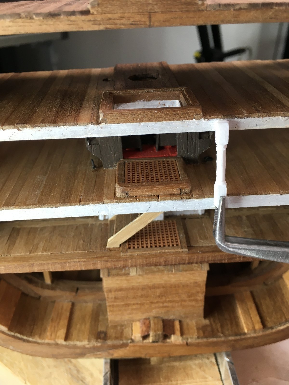
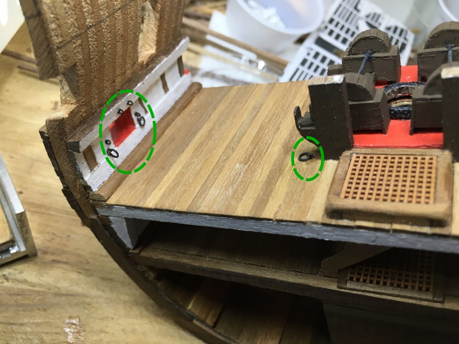
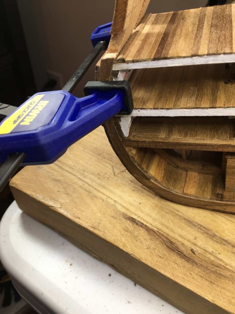
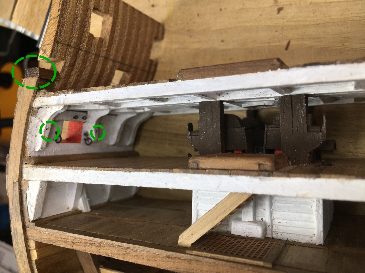
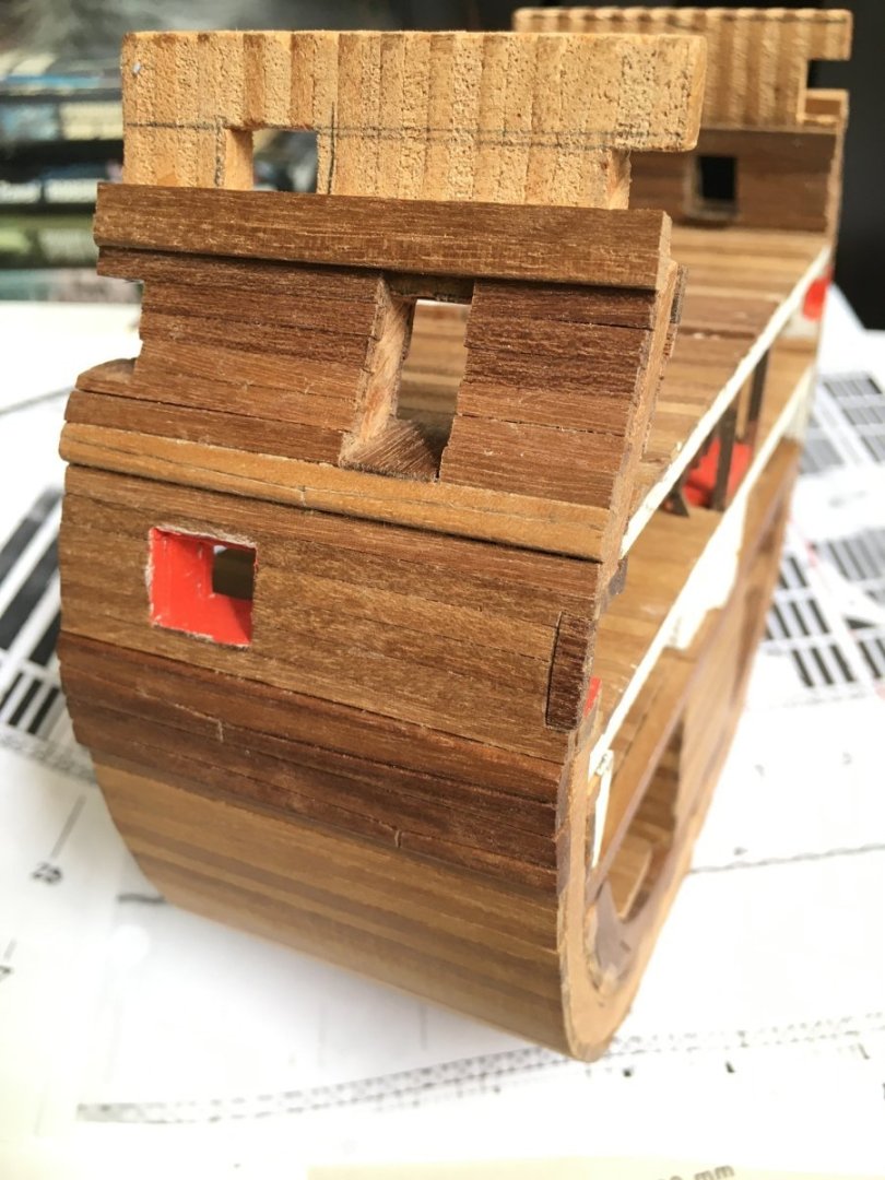
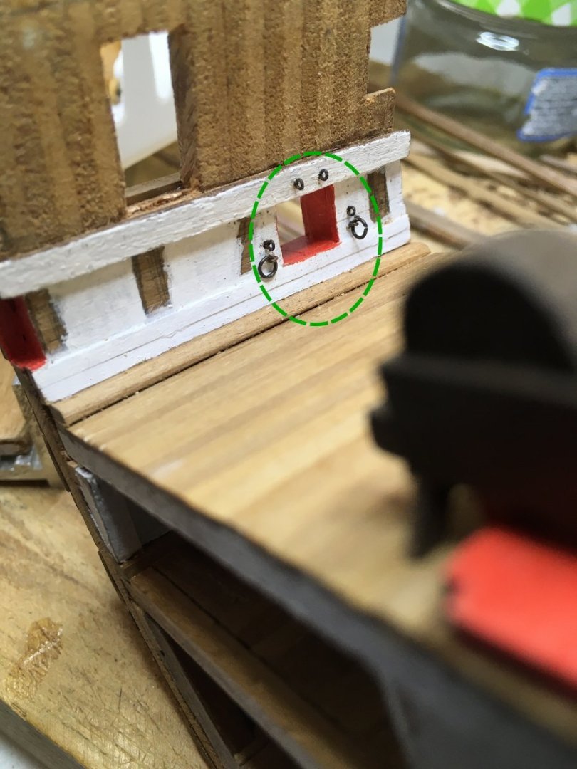
I haven’t felt up to working on this the last few months but thought I should at least update the log. I added eyebolts and rings to the ports and to the deck. I predrilled holes in the knees so I can add hardware there when I mount the guns. I installed the middle gun deck and then glued the knees in place. Before gluing I had very carefully shaped the knees to fit tightly in place but of course once I glued them in in, there were gaps where the fit was off. I mixed some sawdust with glue and packed it into the gaps before doing the touch up painting. I have an angled paint brush to make it easier to reach tight places. I added some more of the very thin walnut sheet to cover the rough kit material. I love this clamp. I also added the gun port sill. I need to increase the height of the ports. Speaking of clamps, I don’t remember where I got these screw in clamps. I’ve had them for years. They are too flexible for some areas but work well for places like this.


-
Welcome to the forum. I'm down in Statesboro.
-
Welcome to the forum. Nice work.