Dlowder
-
Posts
41 -
Joined
-
Last visited
Content Type
Profiles
Forums
Gallery
Events
Everything posted by Dlowder
-
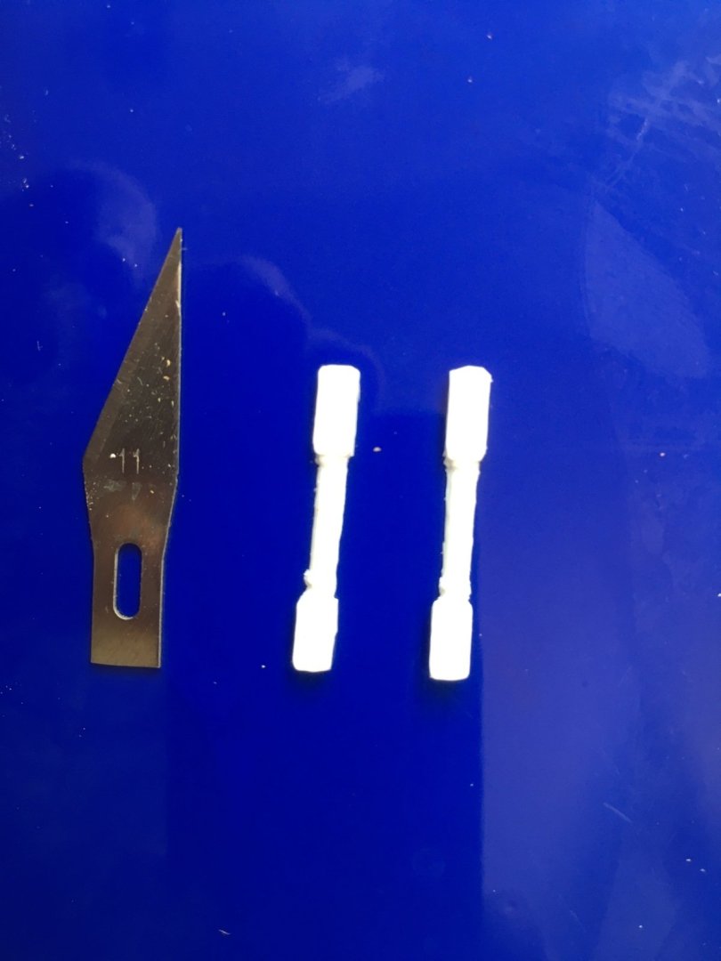
 I can't it's been a year since I updated this. I haven't worked much on the model since life's been hectic. Went on our first cruise ever one year ago. Lot of fun but the last night I started feeling rough. Got home the next day and tested positive for Covid! It took a while to get over it. Got through the summer chores and then the hurricanes hit. Lots to clean up. I've worked a little off and on but now I'm finally trying to get motivated to get back to the workbench. What I want to show today is that I am working on columns. I've tried several ways to make them using wood but I decided to try 3D printing for the first time. I put together a design and split it in half since I thought it might print better without having to have any supports. Then I could just glue the two halves together or use just a half of one if it needed to be on an edge or against a wall. My son works at the university library that has a printer I was able to use for free so I printed just one to test. I need to now try the printer at the public library to see if it is better quality. I made them long so I can cut them to length as needed. I need to do some cleanup, prime and paint. Lets see if I can attach the stl file if anyone wants it. Victory Columns.stl
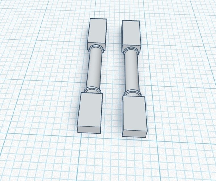

-
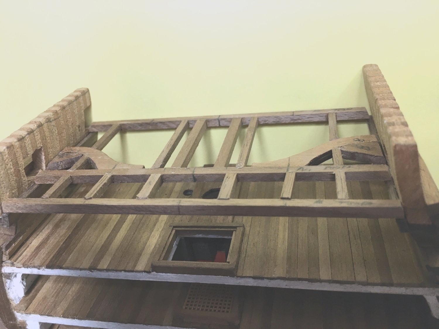
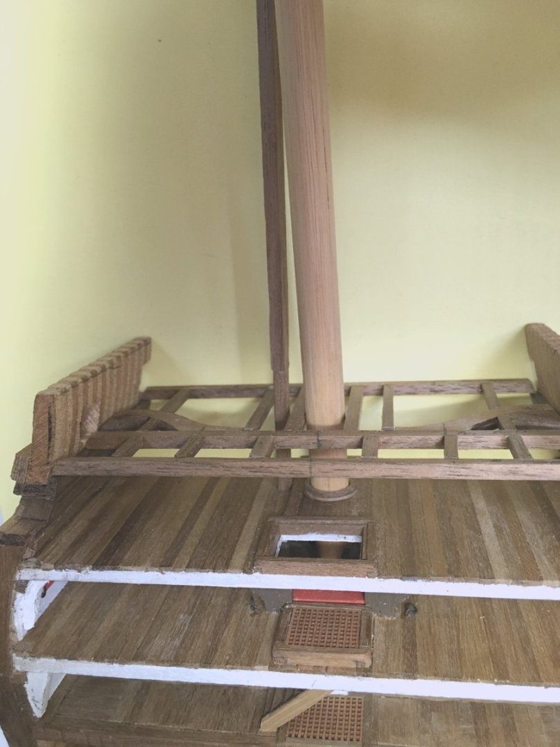
Just a quick update that I haven't given up on this. I’ve been away from this for a while. After many tests they finally found and removed the tumor that’s been playing havoc with me for the last year so now I hope to make up for lost time. I just need to remember where I was in the build. Beams for the upper deck test fitted. Like the other decks, I made this so I can slide it in and out as needed. Test fitting the main mast and what will become an elm tree pump to check for alignment and clearance between beams. Adding more structural members and planking. I cut a notch for the pump. Sliding the deck in for another test fit with the pump. I have to get the hanging knees shaped and located. Then I can slide this deck back out and finish out the middle deck with details and paint. Thanks. David


-
Good luck with your tests. I've put my build aside also while I've been getting medical tests. Hard to get motivated.
- 25 replies
-
- 2
-

-

-
- Victory
- Cross-Section
- (and 1 more)
-
Hi, from Balearic Islands, Spain.
Dlowder replied to Miguel Juan Calvo Fürst's topic in New member Introductions
Welcome aboard. David -
Welcome to the forum. David
-
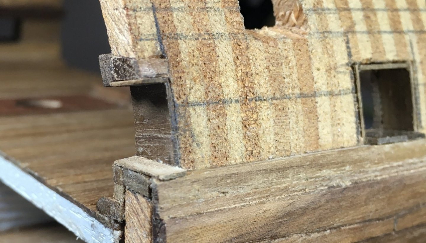
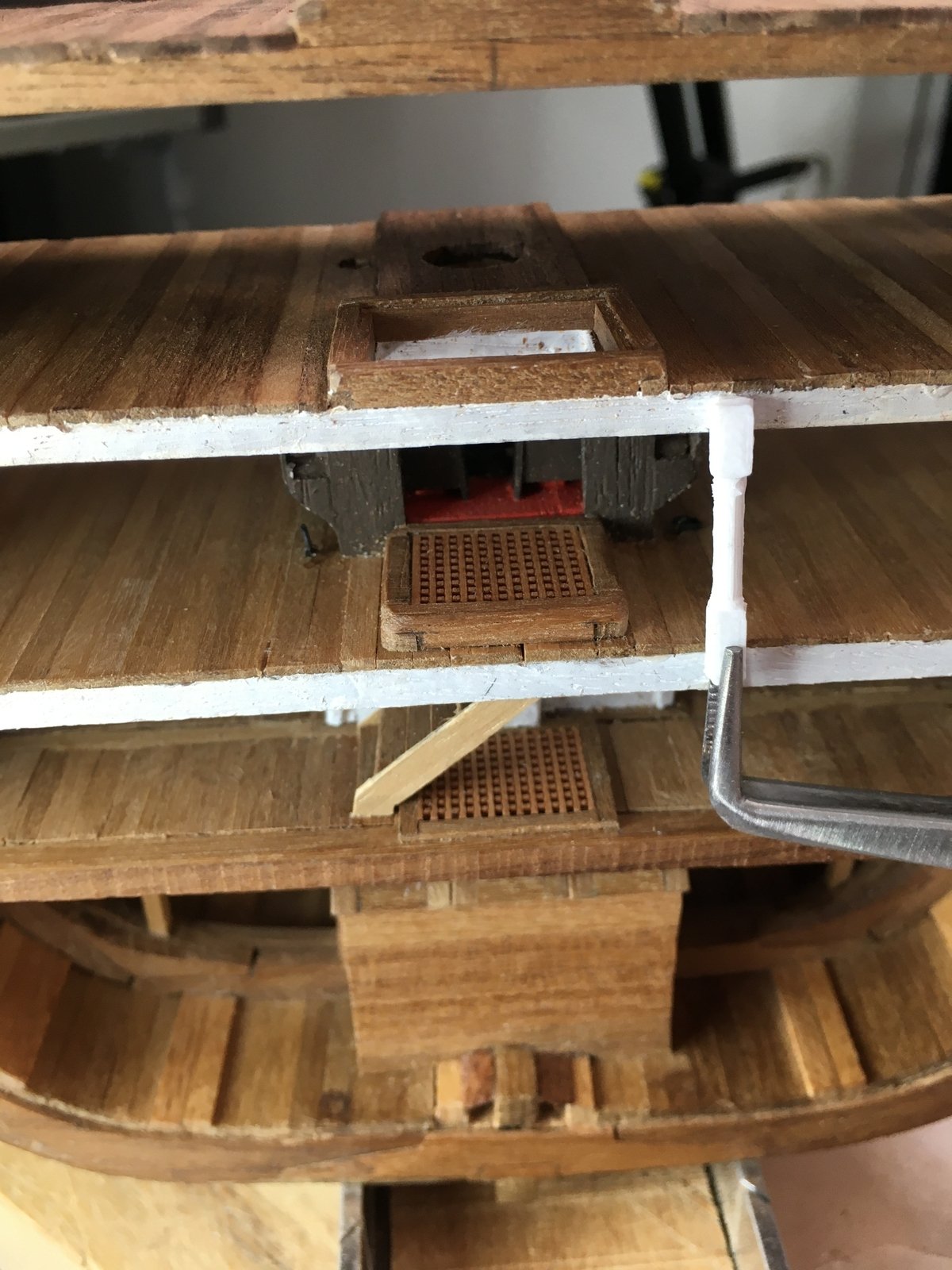
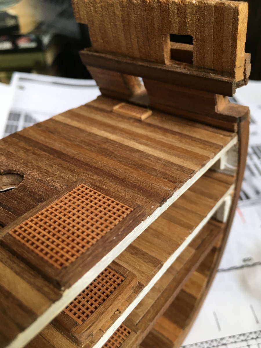
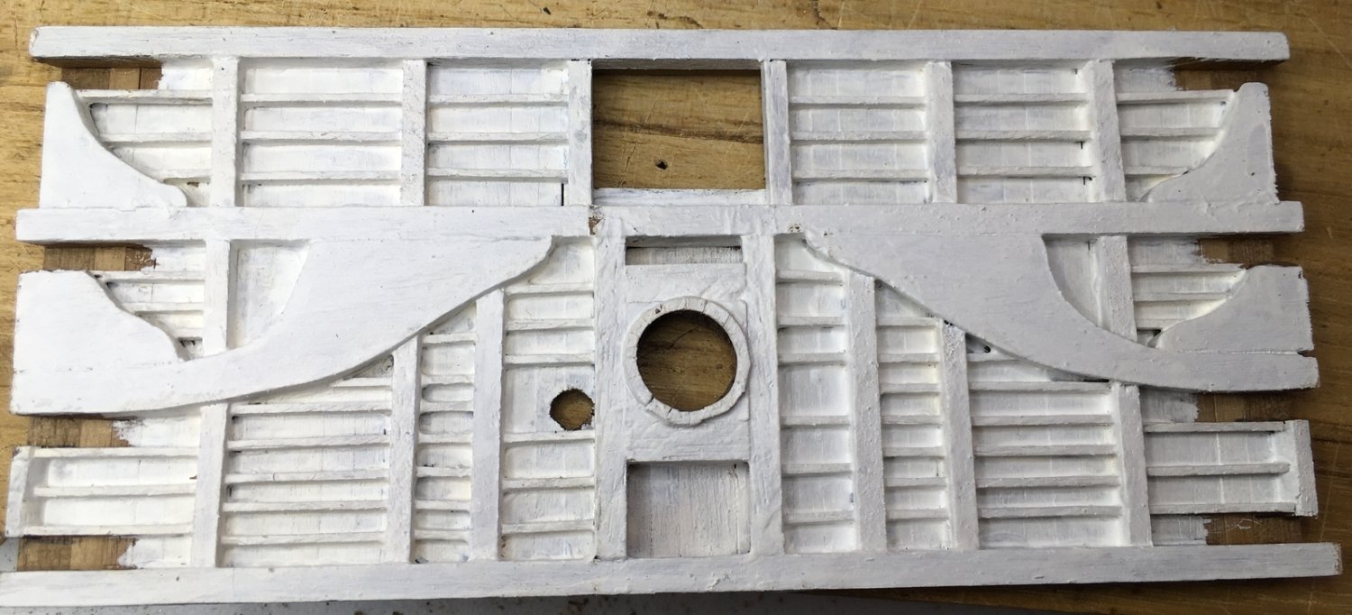
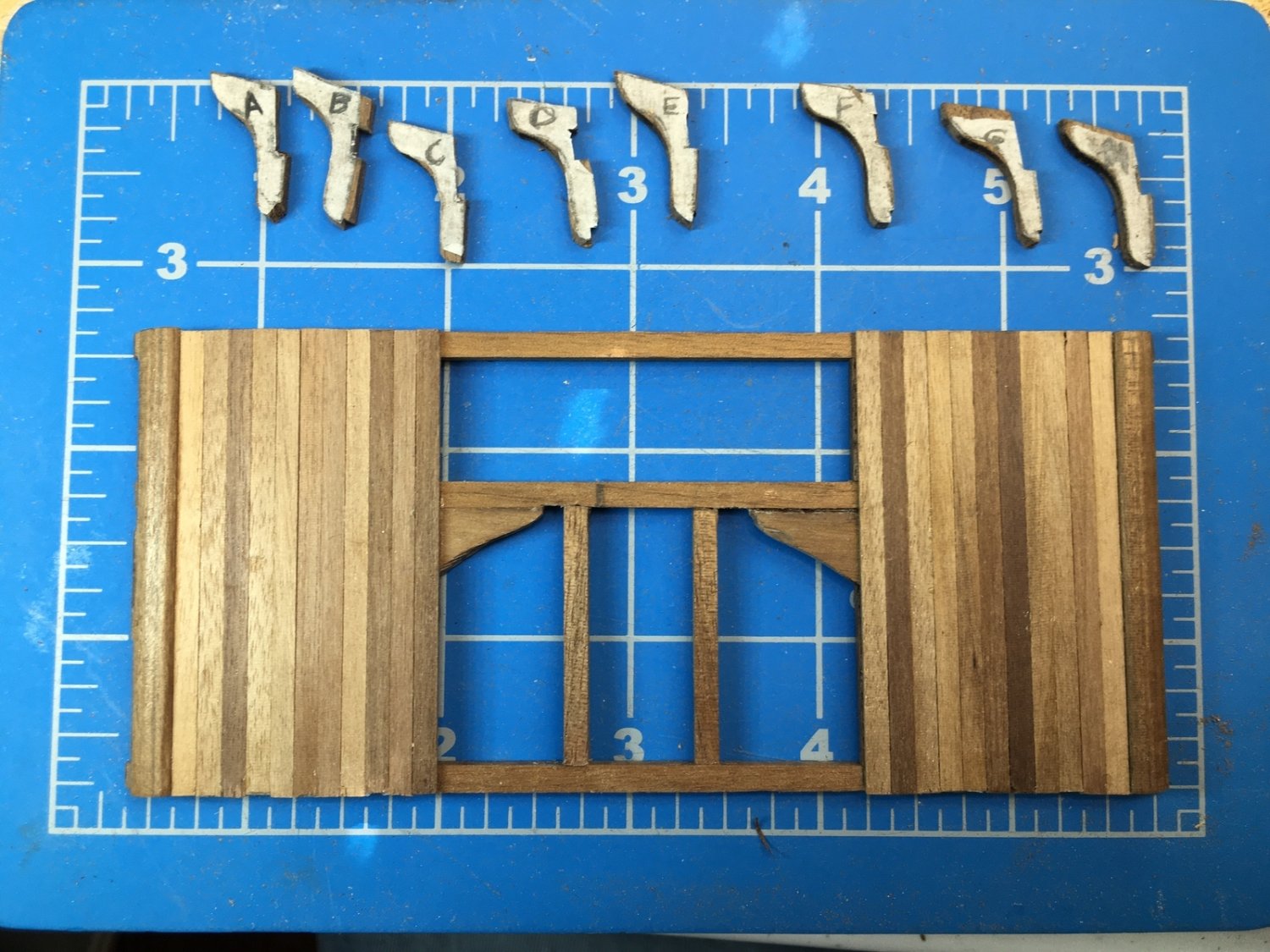
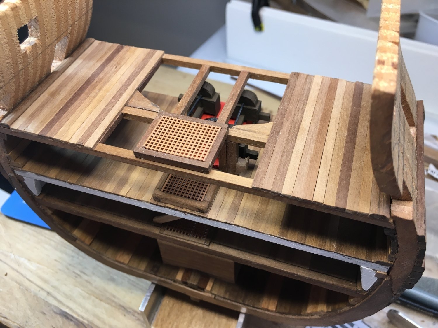
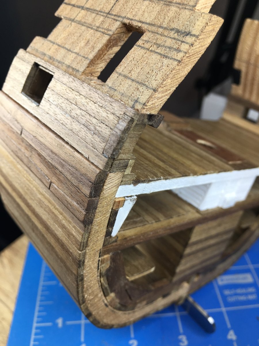
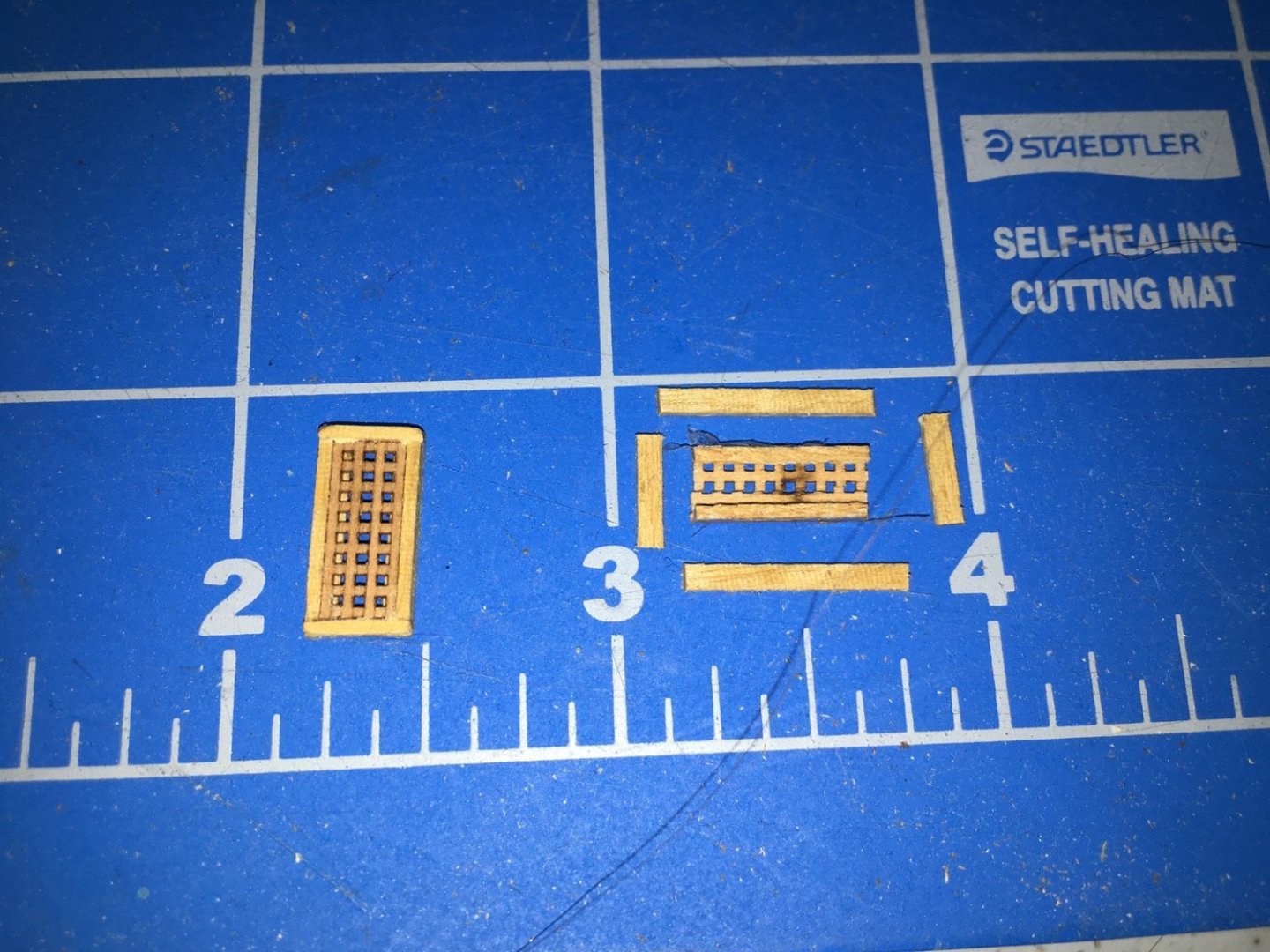
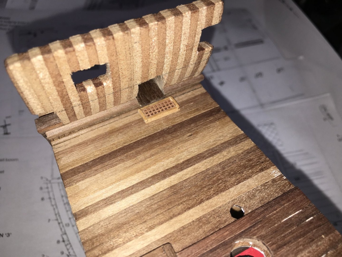
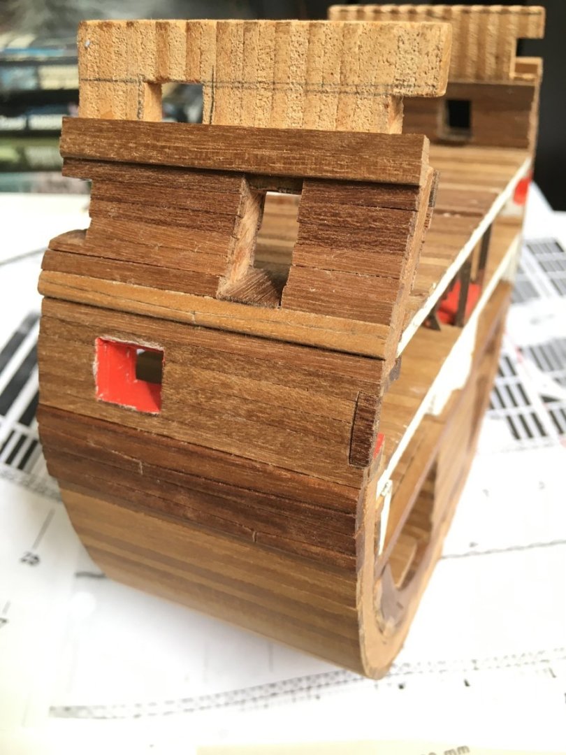
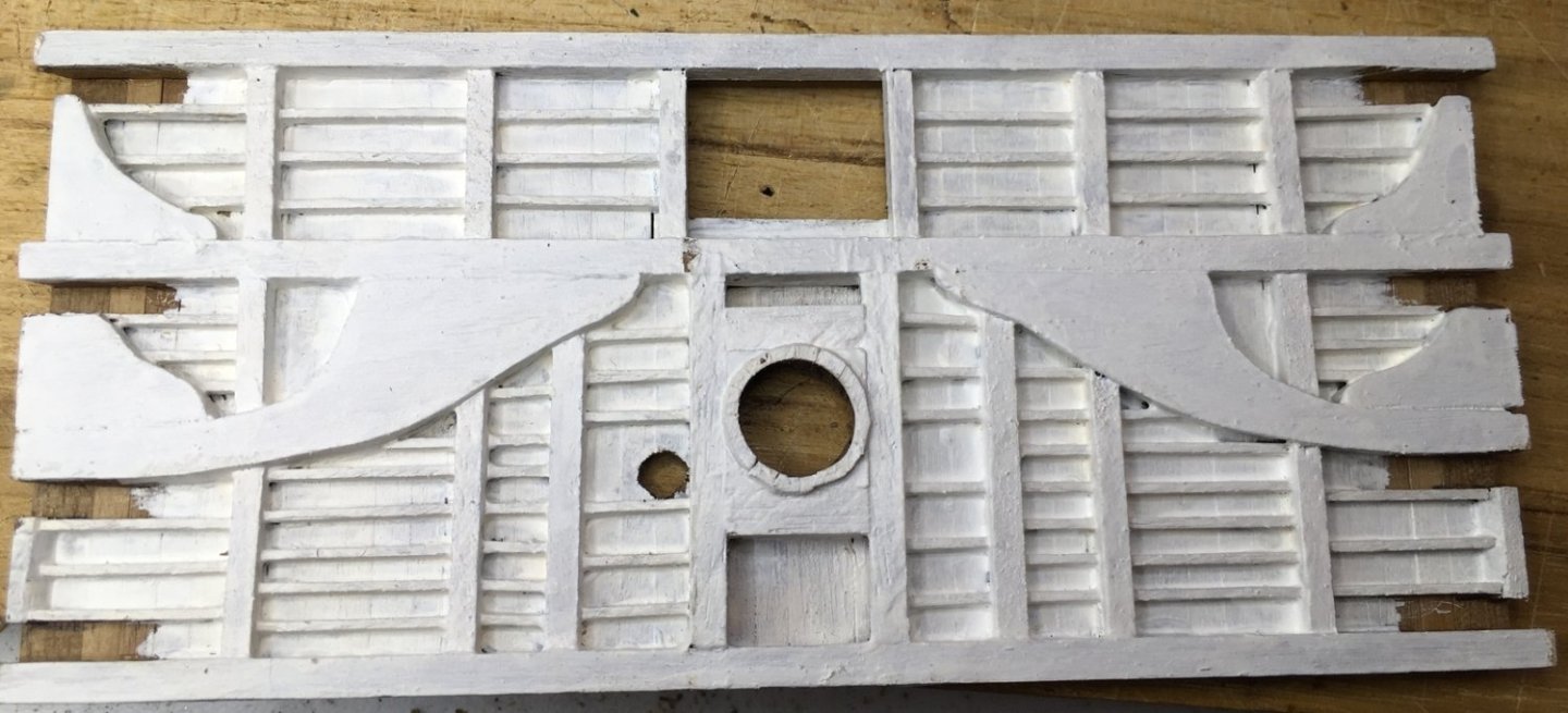
I’m back at it again. Been under the weather for a while so moving slowly on this. Plans from several sources show small grates at the entry ports so I built these using the same grate material as I used before. I’ll wait to glue them in place after I paint the deck sides. The octagonal hole in this deck is for an elm tree pump to will continue up to the upper deck. I planked up the exterior and interior with rough openings for the entry ports and the gun ports. I’ll clean them up when I add the linings. Next I'm working on the structure of the upper deck since there are middle deck fixtures that have to align with those beams. David

-
Entry Port Grates
Dlowder replied to Dlowder's topic in Building, Framing, Planking and plating a ships hull and deck
Thanks Greg. That's my original question… does anyone know how the water was drained? Would it be visible on my model or would it be hidden behind the grate? I'm going to assume that any drain point would be out of sight. I'm not trying to model an exact replica of Victory at any point in her career, I'm just trying to learn more about maritime technology of the period and replicate it in 3D. A generic ship of the line if you will. Sort of like the AISC Steel Sculpture for those engineers out there. https://www.aisc.org/education/university-programs/steel-sculptures/#9795 -
Entry Port Grates
Dlowder replied to Dlowder's topic in Building, Framing, Planking and plating a ships hull and deck
Thanks Dafi, I missed seeing the link in your post to the earlier thread. Just now read it. David -
Entry Port Grates
Dlowder replied to Dlowder's topic in Building, Framing, Planking and plating a ships hull and deck
Thanks for all of the replies. I'm no expert but I still think that, even if it wasn't designed for that purpose, it served to help drain any water coming in the entry port if it was open in foul weather. Several aspects of the entry points suggest to me that water infiltration was a concern. Goodwin's “The Construction and Fitting of the English Man of War 1650-1850” has an illustration on page 193 showing an example from 1670 with the entry port having a grated platform on the outside. I see no other reason for that one to be grated than to allow drainage for better footing. Also entry ports have canopies that must be there to prevent rain coming in but in a good blow rain would still get in and need to go somewhere. I think that anyone coming in wet from the rain will be shedding water once they are on that “welcome mat” and the water will need to go somewhere. Regardless of all that, it's bound to be too small a detail to represent in 1/98 scale on my model. Thanks again, David -
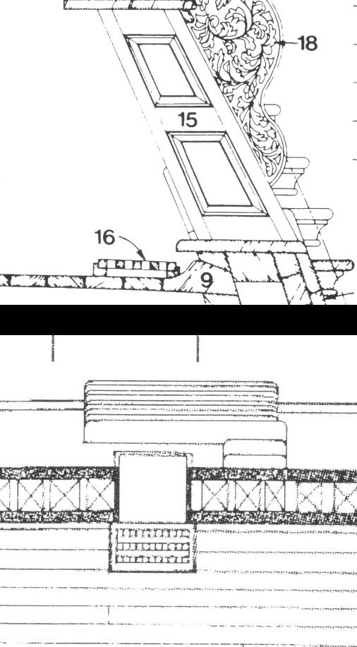
I hope this is a good place to ask this. I'm looking for more information on the grates on the deck at the entry ports for my HMS Victory cross section. I have one book with two drawings. One is the deck from above and the other is a cross section through the middle of the grate. I assume that these are here to drain any water coming it but I'm curious as to how the water drains out. Is there a scupper leading through the waterway or does it run out fore and/or aft in some way that's not shown in the drawings? If there is a scupper, it seems like it would be dumping water on the steps and make footing more challenging. On Victory today this appears to be covered with a ramp on the deck to prevent tripping. The view of the outside planking is also blocked in every photo that I've seen so I can't tell if there is a scupper. And maybe I'm being too picky in worrying about this. Thanks! David
-
Just catching up with this build. I'm very impressed. David
- 208 replies
-
- 1
-
-
- kitbashing
- Woodcarving
- (and 4 more)
-
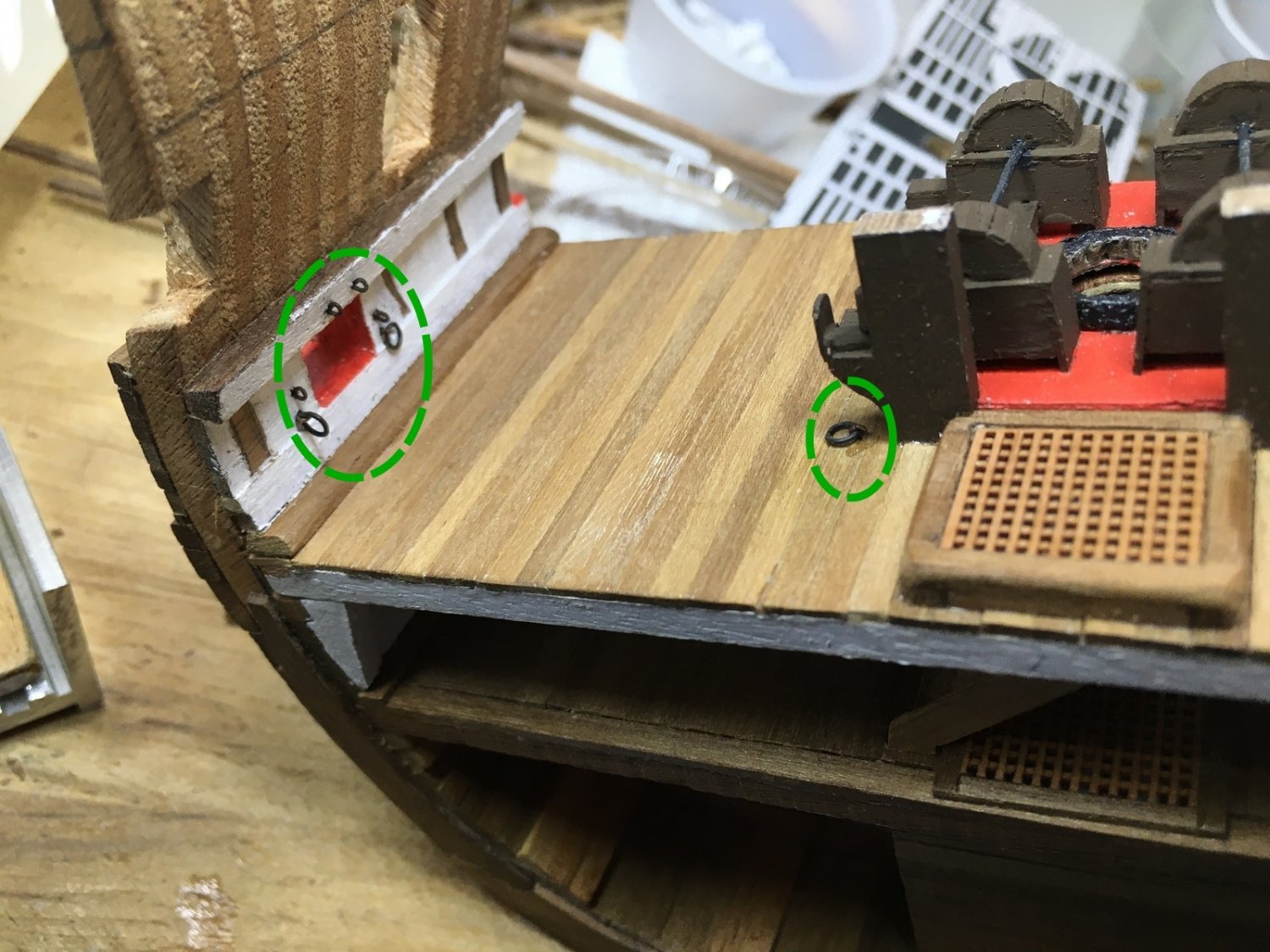
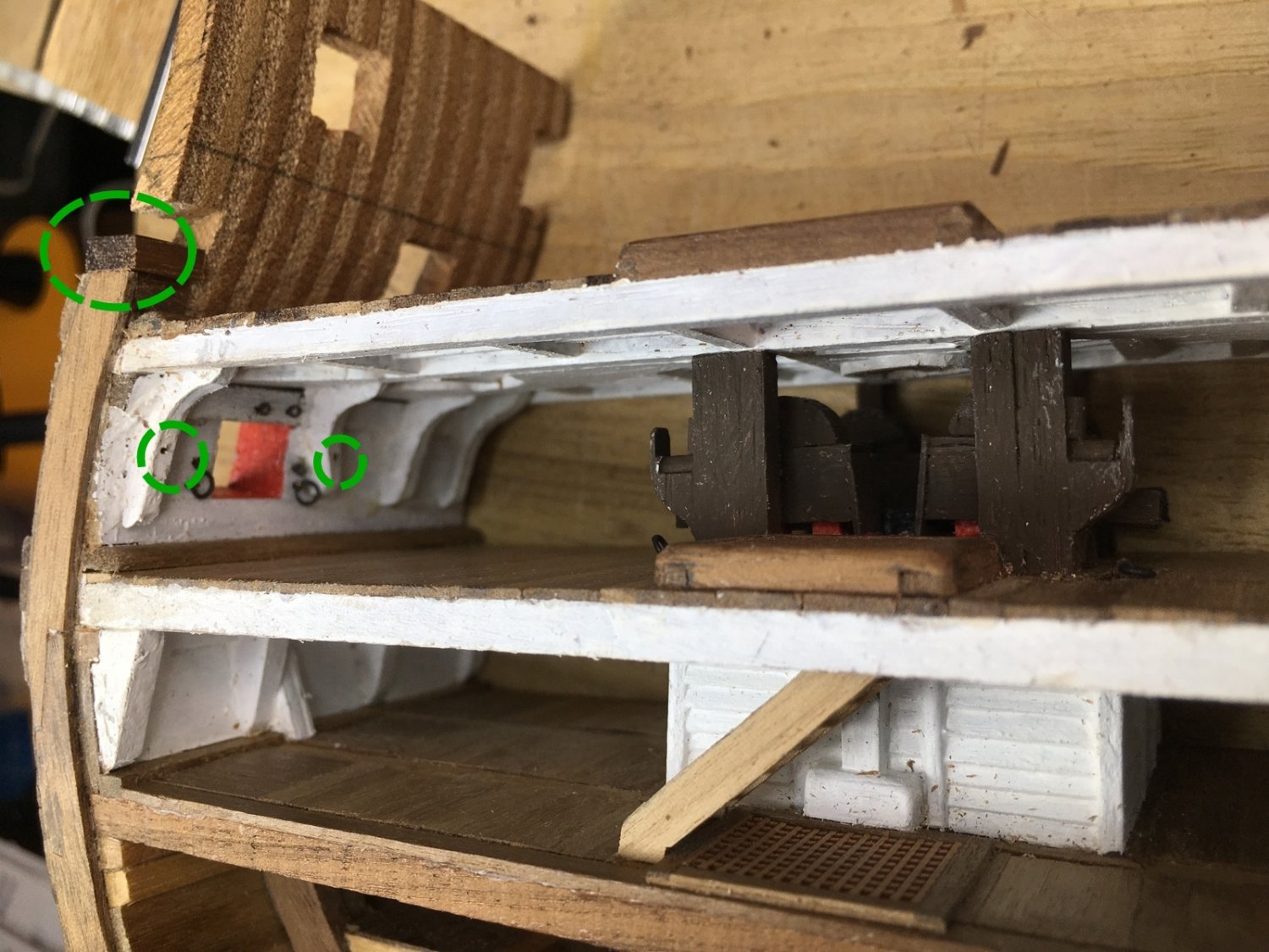
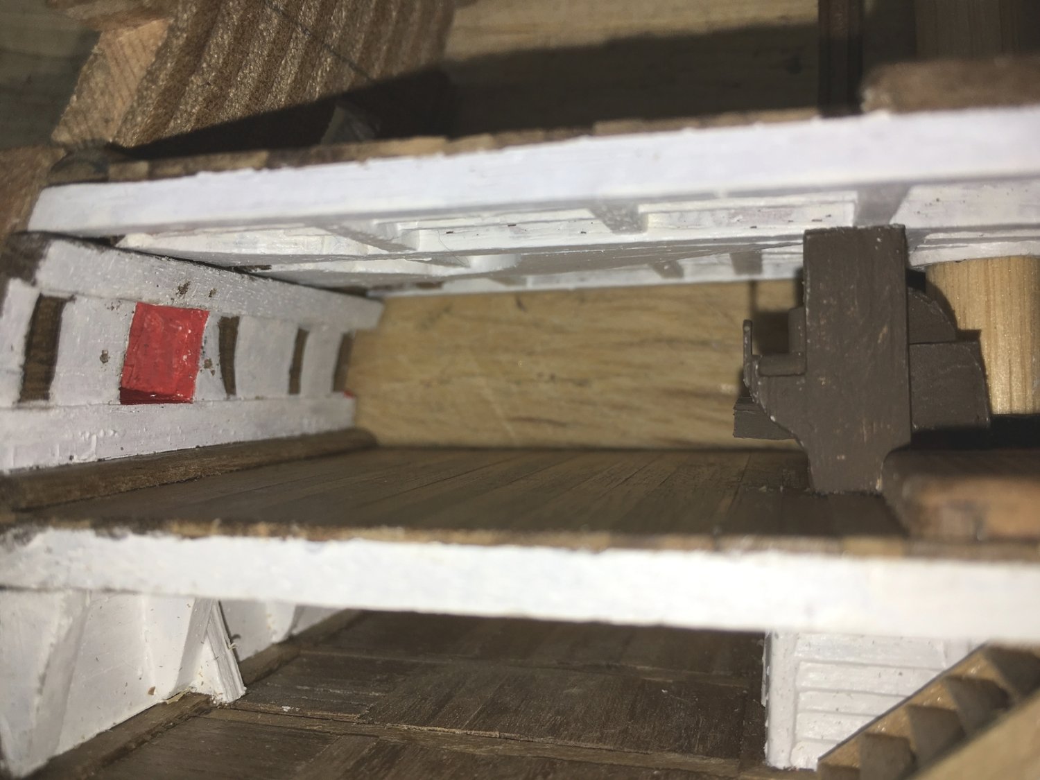
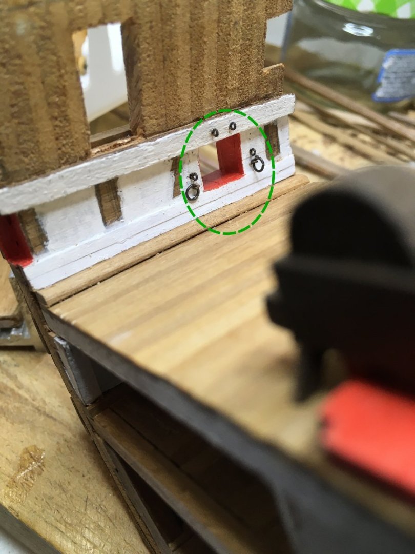
I haven’t felt up to working on this the last few months but thought I should at least update the log. I added eyebolts and rings to the ports and to the deck. I predrilled holes in the knees so I can add hardware there when I mount the guns. I installed the middle gun deck and then glued the knees in place. Before gluing I had very carefully shaped the knees to fit tightly in place but of course once I glued them in in, there were gaps where the fit was off. I mixed some sawdust with glue and packed it into the gaps before doing the touch up painting. I have an angled paint brush to make it easier to reach tight places. I added some more of the very thin walnut sheet to cover the rough kit material. I love this clamp. I also added the gun port sill. I need to increase the height of the ports. Speaking of clamps, I don’t remember where I got these screw in clamps. I’ve had them for years. They are too flexible for some areas but work well for places like this.


-
Welcome to the forum. I'm down in Statesboro.
-
Welcome to the forum. Nice work.
-
Welcome to the forum. I'm just up the road from you in Statesboro. David
-
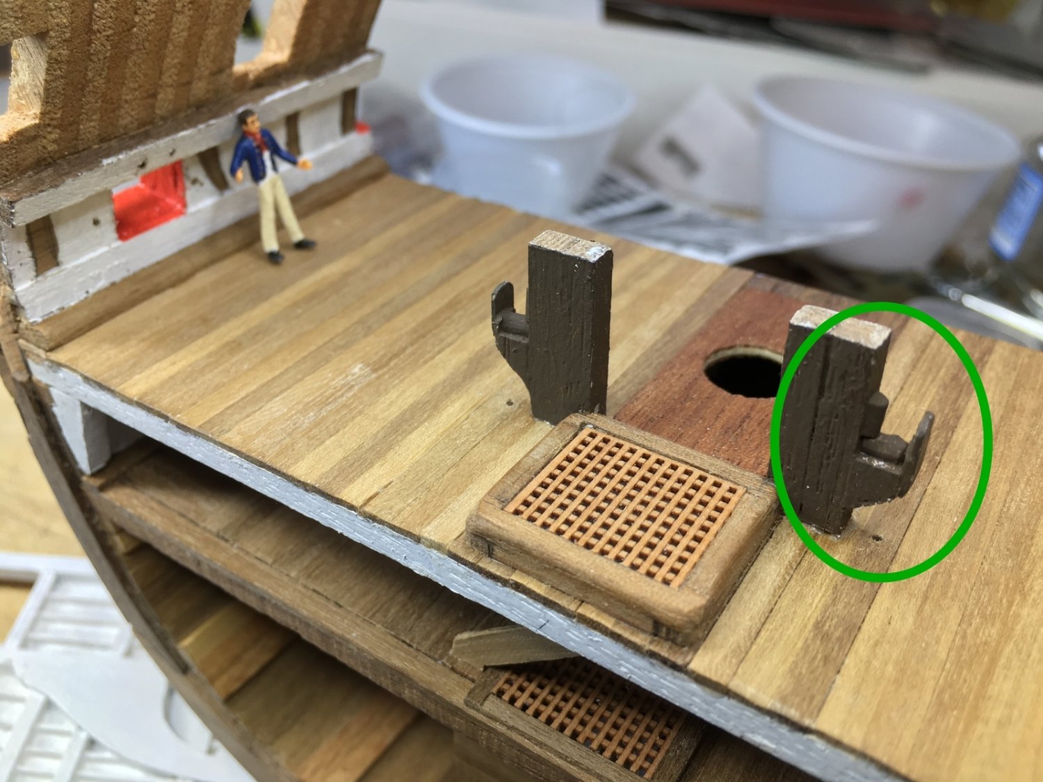
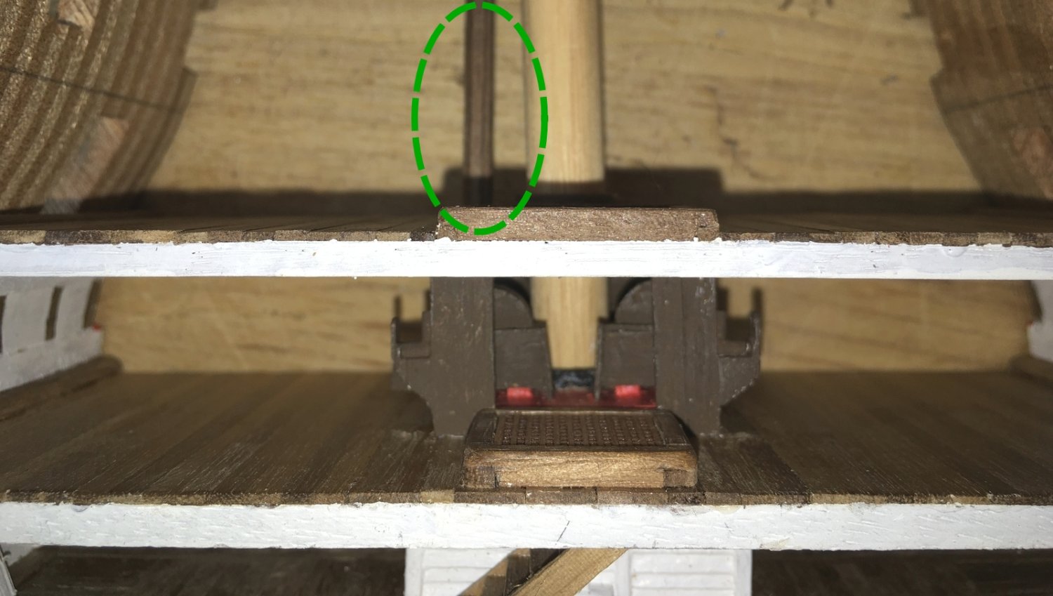
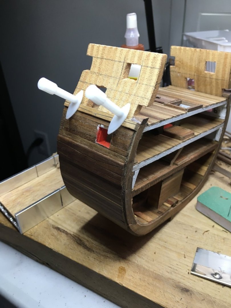
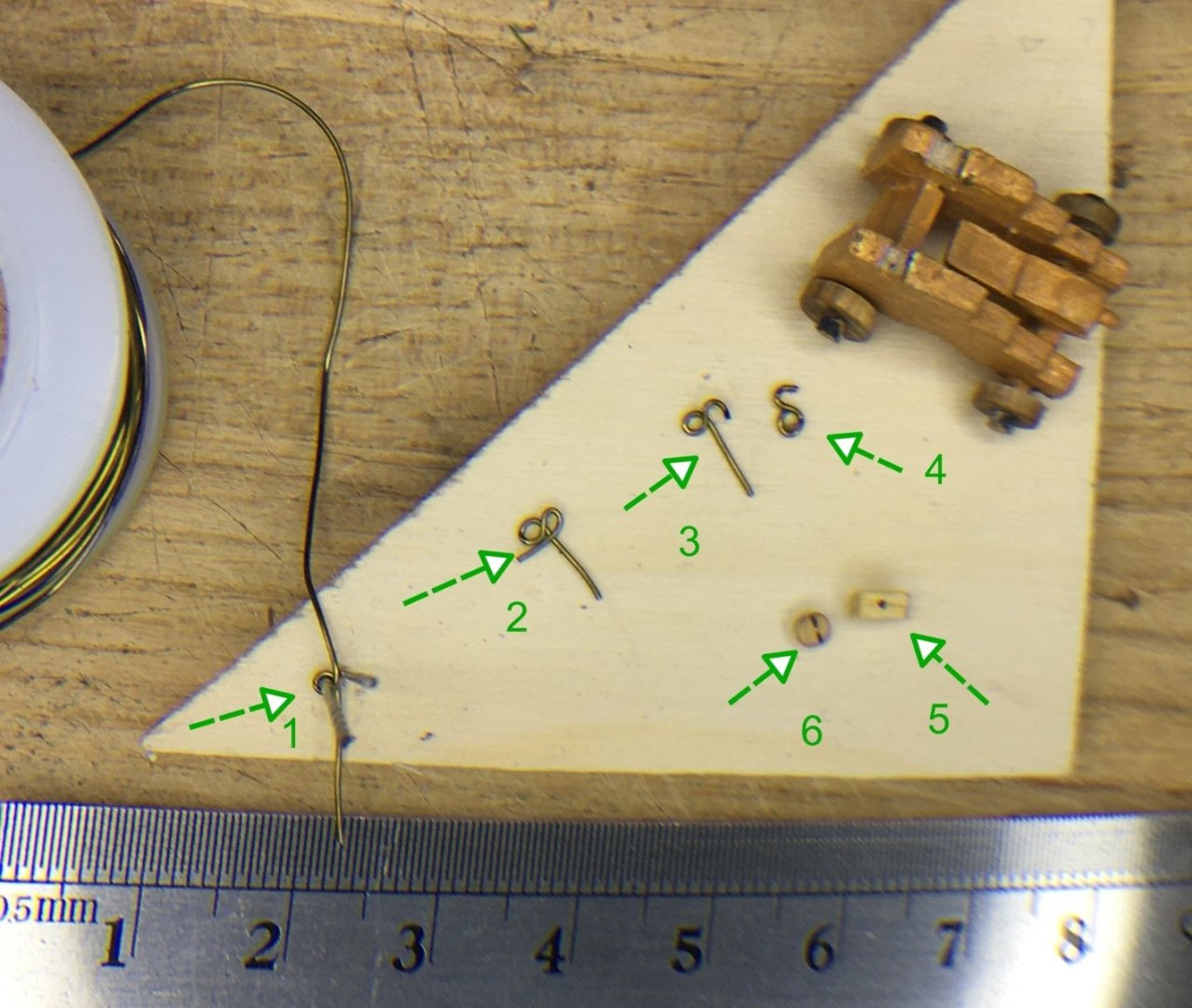
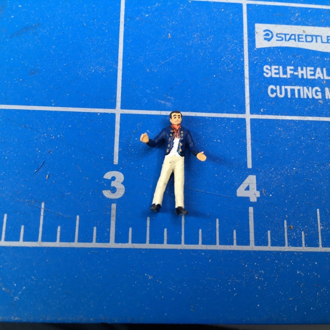
Hi. David here. It's been slow lately as I face new challenges with this. I'm thinking that I should add kit-bash to the title of this. I've built the middle deck structure and painted it. The paint is thin in places but too thick in the corners. It's the underside so I don't think it will show. Parts were left unpainted so I can glue the knees in place and have a good surface. I'll touch up that paint once the deck is in place. One thing that's not in the Victory plans I have is the mast partners and people touring Victory now never seem to look up when they take photos so I had to rely on general texts about period ship building. The hole to the left of the mast is for an elm tree pump on the upper deck. That's another thing that I would like to find a good photo of since I'm interested in how it was waterproofed underneath. Speaking of the elm tree pump, I didn't do a good job of trying to make the long one octagonal by sanding a square strip. At this scale and painted dark like the ones currently on Victory, it seems acceptable but I may redo it. For now I just need it for alignment. I simulated rollers on the cable lifters but using round toothpicks cut in half lengthwise. I don't want to close up the deck until I install the hardware. I'm finishing the guns but having a few issues. I found some leftover brass photoetch that had border strips of the right width and bent them. I can't get a good tight right angle for the transition from flat to curve. I'm tempted to try doing them as a semicircle with two flat pieces fastened to it. It might be better looking to use tape. The eyebolts that come with the kit are too large for real eyebolts but about right for the size of the rings. They need to be shaped more round. Instead I had some small eyebolts and made rings from some copper wire. I have some Blaken-it that is very many years old so I tried to use it. Diluted it didn't work so I tried full strength. It darkened the brass some but not enough and rubs off. I'm trying paint next but I also just ordered some Artistic Wire that should be here in a week and I'll see how that does. Once I get the eyebolts and rings finished I can attach them to sides of the deck since they will be hard to get to once the middle deck is glued in place. Rigging the gun carriage. The blocks from the kit (5) are just basic and would take time to improve so I splurged on some blocks from Syren (6) and they look great! I made some hooks from copper wire. I put two small drill bits in a scrap piece of wood. I started with the wire between the bits (1), wrapped it around the left bit, back up the middle and around the right bit (2). I cut the right one off to make the hook (3) and cut the left one flush to make the loop (4). I think they look good but I will wait for the new black wire to see how that works. Since these are for the gun tackles they will be hanging loose so I don't think I need to worry about sealing the loop. I will rig the guns in place to get the ropes looking good and then remove them until I finish the kit. I don't want them to shake loose. I also painted my little sailor figure that I stole from a plastic kit. Big bushy eyebrows on that fellow. Thanks for tuning in. David


-
Welcome to the forum. I keep meaning to pay a visit to Savannah's Ships of the Sea museum. It's been years since the last time. David
-
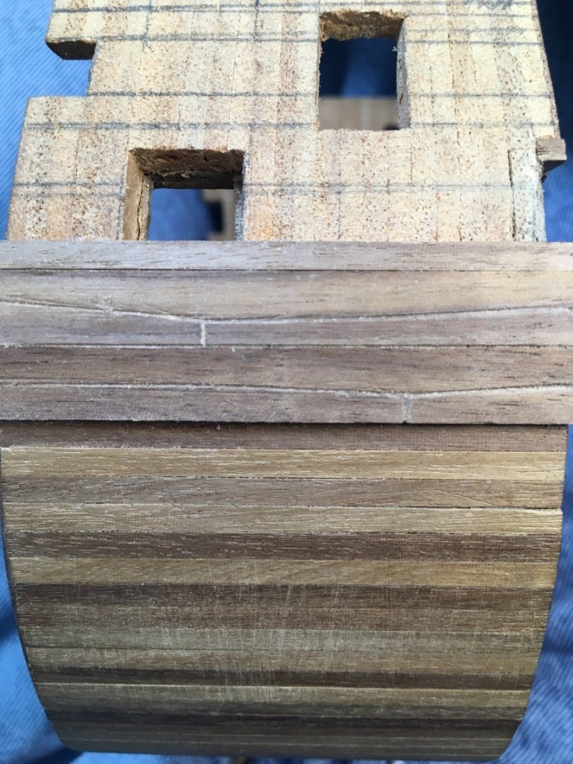
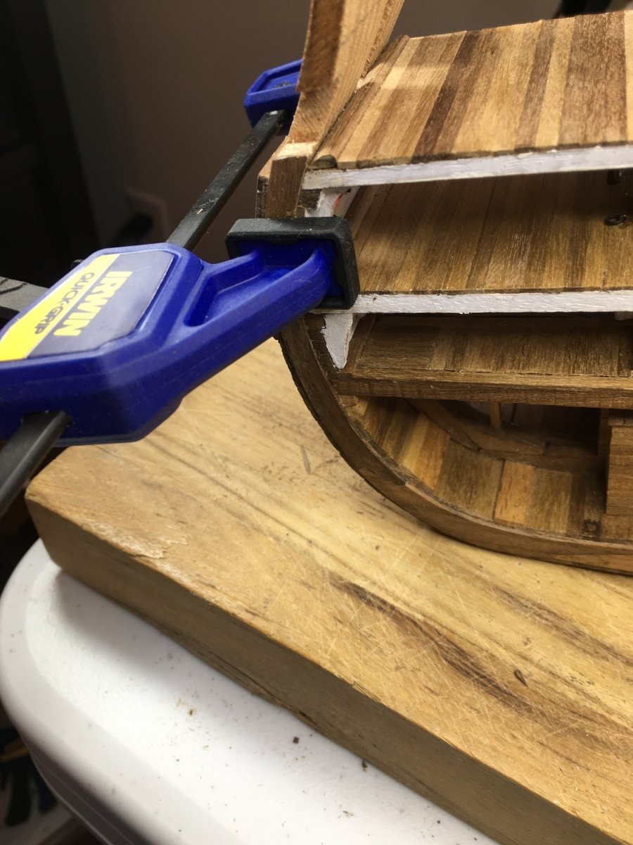
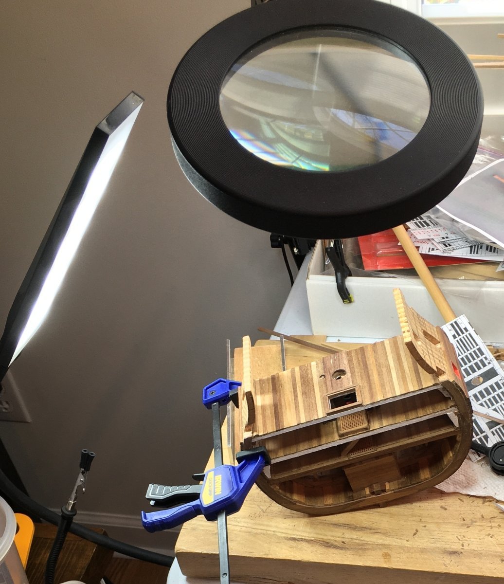
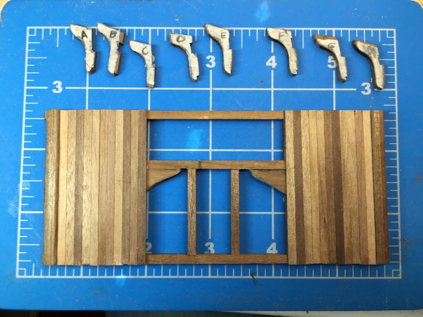
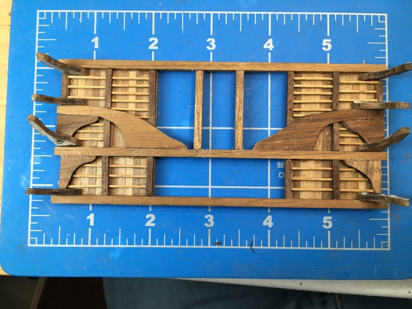
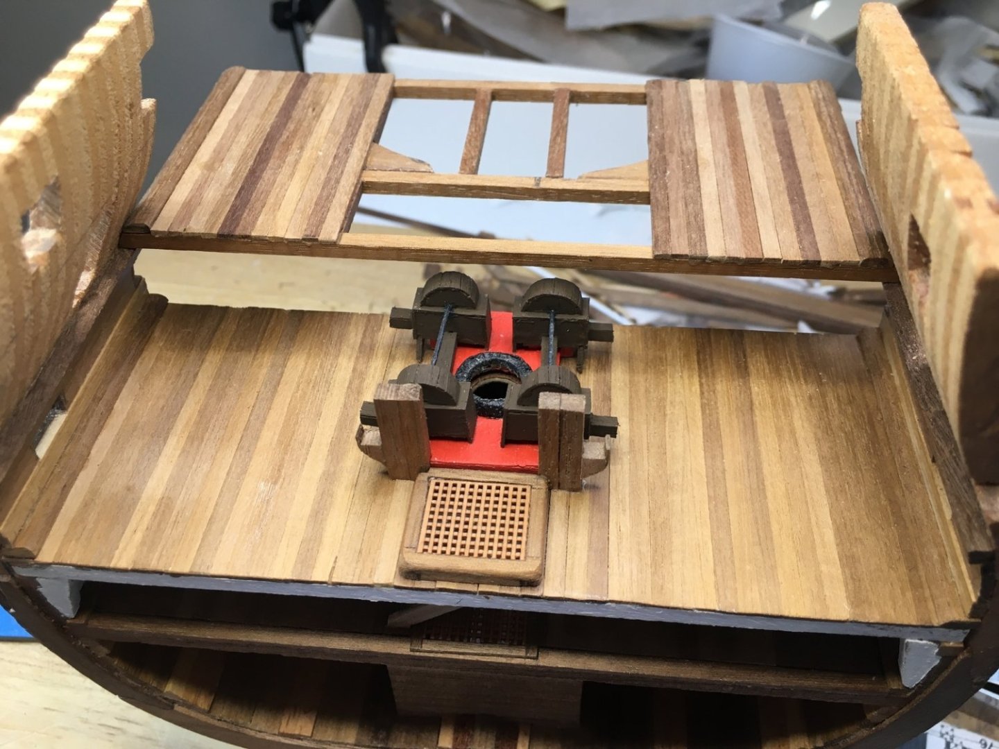
Since I last posted I’ve moved my workspace from the spare bedroom to the study. I still have what I think must be the messiest table out there! But I face a window now instead of a blank wall. It’s a challenge having to make up my process as I go along. I need to finish the lower gun deck but I think I need to build the middle gun deck first so I can locate things like hanging knees, eyebolts, support pillars etc. But if I install the middle deck then I won’t be able to get to the lower deck to paint and install fragile things like gun carriages. But if I paint now then I won’t have a bare surface to glue the knees. I've been uncertain how to proceed. My solution is to again build the deck so I can slide it in and out. I can slide it in so I can measure and cut the hanging knees. I can slide it back out, paint the sides of the lower deck leaving bare surfaces where I have marked the locations of the knees. I’ll install eyebolts for the guns and the port lids. Then I can slide the deck back in and use tweezers to glue the knees into the prepared locations and then touch up the paint. I hope it works out! Since I started this a long time ago and then ripped out what I had done to start over, I have run out of deck planks. I have ordered more so I’ve only planked the outer portions of the deck until the shipment arrives. Some of these are a lot darker than I like so I may replace them if the new strips look better. I shaped and installed the waterways. I’ve labeled the hanging knees so that I know where they fit. I’ve left the templates tacked onto them for now. This shows the underside with the beams, beam arms, lodging knees, carlings and ledgers installed under the planks that I have. For the picture I placed the hanging knees where they will eventually fit. One on each side will be placed at an angle to keep from blocking the gun ports. Now that I have the height of the middle deck, I placed the support pillars that go between the chain pumps and the hatch. The cable lifters are made from shaped 3mmx3mm with 0.6x3mm strip glued on the side. I’ll probably try to add rollers if I can get them small enough and I’m not sure if I will end up adding the messenger cables themselves. I made the hatch for the middle deck differently than the other ones. Instead of cutting a rabbet to receive the grating, I made the hatch from 2mmx3mm strips and lined it with 1mm strips recessed the correct depth. It's not glued down yet, just positioned for the photo. Thanks for viewing. David


-
Deck planking plans
Dlowder replied to KingDavid's topic in Building, Framing, Planking and plating a ships hull and deck
Hi Allan, You are correct that Goodwin covers this. He says some builders used two strakes of top and butt or anchor stock four feet from each side of the ship on the gun decks. He says it was probably started towards the end of the eighteenth century. David -
Deck planking plans
Dlowder replied to KingDavid's topic in Building, Framing, Planking and plating a ships hull and deck
Yes Allan. In the image above from Rees's they are labeled as a beam arm. I'm wondering if there is guidance on placing the deck planks in relation to those. -
Deck planking plans
Dlowder replied to KingDavid's topic in Building, Framing, Planking and plating a ships hull and deck
Oops. I forgot I had a copy of Rees's naval architecture and in the included plans I found this showing the butts of the deck planks. I would still like to find any other information though if anyone has anything.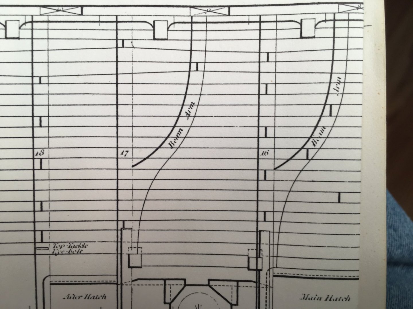
-
Deck planking plans
Dlowder replied to KingDavid's topic in Building, Framing, Planking and plating a ships hull and deck
Excuse me if this has been answered elsewhere but do the locations of half beams make a difference in the shift pattern? It seems like they would since they leave a big gap in the fastening surface available. If so, can anyone point me to an example to look at? I can't find any specific mention yet in any of my sources. McKay's layout of the middle deck of HMS Victory show butts evenly spaced from the entry port across to the main mast even though there should be a half beam there. Is it just that he, and others, are just simplifying it? Artistic license so to speak? I have found photos on the web of Victory's elm tree pump on the upper deck showing a butt right next to the pump even though there shouldn't be a full beam there. Many thanks. David -
Thanks!
-
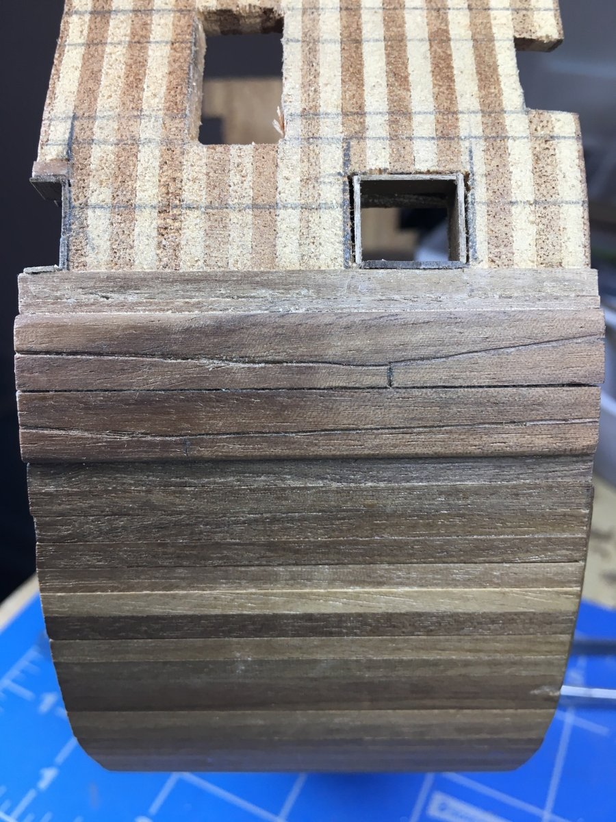
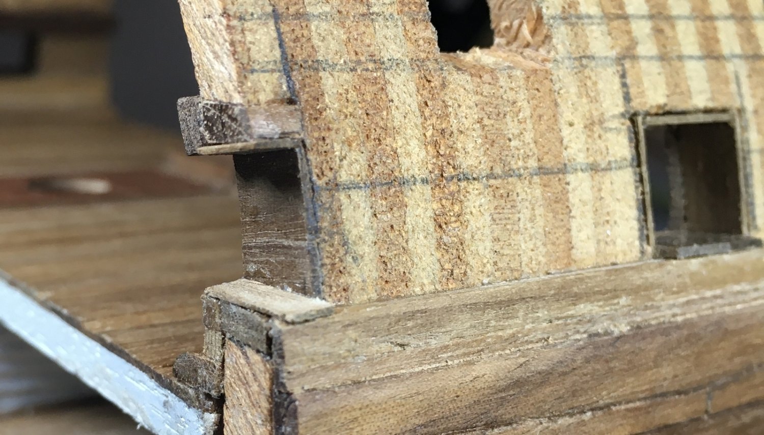
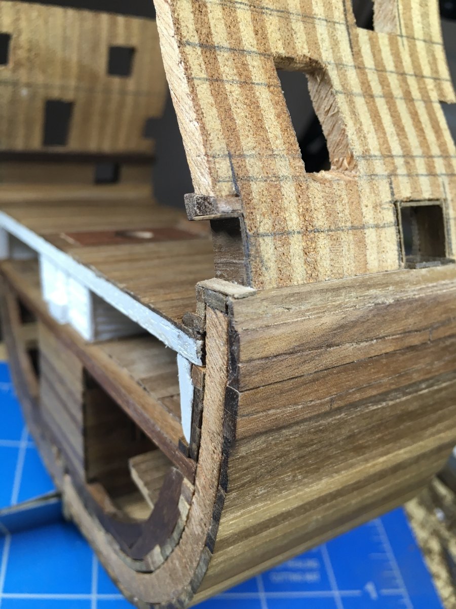
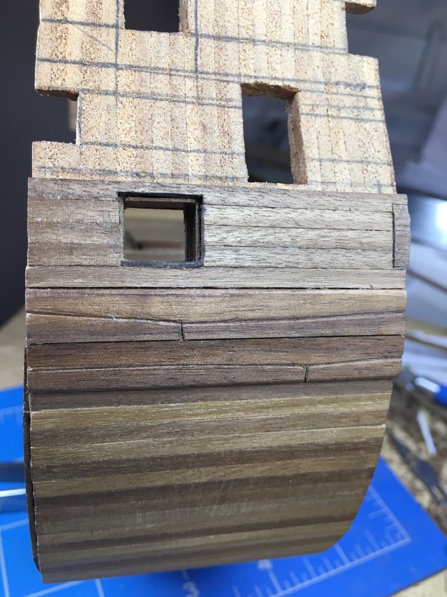
I haven’t done much in a few weeks. I relocated my work table from the spare bedroom to the study so that should help. I wanted to do the wales using top and butt planking but thought it would be too complicated to try to set up for just a few short pieces. I decided to use strips twice the width and scribe them to look correct. We’ll see when I get around to painting if the scribed lines are too wide. I lined the lower deck gun ports with thin strips leaving rabbets at the top and sides. For the ports that are partial because they are on the edge, I first enlarged the port and installed sills and lintels. This side of the model will be hidden but it was good practice since the ones one the upper deck will show. I cut short pieces of planking and glued them to a thin strip to create a cut off port lid and glued them closed. I was careful to make sure the planks on the lid aligned with the planks on the hull. I’m sure the partial lids would be too fragile to try to model open. Closer to the end of this build I’ll decide about having the full-size ports open or closed. David