garyshipwright
-
Posts
937 -
Joined
-
Last visited
Content Type
Profiles
Forums
Gallery
Events
Everything posted by garyshipwright
-
 Just to help out those in the hobby and new folks coming in to the hobby, here is a list of books that one may look in to getting for your library, or for those new to the hobby just starting to build up one. Weither it be PDF on the computer or hard back books that one just enjoy holding and reading. This isn't my list but one that Portia Takakjian figure would help others in the hobby. It is a list that I followed and since then have added even more books but does give one a base line to go by. Some are a little on the costly side and other's probably long out of print but do hope its of some help to you, it was for me. Gary
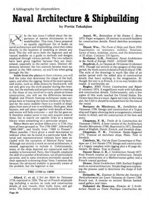


-
Hi Don. No question is stupid sir. As far as which one I use the most it would probably be Peter Goodwin's book, Construction of the English Man of War. That one seems to be the one I reach for when starting to look for information, but it doesn't have all the information and leads me to other books in the small library. I do seem to find my self looking a lot in to David Antscherl book, TFFM HMN Swan, at the moment because of his cannon detail in his book, along with a few other things, like the construction of the stern. For intermediate model builder, hum, guess it has a lot to do with what time frame your interested in. I remember when I started I picked up several to help me in the learning process such as Harold Underhill Plank on frame models, along with Peter Goodwin construction of the English Man of War, Arming and Fitting by Brain Lavery, Harold Hahn, Ships of the American Revolution and Their Models, The Colonial Schooner, and David Antscherl TFFM. It does seem that once this bug bites you, if any thing like me, you buy every thing that just might hold that bit of information that could make your cannon rigging better or making better rope. Of course here on MSW it holds a lot of that information that really makes buying some books unnecessary. It would be nice if one book held all the answer's to our question's but they don't, which is why I believe we are always looking for that next book, that and a good read if nothing else. I do remember when I got in to this hobby a list I went by that was writtern by Portia Takakjian, on what books to add to ones library. It might be a good thing to put here on MSW when members are wondering what would be good to add to your library. Also can't think of a better way to remember this dear lady for the things she did for the hobby. Gary
-
Hi Folks. As Wayne has said seems that am classic bibliophile, with no hope in sight. Figure I would post my small library and it may help others on what books may be worth adding to their own library. Hope it does help. Not as big as Wayne's but it fits my need's. The name of the book is first followed by the author. If you want to know a little bit about the book and if it fits your needs just let me know. Gary English Maritime Books Printed before 1801- Adams/Waters Art of Building of Ships 1719 -Allard The Rigging of Ships in the Days of the Sprit sail Topmast- Anderson,R.C. Seventeenth Century Rigging.- Anderson,R.C. The Sailing Ship- Anderson,R.C. Encylopedie Methodiqiue, 1783-1787, 3 vols plus plates.- Ancre Dictionary fo Sea Terms- Ansted Album of Colbert 1670- Anonymous The Fully Framed model . H.M.S. Swan Class Sloop, vol 1, 2, 4- Antscherl,D The Fully framed Model. HMS Swan Class Sloop vol 3 -Herbert, Greg Shipbuilding Repository-1788 -Anonymous Album DeCobert-1670- Anonymous The Wooden Fighting Ship in the -Royal Navy Archibald The Ashley Book of Knots Ashley,-Clifford W. Building Britain's Wooden Walls, 1697-1851 -Barnard,John E Ships and Seamanship -Baugean,J.J. The Art of Gunfounding- Beer,Carel De A.O.S Royal Yacht Caroline -Bellaburla/Osculoti Sailing Rigs, An Illustrated Guide -Bennett,Jenny Mariner Mirror 5 CD set -Bethell,John P Cross Sections of Man Of War -Biesty Steering to Glory,A Day in the Life of a ship of the line -Blake,Nicholas Naval Expositer -Blankley,Thomas Album Del marques De La Victoria -Borbon, Carlos de The Sea. Its History and Romance. 4 Vols -Bowen,F Scale Model Sailing ships -Bowen,John Model Shipwright, Vol 1-131- Bowen,John An Anthology,1972-1997, Model shipwright -Bowen,John 2010 Shipwright -Bowen John 2011 Shipwright -Bowen John 2012 Shipwright- Bowen John 2013 Shipwright -Bowen John Artillerie De La Marine 1758 -Boudriot History of the French Frigetes,1650-1850- Boudriot 74 to 120 gun ships in the French Navy, 1650/1850 -Boudriot The Frigates in the French Navy,1650-1850- Boudriot Naval Gunnery in France, 1650-1850 -Boudriot La Belle Poule, 12 pdr Frigate,1765 -Boudriot La Venus, 18 pdr Frigate, 1782- Boudriot The 74 gun ship, 4 vols- Boudriot Compagnie Des Indes-2 vols- Boudriot John Paul Jones and the Bonhomme Richard- Boudriot La Salamander 1752- Boudriot Le Fleuron 1729, 64 gun ship- Boudriot Le Navire Marchand Ancien Regime L Mercure 1730 2vols- Boudriot La Jacinthe, 1823, Schooner- Boudriot 50 to 64 gun ships in the French Navy. 1650-1850 -Boudriot Le Trois Ponts Dw Chevalies De Tourville 1680,2 vols- Boudriot L Aurore 1766, Pleasure Sloop of War, 1766- Boudriot L Aurore 1784, Slaver- Boudriot Le Cygne 1806, Brig 24 guns -Boudriot la Belle Expendition Vessel, 1684, 2 vols- Boudriot La Diligente, The King's Tartan,138-1761- Boudriot La Renomme, 8 pdr Frigate, 1744 -Boudriot Le Requin Xebec, 1750- Boudriot La Salamandre, Bomb Ketch,1752 -Boudriot Le Coureur, Lugger 1776 -Boudriot Bonhomme Richard, 1779- Boudriot Le Cerf, Cutter 1779 Le Batearc De Lanveoc, Brest's single mast righ boat, 1780 -Boudriot La Creole Corvette 1827 -Boudriot La Chaloupe Armee En Guerre, 42 ft Longboat armed for War,1834 -Boudriot Le Francous 1683- Boudriot/Lemineur Le Bateau De Lanveoc -Boudriot/Berti Le Gros Ventre -Boudriot/Delacroix Encyclopedie Methodique/Marine Vol 1,2,3 and plates -Boudriot reprint Uniforms of the Royal Naval, 17th 18th century-Boudriot/Petard Lost Ships Bound, -Mensun The Model Ship, Her role In History -Boyd,Norman Napier Anatomy of an Admiralty Model (CD) -Bruckshaw,Robert H.M.S Victory, Building ,Restoration and Repair, 2 vols -Bugler,A Sovereign of the Seas -Busmann,H How to Carve Wood, A book of projects and techniques -Butz,Richard Nelson in the Caribbean, The Hero Emerges,1784-1787 -Callo,Joseph F Van De Velde Drawings in the National maritime Museum, 2 vols -Cambridge Neophty shipmodeler's jackstay -Campbell,G Old ships Figureheads and Sterns -Carrton The History of English Sea Ordnance, Vol 1- Caruana The History of English Sea Ordnance, Vol 2 -Caruana Vase 1, The Archaeology of a Swedish Warship of 1628- Cederhind/Hocker Search for speed under Sail -Chapelle History of American sailing Ships- Chapelle The Baltimore Clipper, Its origin and Development -Chapelle The History of the American Sailing Navy -Chapelle Architecture Navalis Mercatoria -Chapman Sailing Ships, Their History and Development,part 1 -Clowes,G.S. Laird Sailing Ships, Their History and Development,part 2 -Clowes,G.S. Laird The Royal Naval, 7 vols -Clowes,W.M Historic Architecture of the Royal Navy -Coad,J Early Sea Painters,1660-1730 -Cockett,F.B. Peter Monamy-1681-1749- Cockett,F.B The Age of Sail, vol1 -Conway maritime Press The Age of Sail, vol2 -Conway maritime Press The Decorative Arts of the Mariner- Cook,Gervis Frere Drawing of Nicholas Pocock, 1740-1821- Cordingly Figureheads, Carving on ships from ancient times to the twentieth century Costa,- Giancarlo Ship Models -Crabtree Royal Yachts of Europ -Crabtree, R The American Built Clipper Ship -Crothers Pilots,, The World of Pilotage under Sail and Oar, Vol 1 and 2 -Cunlifle,T Anchors, An Illustrated History -Curryer,Betty Nelson Naval Architecture 1695 -Dassie Pepys's Navy, Ships, Men and Warfare, 1649-1689 -Davies, JD Ship models and How to build them- Daviess,C The built up ship Model- Daviess,C Ship Model Builders Assitant -Daviess,C Art of Knotting and Splicing -Day,C.L Nelson's Favourite;HMS Agamemnon,1781-1809- Deane,A.N. Sailing ships(Dutch Prints) 16th to 19th century- DeGroat/Vorstman L'Amarante Corvette 1747- Delacroix, Gerard List of French Ships,1661-1715- Demerliac Memoirs of the Royal Navy -Derrick Building the Wooden Fighting ship.- Dodds/Moore Splintering the Wooden Wall -Dudley,Wade G Dictionay of Ship Types -Dudsyuis Element D' Architecture Navale, 1758 -Duhamel Du, Monceau Manufacture of Anchors Reaumur 1723-1764 -Duhamel Ship Modeler's Shop Notes -Edson The New Drawing on the Right Side of the Brain -Edwards, Betty The Restoration Warship -Endsor, Richard Grinling Gibbons and the Art of Carving- Esterly, D Falconer's marine Dictionary 1815 -Falconer,W Progressive Scratch-Building in Ship Modeling (CD)-Feldman,Clayton H.M.S Victory -Fenwick, K L'Artesien, Vaisseau de 64 canons 1764-1785- Fichant,Jacques Introductory Outline on Practice of Shipbuilding -Fincham,J A history of Naval Architecture- Fincham,J A treatise on Masting Ships and Masting making -Fincham,J Outline of Ship Building,1852 -Fincham,J Laying Ships off on the Mould Loft Floor.- Fincham,J USS Constellation, From Frigate to Sloop of War -Footner, Geoffrey M. Ship Models,1951- Fox A Distant Storm, the Four day Battle, Battle of 1666- Fox,F Great Ships; The Battle fleet of King Charles 2 -Fox,Frank Sailing Ships of War,1400-1860 -Fox,Frank The Great Ordnance Survey of 1698- Fox Frank/Richard Endsor Sailing, Seamanship and Yacht Construction- Fox,Uffa Navy Board Ship Models, 1650-1750 -Franklin,John Les Genles De La Mer -French Museum L' Art De Modelisme -Frolich,B To Build a Ship, the voc replica ship- Garvery,R Royal Yachts -Gavin Naval War of 1812 -Gardines,R Navies and the American Revolution,1775-1783 -Gardines,R Nelson against Napoleon -Gardines, R Fleet Battle and Blockade; The French Revolutionary War, 1793-1797 -Gardines,R Warships of the Napoleonic Era -Gardines,R Frigates of the Napoleonic Wars -Gardines,R Heavy Frigate, 18 pounder Frigates,1778-1800 -Gardines,R The Sailing Frigate, A History in Ship Models -Gardiner, R Nelson's Ships, a Trafalgar Tribute -Gardner,D The Floating Prison -Garneray,Louis The Ships of Trafalgar, The British, French and Spanish Fleets, Oct 1805 -Goodwin,P The Naval Cutter Alert -Goodwin,P Pandora, Bomb Vessel -Goodwin,P Nelson's Victory -Goodwin,P The Construction and Fitting of the English Man of War -Goodwin,P Nelson's Ships, A History of the Vessels In Which He Served. 1771-1805 -Goodwin,P The 20 gun Ship Blanford. -Goodwin,P Ships of the American Revolution and their models -Hahn.H The colonial Schooner -Hahn,H Marine Carving Handbook -Hanna,Jay S Trafalgar and the Spanish Navy -Harbron,John D Catchers and Corvettes, The Steam Whalecatcher in Peace and War,1860-1960 -Harland,John H Capstans and Windlasses -Harland,John H Seamanship in the Age of Sail, 1600-1860 -Harland, John F.H.Chapman, The First Naval Architect and his Work -Harris,Daniel G Manual of Traditional Wood Carving -Hasluck,Paul N Log of the Union -Hayes,Edmund The Ships of Abel Tasman -Hoving,A/Emke,C Nicolaes Witsen and Shipbuilding in the Dutch Golden Age -Hoving,A.J. The Staten Jacht Utrecht 1746, Sea Watch Books -Hoving,Ab Marine Art Of Geoff Hunt -Hunt,G Tall ship in Art -Hunt/Myers A Treatise on Naval Architecture -Hutchinson, W The Model shipbuilders manual of Fittings and Guns -Isard History of Art -Janson,H.W. Bound for Blue Water- Jineshsan Charles Brooking,1723-1759 -Joel,D The Great Age of Sail -Jobe,J The Period Ship Handbook, 2 -Julier, Keith Modelling Late Victorian Battleships -King,Brian The Kriegstein Collection, 17th and 18th century ship Models- Kriegstein Brothers The Lore of the Ship- Kelalbery,B Gunfounding and Gunfounders -Kennard,A.N. Portsmouth Dockyard Papers,1774-1783, The American War -Knight,R American Heavy Frigates, 1794-1826 -Lardas,Mark Trincomalee -Lambert,A Life in Nelson's Navy -Lavery, B Marine architecture, Directions for Carrying on a ship,1739, Edmund Bushnell -Lavery,Brian Jack Aubrey Commands -Lavery,Brian The Royal Navy's First Invincible, 1744-1758 -Lavery,Brian Nelson's Fleet at Trafalgar- Lavery,Brian Nelson Navy, 1739-1815 -Lavery,B The Arming And Fitting of the English Ships of War, 1600-1860 -Lavery,B Ship of the Line, 2 vols -Lavery,B 74 gun ship Bellona -Lavery,B Building the wooden walls -Lavery,B Dean's Doctrine of Naval Architecture, 1670 -Lavery,B Ship models, Their purpose and development. From 1650 to present -Lavery,B Line of Battle- Sailing Warship, 1650-1840 -Lavery,B Nelson and the Nile, The Naval War against Bonaparte -Lavery,B Ship Board Life and Organisation 1731-1815 -Lavery,B Ship Modeling From Scratch -Leaf, Edwin B. Masting and Rigging of English Ships of War, 1625-1860 -Lee,J Endeavour,a pictorial record of the building of the replica of H.M. Bark Endeavour- Lefroy,Mike Young Sea Officer Sheet Anchor -Lever,D Anatomy of Nelson's ship- Longridge,C Modeling the Cutty Sark -Longridge,C The Blackwall Frigates -Lubbock, Basil Modelos De Arsenal, Del Museo Naval -Lunwerg Album Del Marques De La Victoria -Lunwerg Sea Battles in Close up. The age of Nelson- Lyon,D Sailing Navy List- Lyon,D The Sail and Steam Naval List- Lyon/Winfield Ships in Minature -Macaffery,L Building plank on Frame Ship Models- MaCarthy,R Sails Through the Centuries- Macfie,G The schooner, Its Design and Development from 1600 to the Present -MacGregor,David R Merchant Sailing ships. 1775-1815- MacGregor,David R. The boats of Men of War- May,W.E. Frigate Constitution and other Historic ships -Maqorew Artillery of the Navy (Ed. canvas) 1758 -Maritz The Global Schooner, Origins, Development,Design and Construction,1695-1845- Marquardt, Karl Heinz 18th century Rigs and Rigging- Marquardt,K AOS, HMS Beagle -Marquardt,K A Most Fortunate Ship Martin,- Tyrone G H.M.S. Sussex, 1693 McArdle, Gilbert Ships, from the archives of Harland and wolff, the builders of the titanic -McCluskie,T H.M.S. Victory, Her Construction, Career and Restoration- McGowan The Ship, the Century before Steam -McGowan,A The Ship, Tiller and whipstaff -McGowan,A Granado, 24 gun Frigate -McKay/Coleman The Hudson's Bay Company's 1835 steamship, Beaver -McKay, John The 100 gun ship Victory- McKay,J The Practical ship-Builder, 1839, Facsimile reprint, 1940 -McKay,L Granado, 24gun Frigate -McKay/Coleman Shipbuilding in Miniature- McNarry,D Naval Guns, 500 years of Ships and Coastal Artilley- Mehl,H William Frederick's1874, Scale Journey- Mendez,Antonio American Ships of the Colonial and Rev Periods- Millar Building Early american Warships- Millar The Elements of Naval Architecture, Or A Practical Treatise on Shipbuilding 1764- Monceau, Duhamel/Murray,Mungo Naval Architectuure Elements 1758 -Monceau, Duhamel Historic ship Models -Mondfelt Spars and Rigging, from Nautical Routine,1849- Murphy,J.M/Jeffers,W.N. A Treatise on Shipbuilding and navigation in Three Parts -Murray, M Sailing Ship Models -Nance Legacy of a Ship Model, Examining HMS Princess Royal 1773 -Napier,Rob Queen Anne's Navy -Navy Records Society The Sergison Papers -Navy Records society Schooner Sultana, Building A Chesapeake Legacy -Niemeyer,L/McMullen,D Ships' Plans -NMM The Portrait of Peter Pett and the Sovereign of the Seas -NMM Plymouth's ships of War, Maritime Monographs and Reports, no 4-1972 -NMM 18th Century Shipbuilding, Remarks on the Navies of the English and Dutch, 1737- Ollivier,Blaise Traite De Construction, 1736 -Ollivier,B Naval Veneziane, Venetian ships- Penzo,Gilberto Rigging Period Ship Models- Petersson, Lennarth Modeling the Brig of war Irene -Petryes,C.W. Warships of the King. Ann Wyatt(1658-1757)Her life and Her Ships -Philbin,Tobias/Endsor, Richard Navy Board contracts,1660-1832- Pool,Bernard Danish Figure heads -Poulsen,H The Warship Figureheads of Portsmouth- Pulvertaft, David Figureheads of the Royal Navy -Pulvertaft, David Building A Miniature Navy Board Model -Reed, Philip Modelling Sailing Men Of War -Reed, Philip Period Ship Modelmaking, An Illustrated Masterclass.- Reed, Philip Rees's Naval Architicture, 1819-1820- Rees's Ship Models from Kits- Riches, Colin A Marine Vocabulary -Roberts, David The painting of the Willem Van De Veldes -Robinson Allgemeines Worterbuch Der Marine, 4 vols -Roding,J.H. The Wooden World, An anatomy of the Georgian Navy -Rodger, M.A.M. HMS Warrior 74 gun Ship, 4 vols -Romero,W Royal Yacht Fubbs -Romero,W Conferedacy -Romero,W L, Art De La Mature, 1777- Romme L, Art De La Voilure, 1781- Romme Ship Modeling from Stem to Stern- Roth,M Dominic Serres, 1719-1793 -Russatt,A High Relief Wood carving -Schnute, William J Carving Ornamentatio for Ship Models, -Short,Bill Naval Achievements, 1793-1817, -by James Jenkins Sim Comfort American Naval Broadsides, Maritime Prints -Smith,E Ship Models -Smith,C.Fox The Warship Vasa-Sculptures. -Soop,H A goodly Ship , the Building of the Susan Constant -Spectre, P.H./Larkin, D Naval Architecture,1787 2 vols -Stalkartt,M Vada Mecuem -Steel,D Mast Making, Sailmaking and Rigging -Steel,D Steel's Naval Architicture, 1805, 2 vols -Steel,D The Elements and Practice of Rigging and Seamenship,1794 -Steel,D An account of the construction and Embellishment of Old Time ships -Stevens,J The world of Sail and Steam -Stobart Shipbuilding Asstant, 1711 -Sutherland,W Britain's Glory or ship Building Unvail's1717 -Sutherland,W Lords of the East -Sutton,J Ship Modeling Techniques -Takakjian,P AOS Essex -Takakjian,P Complete Guide to Wood Carving -Tangerman,E.J. The Naiad Frigate (38) 1797 Vol1- Tosti, Edward J British Figurhead and ship Carvers -Thomas,P The Age of Sail, Vol 1 -Tracy,Nicholas The Age of Sail, Vol 2 -Tracy,Nicholas/Martin Robson The Frigates Seafarers,-Time Life The Clipper ships Seafarers,-Time Life The Great Liners Seafarers,-Time Life Fighting Sail Seafarers,-Time Life The pirates Seafarers,-Time Life The Explorers Seafarers,-Time Life The Armada Seafarers,-Time Life The Men of War Seafarers,-Time Life The Original Ships in Scale (CD) Vol 1 1983-1987, Vol2 1988-1991 -Seaways Publishing Seaways Ships in Scale (CD) Vol 1 1990-1994, Vol2 1995-1999 -Seaways Publishing Model Ship Builder (CD) Vol 1 1979-1984, Vol 1 1985-1989 -Seaways Publishing Model Ship Builder (CD) Vol 2 1990-1994, Vol 2 1995-1999 -Seaways Publishing Plank on Frame models, Vol 1- Underhill Plank on frame models, Vol 2 -Underhill Sailing ship Rigs and Rigging -Underhill, H Souvenirs De Marine Conserves, 2 vols -Vice Amiral Paris Naval Architecture, A Manual on Laying off, 1898 -Watson, Thomas H. Old Ironsides-Americans Build a fighting ship- Weitzman,D The Shipwrights Trade,1948- Westcolt,A Fighting Ships,1750 to 1850 -Willis, Sam The British Navy and the State in the 18th Century- Wilkinson,Clive First Rate, The Greatest Warships of the Age of Sail -Winfield, R British War Ships in the age of sail. 1603-1714- Winfield,R British War Ships, 1714-1792 -Winfield,R British War Ships, 1793-1817- Winfield,R The 50 Gun ship -Winfield,R The Techniques of Ship Modelling -Wingrove, Gerald A Coronelli, Ships and other craft -Witt,M.M. Architicture Navalis, 1671, -Witsen,N HMS Euryalus(36) 1803. A Plank on Frame Model -Allan Yedlinsky/Wayne Kempson His Majesty's Royal Ship -Young, Alan R
- 29 replies
-
- 13
-

-
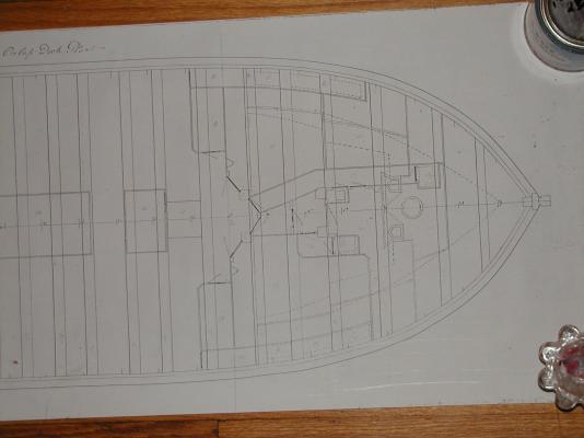
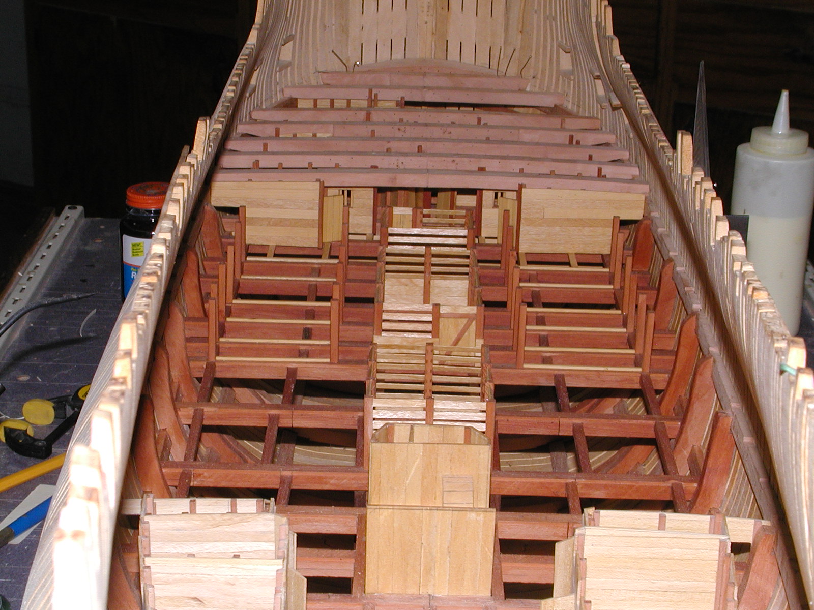
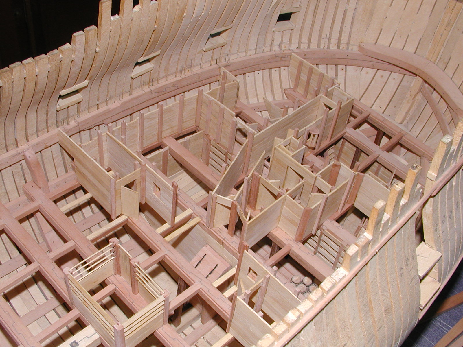
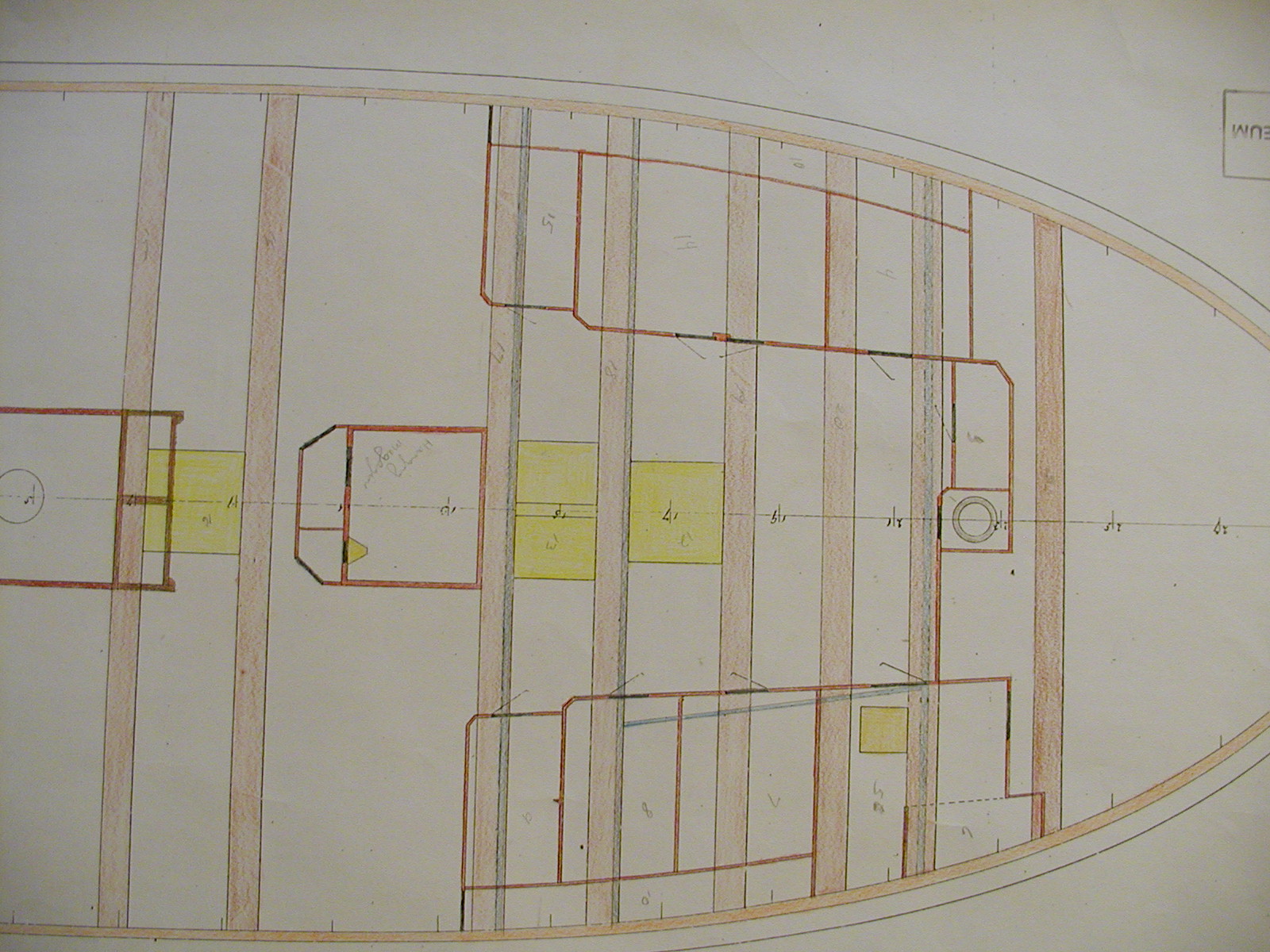
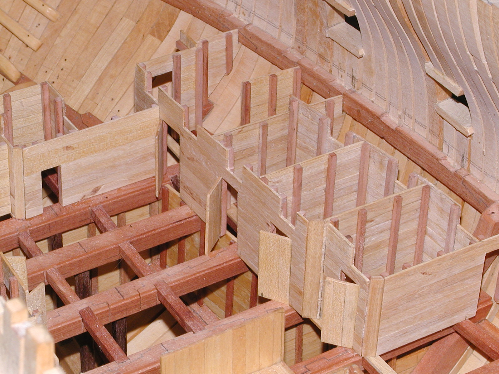
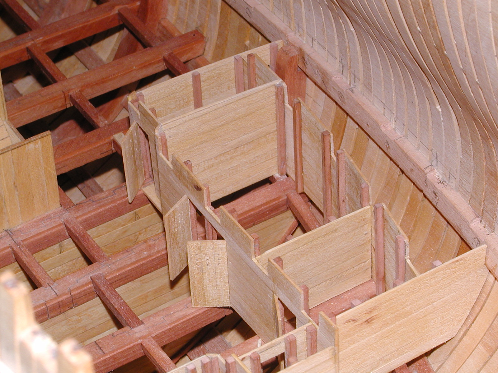
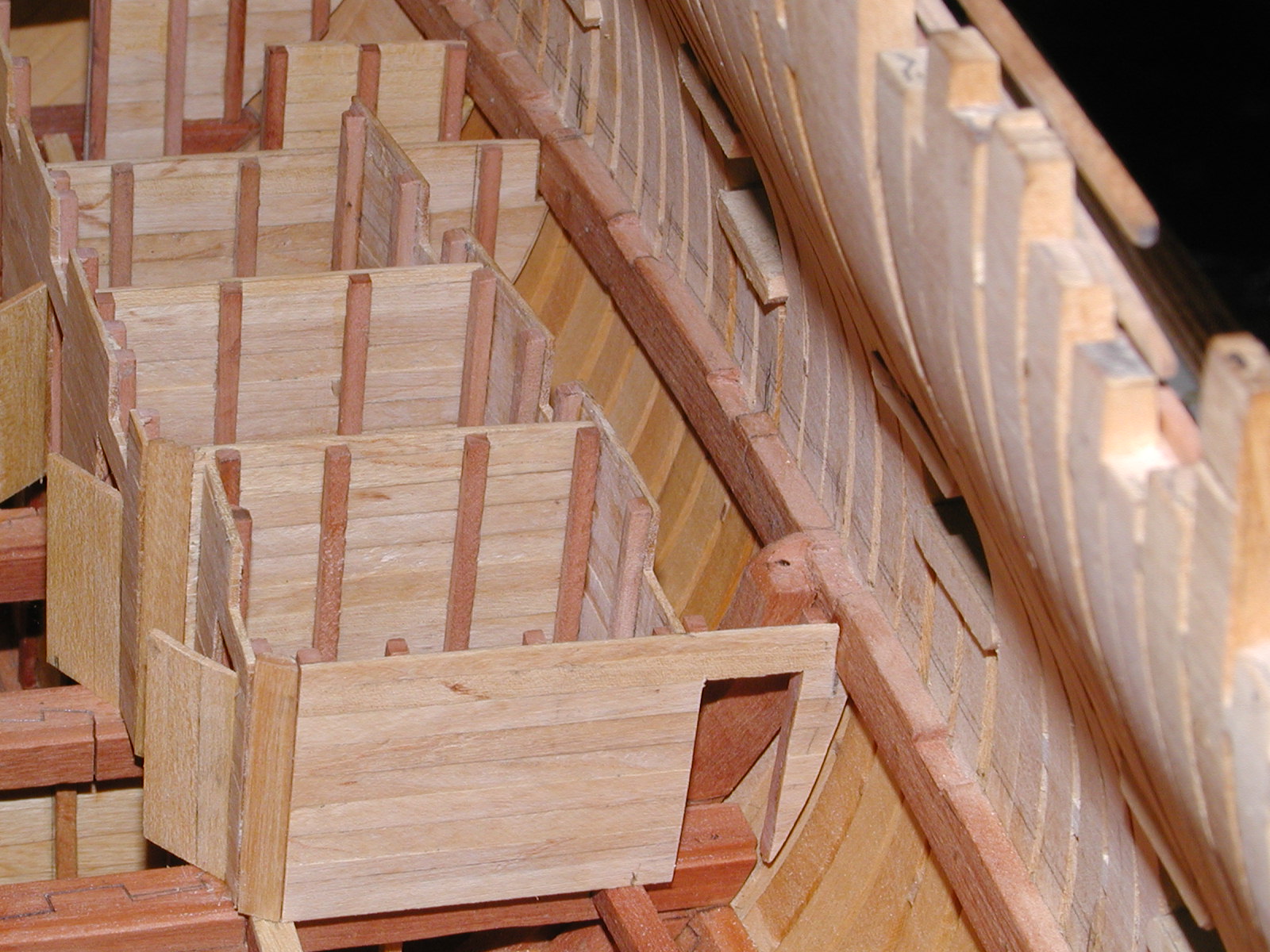
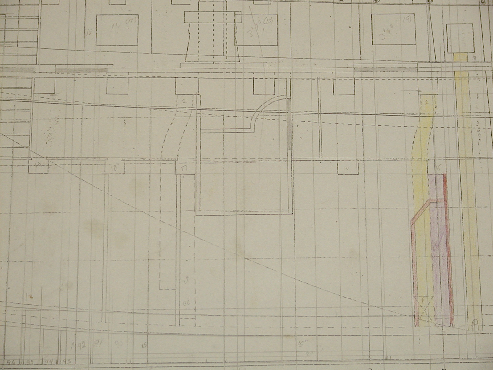
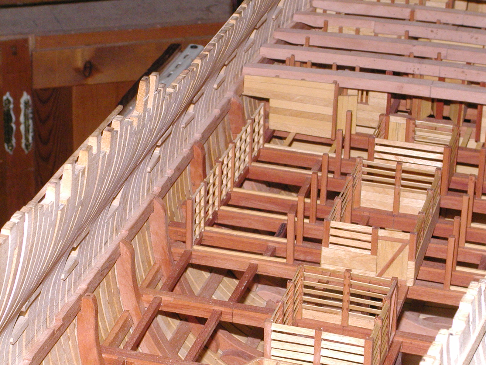
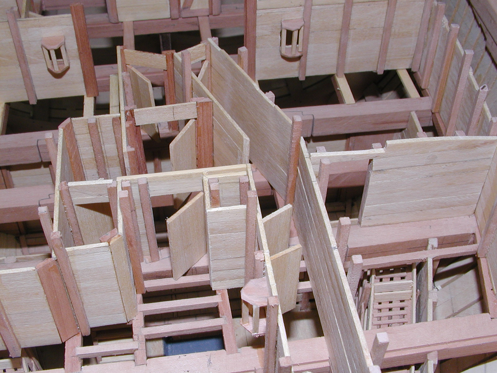
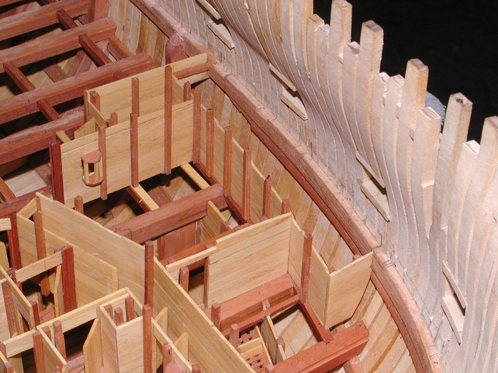
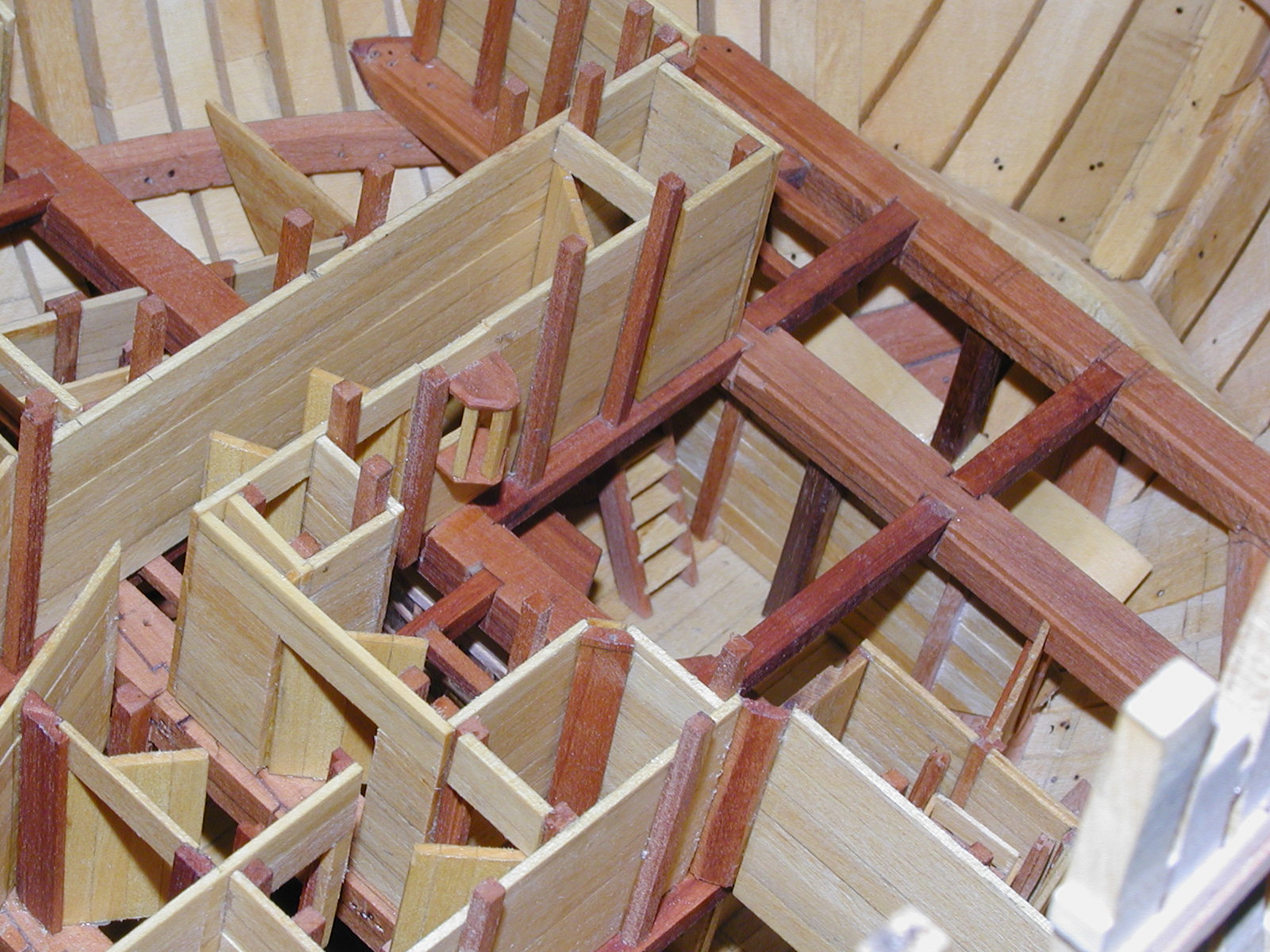
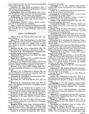
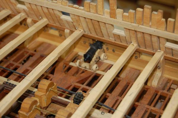
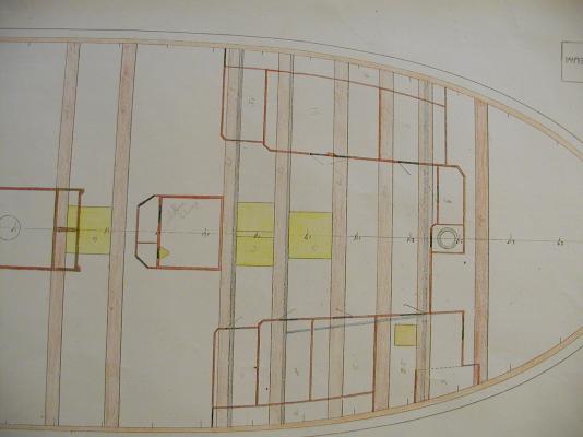
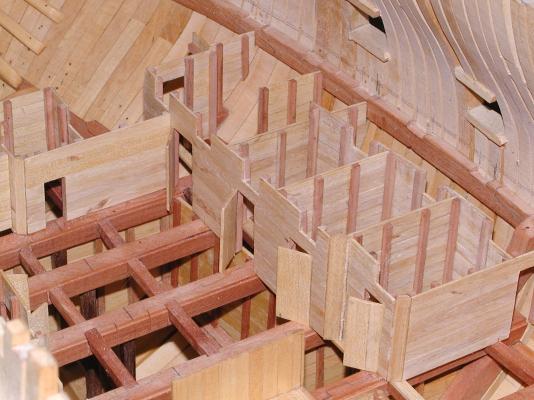
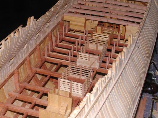
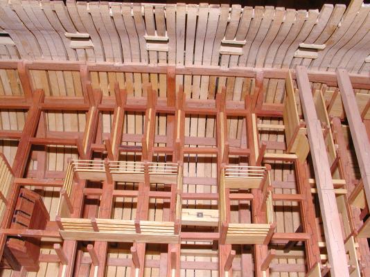
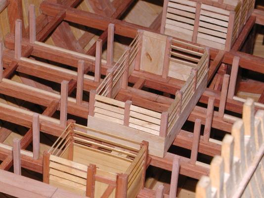
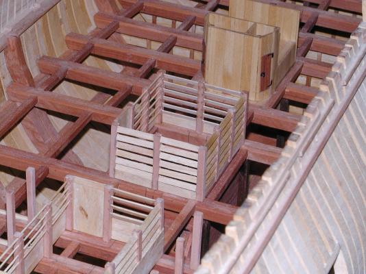
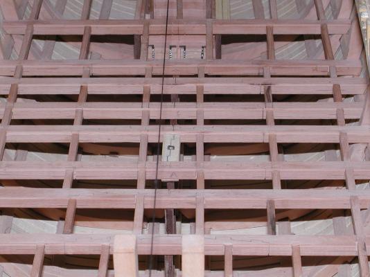
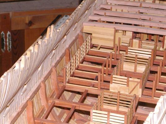
Thanks every one, hopfully many more in the future. At the moment life has sort of got in the way but hoping for some time to work on her in the near future. Thanks Ed, as soon as I get back to the cannon's I keep those sizes in mind. Daniel the carpenter´s walk did go around the orlop deck but not so much like the one you show above. There was a lot of places that was not walled in and one had a good view, of the outside wall. On 74's of Montagu time there wasn't a wall all the way around the orlop deck. Here is some photo's that show how Montagu looked. In the first picture it shows the stanchion's that separated the cable tier from the carpenter's walk, followed by the fwd store rooms and finally the aft store rooms with the carpenter's walk on the outside. Have also included the plan of her orlop deck so you can compare the two. Sort of wish I had added more of the detail on this deck,like metal work and maybe even some cables, in the tier. Of course it would have been even longer to finish this deck then the couple of years that it took. Gary


-
Hi Konstantin. Sorry sir but I can not remember were on the interenet that it came from. Doing some primary research on the round bow and came across it. Gary
-
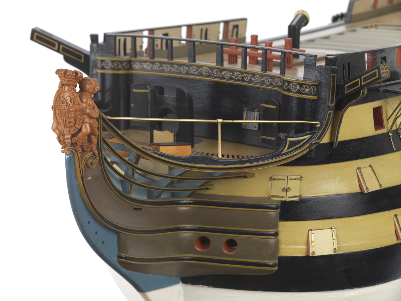
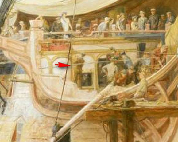
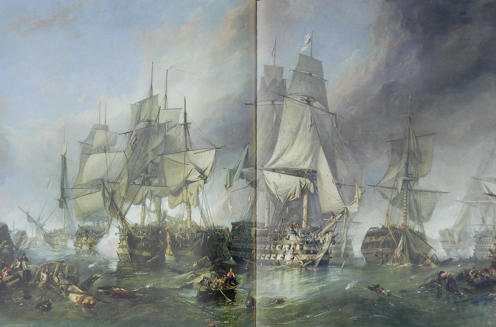
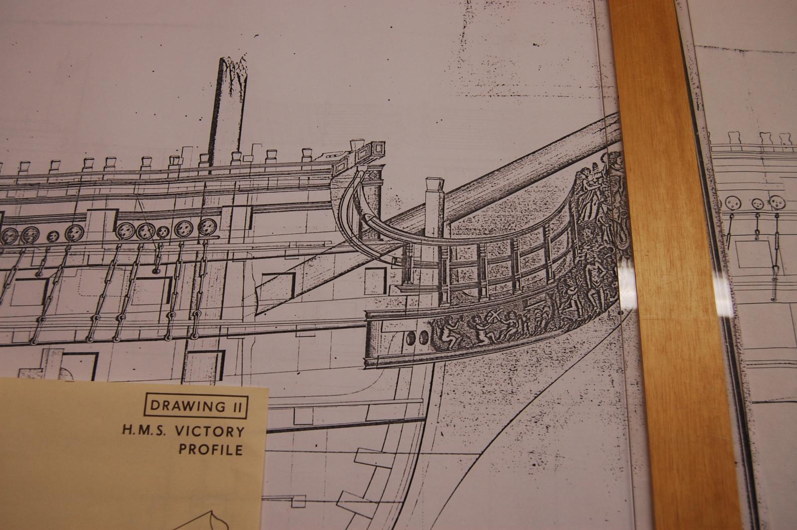
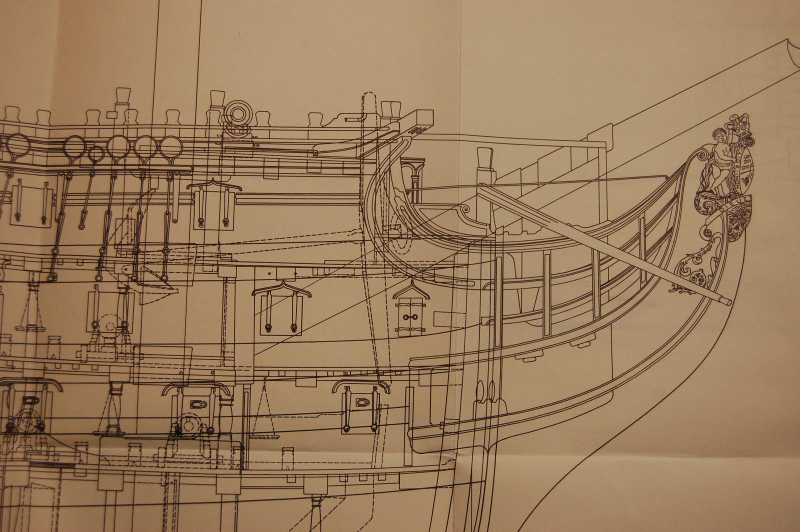
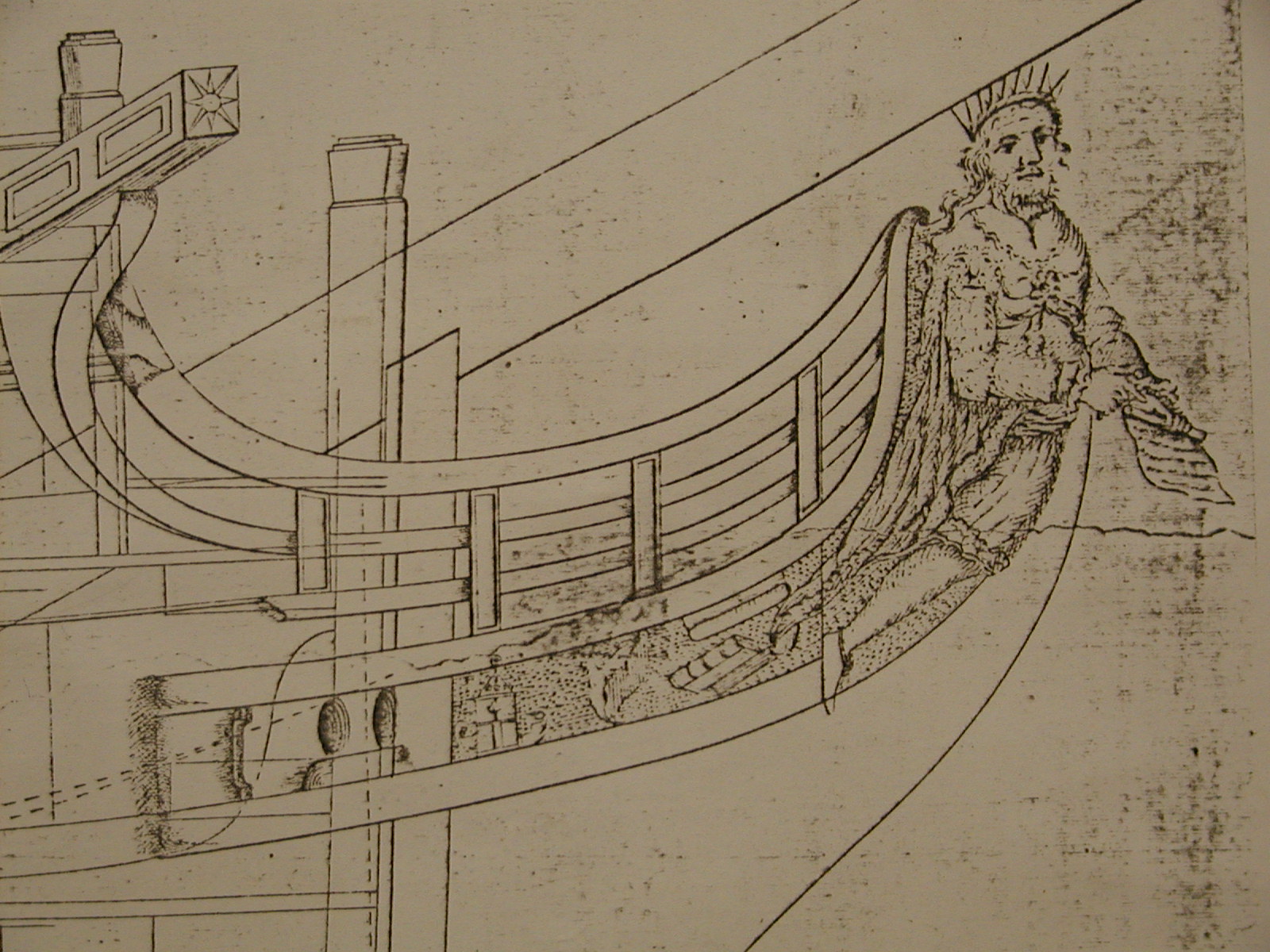
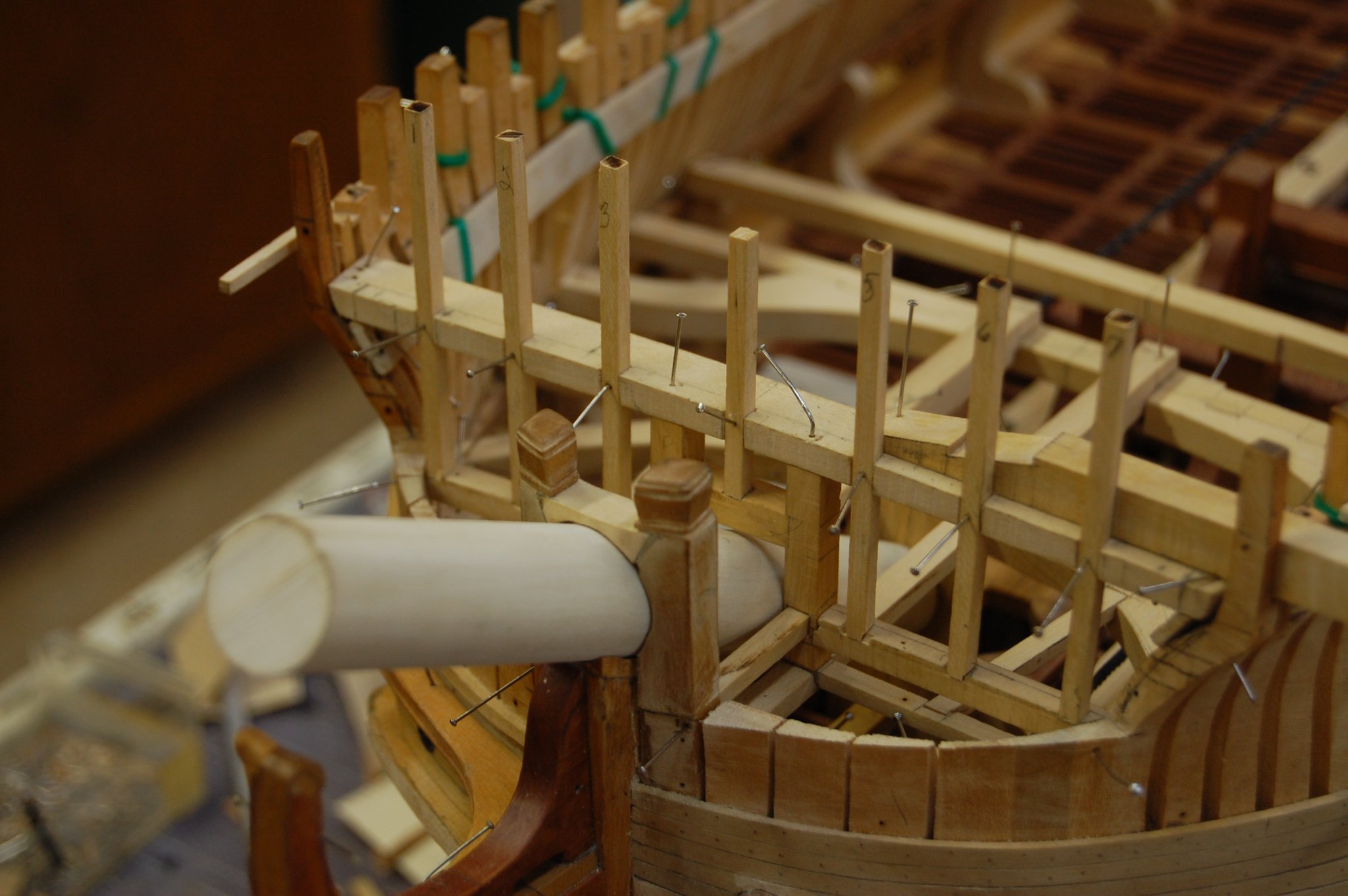
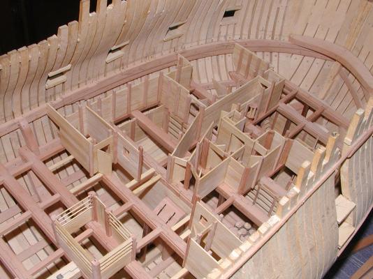
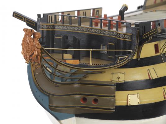
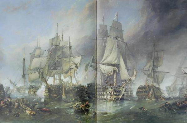
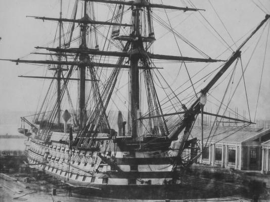
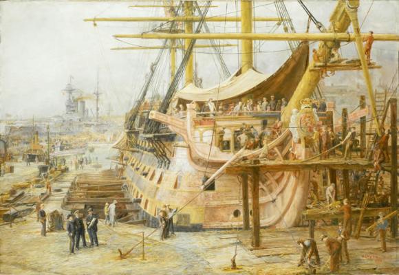
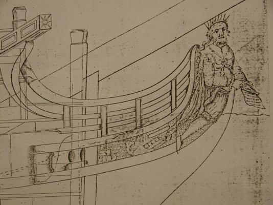
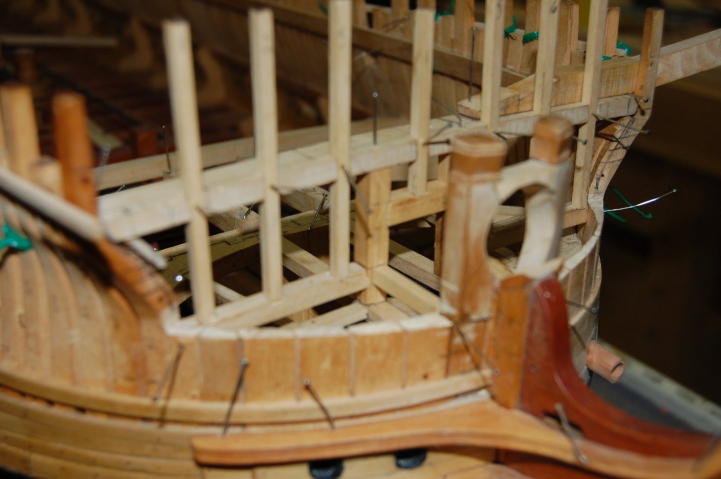
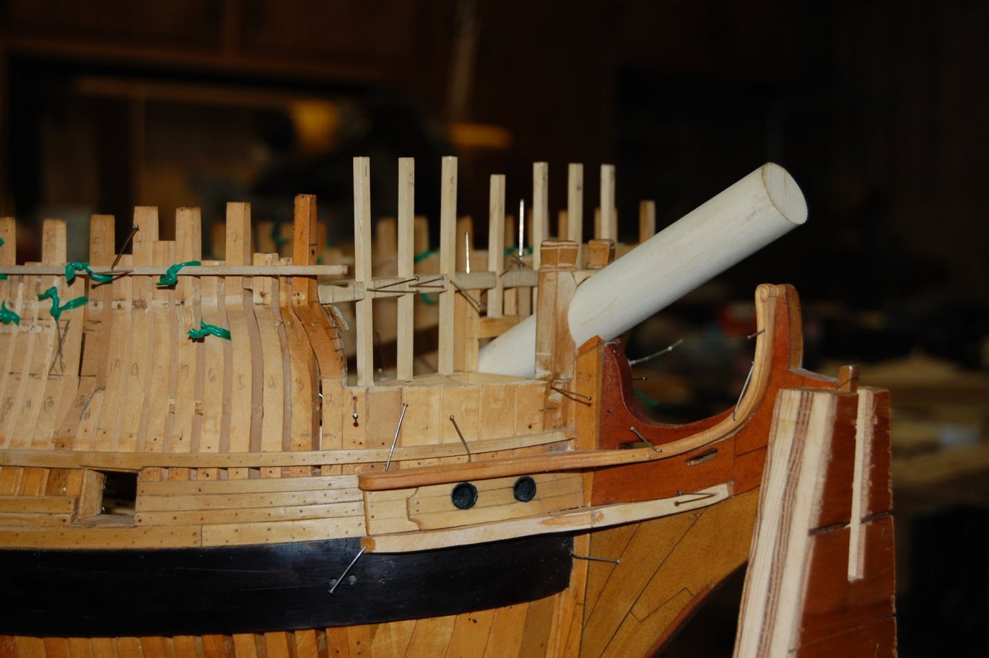
Hi Alexandru. Sorry sir and forgive me for stealing your log and after this I will not say another word on this small platform. Hi Norriro. To me the biggest question is when did Victory received this little deck and yes sir I do agree that this little platform did show up through out wooden ships. I went looking for some more primary research on this and did find a couple or is it one and some other's that are contempory. I have added 5 photo's showing the changes to Victory's bow and one that shows a first rate with a round bow. There is a picture like this one that is the Victory but I can't seem to find it now which is why I put this one here. The main one showing a model of the Victory's beakhead buckhead after she had her large repair in 1803 prior to the battle of Trafalgar, which is what the NMM web site says about it. If you look you can see the height of the chase ports from the deck. Now if you look at the painting, not sure of its date but looking at the back ground it probably was in the 1920's when she was being refit as she was post to look like in 1805. In this photo you can see that the chase ports are not at the same height as in the first picture which is probably due to the raised small platform. This is the time that I believe they strip away the round bow and tried to give her that 1805 look but the model shows what it really was post to look like in 1805. Her beakhead I don't belive is right if you compare the two. Also I added a painting not sure of the date but shows Victory breaking the French line with the same beakhead bulk head. I do believe as you said because her bow was all shot up, that when she was repaired do believe that is when she got her round bow, just like the older ship in the picture. The model also shows how the upper wale, stop short of the stem and ends under the aft part of the main rail. Could be total wrong sir but does give food for thought, and has been interesting. Thank you. Gary

-
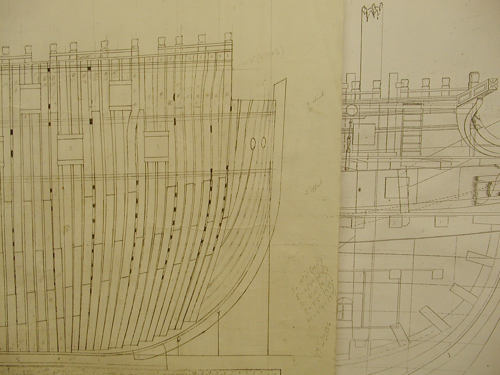
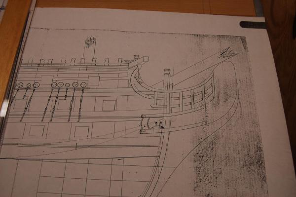
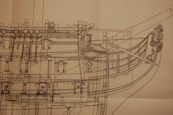
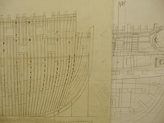
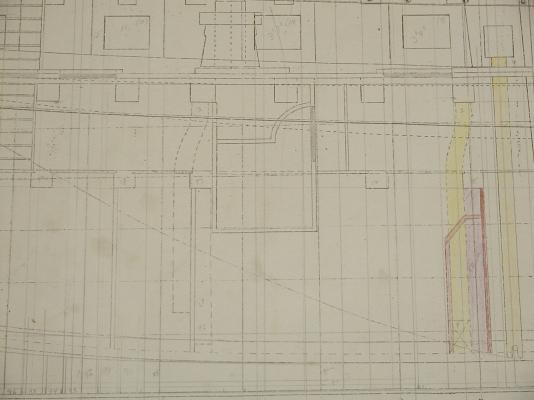
Hello Alexandru. I know this has been brought up before but just some food for thought on the beakhead bulkhead raised platform. For me I don't think that Victory or other 90 to 100 gun ships had this platform. My reason are that plans of the Victory as well as others such as the Princess Royal of 1773,Ville de Paris of 1788, don't show this raised platform. My thinking is that the raised platform didn't come about on Victory till after they redid the bow turning it in to a round bow minius the whole beakhead itself. The upper deck went all the way fwd and was even with the main rail of the head work making ever thing on a even keel. There really was't any need for this small raised platform. Once the Victory bow was redone, as she looks today, it show's the beakhead buckhead, along with the raised platform. Do believe that some of the authors that has been posted,do not show the small platform because plans and other primary reseach doesn't show this. Here are some photo's of the plans I have of Victory going back to her first drawing which came from the Danish NMM. Also one from the English NMM and one out of Bugler book. One thing you will noticed is the primary plan doesn't show the small platform. You will also notice the plan of Victory with all of her carvings also doesn't show this small deck. It's not till you see the plan by Buglar that shows this. This might also explain why the round houses and collums go down two feet more. I have also added a photo of Alfred that does show the raised platform which was a common item on ships of 74 guns. It seems that if they had this raised platform it seems that primary plans would show this. If you look in Rob Napier book Legacy of a Ship model, on page 89, 90,91 and 92 how it shows the upper deck going all the way fwd and no small raised platform. Do hope that this is some food for thought on this small raised deck that raises a lot of question about did she or didn't she. Some food for thought sir. Gary

-
Well has others have said, all kinds of things can be used for faring one's hull. I have used a drill and dremel with sand paper type flapper brushes, flat and curve pieces of wood with sand paper cement to it, metal scrapers and curved rasps. One can also use a mouse type sander that comes to a point in getting in to tight places. One item that seem to have help me a lot with fairing the inside of the bow and stern of Alfred's frames was broken glass used like a scraper. I know but it worked and didn't get cut once. Take a piece of picture glass, cover it with a towel and with a hammer tap the glass. You will be surprised at how many different shapes you will get for fairing the inside of the frames, and once it becomes dull, just get another piece. :piratetongueor4: Gary
-
Hi Jay. According to Adrian Caruana's in Vol 2 page 151/152 The 6 pounder was 6 foot 6 inches long and was a Armstrong-Frederick design of 1760. In 1787 there was also a 6 pounder that was 6 foot long and was of the Blomefield design which is on page 270. In 1809, the carron company cast a 6 pounder of the Blomefield pattern that was 7 foot 6 inches long which is on page 318. Jay as far as I know the British Admiralty didn't have control of the guns, it was the Ordnance board, so if there was any changes it would have came through them. From reading about this, at least to me it was like the navy just sort of rented the guns from them. If you was to do any searching on weapons you would have to look under the WO and if it had some thing to do with ships you would look under Adm, that is if you was to go to the Public Record's office, Kew and Chancery Lane, London. Gary.
-
Well I did find a picture of how the coat fit around the rudder head Danny but do believe that druxey has already beat me in explaining it.;o) If you look in Vol 2 of David A book you will see it on page 289. Gary
-
Russ. Do believe your right sir on the listing of the hooks. Does seem that a lot of things that was common then has become a mestery today. I even looked in Boudriot book, 74 gun ship and couldn't find the French sizes either. As far as you seeing the size of the hooks used on old blocks is probably what they were, a inch to a inch and half, and probably go with that. Yes sir it is the kind of thing one needs to know to figure out what size brass wire to use. Thank you sir for the help. Gary
-
Thanks Russ. Its a good article and the info will come in handy but one item that is not mention is the diameter of the metal of the hooks that was used. Am sure its here some place so will look some more. Do thank you sir. Funny thing is Russ, the simplest things are some times the hardest. ;o)Gary
-
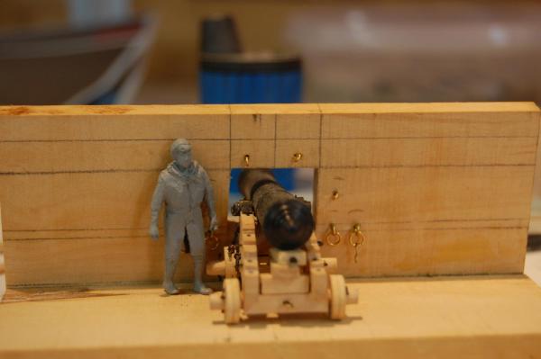
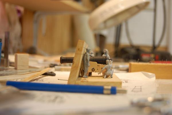
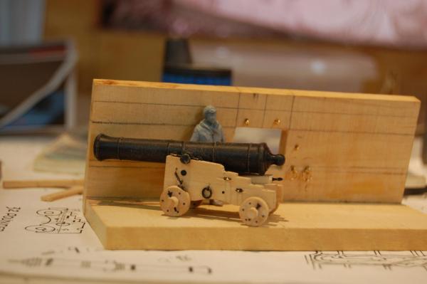
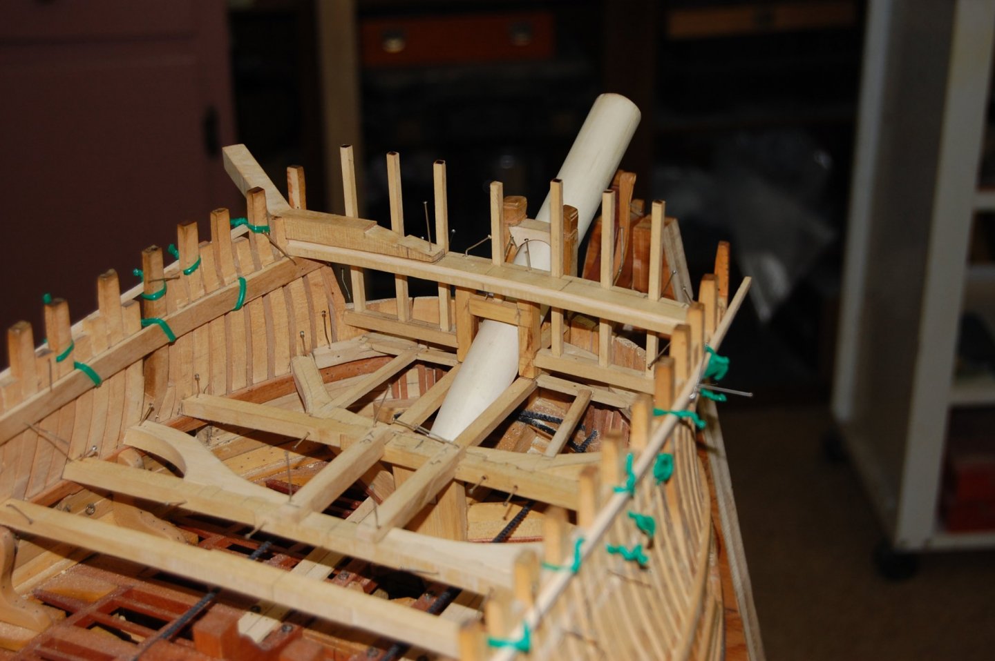
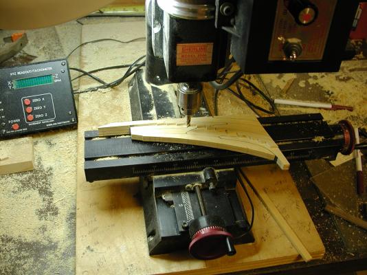
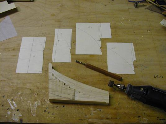
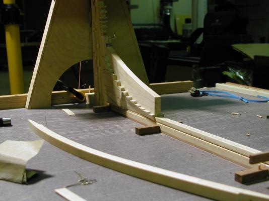
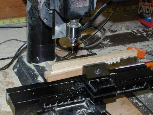
Thanks guy's. Just to let you know that Montagu isbeing worked on here is some pictures out of sync with the rest of the build photos,showing the build up of her 32 pound gun. Am in the research phase of figuring out the sizes of every thing that fits with the gun. It does seem that not every one agree's on the sizes of the fittings that fits with this type of gun. One item that I have been looking for and just a matter of time before I find it, is the size of the hooks that the block and tackle used. Just like the blocks, some say 6 inch blocks and other say 8 inch blocks, which is probably what I go with. Any way here is some photo of how the cannon looks minus the rigging which as soon as I get the right type of end mill to make the blocks, they will be rigged to the cannons. One thing is for sure, there sure is a lot of parts and pieces to them. Gary
-
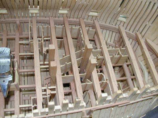
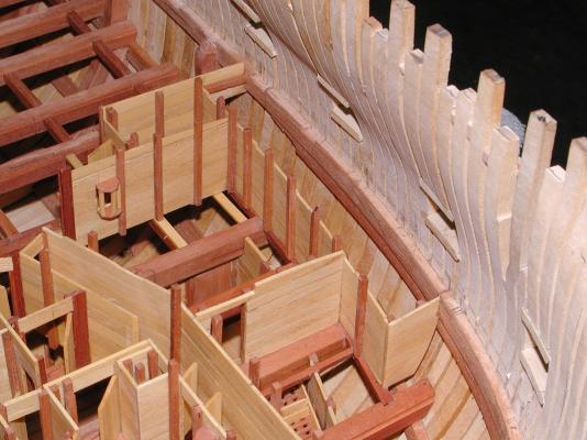
Hi Guys. Another update for you and this time as far back as we can go on the orlop, but has more to do with strengthen the transom's more then the Orlop deck. Some call them sleeper beams and Goodwin call's them transom knee's, which you can see on page 108 in his book Sailing Man of War,1650-1850.In the photo's you will also see the last beam of the gun deck along with knee's for the deck transom and the knees for the last deck beams. Most 3rd rates had three of them per side. Hope you enjoy the photo's folks.

-
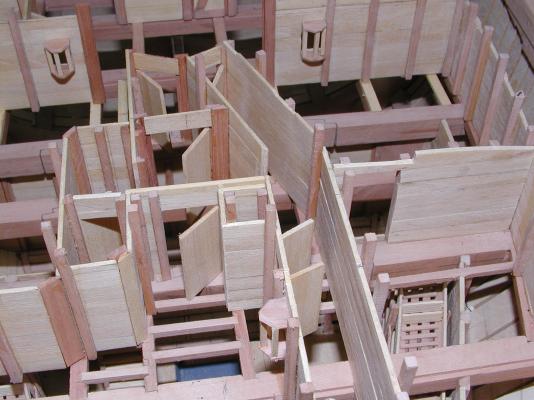
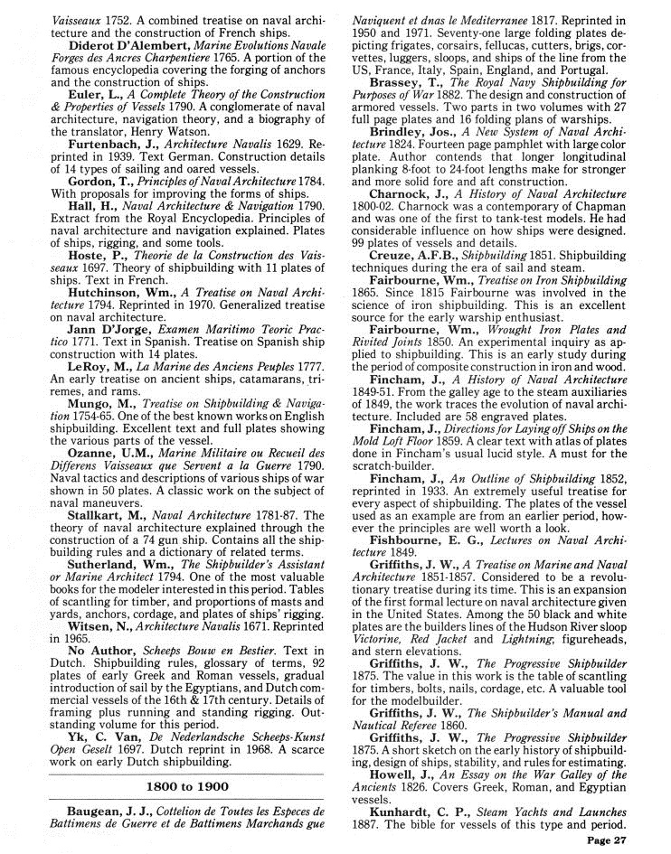
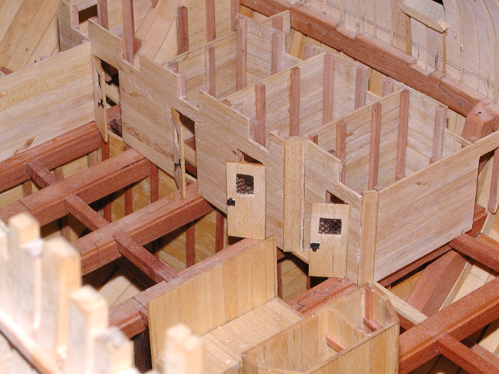
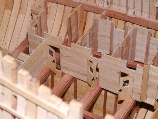
Thanks guys. There is a couple of places around here that's up for sell Clipper. At the moment the closes ship modeler lives about two hours away. Hopping maybe just maybe I can get to the NRG get together this year but will have to wait and see at the moment. Thanks Robin, I also like Ed T's build log. He has given me some great ideals that has help me with some area's that I have come across. Thanks Ed, but does seem that you are a little on the nice side but do enjoy your build very very much. Also look fwd to your next book when it comes out. Hi Guy. Your very welcome sir and if there are any other pleaces that you wish to see, just let me know sir. To show more on her Orlop deck going aft, this shows the last of the store rooms on this deck. One thing that I did detail on these store rooms was the windows and the door knobs. One can just feel how hot it got down here with only the gratings suppling air flow. Reminds me of being in the attic running circuts for some ones house.


-
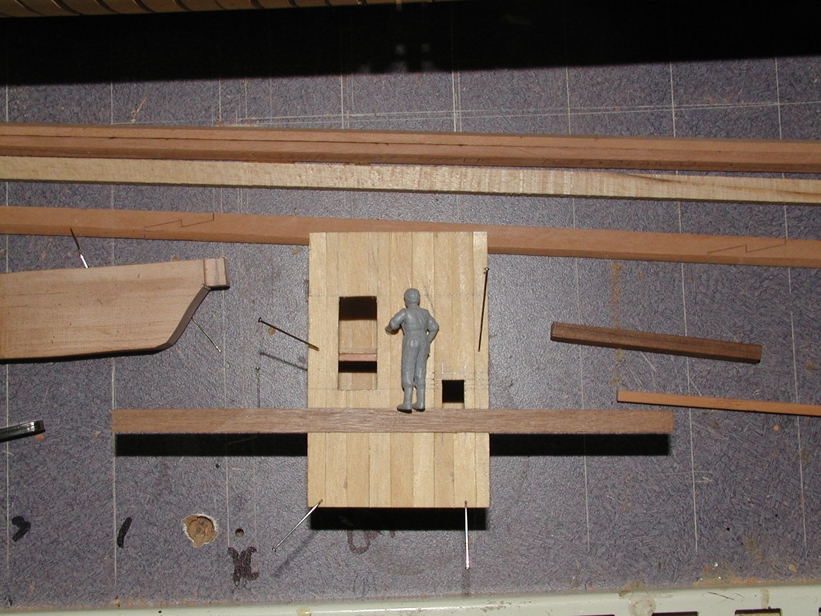
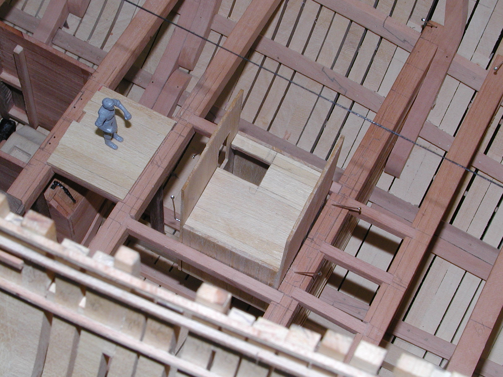
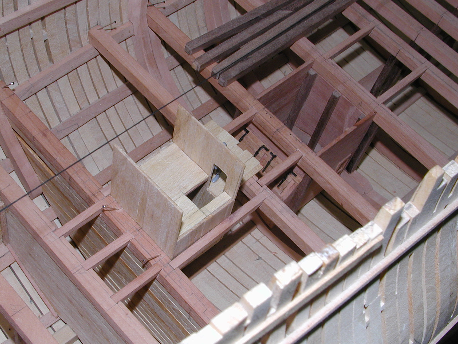
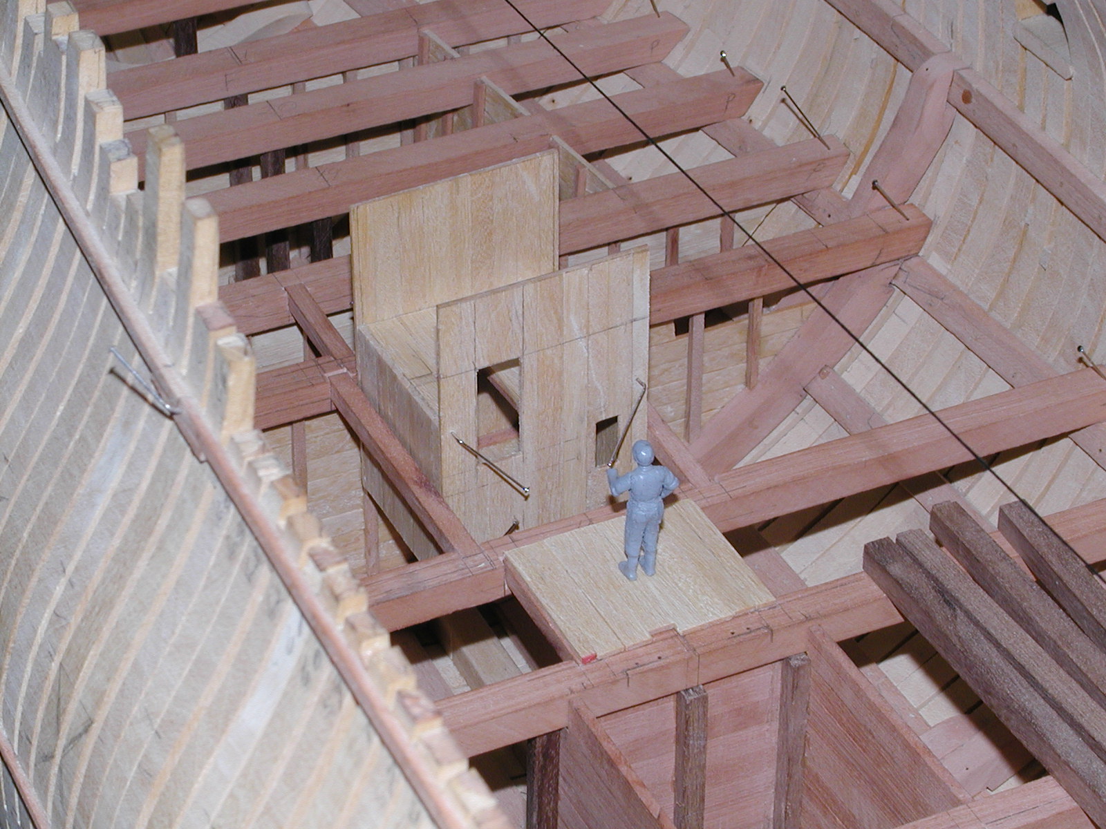
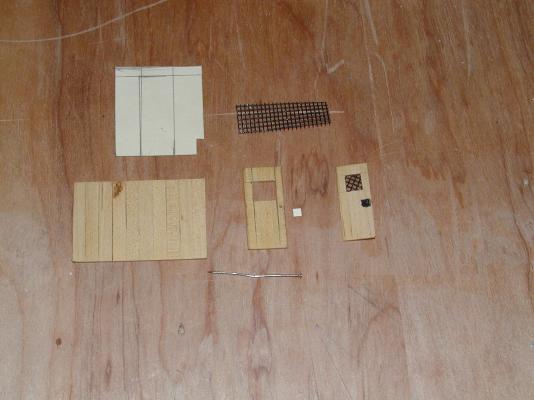
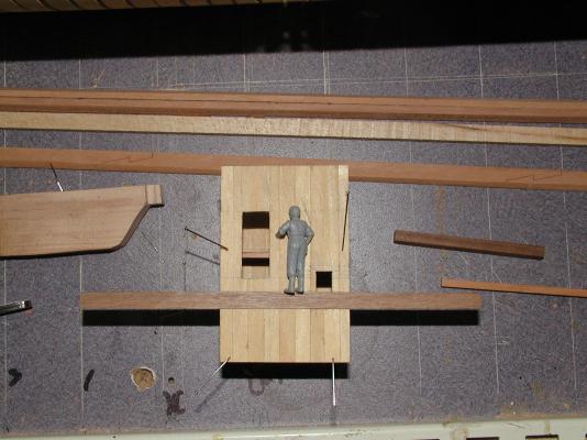
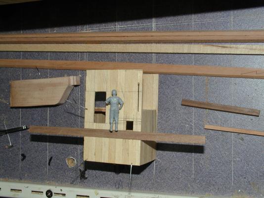
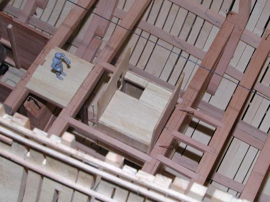
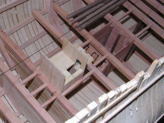
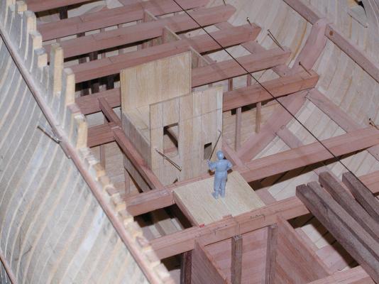
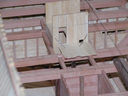
Folks here are a couple of photo's of the building of the hanging magazine. I didn't do to much detail on it but did enjoy building it. Gary
-
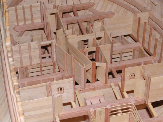
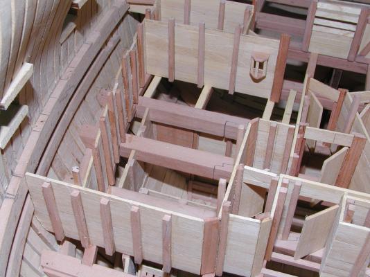
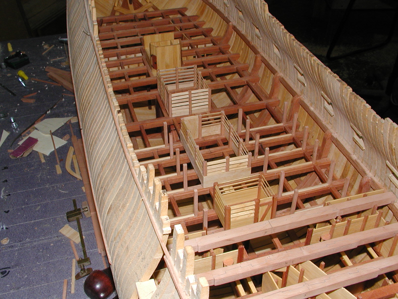
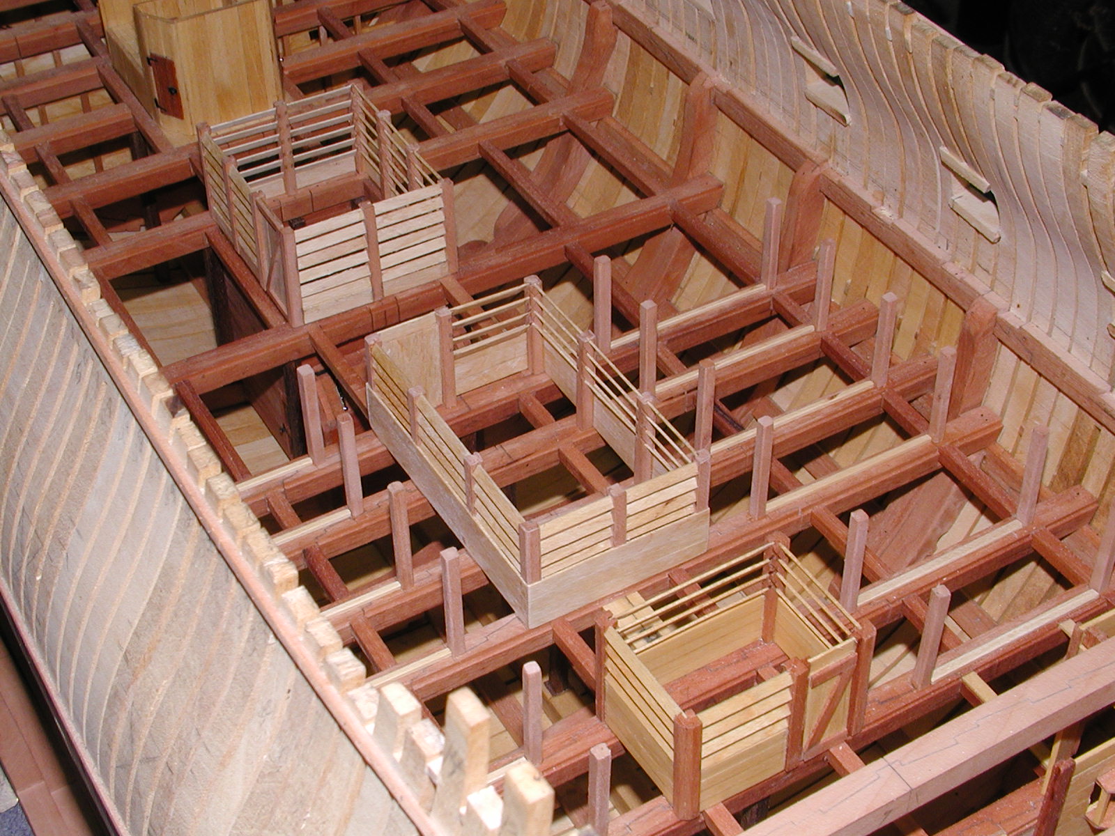
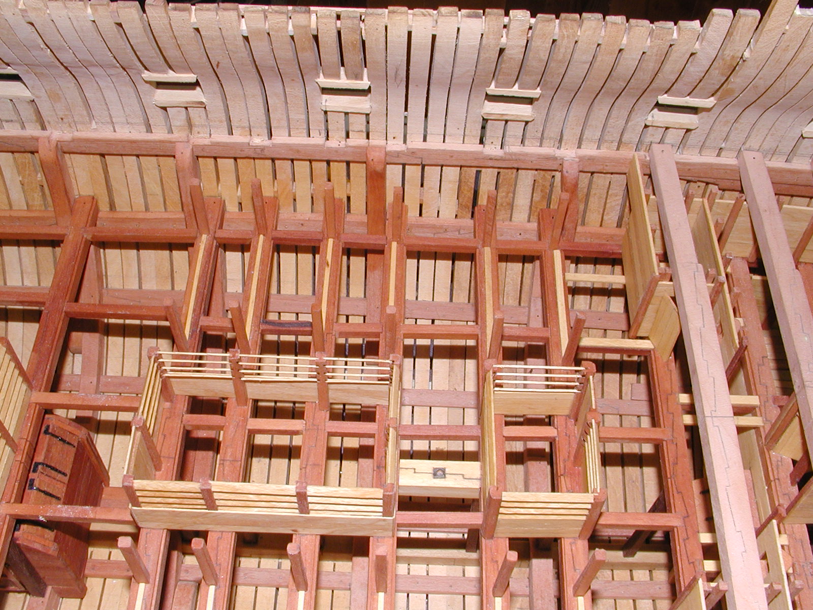
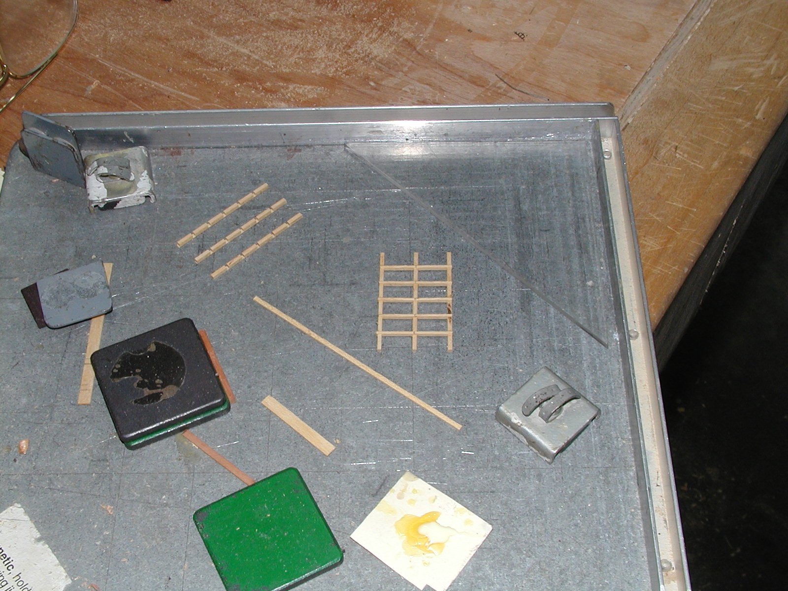
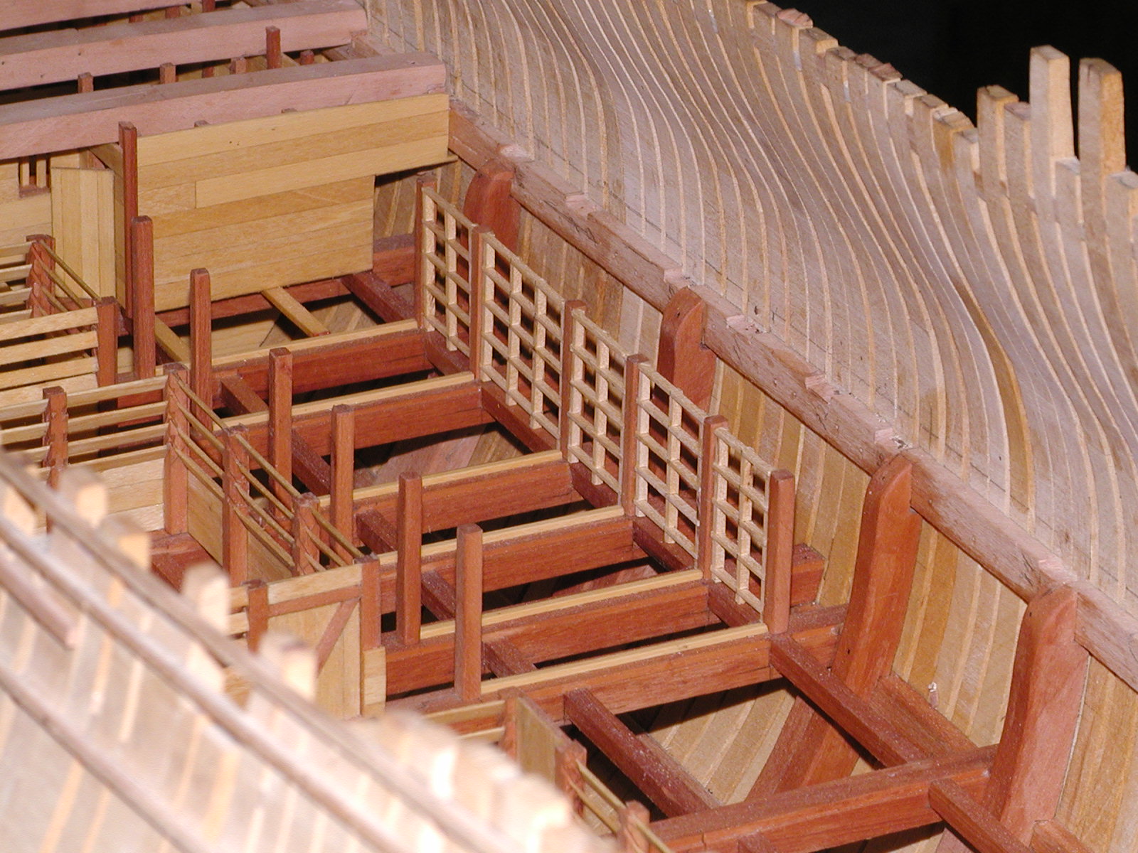
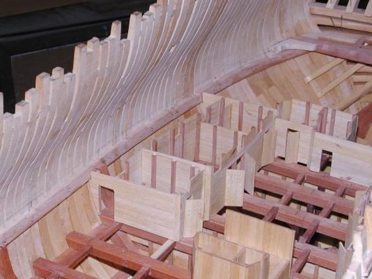
]Thanks every one, your kind words mean a lot. Here is another update on the Orlop deck going aft from the forward store rooms. One item you will noticed is the fore jeer capstan step that was fitted between the forward and aft sail rooms. Reason for the this was to enable the fore jeer capstan to be lowered down to the orlop deck making room for the long boat on the upper deck above. You will also noticed the hanging magazine, which was used to hold cartridges for some of the upper deck guns. The cartridges were made up in the magazine and then moved to the hanging magazine until needed. One of the things about this was that it was constructed to hang below the orlop deck, which I believe to keep the cartridges dry. Other items that you will noticed is the cable tier and a couple of photo's show how the grate was made to fit between the pillars, which help to keep the anchor cable contained. One will also see the shutters above the well that would some what help air flow around the timber's in a very wet area in Alfred's hold. Any question just ask away. Gary looking fwd on the orlop deck


-
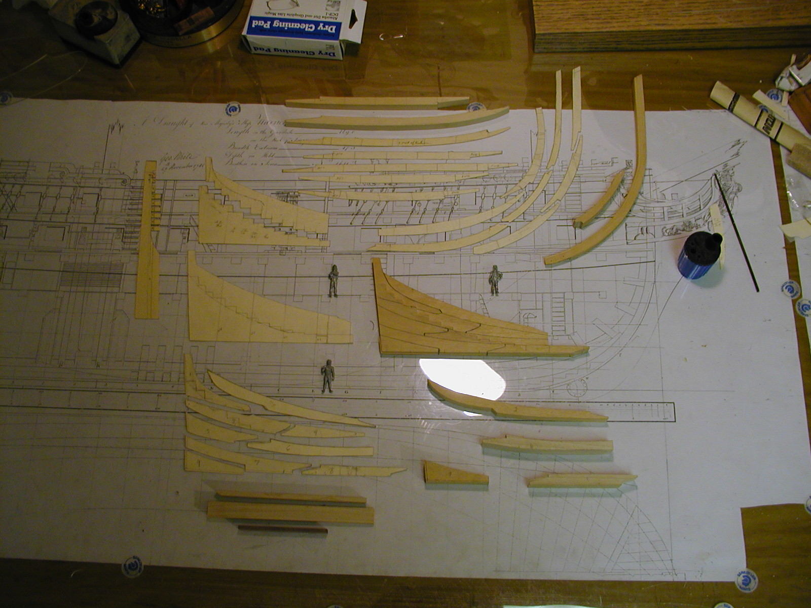
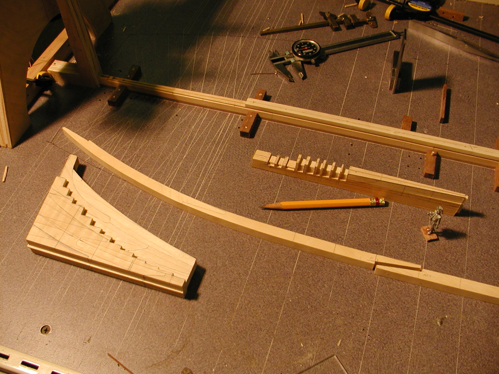
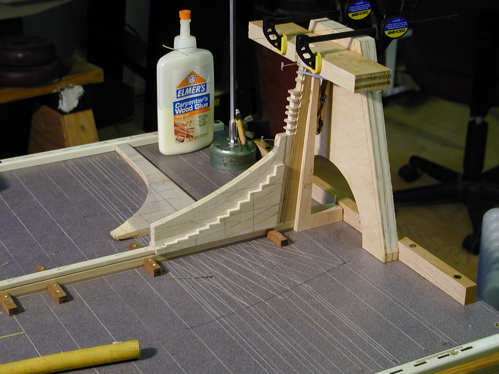
Hi Mark. As far as getting both sides even, the template helped with that plus lines that were marked across the top of it. Believe it or not that was one of the items that worried me the most and after carefully marking it out worked out fine. Thanks Joe. Have been a little slow at posting due to life getting in the way along with the Honey dues, such as flowers and yard work. One must keep the misses happy which in turns keeps me happy. ;o) Hi Juergen. Sorry about the delay sir and thanks for your kind words. Here is a couple of photo's and hope they help you on the wale at the counter. Hoping I get around to posting more in the very near future. Gary
-
Hi Daniel. Always amazied at your build of the HMS Victory and how much scratch you put in to them. Did you every think about putting in all the tools used to handle the cannons? At the moment am researching the tools and were they may of been put. I know that some times the were hung on hooks on the bulwarks and some times on the beams them self's. Seems that the beams them self would have been a little on the busy side with the pieces that held the hammocks. Any way can you please tell me were you got the photo etch that you have shown in the last few photo's of your build. Thank you sir and look forward to your next surprise and update to bring her to life. O am always happy to see that your crew are hard at work. Gary
-
Seems that the 1719 Establishment list may be of some help here. You can see this in the back of Peter Goodwin's book Sail Man of War, page 241. Her main gun deck ports were 2ft 4inches. The middle deck gun ports was 2 feet 2inches. Her upper gun deck ports were 1 foot 10 inches. It probably was from the top of the deck plank to the top of the cill's. The main gun deck plank was 4 inch thick, the middle deck planks were 3 inch thick and the upper deck also 3 inch thick. On the quarter deck the plank was 2 1/2 inch thick and the cill was 1 foot 7 inch's. The reason I say the 1719 establishment is what David Lyon said in his book, The Sailing Navy List. As a ship that was generally [sic] approved of her dimensions were taken for the 100 gun ships of the 1719 Establishment. Her great repair of the 1720's is counted as producing a new ship by Lavery. Gary
-
Turning cannon's
garyshipwright replied to garyshipwright's topic in Metal Work, Soldering and Metal Fittings
Thanks guys for the response. Just a little in site in to why I ask about how others are making their cannons. If you guys don't mind could you show some photo's of your cutting tools before and after. Maybe in the future some one will show how they did this from start to finish, on cutting the shape in to the tools to blacking the cannons, sort of like a practicum on making cannons. Making one cannon isn't to bad but 74 of them that look alike, ;o(. Any way thanks guys. I have turned cannons before, but have allways been impressed by some of the outstanding work on making cannons such as Alex, and really looking on trying to make a perfect cannon, if that is possible for me. Gary -
Turning cannon's
garyshipwright replied to garyshipwright's topic in Metal Work, Soldering and Metal Fittings
Hum, figure for sure that some of you turned your own cannons but guess not. O well thanks anyway. Gary -
Hi Every one. Just a question or two. What tools or more like what shapes are your cutter's and how would you go about making them, to be able to shape your cannons? Look fwd to your reply's, and thanks in advance. Gary
-
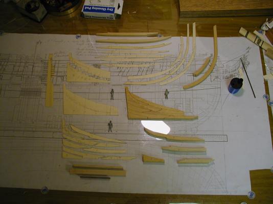
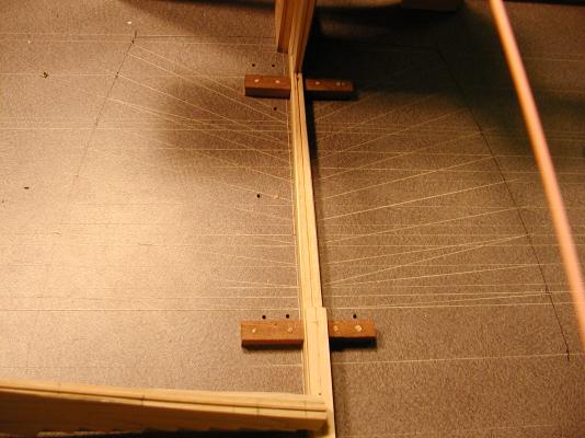
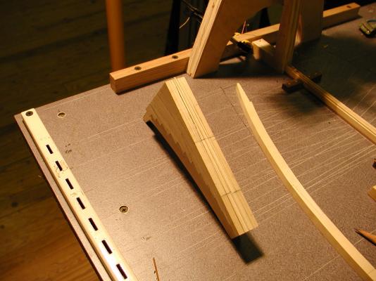
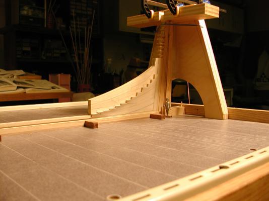
Hello every one and thank you very much. Sorry about not getting back to you sooner. Hi Guy. Seems my log is a whole lot shorter sir and seems that I didn't put in any photo's of building up the stern dead wood. I do have photos showing the templates of the parts and pieces and how her stern deadwood was mounted in a groove that was milled in to the last piece of her keel. there was a male part to this cut on to the bottom of the dead wood itself to help me align this so it would be center on her keel. Hope you enjoy them sir. Seems I just may have to look and see what other items I may of missed in rebuilding her log and thanks Guy for letting me know about this one.


-
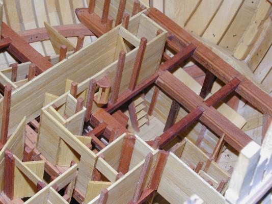
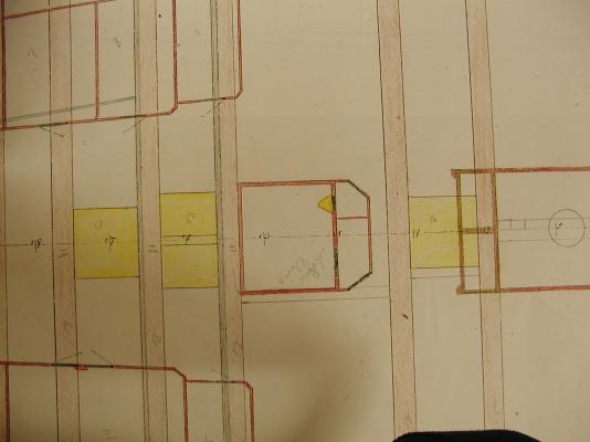
Thanks Guys. Here's another update and this time we head back fwd on the forward store rooms. It does look a little confusing, but have added a layout of her store rooms. If any of you have any question's but take a look in Peter Goodwin book the sailing man of war, page 113 fig 4/2. A couple of items in his drawing and Montagu are diferent. Item-A is really the scuttle going down to the main magazine. He call's it the cartridge scuttle which was really on the port side across from the scuttle going down to the main magazine and access to this was in the passage way to the light room. Enjoy the photo's