garyshipwright
-
Posts
937 -
Joined
-
Last visited
Content Type
Profiles
Forums
Gallery
Events
Everything posted by garyshipwright
-
 Looking good Ed. She has come a long way since you started her. Seems that am going to have to get some more popcorn and take a bathroom break so hold on till I get back. Wonderful build Ed. Gary
- 3,618 replies
-
- 2
-

-
- young america
- clipper
- (and 1 more)
-
Hi Rusty. If you go for the 17" you just might want to look in to getting the power feed. Saves a lot on the wrist. You could always get the 8 inch and then when you really feel like you need the 17" bed, you can always upgrade it at much smaller cost, that is unless you can talk Sherline in to a good price on the 17. Gary
-
Thanks Jesse, but you have no reason to be jealous sir, its more of a love of building them and making all the parts and less on the talent side. Gary
-
Thanks Guys. I do believe that all of it will come in handy and thank you very much. If you have any more it not only will help me but some other poor lost soul trying to find his way home. Gary
-
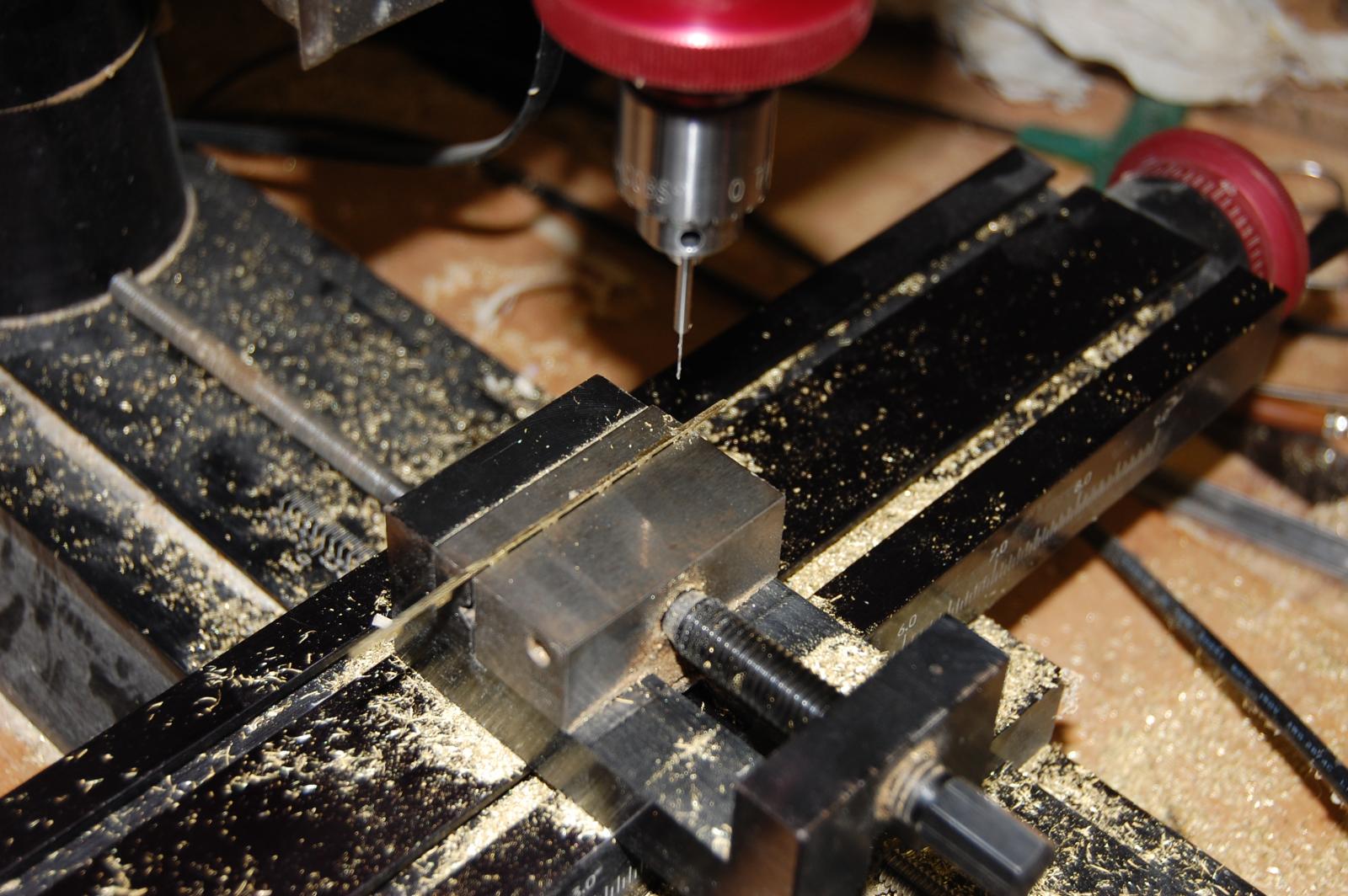
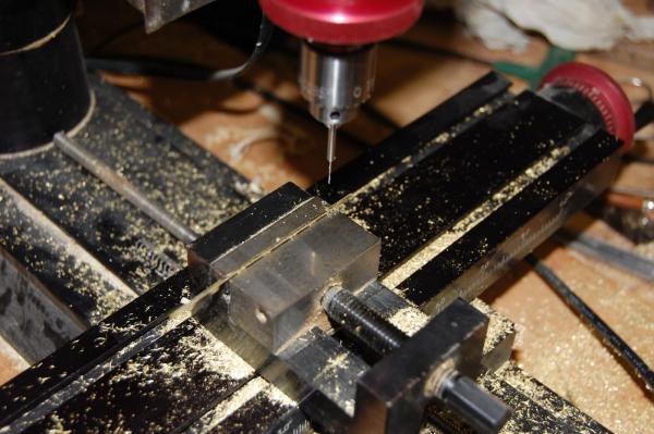
Thanks Guys. As far as being powerless Alistair, when I started out, believe that a dremel tool is all I had. I did make a thickness sander out of a table top belt sander. Took the shaft out and had the machine shop thread one end for a drill chuck, to it to hold sleeve's for round sand paper. It does seem that if I had not seen a article about punching holes in a B17 with one, I probably would be with out one. I did add a drill press for the dremel which was really my first mill. Used it for years. One tool that will make life easier in our hobby Alistair is a small table saw. Guess I could go on and on in the tool's but they do make model building a lot more interesting. Hi Remco. As far as super glue goes sir, I do use it but most of the time just to hold metal in place untill I can drill holes for the peg's. Seems that it just no fun when a part comes apart just when you don't want it to. As far as the sensitive drilling attachment, have to thank EdT for that one. I give him a hug if I could. If he had not been using one in his Naiad built, never would have thought about it. It has allways been a problem for me of breaking very small drill bits in metal. Most of the time using the column doesn't give one any feel for how much pressure one is putting on the bit, and for me as always been a pain in the wallet due to breaking drill bit's. I am finding that I break a lot less but I do still break them. Will be a very good addition Remco to you milling. Hi Robert. The drill bit in the photo comes from http://www.contenti.com/index.html I purchased 6 bits from them with the 3/32 shanks in the 0.5mm and the 0.8mm size. What makes them nice is that they have just a little flex when starting the hole unlike the carbide bits. Cost a little bit but saves money if you don't have to buy as many. I also went and purchase some solid carbide bits, .018 also with the 3/32 shank, 50 of them, just in case I broke one or two. Cost about 20 dollars. These came from Drill Bits Unlimited.com Much nicer buying what you need instead of the kit with all the different bits. They do seem to break easy but are used mainly in the mill, help's me from breaking a lot. You probably already know about getting bits from Micro Mark and Model Expo. Those I get for general dilling in a dremel tool for holes in wood. They have a good price for the amount you get and don't have to many break. The sizes I get usually come's in the 62 and 63 size. About 10 per tube. Most of this you probably already know Robert so just forgive me on that. Thanks B.E.You can comment on any thing you want sir and the information is always helpfull. Have to agree with you about the lower ports being closed most of the time out to sea unless of course they was going in to a fight. Being the lower ports was only about 4 feet or so above the water, would not of taken to big of a wave to cause a big headack. I will have to take a look at John Harland's book, just in it the other day looking for information on messenger's size. Thanks druxey. Figure it was time sir to really work on my metal making and after seeing Archjofo in his La Creole build. was taken over by how great his metal work really look's. Guess he is to blame for the push to go deeper in to metal work on Alfred and for this I thank him. Thanks every one. Gary
-
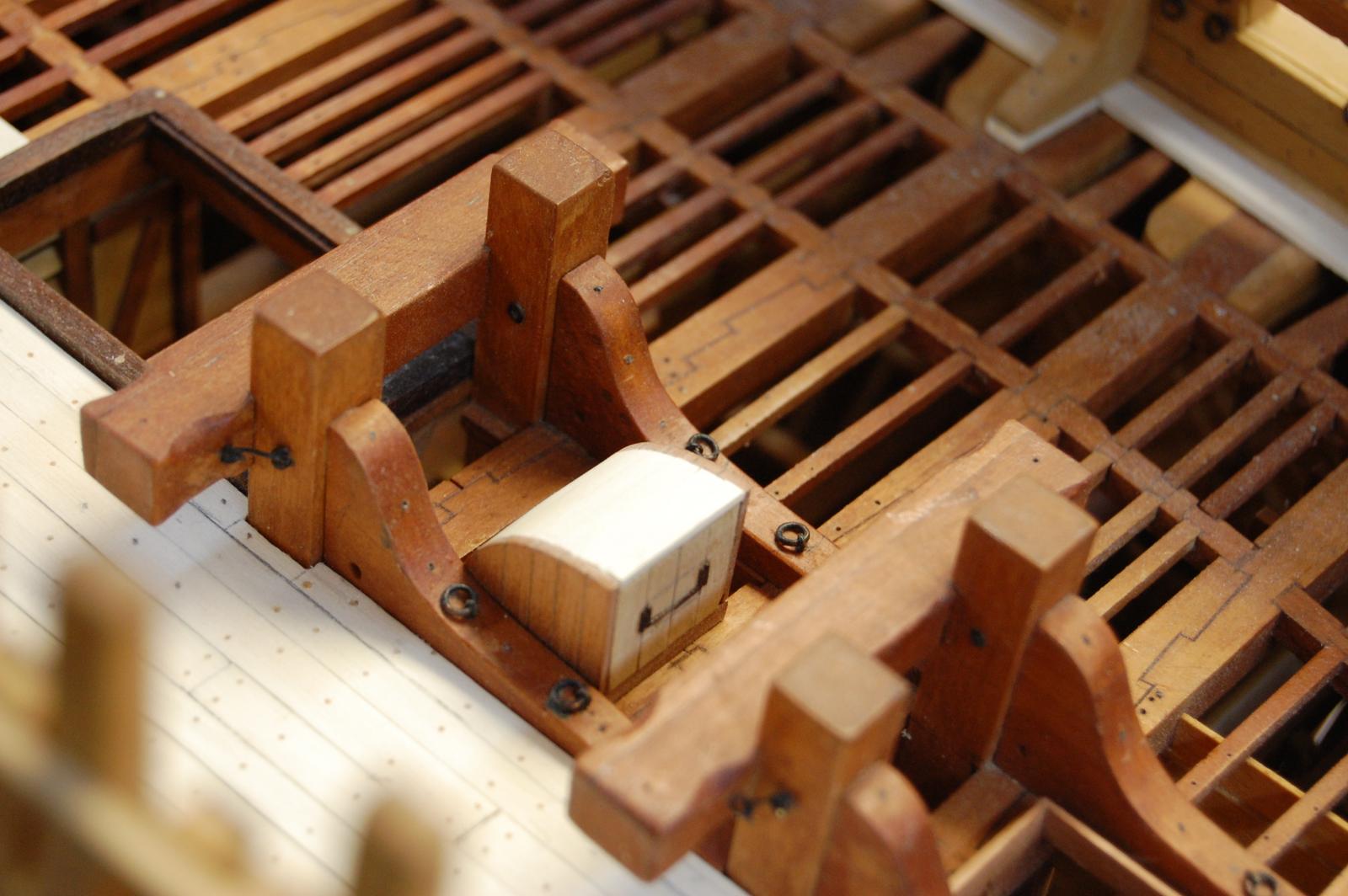
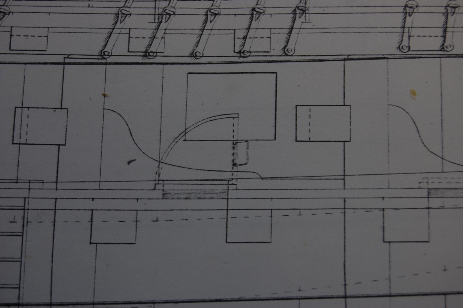
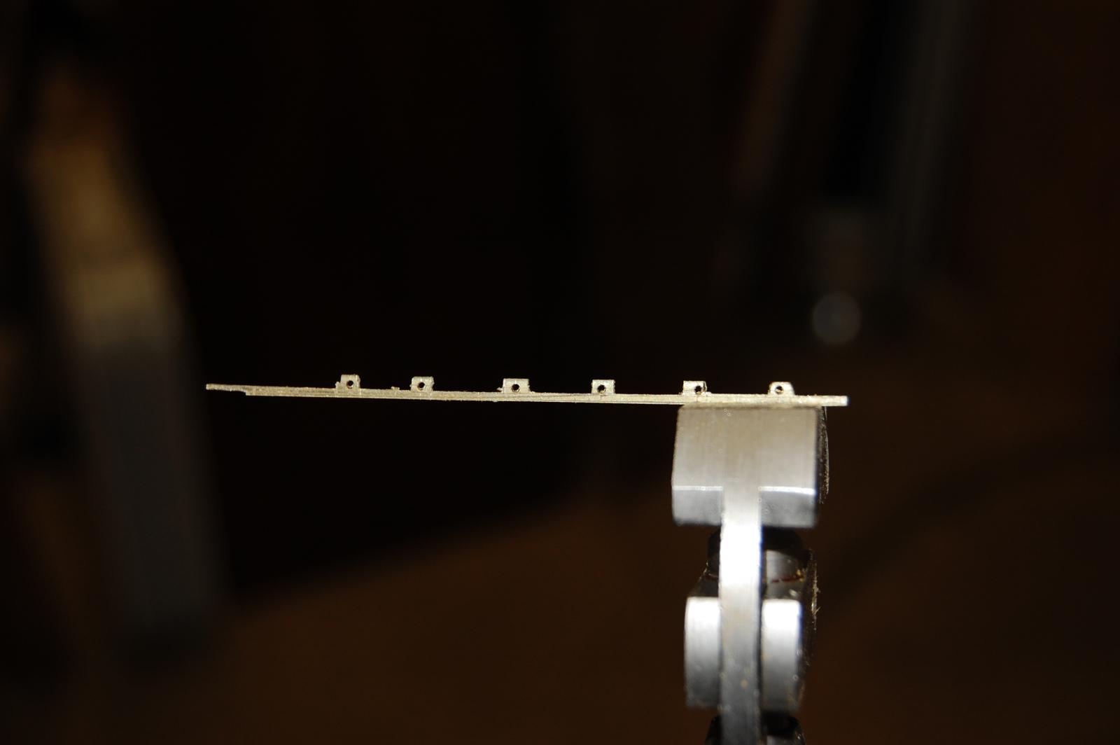
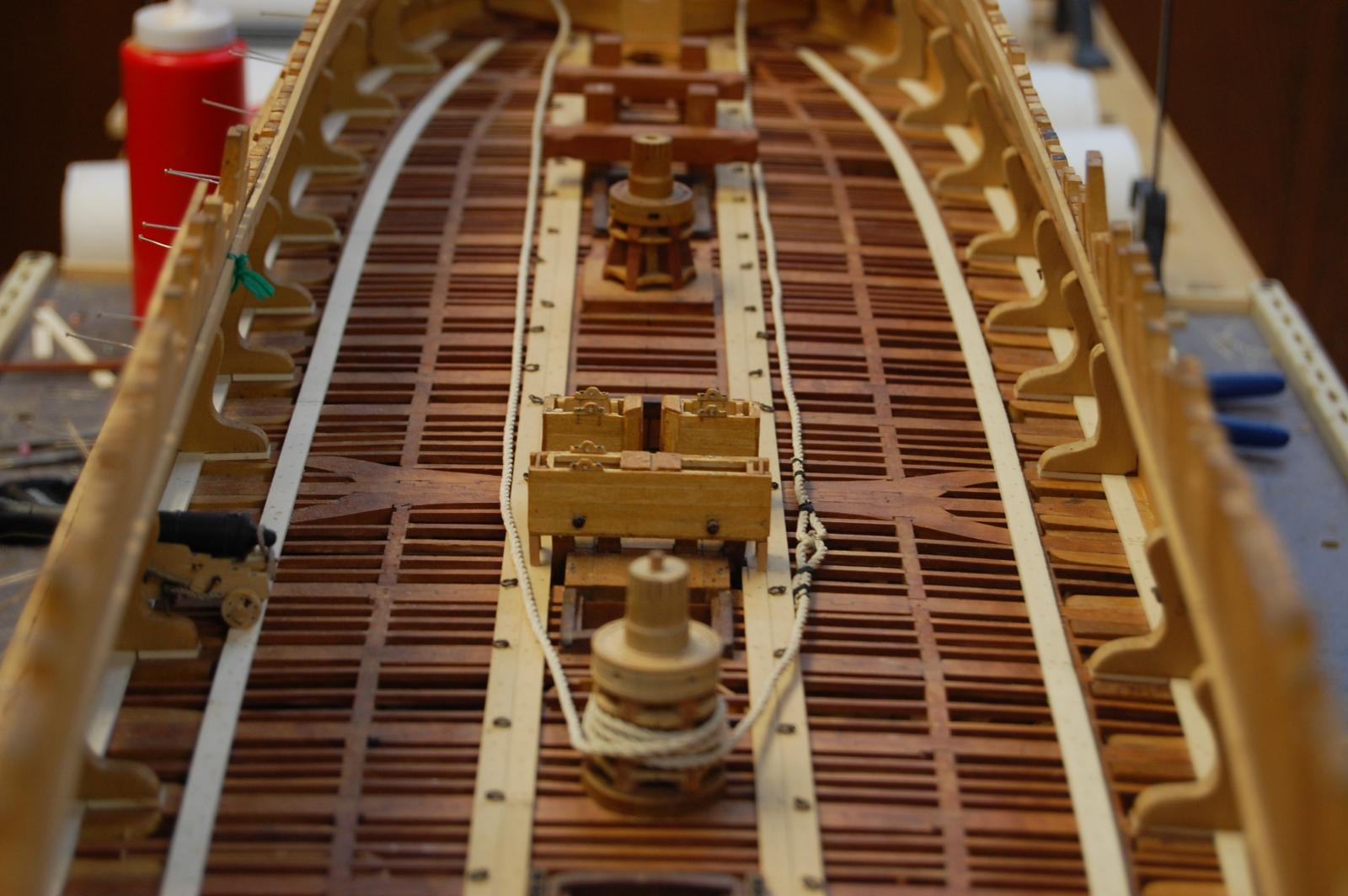
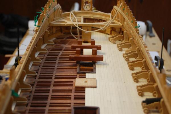
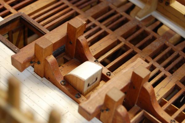
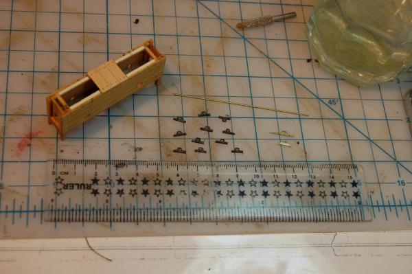
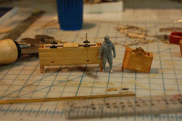
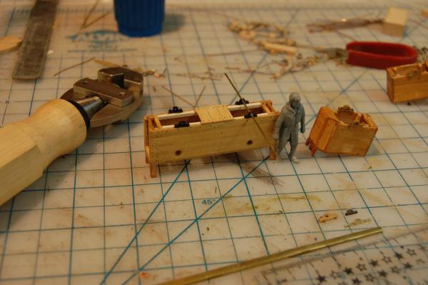
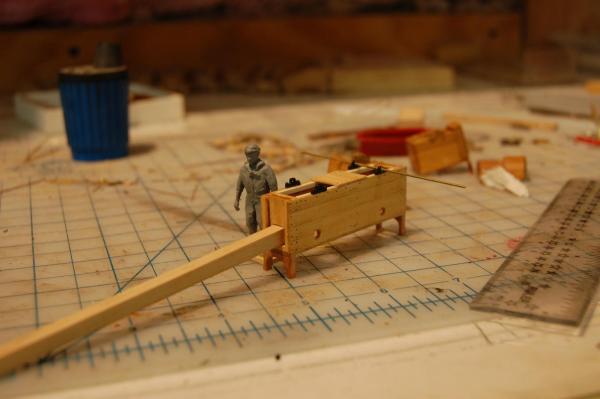
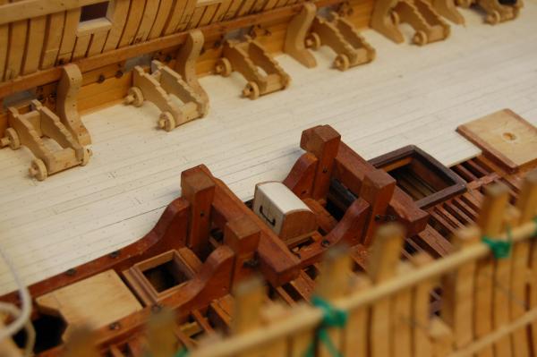
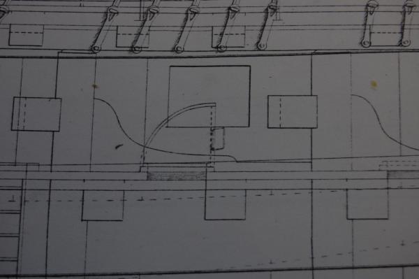
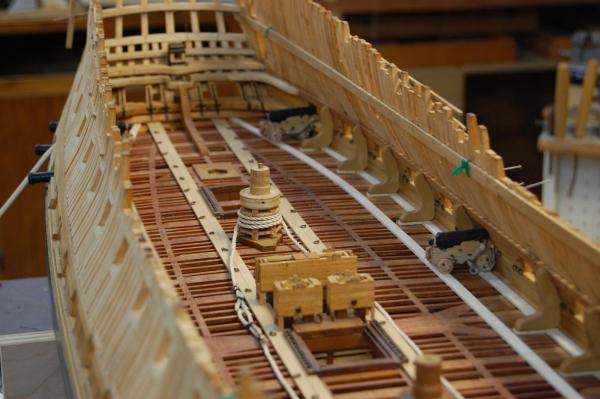
Hi Alistair. Your very welcome sir. At the moment am still probably go with the frapping and some gun's in different placement like being tied up but that is hopfully in the near future. Have a small update guys. The planking of the gun deck is finish and should not be adding any more at the moment. The Captain did come around and talked about overhauling the pumps and bearings and a few other things. The old bushing set was wooden, and figure I would try to make some metal ones. Figure that if I don't work more with metal, won't ever get any better at it. Do believe I finally figure out and got myself some good drill bits, for drilling very tiny holes in metal. With the sensitive drilling attachment it helps me big time, from breaking a ton of the small bits. Any way I milled out the shape of the roding's, believe thats what they are called and drilled the holes for the bolts to keep them in place. The pump housing tubes and main mast partner was taken out and given a new look and then reinstalled , the partner and pump tubes that is. Also added the aft scuttle hatches with the cover some what just sitting on the bottom half. Now I did come across a item and thought it would be nice to add. On Montagu and other 74 gun ships they had this half circle cover, which I believe was made of wood, had one small door in front, just big enough to hand out cartridges, and covered the scuttle hatch that was used to hand up the cartridges from the orlop deck. This hatch was between the aft riding bitt's. It probably was stored when they were working the anchors and cables. Another up date in the works folk's. Just something to think about folks,the next time you have to glue something in place. If you can just peg the item to the hull or deck with maybe a bit of glue on the peg, it just might save you from having a headack on your hands. Just to give you a ideal of this, all of Montagu gun deck planks are only held in place with a tiny bit of glue on the pegs. If I had to tear out or remove some planking all one has to do is pry up the plank sand down the peg's and your ready to go. When I first installed the main partner and pump's very little glue was used and things were more or less just pegged in place. Made removing them a whole lot easier and clean up was a snap. Just something to keep in mind folks. Gary

- 835 replies
-
- 16
-
-
Hello Mr Frolick and thank you very very much sir. I added your information to my research pile and will come in real handy. One other favor sir but can you provide a link to the information above. My ideal is to add gun equipment to the guns on Alfred but doesn't seem like I have had finding measurment of the equipment, that is untill you posted the above items. Thank you sir and your help is greatly appreciation. Gary
-
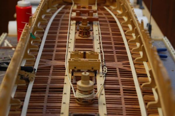
Thanks Guys. Aliluke I see if I can answer your question. I went through vol 4 of David's book Rigging a sixth rate Sloop and he doesn't mention messenger cable, only the anchor cable, which had a circumf of 13 inches and a diameter of 4inches. Also went through some of the other books such as Eighteenth century rigs by Marquardt , Lee and Steel and none of them seems to give any information on a sloop of 16 guns carrying a messenger. Now could she have carried one maybe, but I don't think so. According to Lavery, Arming and Fitting, page 47, in 1790,only sloops of 200 tons or less and smaller vessels, had no messenger or Viol. The Viol went out of style several years early. To me since they don't have any thing mention in the Steel list, they might of used one of the other smaller spare cables as a messenger using it in the same way that Brian Lavery show's on page 49, but just didn't call it a messenger. As far as the roller David doesn't mention one, so I would have to go with him on that one and he doesn't show it when he was fitting out the manger with the other items. They do have a lower capstan Aliluke on the lower deck and the upper and lower one was connected together. The crew would turn the upper one which would turn the lower one which has the cable going around it, which hailed up the anchor cable. They did use the upper one sometimes when they were hailing up the yards, upper mast and other heavy work, on the upper deck. Has far as the joint, mine may look a little bulke but I don't think it caused them to much of a problem, and hopfully once I finally get this detail done it should be more of a resonable size. From researching this it shows a sailor with what looks like a pry bar, to help keep the cable from riding up on the capstain keeping things from binding and getting tangled up.There is a very good picture of this also in Lavery's book on page 49. As far as the cannons and frapping the tackle ropes, I do believe that they could of been fraped when ran out, but don't hold me to that. Am still debating on this item but hopfully when I finally get them installed, they should be some what right. I guess I just like the look of them being fraped verse's just coiled on the deck. Hope I answer all of your question Alistair and you can ask all the question you want and will be more then happy to answer them. Gary
-
Thanks Mark and Wacko. I have come across pictures of them in books such as The Irene and Brain Lavery's, The Arming and fitting but no scale to figure out the sizes. Bourdroit gives a couple of plates in his 74 gun book, plate XXXIX and plate XL. The first plate doesn't give a size and the second plate says 1/12 scale which should be a big help. I have gone through severely of the Bourdroit books to see if they have this detail on any of their plans, but so far nothing. Always thought that each gun had all the same tools but they don't. If you guys come across the invertory of ships around 1780 could be some help. Another book that I have by Nicholas Blake, Steering to Glory, A Day in the life of a ship of the line, has what I would call plates and the fourth plate show's the layout of the gun crew. It does show the rammer and the sponge as one tool and the worm and maybe the ladle as another tool. It also show's the match tub,salt box's and a few other items. Funny how much one needs to know about them, such as how big was the match tub. It does appear that 3 matches are sticking out of the top of it, makes you think that maybe two or three cannon's worked out of one. Well Back to work. Gary
-
Thanks every one.Your like's and comments mean a lot to me. Well guy's back to work. Gary
-
Hi everyone and Merry Christmas. Have a question about the gun equipment or more on the size of it. I have looked through books, such as Goodwin,Lavery and a few other's and so far have not come up with the dimension of the items such as the crow bar, sponge, and the other items that the gun crew's needed to load and move the gun's around. I know that some of the items such as the thickness of the sponge probably depended on the hole of the barrel but what about the length of it and the handle and it's size. One would think this was easy information to find but so far its sort of hidden from me. Thanks in advance and Happy New Year. Gary
-
Merry Christmas Chuck, Michael and to the good folks for the likes. As far as letting the maple oxidize Michael I will sir. Gary.
-
Thanks Guy's. I do still have just a tad of planking that I want to do at the hatches. Other then that maybe a clear finish over top of it, to bring out the detail of the pegs and seams. Gary
-
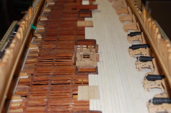
Merry Christmas and a happy new year every one. Thanks to every one with their kind words. It seems that I have a small up date on Montagu gun deck. I took off the planking I installed the first time, or was it the second time but instead of installing just enough for the gun's, ran it all the way over to the hatch ways and left one side unplanked. The deck planking is silver maple and boy is it white and every thing has been pegged but have not done any kind of stain on it. Thinking about toning it down but not sure of the how or with what so if you have any ideal's please let me know. Have been expermenting but not happy with what am coming up with yet. Do know that Frolick used maplewood on his deck of his La Belle Poule, and looks real nice. Seems it is a honey oak color and doesn't blind you when you look at it, but havn't found out what type of maple and if you know what type maple and stain please let me know. The cannons are just sitting on the deck till other items get done and will be reloacted to a safer place once I start working on them again. Any way folks Merry Christmas and may you get that tool or kit that you been wanting for the past year. Gary

- 835 replies
-
- 19
-
-
How do I make a "made mast"?
garyshipwright replied to md1400cs's topic in Masting, rigging and sails
Hi Michael. Frolick shows how to make a mast in his book, The Art of Ship Modeling, on page 185. Its a very good book and does give one some insight's in to other items like casting cannons, framing and a whole lot more. Good book for your library. Gary -
Solder brass rod for deadeye
garyshipwright replied to cog's topic in Metal Work, Soldering and Metal Fittings
Hi Garward. Nice work sir and was wondering how do you make the round dome heads on the bolts? Do you have a jig and is it possible for you to show how you make other metal fiitings also for your works? Am very interested in how the good folks of the site make different item's in metal and yours are high on my list. Thank you sir. Gary -
Hi Rusty. Nice build sir and seems that other's have allready taken the good word's so I am taking my hat off to you sir. Good job. Gary
- 421 replies
-
- 1
-
-
- granado
- bomb ketch
- (and 2 more)
-
Hi Nigel. I downloaded the accessories PDF sir and the only item that I saw was bolt's with nuts and not clenched bolts. Is that the item? Thanks Gary
-
Thanks Nigel. I went to there site sir and nothing comes up or at leasty what I can see. Any more help would be grateful, knowing what sizes and cost of them also. Thank you again. Gary
-
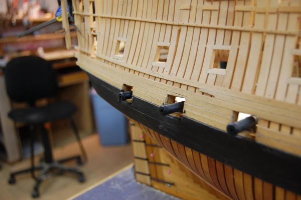
Hi Alex. Have a question for you sir and wondering were you found the information. The clench bolts that you show on the outside of the gun ports, was this done on English ships? I thought that this was done on French ships but was hidden on English ships under the outer planks. Another question is how is this detail done, cast or metal work and can you show how this was made. Thank you sir. Gary
-
Your very welcome sir. As you said there was a lot of variations on the theme. Just wish I could find more of the top and butt showing on the gun deck and would have done Alfred's gun deck like that. One thing is for sure , when ever I get to the upper deck, her planks will be done in the top and butt. On the Montague, they are already in my stash of plans sir. Was going to copy my wale planking according to her's but went with, hum come to think of it, can't remember who. Gary
-
Hi druxey. I would normally agree with you sir but I found two plans that show the planking laid out at the NMM, of the Tremendous of 1784. Her gun deck shows straight planks drawn in,J3001 and her upper deck J3002 which does in fact show the outside planking in short lengths, cut in top and butt. Also there is that one of the unknown 74 which shows the upper deck with straight planks instead of top and butt planks. One thing that I have thought about Steel Plates of her gun/upper deck. Her gun deck shows the binding strakes and the upper deck show the lay out of the planking along with the top and butt plank's. Guess my question is why didn't he show the lay of the planking on the gun deck like he did for the upper deck. We may never know sir. The other plans are the Venerable of 1784, J3049 and J3052 which also shows the lay out of the planks and her upper deck only show straight planks along with the Cressy of 1807 of her upper deck which show's straight planks. From what I can tell druxey, only the plan of the upper deck of the Tremendous, shows the top and butt planking. May be you eyes can make out more of the detal sir. Do you have any primary plan number's showing the lay out of the planking for the gun/upper deck of any of them. Would be happy to have a look at them if that's ok with you. Gary
-
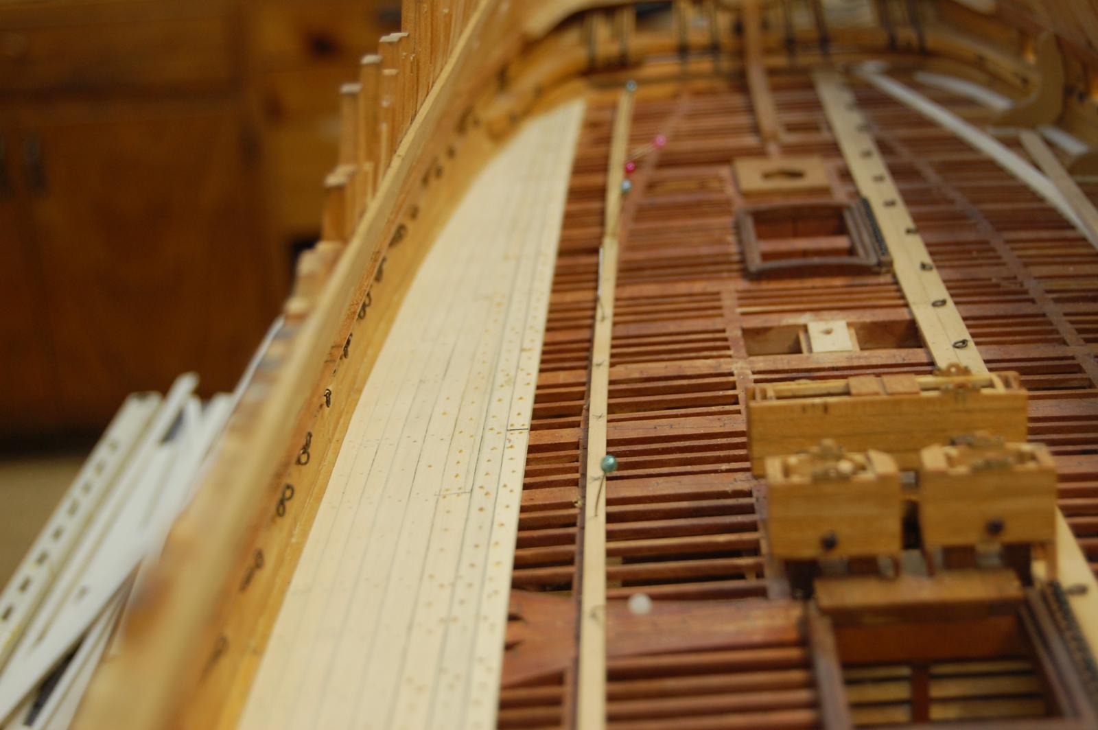
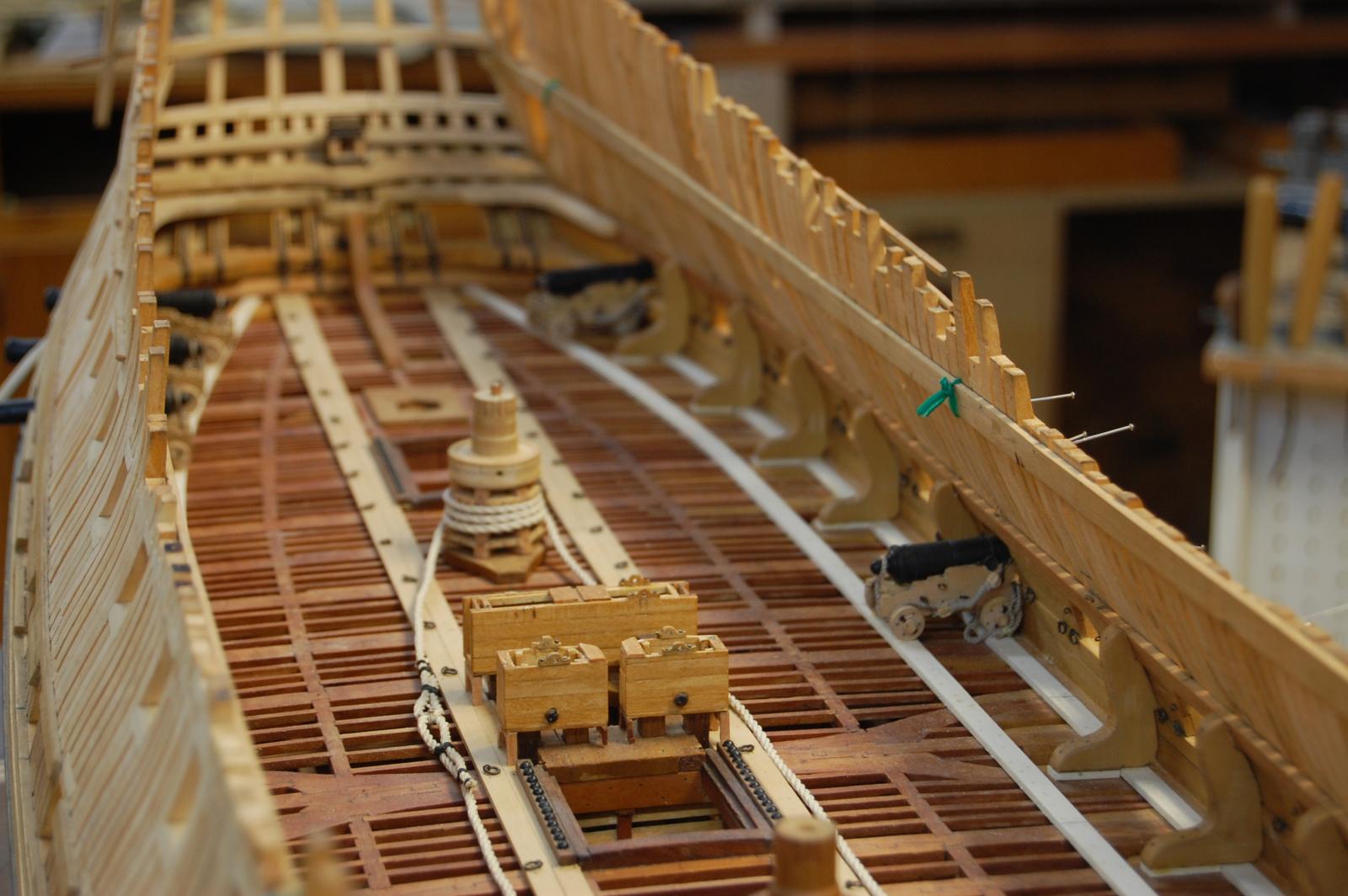
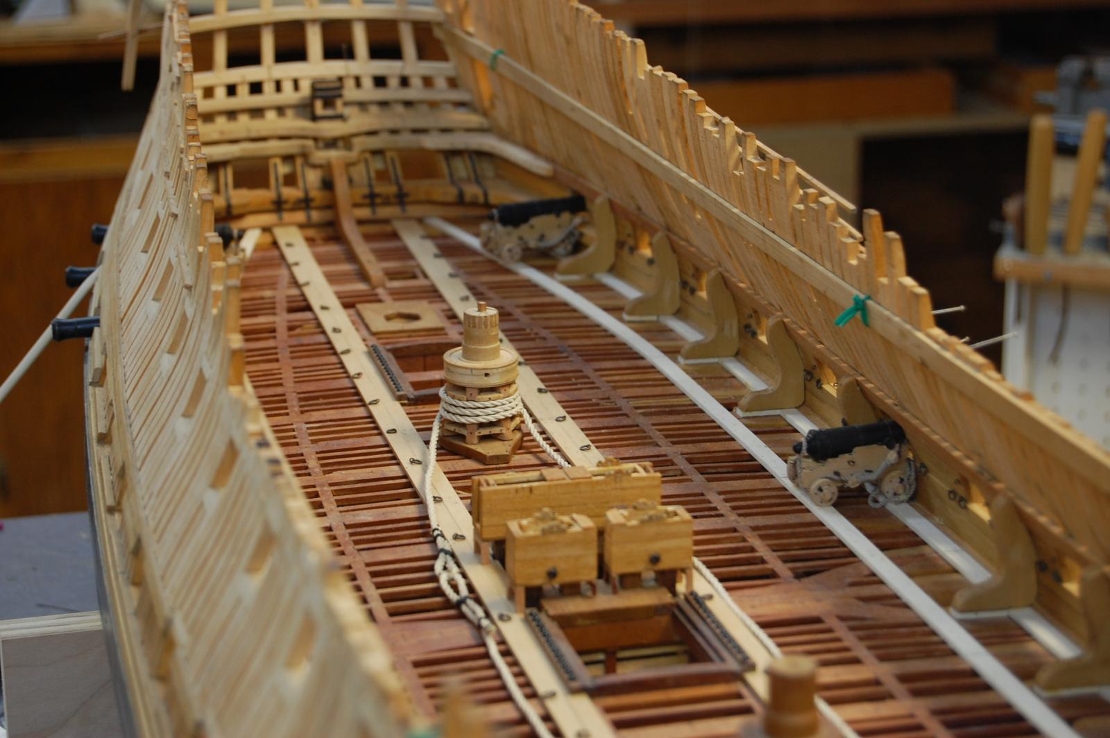
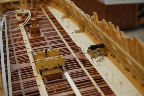
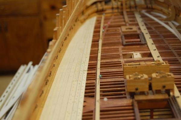
Hi Daniel. I have to agree with druxey sir and from researching the deck planking for Alfred it does look that planking was straight parallel planks after 18th. From researching this, to be some what accurate on Alfred, there just doesn't seem to be to many plan's showing how the planks were laid before 18th. at least what I can find . The ones I have found show curved planking before 1800, which has been reduced in width as it progress aft and fwd. Another thing I have found is that on the gun deck the outside plank's was joggled in to each other and the upper deck out side planking was worked top and butt, which seems to be different then what Peter Goodwing say's in his book. It does seem that this was not always done, looking at other plan's. They only give rules for the out side planking and the binding strakes which were to be oak along with the first shift which was also to be oak. It does seem that laying the deck is a lot like running the plank on the out side, a jig saw but a fun type jig saw. To me, laying the deck in different width's and in a curve looks more pleasing to the eye's. More in keeping with hand cut plank's, done in saw pits. Here is a photo of Alfred's deck laid so far. If you want to see some plan's showing the lay of the planking, go to the NMM site and look up Tremendous 1784, and J7921 unknown 74. Once you start getting in to the 1810 ,1815 time frame planking seems to have been layed much different. Gary
-
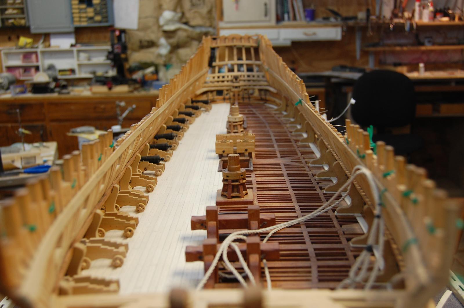
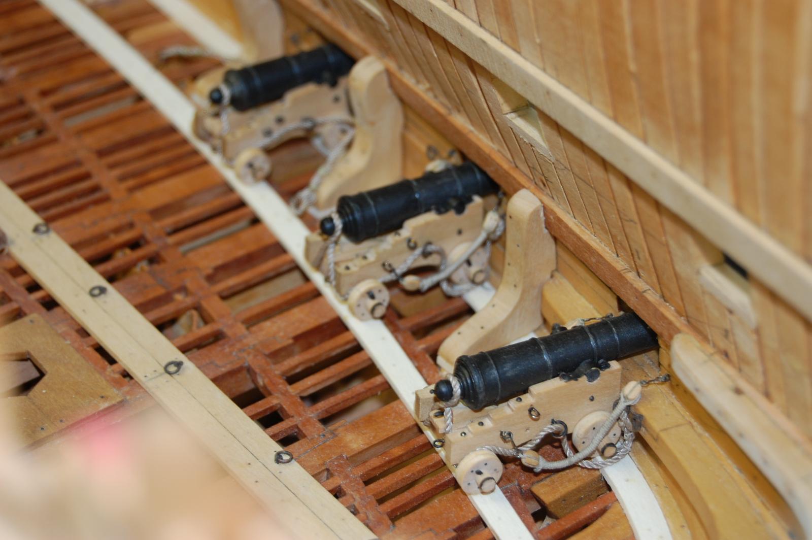
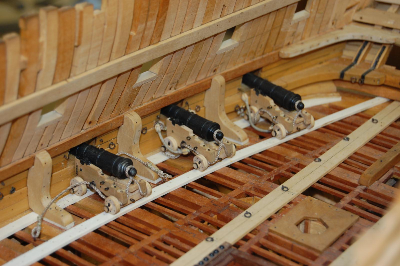
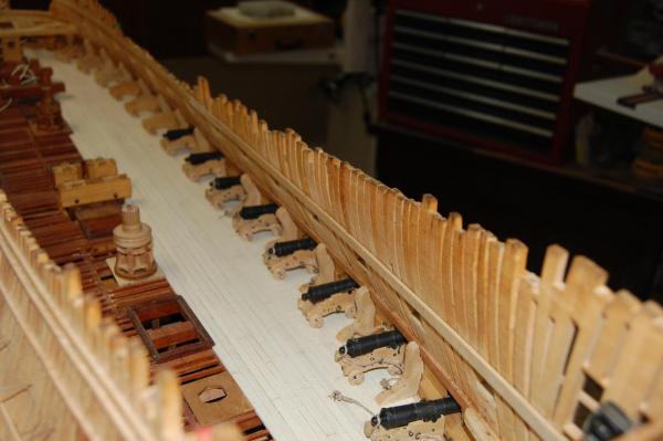
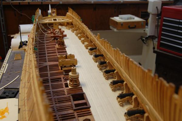
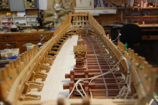
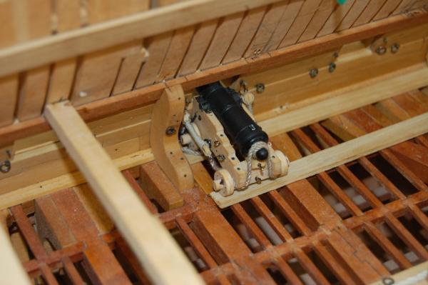
Hi Remco. Thank you very much sir. Am glad you like the cannons sir and seems that your statement is just a little modest but I do thank you. Here are some more photo's of the gun deck with a few more details. Am not sure if I will leave the curve planking which is due to the curve of were the back of the cannon truck's land. May just plank one side for cannon's and leave the other side alone. Reason is that I just don't want to cover all of the detail up and am sort of stuck on the do I want to or not decision. :mellow: Gary


- 835 replies
-
- 15
-