garyshipwright
-
Posts
937 -
Joined
-
Last visited
Content Type
Profiles
Forums
Gallery
Events
Everything posted by garyshipwright
-
 Hi Larry. No hurry and my wife says that I move like a snail. As far as the issues with the water draining off of the cables, the deck boards were not made water tight being that the orlop deck was below the water line, and guess they figure it would not do any good, make getting at the supplies harder. The cable tier beams in that picture seem to be a little on the large size and would of looked more like the ones on page 114. You probably already know this part but they were just used to provide a space for air movement underneith the cable's to help them dry and prevent rot. The reseach I done on that part Larry said that the battens were 2 inches thick and was placed every 2 foot in the cable tier. Being that I didn't put any planks in the area only left me the top of the beams to put them. Let me know good sir if there is any more info or help on her. Gary
 -
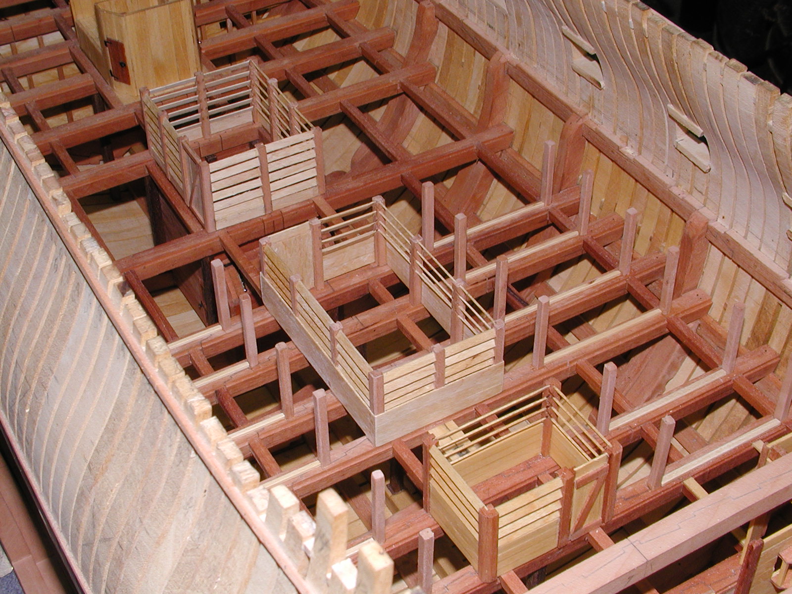
Hi Ed. Not sure what to say other then a heck of a job. On a side note and would like to see him but could you put your figure next to the hull like in photo 7 above. Just want to see how it looks with him standing beside all of that framing which Is what I like best about building them. Thank you sir. Gary
- 3,618 replies
-
- 1
-

-
- young america
- clipper
- (and 1 more)
-
Good to see you back Mark. Wil be keeping a eye on this part and am sure to learn some thing to help on Alfred Stern. Does seem that this is one of the hardest parts other then the rail at the stem. Keep up the good work sir. Gary
-
Thanks Tim. It was a fun project. I got some more metal from Micro Mart for making some more pot's and pan's, but havn't got around to doing them yet. Been working on the capstan and a good shop clean up. Funny how not finding a tool because of the other stuff on top of it will make let you know that its time to clean up the shop. Gary
-
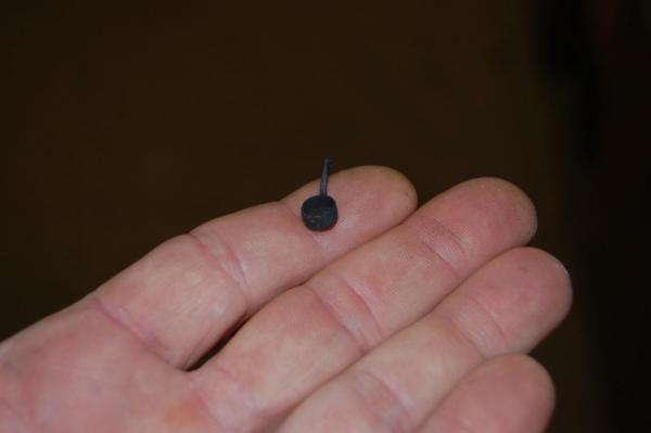
Thanks Mark. It does make one stop and think till you been on a air craft carrier which had a crew of 7000. Try feeding that many guys. That is untill you find out that they had three kitchens that usually work 24/7. Had to work in one for two weeks when I was on board the Midway. Lots of fun for sure. Hi Larry.Thank you sir and am glad that my log is a help to you. I was going to ask Larry but have you started a build log and would love to see your Alfred on here. Now if I understand your question your asking about the grating/deck planking on the orlop deck around the pump well? As far as grating on this deck am not sure that other then in the middle were hatches would of been may of been the only place for grating, which probably been flushed with the planking. Most of the plank's would of been short and fitted in to rabbets on the forward and aft edges of the top of the beams, which could be removed in order to get at the supplies in the hold. If I was going to plank it I would have just cut short planks to fit between the beams. They did also fit carlings and ledges between the orlop beams to help strengthen the short planks between the beams but I didn't install them also. You may of miss this detail on the orlop deck so have included a photo showing the rabbet. Peter Goodwin in his book Sailing Man of War, show's on page 59 fig 2/8 how the planks would of looked accept I do believe they would have been flush with the beams. Keeps one from stubbing a toe that's for sure. Hope this is of some help Larry. If it doesn't answer you question let me know and we will come up with the right answer. Gary

- 835 replies
-
- 18
-
-
Hi Rob. She looks very very good sir and is really showing her curves, just like a beautiful women. Your wood working is very good and have been watching your build and looking forward to seeing more of her come to life. Good job sir. Gary
-
Hi Mark. Just to let you know sir, the French did have sister frames like Hahn did, only they were thicker sister frames. Your right they didn't have cant frames but one and this would have been all the way back at the stern, which I do believe was the fashion frame that connected the stern framing with the last square frame at the aft part of the ship. As far as the spacing have to agree with you, this also was different then what Hahn did and at the moment am unsure of what that is but will take a look in the Boudroit books and let you know. If you need any kind of information on the French ship sir, please let me know. I have quite a few of the Boudriot books and will be more then happy to pass along any info that you may need to help you. I have the L'Amarante of 1741, the La Renommee of 1744, the Salamandre of 1752 and the Boullongne of 1759 which should help you build her in her time frame. Look forward to your new build sir. Gary
-
Hi Alex. Its a outstanding carving and am sure I will never be able to do one with just detail and beauti but isn't his left arm post to be at chest level and his right arm at waist level? Outstanding carving sir thats for sure, and thank you for sharing. Gary
-
Hi Guys. Have been using one for a few years but have the number 7 lens the longest. I went and brought the number 4 from, micro mart I believe and after trying it went back to the number 7 which seems to work best, for me. Don't believe that micro mart or model expo sells the number 7 but if your interested in getting this one go to http://www.contenti.com/index.html You also just may find other thing's you just may want to add to your ship building tool's. One thing I have learned over the years and am sure many of you have known this, but jewelry places sells some of the best and accurate tools for ship builder's. Gary
-
Well folks, seems I have found a bit more information on the drop pawl's and weather or not fitting them to Alfred capstan's would fit her time frame. In John Harland's book, Capstans and Windlasses, gives this on drop pawl's. Drop Pawls were fitted to the base of the capstan and appear at the end of the 18th century. These were a big imporovement over the sliding pawl since they could be left in the engaged position while heaving in. By fitting the pawl rack with twelve teeth, the range over which there was danger of back slip was halved and indeed if the pawls were out of phase with each , or there were more teeth , the danger of back slip could be further reduced. Another book which am sure many of you have, Peter Goodwin, The Sailing Man of War, also shows drop pawl's on a capstan in 1735, on page 146 and on another one in 1780, page 149, which so happens to be a 74 gun ship. Kind of funny, not sure how many times I have looked at the pictures and never noticed the drop pawls . Gary
-
It could turn you in to a scratch builder. Well another one you could go out in your back yard, make that your neighbor's back yard cut down their pear tree or apple tree and make some fine planking out of it using the Byrnes table saw, of course you would also need a band saw or a larger table saw, but see you can buy a few new toy's. Or just get some wood from the lumber yard and cut it down. All kinds of good reason to buy a Byrnes saw. Gary
-
Thanks guys. Am sure that others will also find this to be helpful in their quest for tools that will be a good addition to their shop. QA that is one hell of a machine, pardon the pun sir. You can really hog off some wood with that.You modification to you belt sander are out standing that's for sure. I did go out in the work shop and tried my belt sander and seems that it did a good job on one of my HSS lathe tool which looks like a V and then also shapen one of my small wood tuning tools. It worked and may just save me a couple of dollars in the future. If not I probably go out and order the bench grinder your showing QA. I have always like Grizzly tools and are a good price for what you get from them. My jointer and table saw came from them and are a real joy to use. Gary
-
Hi every one. I went through the tool log's and seems that there isn't much writtern about the bench grinder, at least none that I can find here on the site. We as a crew cover a lot about the different tool's and this is great for folks who are starting out and even a few of us that are tool junkies. I really do love reading this part on MSW about new items that may pass me by because I didn't know or didn't see it in a build log some place. Any way am thinking about getting a bench grinder and the main reason is to shape my lathe tool's in to different shapes for making parts and pieces.After that am sure I find other uses for it if I get one. I have a belt sander and even a Tormex sharpner but really wondering if I need a bench grinder. I really don't want to use my tomex for grinding and figure well maybe the belt sander could do it. Have not tried it but may give it a shot. I know that grinders are not expense but do you have any thoughts about one and how would you shape your lathe tools with out one? Any thought's guys. Thank in advance. Gary
-
Hi Rusty. It looks good sir but can you show a couple of different view's of it? Looks to be the right size. Gary
-
Good job Remco. Think I box up my pots and pan's and come over to your place. So what's on the menu? Gary
-
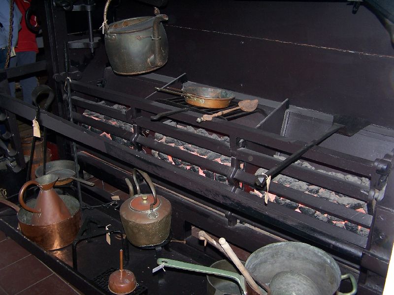
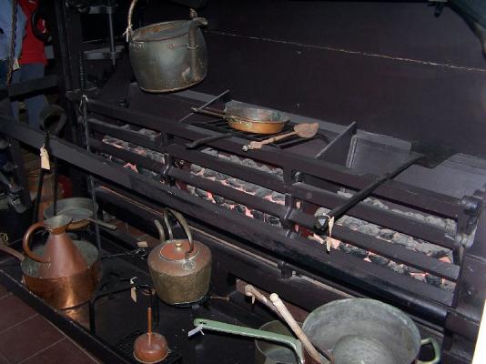
Hi druxey. Sorry sir I don't cook, accept maybe a can of soup Hello Marsares. Don't believe I will sir. That may just be a little to small for me but it's a ideal I just may have to look in to. Hi Sailor 1234567890, and thank you. As far as I can tell from looking of this photo, at the equipment around the Victory stove I would say yes they did. It seems they even had frying pans which I just may have to make a couple. As far as the giant stock pot there was two big boiler's on the other side from the grill section plus a stove for cooking bread. Gary
-
Thanks Ron. But can we have a recount. I vote for Remco Hi Remco. Lovely job sir on those items and thank you. They do seem to add life to the stoves don't they. I do remember reading some were that the beauty is in the detail's and must say, you hit the nail on the head. I do have a couple of more items to add and do agree, sure don't want to turn it in to a doll house. Hi Pat and thank you. Well maybe a little and but do believe Mr Jones just may put up a fight if I put a dress on him.
-
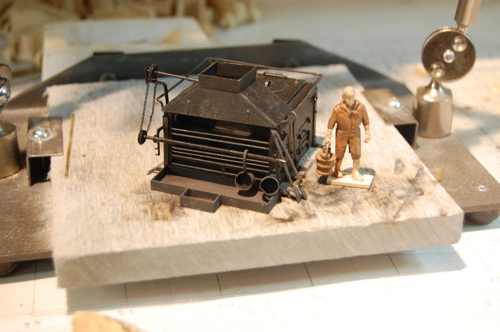
Hi everyone, I went and made a few items to go with the stove but after looking in on Remco stove and pot's, find his to be a lot cuter so going to have to do a little face lift on mine to make them just a tad cuter, if that's possible Beside got to thinking, whats a stove with out pot's and pan's. Remco see what you went and made me do. Gary

- 835 replies
-
- 12
-
-
Well Remco. Guess you win sir. I made a couple of small pans but I think your's are more cute. Good job sir and as druxey said the only thing missing is the soot stain's. Gary
-
Hi Mark. The cross section is also on page 27 of the AOTS Bellona, right below the one of the Ajax. If you look closely you can see the drop pawls on the lower capstain. Gary
-
Good job Remco. Now I know were I can get at least one pot from. Gary
-
Thanks Mark. Thats what am trying to figure out is the drop pawl's and if maybe they would of fitted Alfred with them in 1780. As I posted earlier, they were being tested in 1770/71 but not much is said till 1787 or so time frame. Guess I could always say that maybe Alfred got them a little earlier. Hum guess I may just have to sleep on that one. Mark you said the Ajax? Can you tell me were you found the name to go with that midsection? Have been looking for it's name, but have come up short. I do know that Alex said it was from around 1790/ 1800 time frame. Gary
-
Thanks every one it was a real joy to build. At the moment am working on the cooking equipment, that is as soon as I get enough research on them
-
Nice Going Remco. I knew you could do it sir and nice looking brick fire heath by the way. As far as different kitchen utensils, I seem to be in the market for some my self. If you find out the sizes of the different items let me know, would you please. Good job. Gary