garyshipwright
-
Posts
937 -
Joined
-
Last visited
Content Type
Profiles
Forums
Gallery
Events
Everything posted by garyshipwright
-
 Thanks Antony and Alex. Gary
 -
Thanks Wayne. Will take a good look at it sir. Gary
-
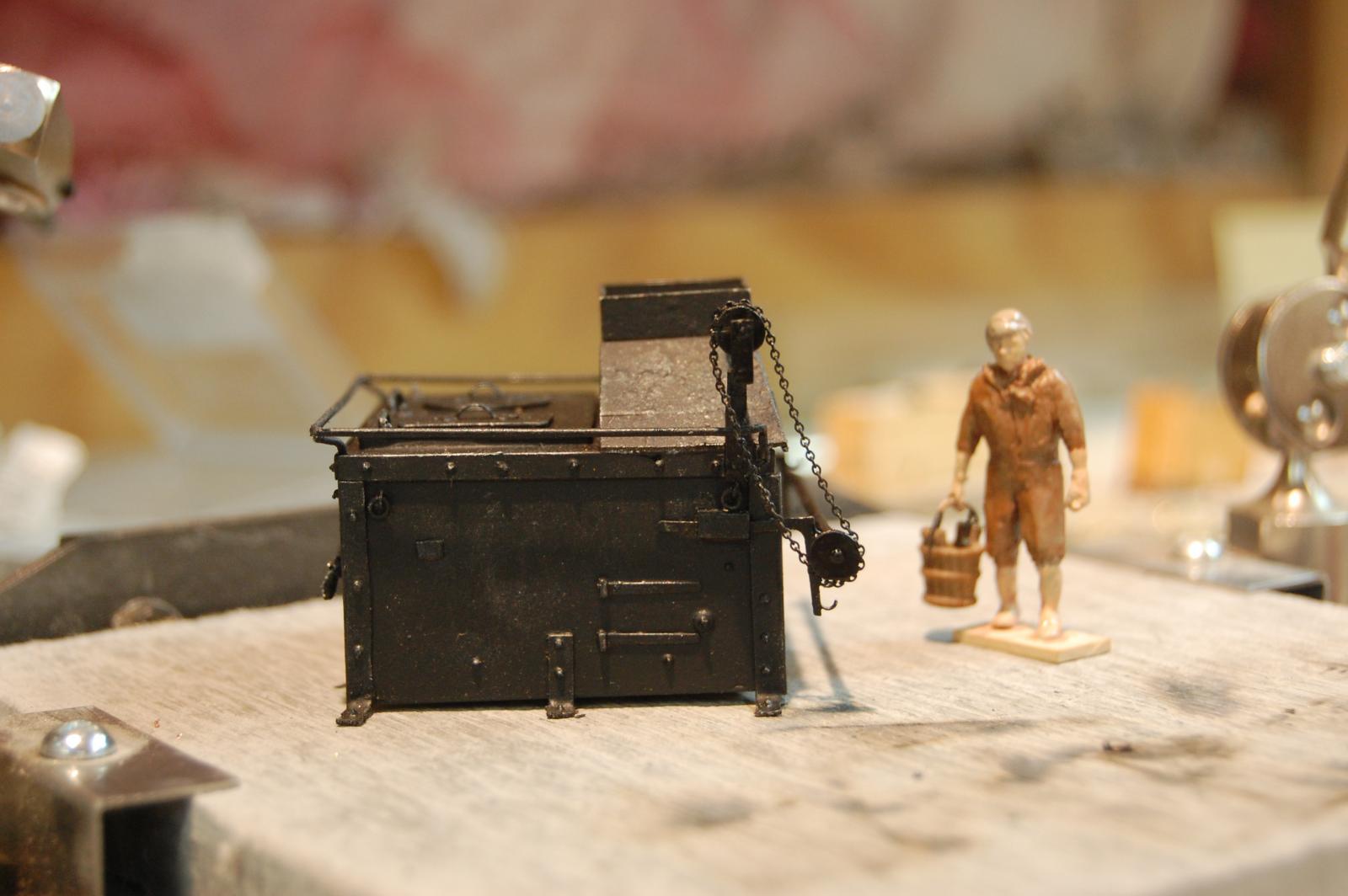
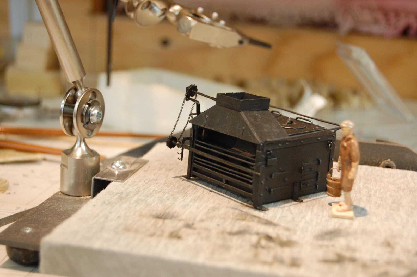
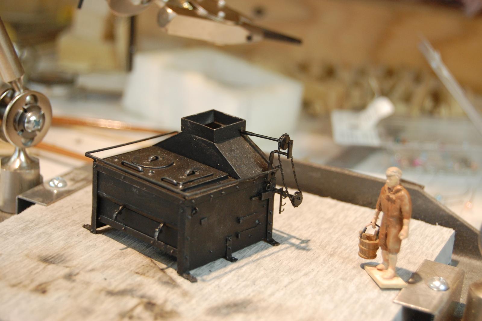
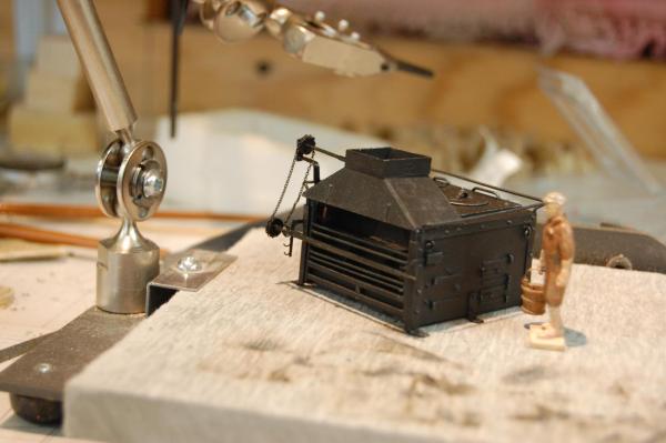
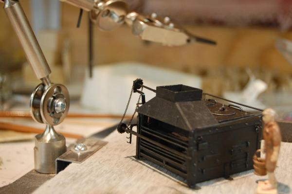
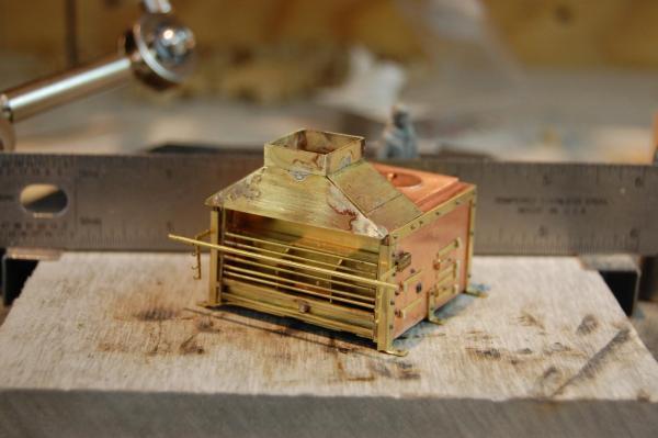
Thanks Michael, Pat and Alex. Well good sirs other then pot's and pan's the stove it complete, accept for the stack. I finally added the pully's and chain, for the pit, which was just a little touche. Most of the new parts are made out of metal accept for the pulley's which are wood. Couldn't find any brass round stock big enough. Well back to the pump's. Gary


- 835 replies
-
- 20
-

-
Hi Michael. I have been going through your log for the last couple of days sir and must say that your metal and wood working are outstanding and top notch. It does seem that you have a very good relationship not only with wood but with metal which am still working my way through it. Will be keeping a eye on you log sir and have already learned a thing of two that should come in handy for Alfred. Have enjoyed your log very very much, and look forward to more updates. Gary
-
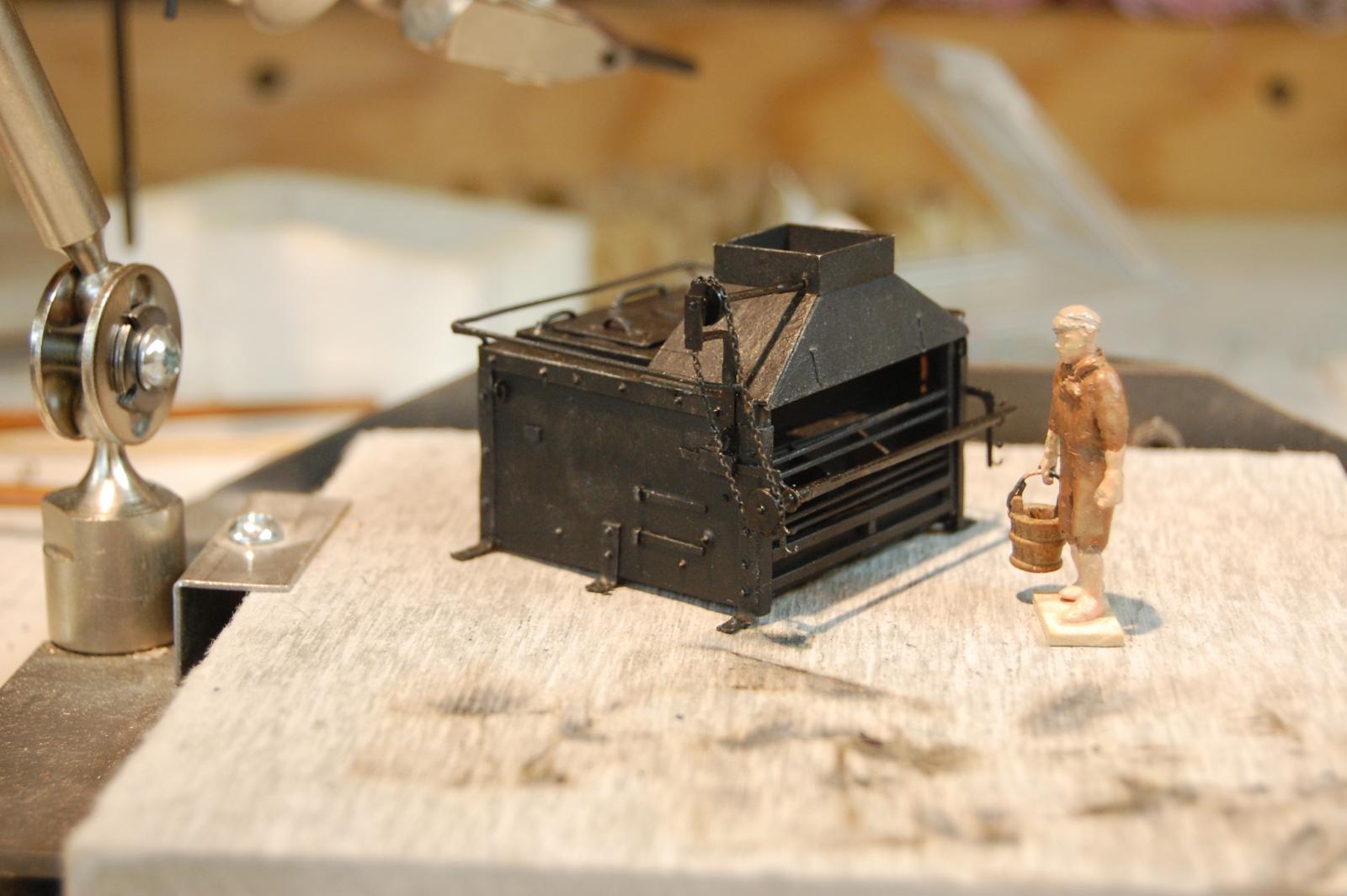
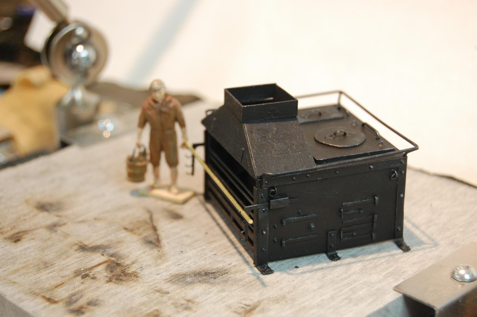
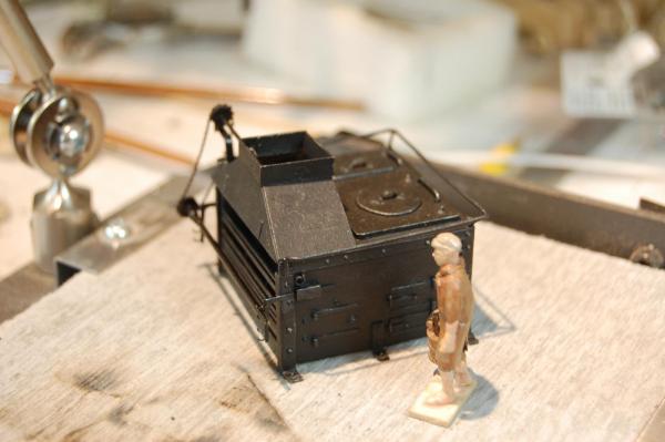
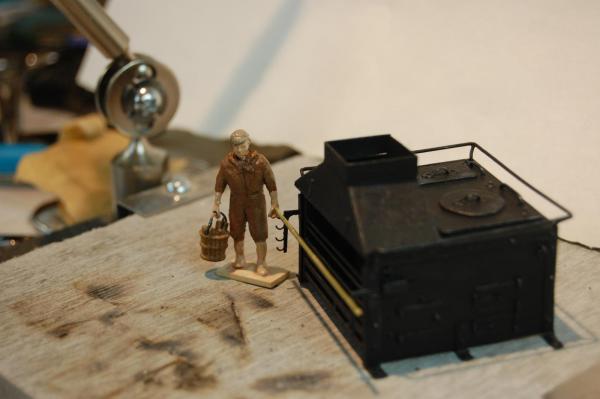
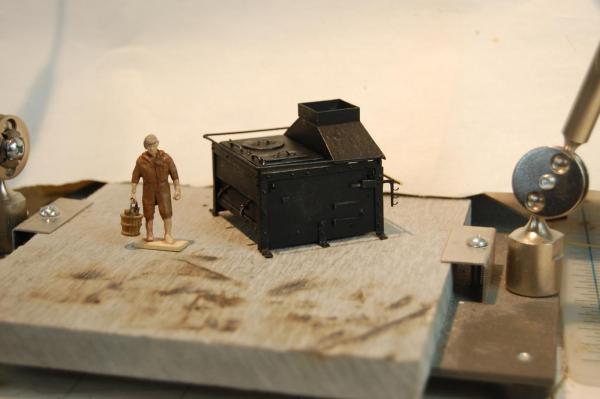
Hi Mark and thank you sir. I had some metal priming paint that I sprayed it with and then sprinkled it with baby powder, not to much and most was blown off before the final coat of flat black was put on. I do believe that David in vol 2, TFFM, talked about putting some on the mould before he poured the metal for cannon's, to give them a cast look, so figure why not. I did do a little dry brushing with a couple of different paint colors on top of that to help high light certain area's. My wife thinks its a cute little stove, which is okay with me, being that she is my biggest critic. Thanks druxey. Gary
-
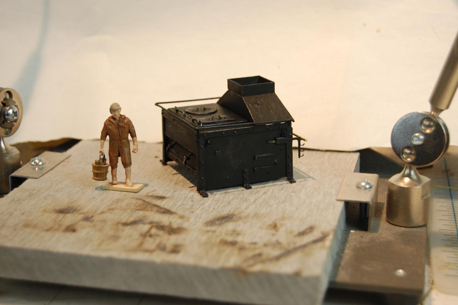
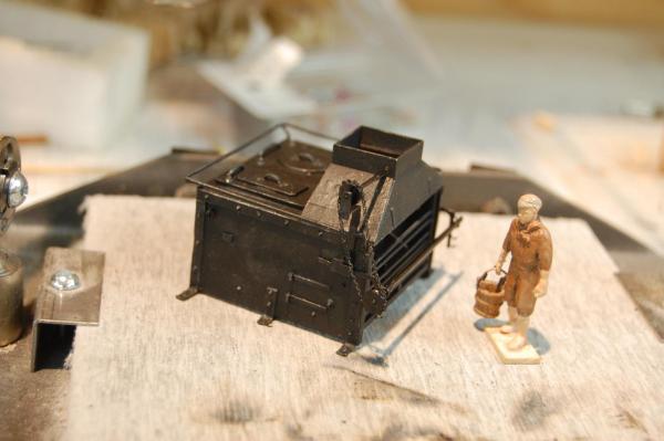
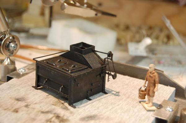
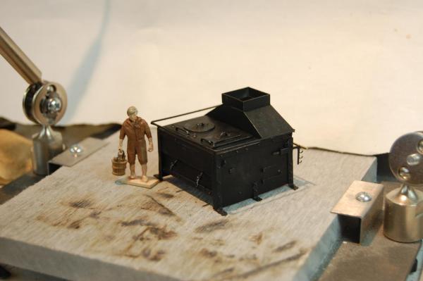
Thanks every one and those folks for there likes. I have got the stove further along and do think I have come close to the cast iron look, at least as close as my skill will let me. Well back to work on her gun deck guys. Here is some updated photo's guys, and Mr Jones finally got a paint job along with the stove. Some were he seem to have picked up a slop bucket. Now I wonder where he got that from. Thanks again guy's. Gary

- 835 replies
-
- 25
-
-
Thanks Ed and druxey. It has come a long way from just a picture in a book and thanks to you guys for the gentle push to do even better. Of course build's like yours help to set the bar. As far as the scale pig, I just may go to the railroaders to find one and maybe a chicken and cow. Gary
-
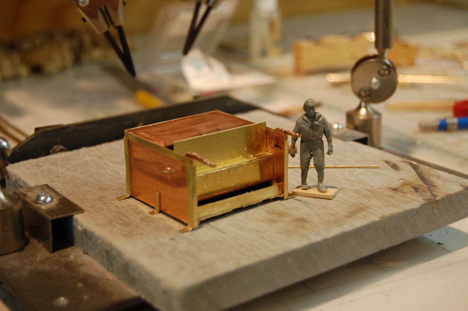
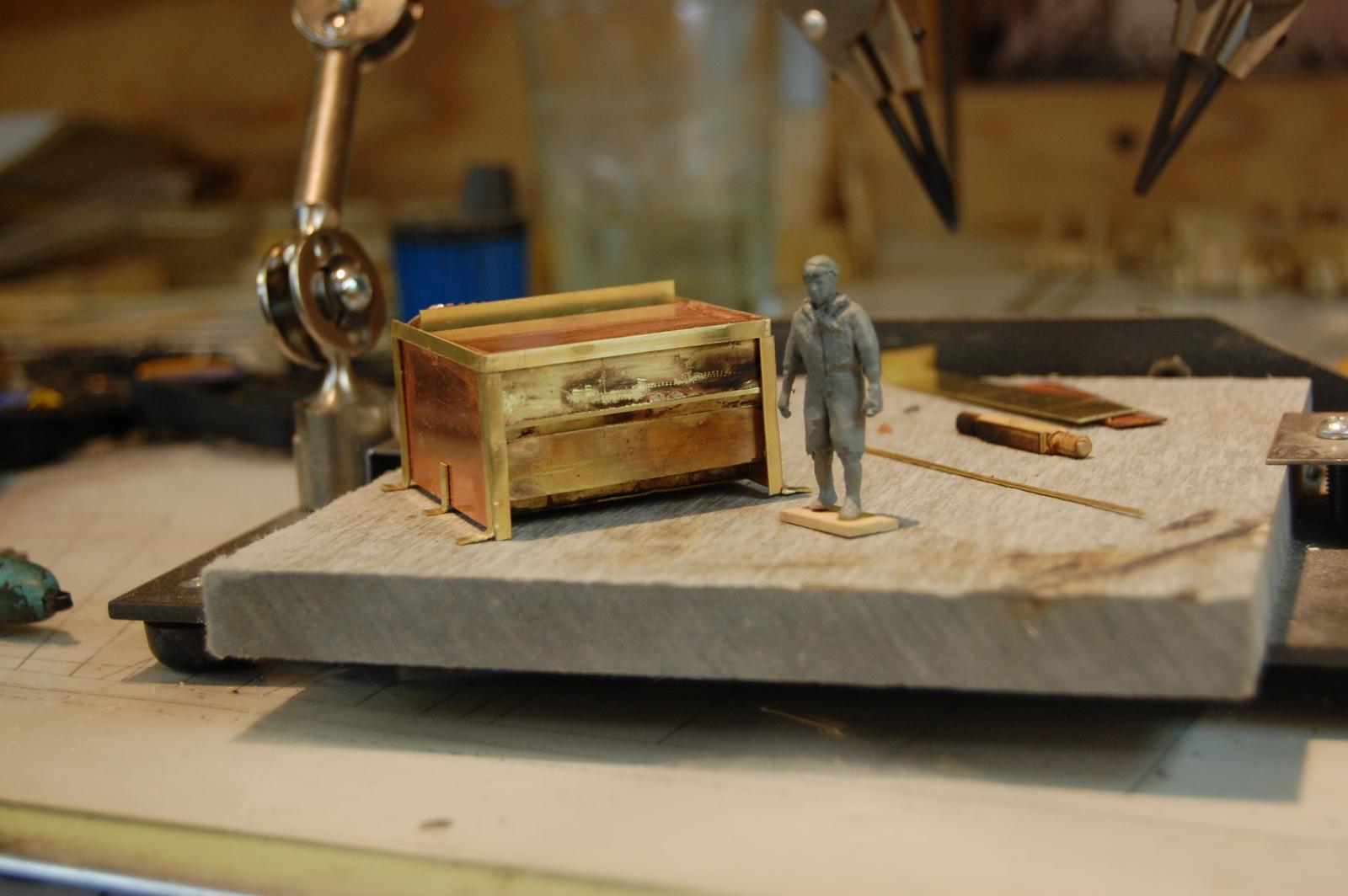
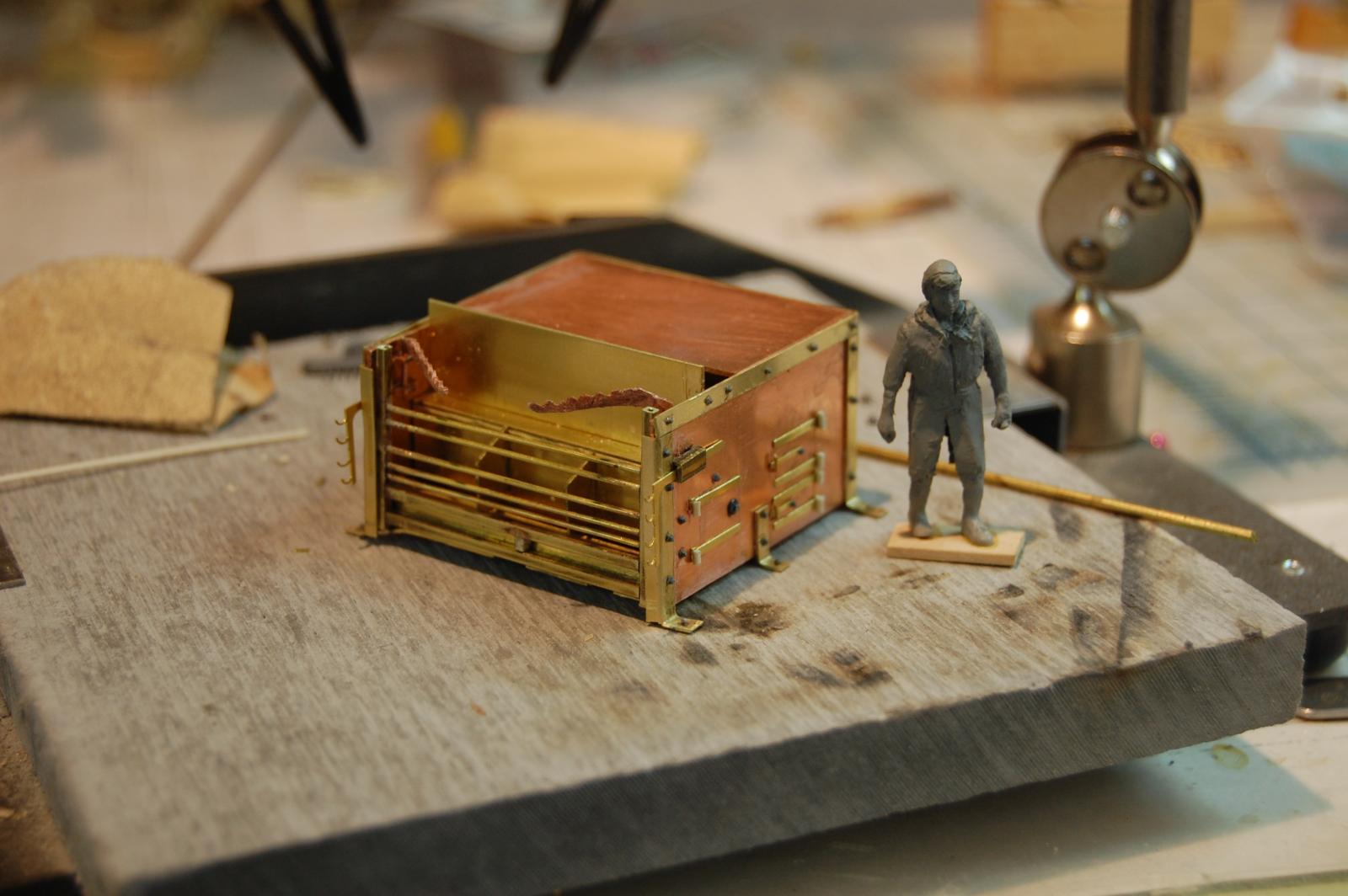
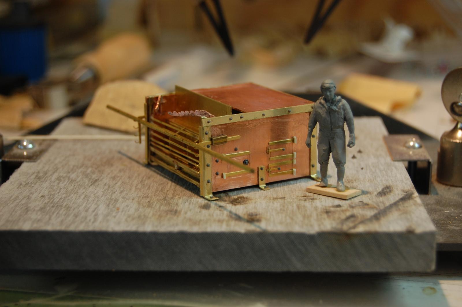
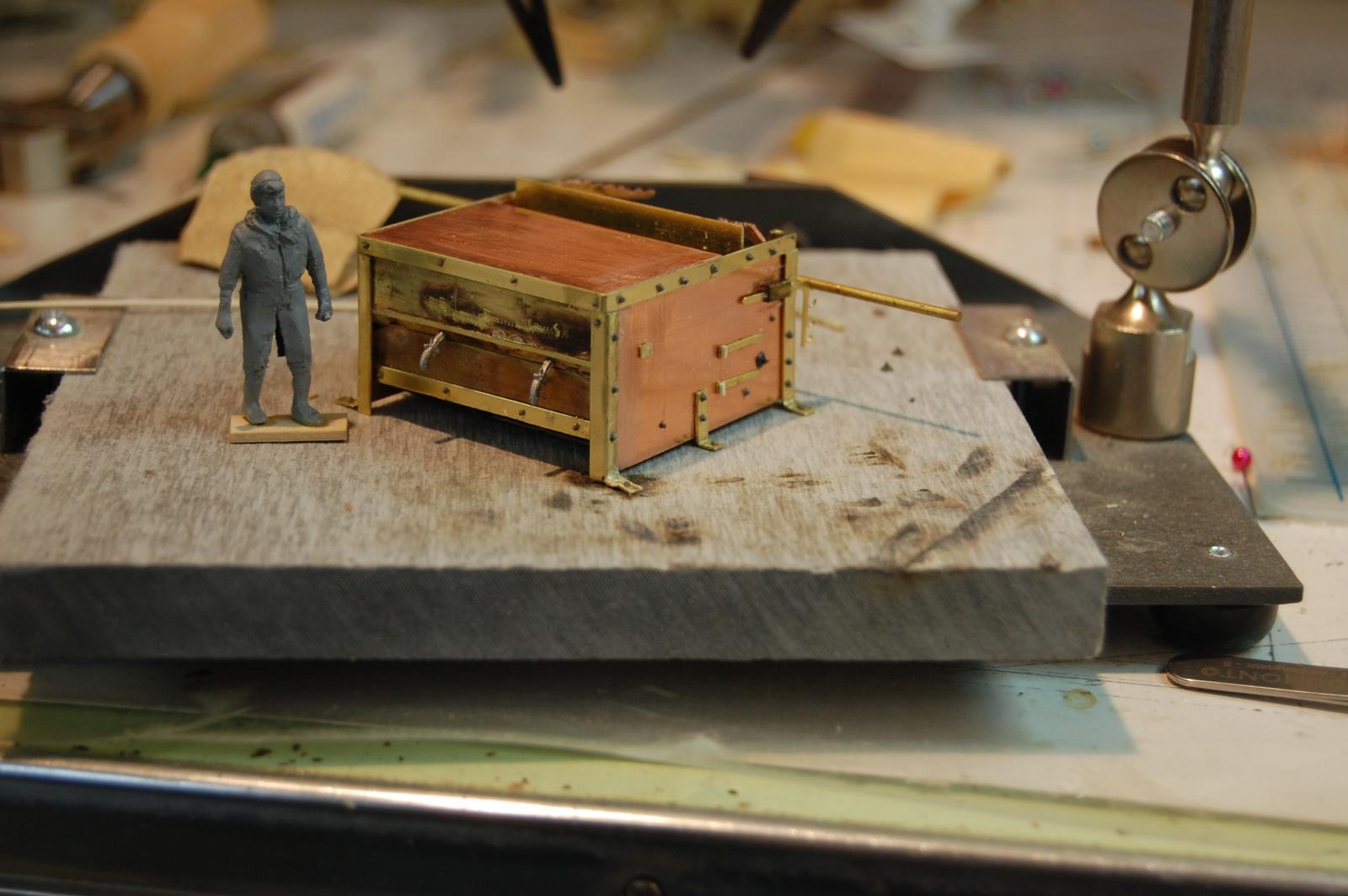
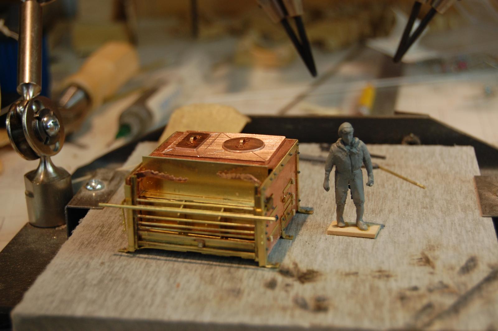
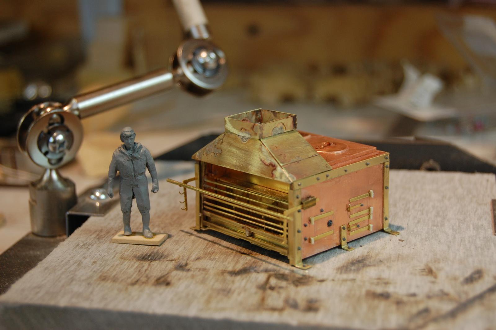
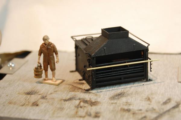
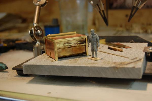
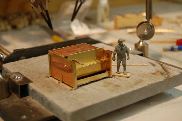
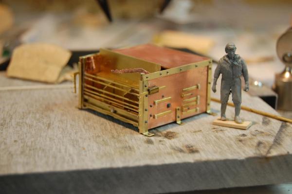
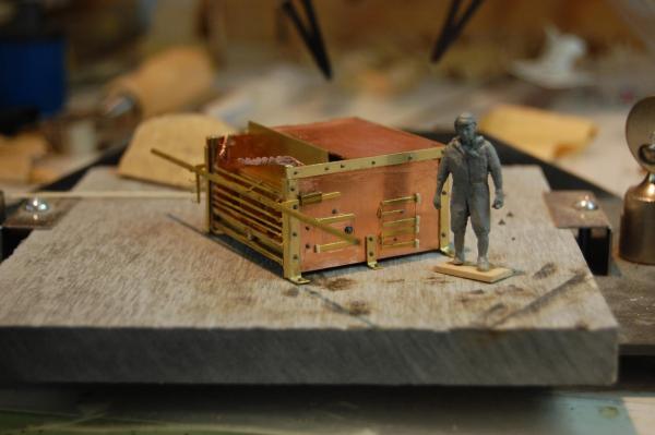
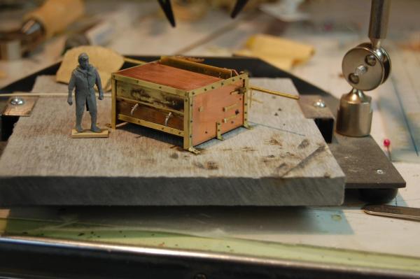
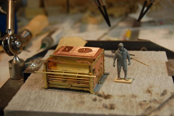
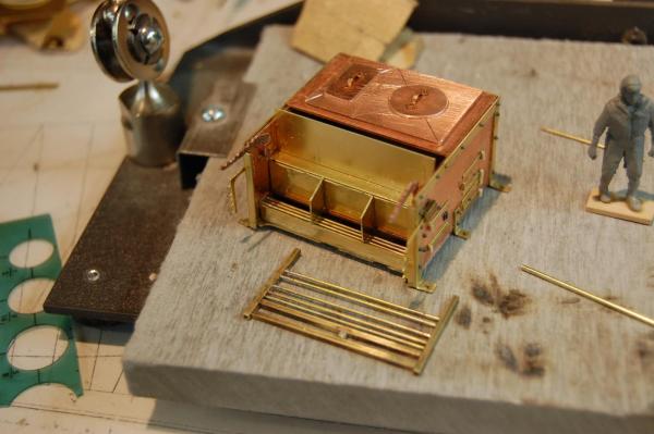
Well guys, I got to finally do some cooking and if any one has a pig, bring it on over and we can have a roast. Only kidding but finally have Alfred stove just about finished. Been working on it for a couple of days and has been a lot of fun. Its built of copper and brass, and a few pieces of plastic and wood thrown in to the mix. Still have to put the bar around it and finish the stack. A couple of the items, probably will get replace, such as the pot holder's and in the mean time will have to make some pot's and pans. Don't be to hard guys and still need a lot of work on it. Also have to figure out how am going to get that cast iron look so if any of you have any ideal's on how to do this, let me know, would you please. Just to let you know there was a few items that came from Chuck's photo etch set which came in real handy, so thank you Chuck. Enjoy the photo's guy's. Gary


- 835 replies
-
- 23
-
-

-
Hi Greg. Nice build sir very nice. You really do have a nice style of building that's for sure. Any way could you please PM me. I have been trying to PM you but not having much luck. Thank you sir and keep up the good work. Gary
-
Hi Michael. Thank you sir. As far as the term rhodings it appeares in Steel, Naval Architecture and in David's book Vol 2 page 95, TFFM. As far as were the term comes from, your guess is as good as mine sir. Gary
-
Hi Johann and thank you sir. I feel the same way about following your build. Your metal work as inspired me to do better with my own. Right now am working on the cast iron brodie stove and looking at what I have done at the moment doesn't look to bad. Hopfully I will have a update on it in a couple of days. Gary
-
Hi Alan and thank you very much. Gary
-
Hi Mark. Confusing isn't it. To make this simple for my self, when I made the template for the mid ship beam, all of my beams were cut to the same length as the mid ship beam in length, and all beams were given this round up using a template of the mid ship beam. This way, as the beams were fitted going aft or fwd the round up didn't change but length did bringing the round up under control. I know that when I got to my last beam, being short in length, when I looked at it doesn't seem that there is a lot of round up, but it was right. Mark you may of already thought about this but the sheer of the deck also comes in to play with the round up of the beams as they go forward or aft. Hopefully this makes sense. Gary
-
Hi Rusty. I do believe they are done as shown in you plan. The NMM plan of Grandado show's them that way. Nice build sir. Gary
-
You know druxey, have to agree with you a 100%. If any one can do a outstanding job on making one it would be Remco and it would be one of a kind that's for sure. Looking forward to it. Gary
-
Hi Remco. Sorry about that sir, seems that I stopped after I read about when the Brodie came in to the English Navy. There I went again and not looking in these other books. for infomation. For the last couple of days I have been researching Alfreds stove and how to make all the parts and pieces that go in to making one. Figure that I need some practice on my metal work, so why not make a Brodie stove for Alfred. Have been looking in HMS Victory by Bugler on help with this and after you mention Lavery's book, I find all kinds of Dimensions for the stove, so I have to thank you for pointing this out to me. Do look forward to seeing more on your build, but first I have to go get some more popcorn. Gary
- 1,215 replies
-
- 1
-
-
- sloop
- kingfisher
- (and 1 more)
-
Hi Mark. Have to agree with Greg sir, a good ideal for future use, much like Remco washer. Both good ideals for sure. I do have to admit druxey red and black color's brings her to life, and a good looking ship on top of that. Gary.
-
Hi Remco. I may have a answer for you. According to David Lyon's book The Sailing Navy List, Kingfisher was built in 1770 which and was burnt in 1778. My reason for bringing up the 1778 date is the English Navy didn't start using the Brodie stove untill 1781, when the enter into a contract to buy them. She probably had the fire heath of the old type. From looking in Goodwin's book, The Sailing Man of War, there is a fire hearth of 1770, on page 161. From looking at it, one would not need to get all the way around it. Hope this is of some help sir. Ron I do believe that the u shape is were the fire heath it self set sir, and the one grate aft of the Chimney was a steam grate as you said, I do believe. The big pot of the fire hearth probably sat right below it. Gary
- 1,215 replies
-
- 6
-
-
- sloop
- kingfisher
- (and 1 more)
-
Hello Mr Frolick. Outstanding sir and will come in handy. Am quite sure sir that a lot of modelers will find this information very very usefull such as myself. Once again thank you sir and Happy New Year. Gary
-
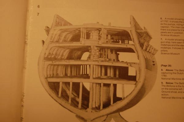
Hello every one. I was going through the AOTS of Bellona and on page 27 is a midsection of a 74 gun ship. Am looking for some information on the lower capstan in the model and was wondering what the time frame of it would be and maybe if it has a name other then midship. Am trying to figure about the drop pawl's on the lower capstan and maybe if they came in to use early then what Lavery is saying which is 1787 time frame. I do know that a new type of capstan was insalled on the Defiance in 1772, with drop pawl's, but after testing it it seems to have lost favor and nothing more on drop pawl's untill 1790 or so. The capstan was invented by Anton Eckhardt who was a prolific inventor of the late eighteenth century. Any way if you know any more about the model in the Bellona book please let me know. I have gone to the NMM but didn't turn up anything. Thanks folks. Gary
-
Hi Mark,Happy New Year and thank you . Your build isn't to bad either sir and looked in a little earlier and must say she look's outstanding. Well I didn't think much about the half circle, :mellow: much like your self, not much detail, and did look for info on it but nothing turn up. The only thing I know for sure was that it sat on top of the scuttle hole that was used to hand up cartridges for the guns. The other day I was adding the scuttle hatch's and went back to trying to figure out what the half circle was. Funny thing is that on Alfred's plan it's just a half circle also, but at that moment I was looking at Montague and saw this little square door on the front of the half circle. Bingo it hit me and with that clue I finally had a plan of this little item, that and asking druexy what he thought. To me it is a wooden cover that is installed over top of the hatch with a little door in front for handing out cartridges, that could be removed and stowed when they wasn't shooting at each other. Sort of a safety item to keep things out and impending the handing out cartridges. I just used the size o the hatch it self Mark along with the height of the circle and made the little box with a little hatch in front , just big enough to hand cartridges out. Funny how you can look at the same item a hundred times and on the hundred and first you see some thing new. I marked out the rhodings size on some brass plate and drill the hole first for the bearing, milled out their shape and then cut out the height on the little Preac saw. After that measured the bolt holes and drilled them as you can see in the photo's. Was interesting, being am still learning how to make metal part's. Seems that I have been working on that black art for a long time. As for the deck transom, that was a bit of luck with the help Alex M and his plans. It helped me to figure out how this item was really made. I tried to add this transom but by the time I got it to fit and the middle cut to fit around the rudder there wasn't any strength left to the transom. After seeing how he had made his transom drawing, went looking in the plan's I have and came across a couple that show's how they made this part, so I redid the part and now I had a good strong transom for the upper gun deck. Also looked to see if this has a rabbet on the front edge for the planking and have not come across one. Hi Johann and happy New year to you to. Thank you sir, and am finding that by following your log that it is really teaching me a lot. Seems that your metal work is wearing off on me, and maybe one day mine might be half as good as your's. Thanks John and Happy New Year. Well good sir its all Johann fault. Seems that I have gone just a little metal crazy from seeing his work, either that, or I have chips on the brain. Thanks Ben. Problem with the detail sir is that yesterday detail was great the last time you looked at it ,but today you ripped it out just because its missing a bolt. Believe me it will really up your game at making small holes in really small things. Gary
-
Hello Doris and Happy New Year Not sure what to say that has not allready been said but for one to talk about your work, one would have to put you in the ranks of Michelangelo, Willem Van De Velde, Grinling Gibbons and a few other's. Outstanding Doris, just outstanding. Gary
- 883 replies
-
- 1
-
-
- royal caroline
- ship of the line
- (and 1 more)
-
Hi Johann and Happy New Year . Thank you for the new photo's. I really wish more would show how they make their fitting's as you do. Am not the best in the world at doing that but will try harder in the future. By showing other's your work it is like the teacher showing the students how to read or do math, which I always need help on. Thank you very very much. Even the small bits are a real joy to see how you make them. Look fwd to seeing more in the future sir. Just a question sir but what type of drill bit's do you use and were do you get them? They look like bit's made for brass. Gary