rwiederrich
-
Posts
5,520 -
Joined
-
Last visited
Content Type
Profiles
Forums
Gallery
Events
Everything posted by rwiederrich
-
Rick. It always proves itself after the fact, that great planning is required when rigging. Not all the insertion points for purchases can be modeled after the fact.....so their installation must be done far in advance. In very tight places...small hooks may need to be added to the blocks to more easily fix them behind and in front of tight fitting masts and fife rails. I always fit my fife rails last....if possible. Personally, I never run line through the belay pin holes. Because that causes the pin to be off set from vertical and can be very snug if the hole is not loose. I can see the technique works fine to hold lines taught and such.....but I don't like un vertical pins. Very long tweezers and a drop of glue, holds the belay'd line fast. Once dry, cut off excess, then place rope coil to disguise your attachment. Your model is looking wonderful. Rob
-
Thanks Vlad...vary much. I hope the new year has started out right and will continue for yourself as well. Starting slow this year....getting back to Staghound...but I'll get back to her soon. Rob
-
HMCSS Victoria 1855 by BANYAN - 1:72
rwiederrich replied to BANYAN's topic in - Build logs for subjects built 1851 - 1900
Pat...I am thrilled you are feeling and getting better. The news of your returning to the hobby that you love is very encouraging to me. I pray your Christmas will be all it can be for you with your beautiful grandbabies. I look forward to seeing input once again on Victoria. I might be through my doldrums as well, and look forward to joining you. Your mate.. Rob- 1,017 replies
-
- 3
-

-
- gun dispatch vessel
- victoria
- (and 2 more)
-
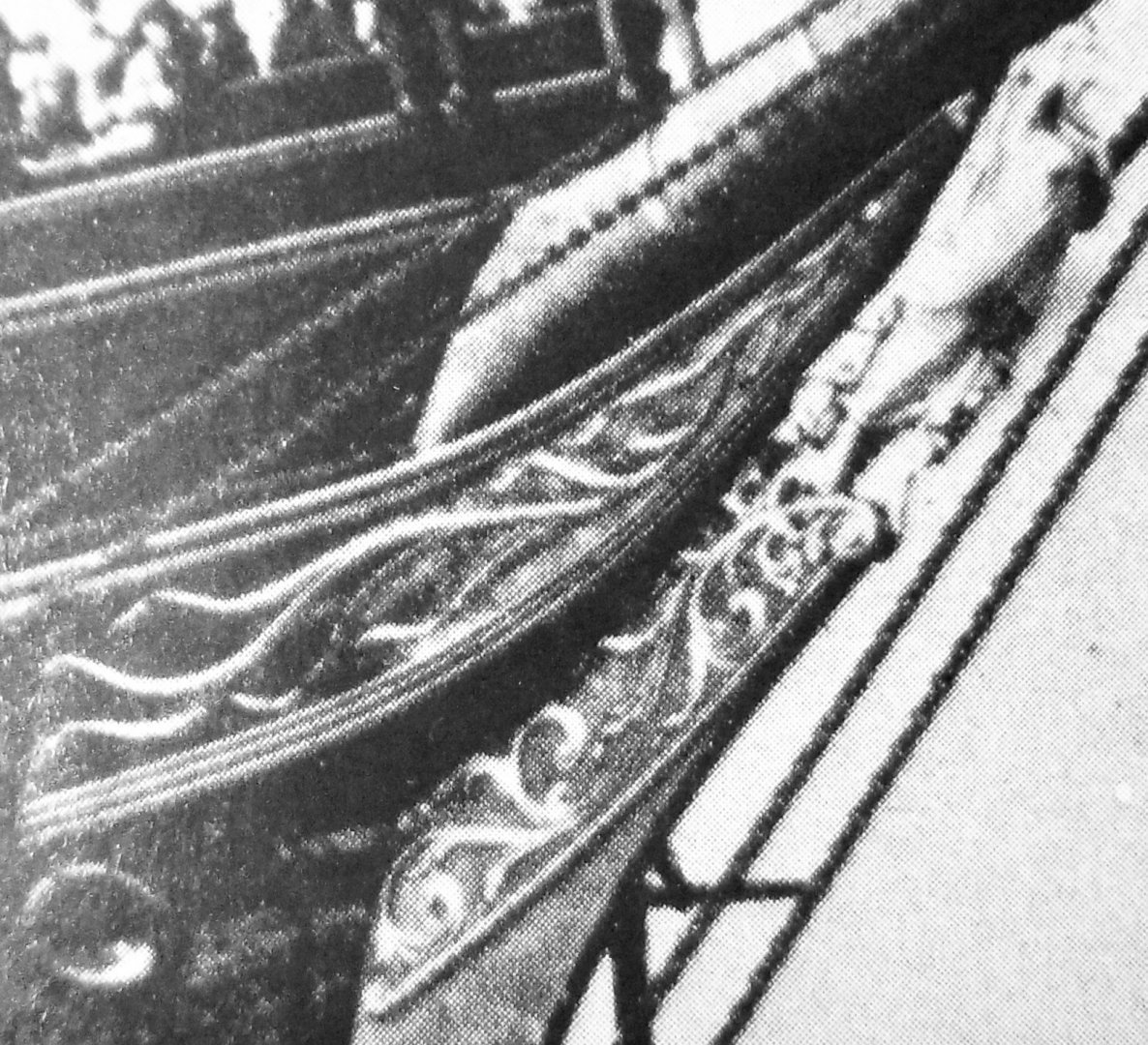
Your presentation is customarily informative Rich. Getting folks to realize that McKay's final clipper embodies the entirety of his clipper design. Apart from her hull proportions and deadrise....the bow/cutwater/hood ingenious design was a common structural feature On all of McKay's clippers. The initial statement of Duncan McLean declaring that Staghound(McKay's first clipper) exhibited a unique design feature never before seen on such models and was a precedent setter. McKay never included this feature on any of his design drawings to protect it from being copied. Every other clipper made...by every other designer/builder...lacked this unique structure(Hood). Rob
-
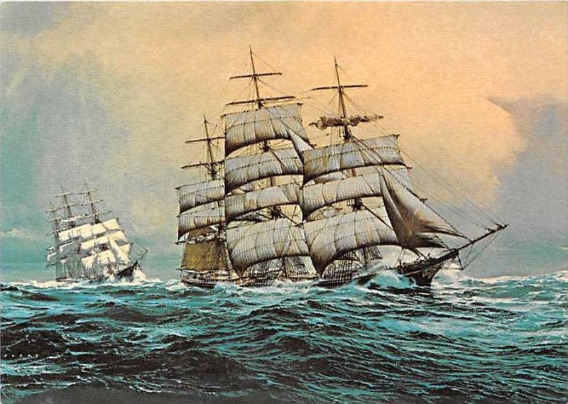
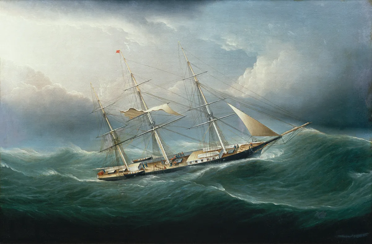
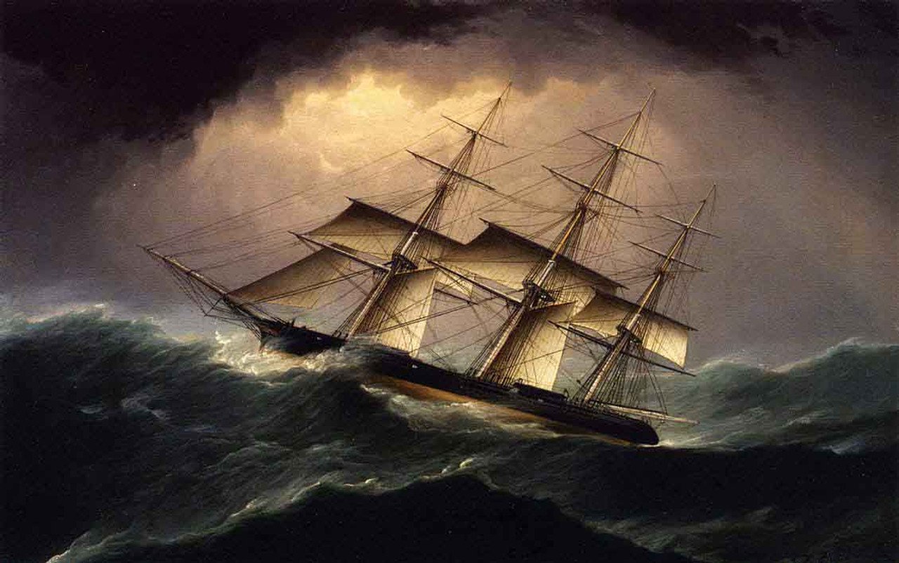
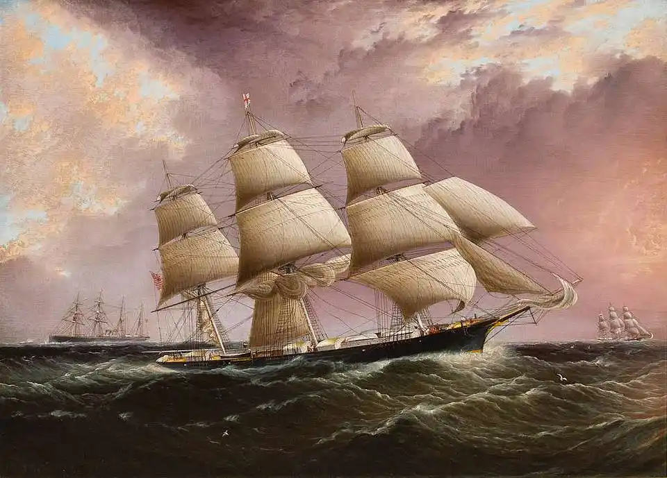
This can be stated as truth. Most records were established during long stints of strong steady weather. The occasional squall and tempest only contributed to calculating overall 24 hour periods....for establishing nautical miles traveled. Setting and striking sails to optimize overall speed was a common and safe practice. Clipper captains were notorious for pushing the envelope...letting out more sail when prudently it was a dangerous move. However, the promise of monetary gain and the prestige of setting a record associated with their name fueled the practice. Paintings of clippers with a full set of sails, to include stunsails, set generally happened in the tropics and when fair breezes beset them, and even then, many skysails were furled to protect their fragility. Notice this famous painting of Glory of the Seas being chased by Young America. Both with reduced sky and royals...to protect against demasting...during a brisk squall. Rob
-
The key element on all of these paintings is the large single topsail. This clue, alone shows us that these vessels were painted before they received their upgrades to the Howes double topsail design. In many cases the area covered by these four sails....ie...main, topsail, topgallant, royal, was sufficient to propel the vessel at a moderate 10~15 knots. It is true, many captains reduced the skysail/yard to reduce stress on the mast....but most paintings we see do not depict vessels in such a dreadful affair. Some paintings that do depict such an extreme weather condition, also show damage to royal and topgallant masts...not to mention loss of said yards and sails. Hauling down skysail yards were a routine practice....however, some first hand descriptions from Duncan McLean, report that many of McKay clippers were originally only fitted out with royals. One can assume, skysails were added later to aid in achieving greater speed. Clipper Lightning achieved some of her record speeds, while missing her skysails during a particularly horrific passage. When modeling any one particular vessel...it would not be inaccurate to depict her with or without skysails. Dependent, on the era you are modeling your clipper. I would fully encourage anyone not familiar with Donald McKay's remarkable naval hoods, to look up clipperfan..(Richard Jones), for his full explanation and research on the matter. He and I both agree...McKay built all of his clippers with this structural feature. It was his trade secret and he even asked artist to not paint it on his vessels to, in essence not reveal it to any competitor. There is much evidence provided by Duncan McLean in his first hand accounts to verify the structures presence on McKay clippers. Glory of the Seas is a fine example. We have loads of evidence this fact s true, if one cares to dig deep enough to find it. The simple fact that model kit designers leave it off their kits, is evidence they are not familiar with Donald McKay's ingenious design and application. Following paintings of the time cannot be your only source. Enjoy. Rob
-
It's your build log....so misdirection can be as fun as the topic. I'd simply like to say, you've done wonderfully on her...and in sucha large scale too. Can't hide any details....or missteps. your rendition is magnificent. Have you not discovered the unique McKay naval hood discussion? Most model designers simply glue the figureheads of FC and FF against the cutwater, under the bowsprit. McKay developed a unique *Hood*, that secured the cutwater to the stem providing extreme rigidity and provided a sturdy pedestal for the figurehead to rest up against. Note McKay's famous last clipper....Glory of the Seas, to see this unique fixture. It was unique to McKay clippers. One of his *secret* design features. Rob
-
Wonderful....just wonderful. You're going about this all too precisely. . I'm very much impressed with your application and skill. This scale lends itself well to your ability to replicate details accurately. One reason why I stick with 1/96. My patience and laziness find their limits there. Rob
- 103 replies
-
- 1
-

-
- Cutty Sark
- Sergal
- (and 1 more)
-
Thanks Trever.........your description is spot on. However accurate,.... that description was not my point. Observers today, only have CS as their reference point. Not knowing, that as amazing as she is...compared to American clippers, She would not command said amazement, if there where an American clipper available to float next to her. She would be dwarfed by the shadow of her American sister. Similarly,... large refractor telescopes draw more emotion and amazement...then similar aperture reflector telescopes, set up on the same field. Designed for different viewing, but still, the long focal length refractor will command greater adoration. Oh....just a side note. Donald McKay felt his designs were most advantageous for the tea trade as well....knowing, British owners,(who purchased many of his clippers), would eventually use the vessel for said trade. It's just one of many opinions I have.😁 Rob
- 103 replies
-
- 2
-
-
- Cutty Sark
- Sergal
- (and 1 more)
-
Your build of CS is masterful. your attention to detail is second to none. I am amazed at just how small she was compared to her Larger American sisters. Rob
- 103 replies
-
- 1
-
-
- Cutty Sark
- Sergal
- (and 1 more)
-
Sorry to hear the lower channels didn't work out for you...though I do see them used in your mock-up. I'm still not clear on how they are trouble for you....but to each his own. Each modeler is guided by the level of authenticity they are able to tackle. Personally, I draw the line at being a purist, by being captive to only using wood for the construction of my models. I use whatever suites me. Knowing full well that a good coat of paint will disguise whatever sacrilegious material I employed. Your model is stellar and you have constructed her skillfully. Rob
- 200 replies
-
- 1
-
-
- Flying Cloud
- Mamoli
- (and 1 more)
-
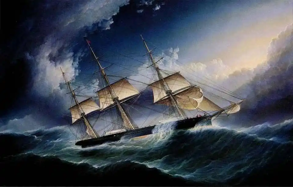
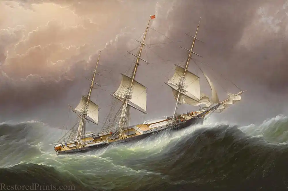
It does. It shows a number of other inaccuracies as well. Let alone the scale issue of the men and equipment.. My point was not to point out inaccuracies of the ship, ...but the similar technique used to form the water and waves. Note these other Buttersworth masterpieces.

-
I concur that she had 5 yards per mast...generally. Lowering skysail yards and all the rigging associated with it was a difficult task....not to mention, done hastily during a sudden squall or during a stretch of severe weather. It was a common practice to do so when entering long stints of extreme weather....namely rounding the horn.....or below the 49th parallel, .to reduce these fixtures to prevent the trouble of demasting. In lighter fair...(Tropics), these yards, along with stunsail booms were added to capture the slightest of breezes. Both of these Buttersworth paintings depic, vessels in squalls or extreme weather. Hence the shortened rig. One last note: When many of McKay's vessels were originally launched, they were only rigged with the highest being Royals...because the area was the same...just, that the sails were larger. As sail plans and designs evolved...double topsails were added, topgallants, even upper and lower topgallants, royals with skysails and extreme moon sails topped off the plan. Crazy. Rob
-
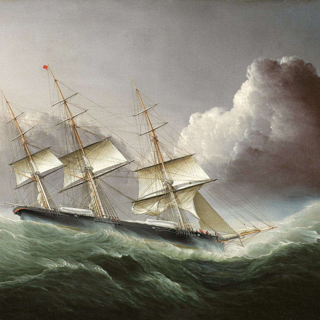
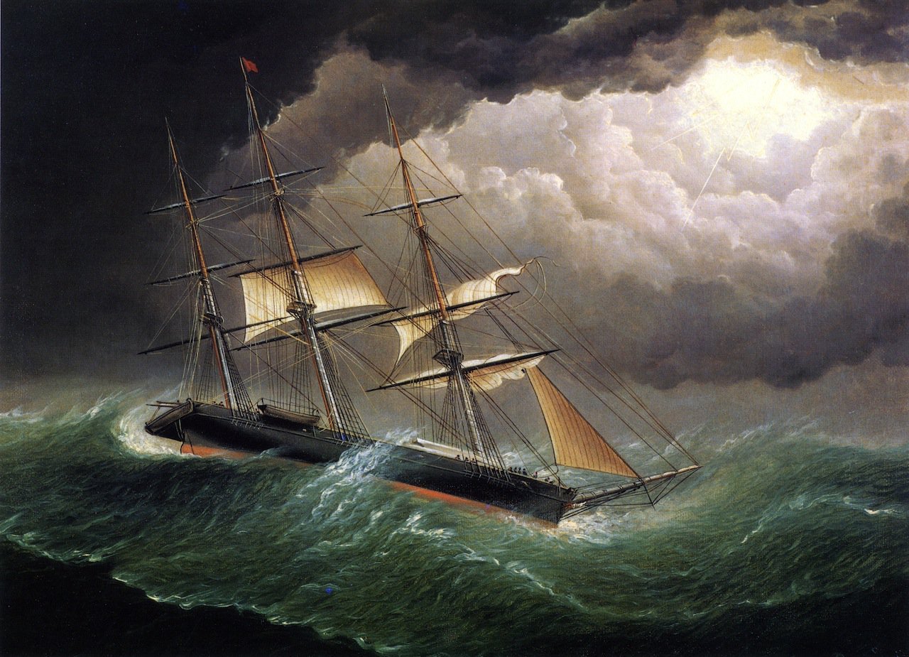
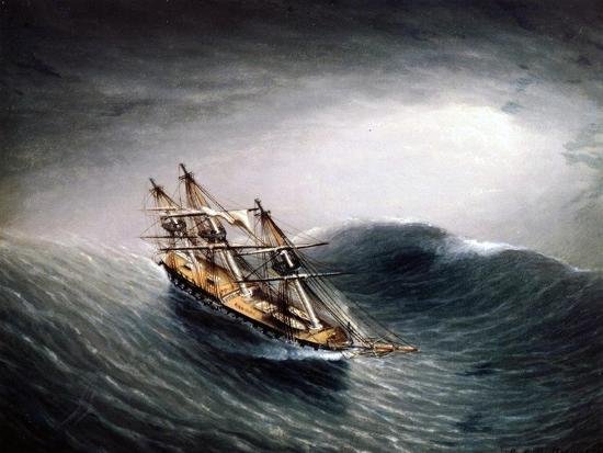
Trever. Unlike reefing double topsails...a large single topsail, was reduced in size, by lowering the topsail yard...nearly too, or upon the top cap. This permitted the sail to be reefed via the reef tackle, drawing the sail up to the lowered topsail yard, causing the upper half of the sail to flop over the lower half of the sail....reducing its effect. this same action was produced by splitting the sail into *Upper and Lower* topsails...via the Forbes and then the Howes double topsail designs. In this painting, Buttersworth depicts this single topsail reefing quite accurately. Once the vessel has slowed sufficiently to allow the pilot to board....the topsail was released from reef and was fully set to again clip along nicely. This vessel has only 4 yards per mast. Main course, topsail, topgallant, royal. I plan on recreating my Staghound in this arrangement. Rob
-
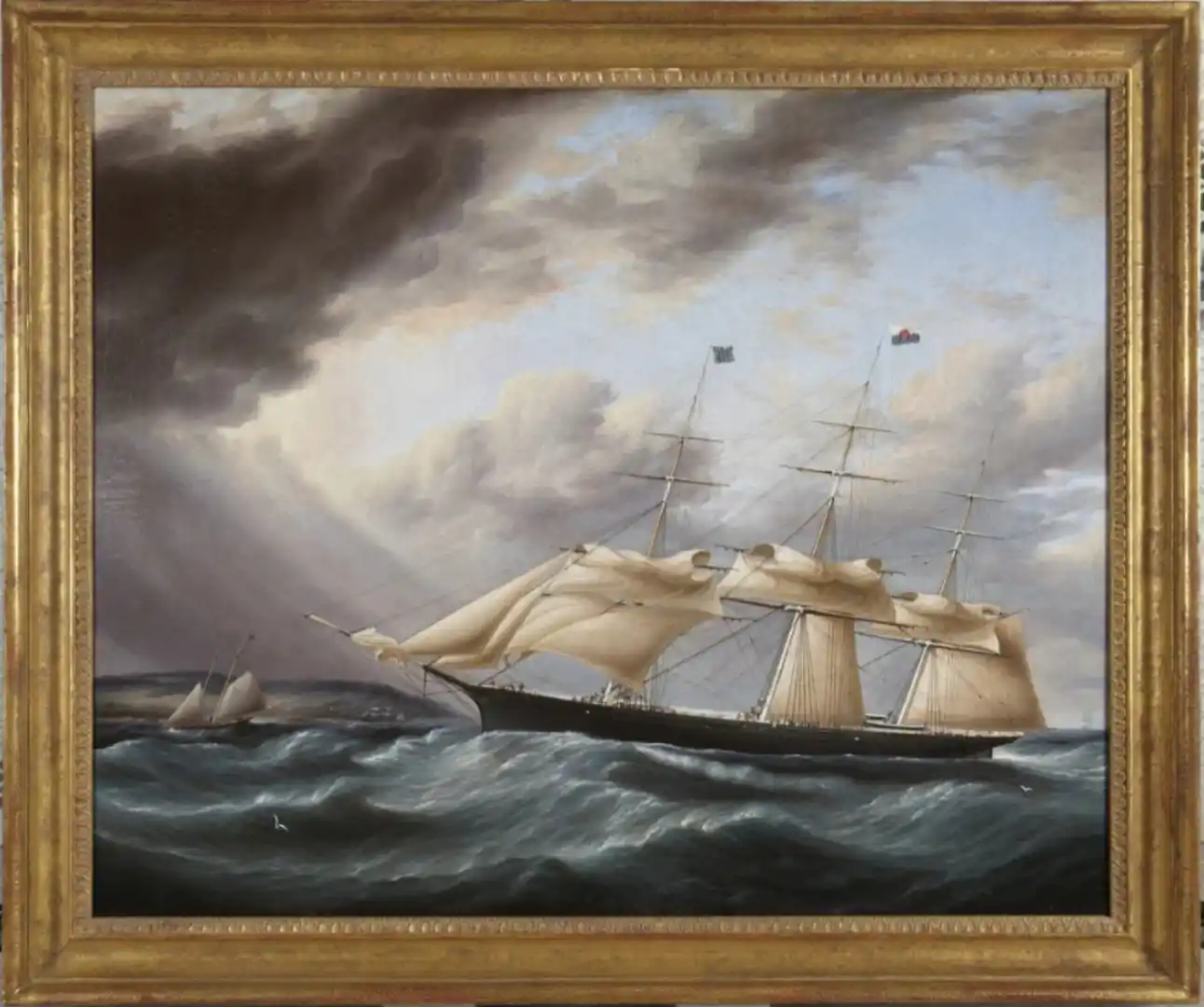
Buttersworth water is a sign of authenticity. Note this ocean of Flying Cloud by Buttorsworth. Same as the above painting.
-
Staghound only had topsails. Upper and lower topsails came with the new Howes design for topsails. This image/painting depicts her clewed topsails. Probably following the description you suggested. Rob
-
Moving along nicely Harry. I break down the process for each mast...to make my brain not default to overload. Your work is looking good. Rob
- 200 replies
-
- 1
-
-
- Flying Cloud
- Mamoli
- (and 1 more)
-
Not sure the Popular Mechanic article is as accurate when claiming that Great Republic had a 180 ft main yard. It was actually only 120 ft. Rob
-
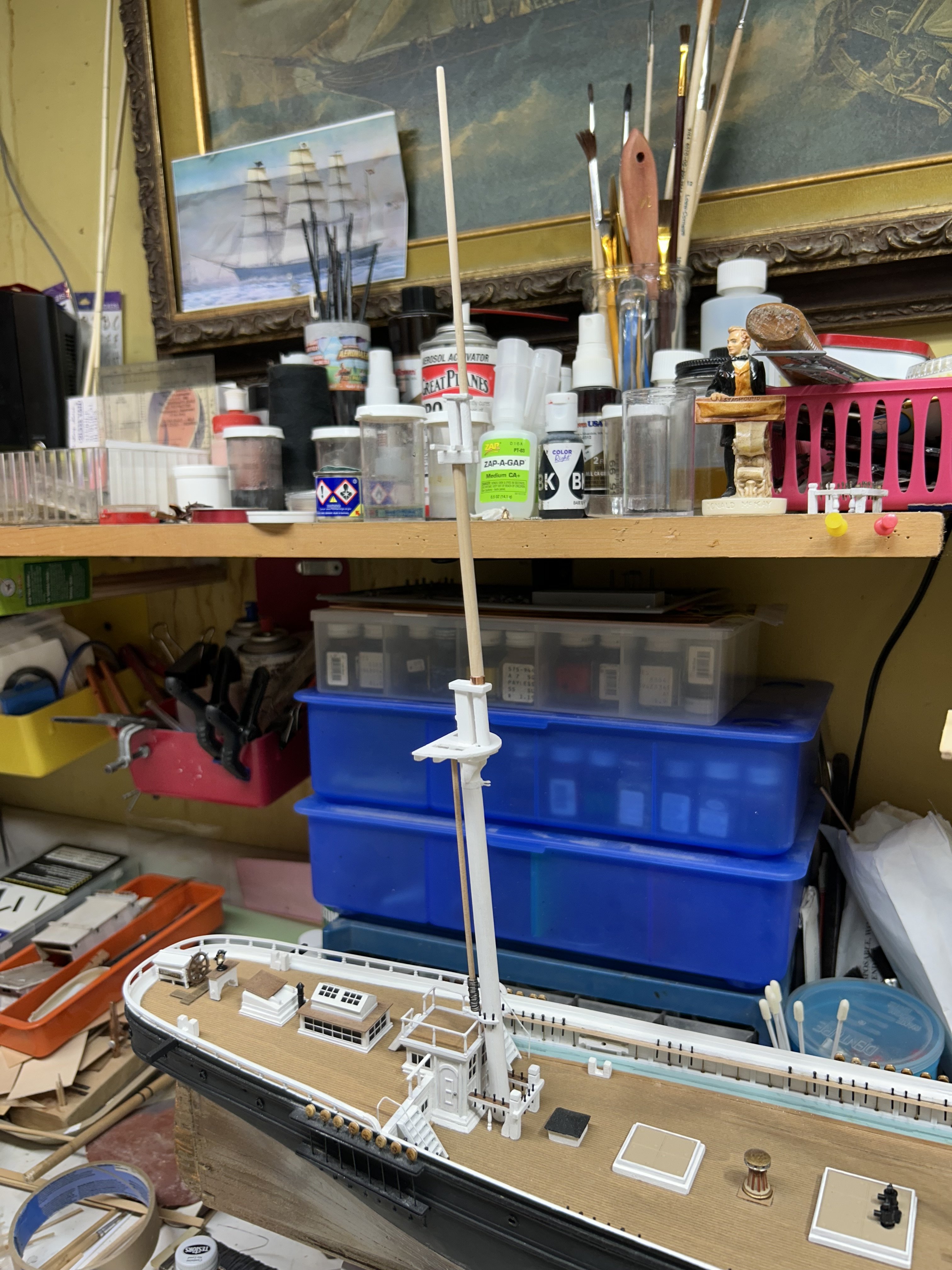
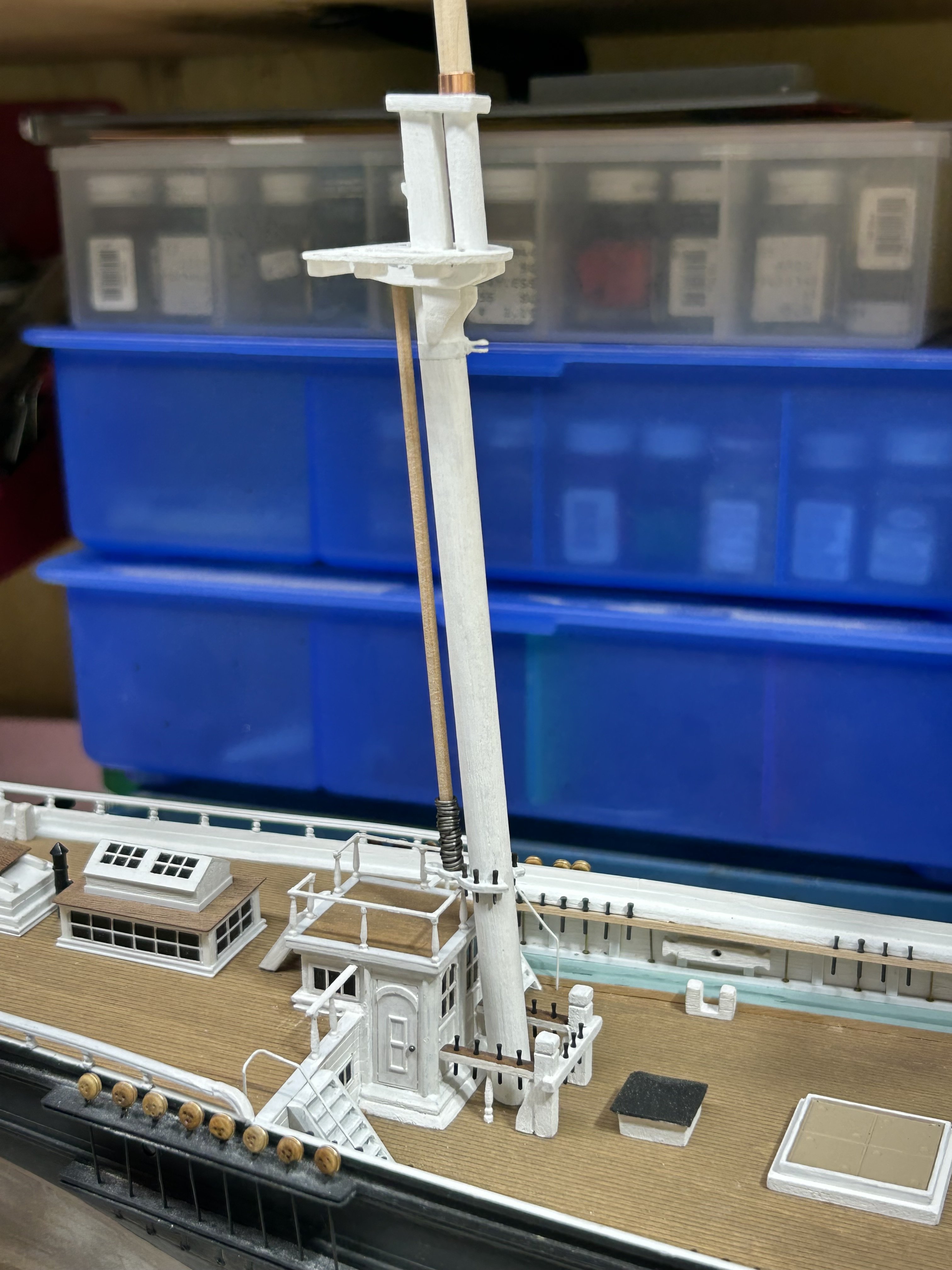
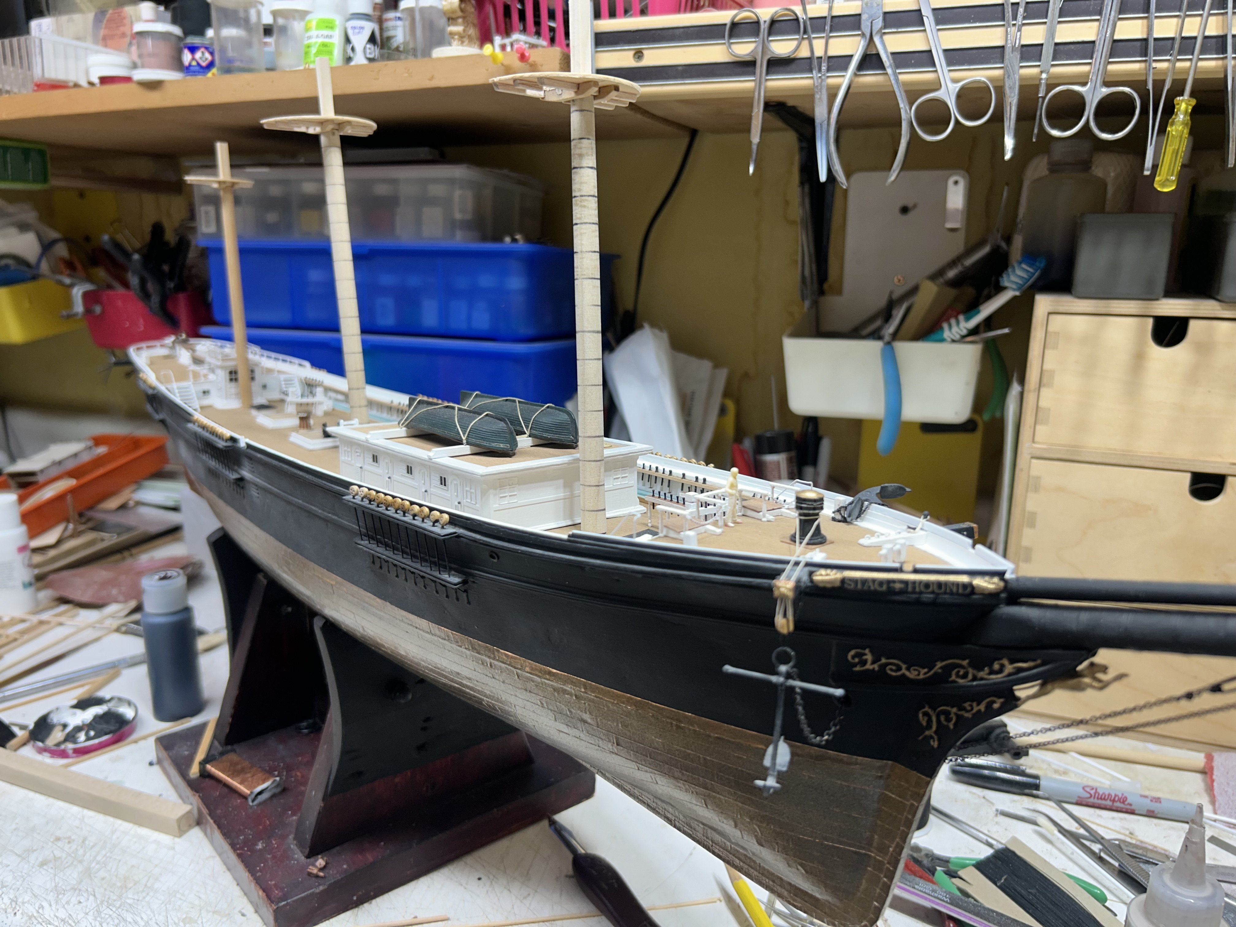
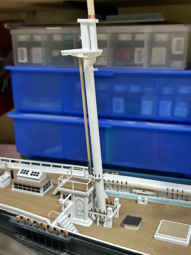
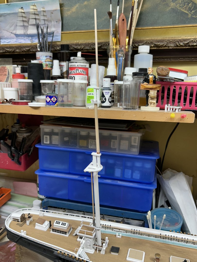
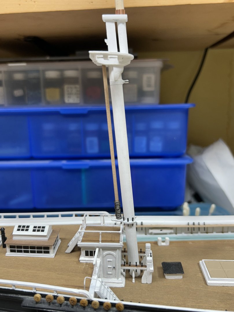
Worked on the mizzen mast today. Still need to rig it with blocks before I begin the yards. Rob

-
I have all my slow and high speed hand pieces rigged up and most of my lab equipment. Makes model making so much fun. Rob
-
We have very little info about her finer details……so, when Rich pointed out my oversight, I had no other option, but to correct it. Thanks for the fine comments. Rob
-
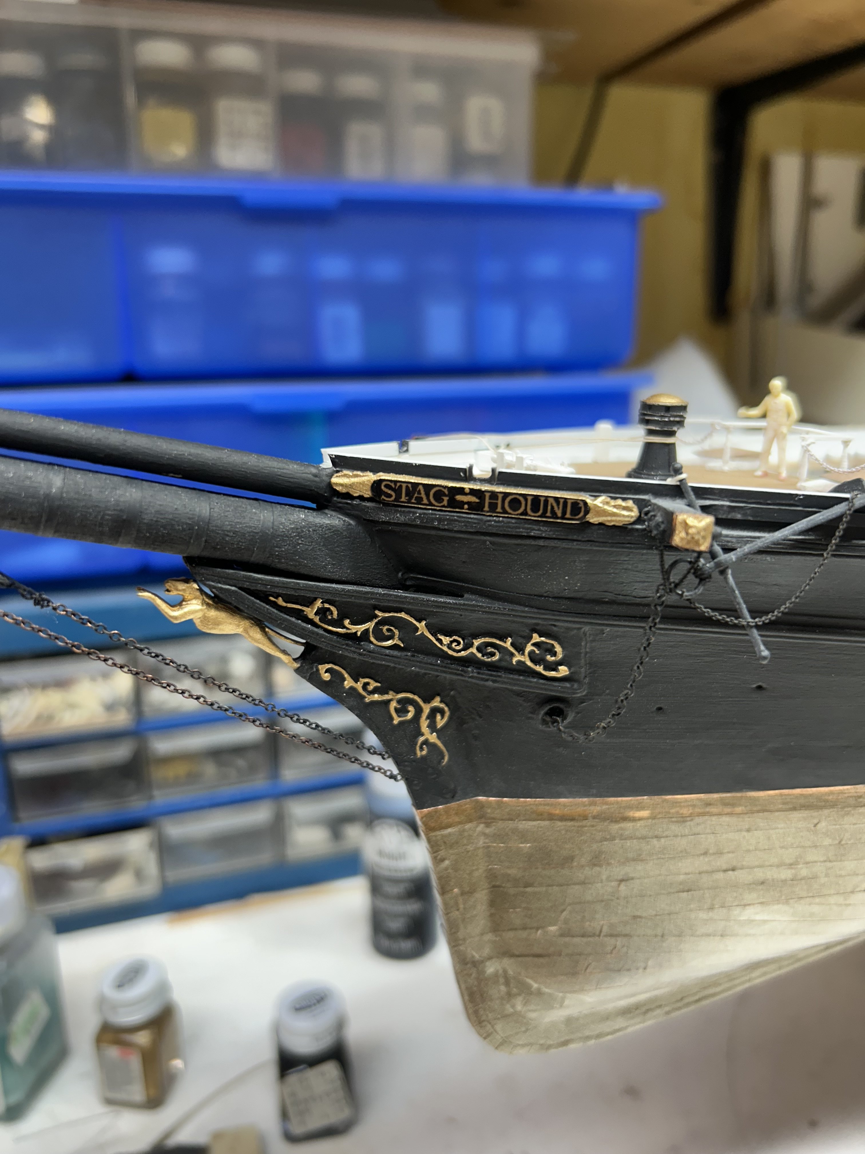
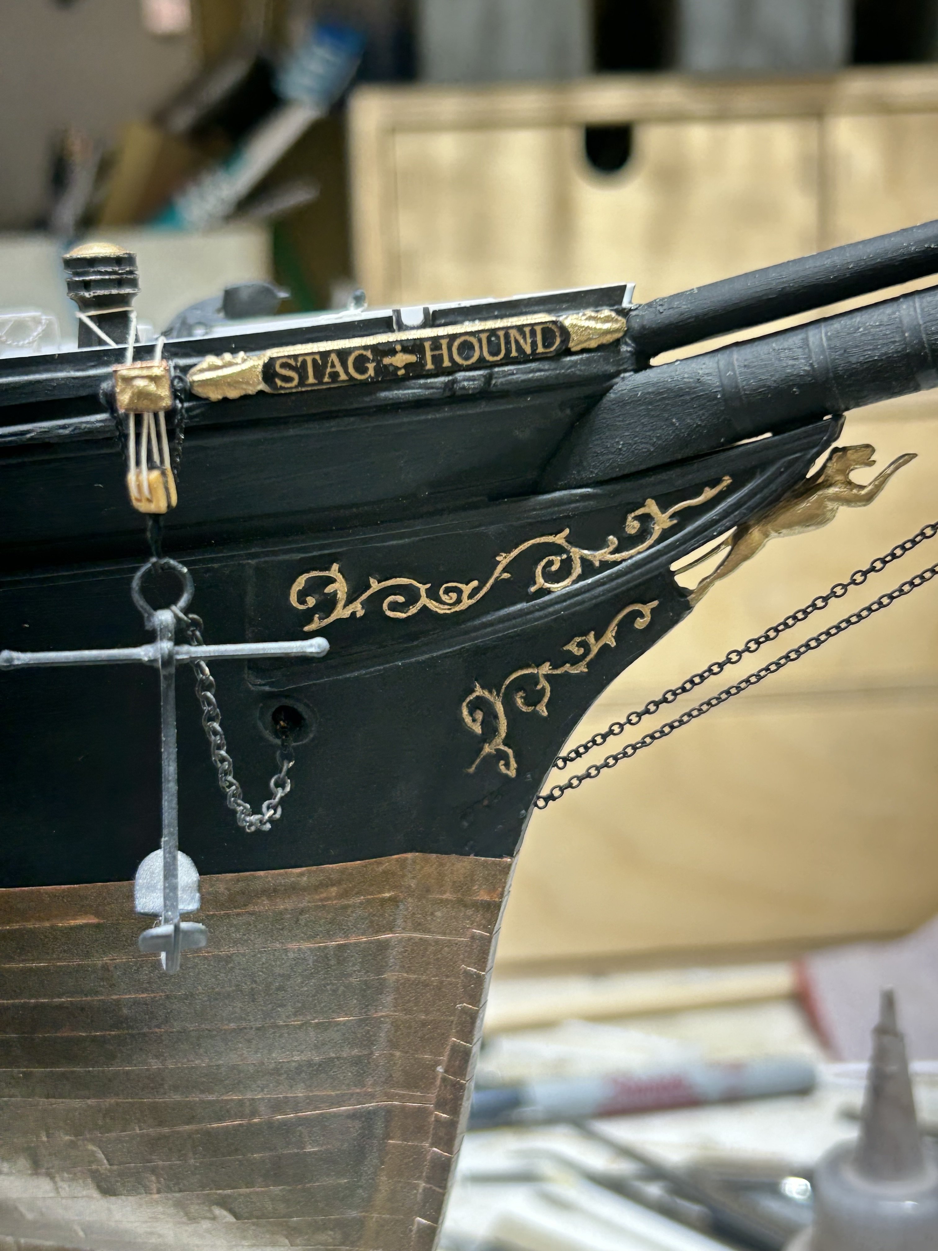
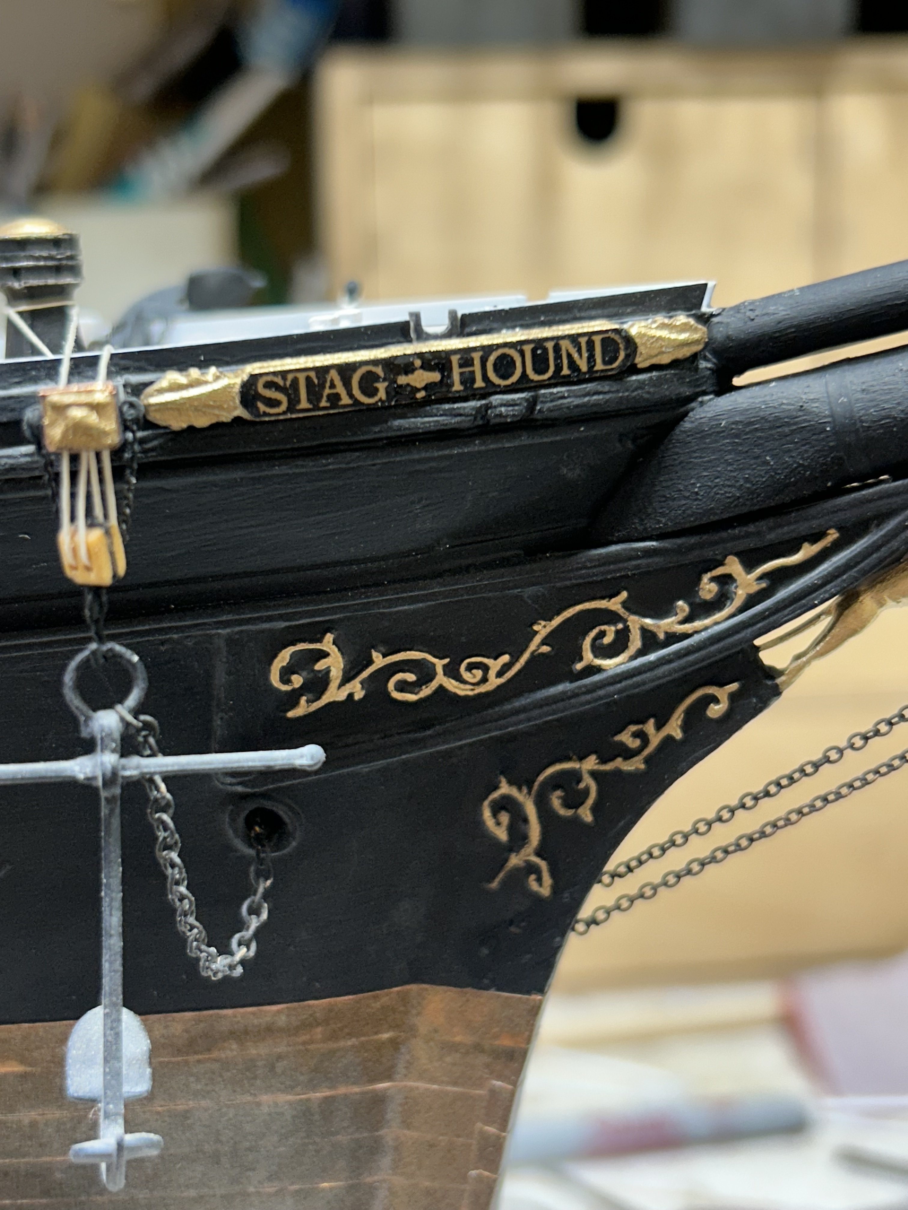
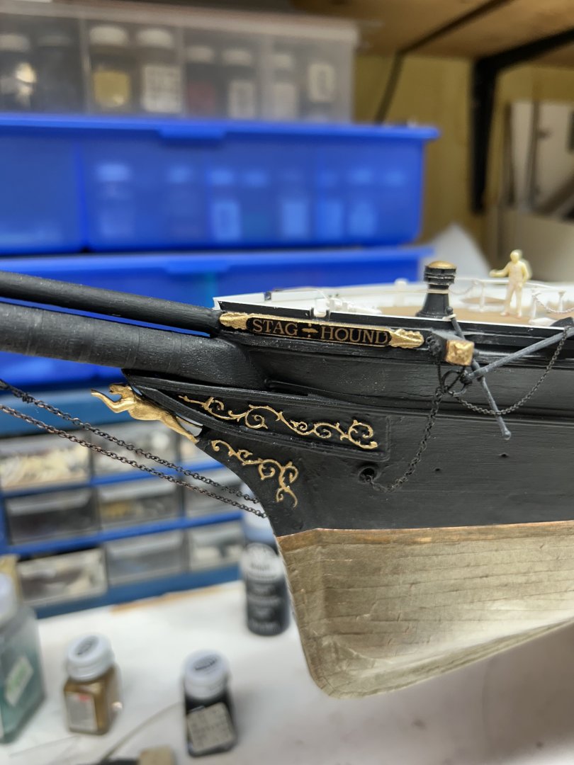
Finished the port side. Rob
-
Wider view

-
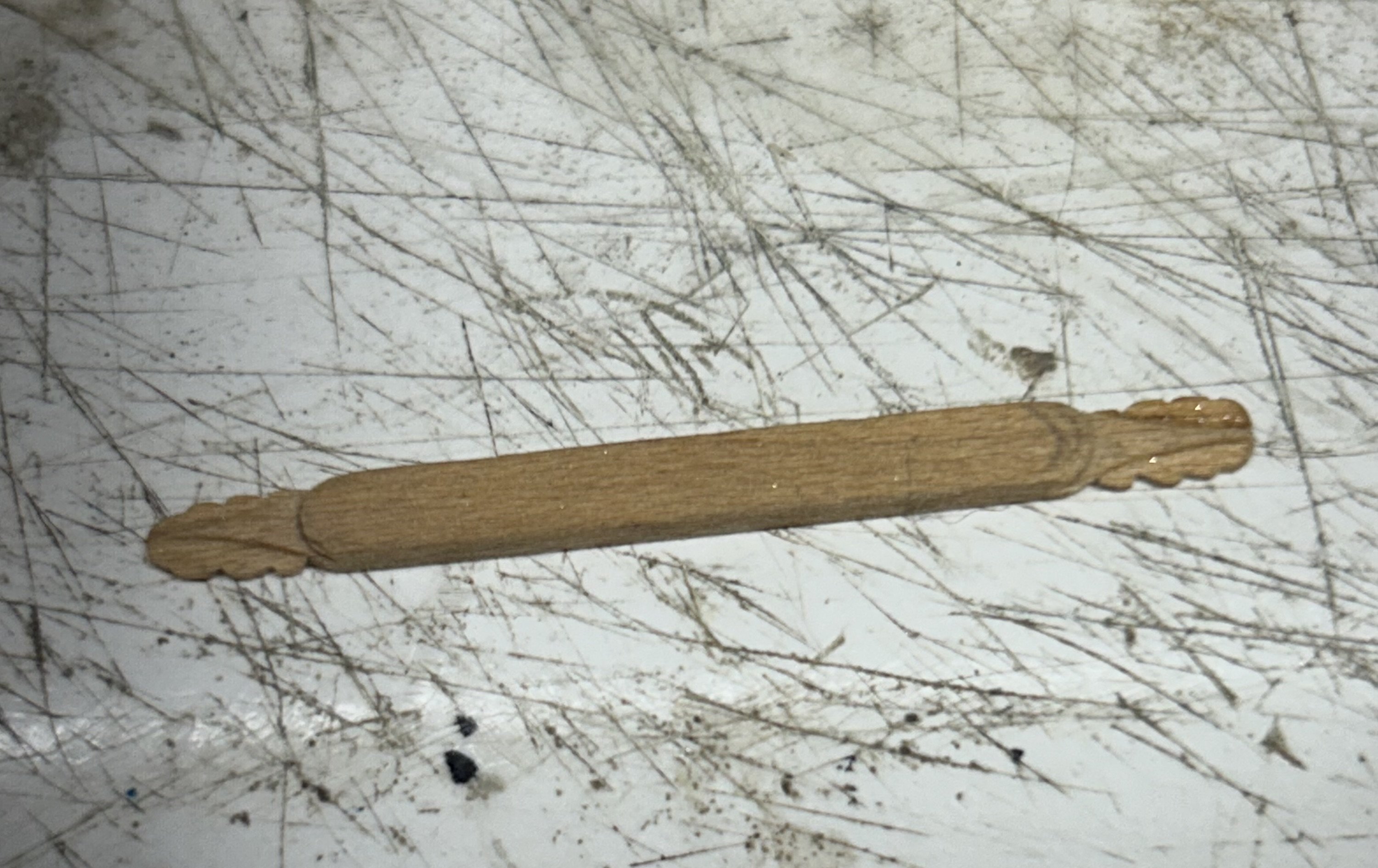
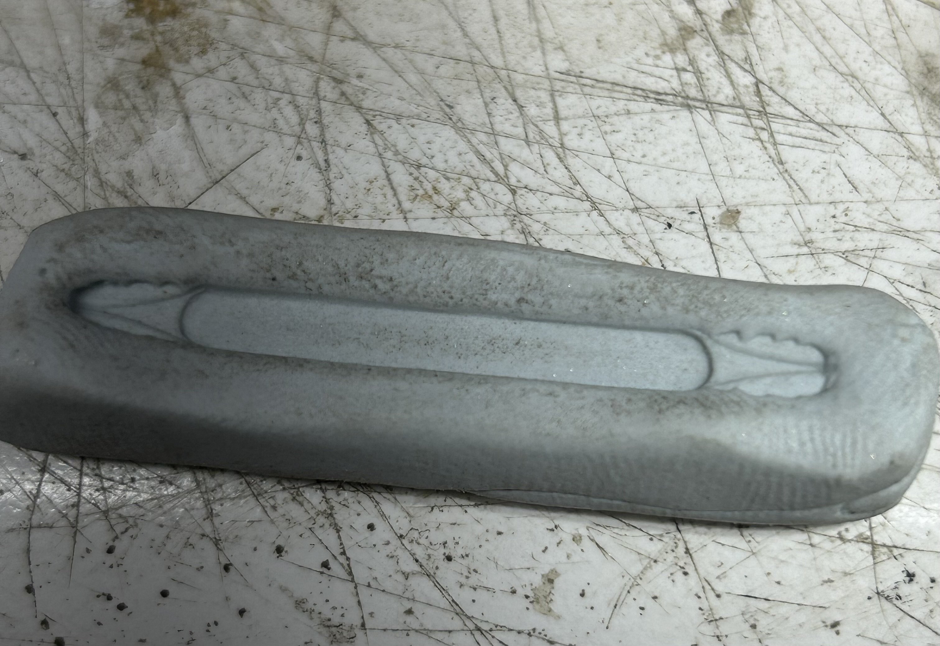
Here is a quick process review of the name boards. I first, carved a wooden name board. Then I duplicated it. Next I formed several duplicates in light cured plastic. Carved them to follow the hull curvature, painted and added premade printed name plates. After Rich reminded me that her name was actually two words, I remade the starboard name board with a golden decorative break between the words. Rob