rwiederrich
-
Posts
5,520 -
Joined
-
Last visited
Content Type
Profiles
Forums
Gallery
Events
Everything posted by rwiederrich
-
I’m sure the brass was tarnished when she was owned by the Portuguese. They let her go pretty badly. Maintenance wasn’t their gig. Rob
-
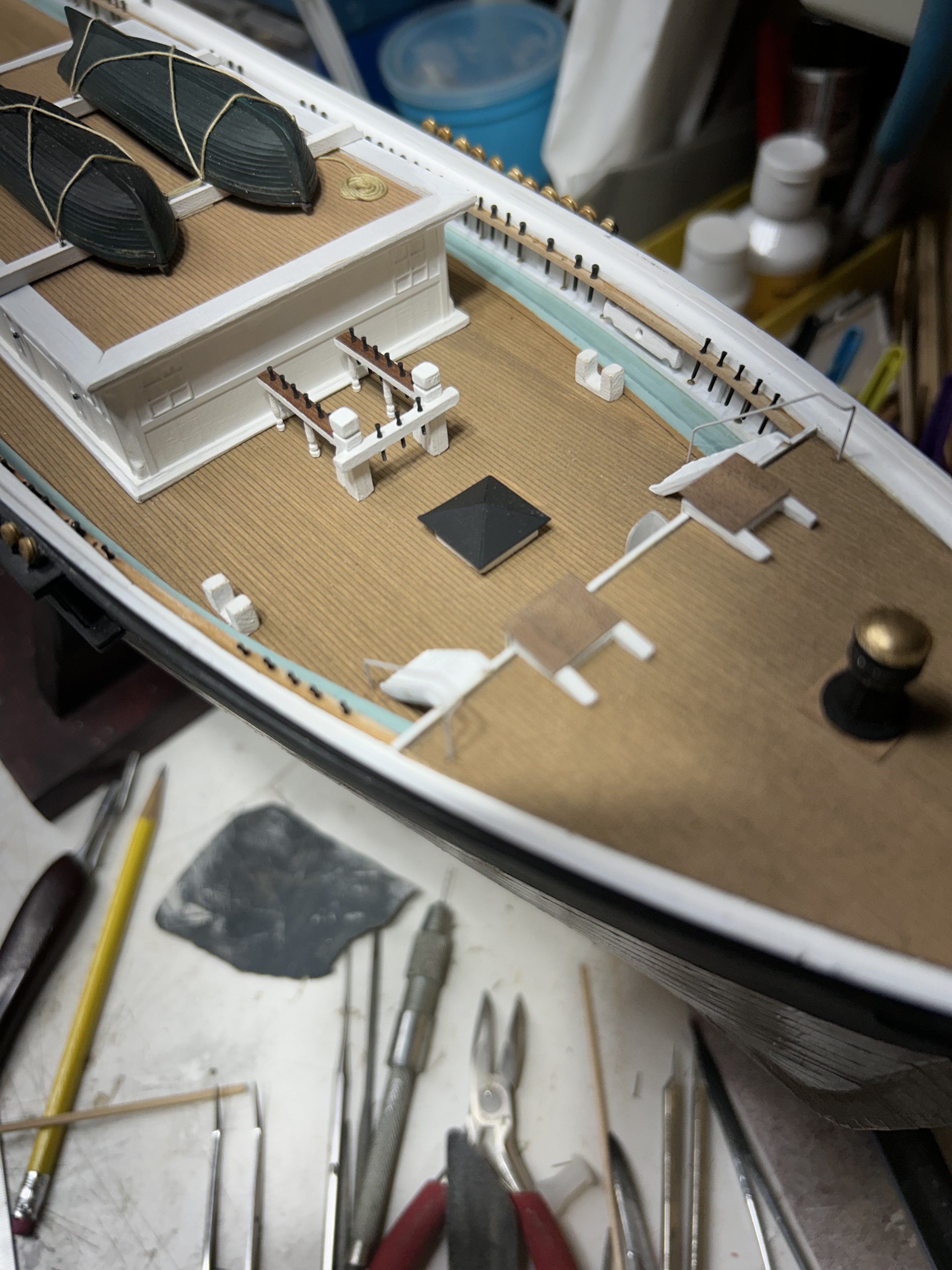
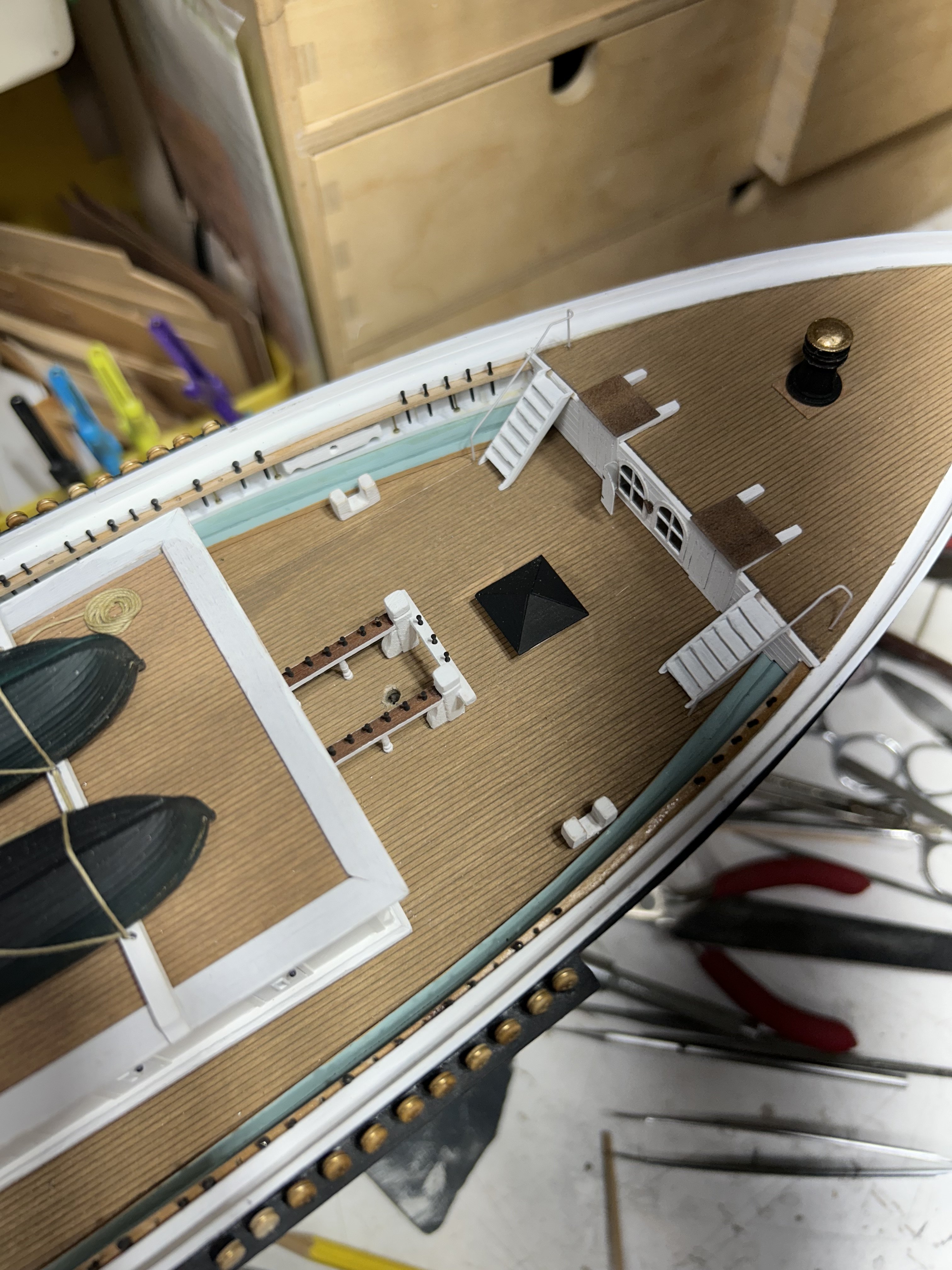
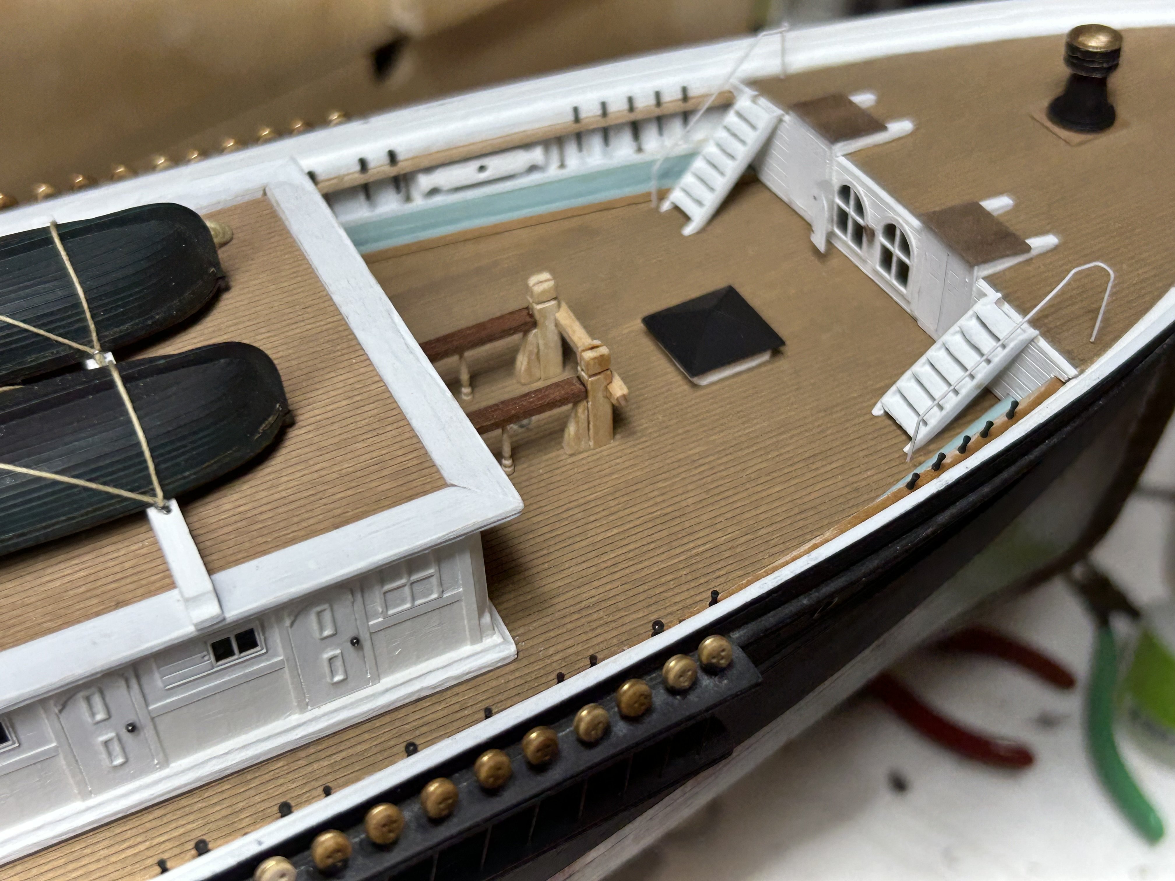
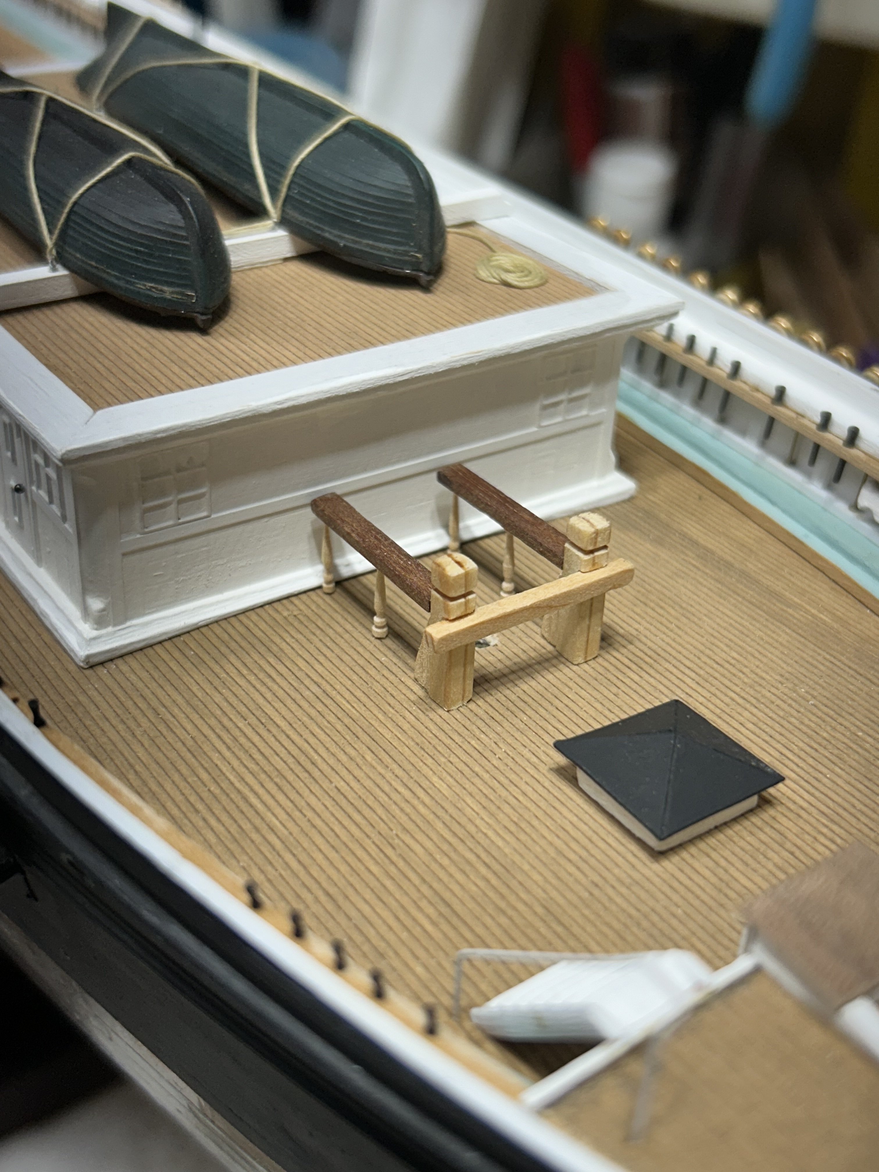
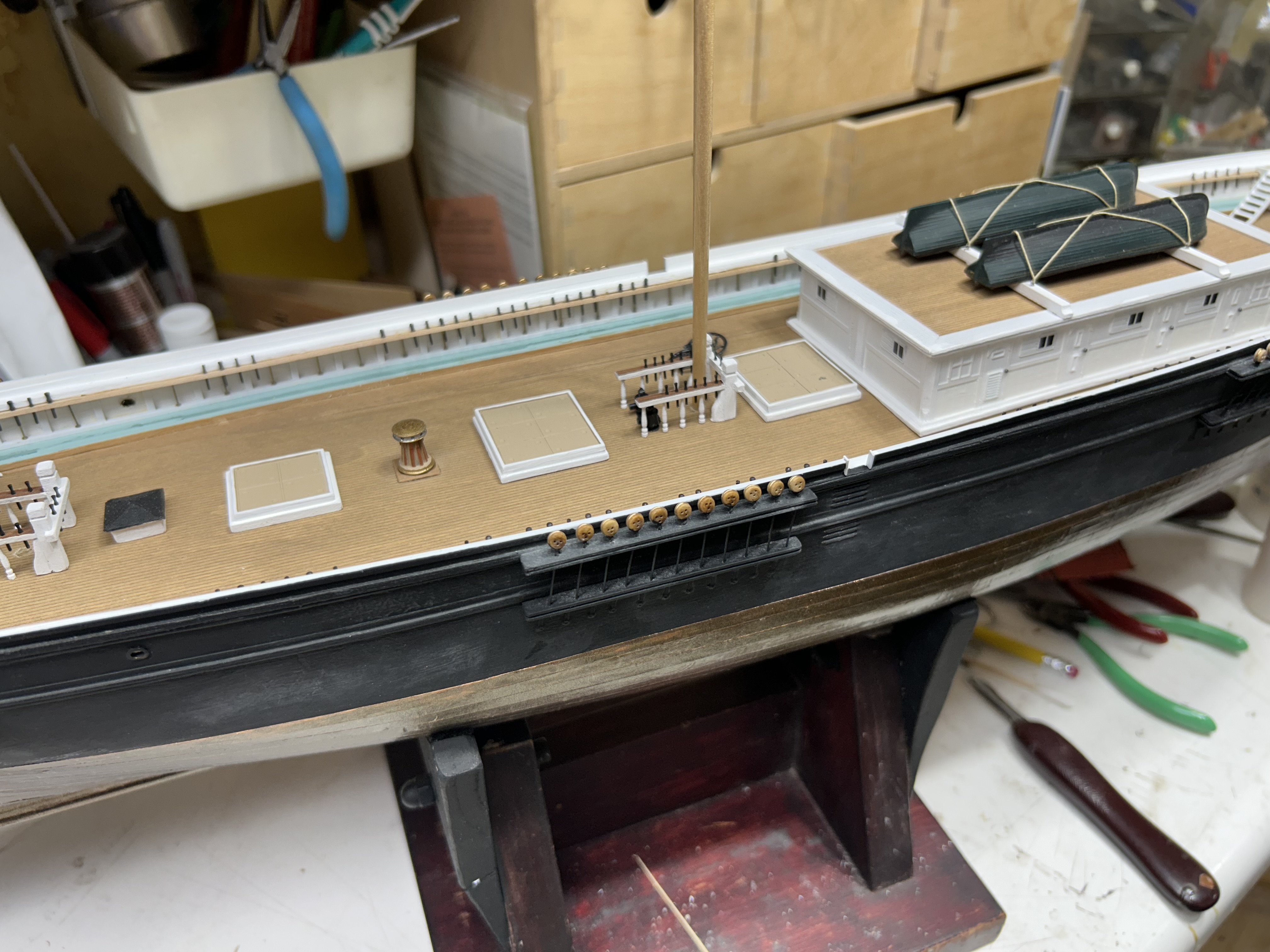
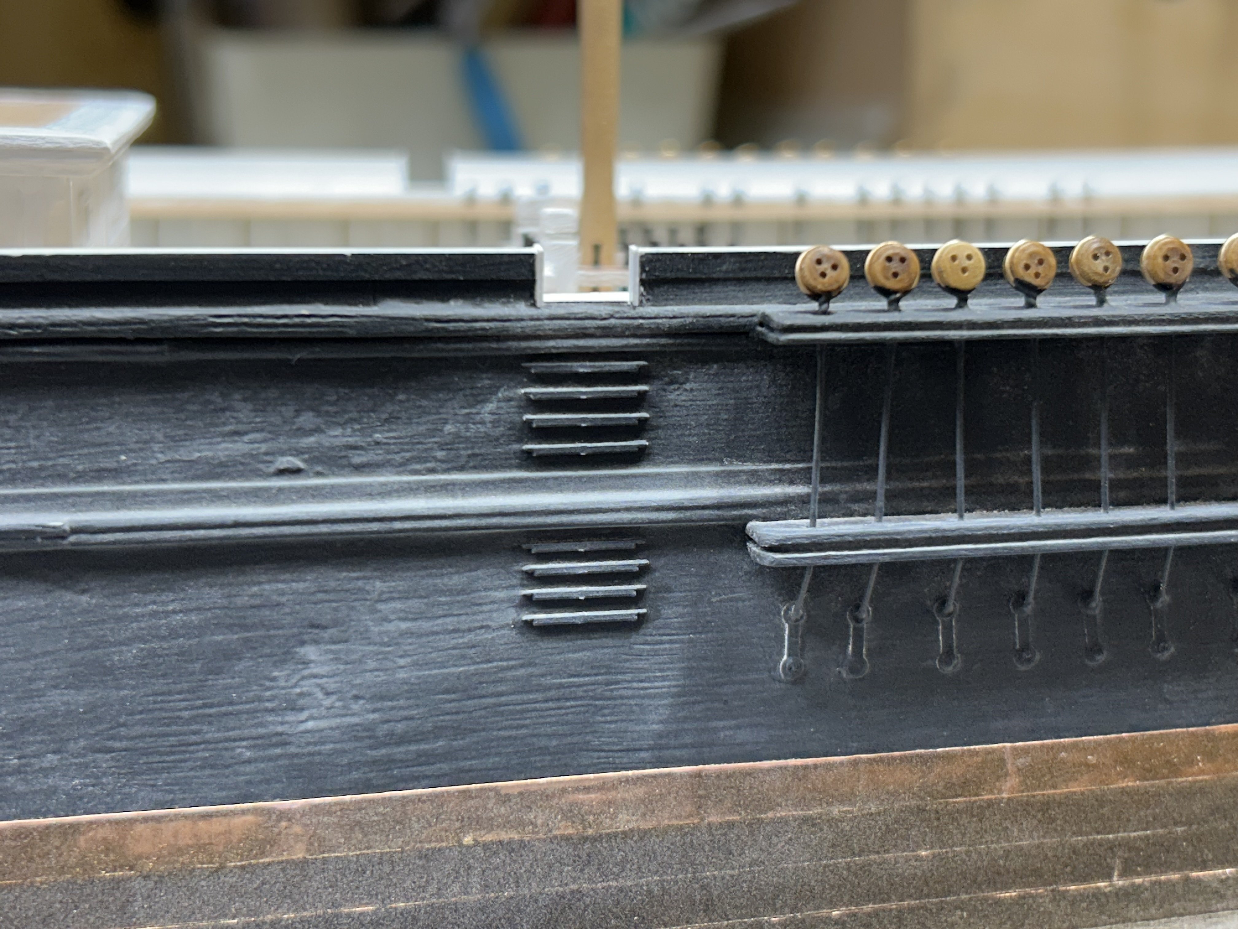
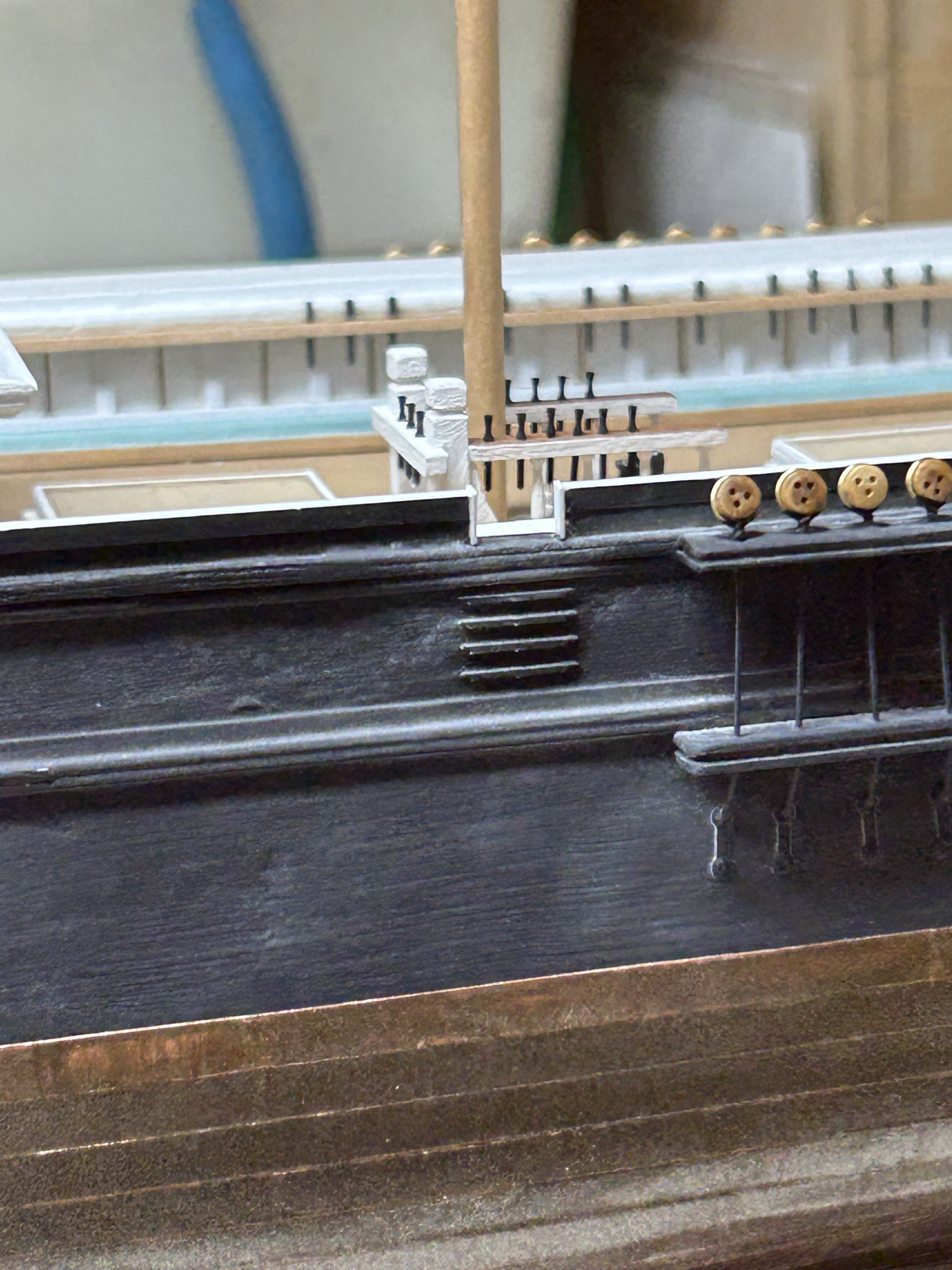
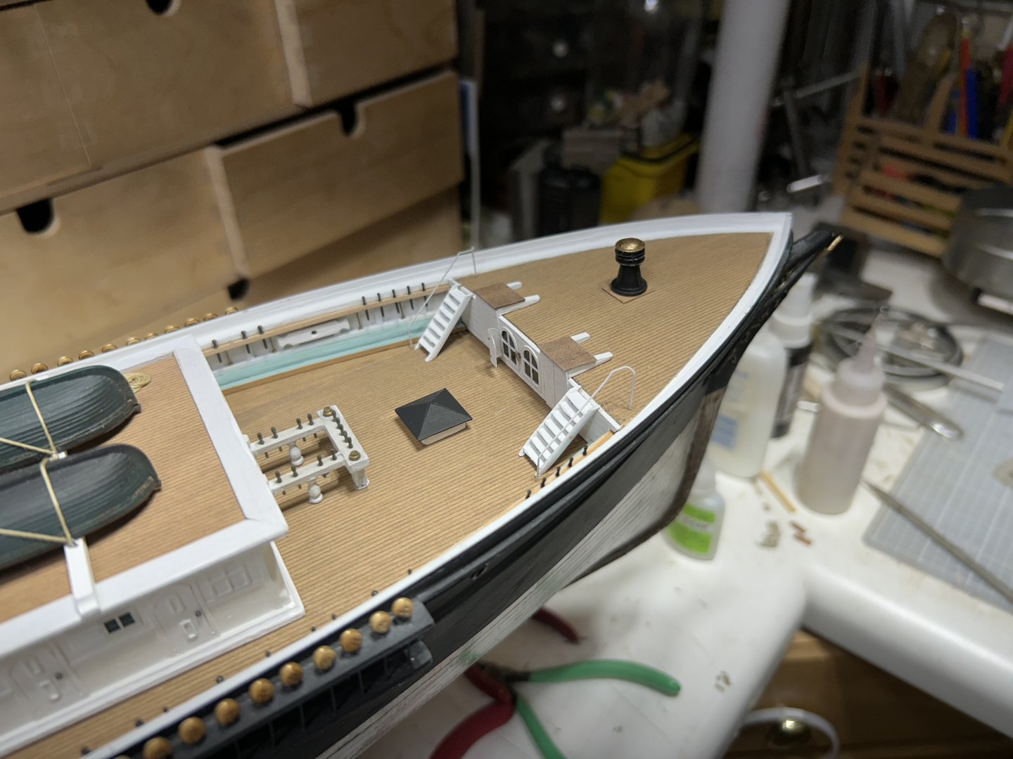
Thanks Rick. Now to the bumpkins and their bits and poop step iron rails. Then finally, onto the forecastle details. Which will be an entire job in of itself. Rob
-
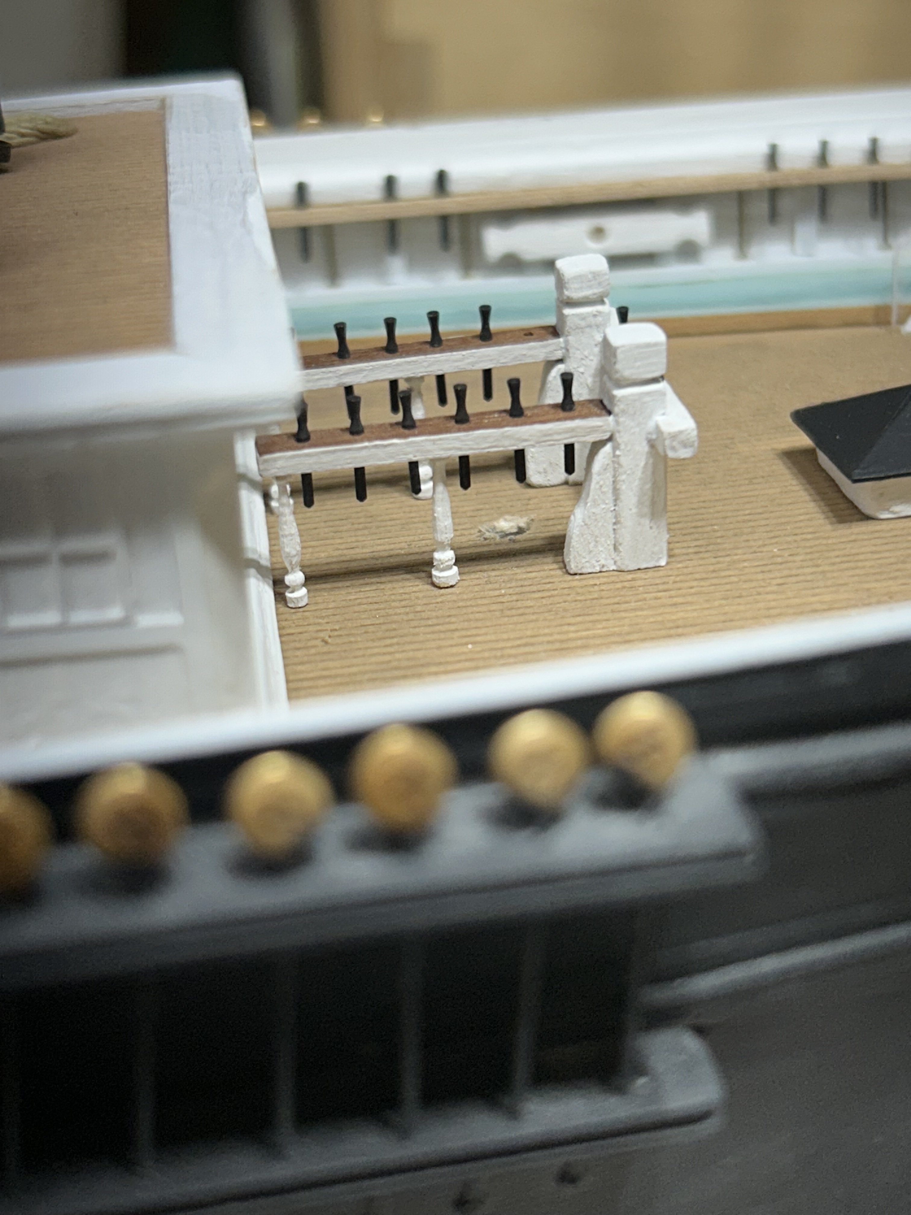
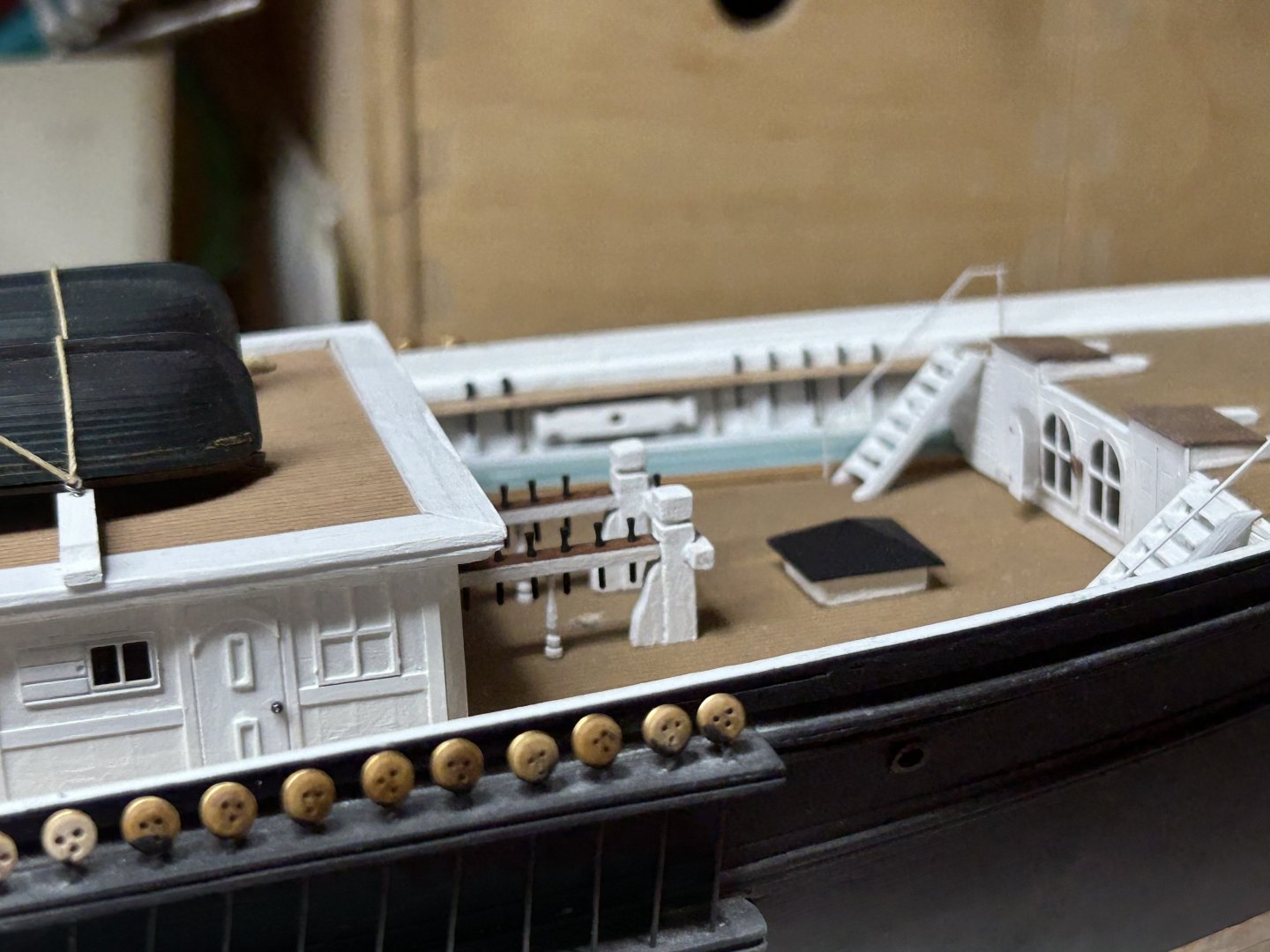
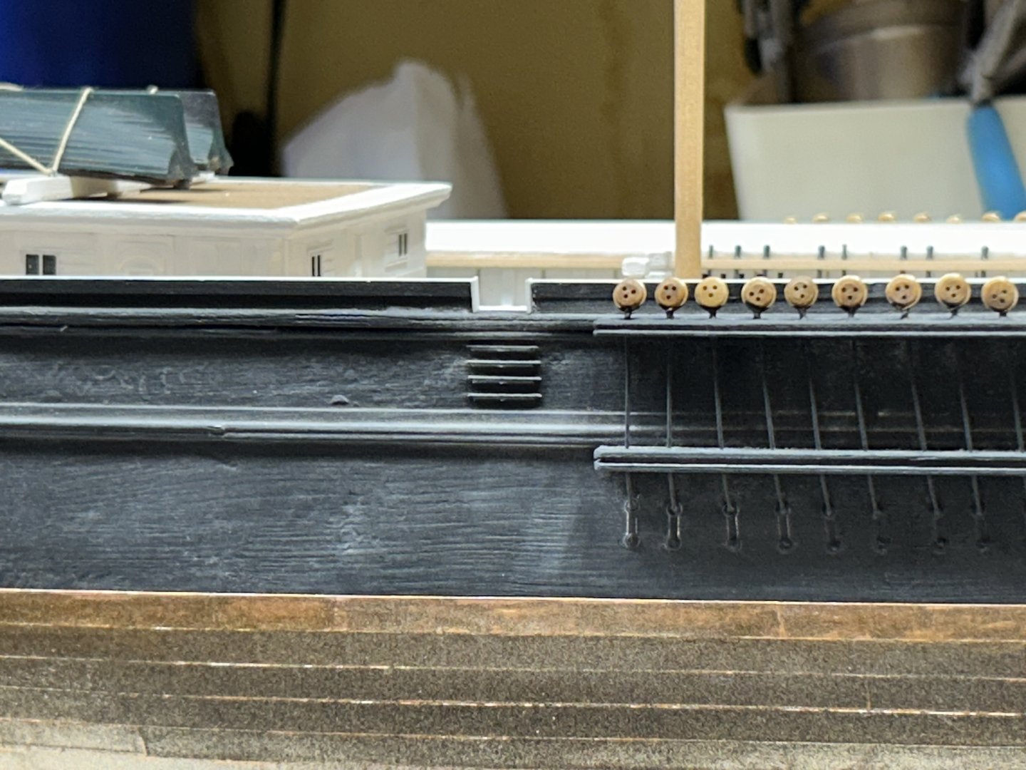
Mooring bits. Rob


-
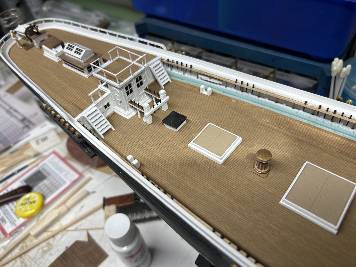
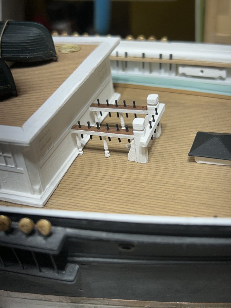
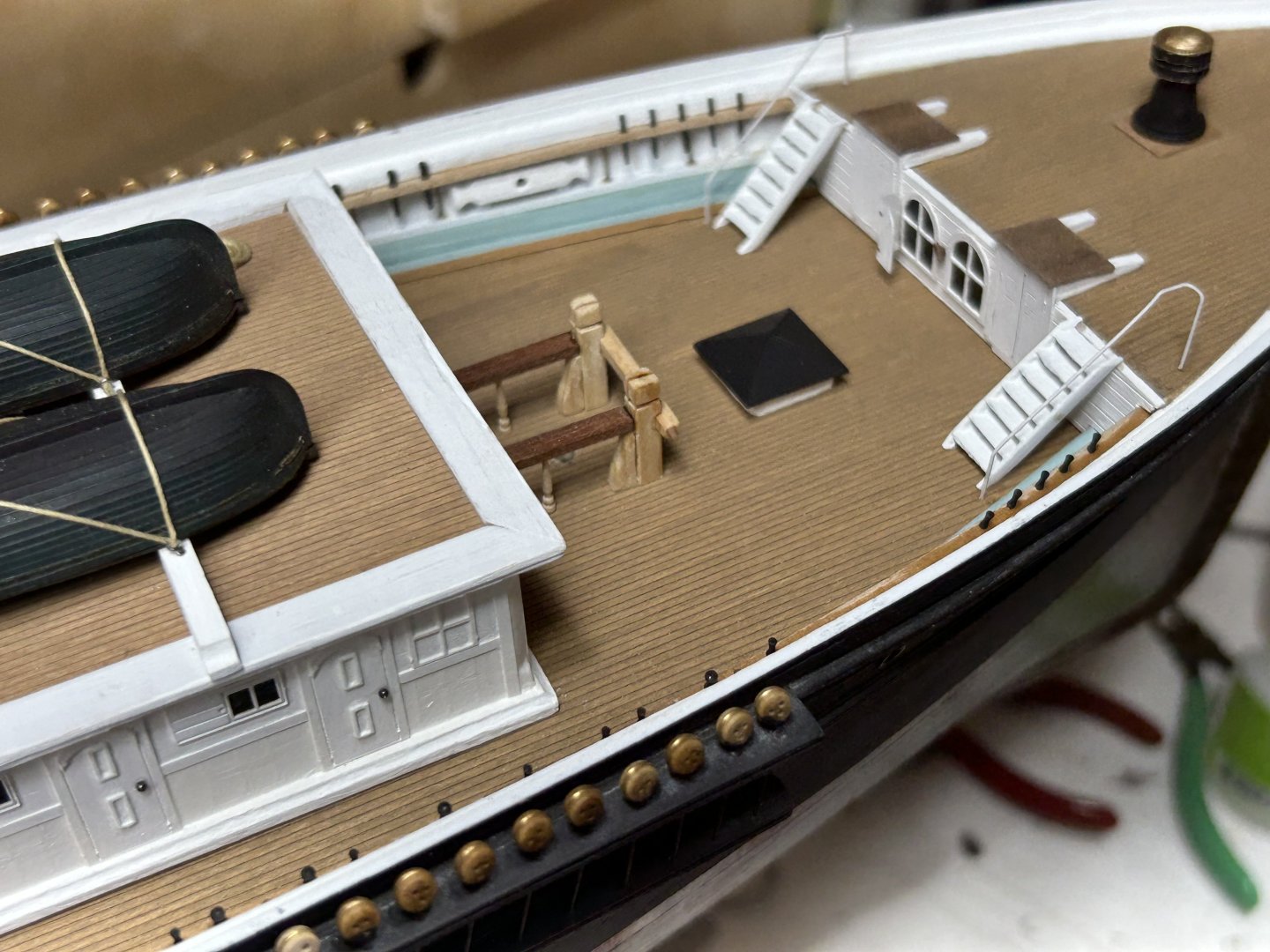
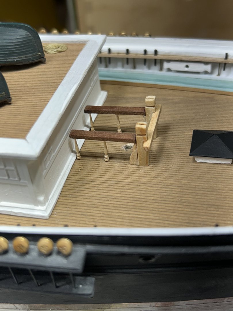
Finished the fore fife rail. Rob

-
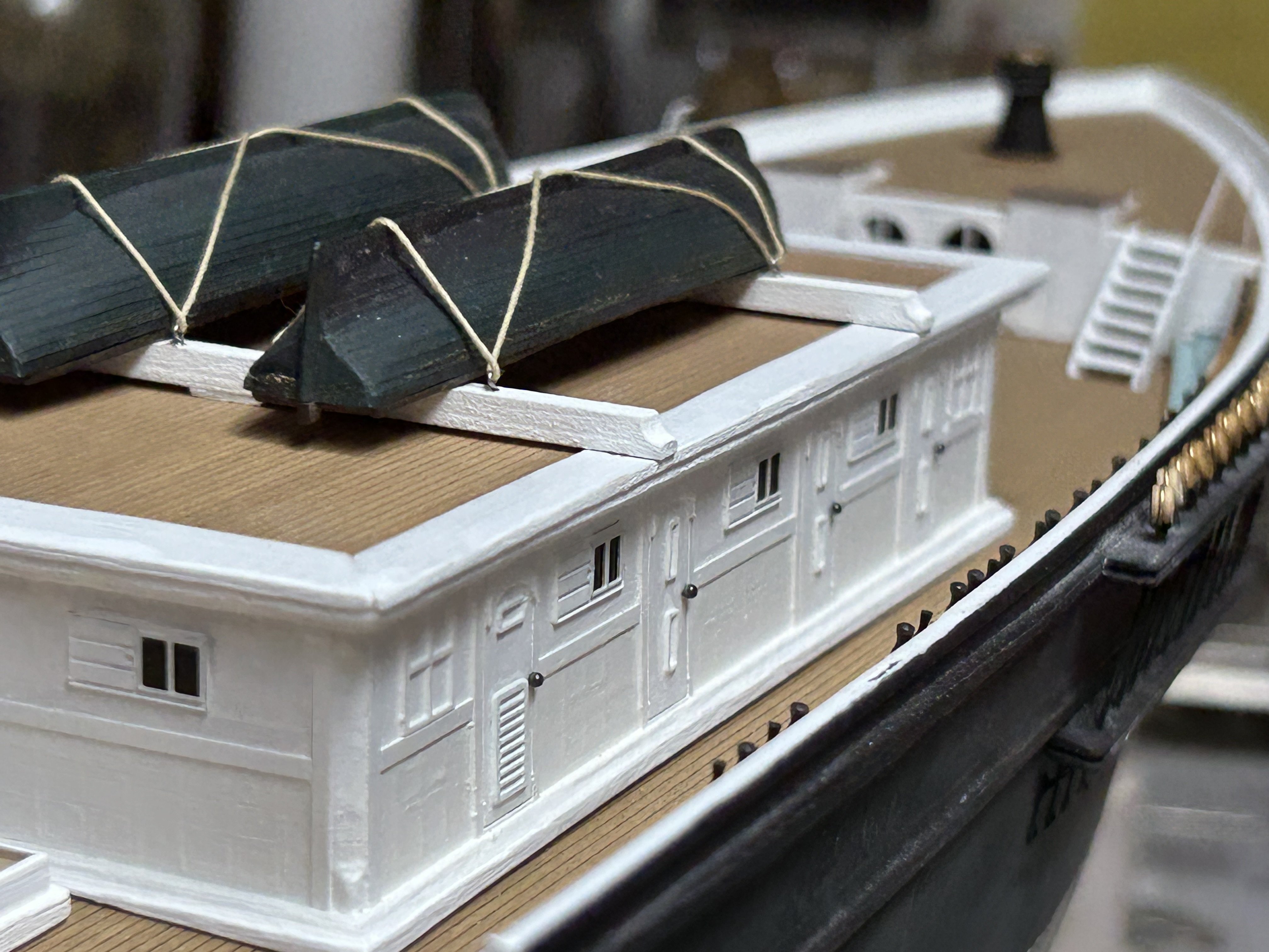
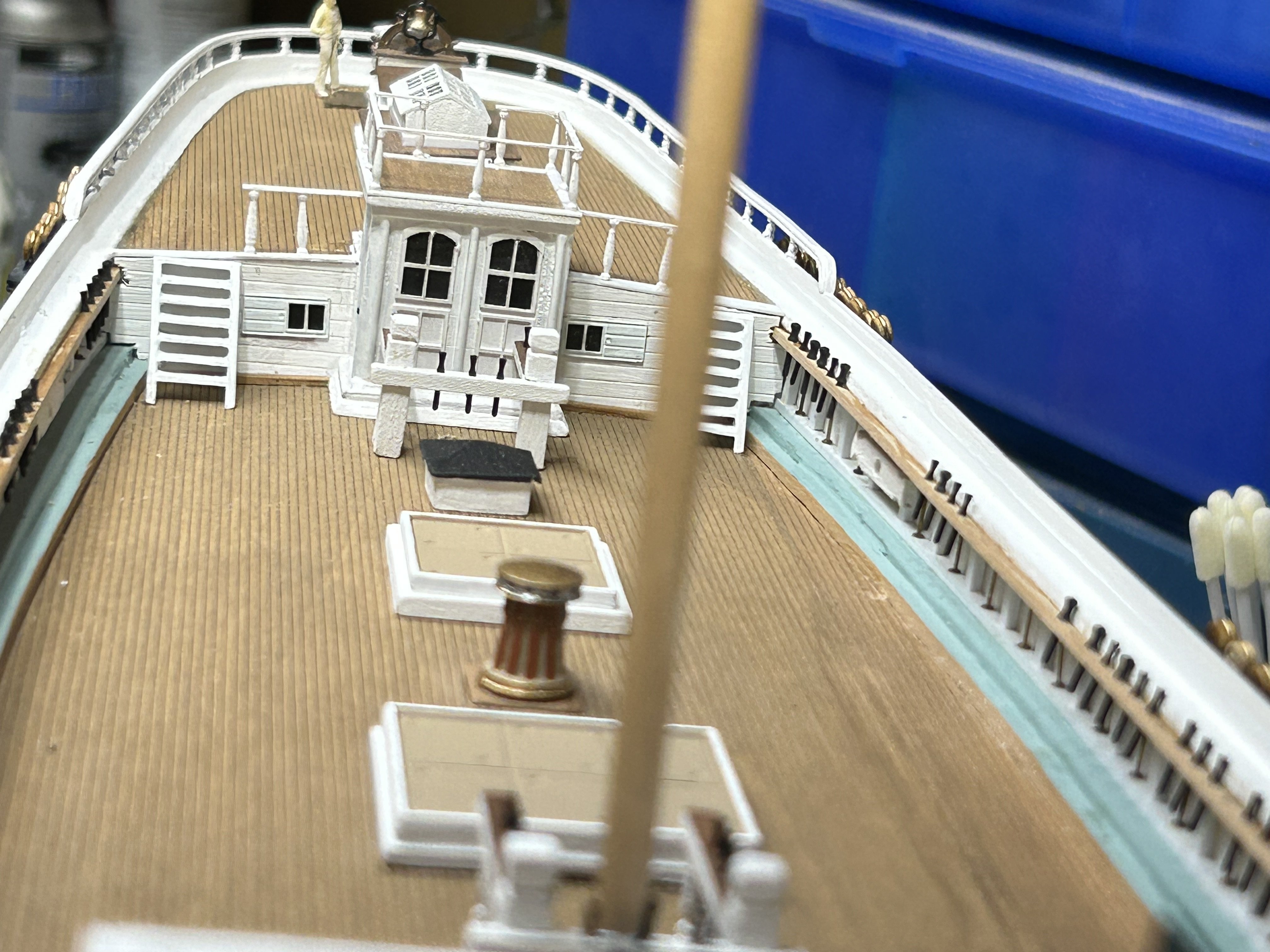
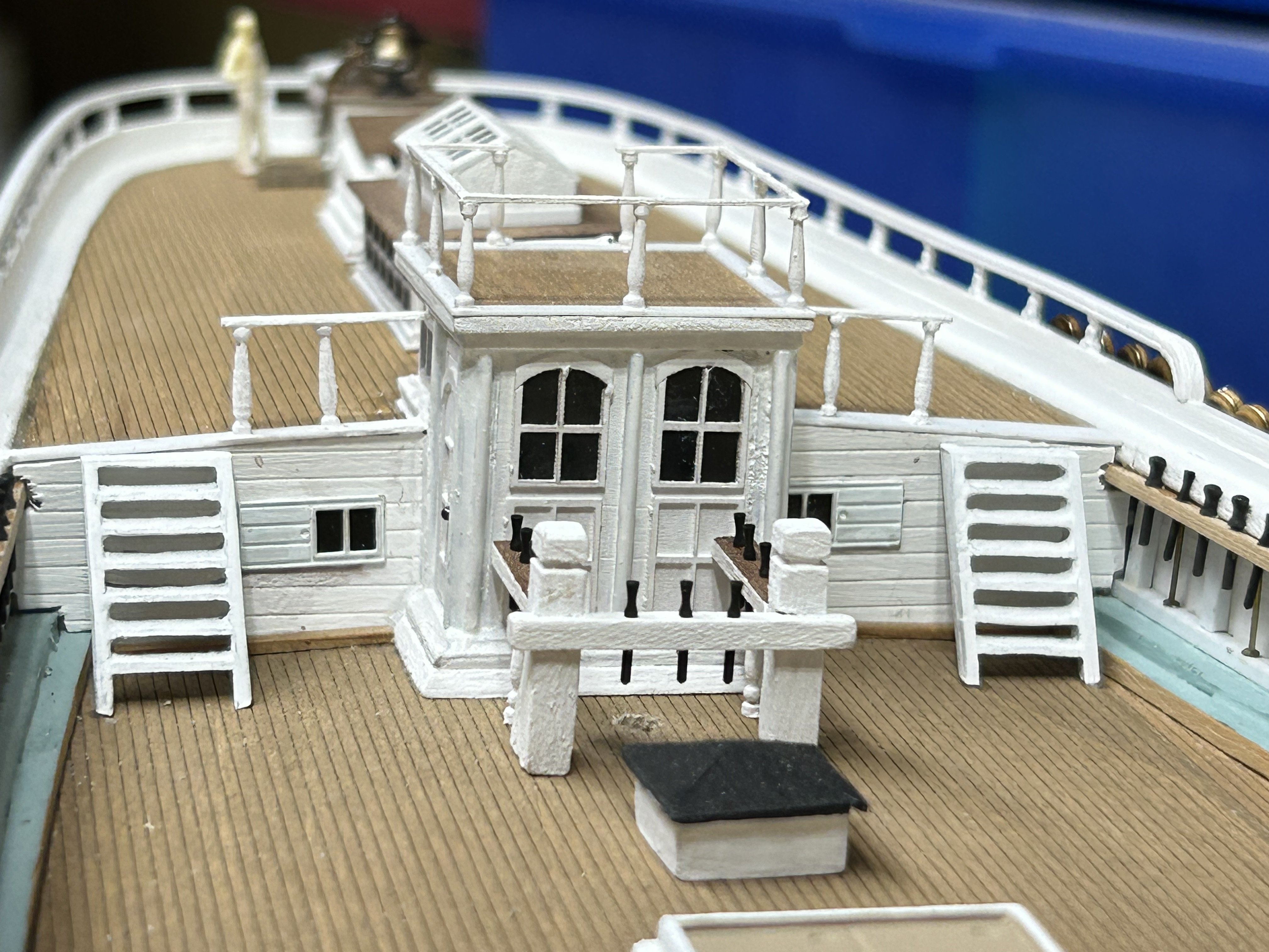
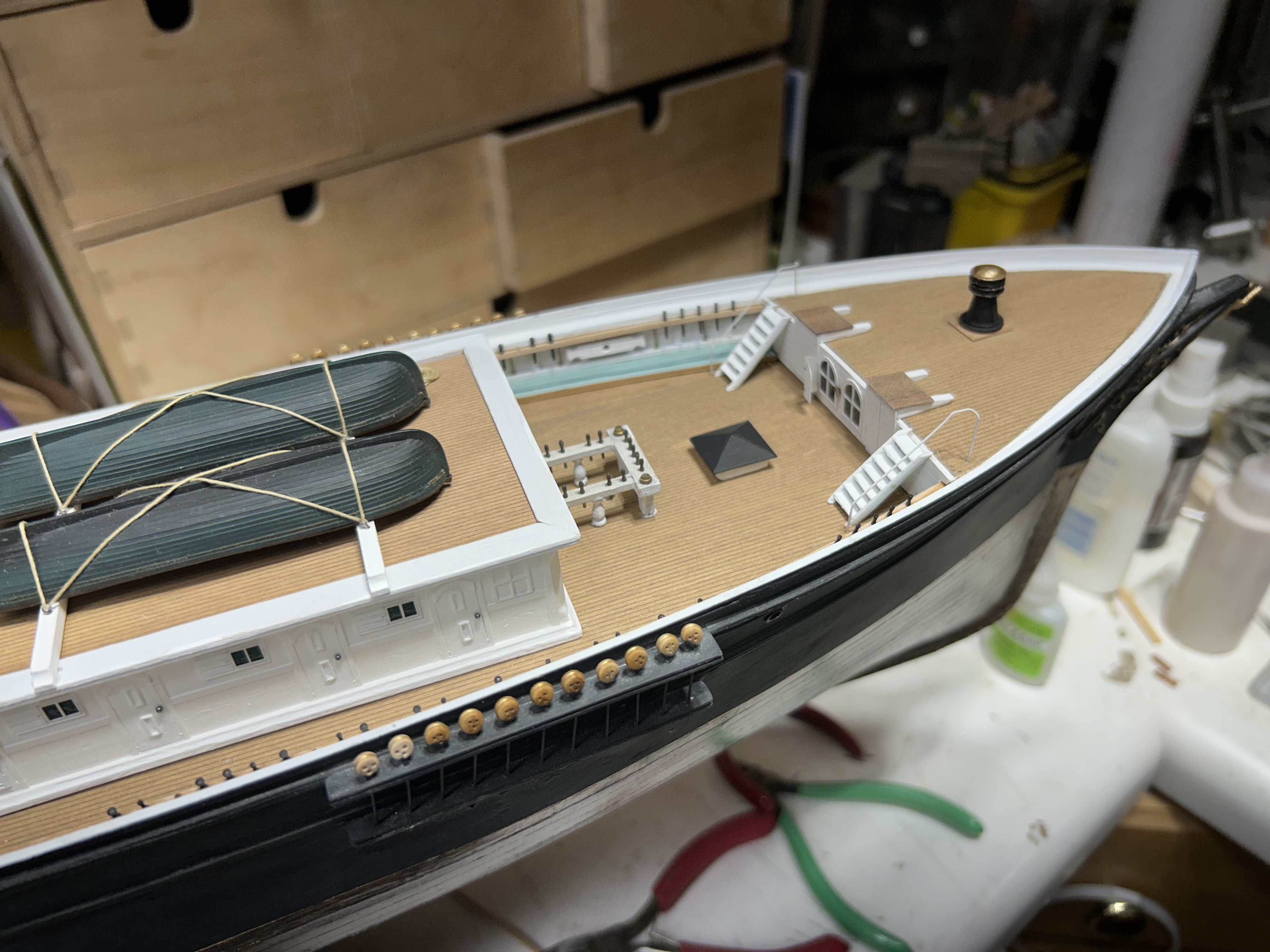
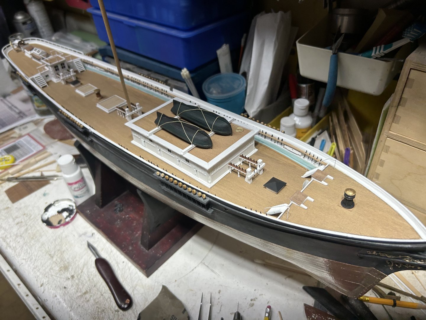
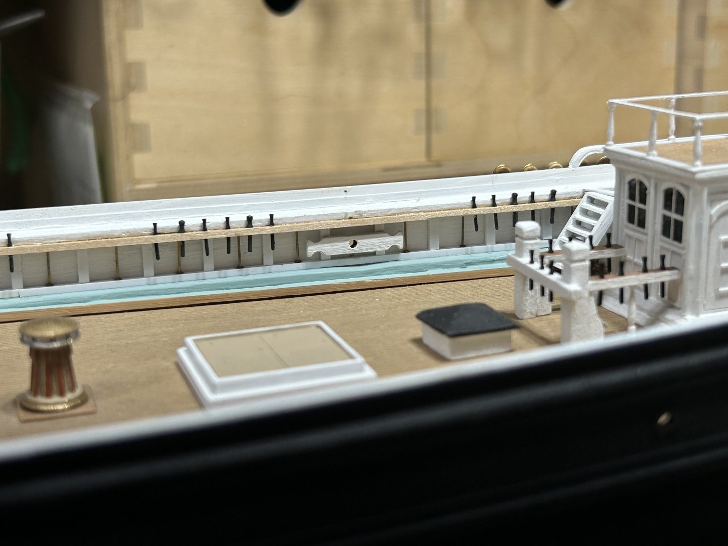
Took a few images around the model. Rob


-
Did a bit of work on the small details. Added forecastle step railing , the forward hold stair cover and began the fore fife rail. Rob


-
MikeR...Are you still working on the Flying Fish...Haven't seen any updates for quite some time. Rob
-
Some fantastic work. Very good metal work on the binnacle. Exceptional all around. Rob
-
Wonderful job...she is coming along nicely. The attention to detailing the yards out with *ALL* their blocks, stirrups foot ropes , flemishhorses, and sheet blocks can be daunting. Not to mention the jackstays. Many modelers tend to forego many of these and keep the yard furniture to a minimum. If you plan on adding leach and buntlines...you'll need these blocks as well. Not failing to mention those pesky jewel blocks for the reef tackle. It can get pretty busy for sure. Good luck. Will you be adding sails...furled or otherwise? Rob
- 200 replies
-
- 1
-

-
- Flying Cloud
- Mamoli
- (and 1 more)
-
This is exactly what I am saying when it comes to artist interpretation of other ships as well...such as the Great Republic...which has been poorly represented with incurring features from her original configuration and those of her rebuilt state. A whole lot of Mixin and matchin...has taken place...and if you are not a student of her history, you can easily be fooled by what the artist has painted. This is evidence that even Buttersworth, had either bias or ignorance.....or is just being an ARTIST. Since Buttersworth has a proven history of making small errors. One must, as it has been pointed out......skillfully use all data points...preferably first hand accounts. Rob
-
Those are beautiful. typically...those were removed when at sea and preparing for battle. Some modelers retain the boarding ladders on their clippers...such as Flying Fish and Flying Cloud. However, these egress ladders were quickly removed when the ship set sail....and they surely were not present when the ship was encountering foul weather.....such as I will be depicting Staghound..(Mimicing Buttersworth's painting). Someday I wish to visit Mystic and then go see the Constitution myself. Rob
-
Thanks Peter...I must have read right past that..... I couldn't find it in the body of the conversation....and it was right in front of my face....all the time. After looking through your log, I quickly gathered it was larger than 1/96. The scale all my clippers are built in.....so I can manage the room they will take and scaling them together, for size comparison. Good job...bringing back an old classic. Indeed it must have been a lot more crafting.... Rob
-
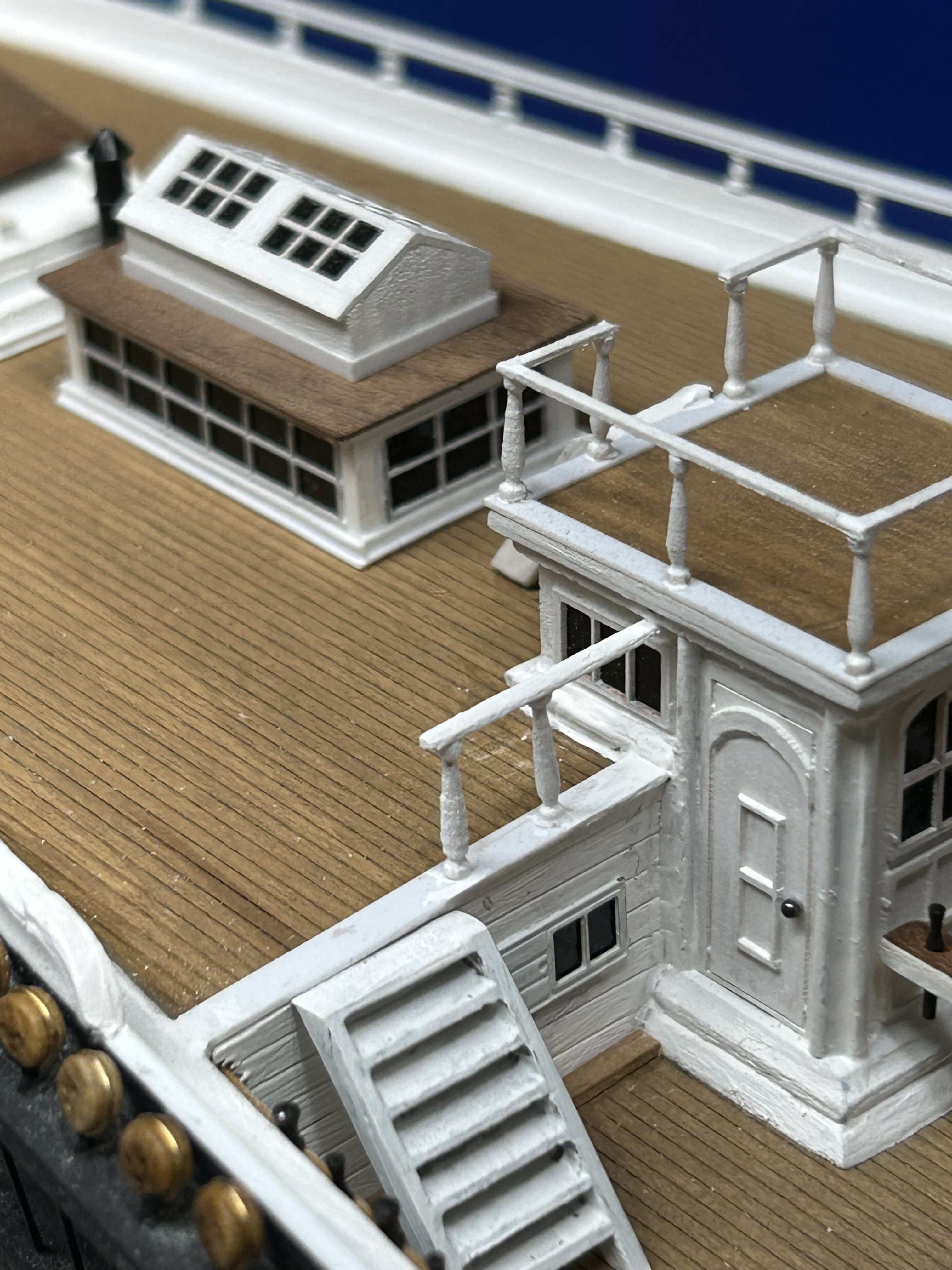
Added a few more details. Rob


-
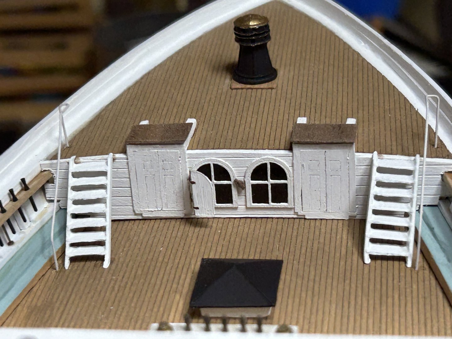
Finished adding the steps on the port side and finished the starboard side too. Rob
-
Peter......fine job for sure. I've looked...but what scale is that model in? Rob
-
Hoping you won't make a mistake....but those strakes at the stern go all the way back to the edge of the stern post...they do not curve as you have them against the last bulkhead. they should go straight back to the stern post. Rob
-
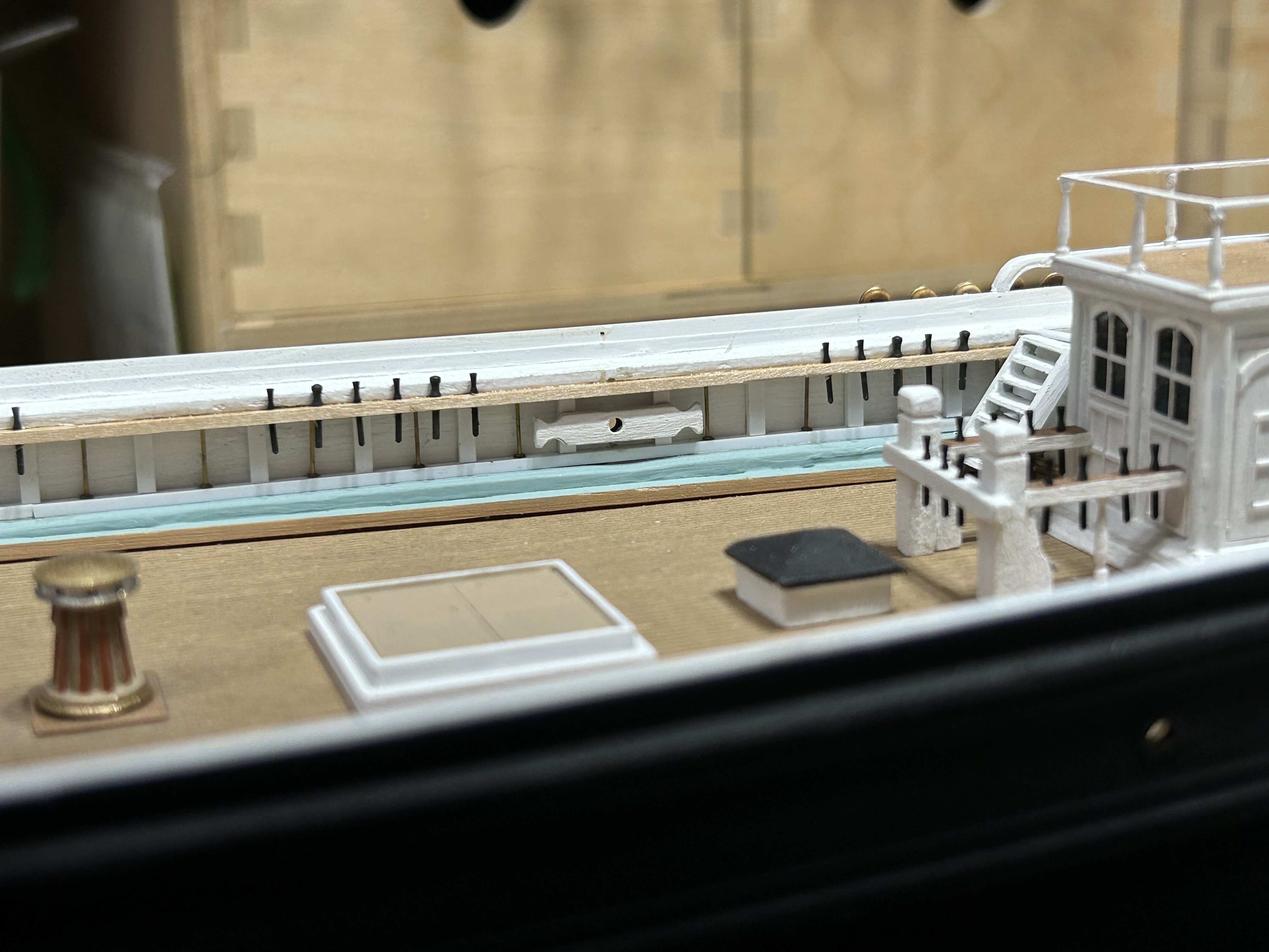
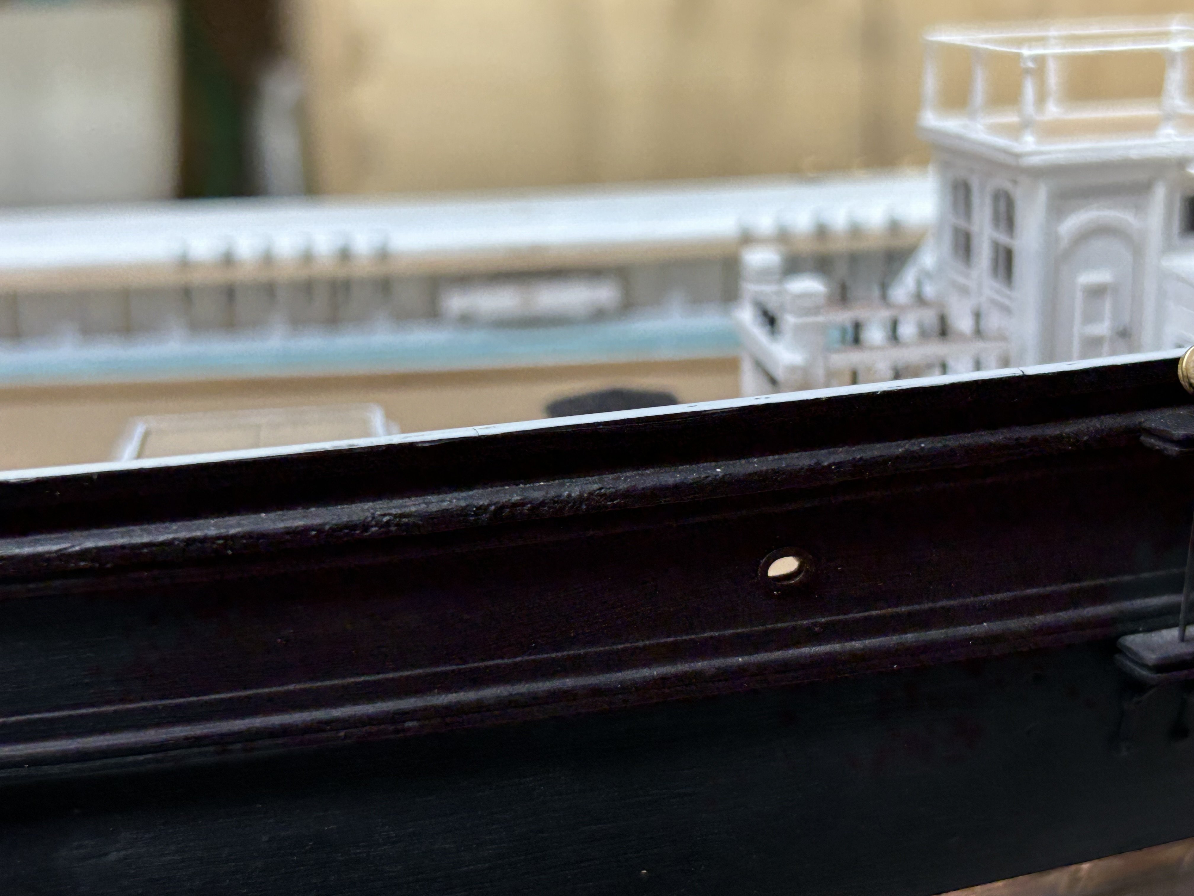
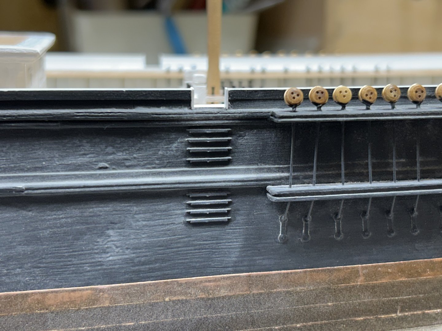
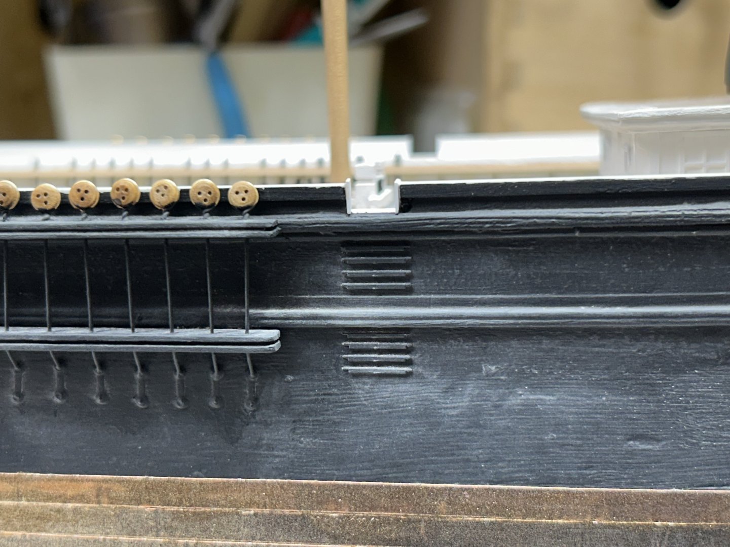
By the way Rich......what's up with that extended fantail railing on the Buttersworth painting? It extends all the way to the main channels. Now who is fudging the facts.....Buttersworth, or every other known drawing and painting of Staghound....? If there is a railing there...then that must mean, there is also decking there...if that is so....then somebody is in serious error, and her deck plan is not as we suspect. Duncan McLean's description and Cheppelle's drawings are in conflict with Buttersworth. Also note the impractical location of the midship mooring fairlead opening. It is right under the railing. If the fairlead is just at deck level...where the planksheer is...and the bulwark is roughly 6ft....why an additional 18" railing? And how is the fairlead even accessible if there is a deck over it? To many booboo's. Just sayin.... Rob
-
Thanks Rich. Moving slowly along the hull...adding details, I just decided it was next. Working from inside the hull I will drill the holes for the mooring fairleads...locating them, then finish up from the outside adding their sleaves. I then can place the cavils and bitts. Things have been a bit slow. I'm prepping to remove the veranda off of our front porch, because it leaks. That will be an all day, Saturday job. Repairing and reroofing the front porch, and rerailing the French doors. Our master bedroom has large French doors that go out onto the veranda. I have also been helping my wife remodel the bedroom...prior to this. Rob
-
Thanks Rick. Those steps are tiny little things. Rob
-
I did just a little today thus far. Added the port access way and steps. Not all of McKay ‘s ships had these access ways. Rob

-
Truly am sorry to hear about your wife and your vision issue. I thought kidney stones where trouble. I too have recently developed a floater in my left eye....causing some visual impairment...but not loss of vision. Age is having its way..I supose. The Admiralty model will be fun...no rigging to stress over and lots of detail remaining in the hull and armament to boot. Still waiting to see your model cased and mounted. It's been fun...and for you...quite some time too. I generally take 2~3 years to complete a scratch built model. Good luck with your next shipyard adventure. Rob
-
Well....there you go. A very fine model...well executed and clean. You've done a great job Jared. Congrats. How long has it been? Anything new on your horizon? Rob
- 431 replies
-
- 1
-

-
- Flying Fish
- Model Shipways
- (and 2 more)
-
Not quite sure Rich. Well everyone, I’ll be out of town till Monday. So no updates. Rob
-
That's sweet. My case for my Great Republic was made with maple and glass....and as you pointed out...weighs a ton. My Glory of the Seas case is only 3 sided plexi. Way easier and lighter. I'd like to find a place close by me who can make a large 5 sided acrylic case for my Staghound. Good idea......I'll look around. Can't wait to see your model mounted and displayed. Rob
- 431 replies
-
- 1
-
-
- Flying Fish
- Model Shipways
- (and 2 more)
-
Jared....she looks wonderful. Adding those belayed/coiled ropes will add conversational detail as well. I was thinking about an acrylic case for Staghound. Are you having that made locally, or sending out for one? Is it affordable? Rob