
MORE HANDBOOKS ARE ON THEIR WAY! We will let you know when they get here.
×

leclaire
-
Posts
115 -
Joined
-
Last visited
Reputation Activity
-

 leclaire got a reaction from FriedClams in USS Cairo 1862 by MPB521 – FINISHED - Scale 1:48 - American Civil War Ironclad - First Scratch Build
A question Brian - how did you cut the slot in the toothpick to insert the paddle blade. Something that small would be a huge problem for my shaky hands.
Bob
-
 leclaire reacted to Maury S in Byrnes saw extension….
Just build a small bench to set behind the saw. I'm constantly tipping my saw on edge to change blades. I don't need more stuff attached to the unit.
Maury
-
 leclaire got a reaction from mtaylor in Photographing your models
Hi Pat,
Lighting issues aside, your model looks pretty darn good.
Bob
-
 leclaire reacted to bruce d in Tools described
PILLAR DRILL : A tall upright machine useful for suddenly snatching flat metal bar out of your hands so that it smacks you in the chest and flings your beer across the room, denting the freshly-painted project which you had carefully set in the corner where nothing could get to it.
WIRE WHEEL : Cleans paint off bolts and then throws them somewhere under the workbench with the speed of light. Also removes fingerprints and hard-earned calluses from fingers in about the time it takes you to say, 'Oh sh*t'
PLIERS : Used to round off bolt heads. Sometimes used in the creation of blood-blisters.
BELT SANDER : An electric sanding tool commonly used to convert minor touch-up jobs into major refinishing jobs.
HACKSAW : One of a family of cutting tools built on the Ouija board principle... It transforms human energy into a crooked, unpredictable motion, and the more you attempt to influence its course, the more dismal your future becomes.
MOLE GRIPS : Generally used after pliers to completely round off bolt heads. If nothing else is available, they can also be used to transfer intense welding heat to the palm of your hand.
OXYACETYLENE TORCH : Used almost entirely for setting on fire various flammable objects in your workshop. Also handy for igniting the grease inside the wheel hub out of which you want to remove a bearing race..
HYDRAULIC JACK : Used for lowering a car to the ground after you have installed your new brake shoes, trapping the jack handle firmly under the bumper.
BAND SAW : A large stationary power saw primarily used by most people to cut good metal sheet into smaller pieces that more easily fit into the bin after you cut on the inside of the line instead of the outside edge.
TWO-TON ENGINE HOIST : A tool for testing the maximum tensile strength of everything you forgot to disconnect.
PHILLIPS SCREWDRIVER : Normally used to stab the vacuum seals under lids or for opening old-style paper-and-tin oil cans and splashing oil on your shirt; but can also be used, as the name implies, to butcher Phillips screw heads.
STRAIGHT SCREWDRIVER : A tool for opening paint cans. Sometimes used to convert common slotted screws into non-removable screws and butchering your palms.
PRY BAR: See Screwdriver
HAMMER : Originally employed as a weapon of war, the hammer nowadays is used as a kind of divining rod to locate the most expensive parts adjacent to the object we are trying to hit.
STANLEY KNIFE : Used to open and slice through the contents of parcels delivered to your front door; works particularly well on contents such as seats, vinyl records, liquids in plastic bottles and rubber or plastic parts. Especially useful for slicing work clothes, but only while in use.
ADJUSTABLE SPANNER aka "Another hammer", aka "the Swedish Nut Lathe", aka "Crescent Wrench". Commonly used as one size fits all, usually results in rounding off nut heads before the use of pliers. Will randomly adjust size between bolts, resulting in injury ,swearing and multiple threats to any inanimate objects within the immediate vicinity.
BASTARD TOOL : Any handy tool that you grab and throw across the garage while yelling BASTARD at the top of your voice . It is also, most often, the next tool that you will need.
-
leclaire reacted to mtaylor in Harold Hahn method
There's been several builds using the Hahn method. As for the scantlings... I don't think so. For the most part, those of us who did a Hahn build used his plans with minor mods as needed.
I really don't see a problem doing one using the scantlings and the Hahn method. His method was introduced to help make things "easier" for model builders, not to dictate style.
-
leclaire reacted to LJP in Thistle 1894 by LJP – FINISHED - 1:64 scale – a Wisconsin sternwheeler by Lawrence Paplham
Thanks Jim! Brian welcome aboard!
The Oxide Red turned out much darker than I anticipated. It hides a lot of the hatch details. I added a stained and roughed up rubbing strake. One Thistle photo showed a second, much shorter strake on top of that strake. Since this did not seem common, I omitted the second rubbing strake.
I will begin making machinery before I start the structures. I will need the two Scotch marine boilers, boiler and auxiliary feed pumps, two hand pumps. a dynamo and two poppet engines. I will probably do the pitmans and paddle wheel later, although I already have made the pillow blocks.
LJP
-
leclaire reacted to LJP in Thistle 1894 by LJP – FINISHED - 1:64 scale – a Wisconsin sternwheeler by Lawrence Paplham
Hi All,
The main deck planking is done, now is time to paint the deck oxide red. The bow still needs two hawse holes for the anchor chains as Thistle had bent arm kedge anchors. I did put a hatch there for access to the suspected chain locker/collision bulkhead. When Thistle had one of its literal run-ins with a rock that punched a hole in its bow, it was noted that the forward compartment filled but water did not reach the coal bunkers.
I also need two hog chain holes. In addition to the normal hog chains, Thistle had hog chains that seemed to run from the front of the boilers, through cutouts in the boiler room doors, and then into the hull by the main stairway.
Here is the planked main deck. The two oblong metal hatches in front of the boiler pit are the coal chutes, just like on the Paul L. . I also included two main hatches. Lastly, I put a hatch in the engine room, not unlike the S. S. Moyie. These latter three hatches, along with the one for the chain locker, are a best guess on my part as I have no Thistle photos to confirm what and where the hatches actually were.
-
leclaire reacted to mbp521 in USS Cairo 1862 by MPB521 – FINISHED - Scale 1:48 - American Civil War Ironclad - First Scratch Build
Thank you Keith.
That is a great question. From my research and reading, Cairo saw a lot of action in her one year of existence, but she also had a good bit of downtime. From the time Cdr. Selfridge took command of her though, she was on constant patrol until her sinking, so there is not much telling how much time they had to really square her away. Since the only known photo of her is the one that was taken shortly after she was launched, it would be next to impossible to tell what she looked like right before she went down. My best guess is that since the build of these boats was rushed, not a lot of time was given to her paint. Touchups could have been done during the couple of refits Cairo went through (additional railroad irons added to the forward casemates and the upgrades to the pilot house) but would she have had a fresh coat of paint added? No telling.
I want to try and add a bit of weathering to her without looking like she just slid down the ways, but not so much as for her to look like she's been on patrol for several years. I figured that she would have a bit of river grime on her from cannon ball splashes during her skirmishes and possibly a few battle scars, but not too much more. Some of the details of the weathering shown previously will be muted a bit, once I "fix" the pastels. I am still experimenting, so we'll see what comes out.
-Brian
-
leclaire reacted to LJP in Thistle 1894 by LJP – FINISHED - 1:64 scale – a Wisconsin sternwheeler by Lawrence Paplham
Hi Kurt,
Thanks for the quick heads up on the Badger Anti-Fouling Red Oxide. The colour I have is Model Expo's Hull Red. If you can believe the laptop colours when you Google your Badger or Floquil paints, the Model Expo seems close to your Badger Oxide Red. The Floquil seems a bit more brown but the swatch was very small and came from a colour chart.
Your comments on steamboats and barns is really helpful. I have no experience with steamboats but do have lots of Wisconsin experience with barns - having painted my uncles barns red in my very young years. My memories may not be that accurate anymore but I want to say that barn red was not unlike railroad boxcar red.
LJP
-
leclaire reacted to Cathead in Thistle 1894 by LJP – FINISHED - 1:64 scale – a Wisconsin sternwheeler by Lawrence Paplham
So often, in steamboats, the rule is "anything reasonable was probably done somewhere" (and sometimes unreasonable). I agree that the boiler and hurricane decks look like they have canvas, and it seems more likely that those weren't painted red, so a natural canvas color would seem appropriate there? With a dull red for the main deck as a contrast? In the absence of better evidence I'd say choose what looks attractive to you personally and what you can reasonably justify.
-
leclaire reacted to mbp521 in USS Cairo 1862 by MPB521 – FINISHED - Scale 1:48 - American Civil War Ironclad - First Scratch Build
Hello again everyone,
Time again for another update. With the summer winding down and the weather cooling off, I have been busy with my "Honey Do" list but managed to find some time to put together a few more items on my build.
I finally finished getting all of the remaining cannons installed and rigged. The three forward cannons are complete with the exception of the rope coils. I managed to run out of rope with only a couple of feet needed to finish, but more is on the way.
Picture of one of the forward 42 pounders rigged and ready for install.
One of the starboard side 8" Smoothbores in place.
Here are a few pictures of the gundeck at eye-level showing powder barrels, munitions crates and the crews mess lockers.
Next I worked on the hog chains. For these I used brass wire for the chains themselves, styrene for the turnbuckles and copper sheeting for the cast caps.
Up close picture of the actual hog chains. These took a little bit to figure out exactly how they were built. I had a few personal pictures from my last visit in 2014, but none with any real detail. I did try looking up some others on the internet, but the hog chains don't really seem to be an area of focus for visitors so the pictures are limited to long distance shots that I had to zoom way in on. Nevertheless, I think my interpretation of them is fairly close.
Here is the horizontal chain with the ends formed into the eyes.
Then it was time to test my metal working skills to see if I could solder the eyes to close them up without making a mess of things. Well, almost. Nothing a little drilling and filing can't fix.
There we go. They look a little better cleaned up.
Now to get them bent into shape. The forward chains are significantly shorter than the aft ones, due to their placement, so the angle on them was a bit more. Also, where the hog chains rest on the posts the iron was pounded flat to give it a better mounting surface. The green area drawn on the wire is where I flattened the brass to rest on the caps.
Both horizontal chains shaped and flattened.
Next came the cast caps. These were made from thin copper sheeting that I cut to size and scored along the folding edges to get the correct shape.
Then they were placed on the hog chain posts and glued to the horizontal chains.
From the pictures that I was able to find and zoom in on, it is difficult to tell if there were bolts that were inserted through the chains and cast caps into the tops of the posts. It would make sense for them to put something there to avoid the chains from slipping off, but since I was not able to find any pictures of the tops of the posts, I took my builders liberties and drilled them out and will place bolts in them.
Next work was done on the turnbuckles. Or at least that is what I think these are called. They are not built like regular turnbuckles but they look to function as a way to tighten the tension on the hog chains. These were built with the same brass wire and styrene plastic.
Partially assembled.
and temporarily installed.
Port side.
Starboard side.
Before I got too far ahead of myself, I remembered that I had not built the axle pillow block caps. So I figured that I had better get to these before they were buried and impossible to install. These I just carved out of a piece of square stock and sanded to shape.
Cut out and just needing a little finish sanding.
Sanded and painted. I use the gold beads to simulate the grease cups. With the small nail in the top, I think they look pretty convincing.
And all mounted in place.
Next came work on the pilot house. I was not actually ready for this part, but I was running some additional lights before I closed up the boiler for good (I ran all of my wiring to terminate under the boiler) and had the thought that it would be neat to put some LED's in the pilot house to give it a little additional detail. So, I decided to go ahead and get it built.
So to give a brief history on the pilot house. The original plans for these was a wooden octagonal substructure, 12" thick with 1.5" thick iron plates fastened to the frames for protection. After several men on the Louisville and St. Louis were injured or killed by flying shards of iron from direct hits on the pilot house during Battle of Fort Donelson, including Flag Officer Foote, Lieutenant Bryant (then commander of the Cairo) had some modifications done to the pilot house in order protect the crew from further injury.
While Cairo was awaiting her next assignment, Lt. Bryant put her crew to work extending the front three panels of the pilot house. They added an additional 7.5" of timber to each panel and then reinforced the inside of the house with pine paneling. Additionally, 1/2" thick iron flaps were added to the ports as well to protect the pilots form enemy sniper fire. When these ports were closed, the pilots would have to navigate by squinting through a peephole drilled into the flaps that was about the diameter of a silver dollar. All in all, these modifications gave the pilot house its new unique shape.
So I started out by tracing the footprint of the pilot house from the HSR plans. I drew the footprint up on some card stock to use as a mounting and construction base. I over extended the lines to give me a cutting line for the toe boards, then glued the strips down for the toe boards.
Once the boards were all in place I removed the excess card stock to start going vertical. Once I had this part cut out I realized that my octagon shape was not uniform and that the sides of the pilot house extension weren't even.
So I went to the computer and dug out my trusty Visio program to get a perfect Octagon shape. Then with careful measurement, I added the extension to the octagon then sized everything to scale. This is the new result. Much more uniform.
First course of toe boards in place.
Then it was on to building the sides.
Five sides up and rivets installed. I simulated the rivets the same way that I did for the casemate armor.
Extension sided in place. These were added when the front three panels were beefed up to compensate for the new thickness.
All eight (actually ten) panels in place and the structure temp installed in it's home.
Next it was time to install the view ports. To give them some depth, I built up some wooden tunnels to simulate the 19.5" walls.
Next I started constructing the top. This was pretty much the only part of Cairo that was left exposed from the Yazoo River mud, so it had long rotted away by the time the pilot house was recovered in 1960. Without knowing exactly how this part was constructed, I used what information was available on the HSR and what Bob Hill had drafted up, and made my own version.
My thoughts were that for the most part, since the top of the pilot house was flat one can assume that the roof was as well. The drawings show the center of the octagon to be open with a wire mesh covering the opening. I can somewhat see where this could be the case in that since there was a entry hatch from the gun deck with a ladder to access the pilot house just forward of the boilers and the cook stove. Given the hatch placement, you would think that some of the heat from below would filter up to the pilot house. That as well as the entire structure being painted black would make for an almost unbearably hot place to be on sunny days, so they would have to have some sort of ventilation besides the portals. However, with an open top, that exposes the pilot and controls to rain and other elements, so there could have possibly been a cover that could be placed over the opening. This cover could have just fit down inside of the opening with a small lip around the edge to hold it in place. Handles could have been mounted to the cover to facilitate removal and installation. Somewhat like a manhole cover. So this is what I came up with.
The basic shape of the top.
Cutting out the center opening. I'll use this part as the cover.
Installing the wire mesh. I don't think that this served much of a purpose in the way of protection from arms, but it could prevent tree branches and the occasional bird from coming into the pilot house.
Installation of the port flap hinges and flaps. These I just made with styrene rods and sheets. I used foil tape again for the rivets.
I wanted to show some of the ports closed, for the details and to give somewhat of a peak at the small aperture the pilots had to peer through when they were closed. This is also the area where I placed the lanterns to light things up inside.
For the pine paneling on the interior, I printed some lines on cardstock and glued this to the inside of the pilot house.
Lanterns installed. The extra cardstock under the lanterns is to cover the wiring. Very little of this will be seen, but I wanted to cover it up just in case the keen eye is able to spot it from the outside.
The completed structure temp installed.
Lastly was the construction of the access ladder.
This was another feature that was never recovered from the wreck and there is no mention of it in the HSR so I just went with a simple build of a round rung ladder that would allow the pilot access to his house.
Placed near it's location in relation to the hatch that will be built when the hurricane deck goes in.
Finally, I started work on the lifeboats. The City Class Ironclads each carried four of these. Unfortunately none of the ones from the Cairo are around anymore and it is hard to say if any were deployed during her sinking since she went down in 12 minutes. From my reading on the sinking, Commander Selfridge ran her ashore as soon as she was hit, where most of the men jumped from the boat and swam or simply jumped to the ground before she slipped off the bank and went under. It is most likely that the lifeboats broke loose over time and drifted downriver in the swift Yazoo River current or they simply rotted away in the their davits.
So since there were no surviving lifeboats to model them after, I relied on pictures of the Cairo as well as the other boats for the details. From the available pictures they look to be pretty standard in shape with a flat transom and from the measurements on the plans they are about 6.25" which scaled out at 1:48 would be about 25' long. Rather than scratch build four of these and run the risk of them all not coming out shaped the same, I cheated a bit and bought some Model Shipways kits instead. There was only one problem with this, the biggest MS kit is only 5.25" long. So I kit bashed the lifeboats and extended them the extra inch. For the most part I got the desired shape and length I was looking for.
Stretching the keel.
Keel stretched.
Planking going on.
And the finished result.
I then gave it a shot of black paint and started to other three. I'll get them all built and painted before I build the interiors of them. I still haven't decided if I am going to cover them with tarps or not. I am still researching the techniques on how to simulate them and need to practice up since I've never done that before. I'll at least leave one uncovered to see the benches, oars and other details, just don't know about the rest. Once I have all four completed, I'll post more pictures.
Well, that is all for this update. Hope you all enjoyed it. Thank you all again for the likes, comments and just stopping by.
Until next time, take care and be safe.
-Brian
-
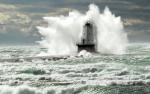
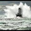
leclaire reacted to Chuck Seiler in The Pilgram - Tall Ship - sinks at its berth!
Is that the origin of "Doing a half fast job"? 😁 (Think about it.)
-
leclaire reacted to Canute in USS Cairo 1862 by MPB521 – FINISHED - Scale 1:48 - American Civil War Ironclad - First Scratch Build
You might want to looks at Pan Pastels here: https://panpastel.com/products.html
They have an extensive palette and are easy to apply. Work on some practice pieces before you do Cairo to get a feel for applying these pastels. I like them, because you can top coat and the colors and distribution won't change. Almost like there is a glue involved.
-
leclaire reacted to BANYAN in River Boat Wreck in North Dakota Found
Thanks for sharing Mark; possibly one of the very few good things to come from a drought. Hopefully, someone will record it.
cheers
Pat
-
leclaire reacted to mtaylor in River Boat Wreck in North Dakota Found
https://www.cbsnews.com/news/north-dakota-drought-exposes-130-year-old-shipwreck-abner-oneal/
-
leclaire reacted to LJP in Thistle 1894 by LJP – FINISHED - 1:64 scale – a Wisconsin sternwheeler by Lawrence Paplham
Hi Bob!
Never thought of Michigan State colours! My red will not be Bucky Badger Red but a dark oxide red like a hull red so the people in Madison will still not approve. LOL
Cathead,
Here is the best Paul L. photo postcard that I own for deciding to use canvas on the boiler deck. You can definitely see the deck planks on the main deck, but the boiler deck - especially around the stacks and by the railings - looks just like the covered hurricane deck. The other issue is what colour the boiler and hurricane decks should be. I know the article referred to the "decks", as in plural, being red, but everything I have seen and read seems to point to a grey colour and not red. Again, any input would be greatly appreciated.
Hi Keith! Welcome aboard! Hope you find this interesting.
I am still working on planking the main deck. I have mocked up some Scotch Marine boilers and finished off the boiler pit, since Thistle's boilers were located within the hull and not on the main deck. I need to make certain the stacks line up through the boiler deck. I have struggled somewhat in portraying the coal in the bunkers but I think I have a reasonable approximation. I do not have the measurements of any of the boilers used in Thistle. Similar Ryan built boats did have two 4' by 12' boilers, so that is what I am using. [The Paul L. had a single 9' diameter boiler that was described as the largest Ryan installed boiler at the time.] In a really odd twist, a boiler from when Thistle was scrapped ended up in an Oshkosh school. There was a real bad newspaper photograph of that boiler when the school was demolished in the 1960s. I would loved to have had a clear and usable photo.
The decking will take a few weeks as I attend to family duties.
-
leclaire got a reaction from mtaylor in Thistle 1894 by LJP – FINISHED - 1:64 scale – a Wisconsin sternwheeler by Lawrence Paplham
I don't know, that paint scheme so far looks like Michigan State Spartan green and white. You may have some explaining to do to the folks in Madison. 😜
All kidding aside, very nice indeed.
Bob
-
leclaire reacted to LJP in Thistle 1894 by LJP – FINISHED - 1:64 scale – a Wisconsin sternwheeler by Lawrence Paplham
Over its 21-year lifespan, Thistle had numerous paint schemes. Unfortunately, black and white photos, “colorized” postcards of dubious accuracy and generalizations of “light colors” help little in arriving at accurate paint schemes.
Luckily, the May 6, 1907 Oshkosh Daily Northwestern newspaper (via Newspapers.com) presented that:
” decks being colored red, the hull in sea green, the cabins in grey and the rails and stairways in white.” By that time, the hull below the waterline was covered with two coats of boiled linseed oil instead of paint. This will be my paint scheme for Thistle.
On how paint was made, according to Donald Jackson in his Voyages of the Steamboat Yellow Stone [Ticknor & Fields, 1985]
“Because all paints were mixed on the job by adding various pigments to white lead or linseed oil, the order called for lampblack, bluish-green verdigris (a copper compound), red litharge (a lead compound), yellow ochre, copal and Japan varnishes, and, of course, turpentine in large quantities.” For my model, the sea green that was used is comparable to the sea green used in the pilothouse of S. S. Moyie. The grey will be comparable to the original grey paint on the Steamboat House at Marble Park in Winneconne, Wisconsin. The red will be a darkened red more period specific than the bright reds now seen on current sternwheelers. Boiled linseed oil was used on the hull below the waterline. Interior main deck colors will be white upper and a yellow lower. The yellow will be comparable to the yellow on steamboat relics in the Steamboat Graveyard across from Dawson City.
Thistle was described as having between 3 to 3 ½ feet of draft. There is a side profile of Paul L. at the Oshkosh Public Museum site that shows what the bottom and sides of Paul L. looked like. I would expect that Thistle would have looked much the same. Note the photo of the Paul L. was from after the May 1910 capsizing as there are now straight stacks unlike the earlier “Thistle Like” stacks that had rings at the top of the stacks. The link, if you should so desire:
Steamboat Paul L. - P1182.119 (pastperfectonline.com)
I gave the bottom of Thistle’s hull the historical description of two coats of boiled linseed oil and nothing else. This looks like uncolored varnish. The photo of the Paul L. shows a much darker bottom. By that time Paul L. would have been in service nearly three years and the bottom would have been much dirtier. I suppose that I could have aged Thistle’s bottom to reflect that aging.
The sides, the guards and the rudders were spray painted Ocean Green. The underside of the main deck planks over the guards will be this same color. I was not concerned about the overspray as the deck planks will cover this. There are colorized postcards of Thistle that show green bottom or sides that are close to that ocean green. Again, artistic license may have impacted the colors chosen on the postcards.
This is what the model looked like after the hull was painted. I was uncertain about the cylinder timbers so I painted them white.
There is always a discussion of tarpaper or canvas on decks. The birds eye photos of Thistle and Paul L. provide no clarity as to which was used. There are photos of Yukon steamboats where canvas was being laid. The S. S. Moyie described where canvas would last about five years on the decks, and several layers were present on the decks when the boat was renovated. Canvas was used on Thistle on the main deck above the bulwarks for shading so it was already in use on the boat. “Canvas, painted and sanded” will be used instead of tarpaper.
I know that a covering was used on the hurricane deck based upon both Thistle and Paul L. photo postcards. In the capsized Paul L. photo postcards, the main deck was left uncovered. The Paul L. boiler deck seemed to have been covered. The much smaller boiler deck was also covered on Moyie.
I would appreciate input from others on whether the boiler deck should have been covered or not. I know most models show this of not being covered so if I were to cover the boiler deck that would be a huge departure from the norm. I am trying to get more photos of the capsized Paul L. to try and provide more clarity.
The main deck is next up. This will take some time.
-
leclaire reacted to LJP in Thistle 1894 by LJP – FINISHED - 1:64 scale – a Wisconsin sternwheeler by Lawrence Paplham
To create the guards, I used the photos from the capsized Paul L. The outrakers were placed at a scale 22 inches on center. I created a jig, which is seen in the bottom center of the photo below, to be consistent in placing the distances. The outside planks (no idea what these were called) were affixed to the underside of the outrakers and the inner rubbing strake. The cylinder timbers had to be added at this point to complete the guards. I always tried to think several steps ahead in order to prevent rework or creating much more difficult processes. I was not always successful in this endeavour.
This is a shot of the work in process.
This is what the final result looked like.
The two balanced rudders replicated what was on the Oshkosh Museum stern photos.
This is where I had one of my “should have thought farther ahead” moments. The transom needed have a section removed between the cylinder timbers to accommodate the eventual pitmans. And the transom needed to have a section removed between the rudder stops for the rudder tillers. I chose to have the tillers beneath the main deck. I had seen some sternwheelers that had the tillers on the main deck (which used up a lot of usable deck space) or placed under the boiler deck. In this latter case the rudder post had to extend up between the transom and the false transom. This method affected the main deck if it extended beyond the transom to the false transom.
This is a photo of the rudders and rudder stops before: final finishing, being secured, gudgeons & pintels added, or painting. I had also drawn a temporary waterline
I now need to paint the hull before starting on the decking and stationaires.
-
leclaire reacted to wefalck in USS Cairo 1862 by MPB521 – FINISHED - Scale 1:48 - American Civil War Ironclad - First Scratch Build
Nuclear submarines are steamboats (with a low carbon footprint) after all
-
leclaire reacted to LJP in Thistle 1894 by LJP – FINISHED - 1:64 scale – a Wisconsin sternwheeler by Lawrence Paplham
I had not planked a hull in a long time and it showed.
Unlike Chaperon, Bertrand and others that had bottom planks that were flat, Thistle had planks that bent at the stem and stern, not unlike a clipper ship. Thistle did have bottom planks that were considerably wider than the side planks as noted in the Paul L photos. Thistle’s actual bottom planks were made of oak, and the side planks of Eastern white pine. Paul Ls. bottom planks were made of Cyprus and the side planks Douglas fir. Keels of both were local oak. The 1894 Thistle was able to use local wood but the supply was depleted by the time of the 1907 Paul L.
Initially, I tried just tapering the planks. Huge mistake. I removed the mistake and decided to do it the correct way with spiling the planks. I referred to Model Ship World articles on the process and consulted a 1980s vintage book that I owned on planking.
I used poster board to create the templates for each row of planks. That was much easier to bend and trim than the actual basswood planks. One template could be used for both the port and starboard side. It was heartening to discover that my hull was symmetrical. The wood planks still required beveling the edges and bending.
My keel frame did not have the stem post attached. Instead of cutting in the rabbits, I ran a 1/16 square stock from stem to stern on the keel frame. The planks then abutted this. The frame at the stem was tapered to meet the 1/16 square stock and the ends of the planks tapered to meet the square stock. After the hull was planked, I ran wider stock over the smaller square stock on the bottom to portray the keel that Thistle had. A stem post was added. The stern had a curved stock to follow the spoon shaped stern.
In this photo, I had just started the correct planking process. Note the line demarcations on the frames where the individual planks were to be affixed. I started with few planks by the sheer strakes to add stability. I then went down to the keel and garboard strake and planked from there up.
The second product looked much better than the first try.
Off to building the guards and rudders.
-
leclaire reacted to LJP in Thistle 1894 by LJP – FINISHED - 1:64 scale – a Wisconsin sternwheeler by Lawrence Paplham
Hi Bob & Roger!
I am back.
I really struggled with the hull.
I also have an admission: the planked hull is complete and I am currently working on the guards and rudders. I will go through my process, my mistakes and reworks. I wanted a complete hull before I started my post because I had no idea how long it was going to take or how many blind alleys I would follow. Both were time and mistakes were considerable.
Creating the hull for the Thistle included two main sources. The hull sheer came from Thistle photos. But I had no idea what the hull was like below the waterline. Instead, I used Paul L. photos as capsized to create the water and rib lines. Thistle and Paul L. had virtually identical hull dimensions, had the same builder (Ryan) and the same owner when the Paul L. was built (LeFevre).
There are several photos that I found the helpful in creating the hull.
This is the bow of the Paul L. while under construction. George Ryan is the man in the center. Note the massive stempost (Thistle’s was even larger), the bow frames were not canted, and beginning with the 7th frame, the frames are doubled up to the water line. This construction was typical for Ryan based upon accounts of other Ryan built boats. Reprinted with permission Neenah (Wisconsin) Historical Society.
A bow photo that shows the flat bottom, a true keel, rounded futtocks, and a sharp model bow. Reprinted with permission Neenah (Wisconsin) Historical Society. There are several other bow shots that I consulted during the build. I also own several postcards of the capsized Paul L.
There are two Paul L. stern photos from The Oshkosh (Wisconsin) Public Museum – the links are provided below. I was not timely in requesting permission to reprint here but the links will bring you to the low-resolution photos. Note the balanced rudder, the Ryan “spoon shaped stern” described in period articles, paddlewheel detail and other items. The museum has high quality digital jpg’s for purchase, which I did purchase. The enhanced digital photos are clear enough to permit the number of planks to be counted. This was incorporated into the model. You could also see many of the bolts which held the planks to the frames.
Steamboat "Paul L " Capsized - FP2003.20.734 (pastperfectonline.com)
Steamboat "Paul L " Capsized - P6767.2 (pastperfectonline.com)
Interestingly, the barged-out hull of the Paul L. lies under water in the Fox River between locks 2 & 3 in Appleton. It was dived on by scuba divers and a video created in about 1995. The green mossy hulk was interesting but not helpful in the build. A quarter century later I was not willing to have more scuba divers hopefully locate and once again dive on the wreck. The video, should you like review it, is located at: https://archive.org/details/WiscRiverboats
I consulted Bertrand’s lines to help me. John M. Sweeney’s contemporary River Practice of the West from the Transactions of American Society of Mechanical Engineers (Volume IX) provided lines and hull cross sections. Circa 1890’s, I am lucky enough to have an original copy of this. The Institute of Nautical Archeology has a whole series of Yukon sternwheeler articles. In many respects, Fox and Yukon boats were very similar.
My first step was to build a full-scale rough bulk head hull model using architectural foam and balsa. Many, many iterations and adjustments later, I sliced it into sections to create the frames. I decided to build a plank on bulkhead hull for the model instead of using actual individual frames like the real hull would have used. My generated frames did not line up with where the expected actual frames would have been. But I will be able to take the lines off of the plank on bulkhead hull should I decide to build another Ryan sternwheeler. But not now.
This is what the completed framing looks like. The open, boxed in area is for the boiler. Ryan used Scotch Marine boilers located within the hull instead of Western River boilers which were typically placed on the main deck. I tried using bulkheads with a cutout for the boiler but those were incredibly weak and I broke numerous ones before I used this box layout.
Photos of the hull of the Yukon sternwheeler Gleaner show how the supports for a boiler installed in a hull looked. You can find the Murray Lundberg photos posted at http://explorenorth.com/library/ships/bl-gleaner.htm
A bit of a diversion here. Gleaner’s machinery came from the Marine Iron Works of Chicago USA (MIWC). MIWC provided actual blueprints for building the sternwheeler when all the machinery was provided by them. So, the remains may be from a set of those blueprints – which I have been unable to locate. Alternatively, MIWC also provided a compete hull in knockdown form which was then sent to the owner along with the machinery and blueprints. The owner then reassembled the hull.
The next section will cover how I planked the hull.
-
 leclaire got a reaction from Canute in Thistle 1894 by LJP – FINISHED - 1:64 scale – a Wisconsin sternwheeler by Lawrence Paplham
I too just found your build log. Very much looking forward to following along as steamboats are a particular interest of mine.
Bob
-
leclaire reacted to mtaylor in USS Cairo 1862 by MPB521 – FINISHED - Scale 1:48 - American Civil War Ironclad - First Scratch Build
Interesting to say the least. You might be right about the shorter breaching rope. It wouldn't need to come back too far and the "training tackle" would be used to adjust the azimuth. A 30 to 32 pound shot wouldn't be a problem doing it that way although the gunners would be more exposed to small arms fire.
If it were one of the 75 (?) or 100 pounders that probably would be a problem. I'm trying to remember where I saw it but some of those vessels had "armored" hatches which were closed for loading. Could have been one of the builds here or maybe out at the Warfare History Network. It might have even been at Fort Donaldson (which I visited many times a few decades ago) as plunging fire did a lot of damage to the ironclads as they were armored on top.
-
leclaire reacted to mbp521 in USS Cairo 1862 by MPB521 – FINISHED - Scale 1:48 - American Civil War Ironclad - First Scratch Build
Don, Pat, Steven, Gary & Eric, Thank you so much for the kind comments. I appreciate your continued support.
Mark,
Thanks for the kind comment and not to worry about asking about the breech ropes, this is an interesting question which could possibly use some more discussion. While they do look like they are somewhat short, I based my rig on some of the research pictures that I found on how the 19th century naval guns were rigged. Most of the ones that I found show breech ropes that look like they barely allow for clearance to reload after recoil, most of these navy ships had almost vertical gun ports. Since the gun ports on these Iron Clads were sloped at 35° angles (port and starboard sides) & 45° angles (fore and aft sides), I would guess that this drastically reduced the amount of clearance for reloading. I'm wondering if the breach ropes were just used to keep the guns from recoiling too far back given the limited space on the gun deck and were only used to keep most of the strain off the smaller ropes and blocks of the running rigging and the running rig was used to run the guns in and out for reloading. Many of the examples I used show fairly short breech ropes.
One of the examples that I used can be found here at this link. This was a drawing that I had found a while back and Eric posted the link in a previous post. It is a beautiful break down of the Cairo showing the artists interpretation of what she may have looked like on the interior as well as a breakdown of her guns.
Now I do have to admit that I did reverse the eyebolts for the running rig and the breech ropes since with the sloped sides it made it impossible for me to install the keeper pins for the breech rope anchors, so they had to be placed through the gun ports. A minor deviation that hopefully will not be noticed too terribly much. I am also not 100% sure that I did get the lengths right due to my interpretation, this was just my best guess. However you have got me to thinking more and more about it and I may need to go back and revisit some of my research. 😁
-Brian