


ESF
-
Posts
381 -
Joined
-
Last visited
Content Type
Profiles
Forums
Gallery
Events
Everything posted by ESF
-
 To those who stopped by or gave likes, thank you for your interest and support. Wheel world is calling. Now that the hull is planked, the tryworks and skylight are finished and the whaleboats are carved and pretty much sanded I’m taking a break to assemble a 1:8 scale Bugatti Type 57SC Atlantic car kit from IXO Collections. I received it as a gift for a “big” birthday (don’t ask how many). It just arrived after a trip from Hamburg aboard the Tubul container ship, by way of Southampton and New York. Final stop was Scale Auto Works in Raymond New Hampshire. A shout out goes to proprietor Brady Ward for keeping us well informed during many production and shipping delays. The kit takes me back to a build many years ago of a Pocher Bugatti, which took over 400 hours to complete. I’m hoping that time has given me better skills this time around for a more expeditious finish. The shipyard is still intact and if I get bored or frustrated with individual wire wheel spokes or hundreds of tiny screws I’ll have a place to relax making whaleboat seats. See you when I have something worth reporting. Thanks again Steve
 -
Not quite there yet Nic but I imagine it’s not far off. In the meantime he’s thoroughly enjoyed visits to the USS Slater, the Constitution, the Erie Canal locks in Waterford, and striper fishing in small boats off Cape Cod, where a 16 foot great white swam under the boat! A trip to Mystic is on his radar. We’re having a ton of nautical fun while the skiff waits patiently in the shadows. Steve
- 18 replies
-
- 1
-

-
- skiff
- BlueJacket Shipcrafters
- (and 1 more)
-
Chris, Legodude is now almost seeing eye to eye with me (I’m well over 6 ft). The skiff is “temporarily” set aside in favor of a multitude of competing interests. The good news is he told me he can’t stop looking at the completed projects (Bowdoin, Chris Craft barrelback and Zebulon B. Vance) whenever he is at our house. And when I was musing over what might happen to them in the future he said quietly “Well I’d like to have them”. The spark’s still there and maybe it’s time to remind him of the skiff on his next visit. Who knows, he may even take it home and finish it on his own. Thanks for tweaking the cobwebs. Steve
- 18 replies
-
- 2
-
-
- skiff
- BlueJacket Shipcrafters
- (and 1 more)
-
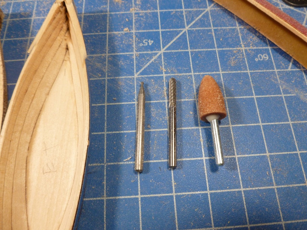
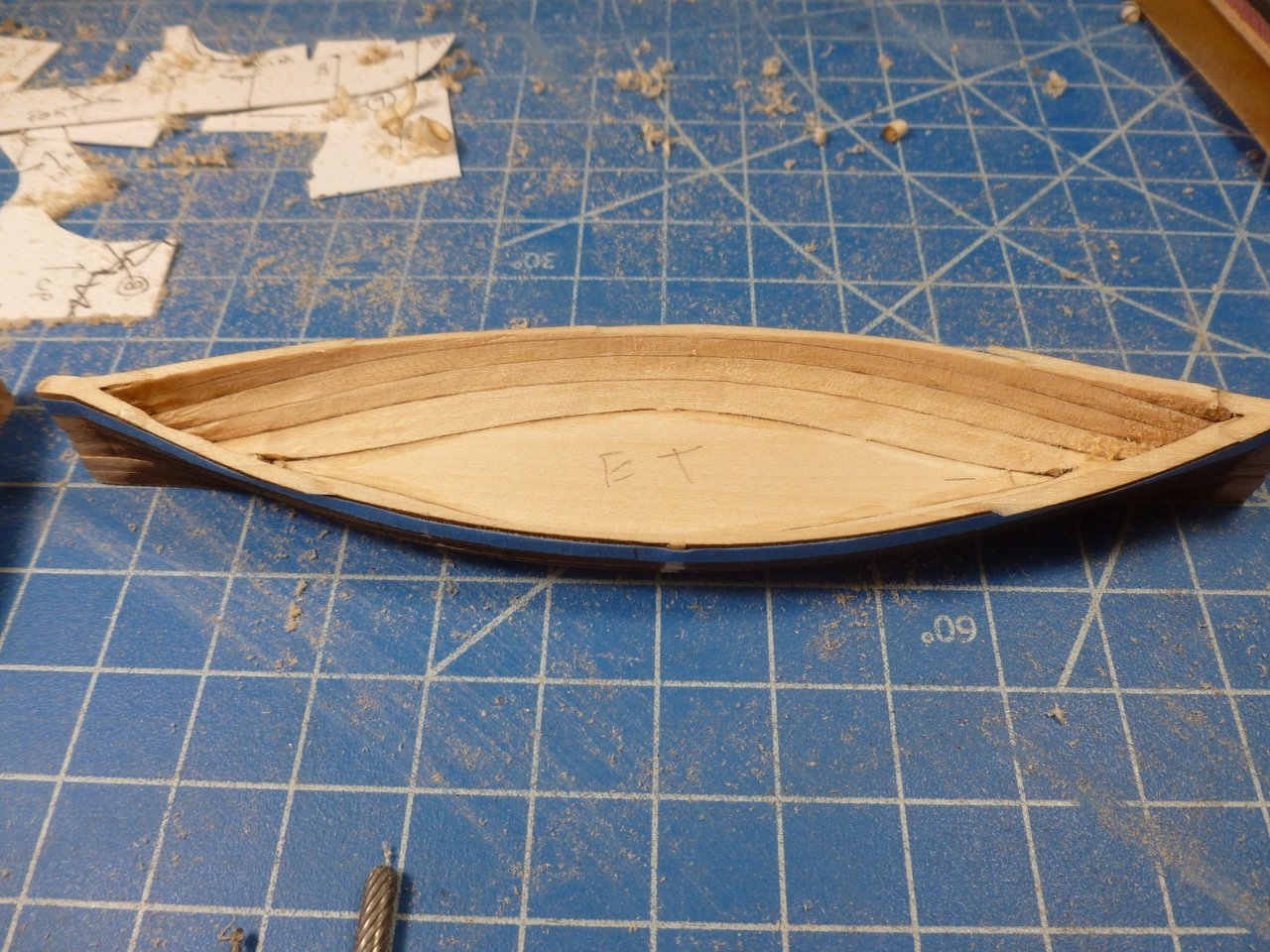
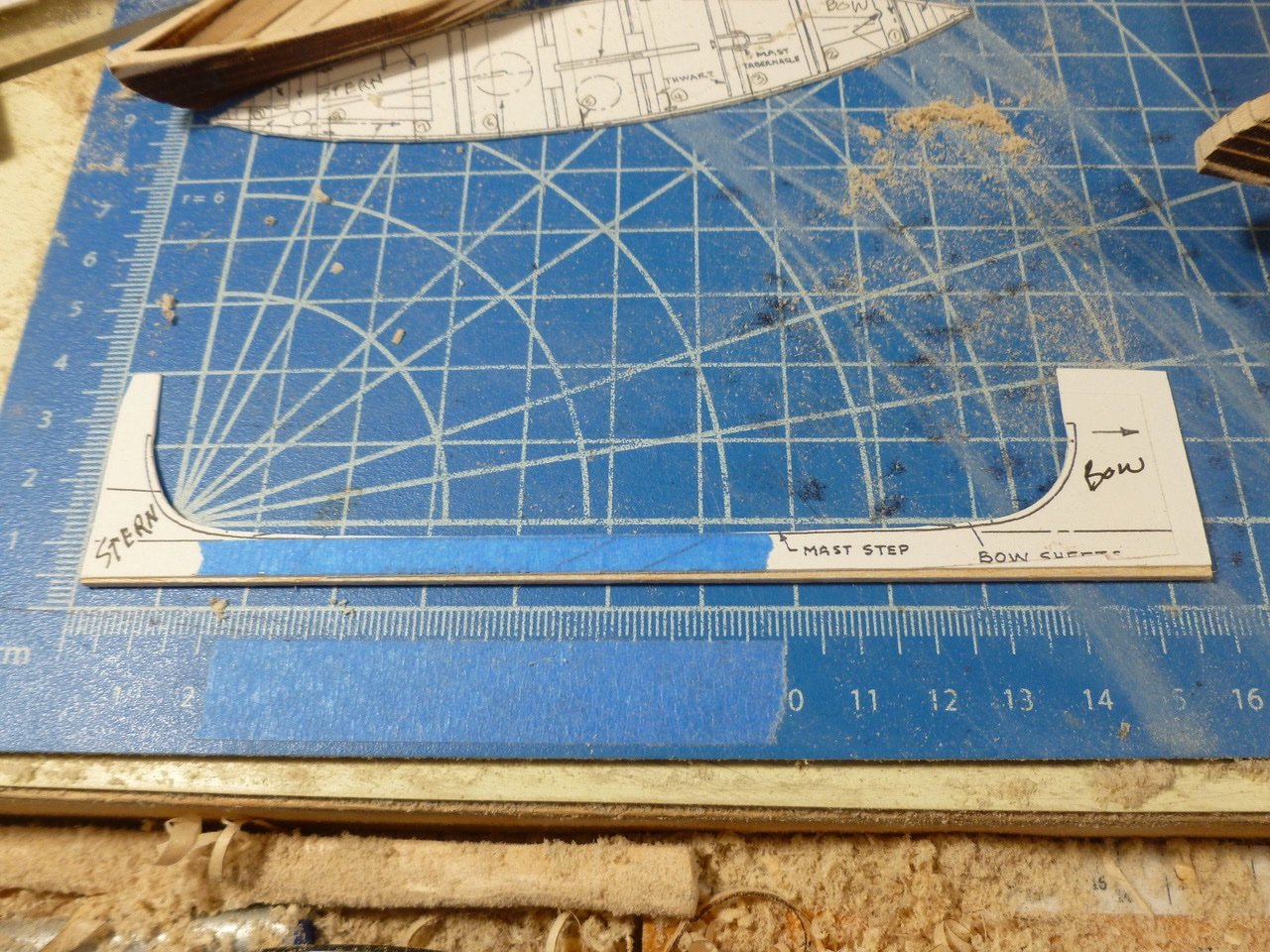
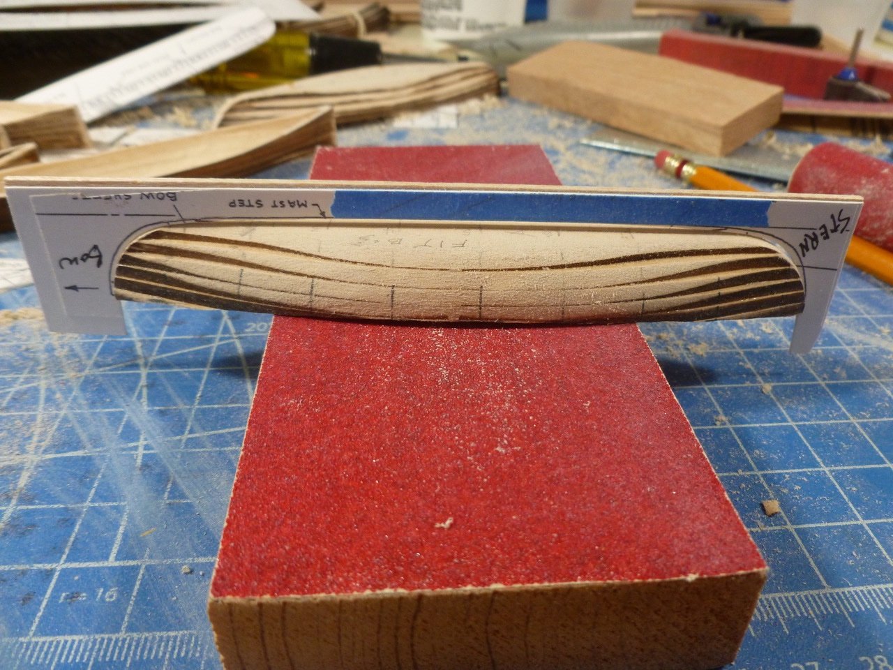
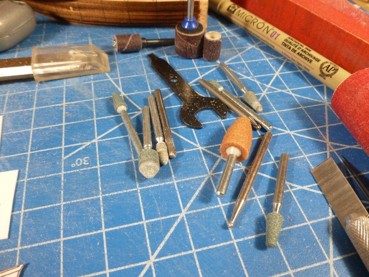
To those who stopped by or gave likes, thank you for your interest and enthusiasm. Whaaaaale Boaaaaat proggggggressss. It feels like I’m in slow motion working my way through carving and sanding the whale boat hulls, but considering ongoing family health issues, caregiving and the rather abrupt passing of a relative the carving process has been therapeutic. Three Dremel bits worked best, for me at least. The side cutter was good at knocking off edges and rough shaping; the orange cone blended and smoothed; and the tiny tip was helpful in the narrow spots at bow and stern. A sample shows reasonably good carving for the interior (I think). More work needed at bow and stern although some of it will be covered (I hope). Once I had the technique the remaining interiors went fairly quickly, maybe an hour or two each. The over-width bits of sheer line at bow and stern should disappear when I do the exterior sides. To keep the overall length of whale boats consistent I made another template to place along the keel line, taking care to cut the template on the hull line so I will have space to add the keel, which I expect will be a strip of styrene. I started the template with a copy of the profile, spray adhesived to Bristol board, but I didn’t leave enough meat along the bottom so I added a wood strip for stiffness. After sawing off the tabs at each end I sanded the curves with the Dremel drum sander, followed by sanding blocks. Once the boats are all the same length I’ll attack the exterior sides and bottom. The exterior sanding in the photo above is part of a test. Thanks for viewing. Steve
-
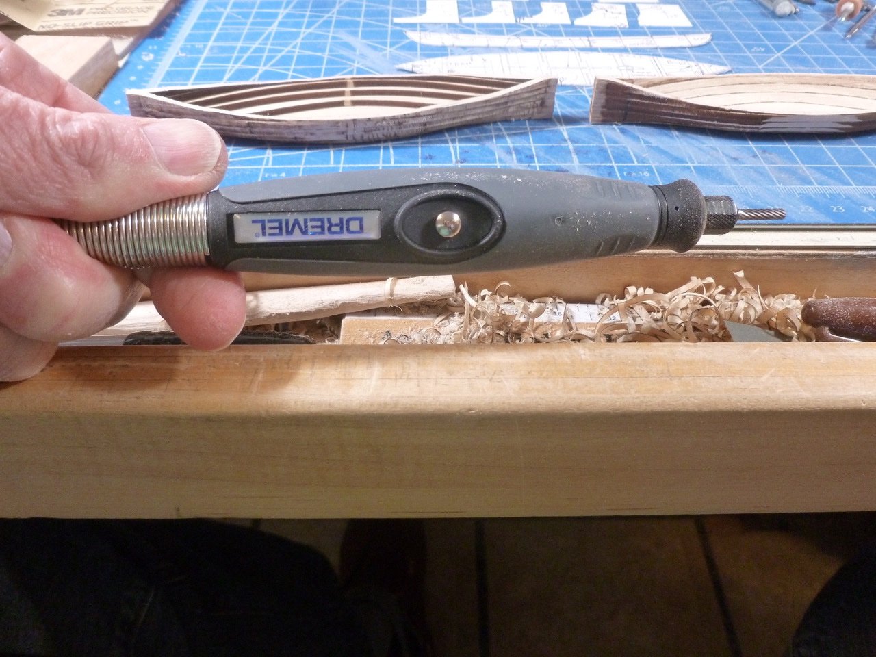
To those who stopped by or gave likes, thank you for your interest and enthusiasm. David, I did see your log comment about cutting the boats, but I was afraid I’d make a mess of the saw cut over the length of the boat, or end up making the halves less than symmetrical. Rookie, I used the side elevation template to draw a sheer guideline. There is a lot of material to be removed so I am using a full size chisel for the bulk of it, and the Dremel to get close to the line. Turning boats to dust. It’s amazing how much stuff I need to carve, gouge, plane and sand all the whaleboats. But I’m creeping ahead. Dremel bits have all been given an opportunity to shine. I copied details from the drawings and spray adhesived them to Bristol board. Station numbers are proving helpful but the ones I put on the outside bottom hull centerline have been most useful since they will be the last ones to sand off. I’m not sure what the endgame needs be at bow and stern but this is where I’m at on the first boat. The new Dremel detail tool was sitting on the shelf until my hand and wrist got tired trying to hold the main tool steady. The detailer is so much lighter it may make sanding almost fun. Thanks for viewing. Steve
-
JJ, It sure is a great learning opportunity! The jig should still work without the bottom slice. I’m experimenting with ways to carve or sand or Dremel the interior. You’re right, it’s a bit of a pig to get to all the corners and edges.
-
Steve, Very handsome indeed. Thanks for sharing and for your tips. Steve
-
Thanks Rookie. I appreciate your feedback. A Duh moment: While prowling around the shipyard this morning I found a wealth of whale boat detail on sheet 4, including a tiny lines drawing showing the station cross section profiles. The details also show just how thin the skin is intended to be. Frightening to say the least. Off to the copier to make some templates. Thanks for viewing. Steve
-
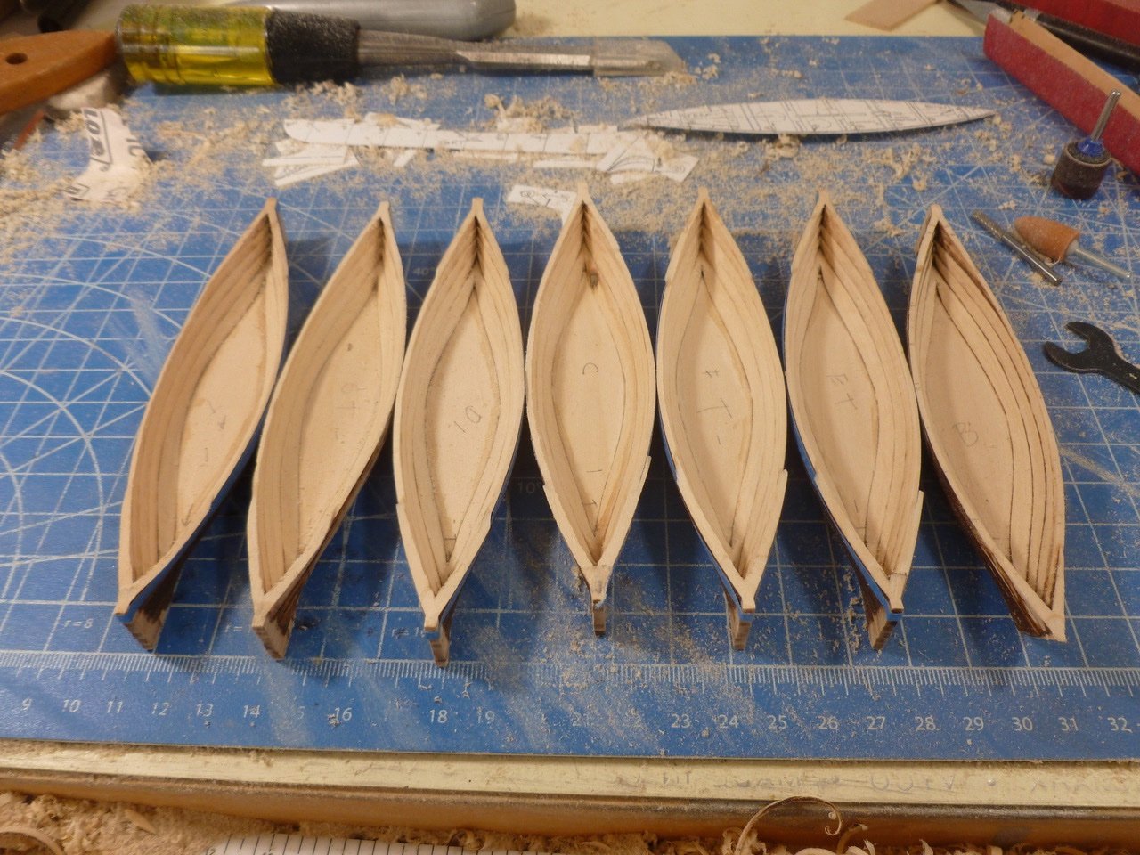
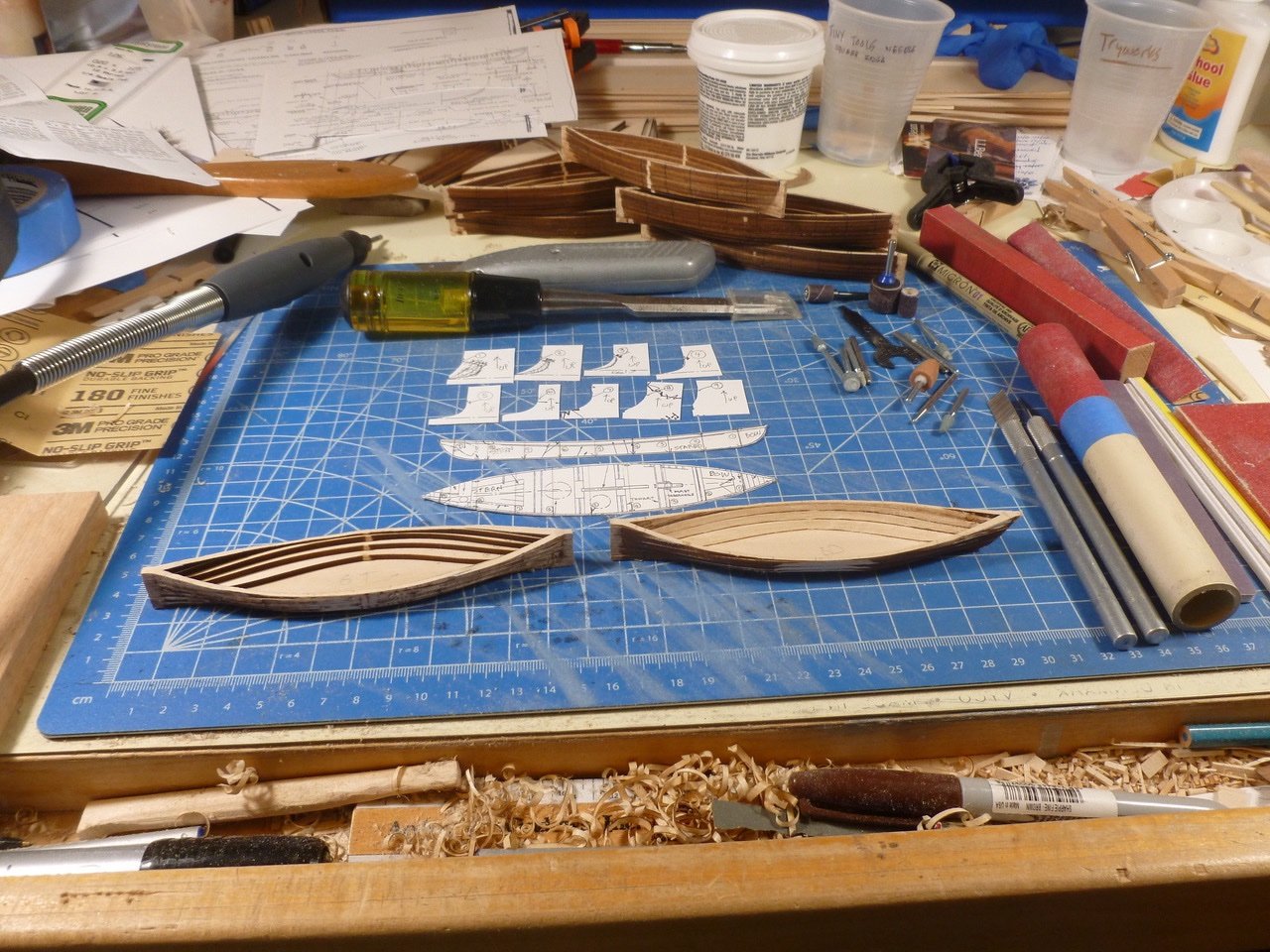
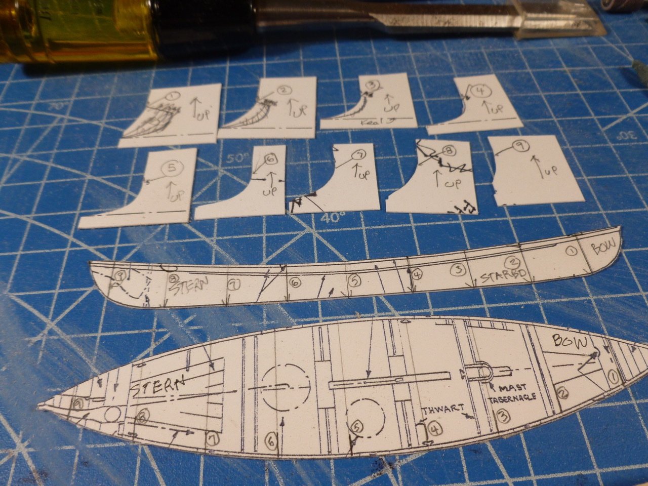
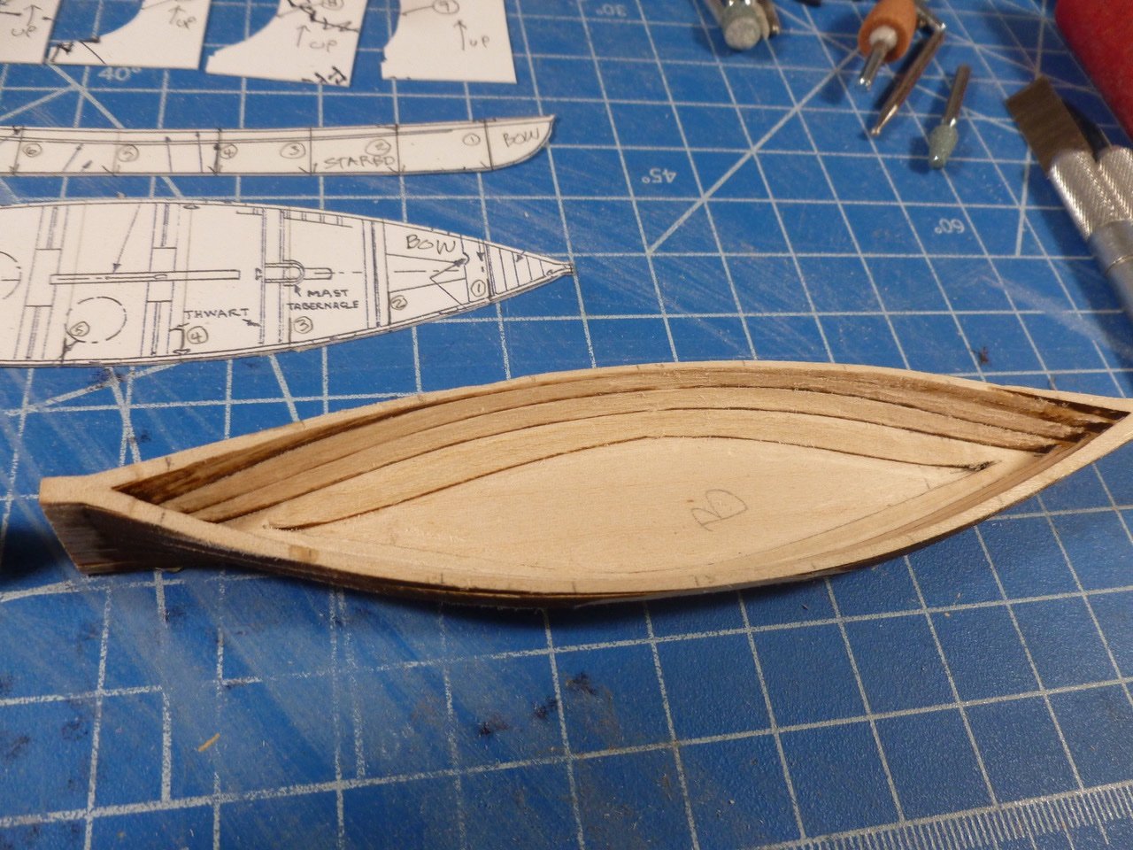
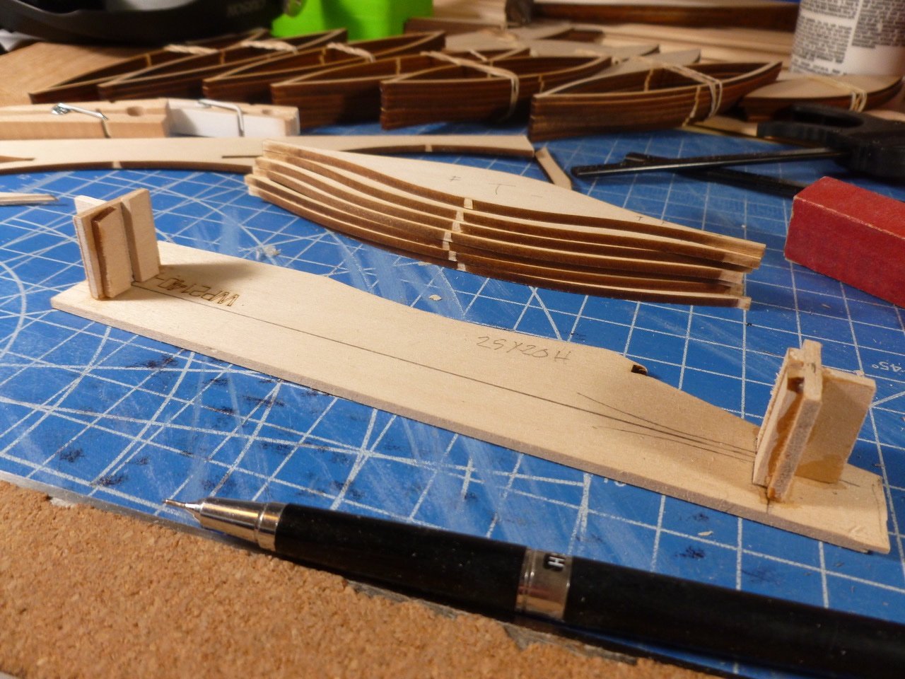
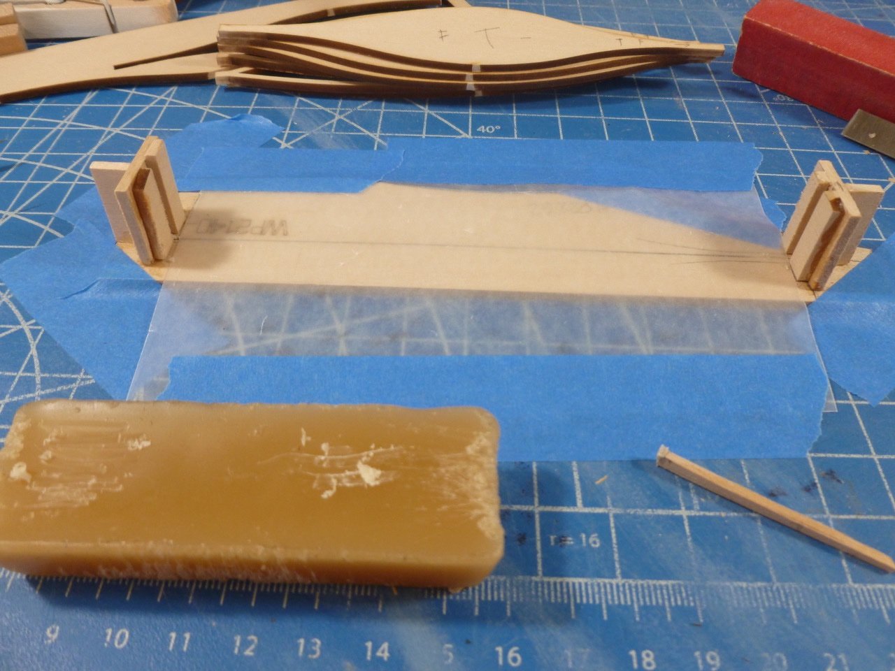
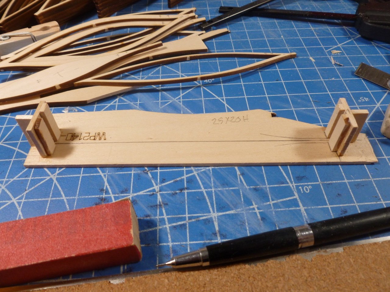
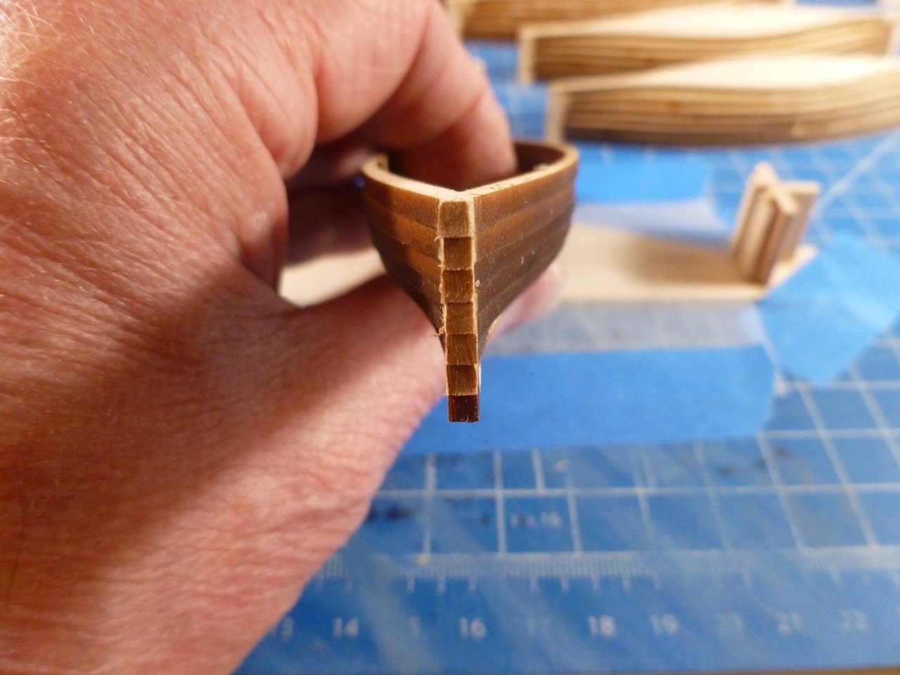
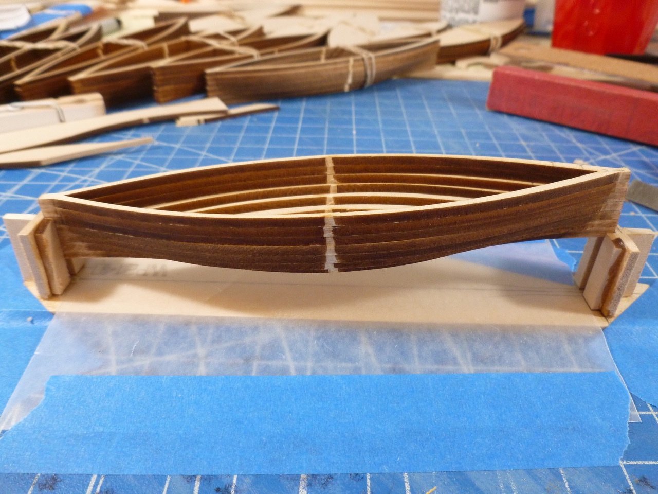
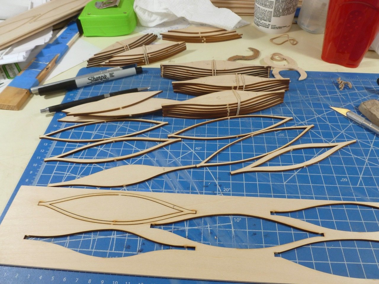
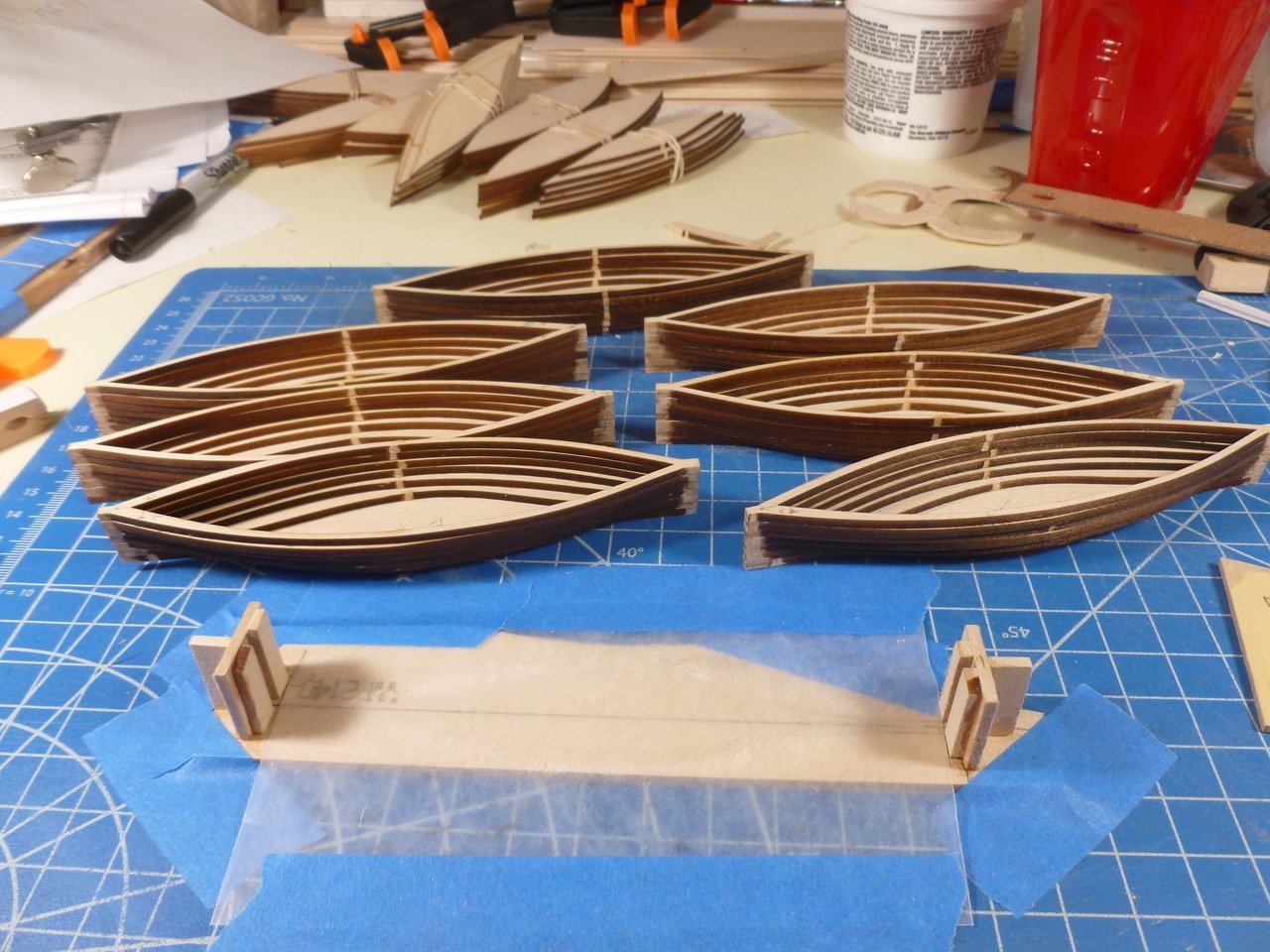
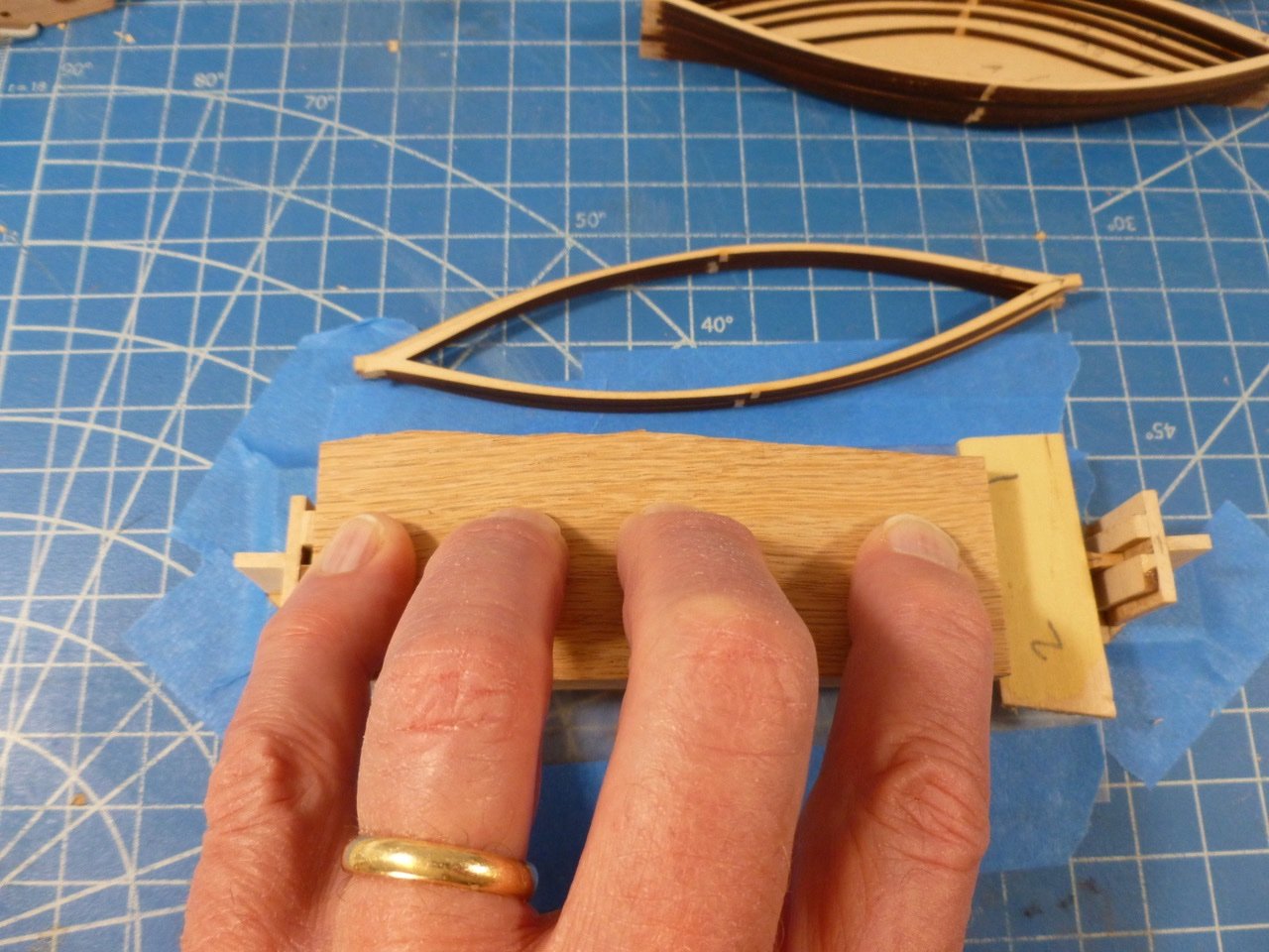
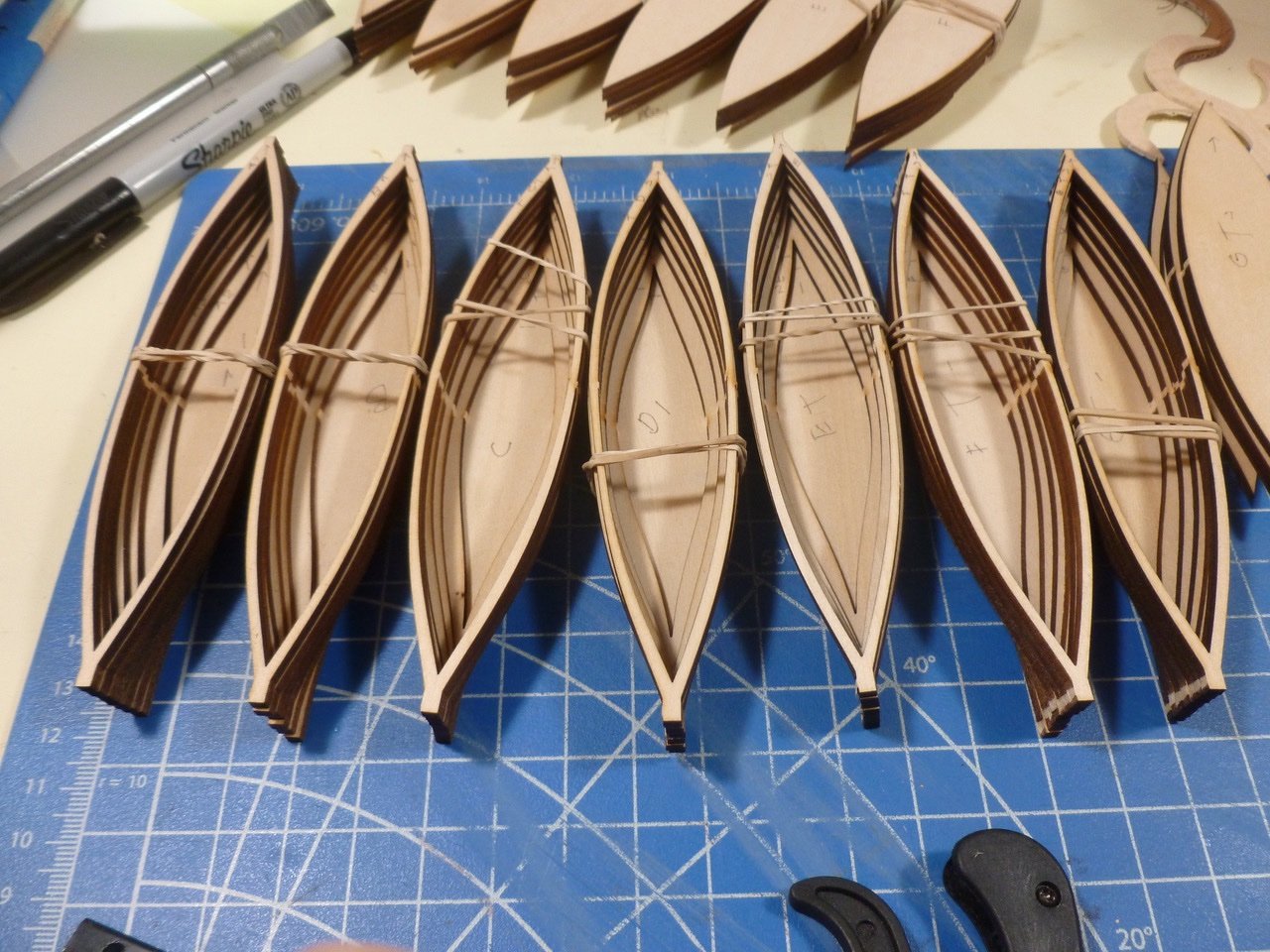
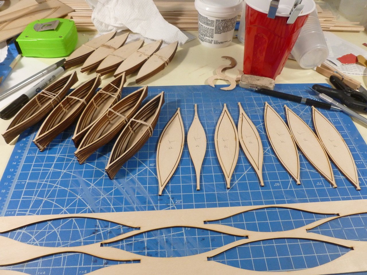
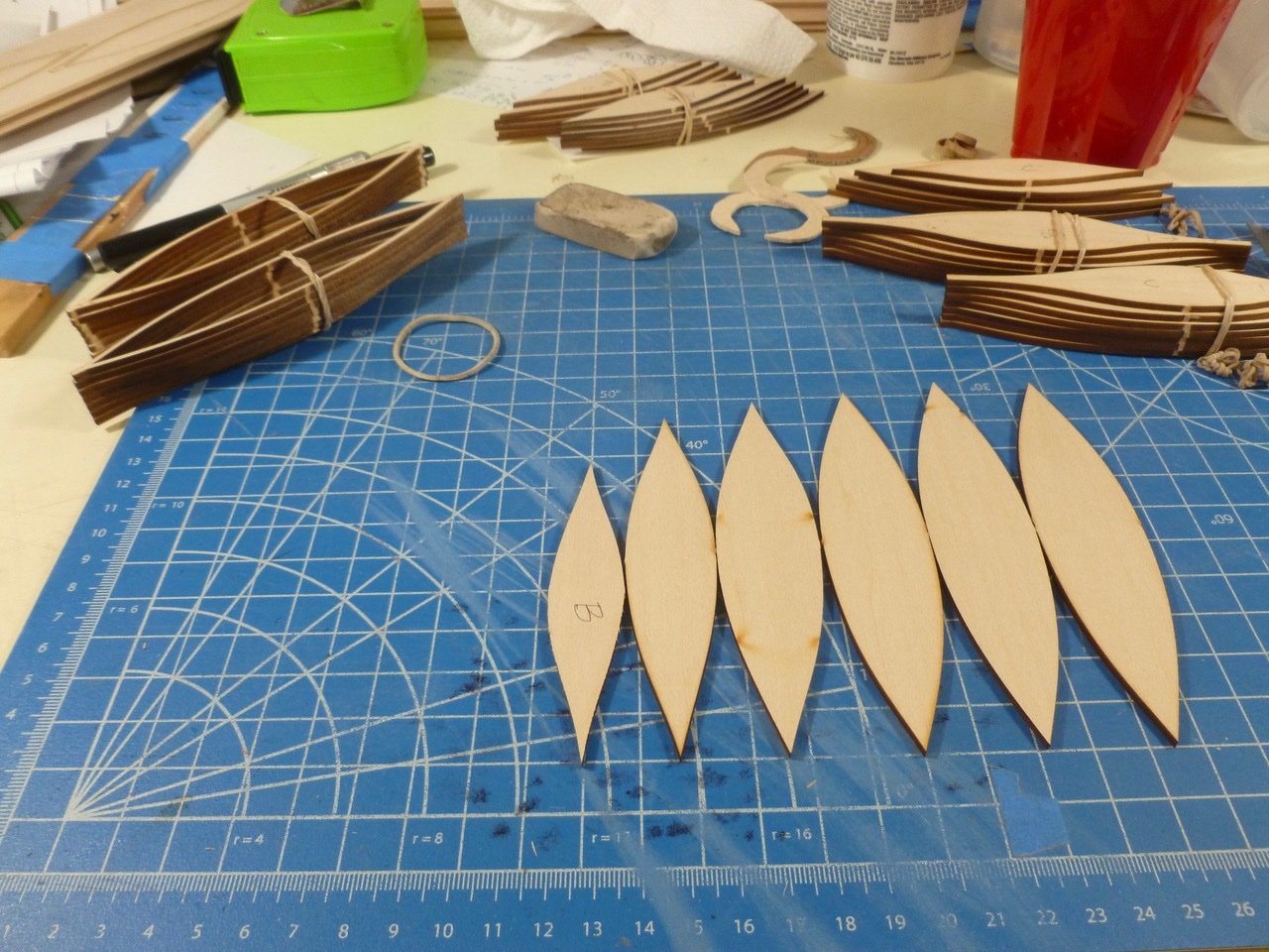
To those who stopped by or gave likes, thank you for your interest and enthusiasm. David, I'm glad I could brighten your day. Your CWM brightens mine every time I check the photos to see what's possible to achieve. Boats, boats, boats. Since I’m in the mode of building small bits and pieces I decided to tackle the whale boats. Seven laser cut pieces, with one boat per piece and seven “slices of bread” per boat make lots of opportunities to mess up. The first question was what order the slices should be in. Before I started cutting I labeled each boat slice with a letter to designate the boat, a T for “top” and an arrow pointing toward one end. One end is slightly wider than the other which helped the orientation. As I separated the slices from the carrier sheets I thought the waste pieces in the center of each slice might come in handy so I labeled each group of waste (A, B, C, etc) to match the corresponding sets of slices. Then I realized that the boat interior gradually gets bigger from bottom to top. I arranged the center waste pieces going from smallest to largest and matched them up to the slices. After that I added a number to each slice, again going from bottom to top. After loose fitting and rubber banding the slices the next questions were how to align them when gluing and how to clamp the thin edges so they wouldn’t slide out of position. I tried mini-bar clamps, with and without clothes pins but this looked awkward and would need to be assembled and disassembled for each slice. I settled on using a jig. At each end there were two vertical strips set to the width of the slice tabs, mounted on a backing piece and supported with a little strong-back. To help ensure I could remove a completed boat from the jig I rubbed a bit of beeswax in the end grooves and covered the base plate with wax paper. The jig turned out pretty tight fitting so I sanded the laser char from each tab end, then stacked the slices in reverse order starting with the bottom slice at the top. This way I could take a slice from the top, add glue (I used CA) to the underside (except at the bottom slice) and place it in the jig. I used a scrap piece of oak and finger pressure to clamp each layer for about 30 seconds. The other piece of scrap clamping wood is there only because the oak wasn’t long enough. And that piece has no finger because it is on the shutter release. And the first boat actually lifted out with very little encouragement. A bow view shows the layers were reasonably well aligned. In fairly short order all boats were glued up and ready for sanding. Now I have to figure out how to get them to all look the same. I have a book on order, The Whaleboat: A Study of Design Construction and Use from 1864 to 2014 by Willits Ansel, which I hope will give guidance on details. Thanks for viewing. Steve
-
Chris, I am humbled by your kind feedback and support. Thank you. David, your blog is my instruction manual. I have started on whale boats and have your pics in my reference folder; you’ve set a very high bar indeed. Thank you Rookie, thanks for your ongoing support. The rope eyes are just thin slices of half round. To all who stopped by or gave likes, thank you for your interest. Work is going slow but I’ll have a whale boat update soon. Thank you again. Steve
-
JJ, Looking good! You’re way ahead of me on the hull. Since I’m in a tiny parts mode I’m working on whale boats. Thanks for sharing. Steve
-
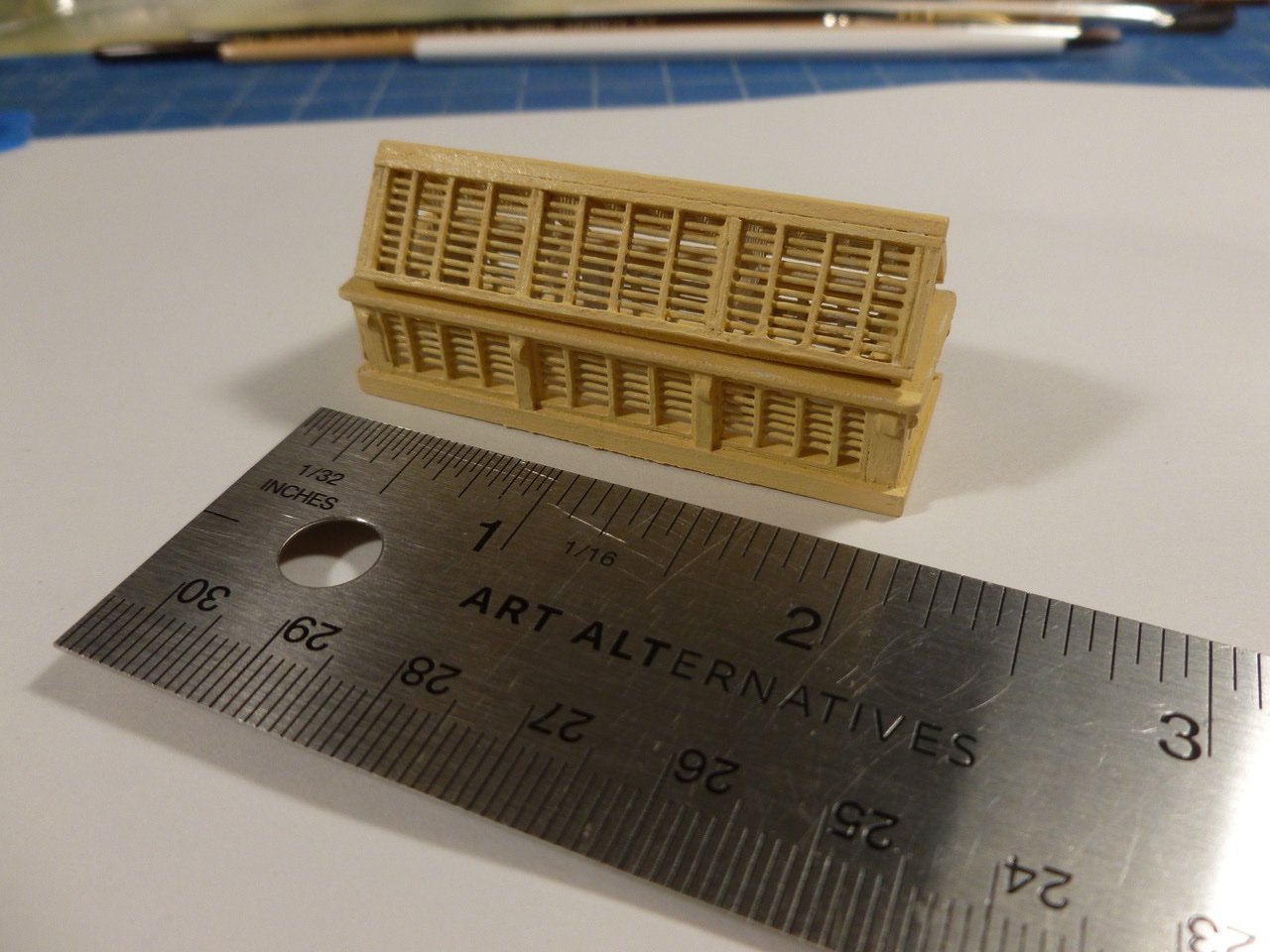
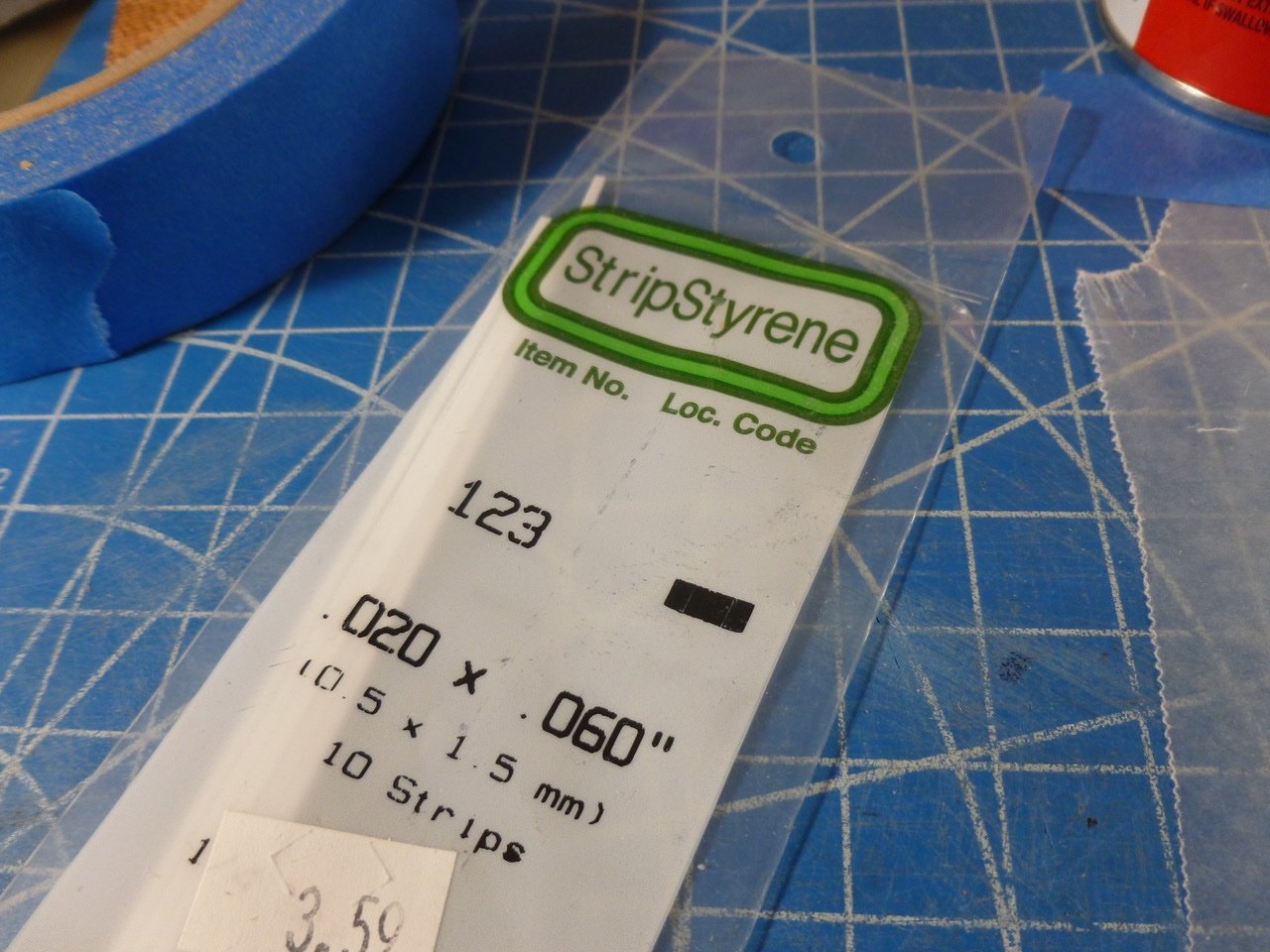
To those who stopped by or gave likes, thank you for your interest and enthusiasm. Rookie and JJ, thank you for hanging in there and for your kind remarks. After sanding, vacuuming and a swipe with the tack cloth I applied a primer coat of B-I-N to the skylight. This is very fast drying so I slowed it down a bit with a few drops of ammonia mixed 1:1 with water. Even then I had to rinse the tiny brush repeatedly with the same mix to keep it from clogging since the work was so slow, about three hours. I also primed the inside, mainly on the styrene bits since I understand they don’t like light. I applied a coat of acrylic house paint, which is also fast drying and a bit thick so I slowed it down with a few drops of retarder. It helped keep the paint from skinning over in the plastic palette cup and also helped the flowability. The retarder is Floetrol by Flood. The smallest available is a quart but at about $10 it was quite a bit cheaper than little craft size bottles of other stuff. I guess I'll be flowin' smoothly for life. The roof bars aligned well from one side to the other and with the side bars. I couldn’t resist throwing in another scale picture. The bump outs (poor terminology I know) on the side were cut from 0.020 half round styrene, which is out of scale but adds some interest. Now all I need is a ship deck. Thanks for viewing. Steve
-
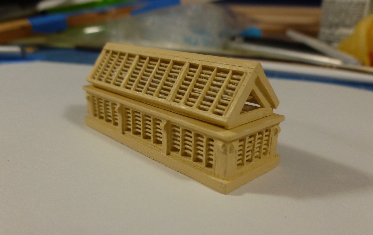
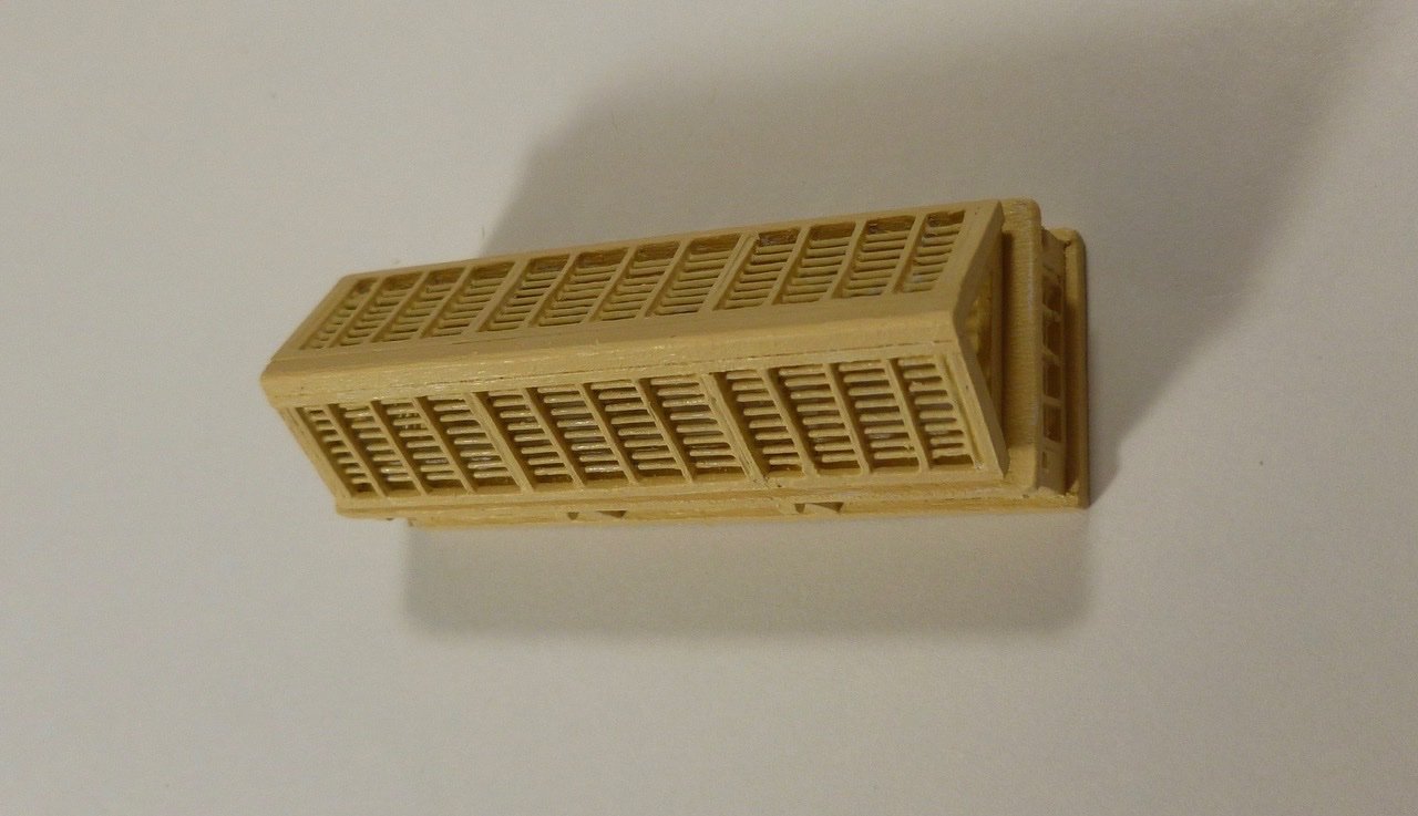
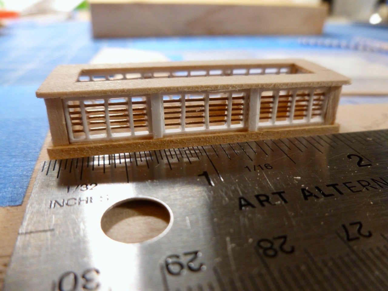
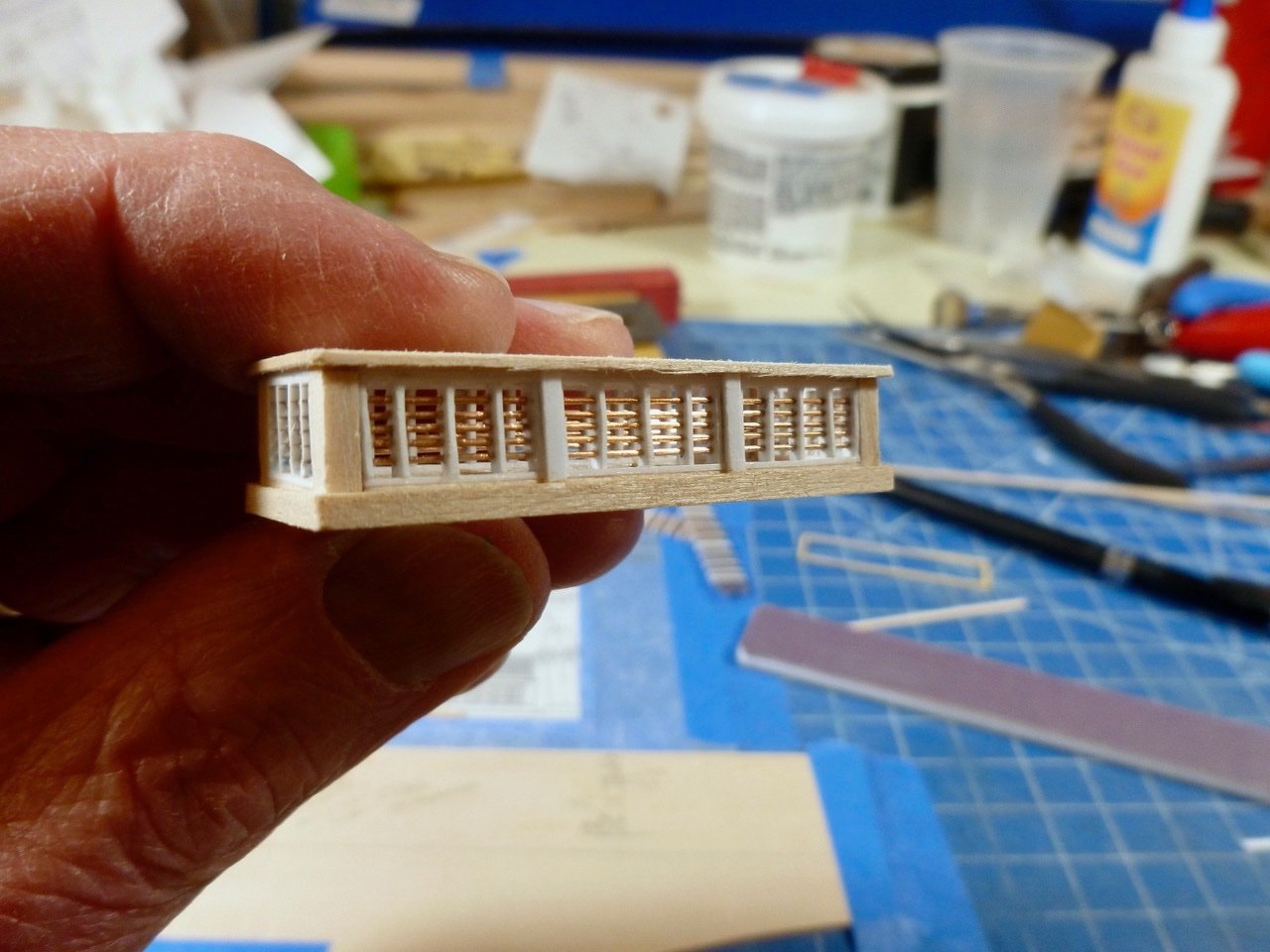
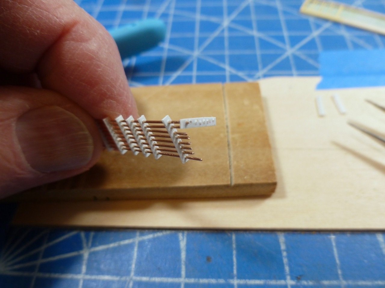
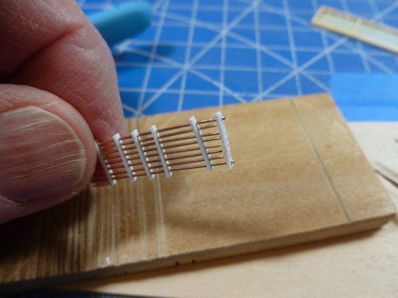
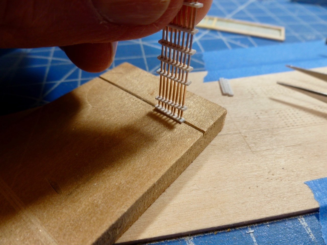
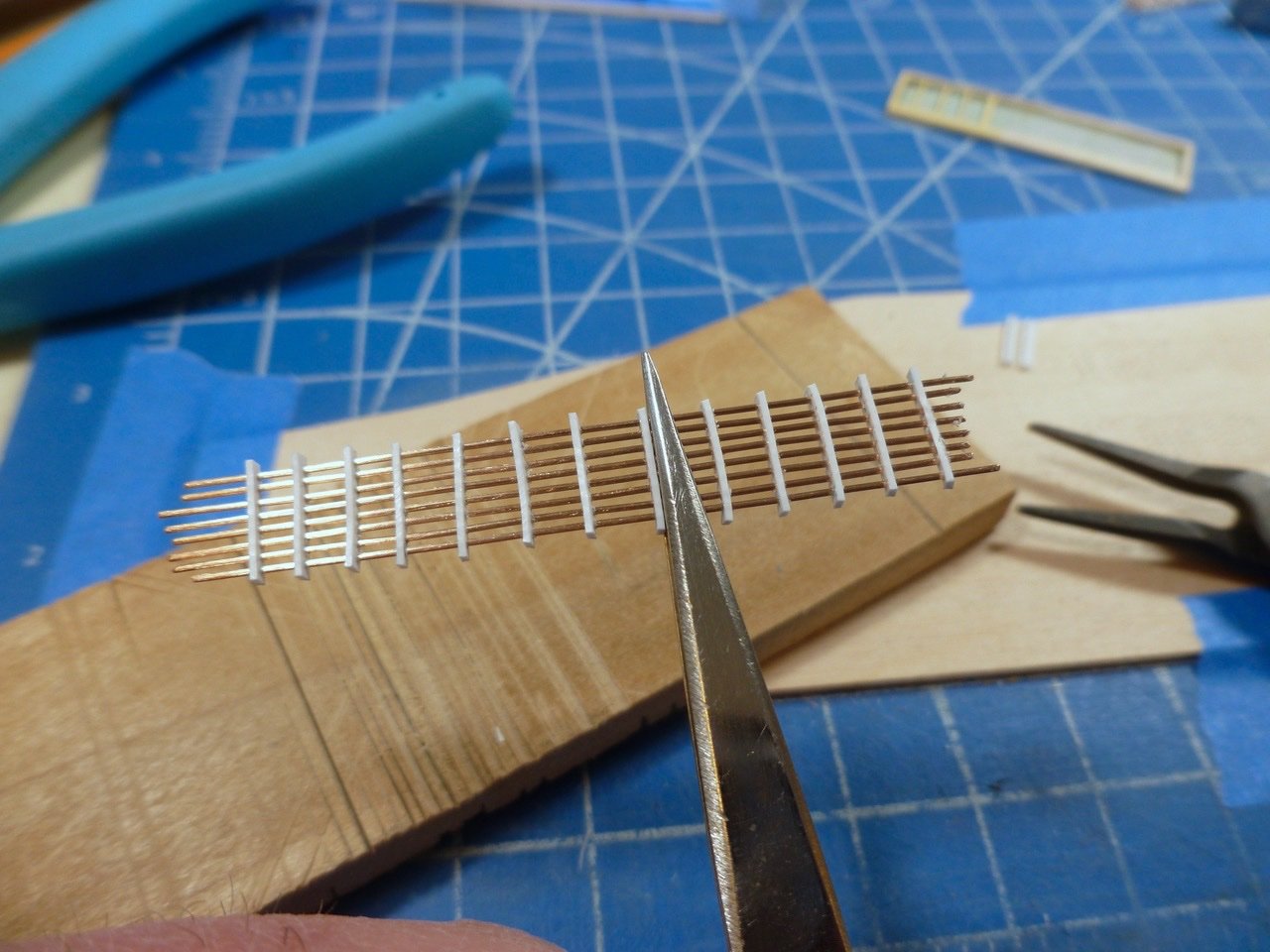
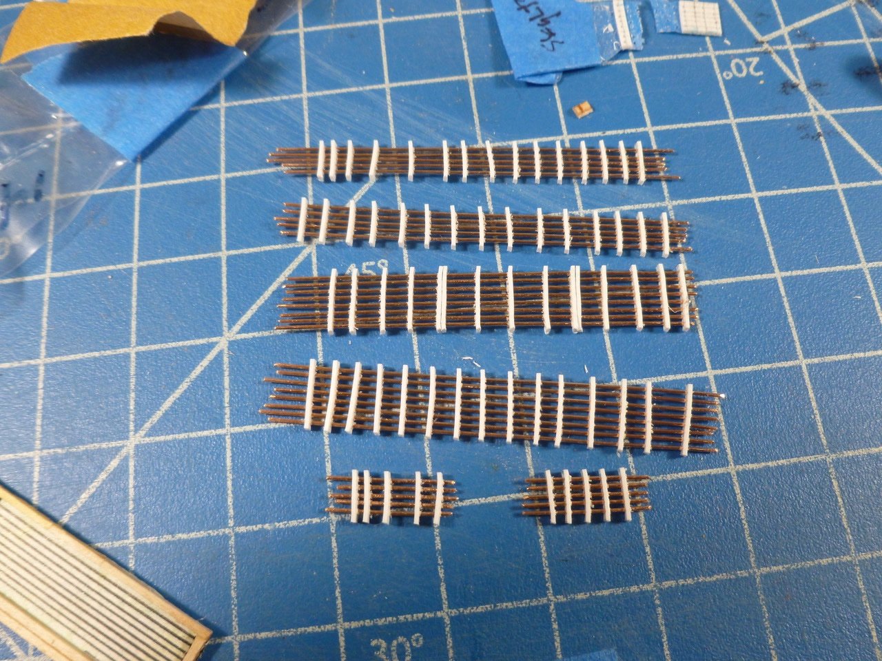
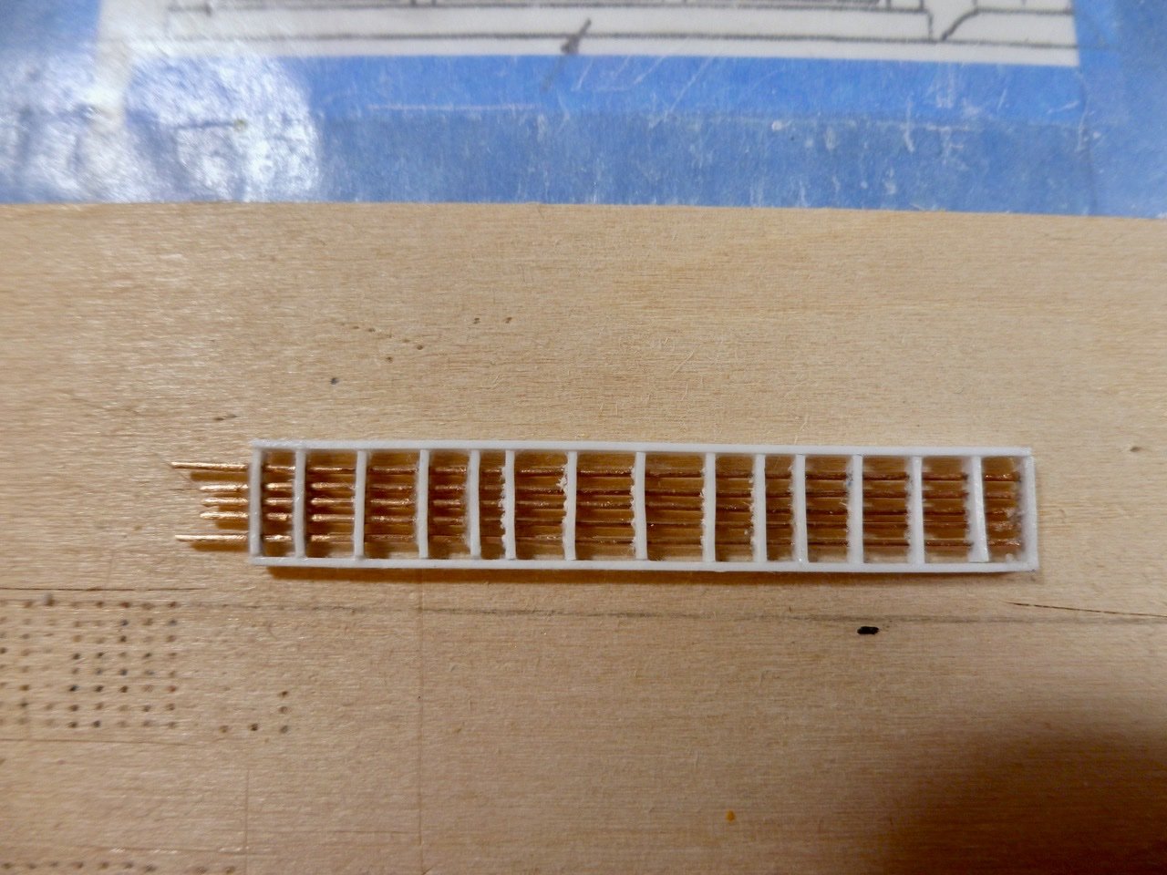
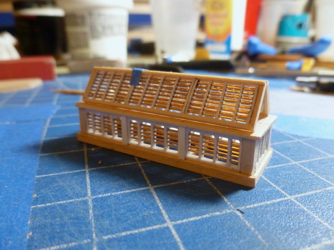
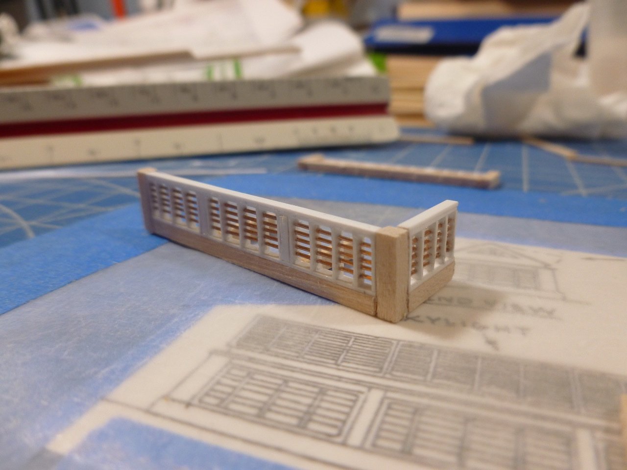
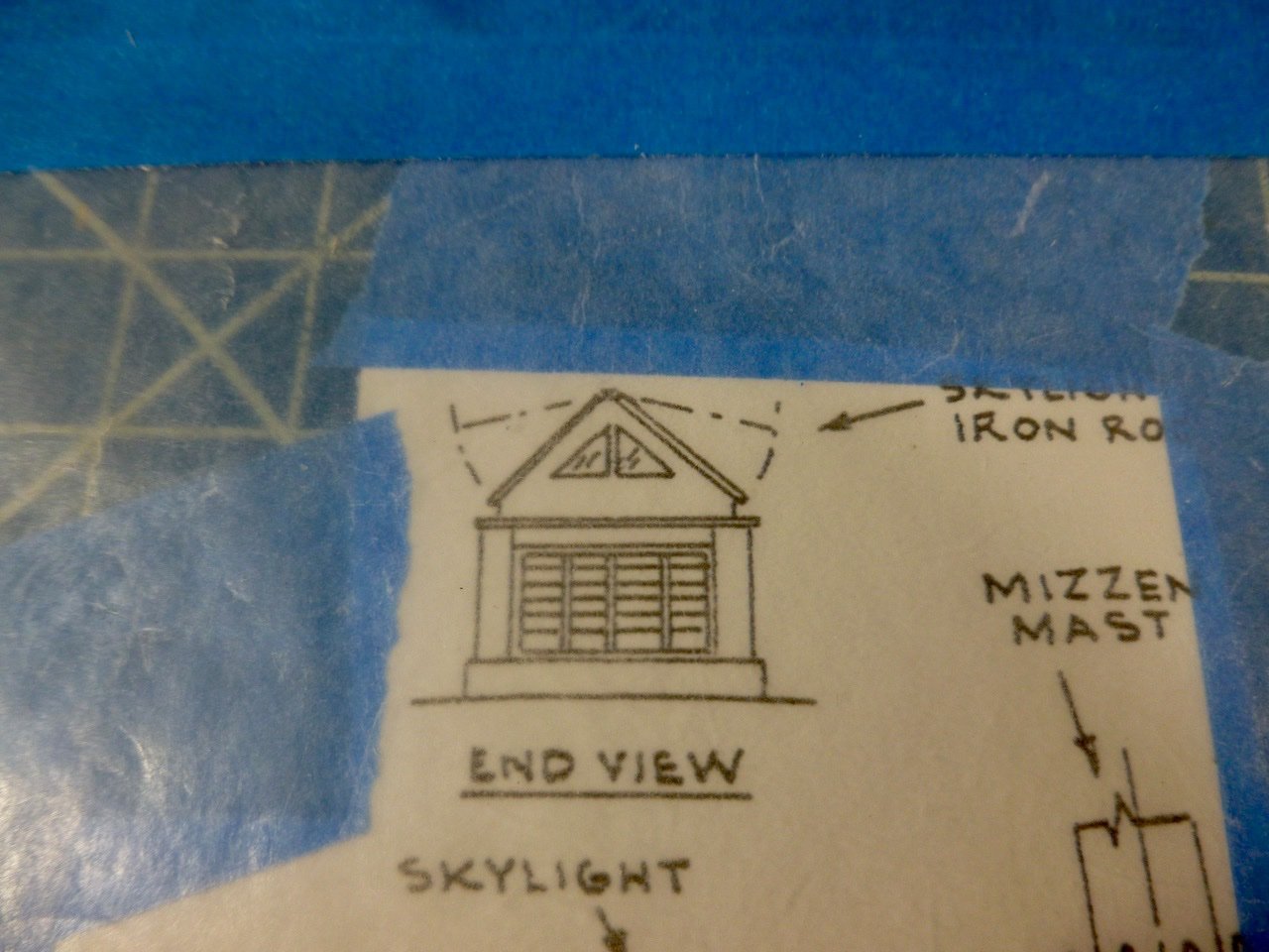
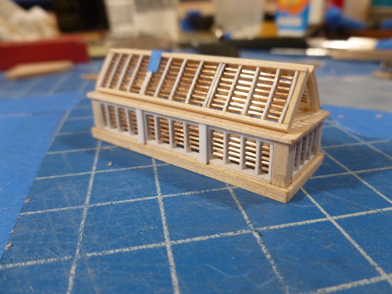
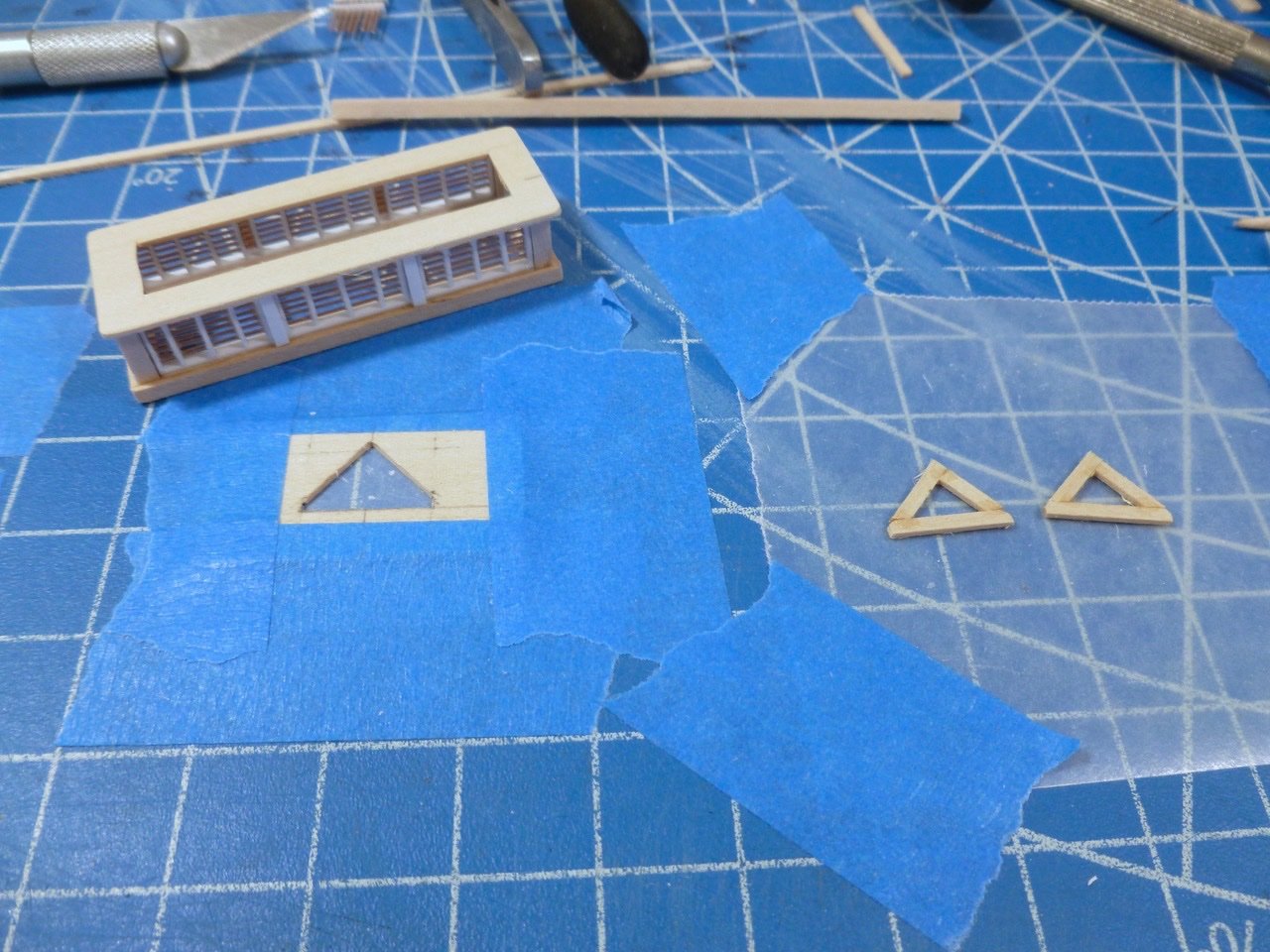
To those who stopped by or gave likes, thank you for your interest and enthusiasm. Rookie, thank you for your kind comments. I’ve seen your work. You deserve to upgrade “rookie” to better reflect your skill. The skylight is chugging along at a pace that my old eyes can focus on it. Many bars, many muntins so how do they all come together? There may be better ways but this is how I threaded all the muntins onto the bars. A handy jig was a shallow and narrow slot in a piece of wood to support the muntin while the bar was inserted. Two closely spaced razor saw slots provided room for the bar. Once all the muntins for a section are lined up with tops and faces all pointing in the same direction I worked across the first muntin to insert the bars. After the first muntin I started with the first bar of the second muntin after pulling the bar through so it was slightly longer than the others. The slightly wavy line of holes in the bar above shows why it is important to keep adjacent muntins in order, with tops aligned and facing the same direction. Otherwise it's a much bigger challenge to thread the muntins onto the bars. I swung the muntin and inserted the last bar, which was also pulled through longer than the others. Once the last bar was in place, and assuming the muntins are in the same orientation as they were when drilled, the muntin can be leveraged and the remaining bars should align with the holes. I found that keeping the adjacent muntins fairly close to each other helped to keep the bars pointing in the right direction. Since the spacing did not allow for using tweezers between muntins I used a small screwdriver to encourage recalcitrant bars to get in their holes. Smooth tweezers were helpful in sliding the muntins along the bars. The styrene muntin material is relatively soft with all the holes in it, and required much fussiness to get the muntins sort of straight. After a fashion the bar units were ready. Adjusting the alignment was a never ending battle. Won some, lost some. I added caps to fully enclose the muntin bar units. Bar ends were snipped and sanded after CA was selectively added to a few muntins to keep them in place. I added a subbase under each wall unit and a second layer of capping on top to maintain the vertical dimension shown on the drawings. I split up the sections of bars as shown on the drawing with strips face-glued at the third points. After the walls were stood up I added the coaming base and more strips to build out the dividers between bar units. I cut a piece of 1/32 inch sheet to make a one piece base for the skylight roof assembly. The second photo above shows scale, which anyone with a passing interest in Morgan already knows but it is still cool. The skylight end view drawing shows the gable profile. I made a jig to match the profile but added a little to the peak height to accommodate the as-built dimension of the skylight roof panels. I made one for each end and one at each third point to help support the roof panels. After completing the roof panels I mocked up the full skylight, less the roof framing and gable ends. A backlit shot is below. Now the question is, what to do, if anything, about painting the inside of the skylight. I’m thinking it needs it but since most of the skylight will be tucked away and partially hidden…. Thanks for viewing. Steve
-
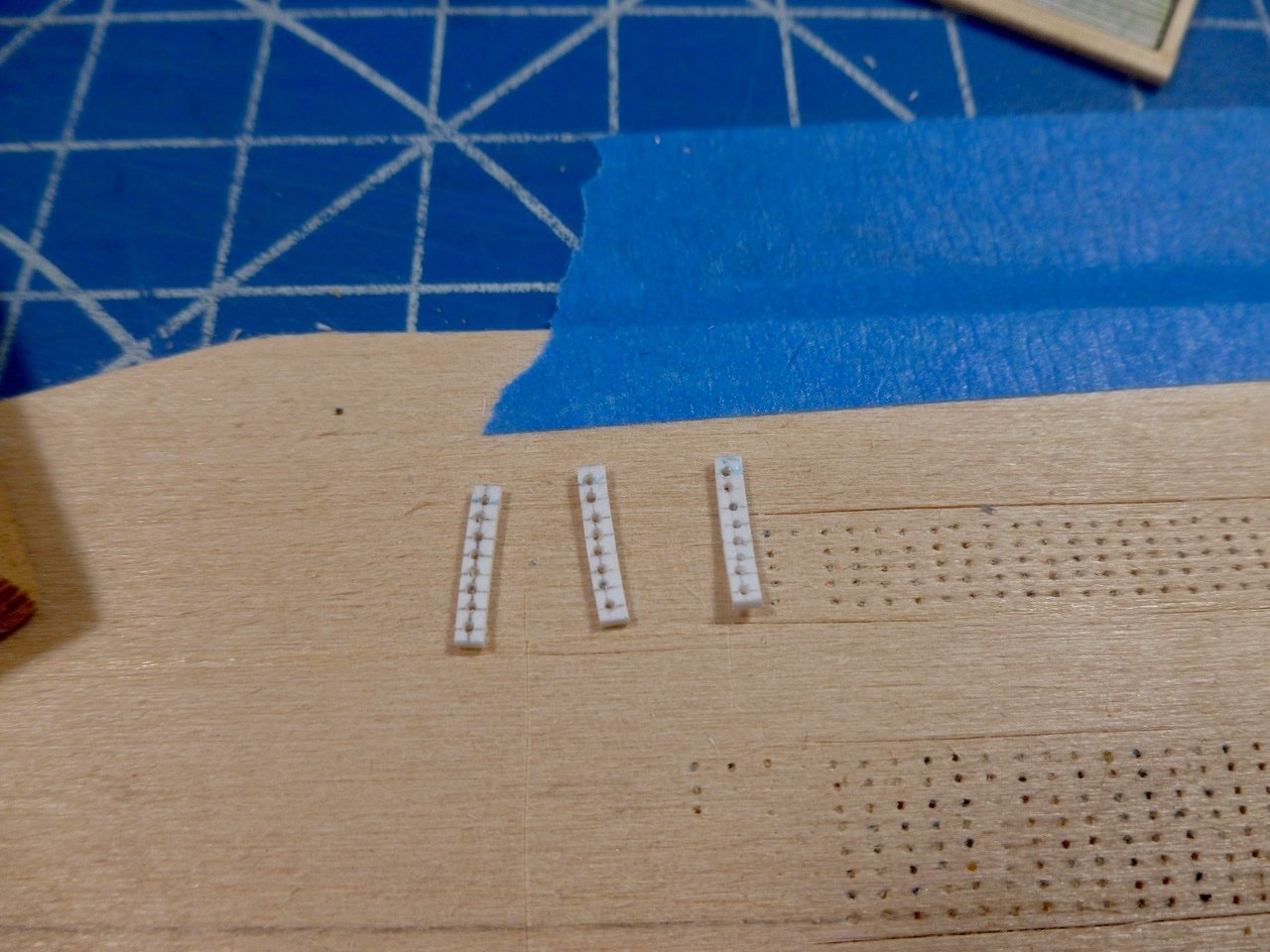
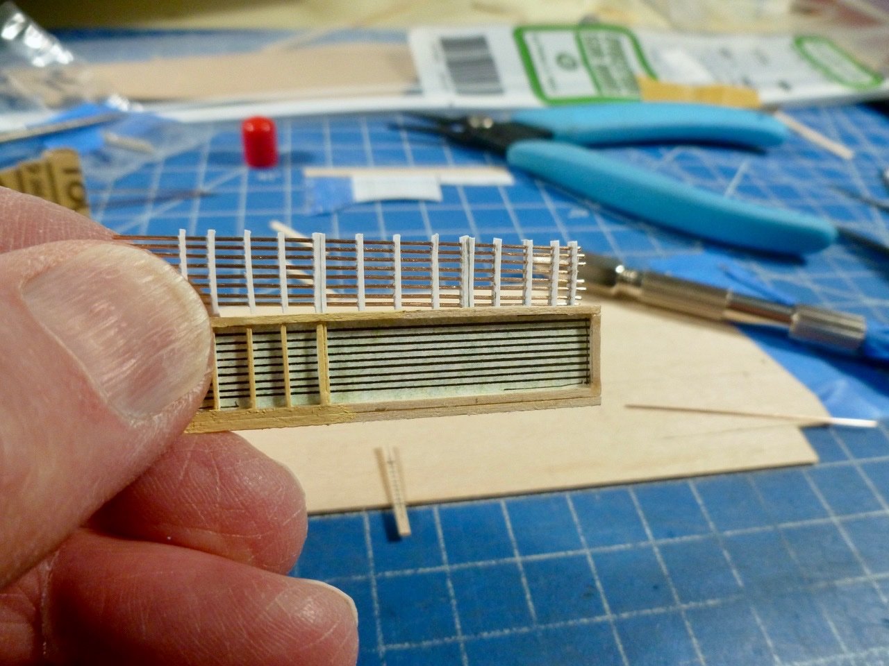
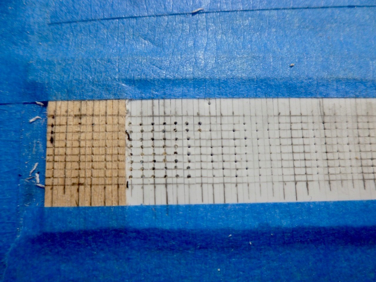
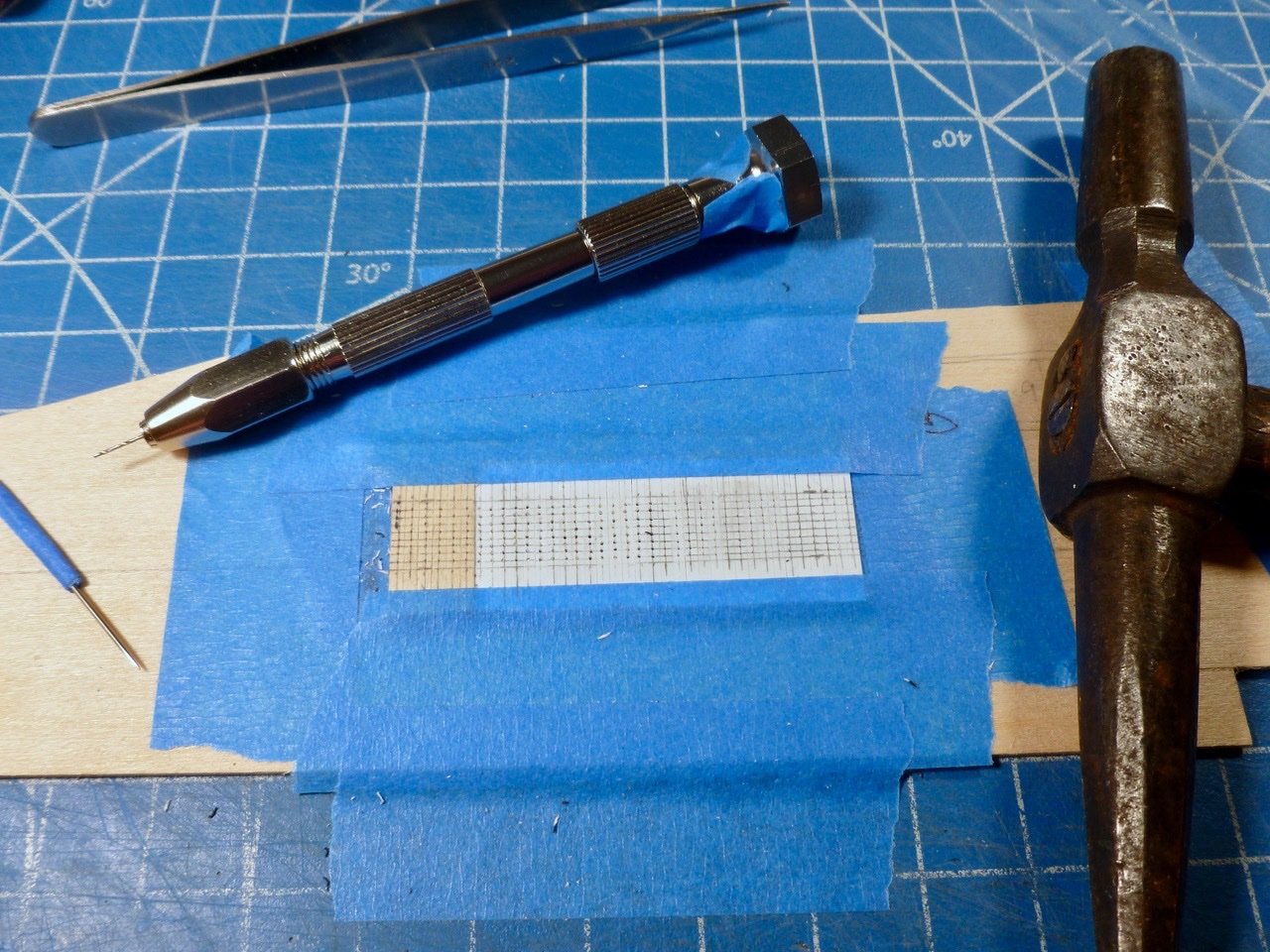
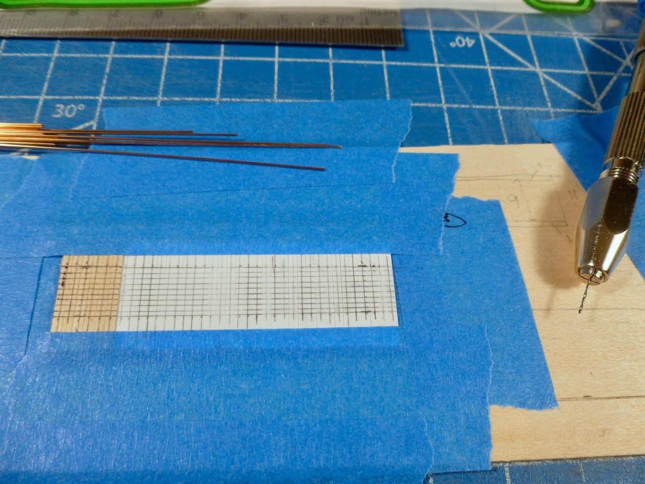
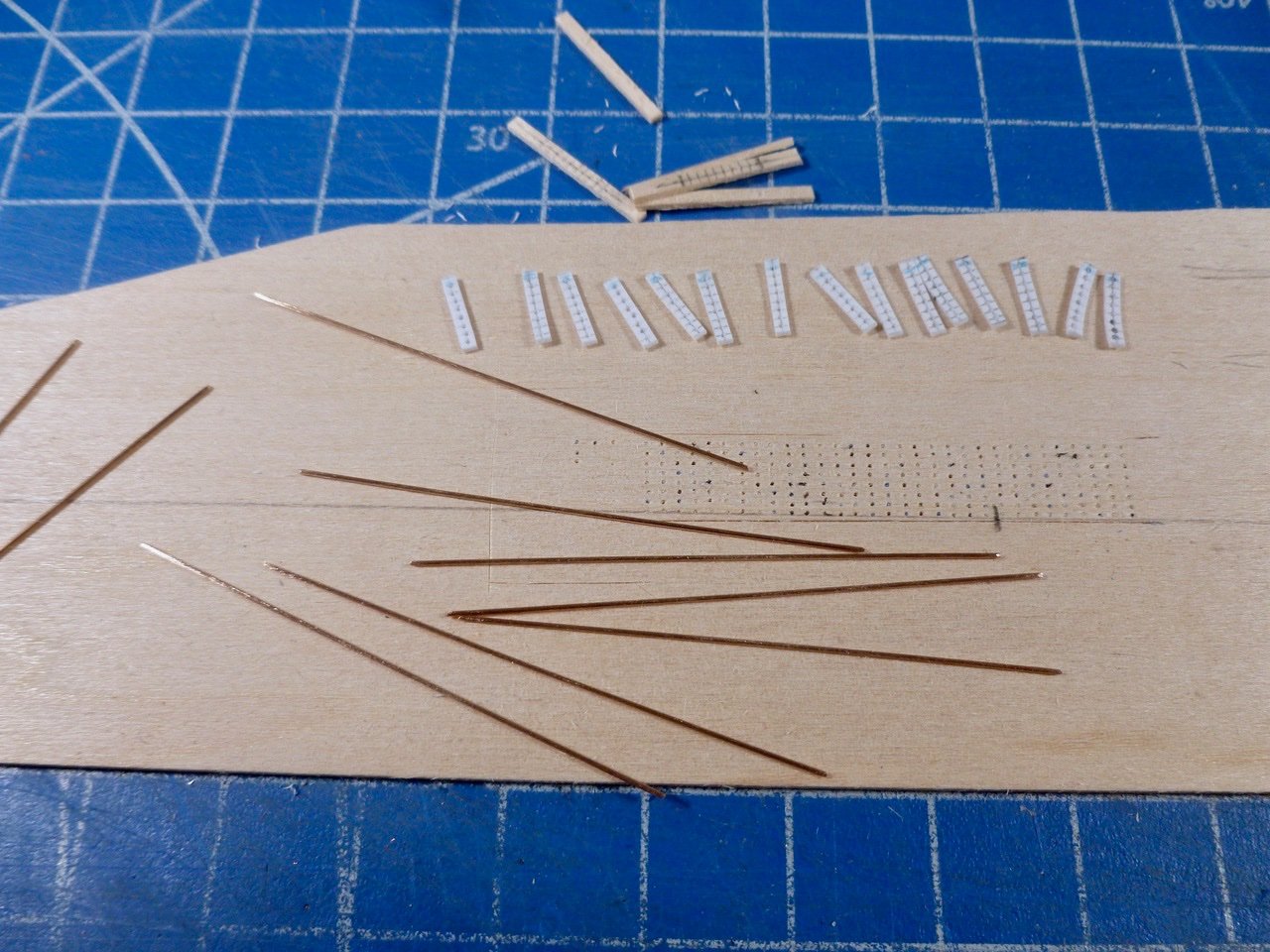
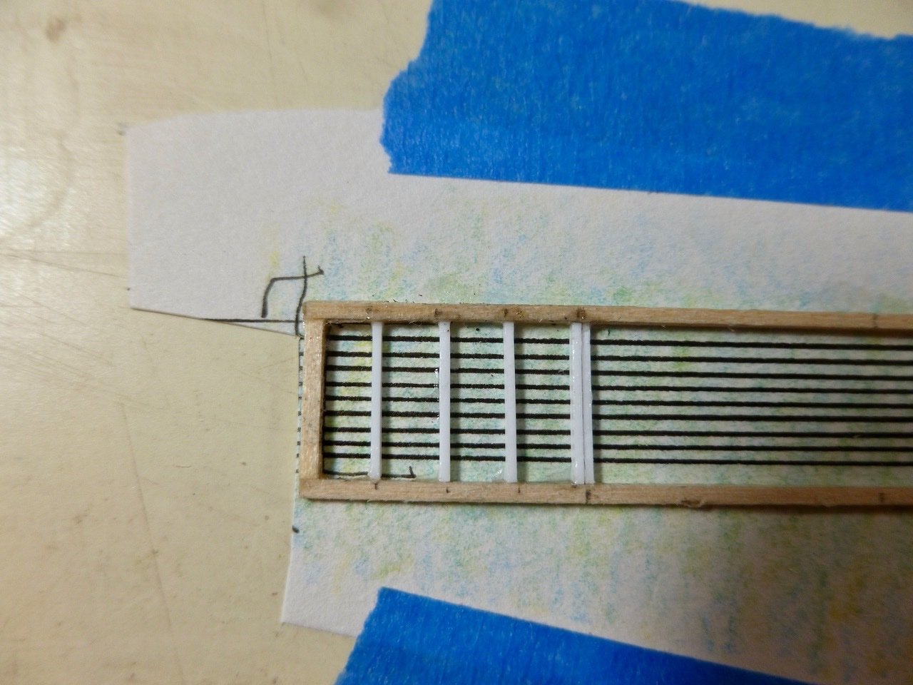
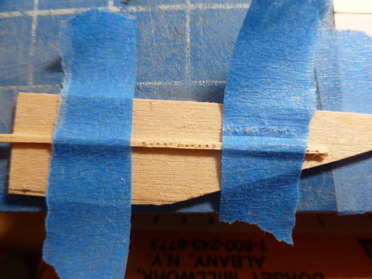
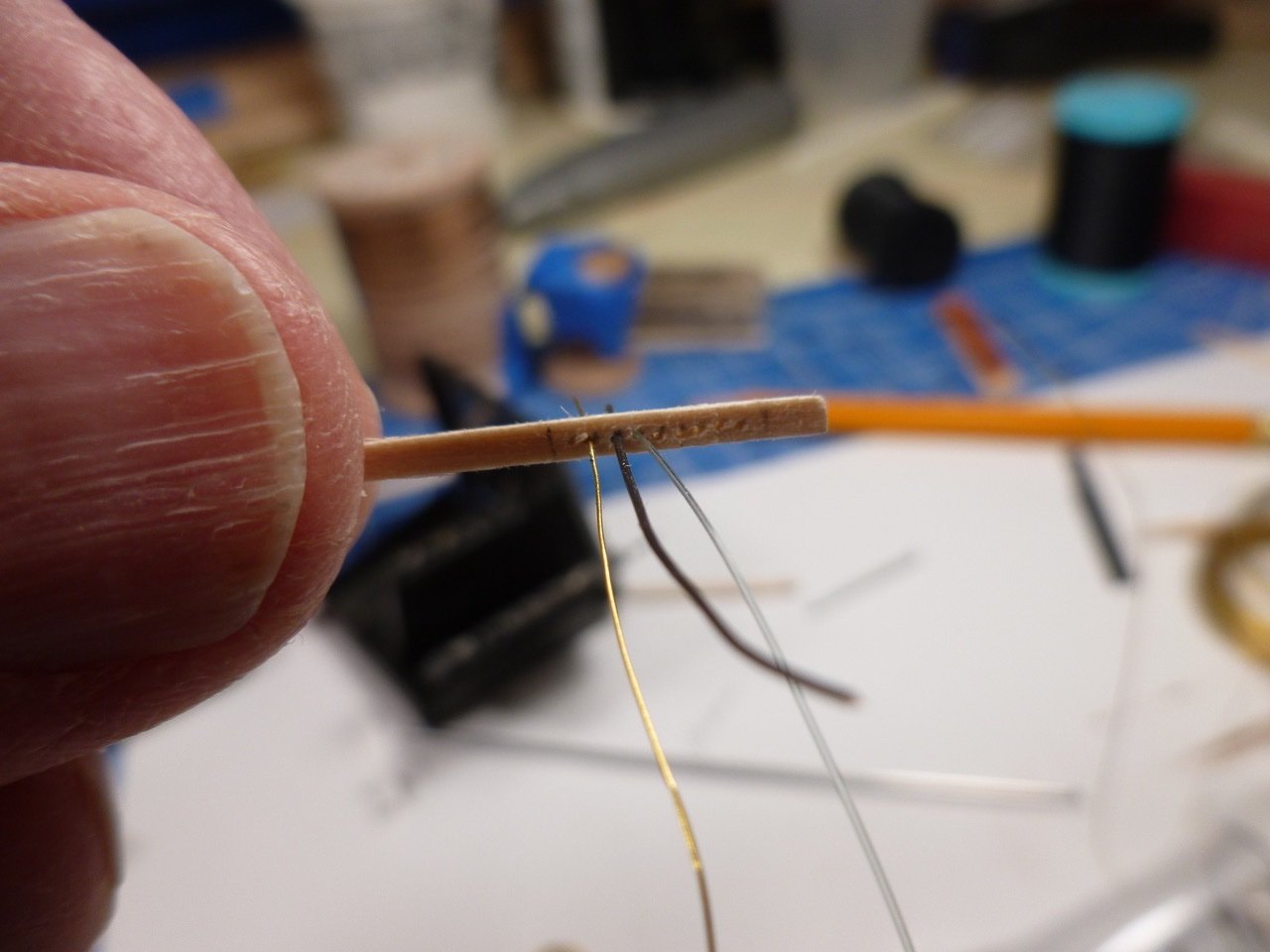
To those who stopped by or gave likes, thank you for your interest and enthusiasm. Rookie, thank you for your kind comments and suggestions, especially your note about 9 versus 8 bars. JJ, thank you for your ongoing participation and feedback. I’ve got another try at the skylight bars that I’m sharing today. I think either way could work. I’m not sure if I’m going to the darkside or the land of courage and enlightenment. I was leaning toward pen lines for bars, and holding off trying real skylight bars after the stacked muntin drilling disaster, and because I had no suitable drill bits. After the bits arrived I realized there might be a workaround to the stacked muntin drilling approach. I cut muntins over length to give some room for tape, then lined them up on a piece of tape using a strip of wood to keep them square. I drew vertical lines across the strips to establish bar spacing, then drew lines that bisected each strip. The crossing points gave the centers for drilling the muntins. This approach would require drilling of each hole (about 240 so far but who’s counting) but would hopefully keep the holes aligned for the bar and muntin assembly. Drilling tools included a sewing needle and ancient hammer for setting center points, and a pin vise with no. 76 bit. I added a bit of tape to the needle for better grip. The 76 bit (73 was my next and way too big) proved to be a very tight fit for the 0.020 bronze rod I had leftover from the Vance build so I poked each finished drill hole with the awl to give a bit more room. I was a “bit” exuberant with one awl poke which split a valuable muntin almost in half but a drop of CA and lots of gentle pressure restored it for use. Initially I included the vertical wood frames for each end in the drilling layout, but quickly realized they would likely split so I removed them from the drilling rotation. To anchor the bars at each end I added more drilled muntins that will be glued to the wood frames. Fortunately I had provided for extra muntins in the layout. Before detaching the muntins I added a colored pencil mark along one end to maintain the orientation during installation on the bars. I also made sure the muntin faces were oriented with the layout sides pointed in the same direction. The idea was to keep the holes in the same orientation vertically and horizontally. Since the muntins are about 1/16 inch deep I’ll have to change the wood frame from 1/32 inch square stock to 1/32 x 1/16. I caved to reality and reduced the bar count to eight. Nine bars (reality) were just too closely spaced for the bronze rod and I had so much of it that I didn’t want to buy a new pack of slightly smaller rod just for the sake of one bar. I think the lightness and transparency of bars will be preferable to nine black ink lines on solid backup. I’m anxious to complete the other bars and the wood framework to see if that proves true. Thanks for viewing. Steve
-
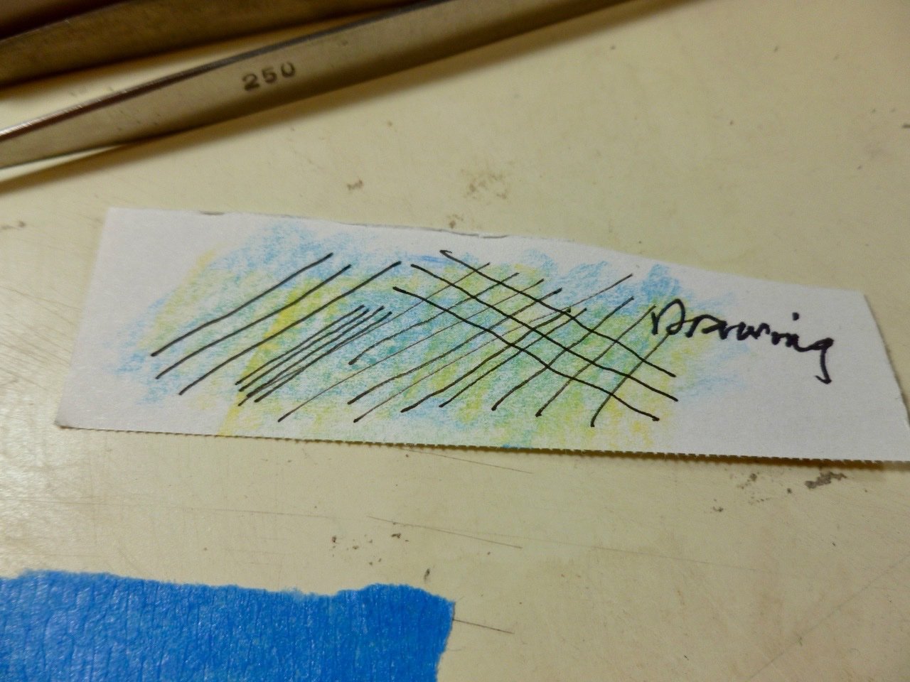
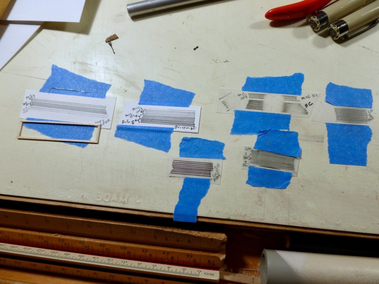
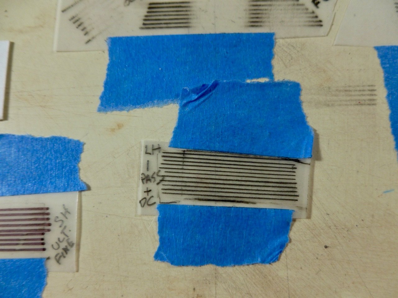
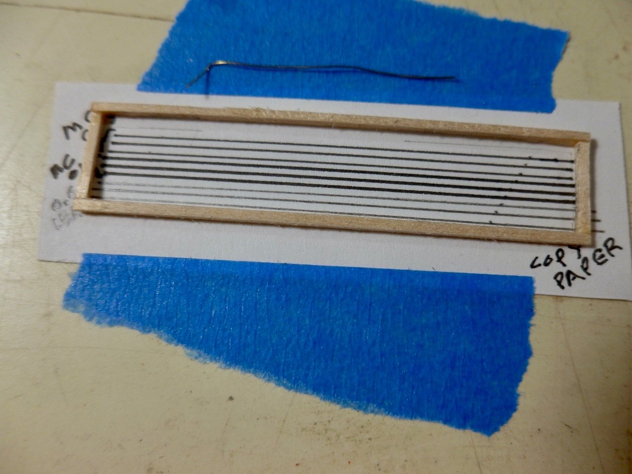
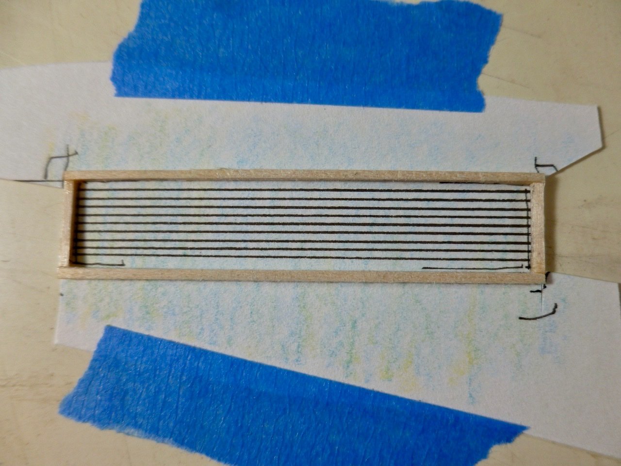
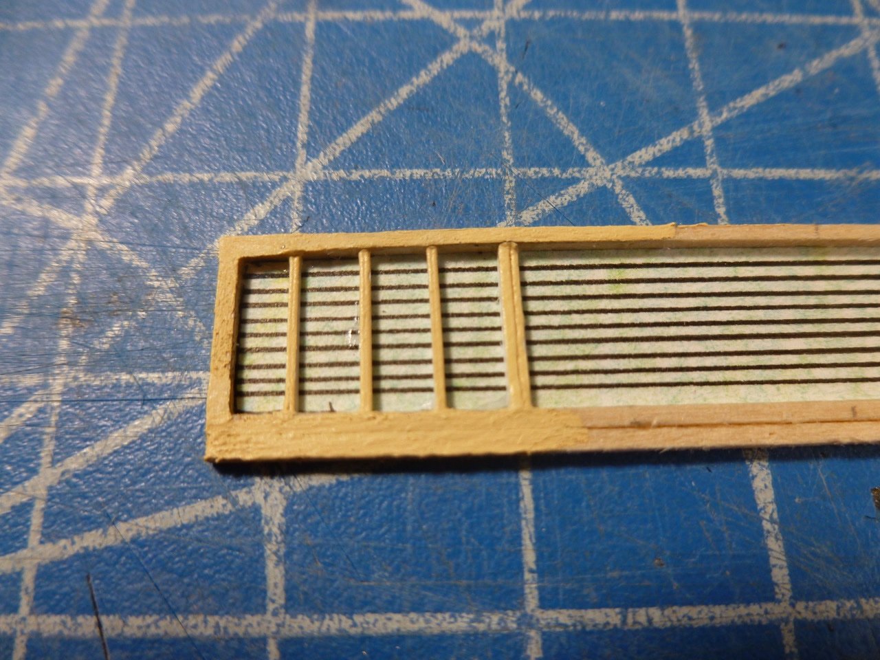
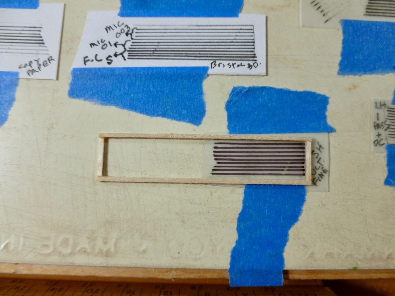
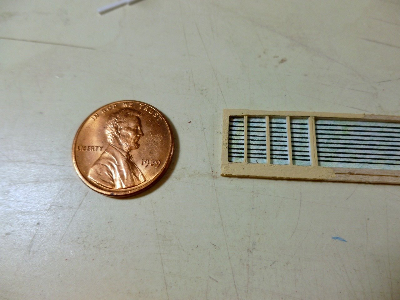
To those who stopped by or gave likes, thank you for your interest and enthusiasm. Waiting on tiny drill bits, but in the meantime I experimented with a skylight roof frame and bars to get a feeling for the scale. The question was whether drawn bars could effectively simulate tiny wire. The issues were what to draw with, what to draw on, what to do for background, and the proper sequence for assembly. The instructions indicate the bar diameter is 0.1 mm. Laughable, at least to me. Less than a pencil width and less than a skinny pen liner. An almost invisible wire. So I dispensed with fantasy and looked for narrow width pen liners, a variety of substrates, and what I had on hand. Tools included pen liners Sakura Micron 01 and 003 and Faber Castell PITT artist size S; an old Sharpie permanent ink Ultrafine, a sharpened wood pencil and a 0.5 size leadholder from my early drafting days. Substrates included clear sheet acetate, polyester drafting film matte one side, standard copy paper, Bristol board, Strathmore 300 series drawing paper and Strathmore 400 series sketch paper. I also grabbed a few Pentel Arts color pencils that we used for adult coloring during Covid, but more on those later. The Sharpie was the only one that stuck to the clear acetate and also to the drafting film. No ruboff, grayish line, a bit fat. The pen liners made skippy lines on the acetate and rubbed off easily even after a half hour drying, and a desperate shot of Dullcote turned them to liquid instantly. Neither pencil nor leadholder could mark the shiny surface. So clear background was a bust. Surprisingly the pen liners also didn’t work on the matte face (the drawing side) of polyester drafting film. This was our go to substrate for architectural hand drawing in the 1970s and 80s. It worked well with leadholders, better if you use “plastic lead” which had a binder in it that helped to prevent the dusting and occasional smearing of standard graphite leads. When we inked drawings, and we did that a lot, we used refillable Koh-i-noor Rapidographs. I don’t recall the ink brand but do remember that we dusted the sheets with pounce bags, which contained a fine powder but whether that was before or after drawing I also don’t recall. The leadholder gave a nice line on the drafting film but with a little dusting from the standard lead which was what I had on hand. The lines were not affected by Dullcote, but the dusting remained. This was a defect for such fine work because the graphite dust tended to obscure the area between lines. The pen liners came into their own on all the papers. Lines were clean and dense, even on the cheap copy paper, but I was concerned about long term durability of the copy paper so that option was tossed. I also canned the Bristol board, not because of appearance which was excellent, but due to the thickness of the sheet which I felt would create problems during assembly. The PITT pen line was a bit too thick so it went too. Below is a comparison of line widths on the copy paper. The top three are the Micron 003, the middle three are the Micron 01 and the bottom three are the 0.5 leadholder. I was down to two papers (the Strathmores) and two Micron pen liners. The 003 size Micron came closest to the 0.1 mm target but in reality was barely visible, even at 0.15 mm. I opted for the size 01 which was more visible at 0.25 mm but still looked in reasonable proportion to the skylight frame. The Strathmore 300 series drawing paper had a very slight edge in cleanliness of line so that made the final cut too. The final line sample is below. The next question was what to do about the background since the total obscurity of white was not desirable and a black background would be, how shall we say it, stupid when paired with black bars. I thought some color might imply a bright interior but when I added color over the ink lines the lines lost some of their pop. Adding color first (blended light blue, medium blue and yellow color pencils) and then drawing the lines was better. I glued the sample to the back of the wood frame using some CA, and added a second 1/32 inch strip along the bottom of the frame since real skylight pics show that part as wider than the head and jambs. Even 1/32 inch was too wide for the muntins (small vertical frames) so I used a 0.060 x 0.020 styrene strip cut in half (0.020 x 0.030) to fit the available frame depth. I globbed on some paint with no surface prep to see how the assembly might look. While doing this I realized the importance of painting the full frame before attaching it to the background. Otherwise the sides of the frame and muntins will either be bare or the paint will schmooze onto the background and bars. The sample photo does not pick up the background colors very well, nor does my eye. I’m thinking the colors may need to be more intense to compete with the closely spaced black lines, or perhaps the background should be a uniform gray. Jury’s out and opinions are welcome. Oh, and here’s the obligatory penny picture.
-
To those who stopped by or gave likes, thank you for your interest. JJ and Srodbro, thanks for the Titebond and CA tips. I’ll give them a try when I receive my stash of size 78 and 80 drill bits. I have some acetate leftover from the Vance build and thought I’d look at two options. First was ink lines using a fine line marker, specifically an ultrafine Sharpie permanent black, and a Faber Castell PITT artist pen superfine. Both required two passes for each line to get a dense black but the Sharpie was a bit fat and the PITT ink rubbed right off. The Sharpie ink bonded well and a new tip (mine has seen considerable use) would likely give a better line, which makes it a possibility. Next test was to try gluing thread directly to the acetate using PVA (white Elmers glue diluted with water). I thought the glue might dry clear, which it did, sort of. Some thread stuck but was relatively easy to dislodge and the glue brush marks were somewhat visible in a grazing light. Maybe a clear craft glue? A primary goal in all this has been to maintain 9 bars on each side at the skylight roof. Fewer bars would make the task easier but I want to see if I’m up to the challenge. Just got a notice that the drill bits have shipped. In the meantime I’ll pick up a new Sharpie and give that a chance. Thanks for viewing. Steve
-
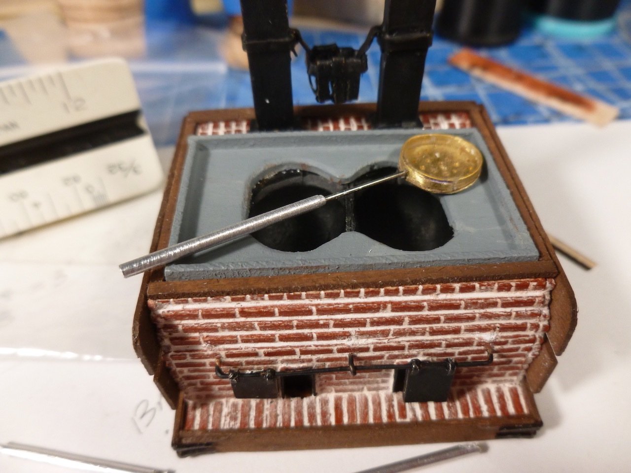
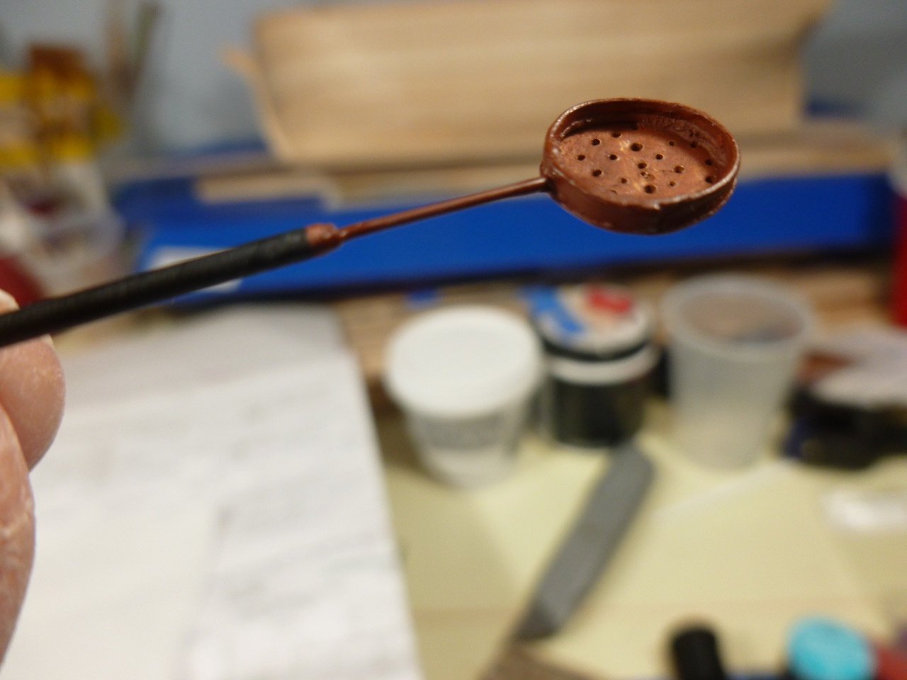
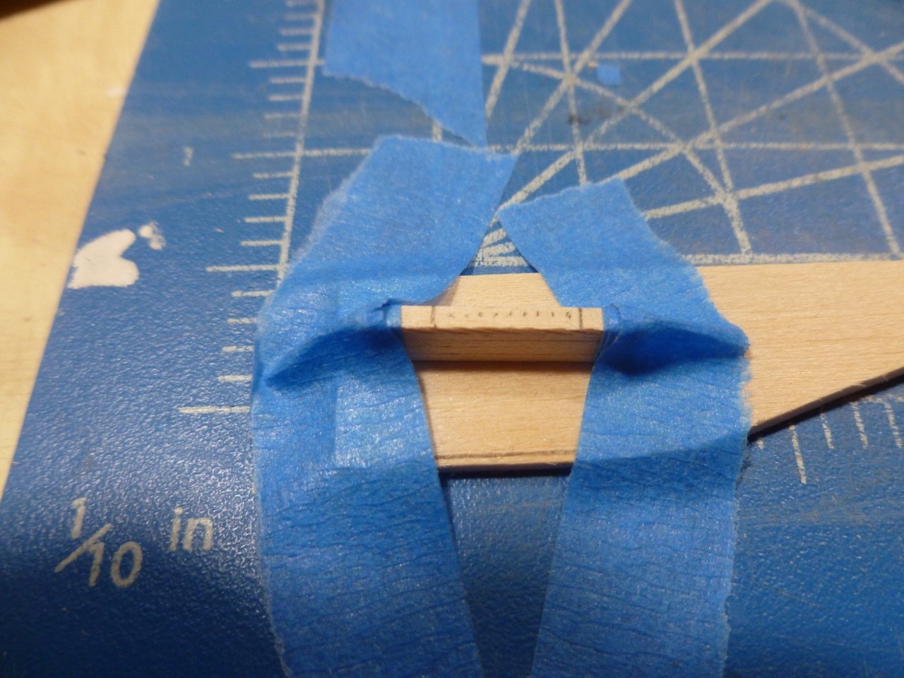
To those who stopped by or gave likes, thank you for your interest and enthusiasm. This was a fun challenge. I believe this is a skimmer for scooping out unwanted stuff from the trypots. The handle is a 1/16” aluminum tube placed in an electric drill and filed to make the outside diameter a bit thinner. A sewing needle slid into the tube forms the forward part. The needle has a bend at the forward end to provide an attachment to the basket which is formed from a brass disk and strip. The holes were made using an awl that my grandmother brought with her from England. Must have been good steel because it punched through the disk with very little effort. The real skimmer had a lot of rust in the forward end and basket so I used rust colored paint, and painted the handle black. As previously noted by many other builders, the skylight glass areas are a corker. My first try was 1/32 inch square basswood, drilled for the bars. A couple of holes and it basically split along the centerline of the holes. Next I tried 1/32 inch x 1/16 inch stock. Held up to the drill a bit better so I experimented with “bars”, including very thin stretched brass wire (not bad but need a smaller drill bit), black annealed steel wire (too fat and can’t stretch it straight like brass) and monofilament fishing line (a bit fat and unsure how to make it straight or whether it takes paint). Another question is how to align the holes. For tiny holes I’m limited to hand drilling with a pin vise. I thought I might try stacking the muntins but on the first try the drill bit, or my eye, or both, got tired and canted so far out of plumb that the bit came out the side of the stack near the bottom. And the wood started to split anyway. And the 1/32 inch face of the muntins looked too fat. So out came the styrene strips I used during the tryworks build. Being monolithic they accept closely spaced drilling better than wood, but the thin strip is quite flexible. It’s a possibility though, and I’ll post the pics, either good or bad, when I get some smaller drill bits. Thanks for viewing. Steve
-
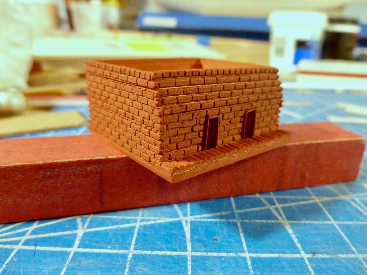
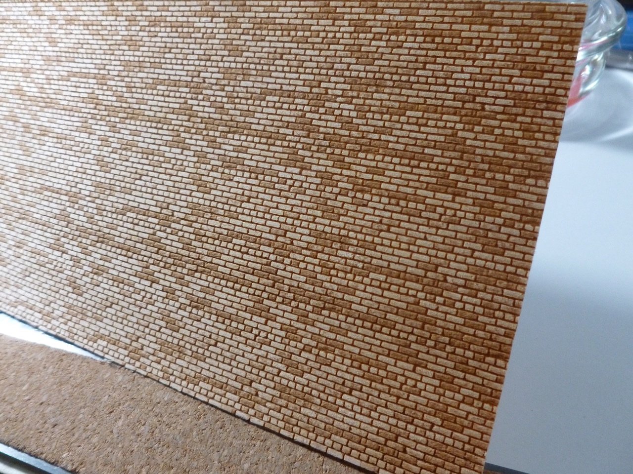
JJ, I'm humbled by your kind words and invigorated by your enthusiasm. Thank you. When you are comparing dimensions to Gerald's instructions please note that using the brick sheets resulted in the top of construction being about 2 millimeters higher. I accepted that difference and worked to keep it by adjusting the number of brick courses, as compared to reality and to Gerald's beautiful handmade bricks.
-
Landlubber Mike, I realized I neglected to recognize your last comment. Thank you for your feedback and your ongoing interest. Steve
-
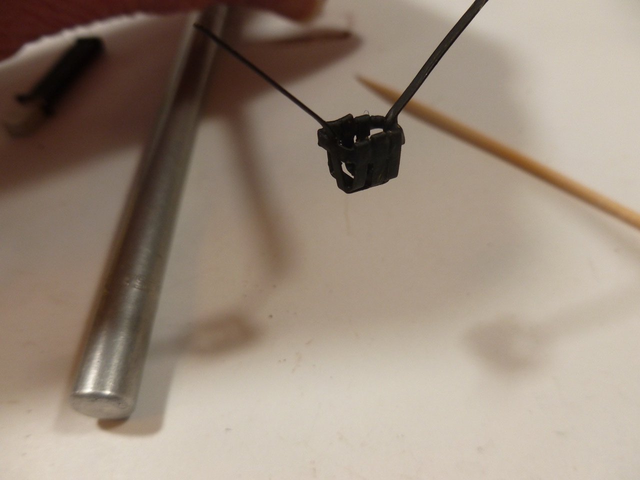
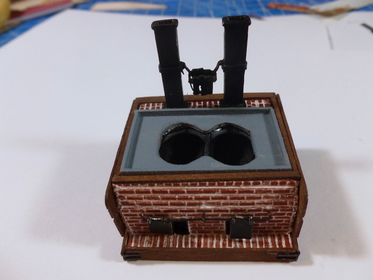
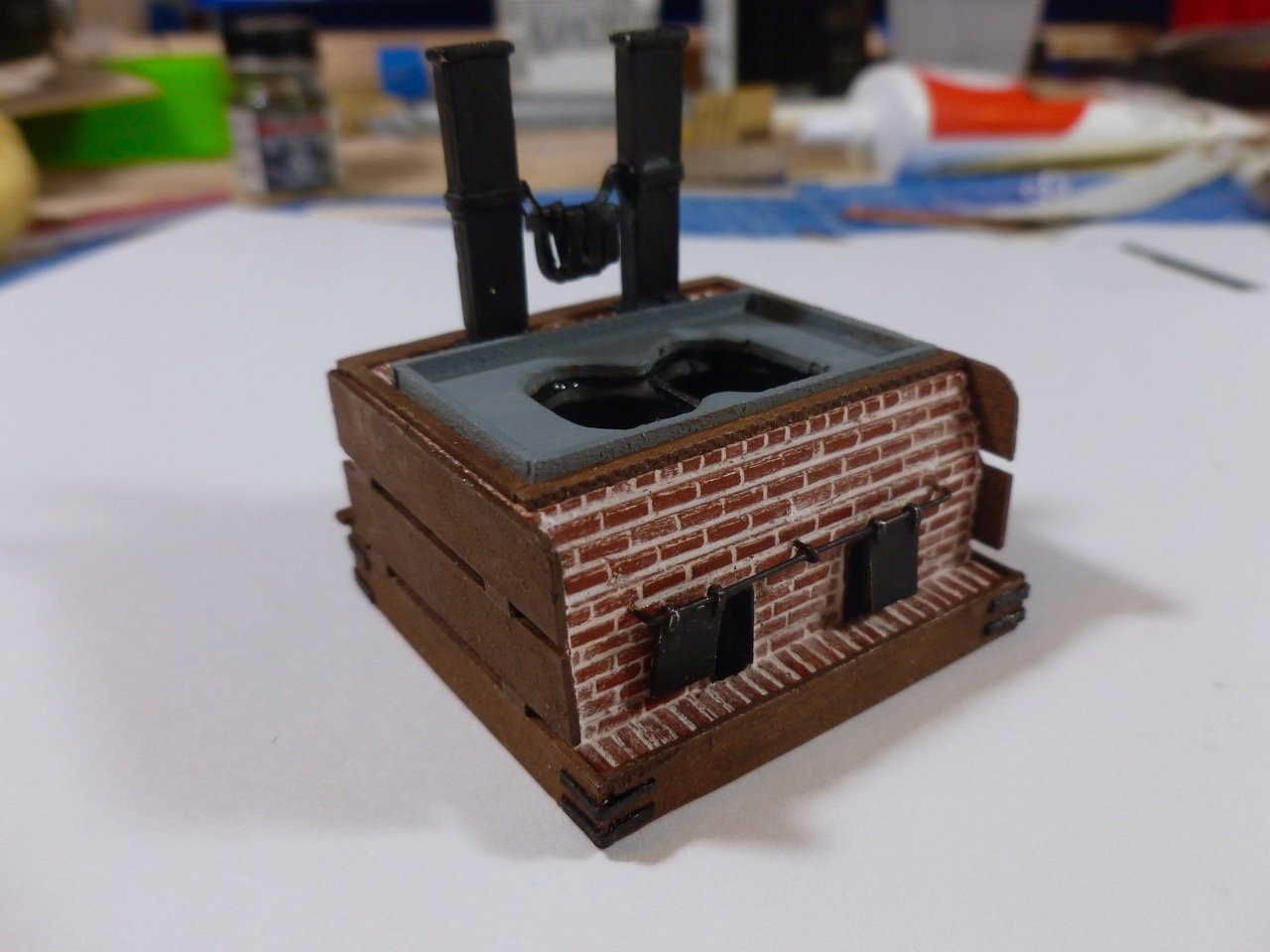
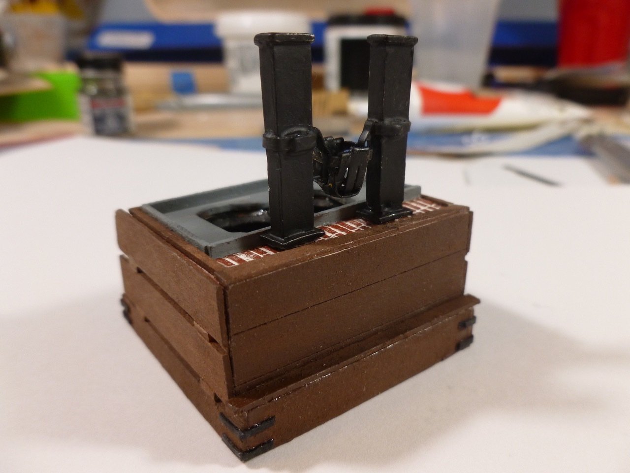
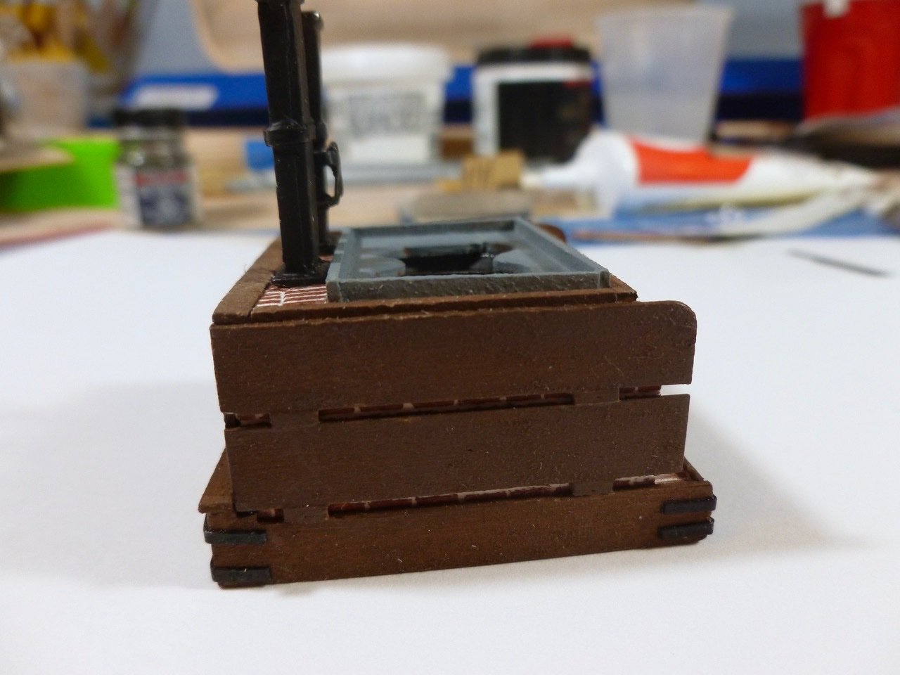
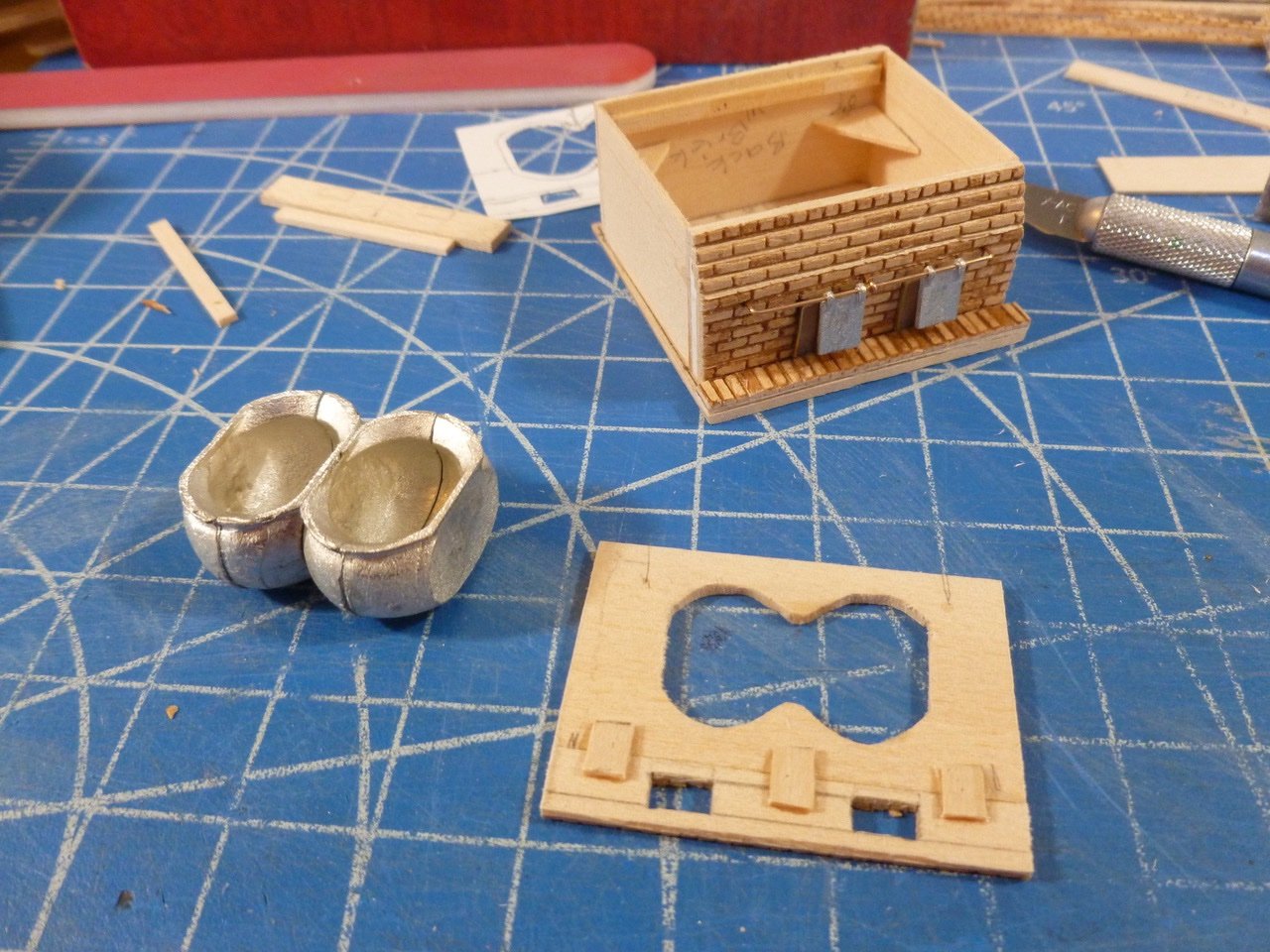
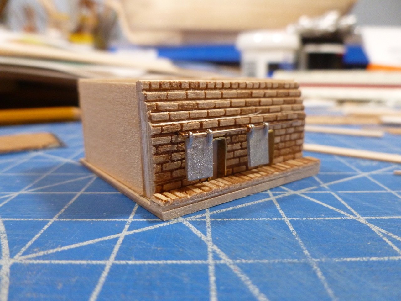
Tryworks continued. To those who stopped by or gave likes, thank you for your interest and enthusiasm. Capt. Kelso, thanks for the photo. I hope I’m doing justice to the real tryworks. Vlax, thank you for your kind words. Before gluing in the cauldron/chimney area panel I test fitted it many times and installed support strips along the front and back inside brick walls. I also added triangle shaped corner braces to hold the brick walls in square. After tracing the cauldrons on the underside of the panel I drew and cut a line inside of the tracing line so the panel opening would align with the inside edge of the cauldron top. The cutting went very quickly with my new jeweler's bench vise and saw with its tiny blade. I fitted the cauldrons to the underside of the panel and beveled the panel around the cauldron edges. This eliminated the problem of the cauldrons falling through the panel. Sounds so perfect, except that after I glued the cauldrons to the panel I forgot to test fit the assembly to the opening. I blithely applied CA to the panel, aligned the back edge, then tilted the panel forward and down. Obstruction! The round bottom of the cauldrons hit the forward corner brackets. Now I had CA setting up at the back and a front that wouldn’t go down. So I pressed harder. Finally I heard a welcoming crunch as the cauldrons broke the corner brackets, allowing the panel to complete its move into place. Once the panel was in place the corner brackets weren’t needed anyway. Note to self: Every time you add something to an assembly, check the clearances again, even if you think it is out of the way. Once the cauldrons were installed and painted I tried simulating some rust which shows up in tryworks photos. Lousy job so I repainted the panel. I’d like to give the panel some character but this isn’t it. I made the basket that hangs between chimneys out of copper strips. Not the greatest but seems okay. Tough to see the individual strips when painted flat black but maybe just as well. The wood side planks were pretty straightforward. The corner plates at the base were made from painted Bristol board, a heavy artist’s paper (the paper is heavy, not the artist). I spaced the bottom of the tryworks brick assembly slightly above the bottom of the wood base to allow for scribing the base to fit the transverse deck curvature. I was musing over how many ducks could fit in the narrow slot of the duck pen under the back wall. Then I discovered a note on the drawings that said the “duck pen” just provides access to a water filled tank under the tryworks to separate the hot cauldron fire box from the ship’s deck. Live and learn, rinse and repeat. The work to date is below. Now I just need a deck on which to place the tryworks. Maybe I’ll try the skylight first. Thanks for viewing. Steve
-
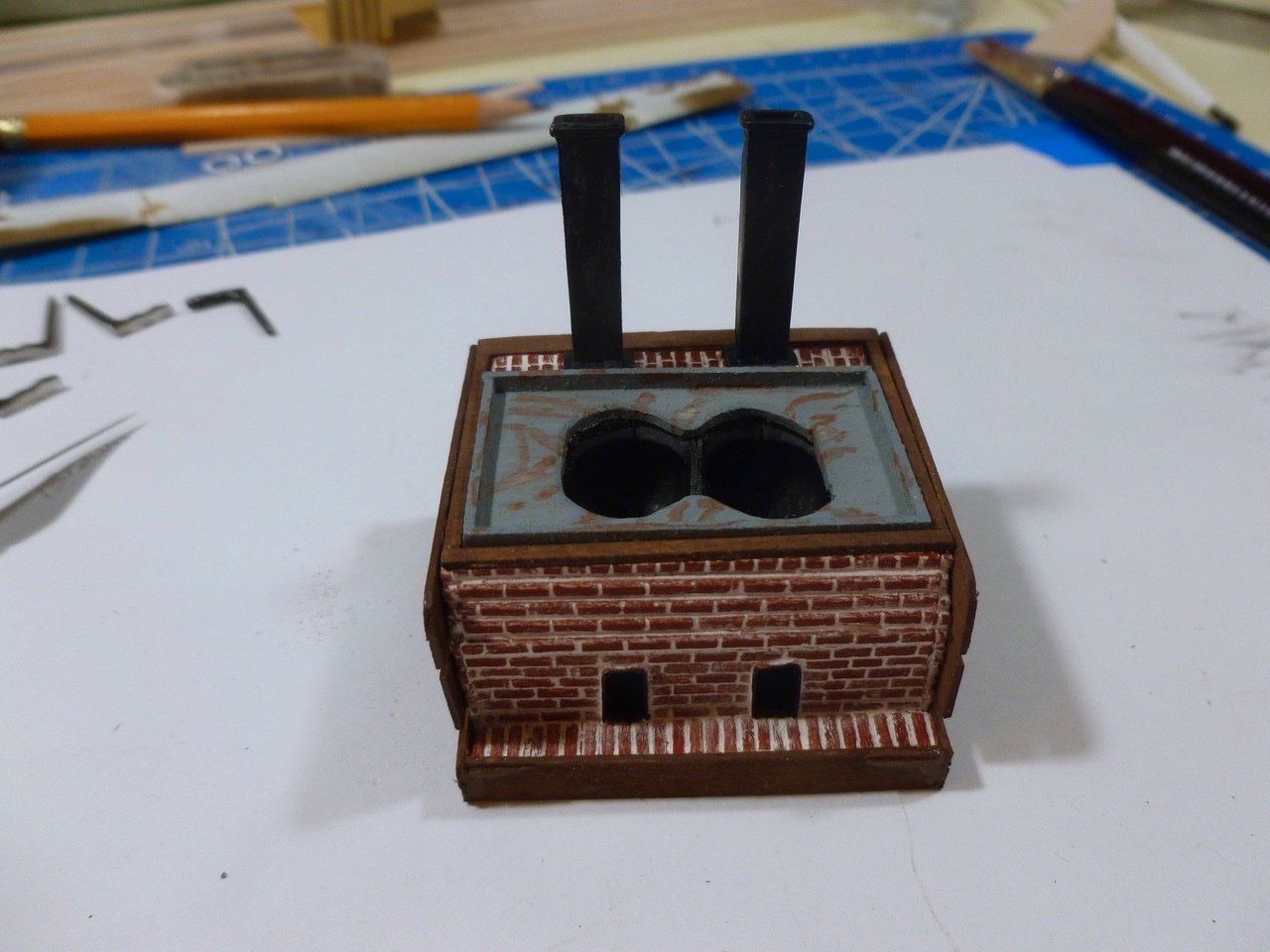
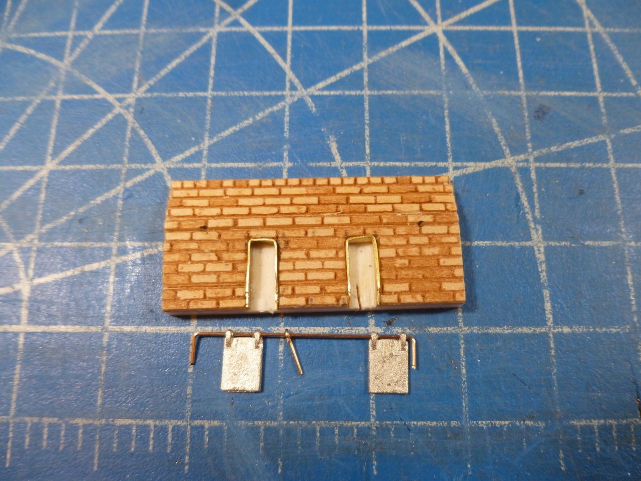
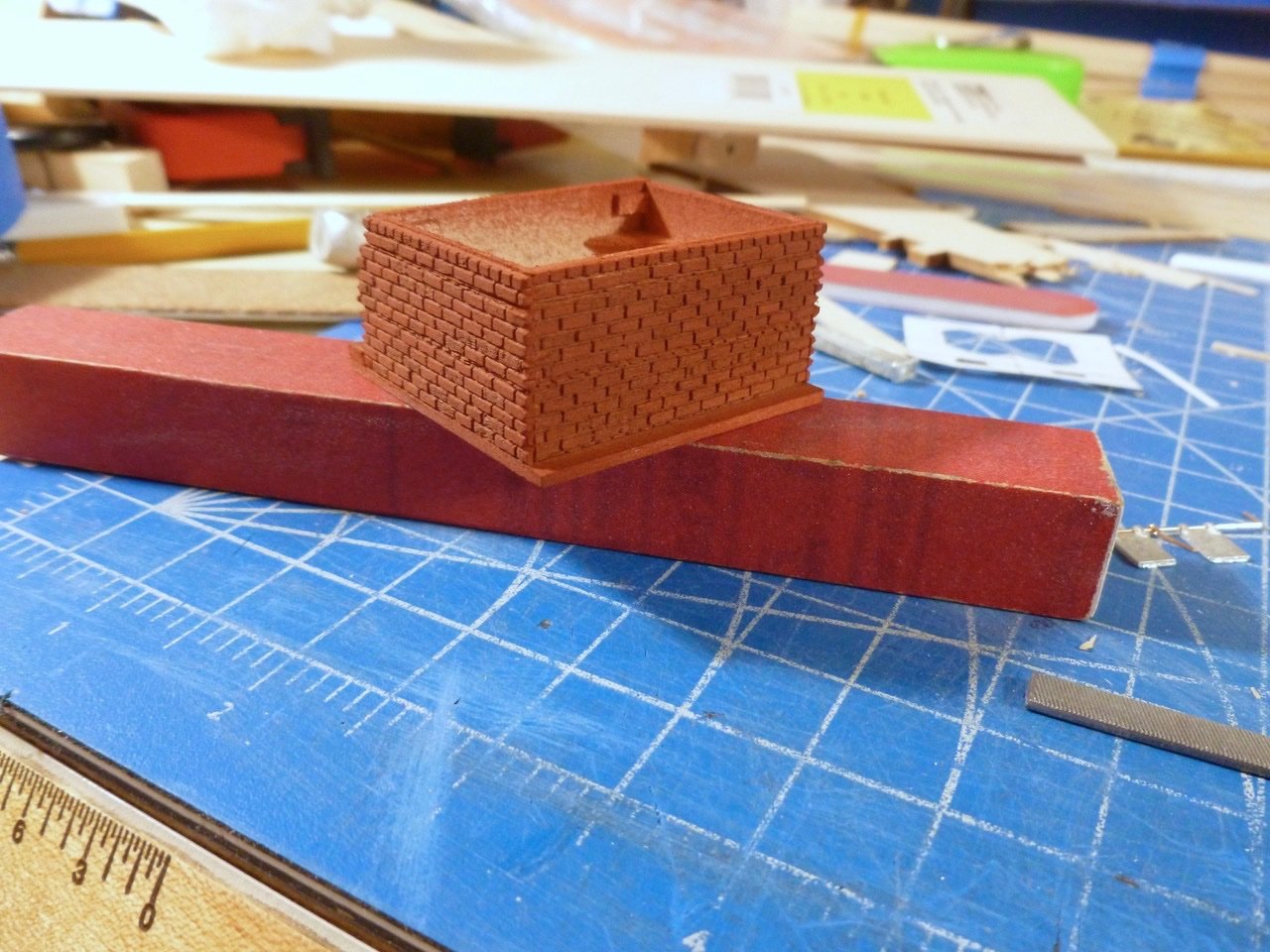
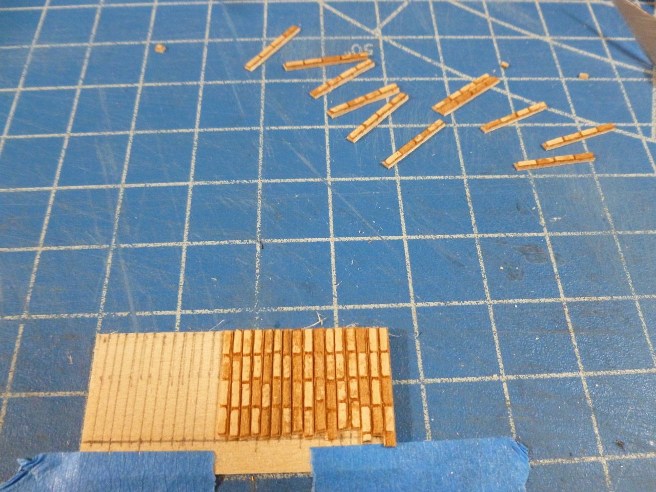
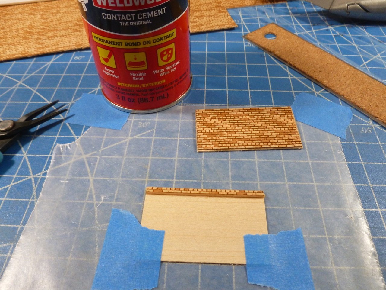
To those who dropped in or gave likes, thank you for your interest and support. It’s amazing how something so small can take so long when you are in scratch mode. First, thank you to Gerald Spargo for his very informative tryworks guide. I can’t hope to match his skill but have tried to be a good follower. After making my brick sample using the laser cut brick sheet I started on the front wall. Two things needed to happen. The brick sheets needed to be sliced to remove the header courses (the row of short brick faces), except for the headers at the top course, because the real tryworks had no headers within the body of the walls. Second, I needed a way to create the stepped appearance at the top of the front wall. Initially I thought that contact cement would be my friend but that only worked where there was a field of bricks in the sheet. CA worked better where I was working with individual courses (rows). After slicing out the header courses I backed up the brick sheet, which is only 1/32 inch thick, with a layer of 1/32 inch basswood. This gave a strong (relatively speaking) composite without too much thickness. I had some strip styrene leftover from the Vance build which was exactly the dimension of one course of bricks. Each thickness of styrene made a brick course step which in the world of masonry is about two inches for corbels (steps). So working from the top down I started with one course using no styrene, the next course with one styrene backup, and then adding a styrene thickness for each successive course. The wall and the section through the wall are below. Now the challenge was to make the side and rear wall coursing approximate the front wall. Not so easy since slicing up the front wall courses introduced some variability between courses on the other walls. I tried several times to fatten up individual courses to effectively make the joints wider. After the angst I realized that the side and rear walls would be hidden behind wood planking. The only brick to be seen on the side was through the gaps between planks. Oh, well it was a fun exercise. Once the front wall was built I cut the door openings. I only went as far as the face of the styrene layer. That layer was quite thick and with the styrene painted black the door opening would have some depth to it. I placed bent copper to form the door jambs and head. One head is a bit wonky but flat black hid a bunch of sins. I used thin brass rod for the door sliders but I haven’t fabricated the brass turn latch between the doors yet. For the front hearth I cut individual bricks. The rear strip between the chimneys is made of two rows of brick so I cut longer strips and pieced them together. Borrowing a tip from Mr. Bluejacket on his tryworks log, I used a rattle can of flat red primer paint and applied one light coat to all the brick. Once that was fully dry I mortared the joints with spackle, then applied a layer of dullcote to all. Before painting the brick I prepped the top panel for the cauldrons and chimney area brick strip. Since the brick was on 1/32 inch backup and the cauldron panel was a full 1/16 inch thick I edge glued the two panels, then added tabs to help support the span. I’m not sure of the maximum upload so I’ll finish up in the next log. Thanks for viewing. Steve

-
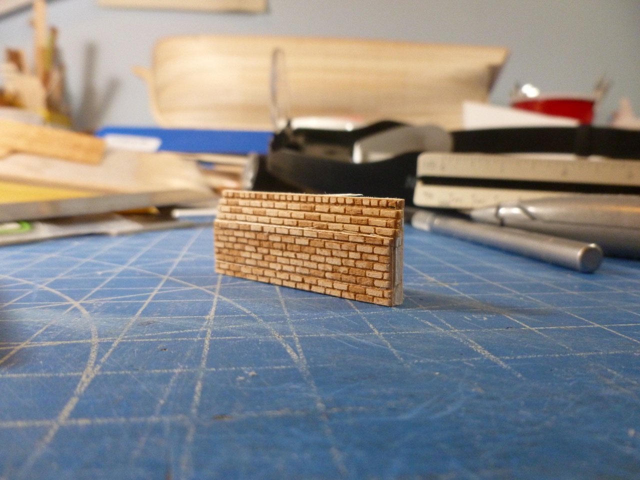
JJ, thanks for your ongoing interest. Very soon I will be posting the work up to the finished tryworks. I used a primer red flat rattle can spray paint from the local hardware store for the final brick color. Below is a sneak peek with no mortar and before the door frames were painted. Thank you Steve
-
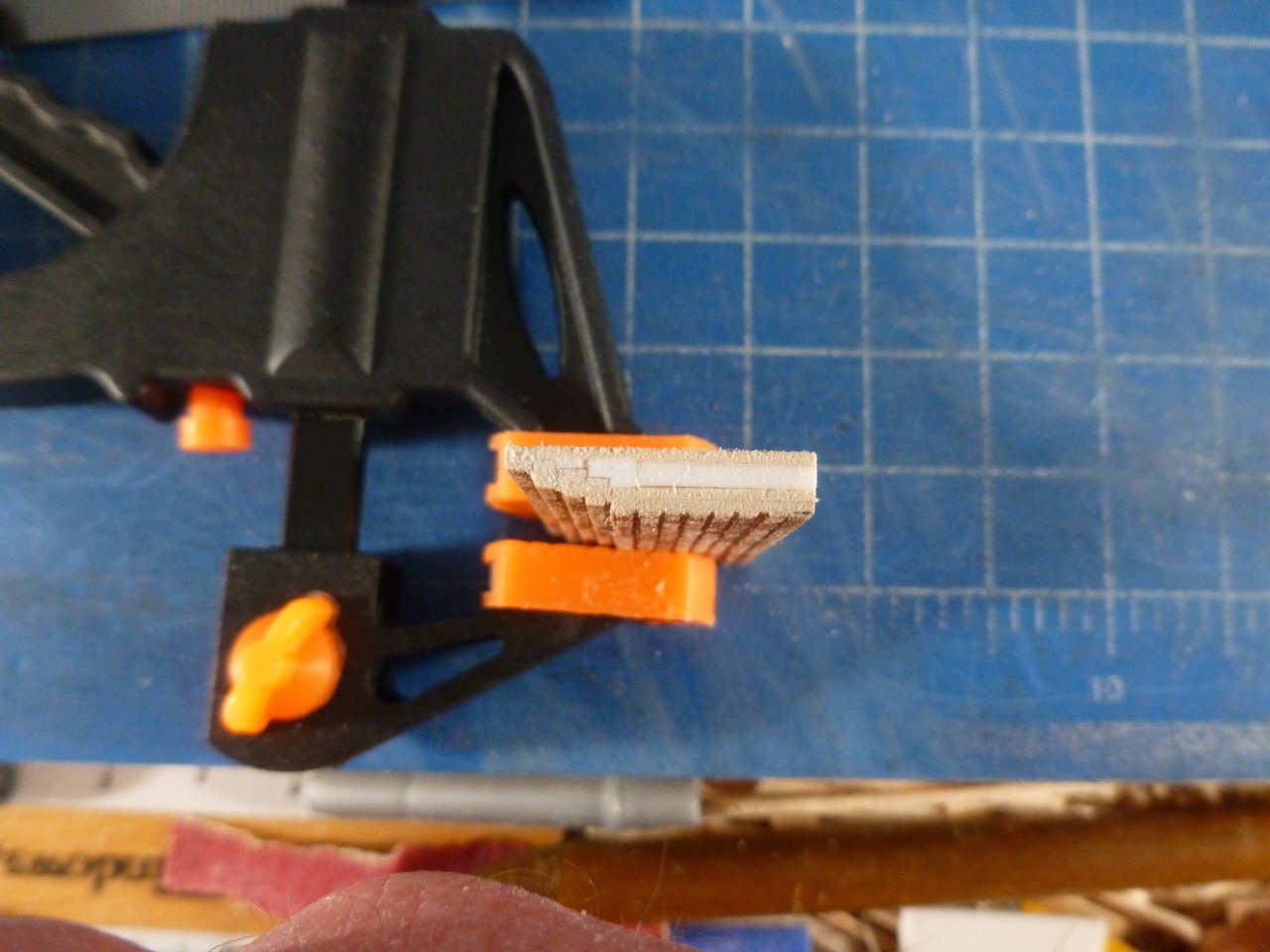
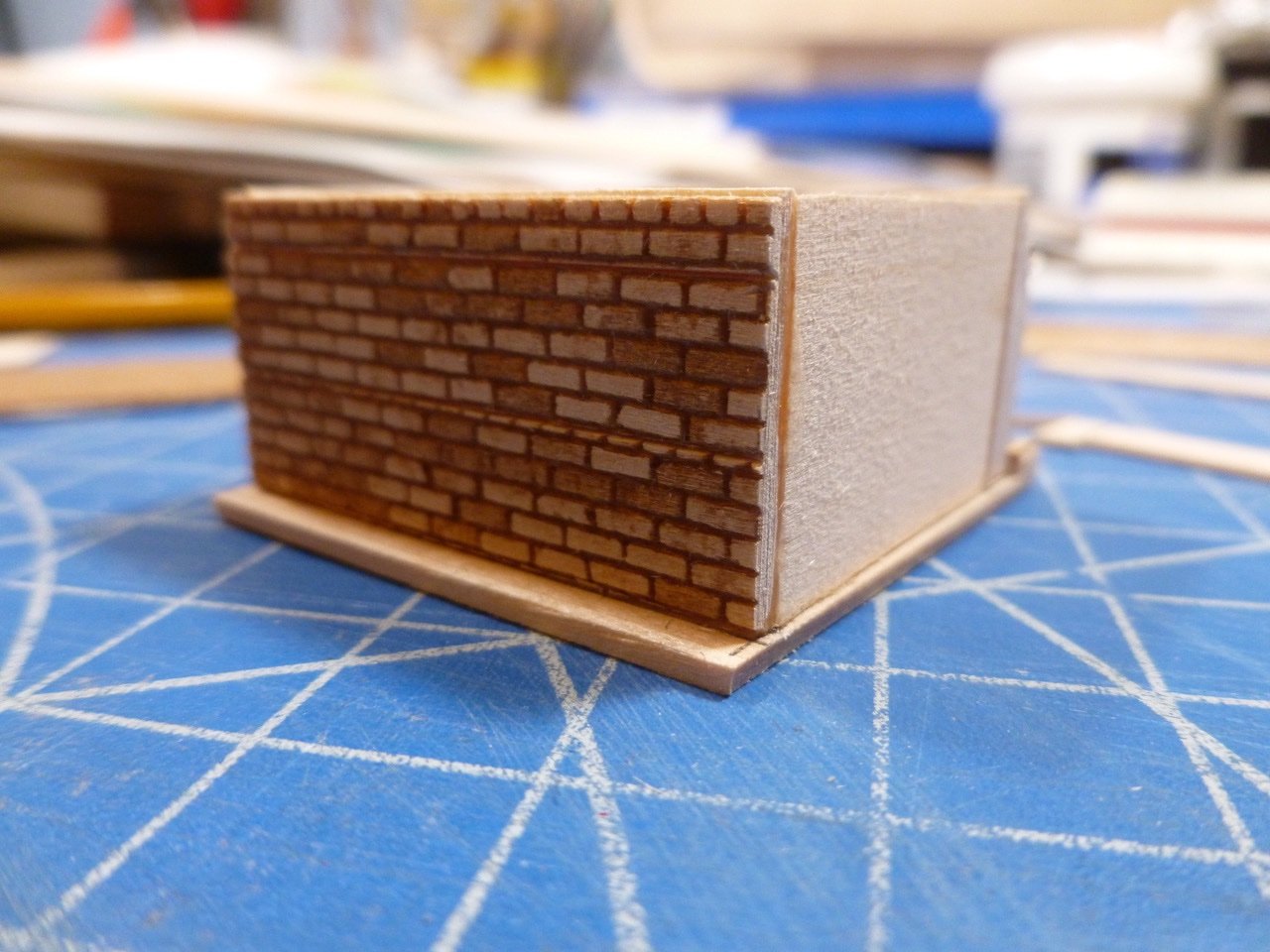
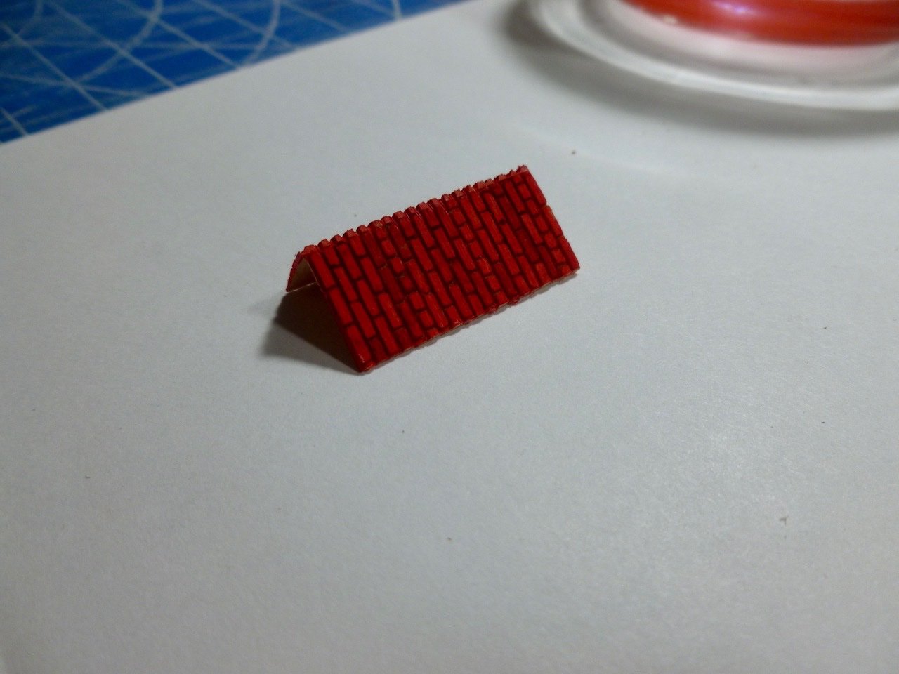
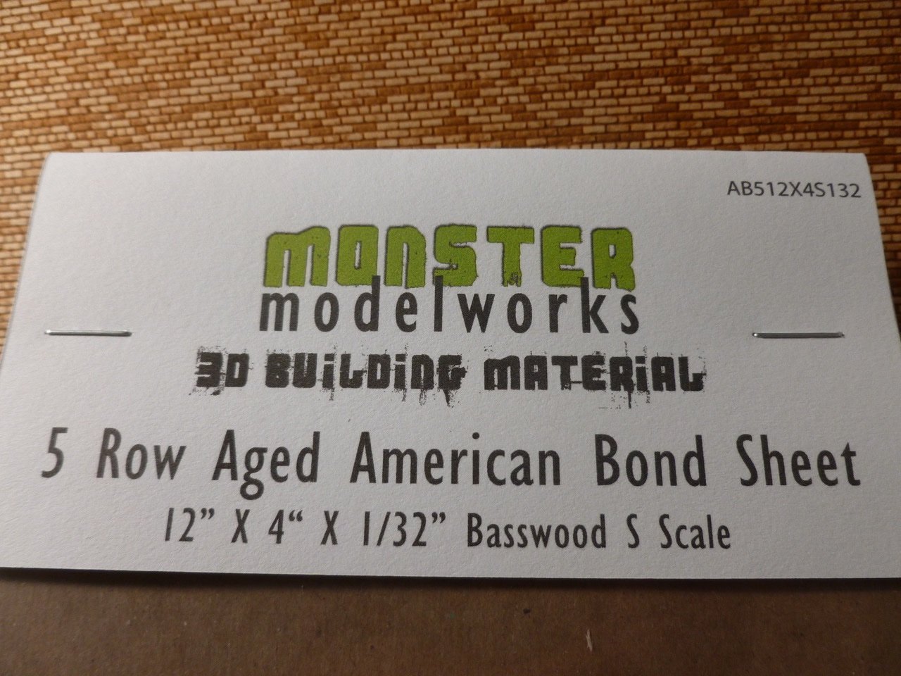
To those who dropped in or gave likes, thank you for your interest and support. Not much accomplished in the shipyard last month. Family get togethers, extended colds with coughs, scratch building a gingerbread house and ship research were all necessary and worthwhile diversions. On the research front I contacted Mystic Seaport to try to better understand why pictures show the red bottom paint at the waterline extending almost up to depth marker 15 at the stern, but only to about 13.5 at the bow. I also asked where the depth markers start, at the bottom of the keel or the bottom of the hull “skin”, which seemed to be an option in some other reference material. The answers I received were that the markers use the bottom of the keel as the zero line and the ship “has drag (deeper aft) by 1.5 feet”, so “the paint line is not parallel to the keel”. Thanks go to Mr. Walter Ansel, Director of the Henry B. duPont Shipyard at Mystic Seaport Museum, for taking time to respond so quickly during the holiday season. Also on the research front I was exploring options for the tryworks brick, other than hand cutting 450 pieces, when I discovered Monster Modelworks at Larkspur Laser Art, which offers a variety of laser cut basswood sheets. One of the sheets I purchased and a sample corner I made up are below. S-Scale (1:64) conveniently matches the ship scale. I filed the joints at the corner line to better represent how the bricks and joints make the turn. I’m waiting for paint to dry before schmoozing spackle or putty into the joints. Seems like a good option, even though I need to slice and dice the sheet to match the real brick installation. I need a better red too. The TV room couch keeps singing its siren song but I'm fighting the urge or I'll never get anything done. Thanks for viewing. Steve
-
Mike, Thanks for your ongoing interest and feedback. I agree that the higher line in copper looks good. I'm just not up to placing all those plates, especially with all the 1/32" overlaps and fastener imprinting, but I admire the discipline of you and others who have accepted the challenge. I wish you best of luck with oxidizing or painting the plates and I'm sure with your skills it will come out great no matter what you choose. I think the high line in red paint may be too much so once I figure out where the low line should be I plan on using that for top of paint. The photos and videos of the renovated Morgan are a no brainer if I can figure out whether Mystic used the bottom of keel or bottom of hull skin (rabbet line?) as the starting point for the depth markers. I'm fighting a cold so not much going on in the shipyard at the moment. I also have a gingerbread house on the to-do list. Steve
-
To those who dropped in or gave likes, thank you for your ongoing interest and support. Mike, I appreciate your kind words and enthusiasm. Question for hardy sailors: I'm trying to determine where the red hull paint should start. Videos of the Morgan post-renovation show the stem painting at draft mark 13 (feet) and the stern at almost 15 feet. The question is measured from what? The Coast Guard draft mark definition includes a comment that the starting line is the bottom of the "hull skin" but clarifies that the starting point may be the bottom of the keel where the hull skin cannot be reasonably determined. The reference line (waterline?) on the drawing measures about 14'-1" from the bottom of the keel rabbet (hull skin?)near the bow (bulkhead C) and near the stern (bulkhead O). Both measurements increase to about 16 feet if the starting point is the bottom of keel. On the copper plating drawing the measurement from bottom of keel to top of plating is 13'-8" at bulkhead C and 15'-0" at bulkhead O. Several of the side view detail drawings make reference to a 16 foot waterline which seems to correspond to the reference line if the starting point is the bottom of keel but this doesn't seem to coordinate with the as-sailed condition. I welcome any feedback. Thanks Steve
