ESF
-
Posts
381 -
Joined
-
Last visited
Content Type
Profiles
Forums
Gallery
Events
Everything posted by ESF
-
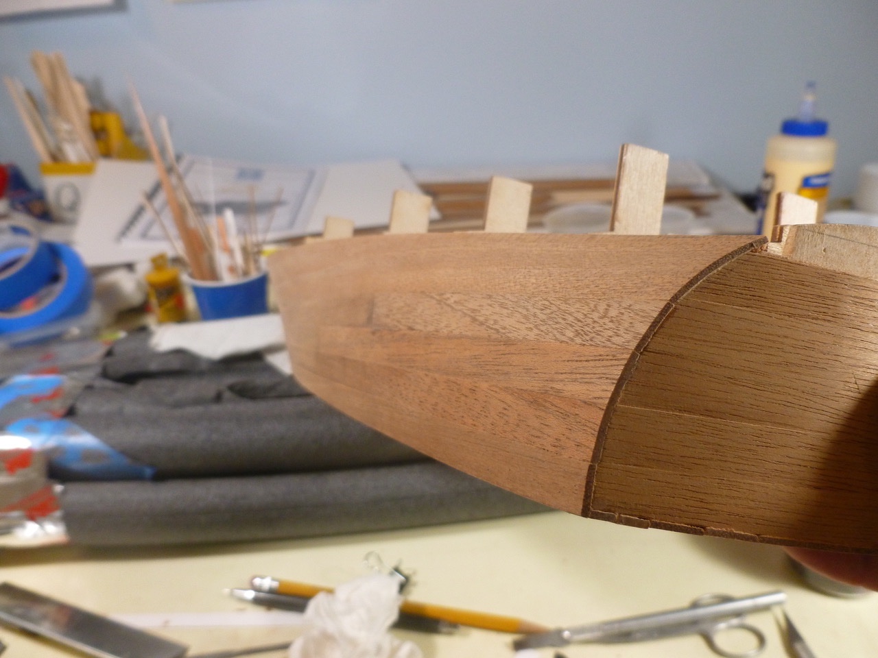
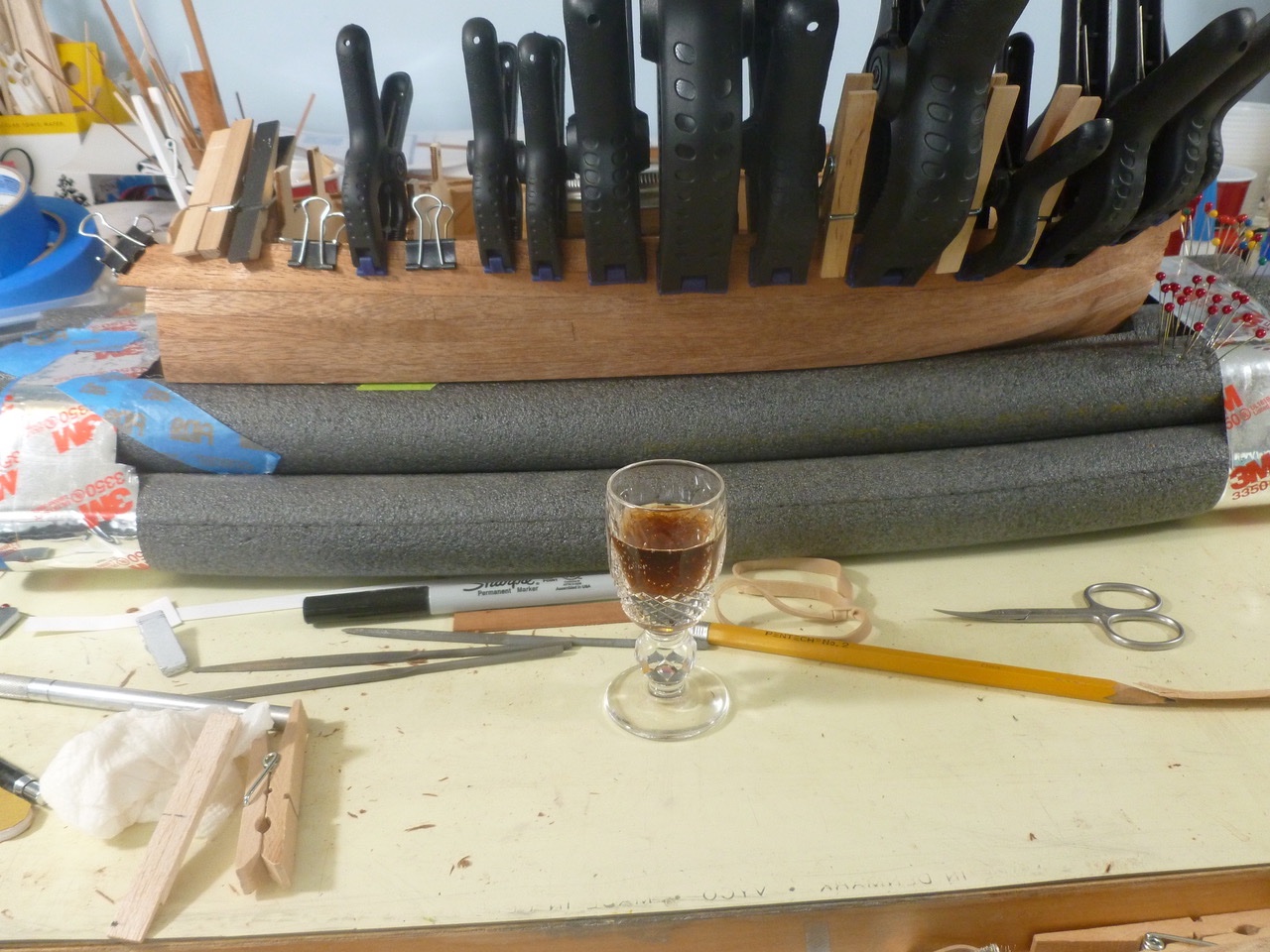
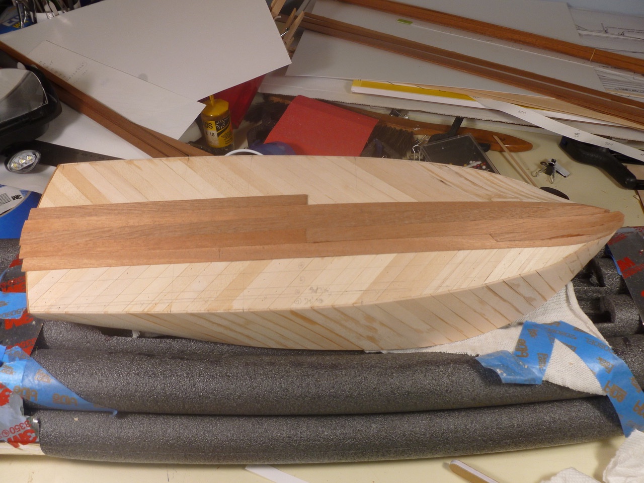
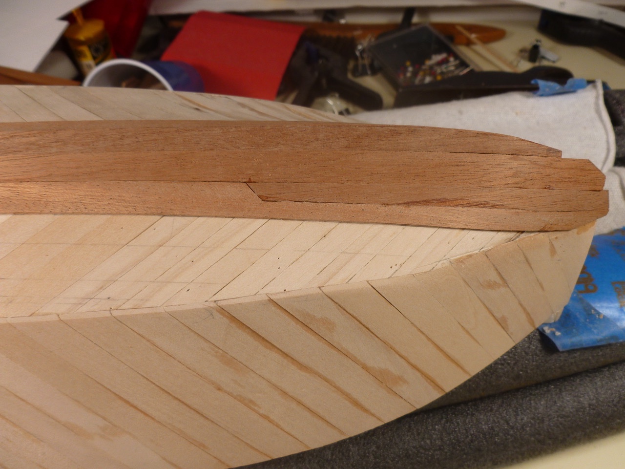
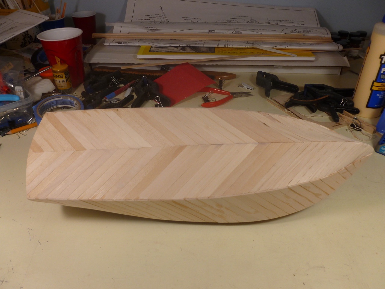
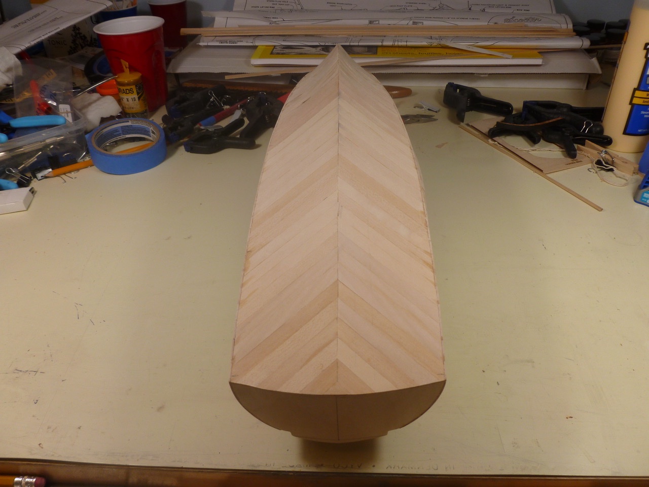
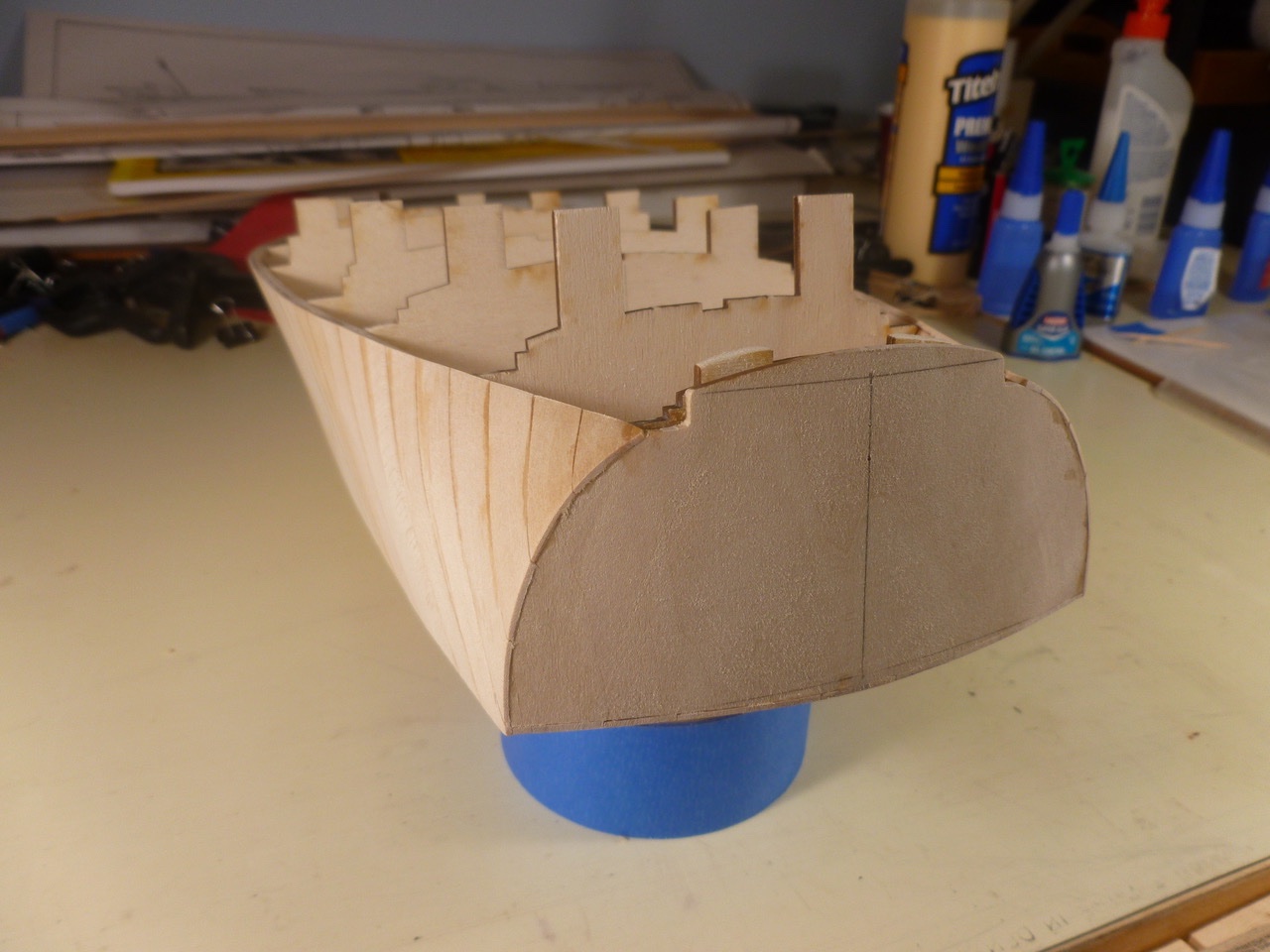
 To those who dropped in or gave likes, thank you for your interest and support. The whiskey plank installation was a time for celebration with an almost scale sized glass filled from the Admiral’s private store of caffeine free diet soda. A few small open joints were filled with a mixture of Titebond II and mahogany sawdust, pressed in with a finger and immediately sanded. Hope this doesn’t disqualify me from my goal of building with no filler. The forward planking managed the transition from a sharp chine to a smoothly blended bow. In the interest of brevity only the port planking is shown but the starboard is the same in fit and sanding. The side planking is reasonably aligned with the transom and thank goodness the joints are pretty tight. Final sanding is being withheld pending installation of the port and starboard covering boards (actually half inch thick blocks but more on that later). Thanks for viewing. Steve
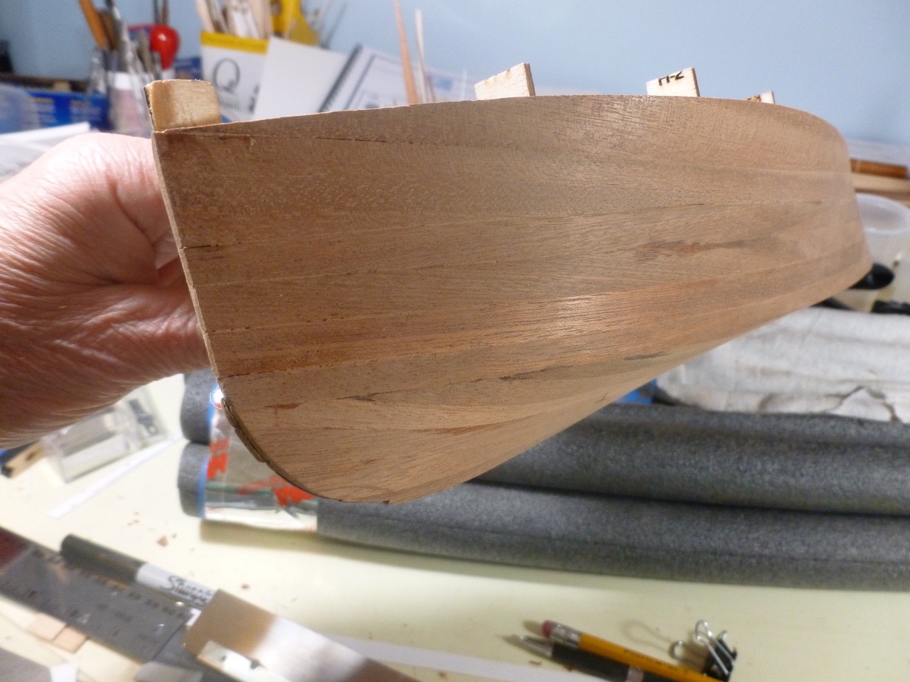
- 40 replies
-
- 6
-

-
- BlueJacket Shipcrafters
- Chris-Craft
- (and 2 more)
-
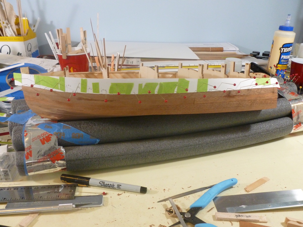
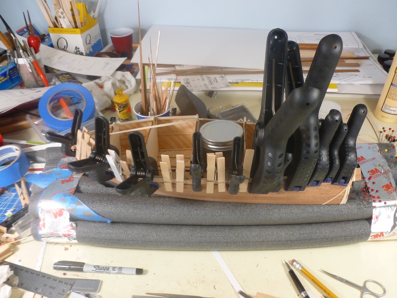
To those who dropped in or gave likes, thank you for your interest and support. The side templates were next. The side plank at the chine looked simple to start (as shown), but ended up requiring much massaging to blend with the hull planks, not only of the plank itself but also the underlying inner planks to ensure a solid base. My obsession and trepidation with this part of the build will probably seem humorous, and more like child’s play, to those who have completed far more complex geometry on bluff bowed ships. I have a renewed appreciation for all who attempt and succeed at such projects. Side plank clamping was aided by the inner planking, and in some cases hindered when previously installed items got in the way. The glass jar amidships is full of steel shot. It was used as ballast for the Zebulon B. Vance RC sailing, prior to the current assignment of holding the Chris Craft in place. The top two strakes on each side were worked in pairs to follow the compound curvature while remaining within the dimensions of the existing planks. Below is a finished example. Thanks for viewing. Steve
- 40 replies
-
- 5
-
-
- BlueJacket Shipcrafters
- Chris-Craft
- (and 2 more)
-
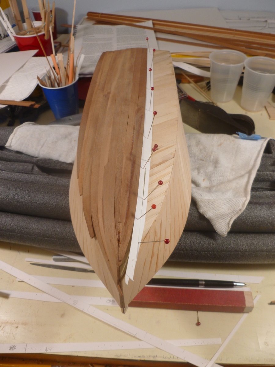
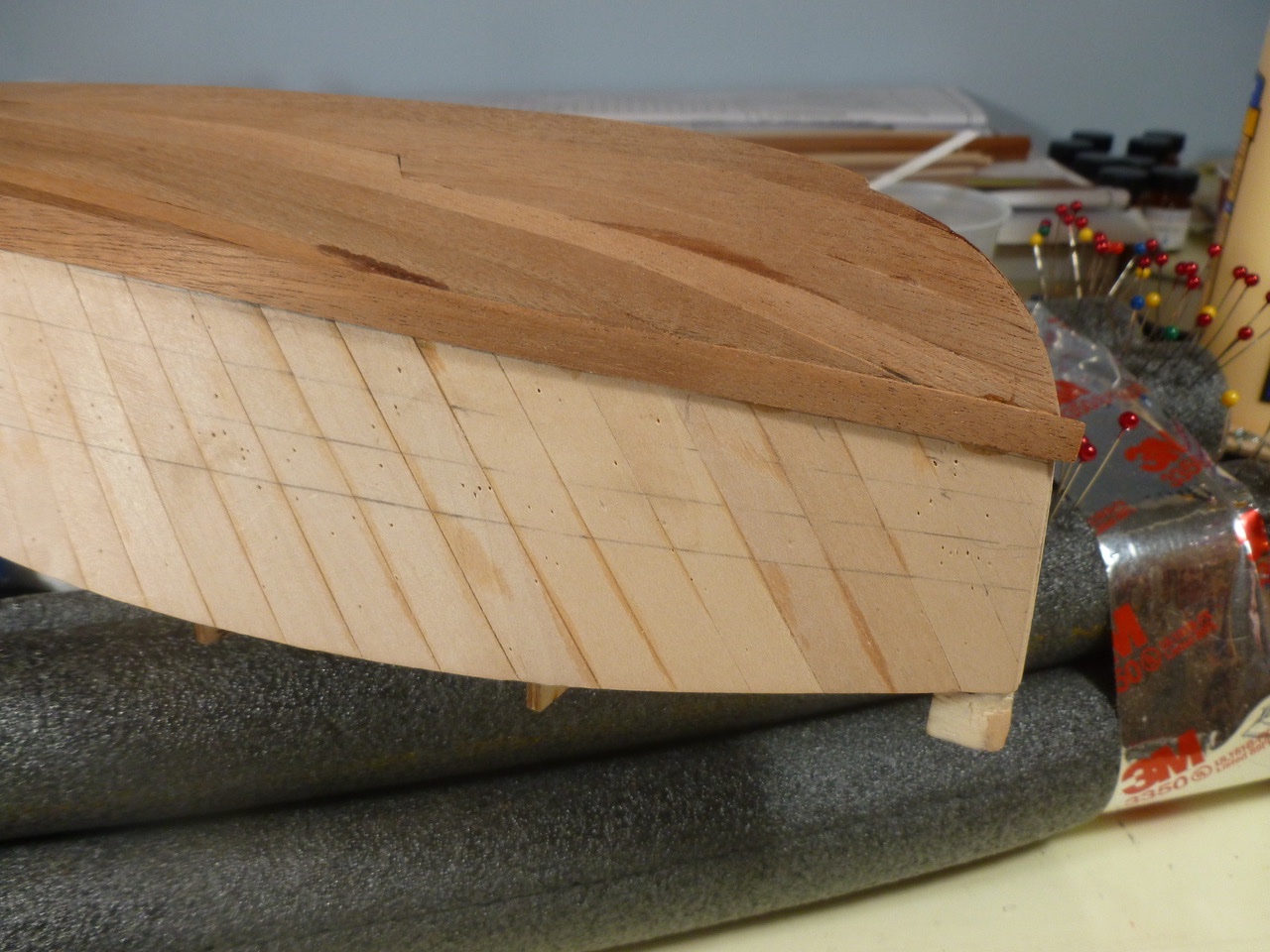
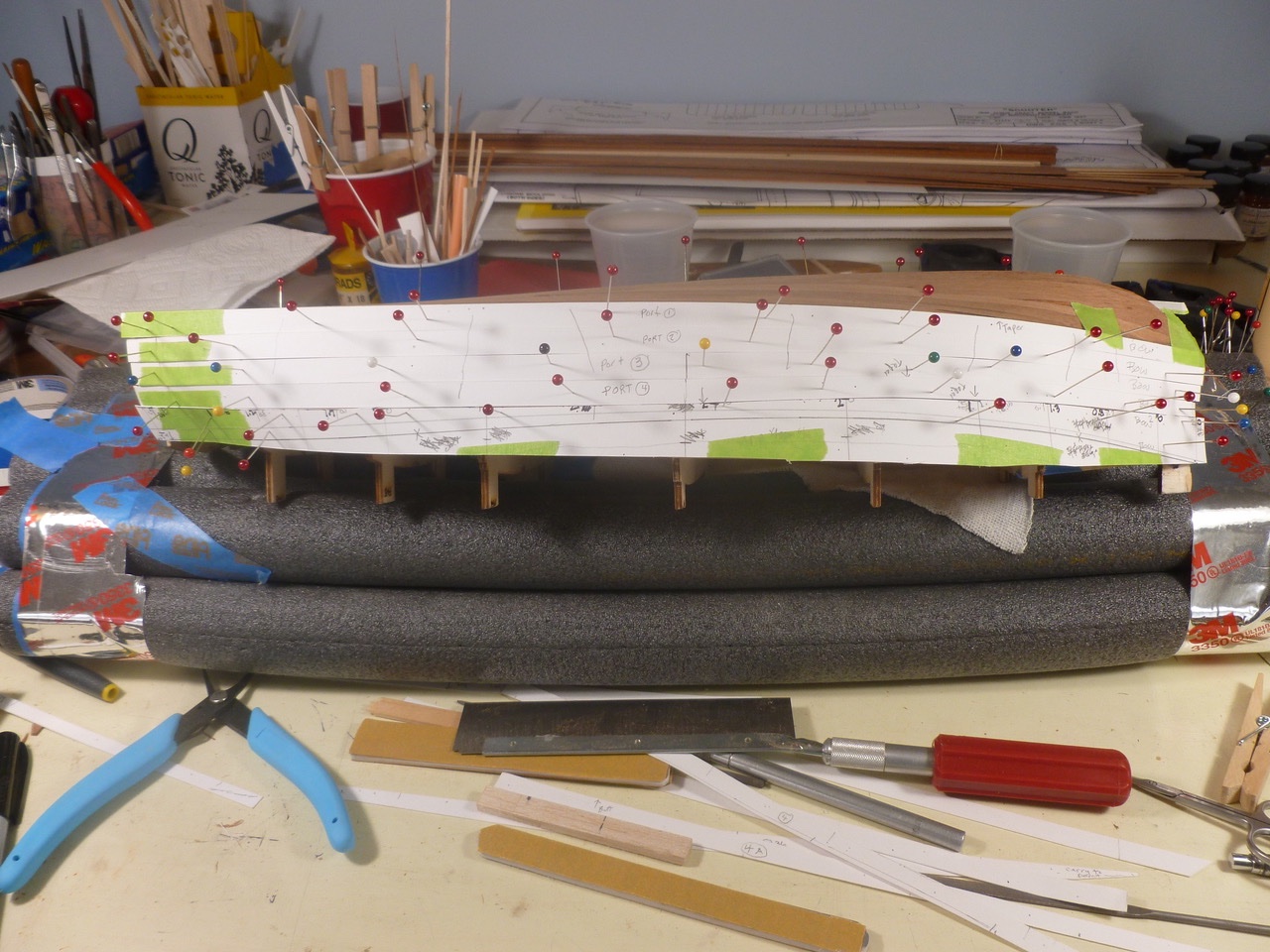
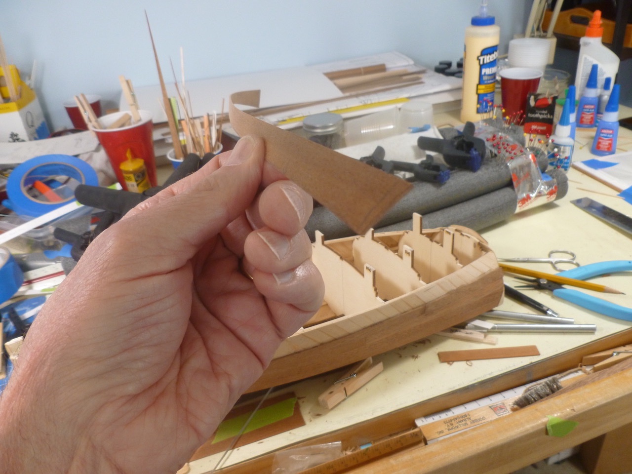
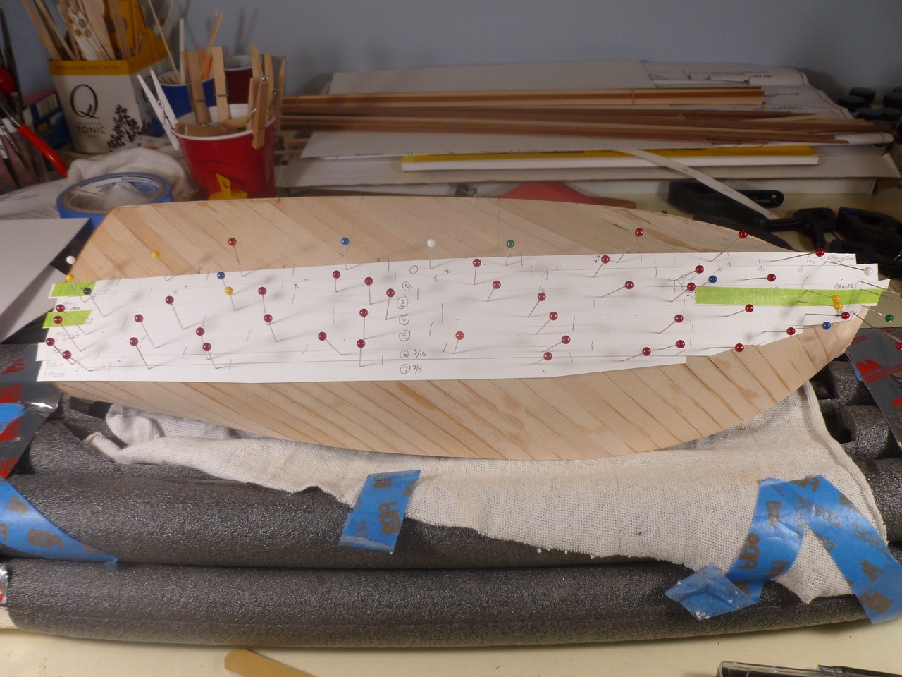
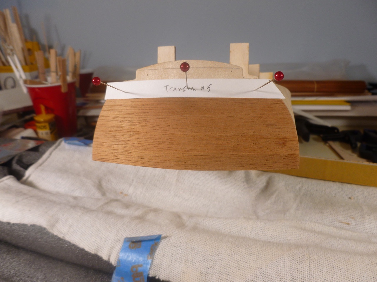
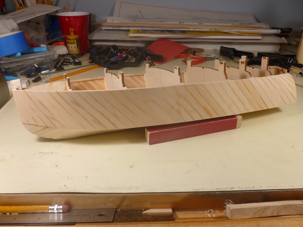
To those who dropped in or gave likes, thank you for your interest and support. In the spirit of baby steps the first outer planks were placed at the transom. Deceptive little devils. Each one required a drop of water and gentle ironing to conform to the inner transom curve, adding to my anxiety at the effort that will be required for the remaining planking. The top transom planking will be installed later, after the hull and deck planking are set. Apparently the orientation of the transom-to-deck planking joint is opposite the orientation of the transom-to-side and bottom joints. Having never built a double planked hull, and knowing that there will be little tolerance for poor plank shape in a bright finish hull, it was pleasantly surprising to realize I could template each plank with Bristol board (stiff art paper) pinned to the inner planks. I made most of my mistakes at that level before tracing the final shapes on the mahogany strips. Per the instructions, the hull planking starts at the keel, using a strip beveled along the keel edge for a close fit with its neighbor. Since the hull and side are curved, the remaining planks must be beveled along one edge for a tight fit. A slight wobble that originated in part of the keel created opportunities for unwanted adjustments in both the inner and outer planking along the keel line. One bottom plank stealer was needed near the bow to ensure adequate plank widths at the stem. As the planking neared the chine it became apparent that the joint between bottom and side planking must transition from a sharp edge to a smooth blend as it approaches the bow. Thanks for viewing. Steve

- 40 replies
-
- 7
-
-
- BlueJacket Shipcrafters
- Chris-Craft
- (and 2 more)
-
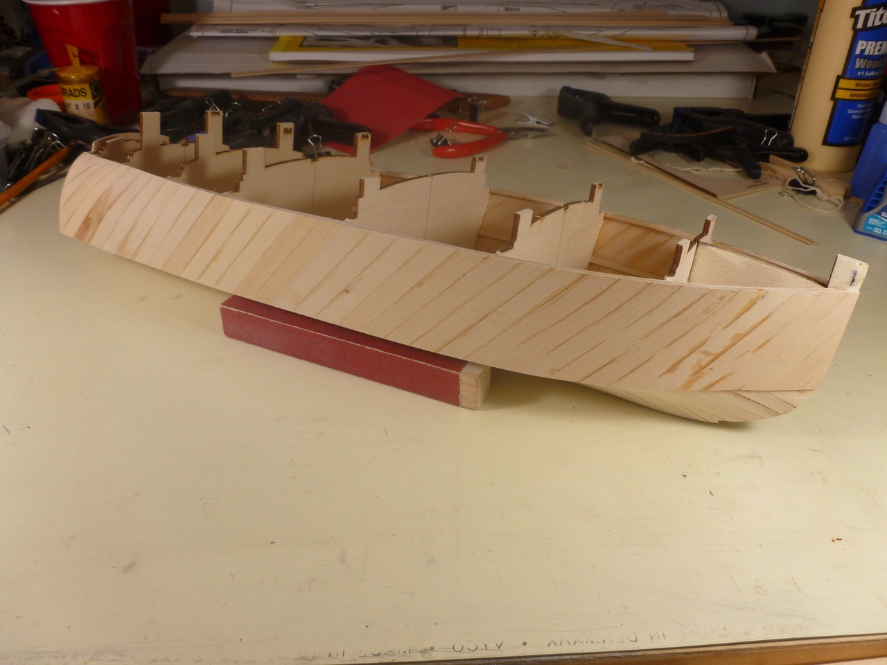
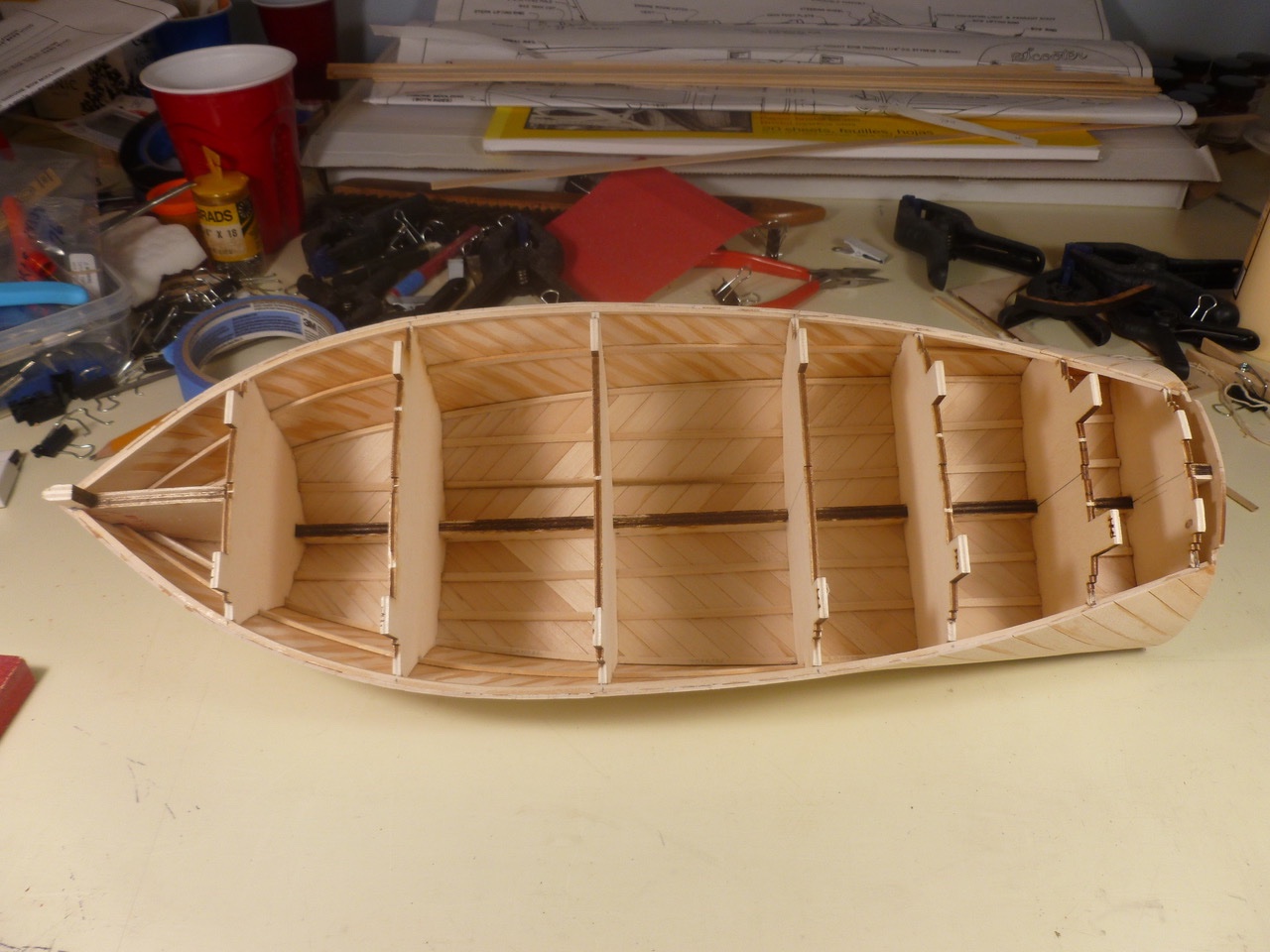
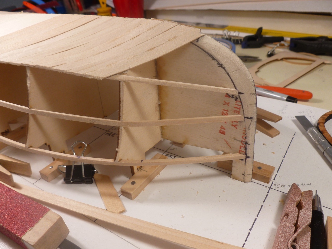
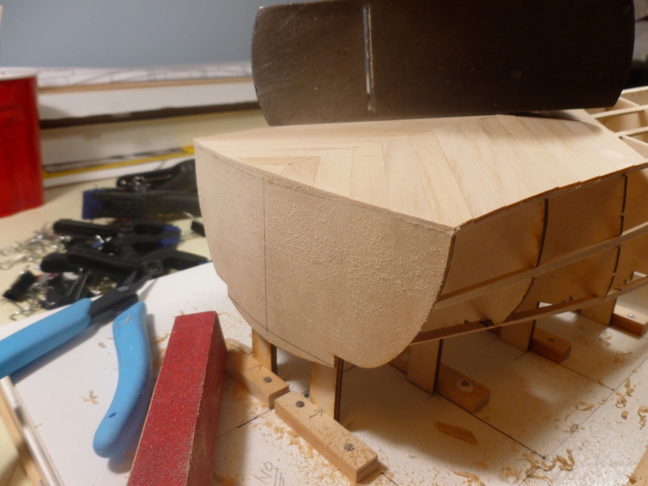
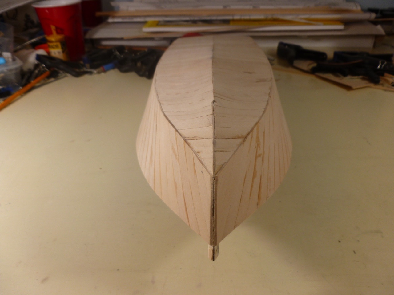
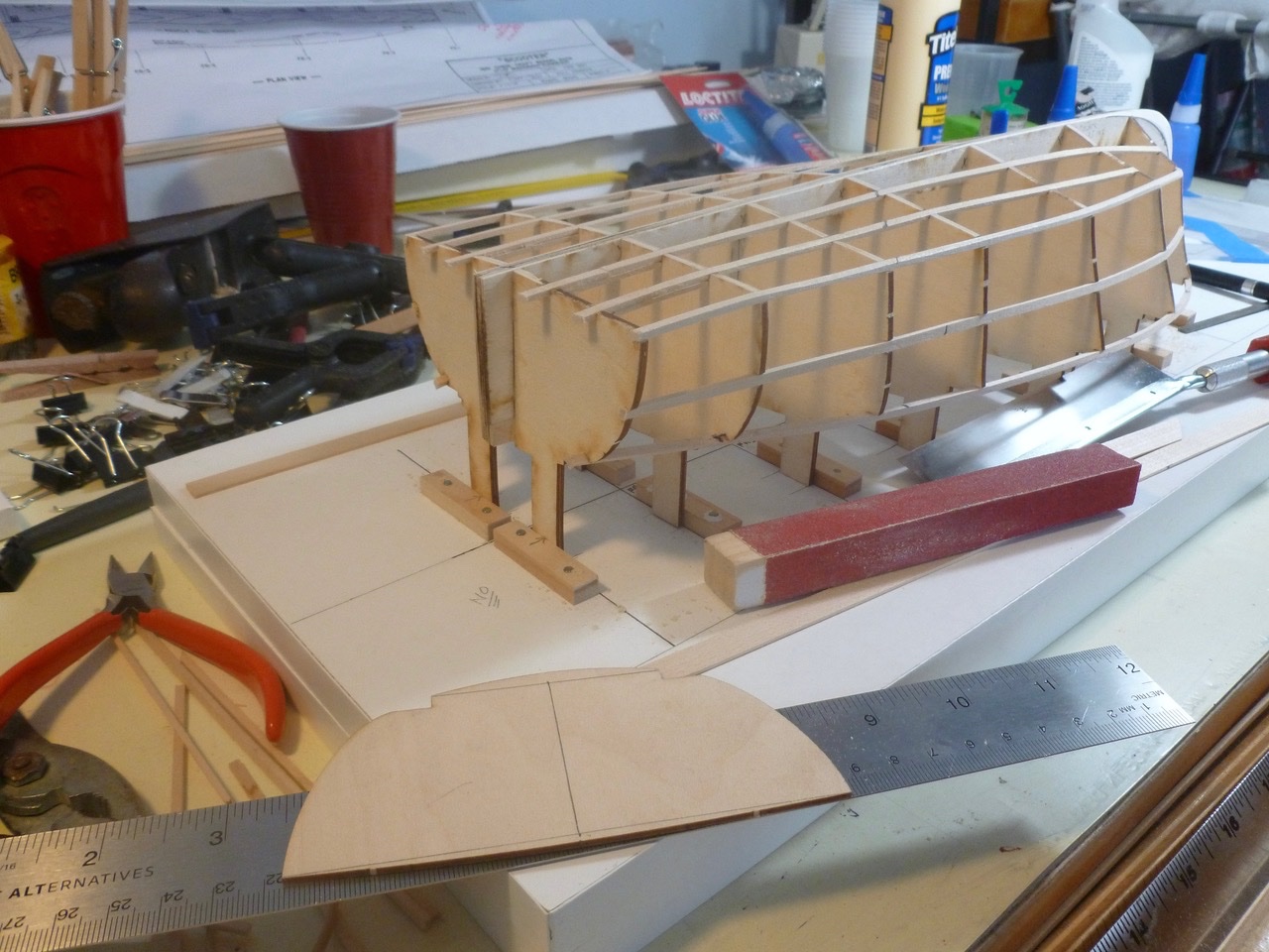
To those who dropped in or gave likes, thank you for your interest. After the initial sanding, the completed inner hull and side planking yielded a reasonably symmetrical shape. I learned that even having a building board and try square is no guarantee that all bulkheads will be perfectly aligned. The bulkhead tabs, being glued and clamped to the building board blocks after aligning with the square, kept the center in perfect register; but there was still opportunity for the port wing of one bulkhead to sneak a few millimeters out of a perfect spacing, relative to the starboard wing and adjacent bulkheads. I didn’t realize it until the inner planking was finished. Small though the error was I had to chase it throughout the build. The port quarter view below gives a preview of the challenges to make the barrel back, starting with rolling the plank across its width. The steam iron (on the no-steam setting) was used in-situ to help form the roll. Thanks for viewing. Steve
- 40 replies
-
- 9
-
-
- BlueJacket Shipcrafters
- Chris-Craft
- (and 2 more)
-
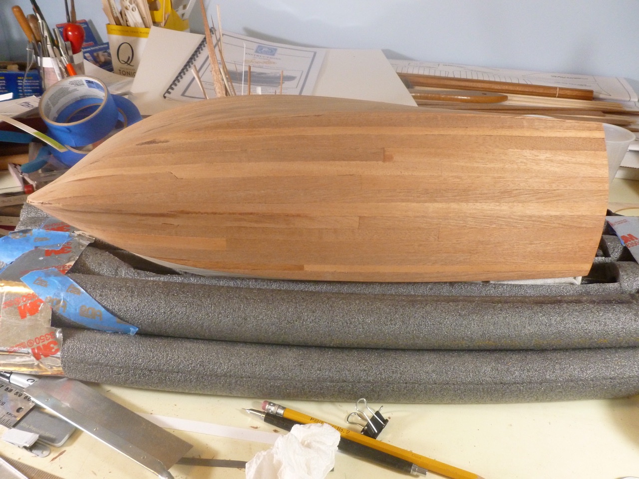
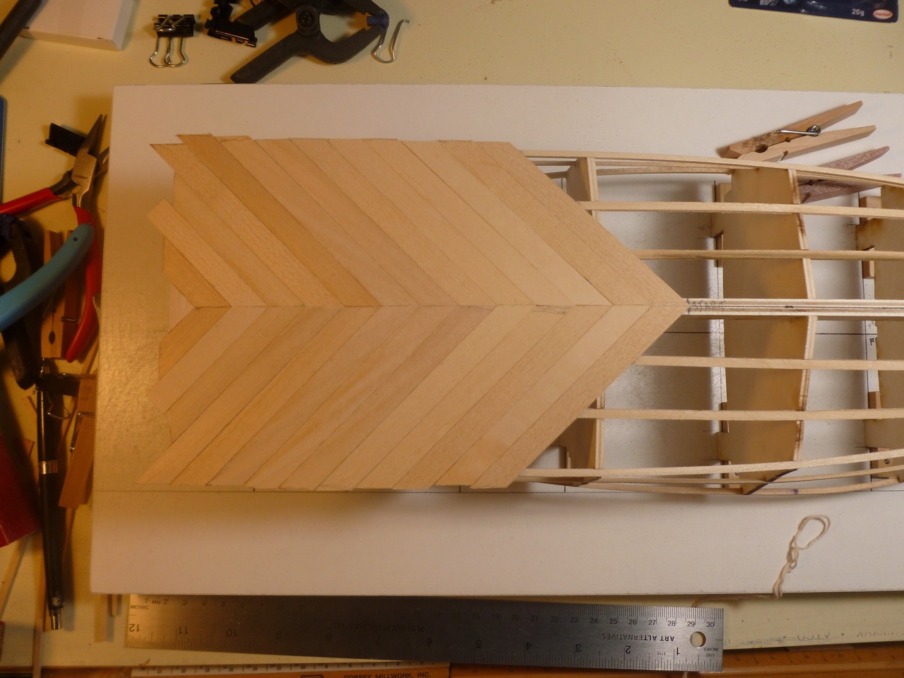
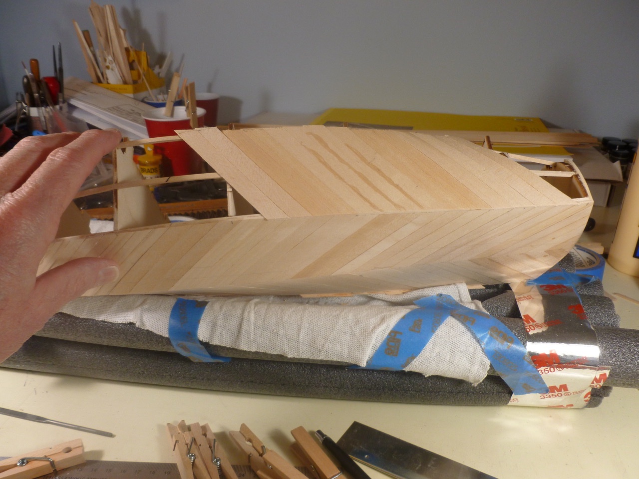
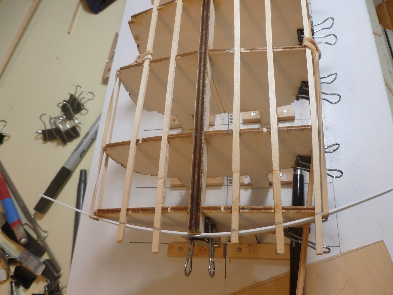
To those who dropped in or gave likes, thank you for your interest. Nic (Mr. Bluejacket), thanks for your kind words and encouragement. To Admin, thanks for correcting the title. Inner planking starts with diagonal basswood on the hull bottom. Mistakes here would be reflected in the covering layer. Fortunately the curved inner transom was a tight fit to the bottom planks. Toward the bow the bottom planks become more twisted. Bring out the iron. Fiddling was needed at the keel line to ensure a good fit between planks in every direction. The stem required a progressive bevel and flattening of the stem face to accommodate the planks and to fit it to the false stem. Inner side planking followed, starting at the middle and working to the ends; lapped over the bottom planks, curved to shape the transom barrel back, and blended to meet the bottom planks at the bow. Fortunately the inner planking came together with nothing more than a good (good equals extensive) sanding needed to make a smooth base for the mahogany planks. Thanks for viewing. Steve
- 40 replies
-
- 8
-
-
- BlueJacket Shipcrafters
- Chris-Craft
- (and 2 more)
-
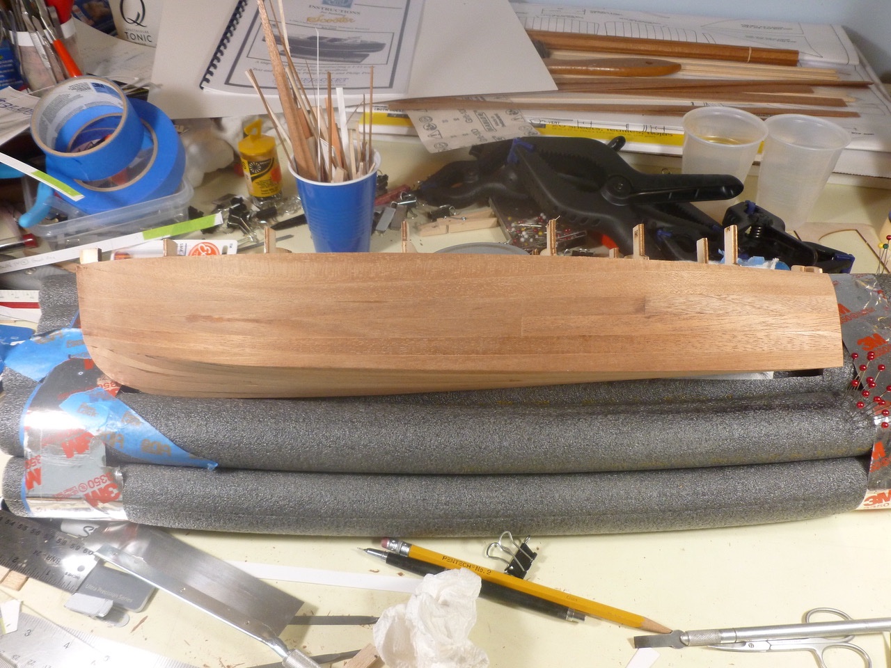
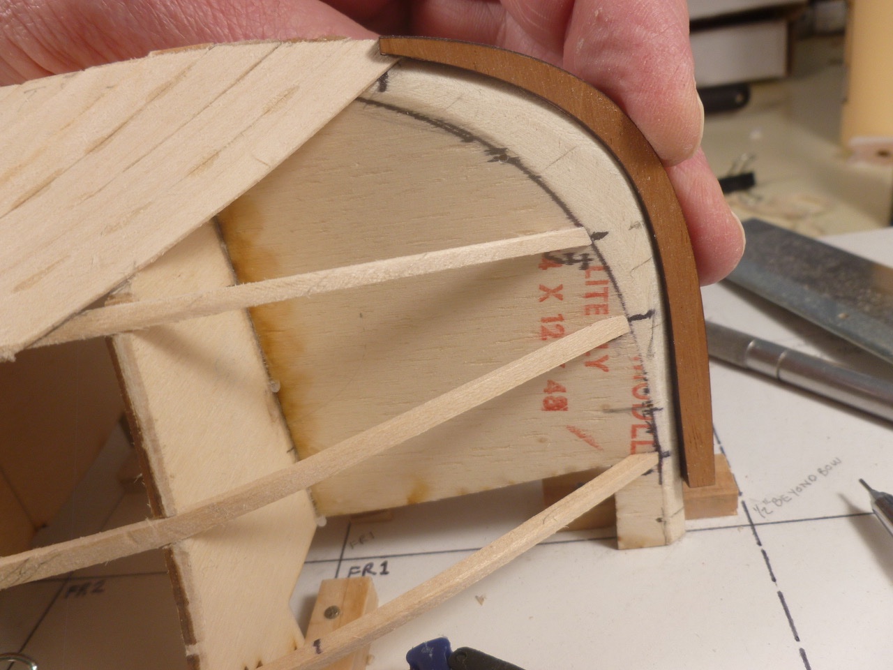
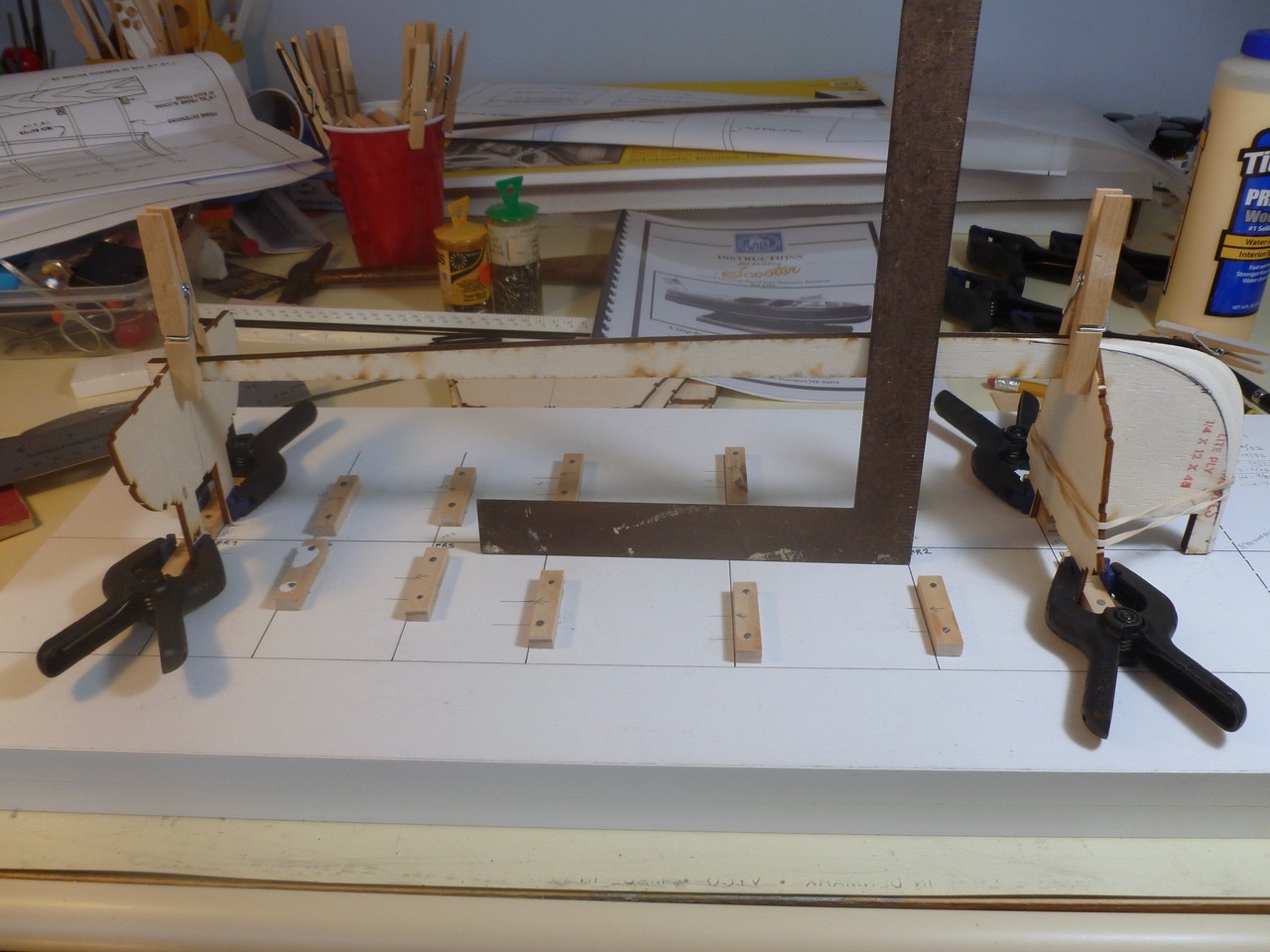
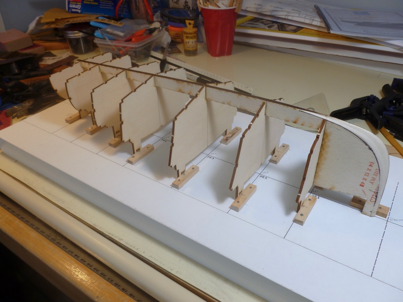
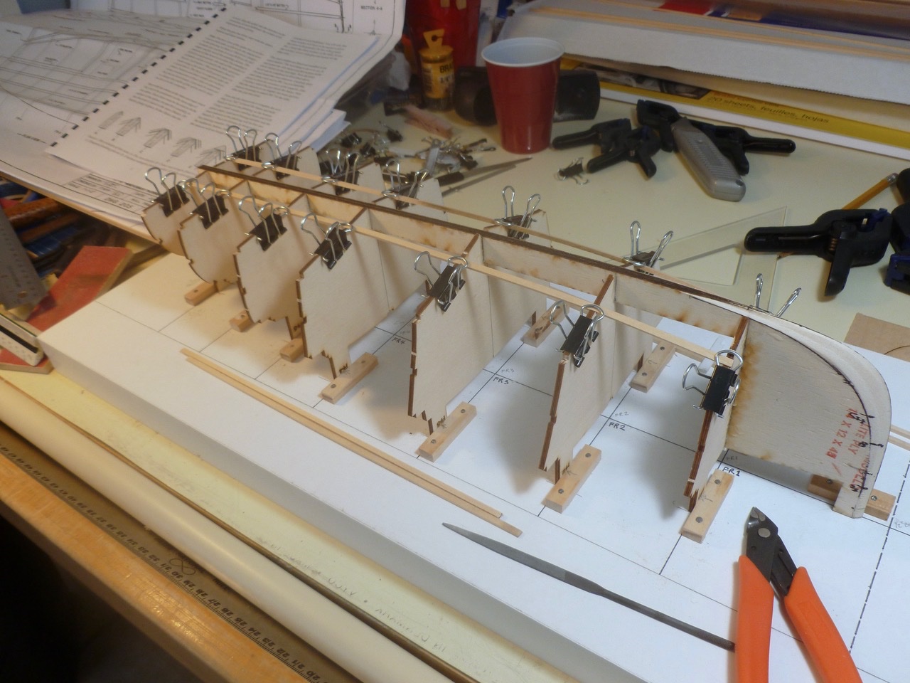
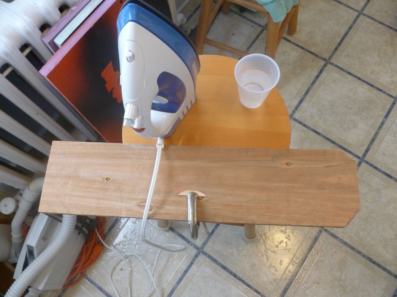
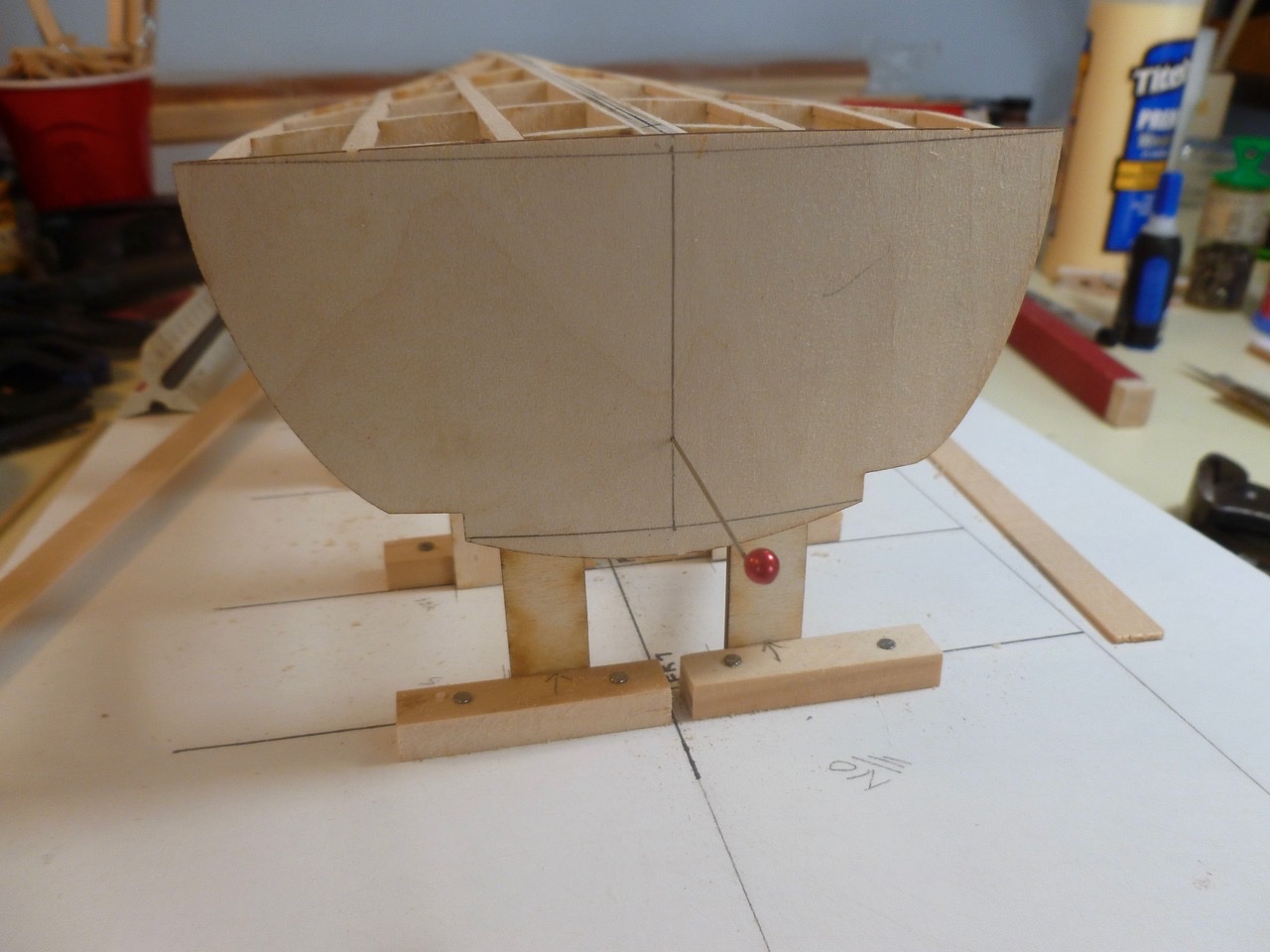
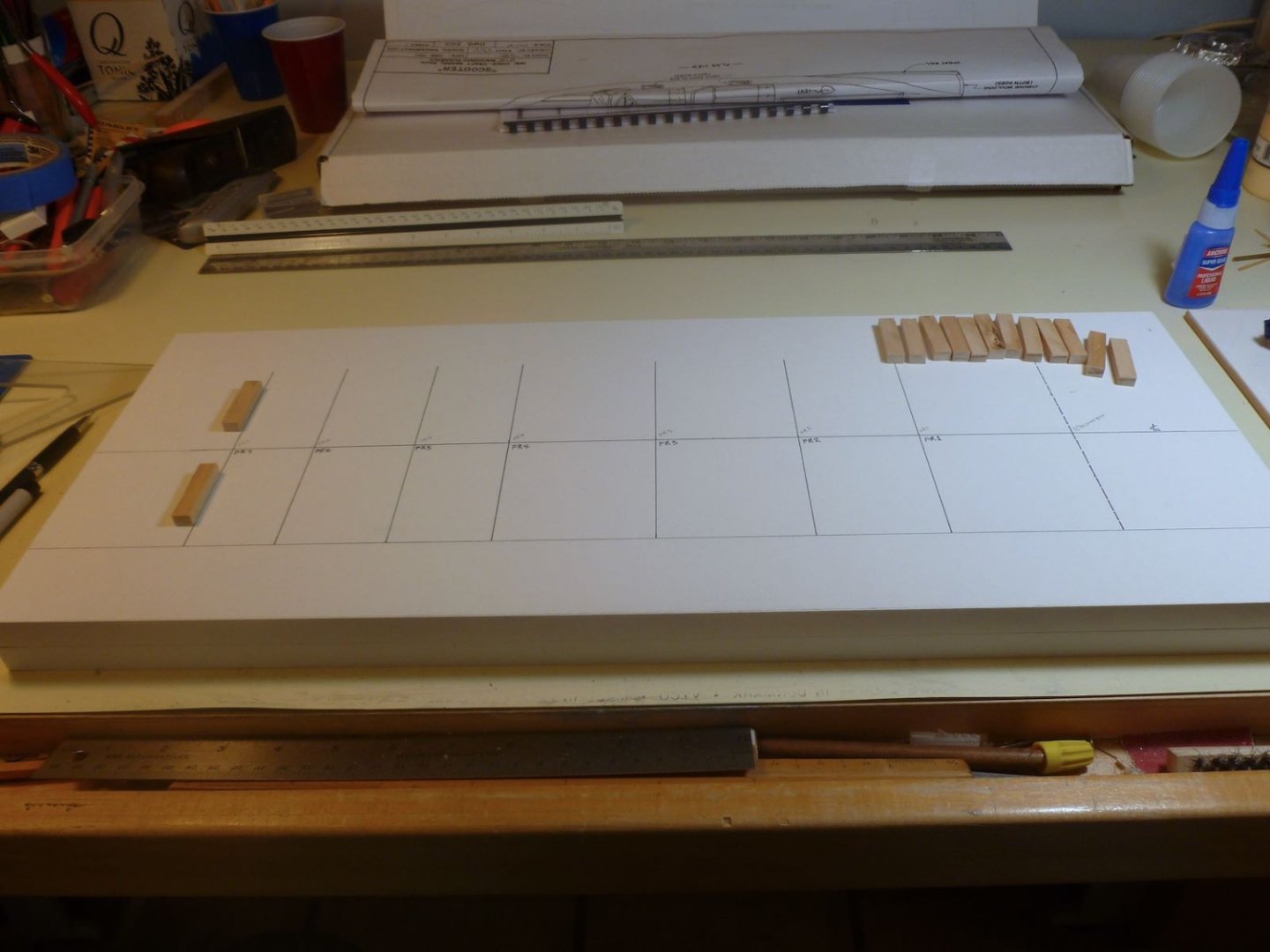
Bulkhead construction is underway. I thought I had unnecessarily complicated the baseboard by using two blocks at each frame location but the gap allowed freedom of movement for the ancient framing square. Bulkheads are set. Battens, chines and sheer are installed and left long for trimming to the inner transom. The inner transom needs a gentle curve. An old piece of styrene from the Vance build had just the right flexibility to provide a line for tail marking and cutting. A nod and thanks go to Chuck and his fine tip for easy peasy bending. My crude version of a steam station works quite well for bending and twisting. After a finger stroke of water I place the iron on the plank and gradually pull the plank out from under it, bending and/or twisting as I go. Works for strips and flat pieces like the inner transom too. As Chuck said it is really fast and repeatable to get just the right curvature. The inner transom needs to be square to the keel spline which is a bit awkward since the spline is behind the transom. A pin through a pinhole in the transom and a corresponding hole centered in the spline helped in alignment. Of course, the hole in the spline had to be drilled three times before it did what it was supposed to do. Thanks for viewing. Steve
- 40 replies
-
- 9
-
-
- BlueJacket Shipcrafters
- Chris-Craft
- (and 2 more)
-
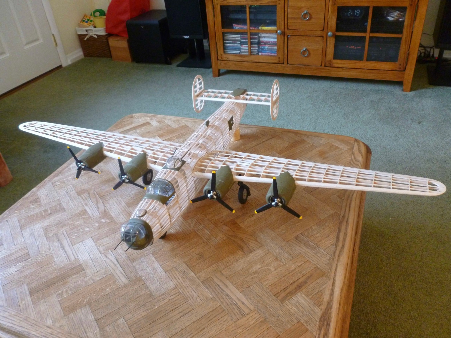
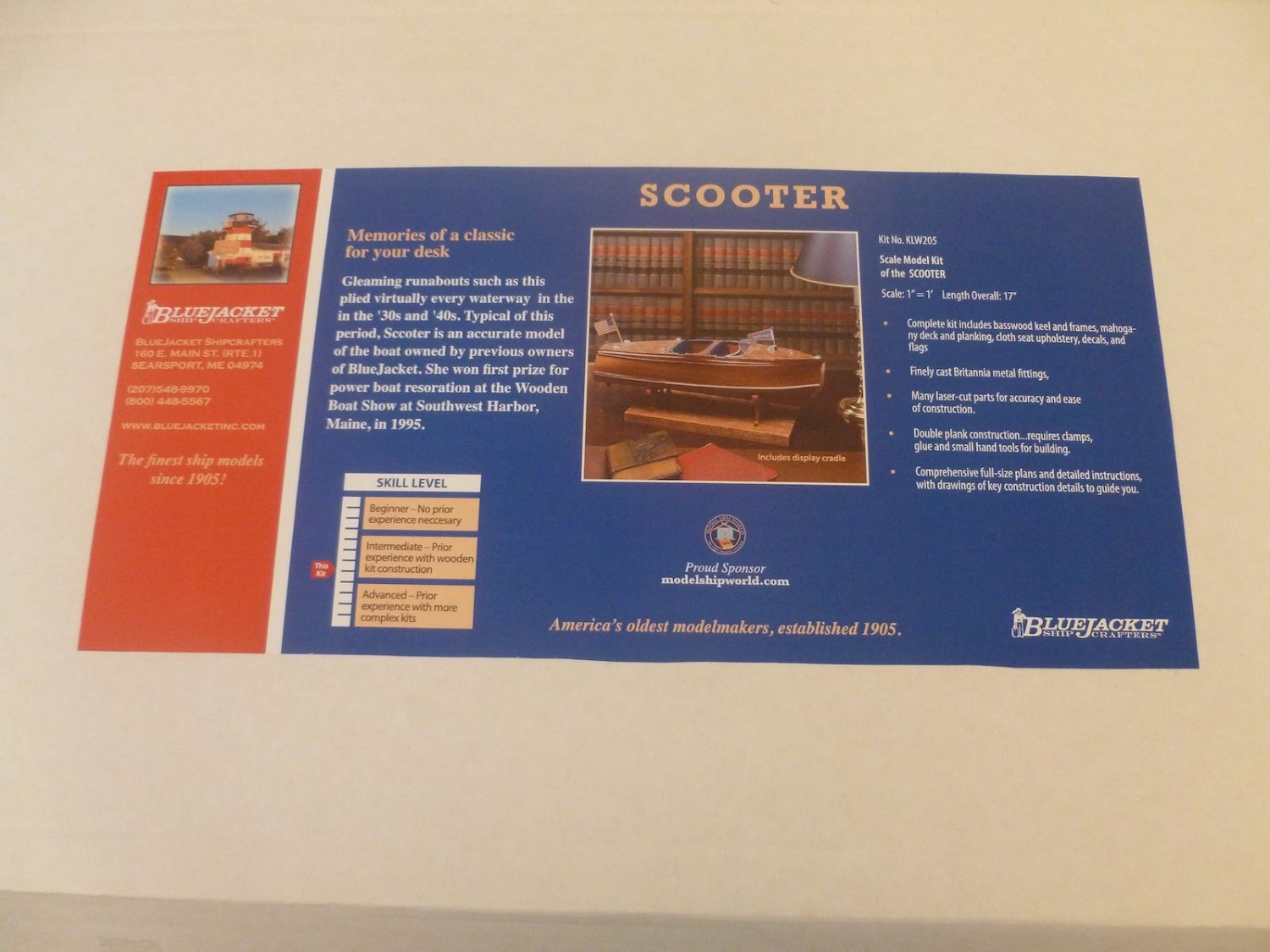
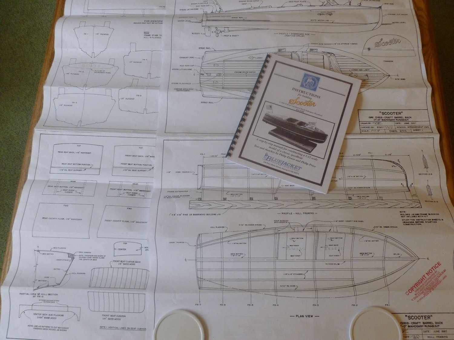
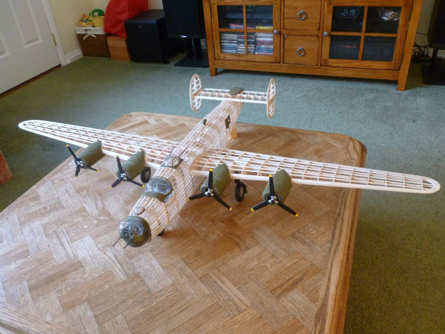
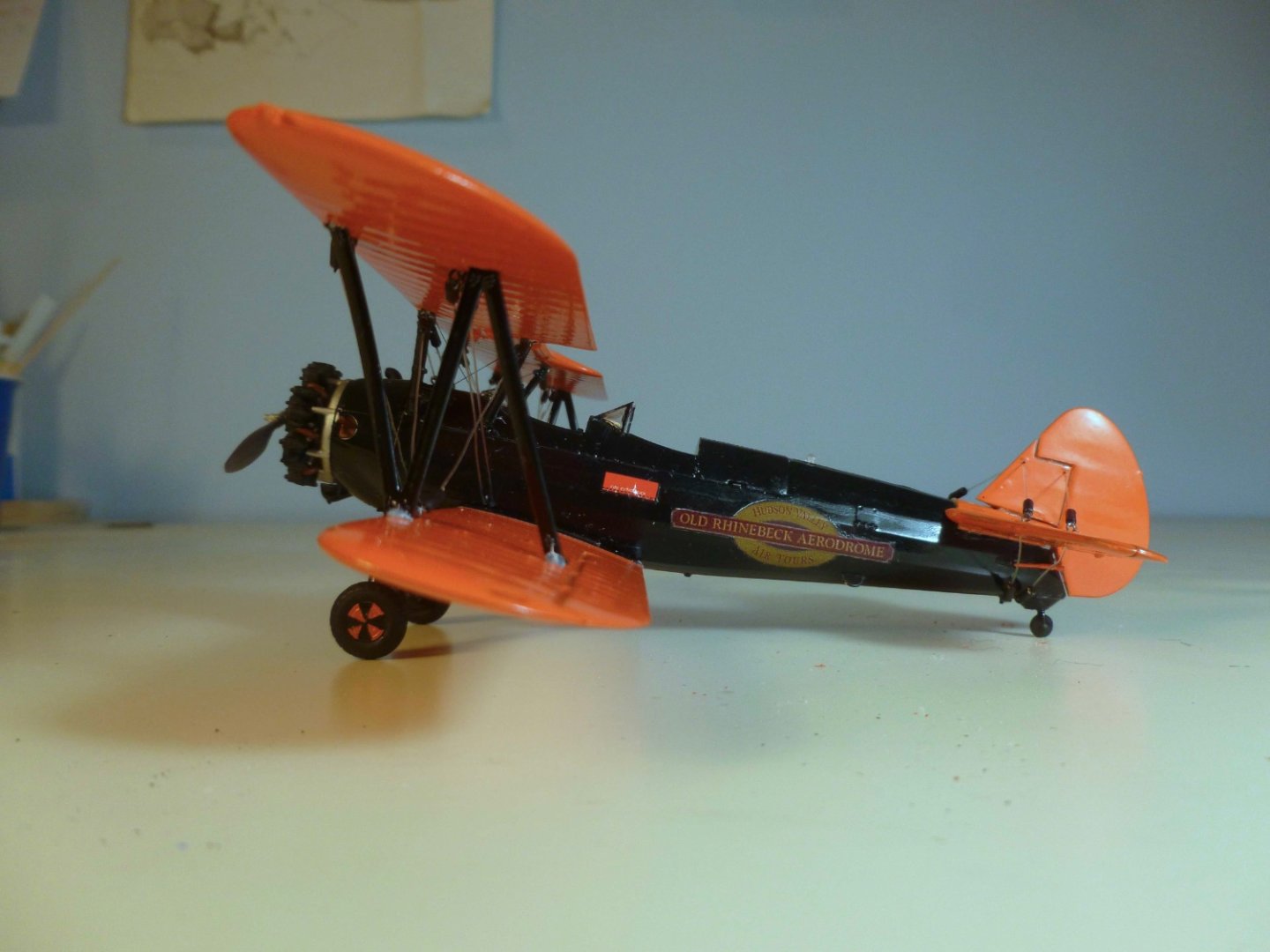
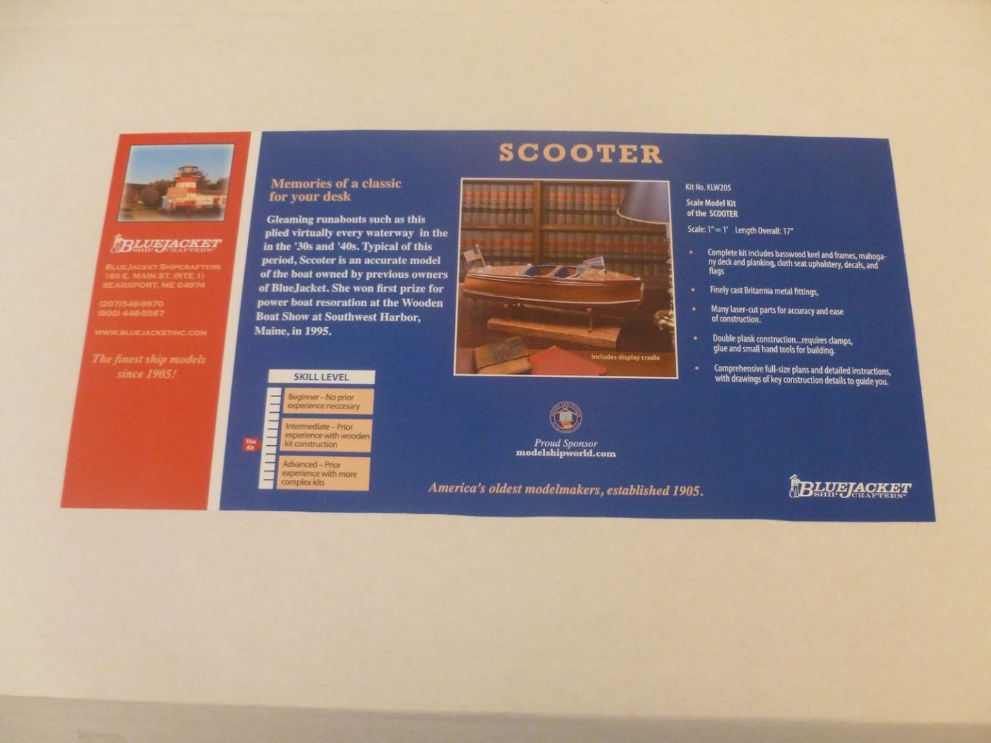
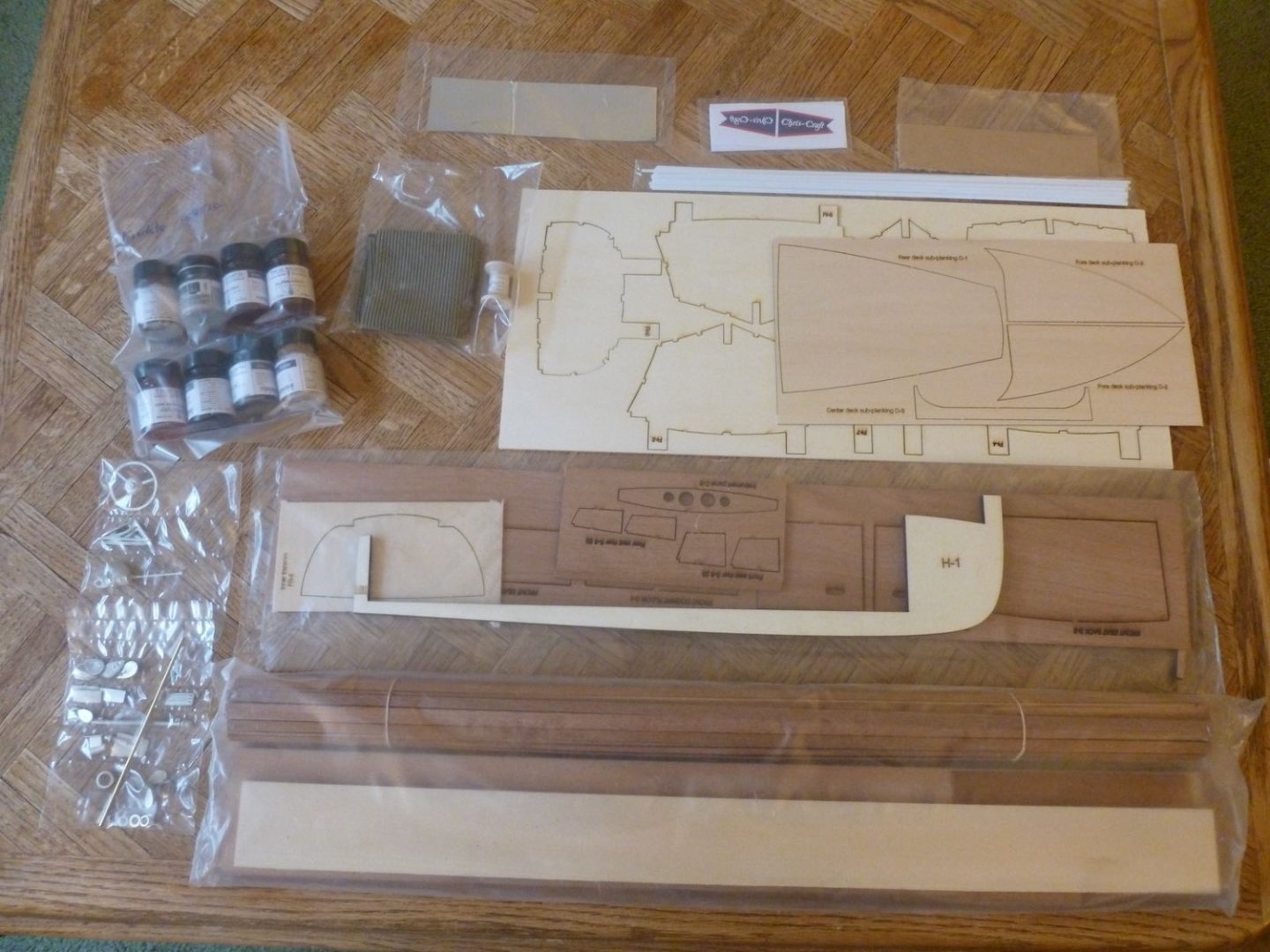
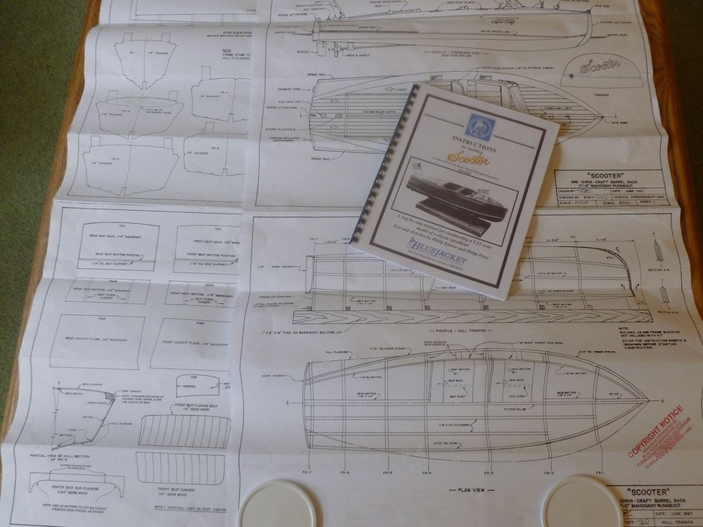
This is a build log for the 1941 Chris Craft 17 foot mahogany runabout (aka the barrel-back) kit by Bluejacket Shipcrafters. Those who have followed my previous builds may be asking “what have you been doing?” Well, apart from Covid work from home (with requisite toilet paper search), which involved babysitting a computer screen all day; and an attempt to build the Bluejacket Skiff with my grandson, which has taken a back seat to swimming, golf lessons, school activities and playing with friends, I completed a few non-nautical projects. First up was a large (4 foot wingspan) balsa model of the B-24 Liberator from a kit sent to me by my brother. He said my late father told him the Liberator flew out of the English base where my father was stationed during WWII. A first attempt that shows good effort if you don’t look close, although I was happy with the canopy masking. Next was a small plastic biplane, built to commemorate a hair (and stomach) raising flight my grandson and I took at the Old Rhinebeck Aerodrome, located near the historic village of Rhinebeck, New York. The results below are another first attempt, not only at a small plane but also of a handmade waterslide decal. The last was a labor of love. There’s a lot of family history behind it but suffice it to say that over 35 years ago I made a three foot tall teddy bear (from a Brooke Shields Moon Bears pattern) for my son, and a doll for my daughter with nightie and slippers in honor of my late mother, who loved sewing, children and things that endure, not necessarily in that order. More recently I followed that up with three more bears for family members young and not so young. Daughter in law suggested vests which added a certain panache. Now that we’re up to date let’s get back to the water. When I was a young lad my parents took my sister and me to Lake George in upstate New York. My primary obsession was Fort William Henry at the southern end of the lake, but conveniently there was a boat ride service operating across the street from the fort. The conveyances were drop-dead gorgeous mahogany boats, both double and triple cockpit. I still remember the intoxicating burble of the engine exhaust and feeling of limitless power as I experienced my first powerboat ride. My fading memory is sitting in a triple cockpit, but considering I have zero experience with bright finish mahogany models I thought the smaller double cockpit barrel-back would more likely yield a successful result (Clint Eastwood as Dirty Harry: “A man’s got to know his limitations”). My goal was to build it with no filler, tight joints, upholstery (there’s that fabric link again) and a shiny finish. The kit arrived in a timely manner and included the usual assortment of strip and sheet goods, laser cuts, well done drawings and an instruction manual. Initial setup requires a flat and stiff build board. Two pre-made closet shelves from the local DIY store that I glued together for stiffness were a bit belt-and-braces but met the specs nicely. After serving their purpose they’ll be good for a heavy load of stored junk if I build a very narrow closet. Thanks for viewing. Steve

- 40 replies
-
- 9
-
-
- BlueJacket Shipcrafters
- Chris-Craft
- (and 2 more)
-
Thanks for sharing a challenging build. Lots of valuable lessons (and great results) for those of us going down the same path. I purchased the Scooter kit a few days ago, just before seeing your build log. I thought all the mahogany fitting and shaping would be daunting but it looks like you have met it head on. I wish you good sailing to a successful finish. Steve
-
Nils, Thank you for sharing your workshop. I wish you and your family a happy holiday season. Steve
-
Nils, Your work is an ongoing feast for the eyes, made even more wonderful by your creativity with what appears to be all hand labor with a minimal set of tools. You've probably done it before but would you mind sharing what, if any power tools you use and what are your favorite hand tools? Thank you Steve
-
Denis, Best wishes on a successful build. Here's some little side stories. My father in law flew in B-17s and was shot down over Germany, ending up in a prison camp. One morning they woke up and discovered their captors had abandoned the camp and left the gate open. They debated whether to leave but decided to stay until friendly troops arrived, figuring they would be safer there than running around in the woods with a war going on. My dad served on a bomber base outside London and one of his choice duties was to bring new flying crews into London to see the sights. During one visit he met my mom in Covent Garden which had been turned into a dance hall for GIs. Build it proud for them and for all those who served. I'm sure you will do it justice. Steve
-
Carl, Please let your friend know we are praying for them. Remember to take a break from life now and then for some shipbuilding therapy. Steve
-
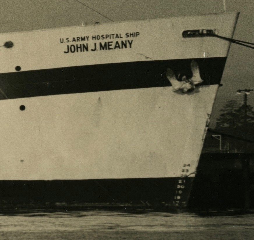
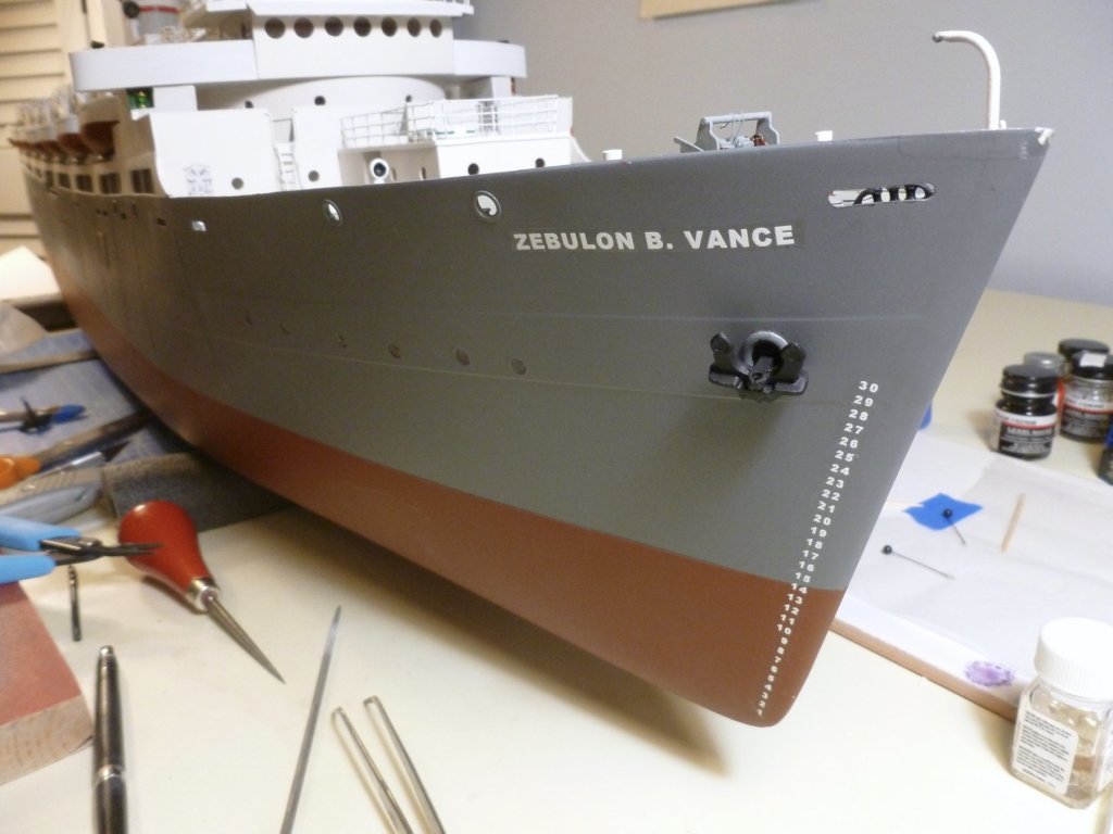
Lou, the waterline location came from the kit instructions. The distance between numbers on the model is approximately 1/8" (1 scale foot) resulting from experimenting with row spacing in the word processing software. Those two together gave me 14 scale feet from near the hull bottom to the waterline. When I was drawing the waterline it didn't occur to me to look at photo 1 - I was more focused on the discrepancy between the waterline location shown in the model instructions and the model side view on the full size drawing. As to why the Meany shows the boot at 22 feet while the Vance was painted at 10 feet, who knows? Maybe when they added the superstructure, the air conditioning, all the hospital rooms and equipment the ship sat lower in the water. It didn't seem to make sense to have a strip of depth markings that are very close to a scale 30 feet high and then put the one foot mark someplace other than near the bottom of the ship, and since the model sailed well sitting at the painted waterline I let the 14 foot marker lay where it fell. One justification is that the Vance in war bride mode was closer to the Meany configuration than to the Vance as a liberty ship so being off two feet (14 vs 16 ft) where the ship sets in the water seems a reasonable compromise, even if the Meany and war bride Vance boot tops don't line up. Now there's some confusion and arbitrariness! Thanks for caring. I hope you are feeling better. I'm going in for the first of two carpal tunnel hand surgeries next month to try to keep these old parts working. Steve
- 446 replies
-
- 2
-
-
- zebulon b vance
- deans marine
- (and 3 more)
-
Denis, So much great detail in such a small space - very impressive. The pictures are very sharp without the lens smudge. Thanks for sharing and making the build entertaining. Steve
-
Andrew, It's coming along very nicely. The extra detail in the binnacle looks sharp. Steve
-
To those who gave likes, thank you and thanks for stopping by. Carl, I was actually looking at the Vance in her John J. Meany hospital mode (see below) when I was trying to figure out how to align the numbers to the hull. Looking at it now I see the numbers are horizontal but the alignment is on an angle. That would be an interesting experiment in a word processor. In any event I ended up with neither fish nor fowl since the strip of numbers isn't vertical nor does it perfectly align with the bow 🙄. At least the name is pretty straight. Maybe I'll have better luck next time. The print shop said they had to go to one of their other locations because it was the only one with a printer that used white ink on waterslide decal paper. I read about such printers but didn't know they are still around. Maybe they would ship overseas. Steve

- 446 replies
-
- 4
-
-
- zebulon b vance
- deans marine
- (and 3 more)
-
To those who gave likes, thank you and thanks for stopping by. Denis, thanks for your kind comments. I'm guessing the printer can make anything you send them into a waterslide decal. I made the name and numbers in MS Word and saved the file as a pdf, then emailed that to the printer. I used black for the text so I could see it and asked them to change the color to white. Roman numerals are just a bunch of letters (I - V - X - M - C) so that should be easy. For the numbers I set the alignment to Right Justified so they would line up along the right edge and experimented with row spacing until I got something that was close to a scale one foot between numbers. I also included two different size names so I could have a choice. It was all on one sheet of paper. Steve
- 446 replies
-
- 2
-
-
- zebulon b vance
- deans marine
- (and 3 more)
-
Thanks Jack. The nice thing is the numbers are on a single strip, as is the full Vance name. Trim, wet, slide, done. I did the layout in MS Word and experimented with the row spacing for the numbers so they are about a scale foot apart. Steve
- 446 replies
-
- 4
-
-
- zebulon b vance
- deans marine
- (and 3 more)
-
To those who gave likes, thank you and thanks for stopping by. Lou, we’re so used to driving around the pond on the way home that we usually just give it a quick look, but had I known it would be so easy to sail on it I probably would have done it a lot sooner. Steve A tasty alphabet soup What a find! After searching all over the web I discovered that a local printing company, who I dealt with years ago for architectural drawing printing, can make waterslide decals with white letters. They had to go to one of their out of town locations to make them but all I had to do was go around the corner to pick them up. Once I give the decals a shot of clear matte the semi-shiny background should go away. If anyone has a need the web link is www.godataflow.com. I used the Albany, NY location.
- 446 replies
-
- 7
-
-
- zebulon b vance
- deans marine
- (and 3 more)
-
To those who gave likes, thank you and thanks for stopping by. Lou, I truly appreciate your hanging in there throughout the build and for your helpful guidance. The Vance carry to the pond shore was about 20 feet. It's a beautiful spot at the end of our block. Steve
- 446 replies
-
- 2
-
-
- zebulon b vance
- deans marine
- (and 3 more)
-
To those who gave likes, thank you and thanks for stopping by. Carl, Legodude has had a very busy summer. Hopefully I can steal some time for us to work on the skiff this fall. Jack, yes we are still in the area but not as close to the Canal. Kevin, thank you for your kind remarks and for hanging in there. I'm learning a lot watching your builds. Steve
- 446 replies
-
- 4
-
-
- zebulon b vance
- deans marine
- (and 3 more)
-
Kevin, sorry for my waste of a post. Looks like soldering heat transfer techniques have already been well covered😊 But it's a great build nonetheless. Steve
-
Kevin, it's looking great. I feel for your soldering frustration as I've had the same when trying to solder tiny bits. Regarding heat transfer ruining made joints, when I was soldering plumbing pipe back in the day I would occasionally put a damp rag around the made joint while soldering something nearby. I don't know if this technique transfers to PE world but a scaled down version might be worth trying on some scrap. Thanks for sharing the build. Steve