ESF
-
Posts
381 -
Joined
-
Last visited
Content Type
Profiles
Forums
Gallery
Events
Everything posted by ESF
-
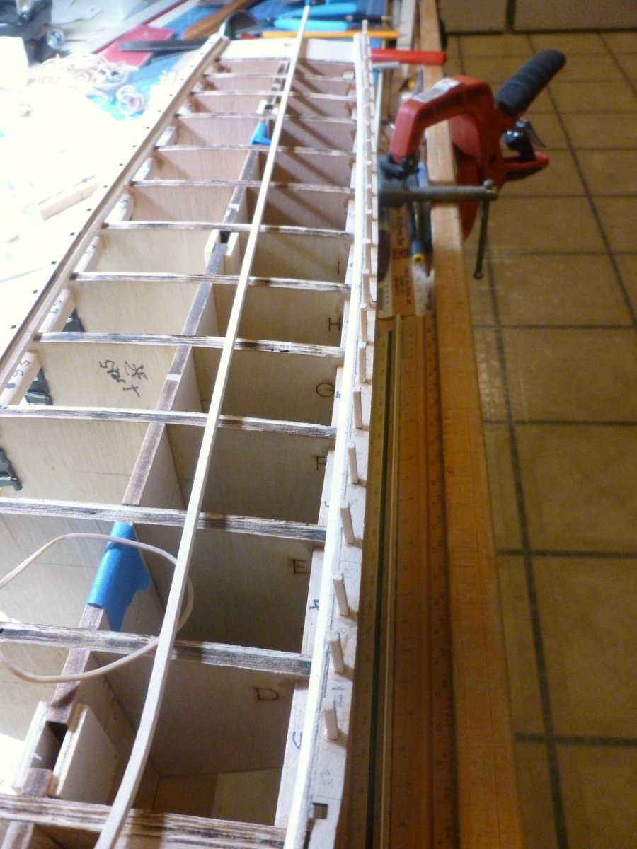
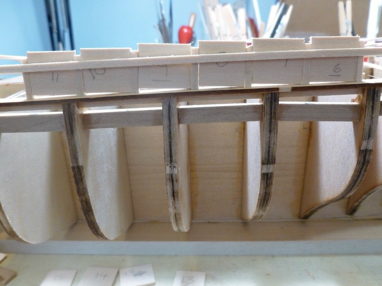
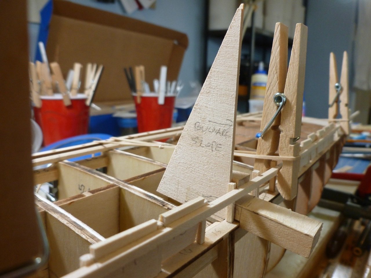
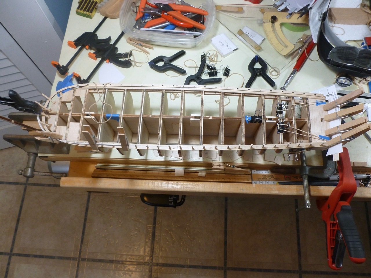
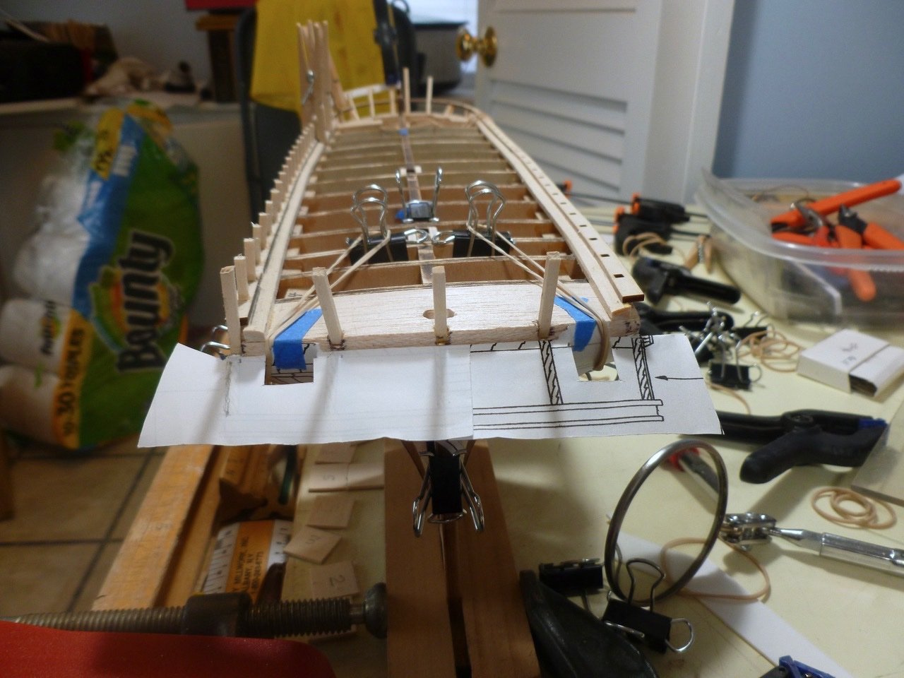
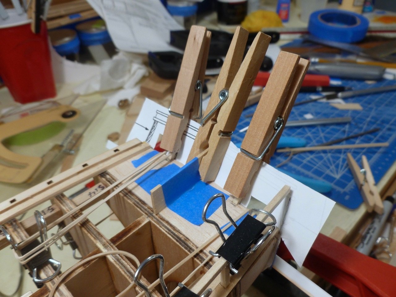
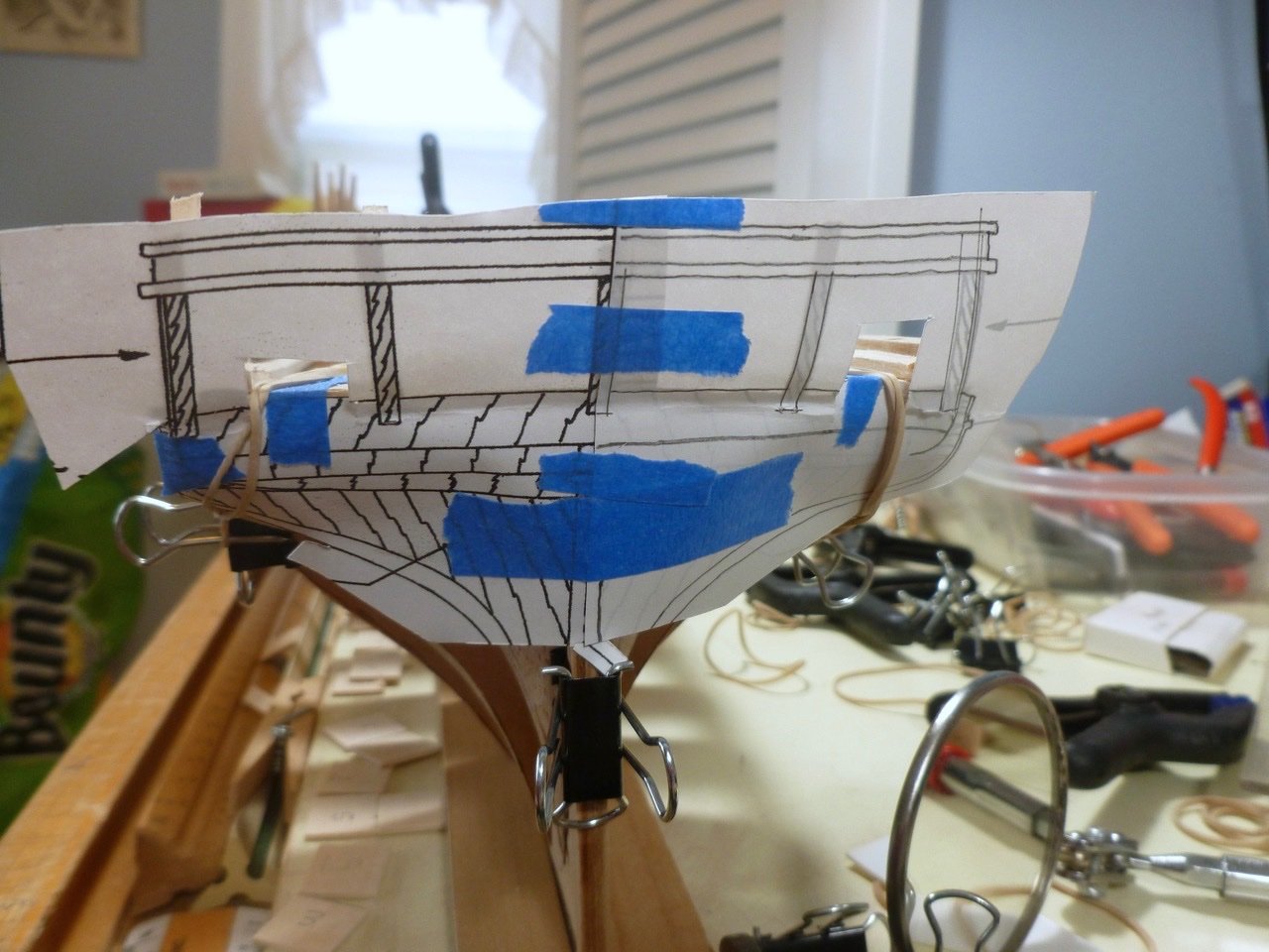
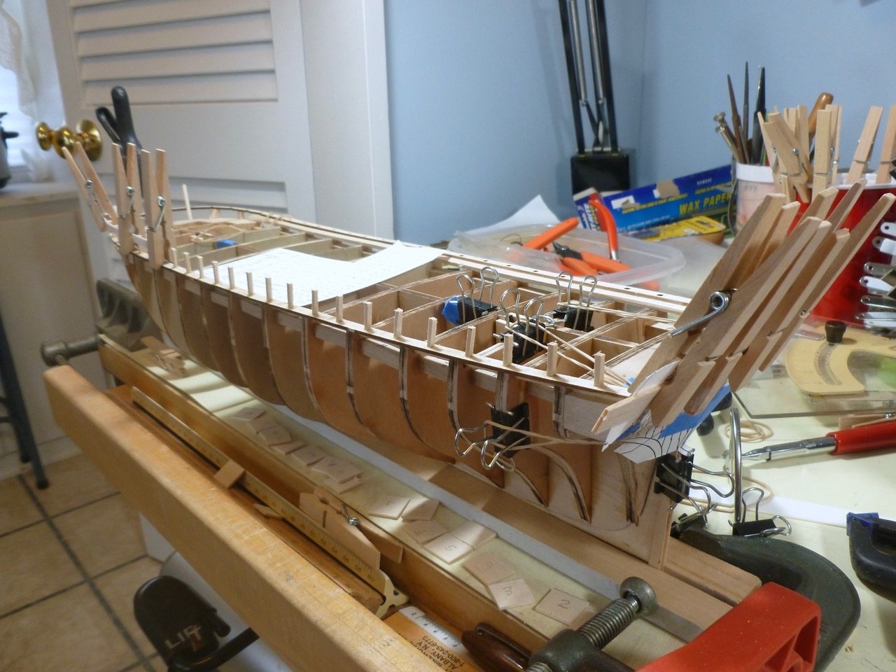
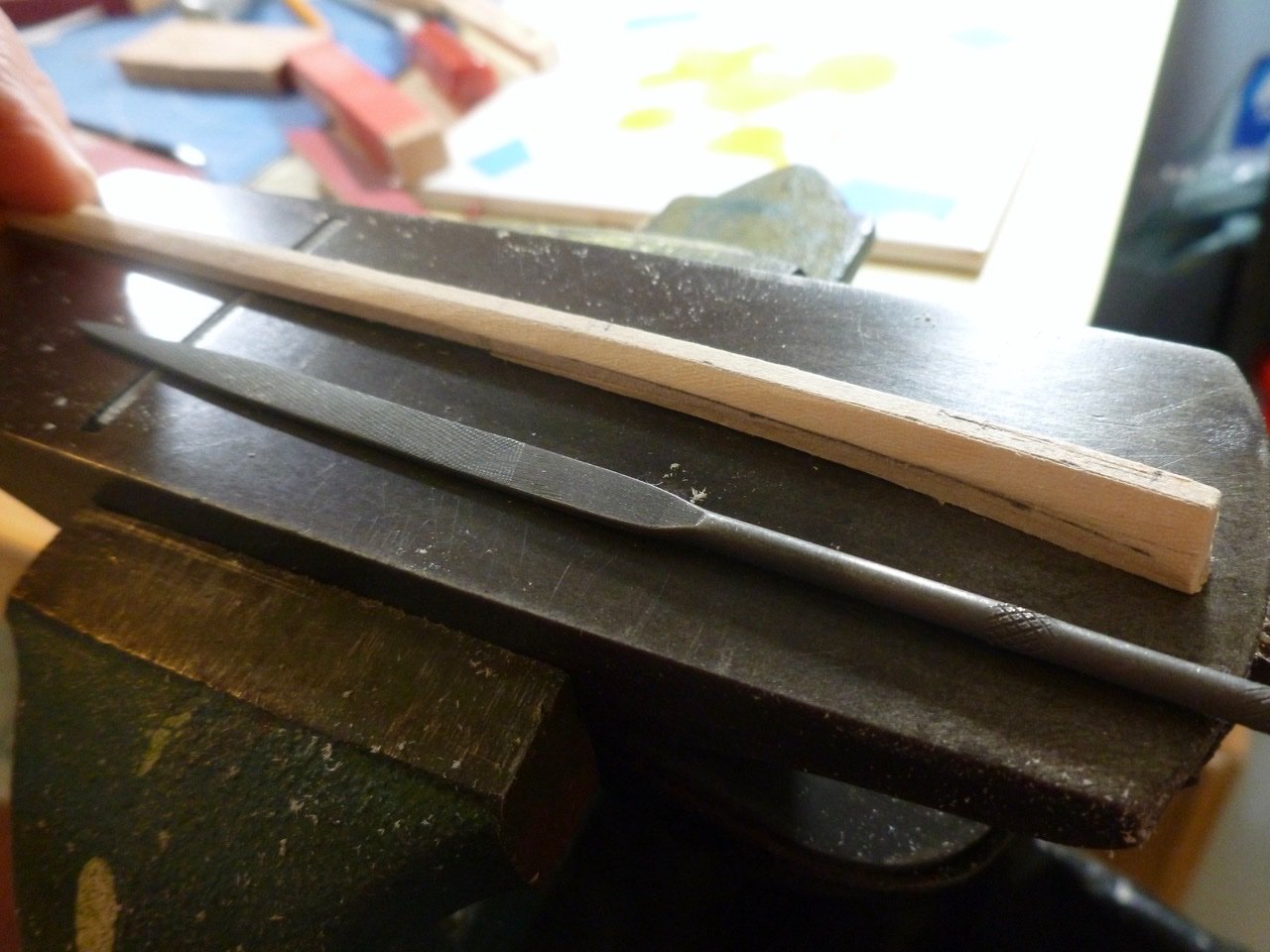
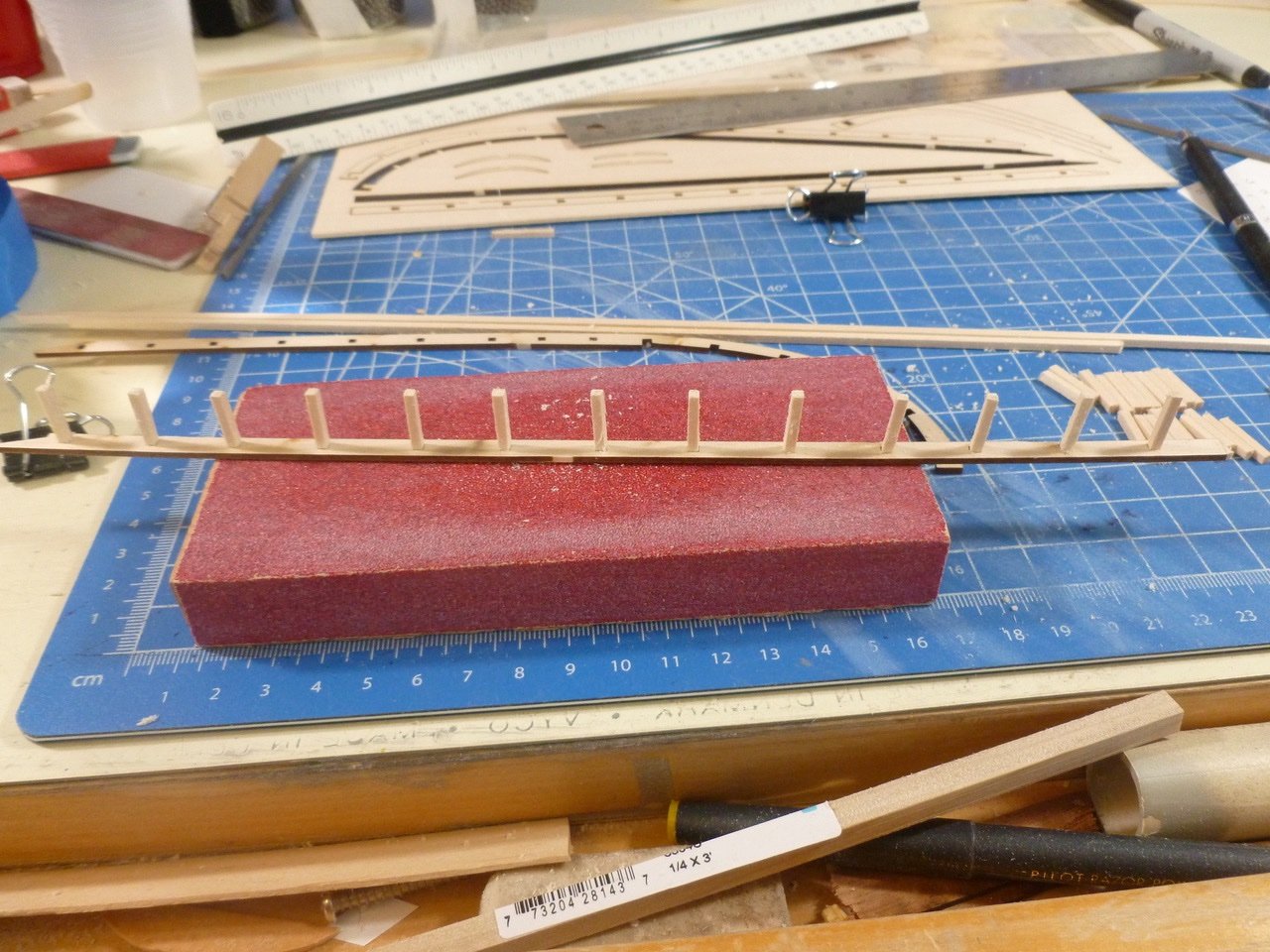
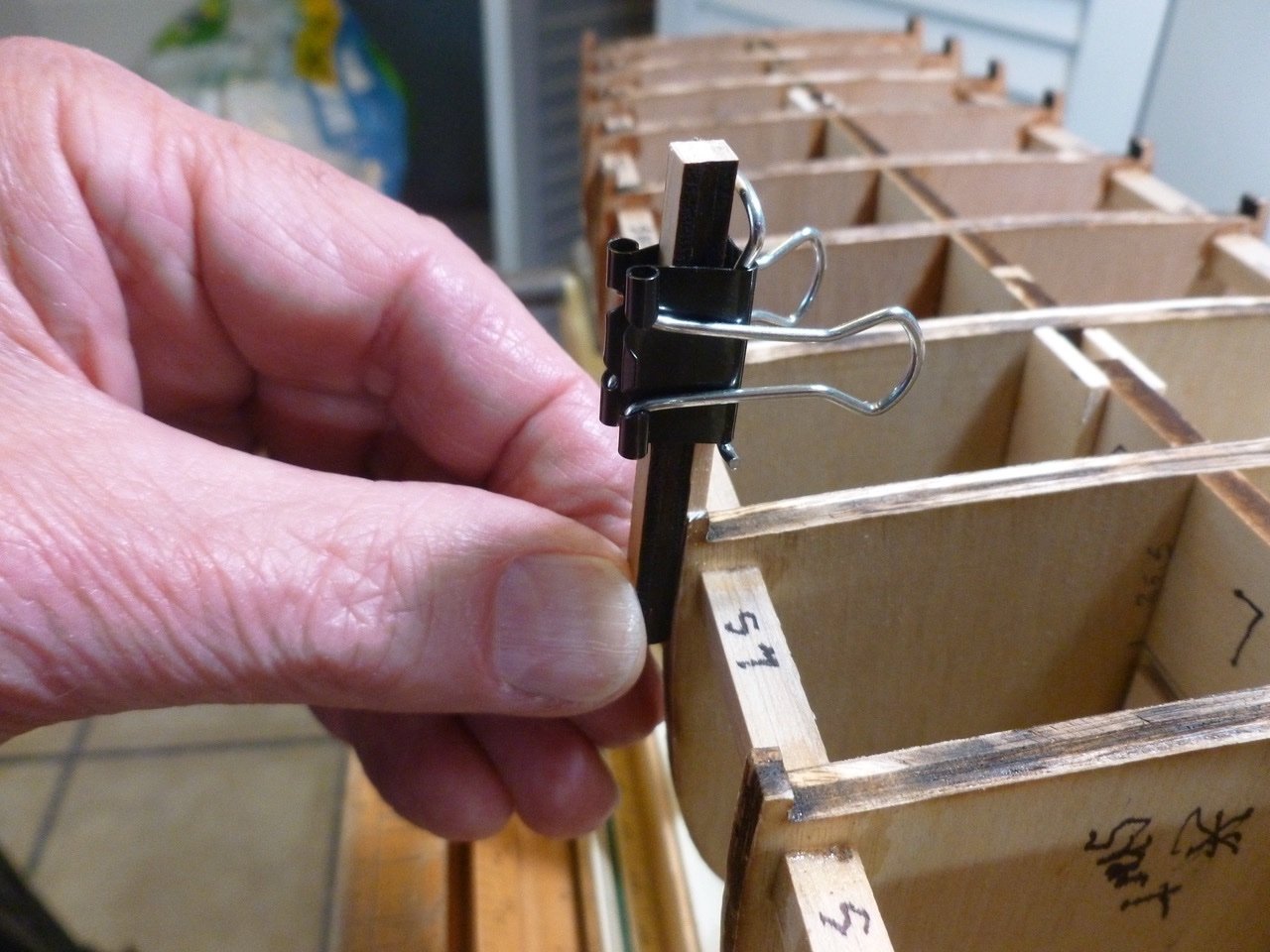
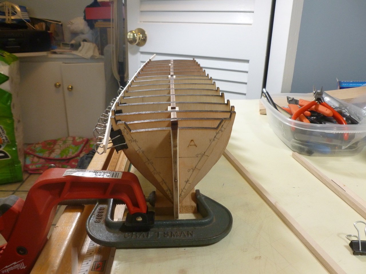
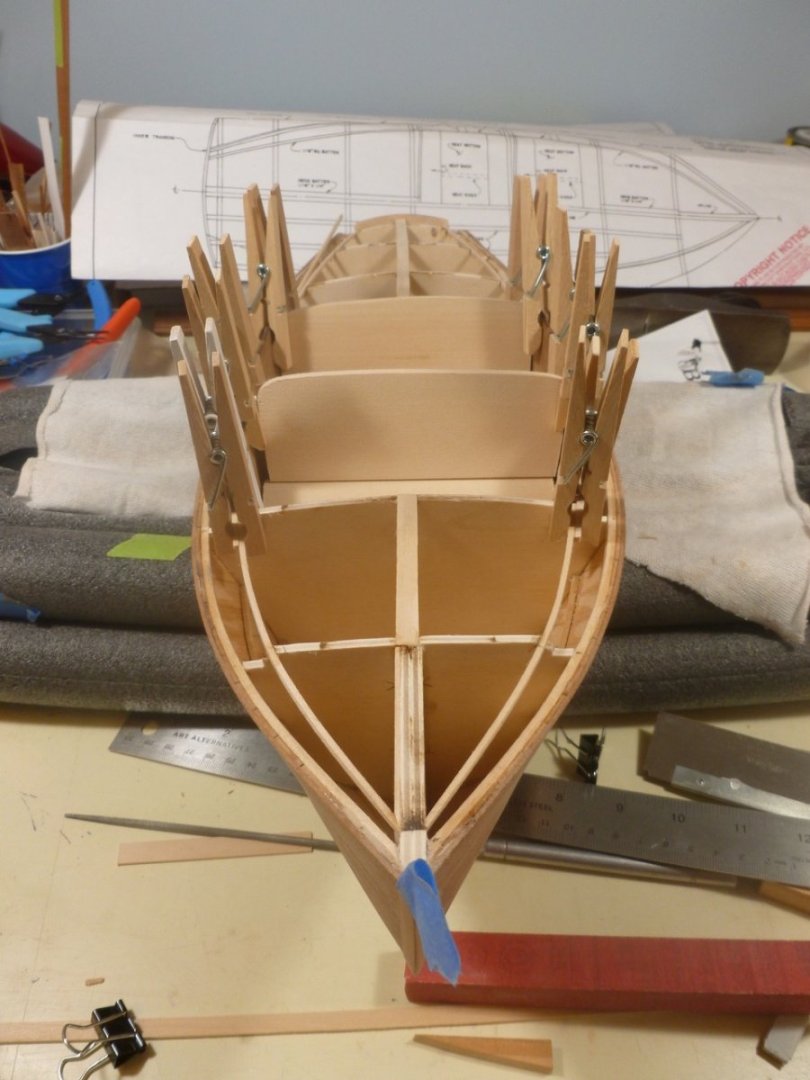
 To those who dropped in, thank you for your interest and support. The bulwark stanchion template that I thought would be wasted found a use in setting the stanchion angle. Perhaps not perfect since I had to eyeball the level but the stanchions came out in good alignment. I cut spacers to help with vertical alignment of the stanchions. Each spacer matched the width between the laser cut holes in the planksheer. I started at midship where the stanchion was square with the planksheer. Once that was glued in place it established a plumb line for vertical alignment. Using the spacers I placed the remaining stanchions but did not glue them. The angle between the bottom of the spacers and the planksheer could be ignored since the sides were parallel. Once the stanchions were placed, and before gluing, I ensured they were fully engaged and flush with the bottom of the planksheer. To avoid sitting on the floor to look up at the planksheer underside I used a little mirror on a handle I purchased years ago in my architectural practice to confirm whether doors were painted on top and bottom. I initially cut the stanchions slightly long, then marked each stanchion height using dimensions scaled from the drawings. After installing a batten along the marks I trimmed to final height with a drum sander in a Dremel. I use a clothes pin horizontally placed around each stanchion to hold it steady against the batten during sanding (after snapping the first stanchion with a heavy sanding hand). At the bow I used a strip of plastic to help set the timberhead sweep. At the stern I cut a template to set the angle using info from the drawings. For spacing and angle of stern framing I copied the stern view and taped it to the transom, after cutting two holes to allow for taping and rubber banding a batten. By folding the transom drawing I could cut the mounting points without removing the drawing. Now one side is set and hopefully the lessons learned will speed up the other. Thanks for viewing. Steve
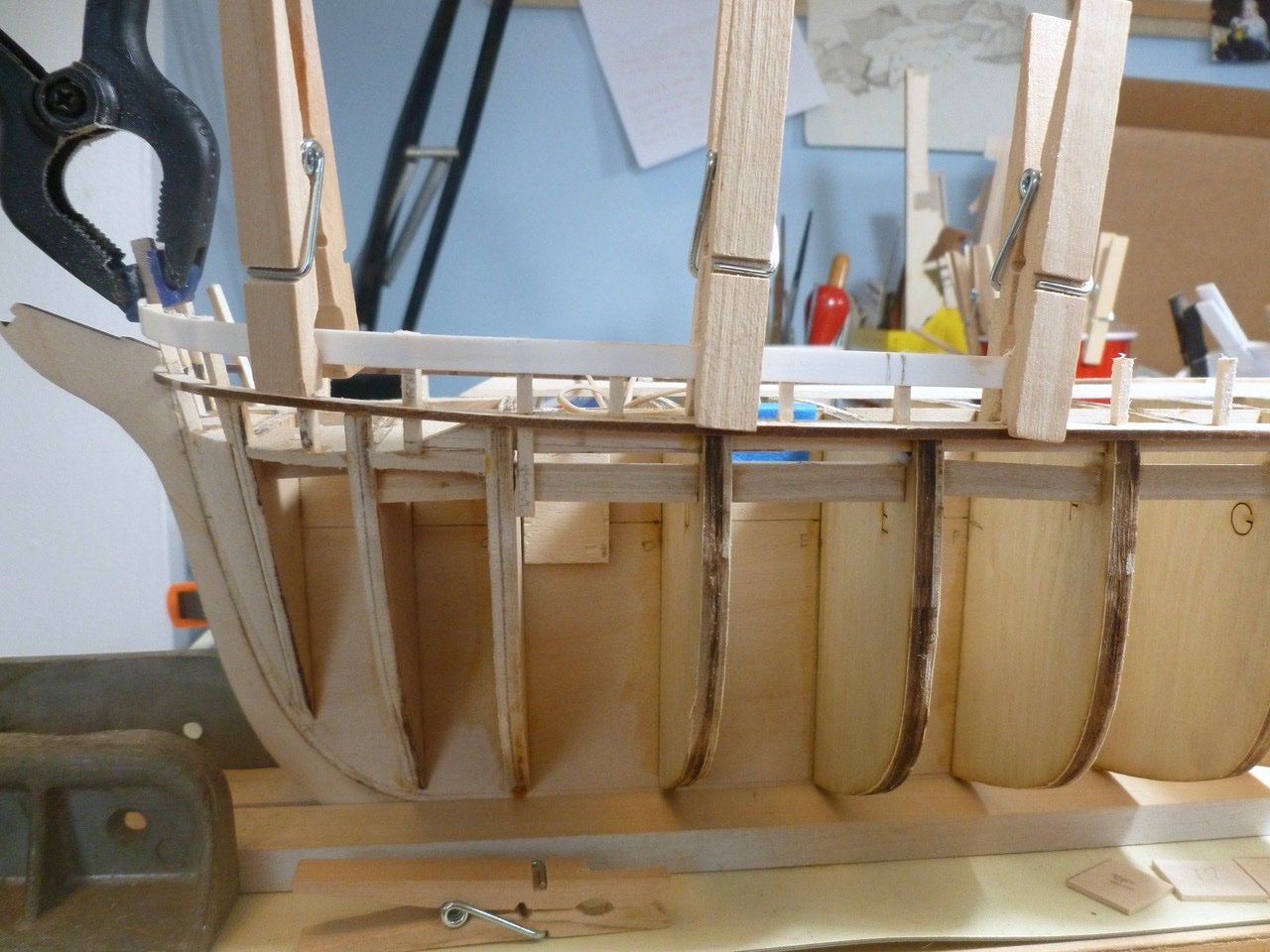

-
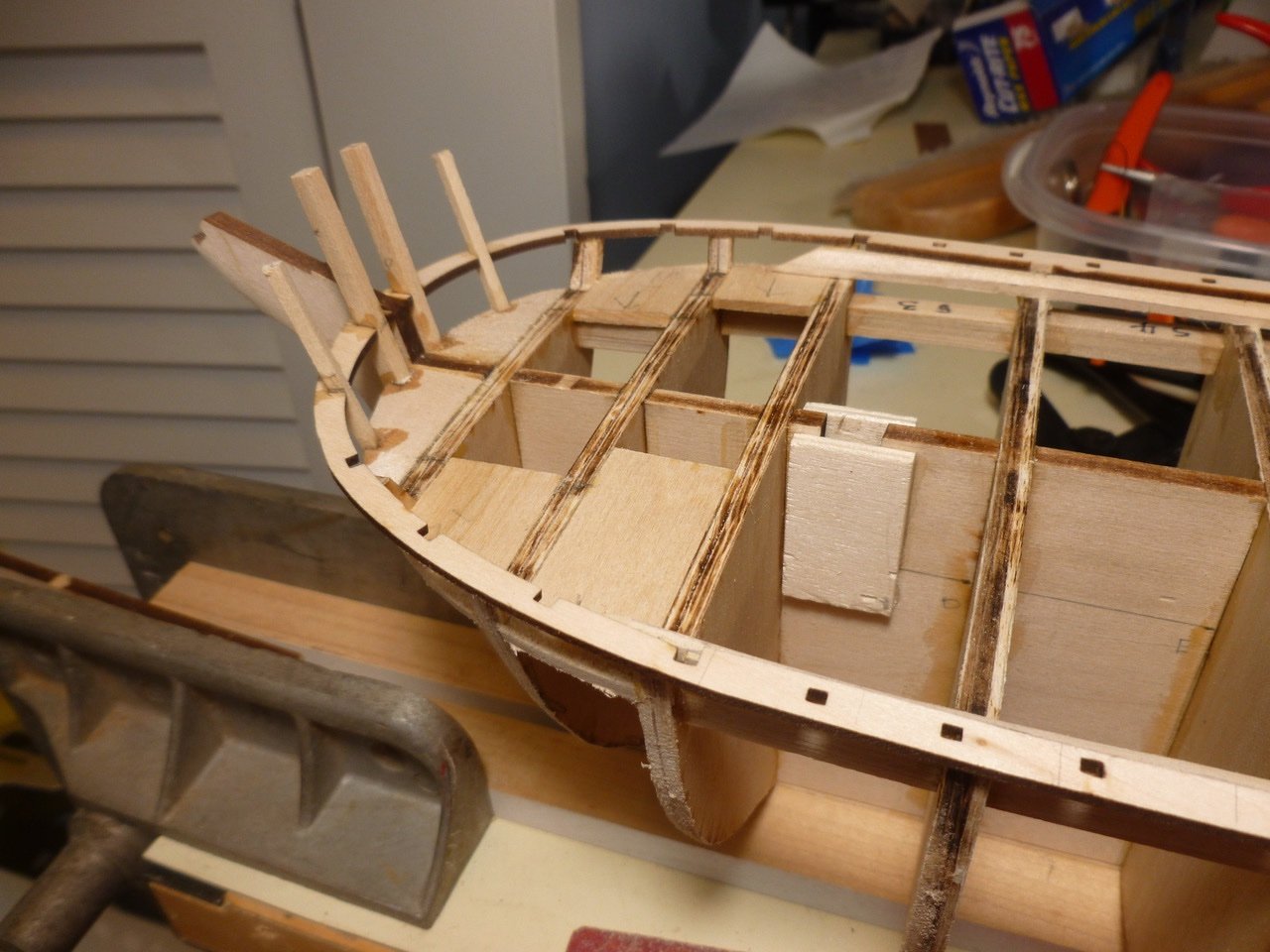
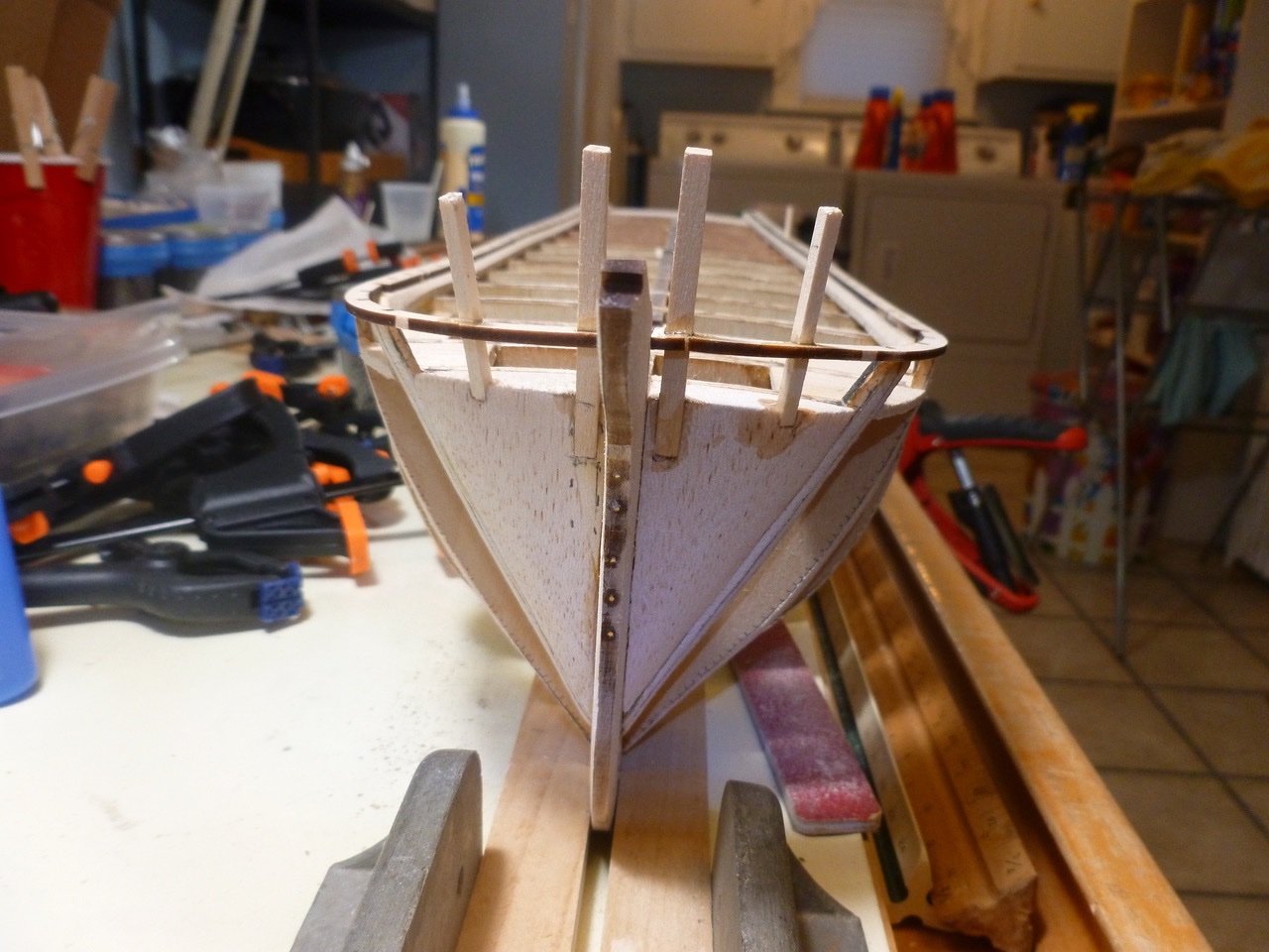
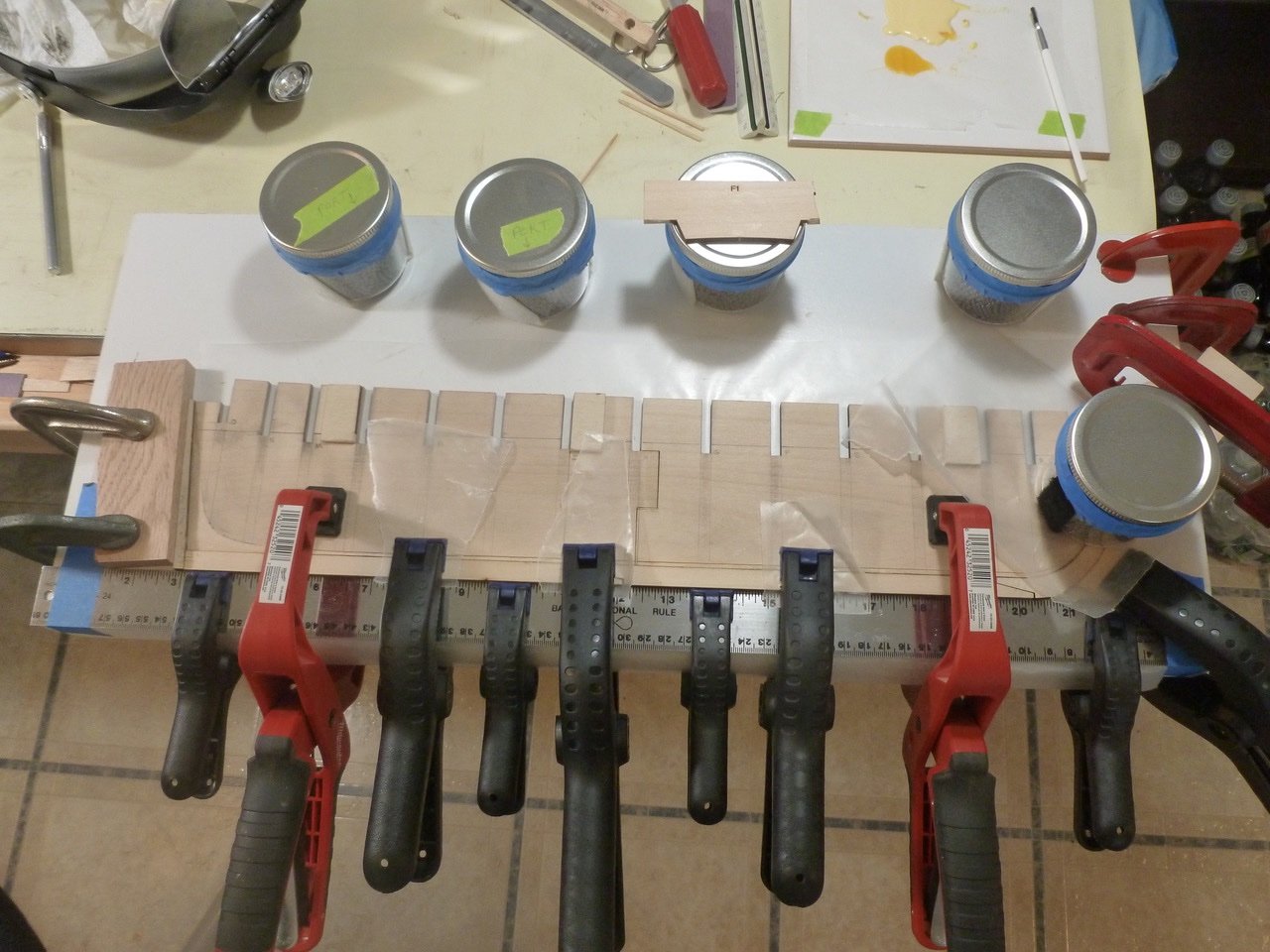
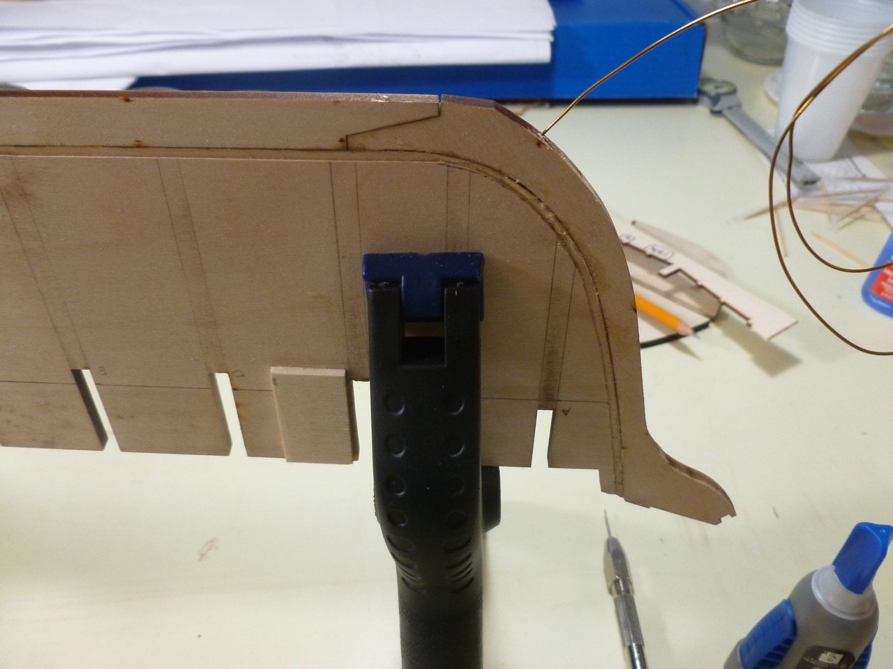
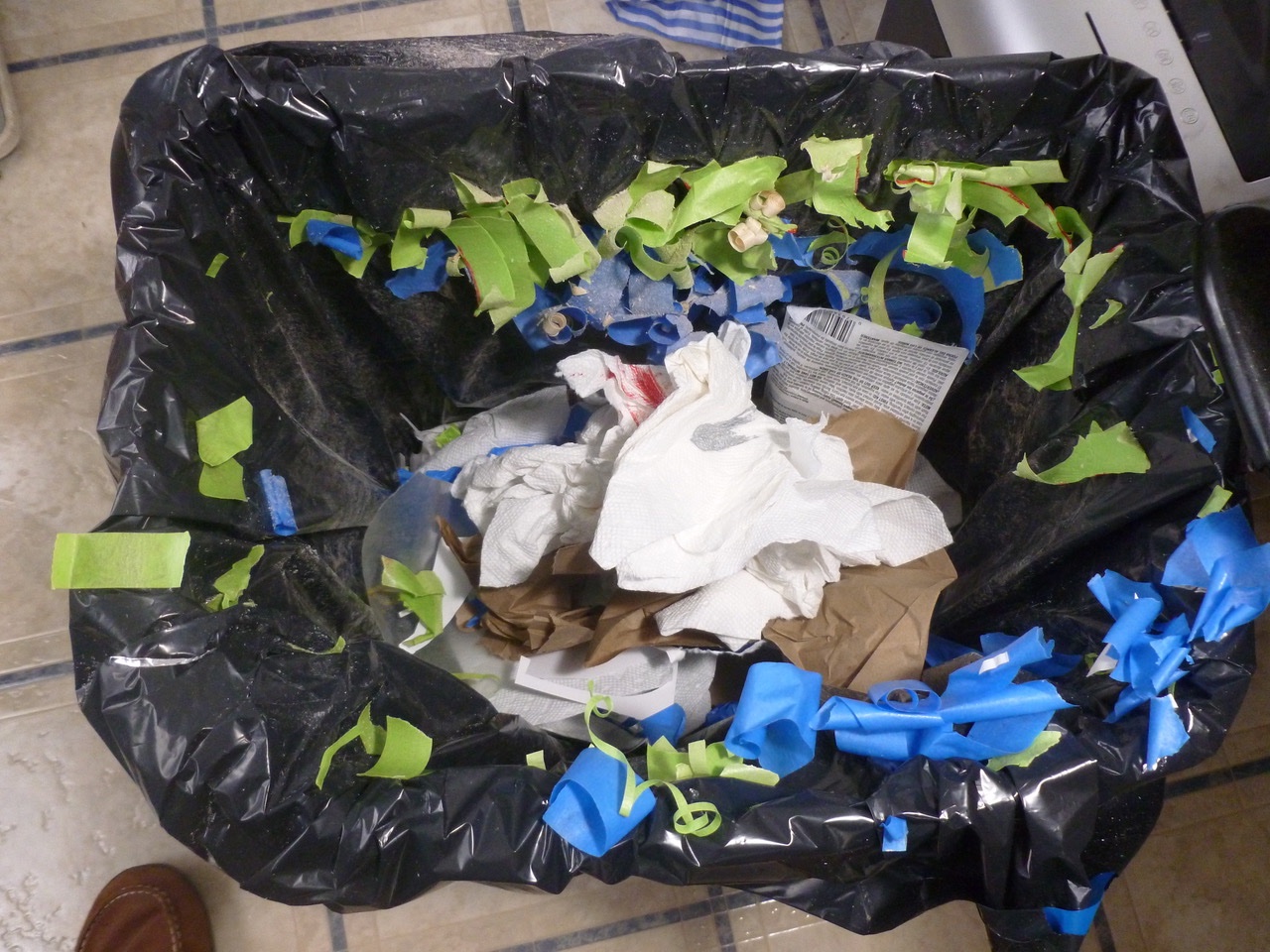
To those who dropped in or gave likes, thank you for your interest and support. Jon, thank you for your kind comments. Your CWM build is coming along very well. I carved and sanded the bow support from balsa blocks. The instructions say the waterway varies in thickness and shape, and at the bow goes from a thick piece to a heavy ceiling. Close study of the drawings shows the waterway following the height of the bulkhead tips. Toward the bow I doubled the waterway thickness with an extra piece along the bottom, then planed and sanded the bottom to follow the rise. I placed a temporary ceiling plank to help guide the waterway notch and taper cuts. The waterway section shows a chamfer along the inboard edge. At the thicker area the chamfer gradually widens. I left a little more width than the drawing shows along the top edge thinking it would be beneficial for planksheer support. Turns out the planksheer has to project so far outboard to show a reveal that it barely sits on the waterway and the extra space along the waterway top is wasted. After installing the waterway I started test fitting the planksheer. This was tricky, to me at least, particularly the part about keeping the outboard edge proud of a not-yet-installed plank below it. I believe I’ll have about 1/32 inch projection beyond he future plank but I also may add a cover strip on the planksheer to get more definition as others have done with their builds. The planksheer is installed with only two mishaps. At the starboard bow one laser cut notch snapped. I was determined to avoid the same problem on the port bow so I snapped the knighthead notch instead. My earlier idea of pre-setting the bulwark stanchions went in the trash when I realized just how many stanchions will need to be adjusted in place to achieve a uniform vertical alignment along the sloping planksheer. Don’t pay any attention to the the man in the slippers behind the curtain. The finished planksheer has a smooth rise except for the scar bump at the knighthead repair, which needs some filing. Before the planksheer work I installed some blocking, actually way too much blocking, for support of decking plank ends. I only hope it doesn’t get in the way of something else down the road. Thanks for viewing. Steve
-
Jon, she’s coming along nicely. Your struggles are paying off. Hang in there. Steve
-
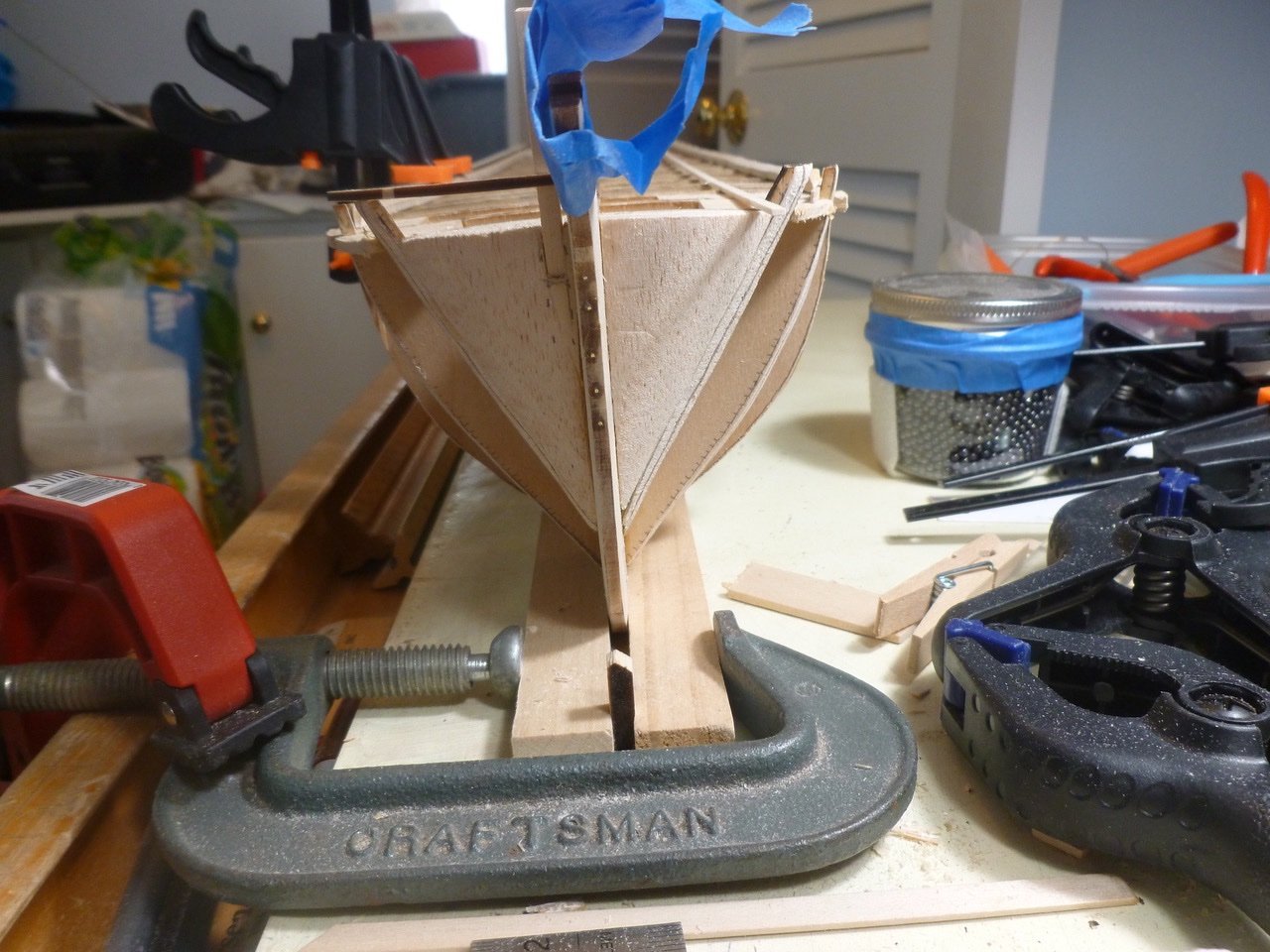
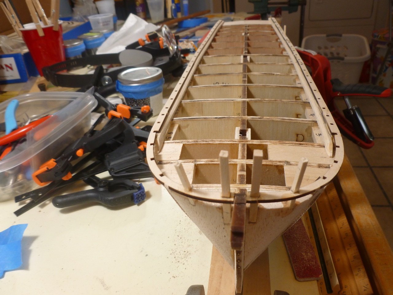
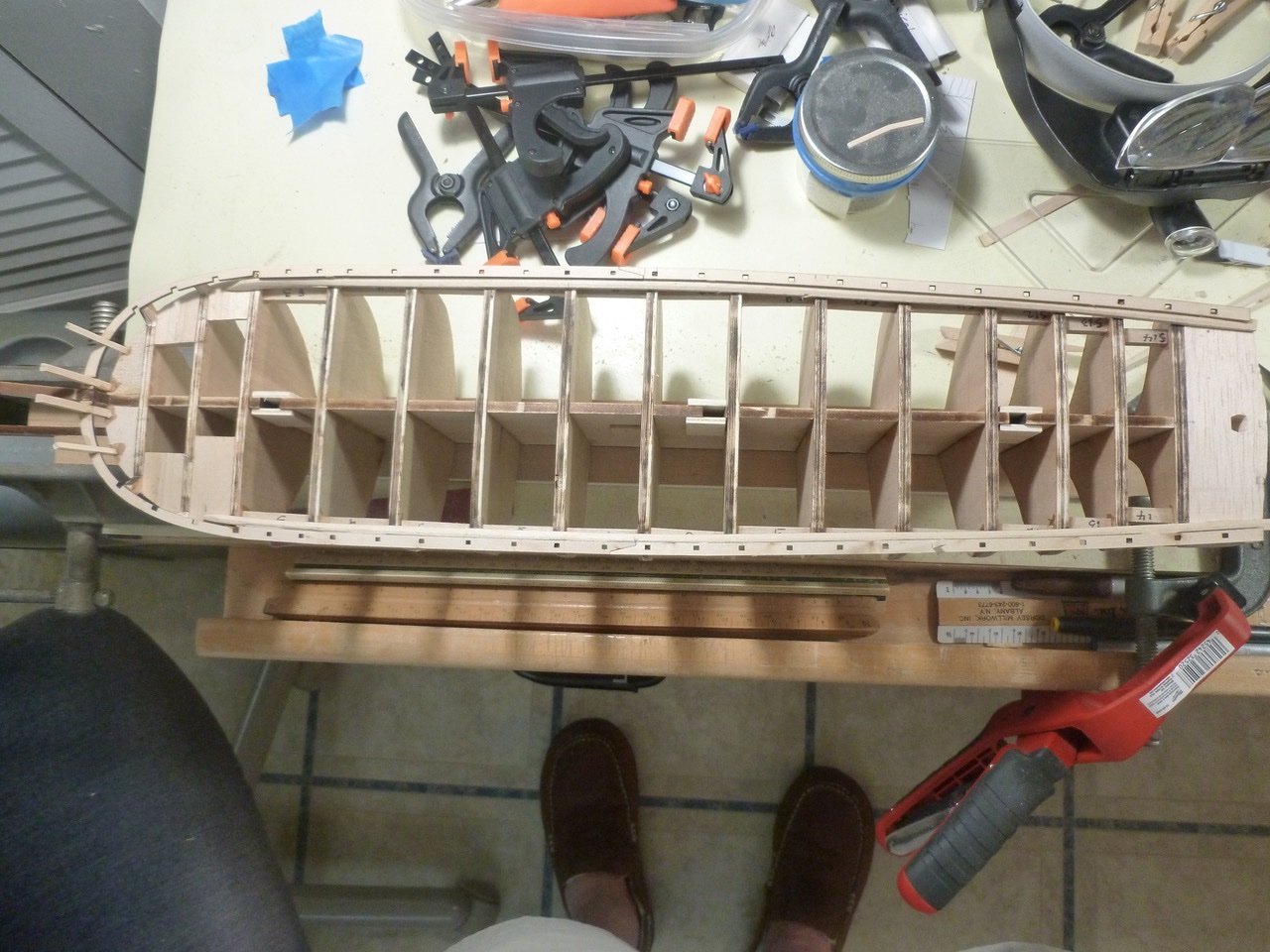
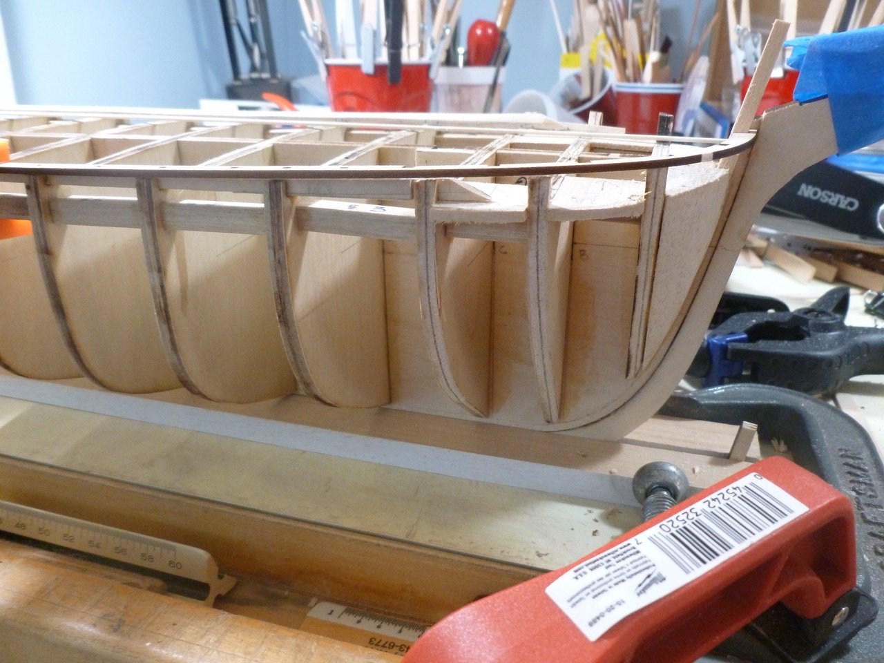
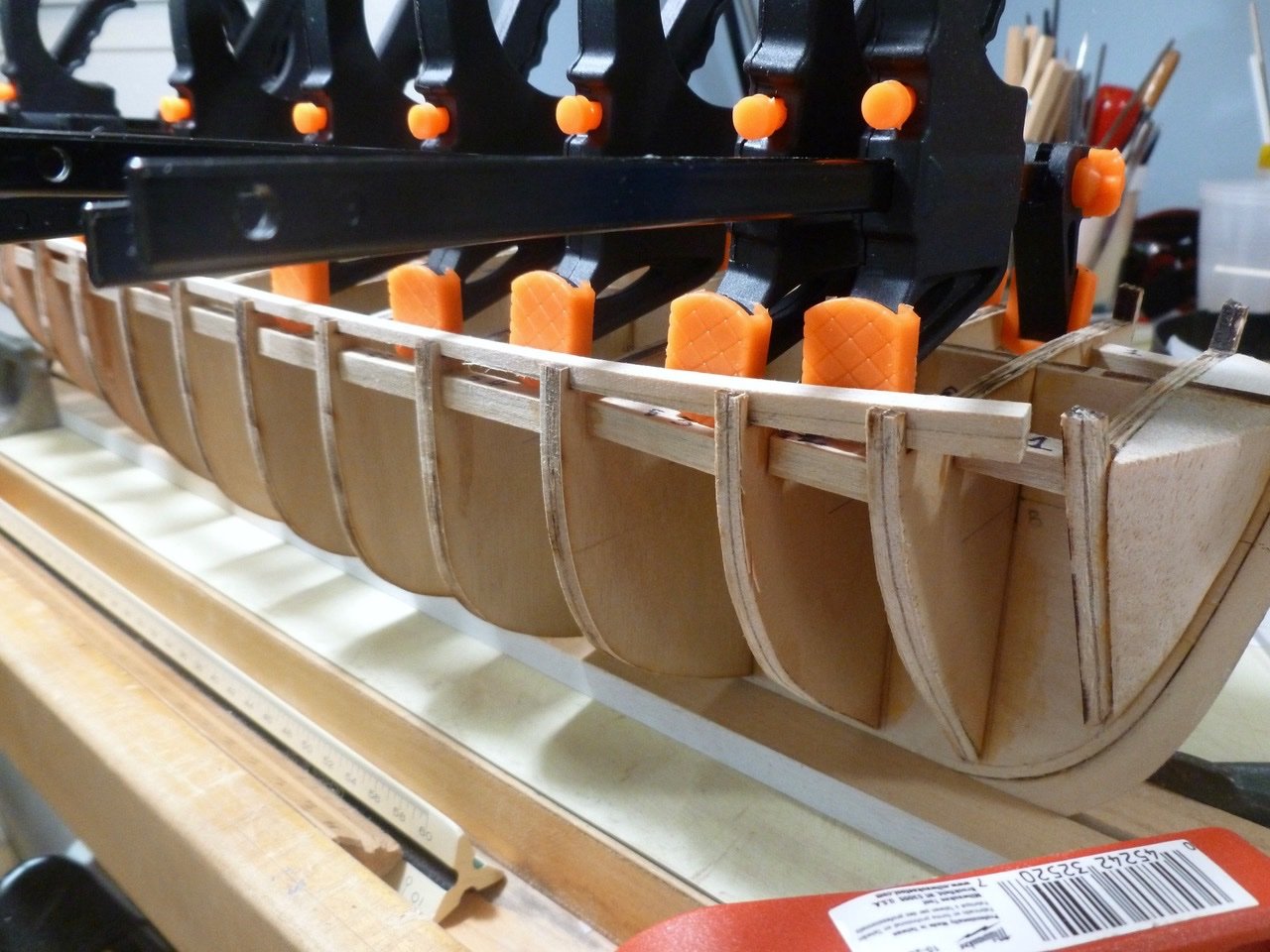
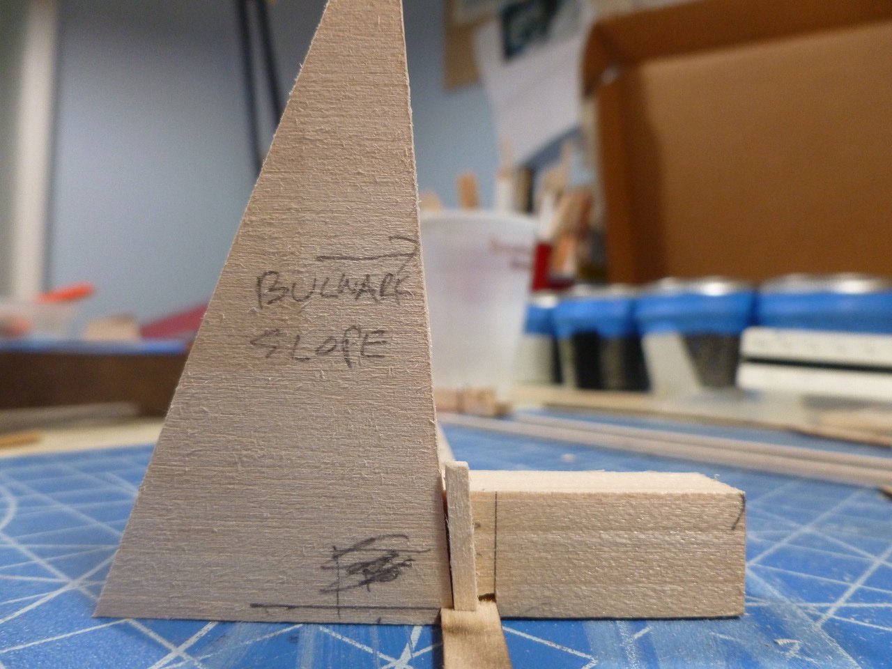
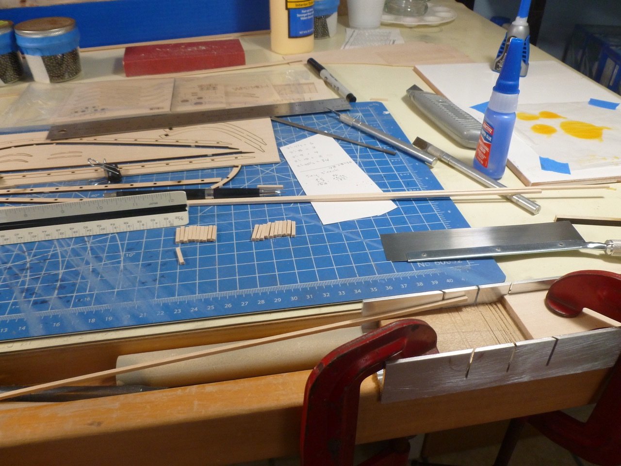
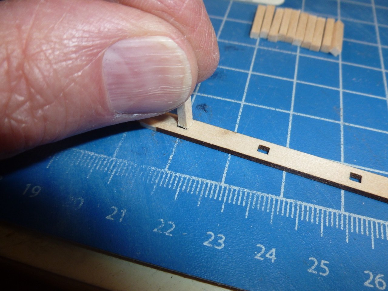
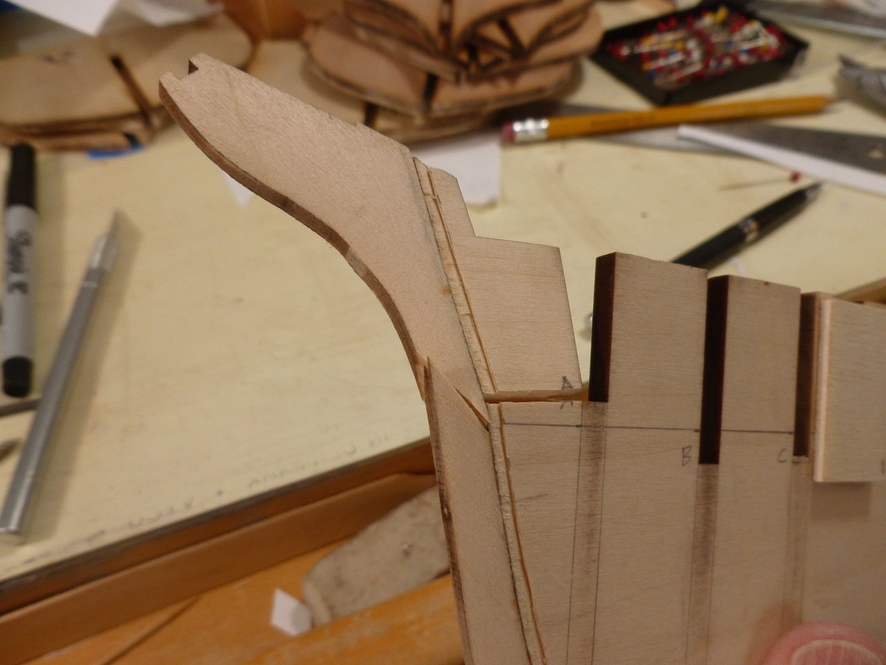
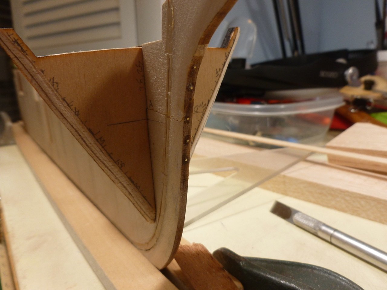
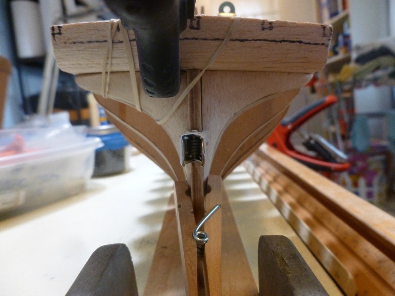
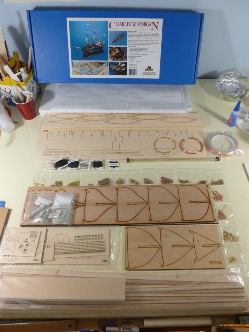
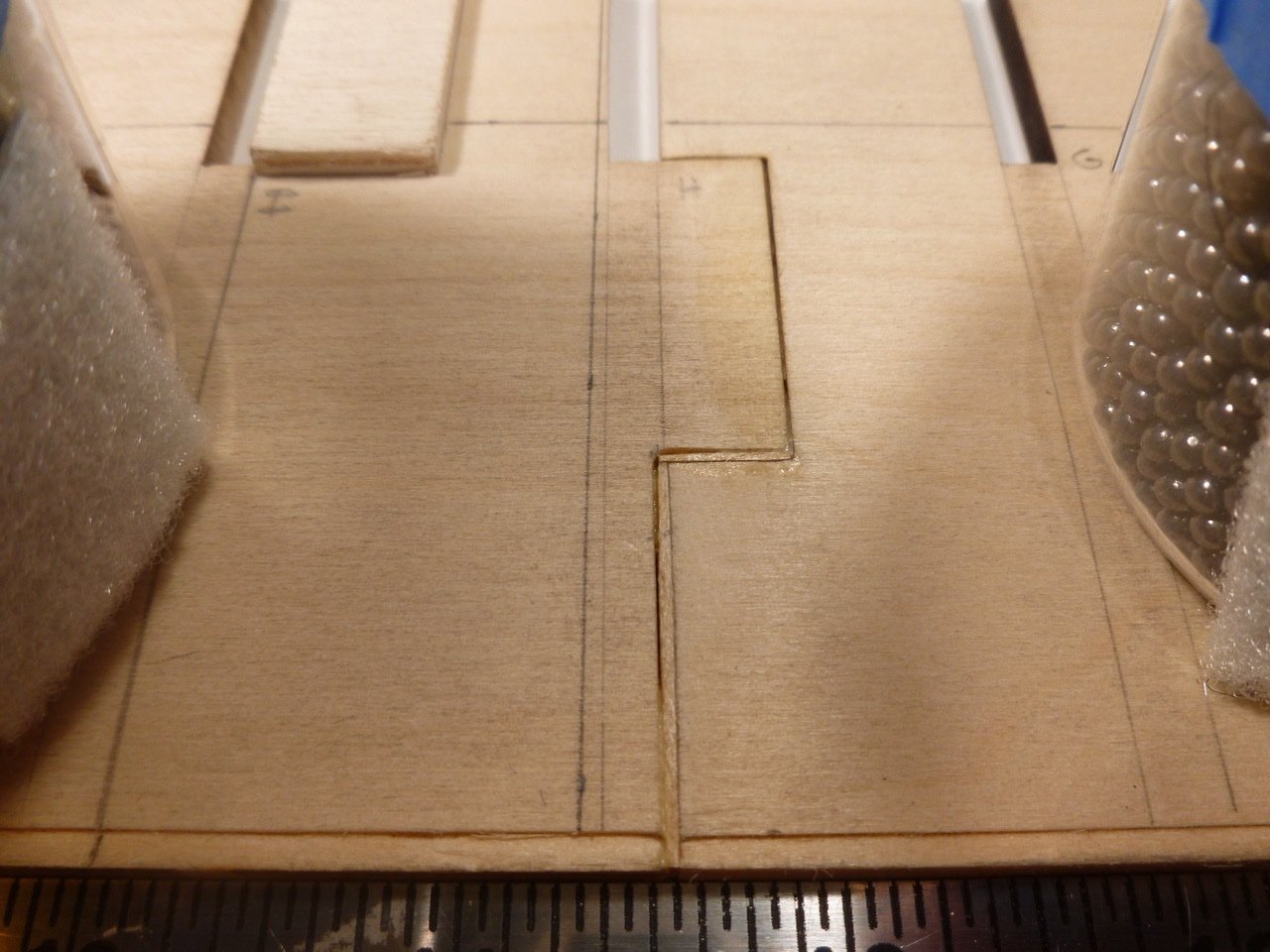
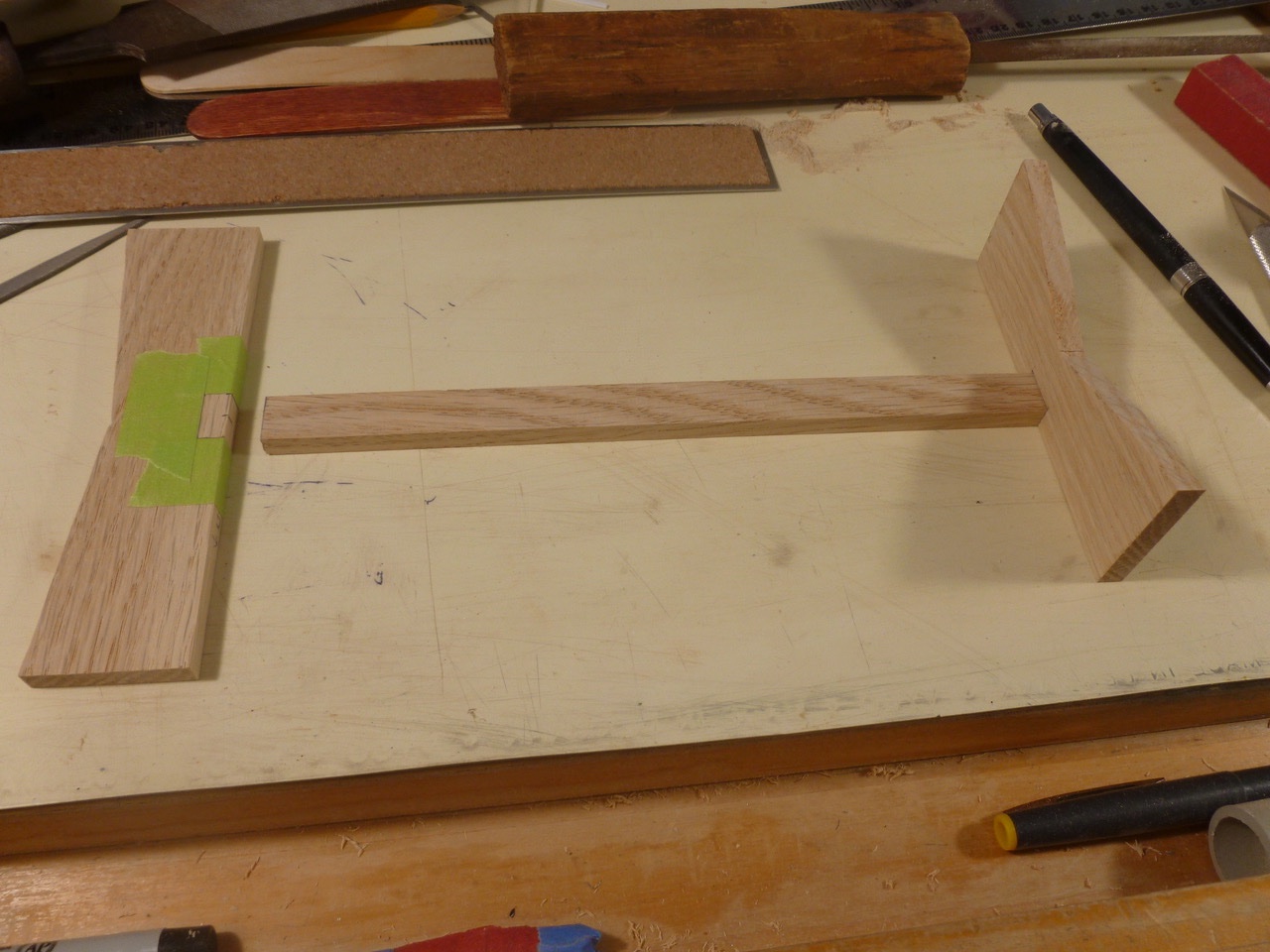
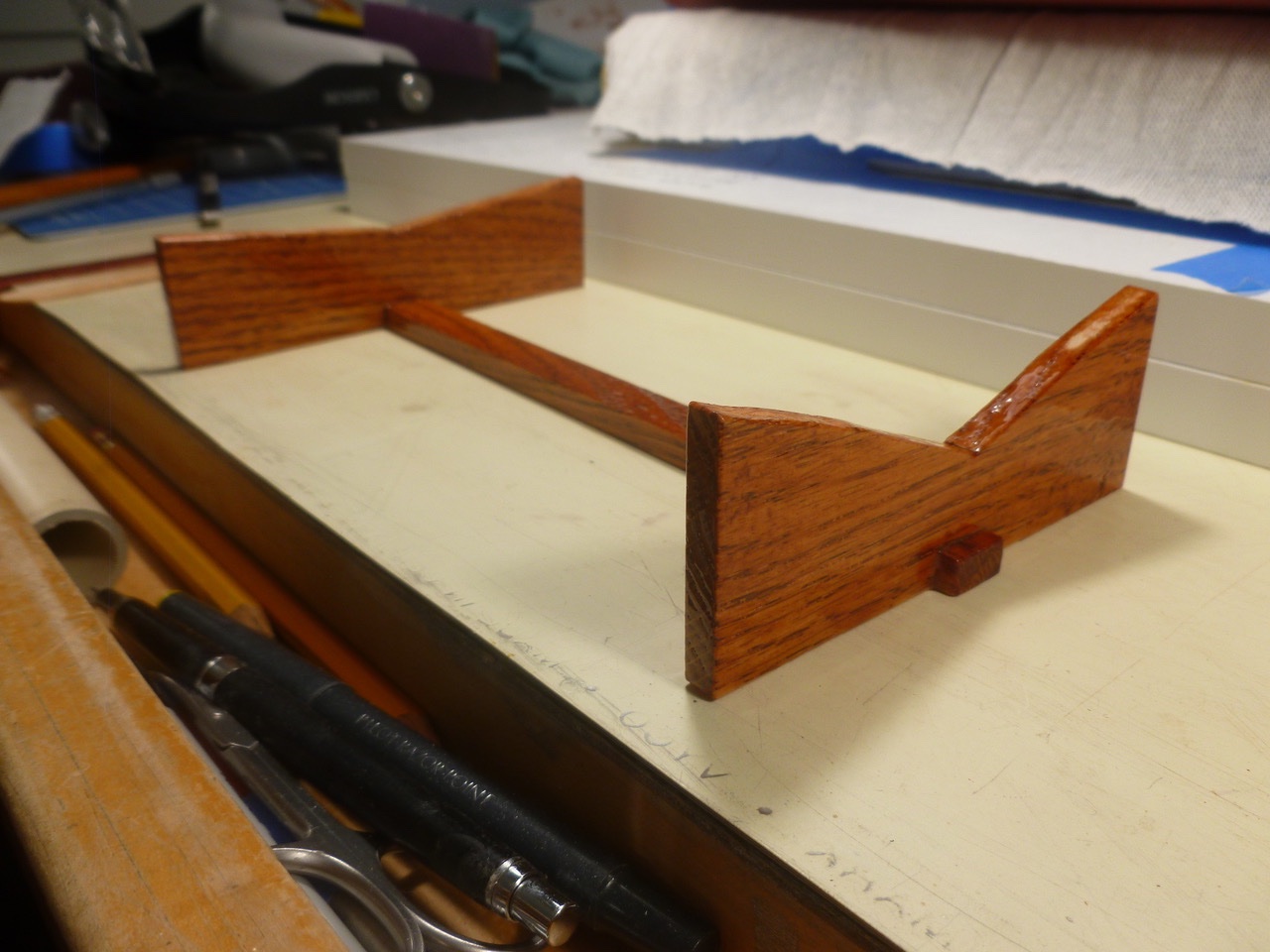
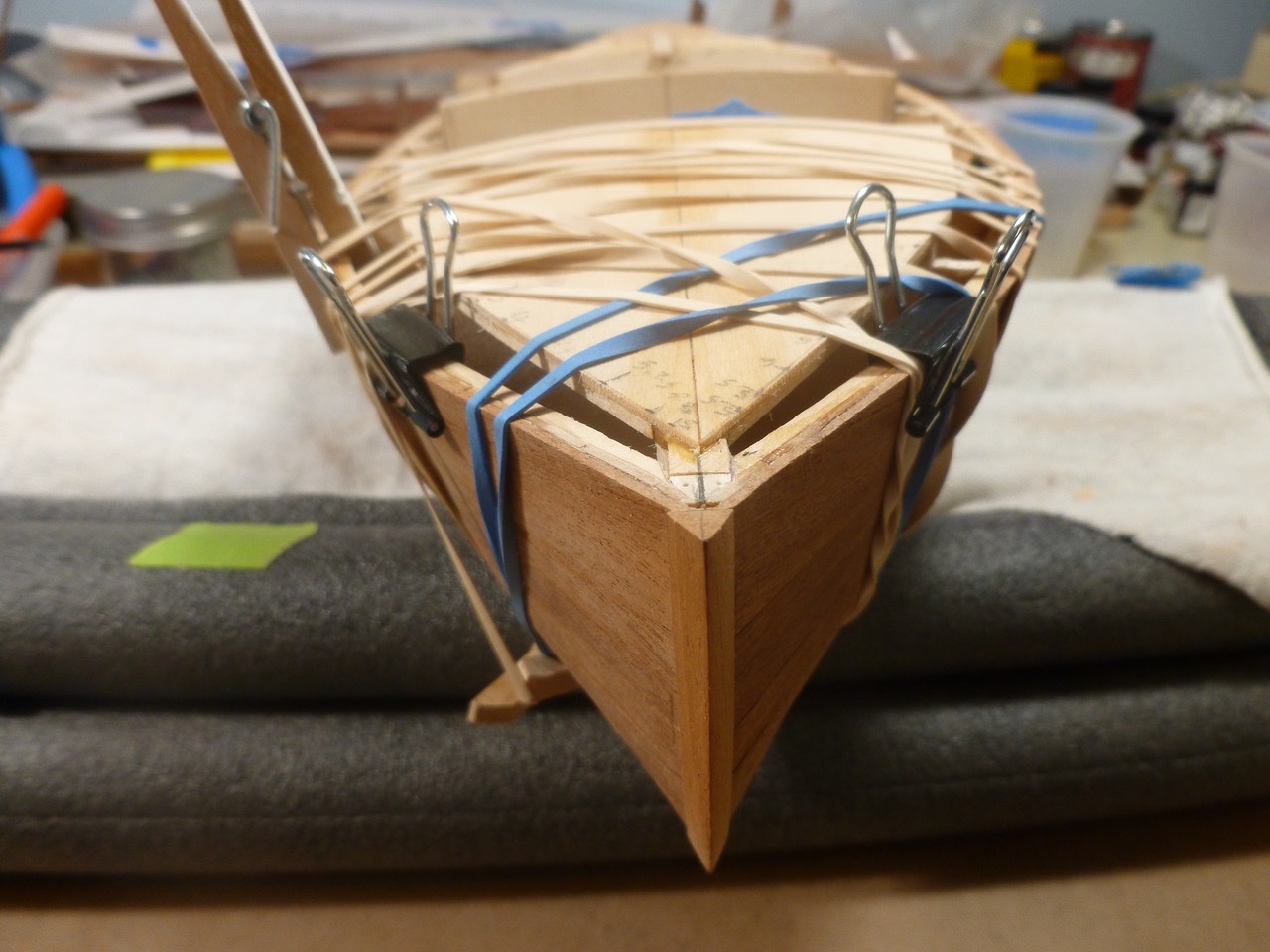
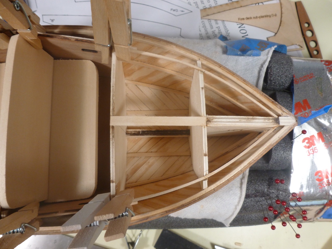
This is a log of the Charles W. Morgan, chosen as an opportunity to expand my modeling horizons, and for no other reason than the Admiral and I took the kiddies to Mystic Seaport over 30 years ago and spent a cold day traipsing around the ship. First, a thank you to those who have gone before. I have learned a lot, seen build quality I can only dream about, and thoroughly enjoyed the consistent thread that combines abject misery with the sheer joy of each challenge met. My goal is maintaining the discipline to go the full journey, which apparently is by no means assured. I’ll skip the unboxing comments other than to say everything was there except for the ship’s bell, which was forwarded in short order following my request to Model Expo. I chose to cut the rabbet prior to assembling the keel parts. An X-acto no. 17 chisel blade was helpful in tight areas. The jars of shotgun pellets, which served as ballast on a prior RC build, came off the shelf as a counterbalance to allow extending my work board over the edge of the desk. This gave clearance for clamps. The laser cut joint required shims. Brass wire and medium CA pinned the parts together after the glue set. The keel clamp is two wood strips anchored at one end by an old saw vice, and at the other by C-clamps. While massaging the bulkhead slots I discovered that all the keel slots were cut with what appeared to be an out of alignment laser (?) which prevented the bulkheads from fully engaging the keel slots and which twisted the alignment. If left un-filed this could have resulted in bulkheads out of square with the keel. To help maintain alignment I filled the outboard bulkhead spaces with 1/4 inch square strips of lengths to match the bulkhead spacing along the keel centerline. Bulkhead setting was assisted by a small framing square, age unknown. A test fit showed a reasonably straight start. Reading ahead the instructions indicated that the bulwark stanchions should be installed with a slight tilt per a detail drawing. This looked to be a roadblock so I cut a bunch of stanchions and punched out a piece of the plank sheer to review options. The first issue was that the 3/32 inch stanchions didn’t fit the 3/32 inch holes in the plank sheer. Each stanchion needed a slight trim (28 passes) on two sides at the sanding block. Now, how to set a tiny stanchion vertical in one dimension and angled in the other. My first thought was to push a scrap of wood up against the bulkhead, and align the stanchion with that. But that only works at a bulkhead and is awkward at best. The current thinking is an alignment jig (the stanchion is not yet glued in the photo). It fits over the plank sheer, has one surface for vertical alignment, and an edge set at the stanchion angle. Once the stanchion bottom end is trimmed and the stanchion hole is filed at one side, the stanchion is placed in the hole. After setting the jig the stanchion is secured with CA. Using this method it appears that the large majority of stanchions could be pre-set before the plank sheer is installed. Exceptions would be at the bow and stern where the plank sheer rises. Seems like a plan but we’ll see how reality and the CWM rabbit hole impact it. If you see any deal killers please chime in. Then the stem broke. Actually it wasn’t the first break, which occurred when I breathed on one of the mast slots in the keel. That was fixed with cover plates on both sides of the mast slot, along with plates on the other mast locations. While mucking about with the stanchions an errant elbow trashed the stem. Part one of the fix, after gluing the parts, involved more pins drilled as deep as the little bit could reach. Part two will be the supplemental support provided by the bow filler blocks which are being fabricated. I’m hoping there will not be too much tension on the stem during rigging, but I have no experience with long bowsprits so we’ll see how it goes. The counter and stern support blocks are installed. Reminds me of my first day in high school. After we were dismissed one of the school’s finest demanded that four of us climb into his convertible and squeeze down on the floor. He passed over one newbie who had a head full of shaving cream (“I ain’t gettin’ no lanolin on my tuck and roll!”) He then chauffeured us about 10 miles out of town and onto a deserted road in the woods where he dropped us off. When we asked which way was home he said “You’ll figure it out.” Thanks for viewing. Steve
-
Chuck,
I posted a log of the Zebulon B. Vance on MSW about six years ago. The build was based on a kit from Deans Marine. While looking for some new kit info I sent them a few pics of the Vance. They have asked me if I would set up a Vance log on their site. Since the whole issue of what can't be shared is a bit mystifying to me I would appreciate it if you would clarify or point me in the direction of a previous ask/answer. I read the guidelines but am unclear on whether sharing of my own copyrighted photos and text is permitted or not. Thank you, and thanks for everything you do to educate the membership.
Steve Finkle
-
Jack, I just found this. What a cool figure! Looks just like real fabric and metal. Well done! Steve
-
Todd, thank you. Having never done a finish like this before, I was amazed at what 9 coats of spar urethane can do with scuff sanding between coats. gak1965, thank you too. It was actually normal gestation, about nine months from start to finish in November 2022. I hesitated putting it up in real time since I had great fear that the woodwork and finish might end up a total muck. Steve
- 40 replies
-
- 1
-

-
- BlueJacket Shipcrafters
- Chris-Craft
- (and 2 more)
-
Brings the phrase "busier than a one-armed paper hanger" to a whole new level. Fantastic work. Thanks for sharing. Steve
-
To those who dropped in or gave likes, thank you for your interest and support. To all who hit the WOW! button, double thanks. I’ll never tire of it. Roger, Gary, Paul, Nic, Jack and HOF: Thanks so much for your kind comments and enthusiasm. They are at once humbling and energizing to get cracking on the next build. A shout out goes to Bluejacket for a high quality kit, great customer support and very quick order fulfillment. I often refer to the tips in their online library of newsletters at the website. Postscript: An irony of the build is that the “clear” spar urethane finish got a slight amber tone when cured, which gave a nice warm finish to the woodwork, but also added a slight tone to the caulk lines I so carefully resurfaced back to white during the build. The good news is that the urethane should help protect the caulk strips. Lessons, lessons, lessons - they are what makes shipbuilding so much fun! Thanks for viewing. Steve
- 40 replies
-
- 3
-
-
- BlueJacket Shipcrafters
- Chris-Craft
- (and 2 more)
-
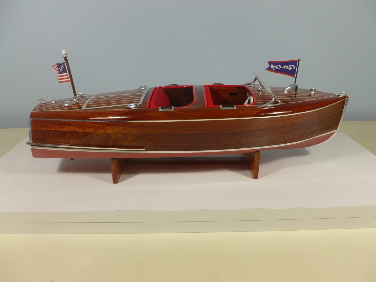
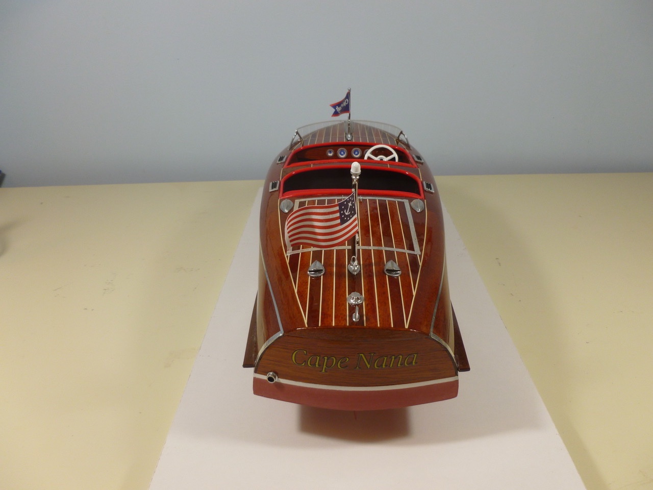
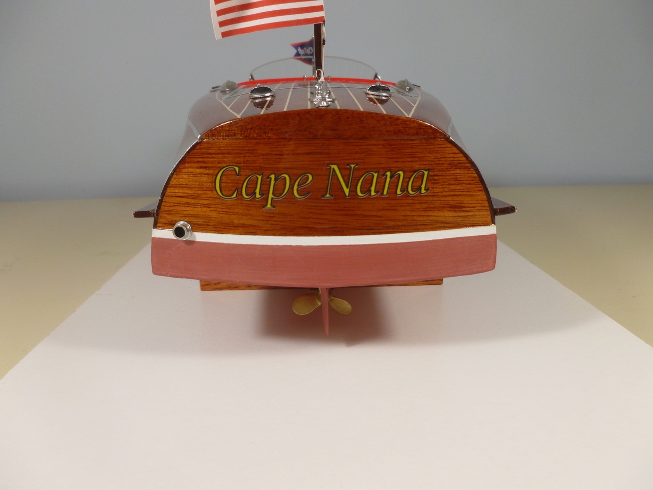
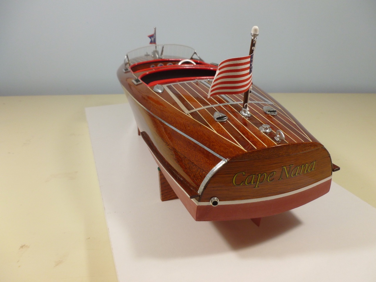
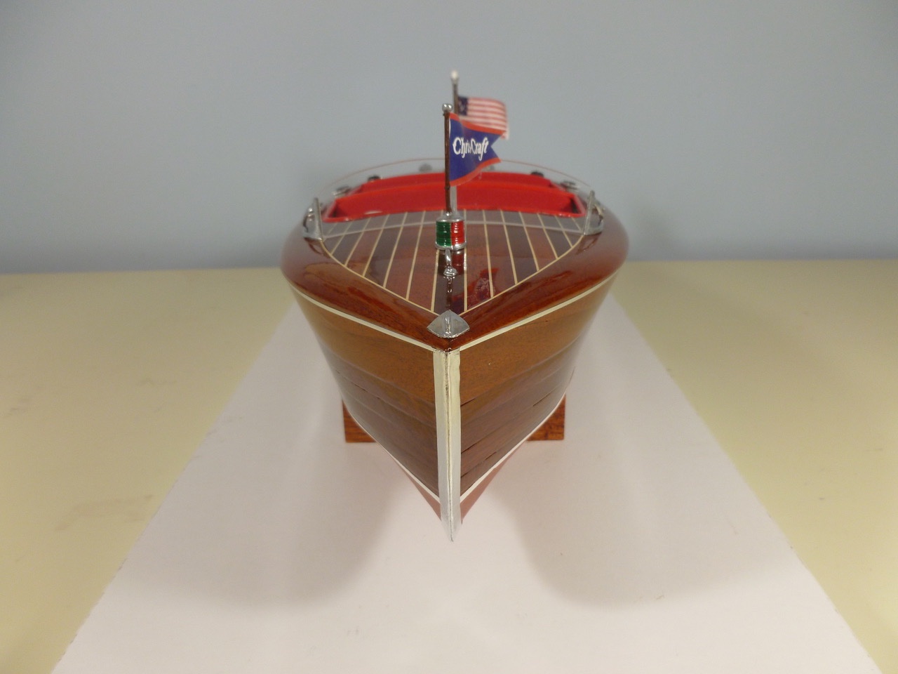
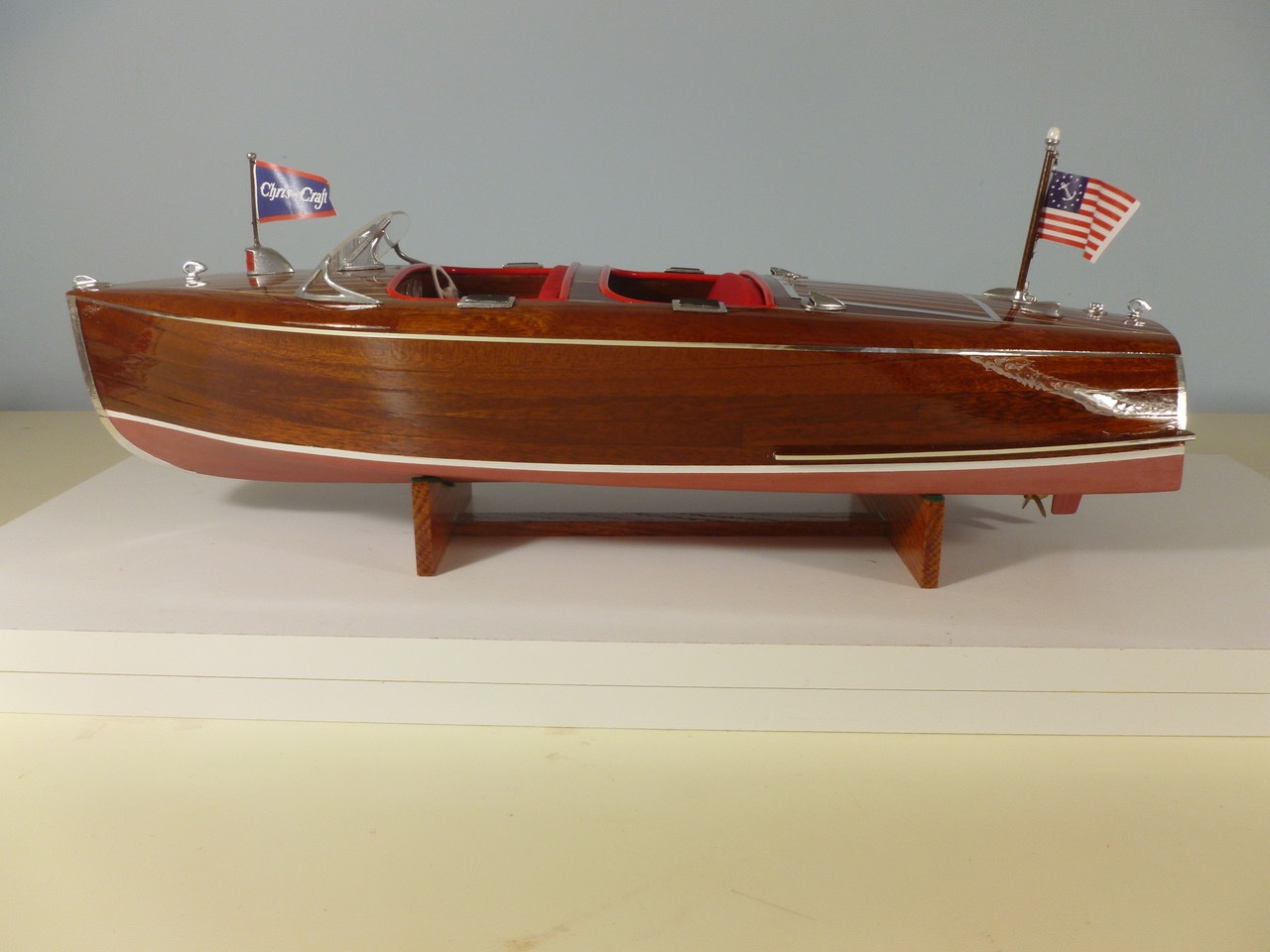
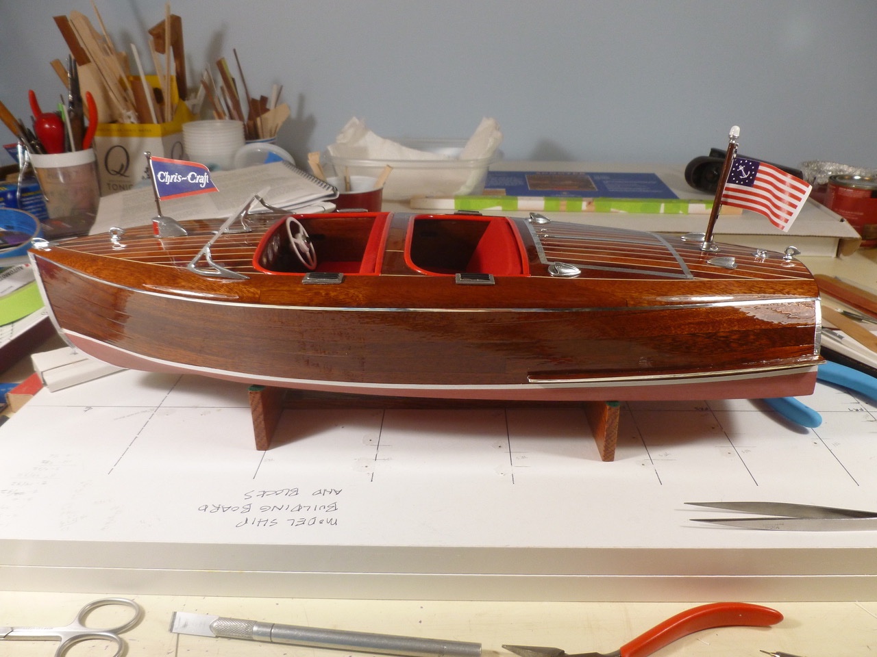
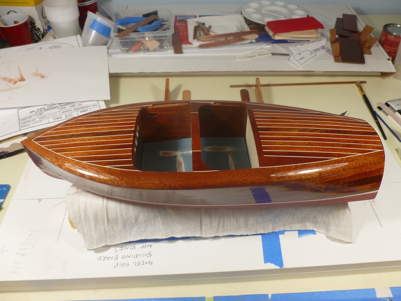
To those who dropped in or gave likes, thank you for your interest and support. Knocklouder, thank you again for your ongoing interest and your kind comments. I am happy with the result. I proved to myself that I am capable of doing a double planked, bright finished boat and I thoroughly enjoy every opportunity to look at it. Below are the remaining beauty shots. A heart stopping moment was when I installed the aft deck vents backward (open face forward). A fast chisel and touch up urethane were aided by the fact that the vents almost completely covered the damage by slightly altering their fore and aft position. The name pays homage to the Admiral’s lofty perch as Nana to the grandchildren, and to her love for Cape Cod where we have vacationed for many years. The custom decal came from a local printer, using a file I emailed to them. See, there really is a starboard side to the boat. Thanks for viewing. Steve
- 40 replies
-
- 10
-
-

-
- BlueJacket Shipcrafters
- Chris-Craft
- (and 2 more)
-
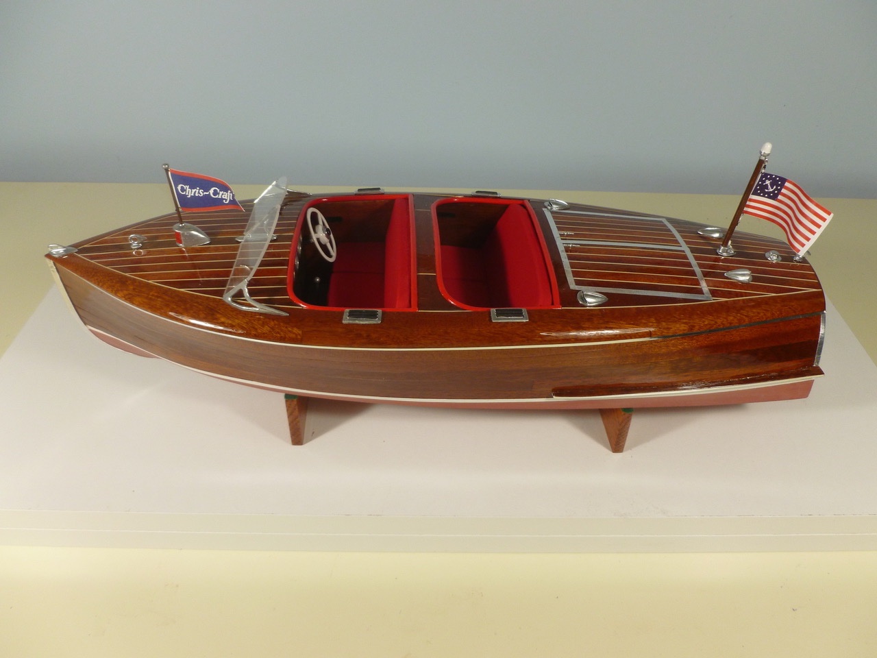
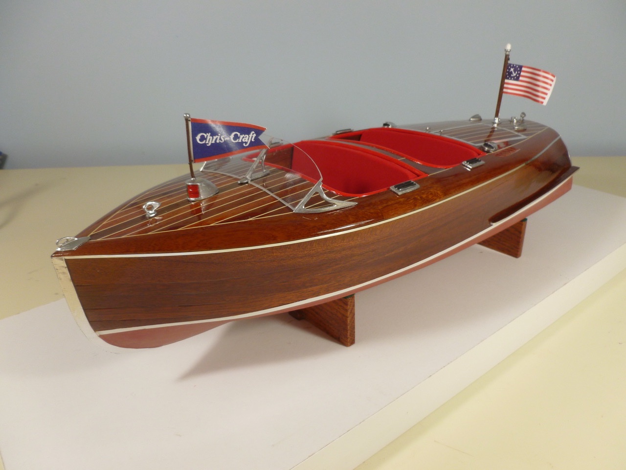
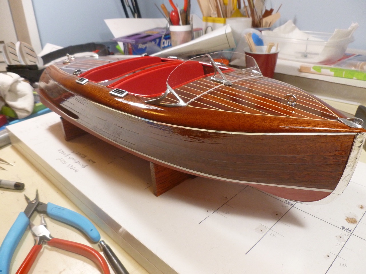
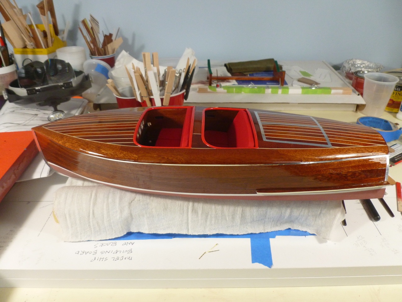
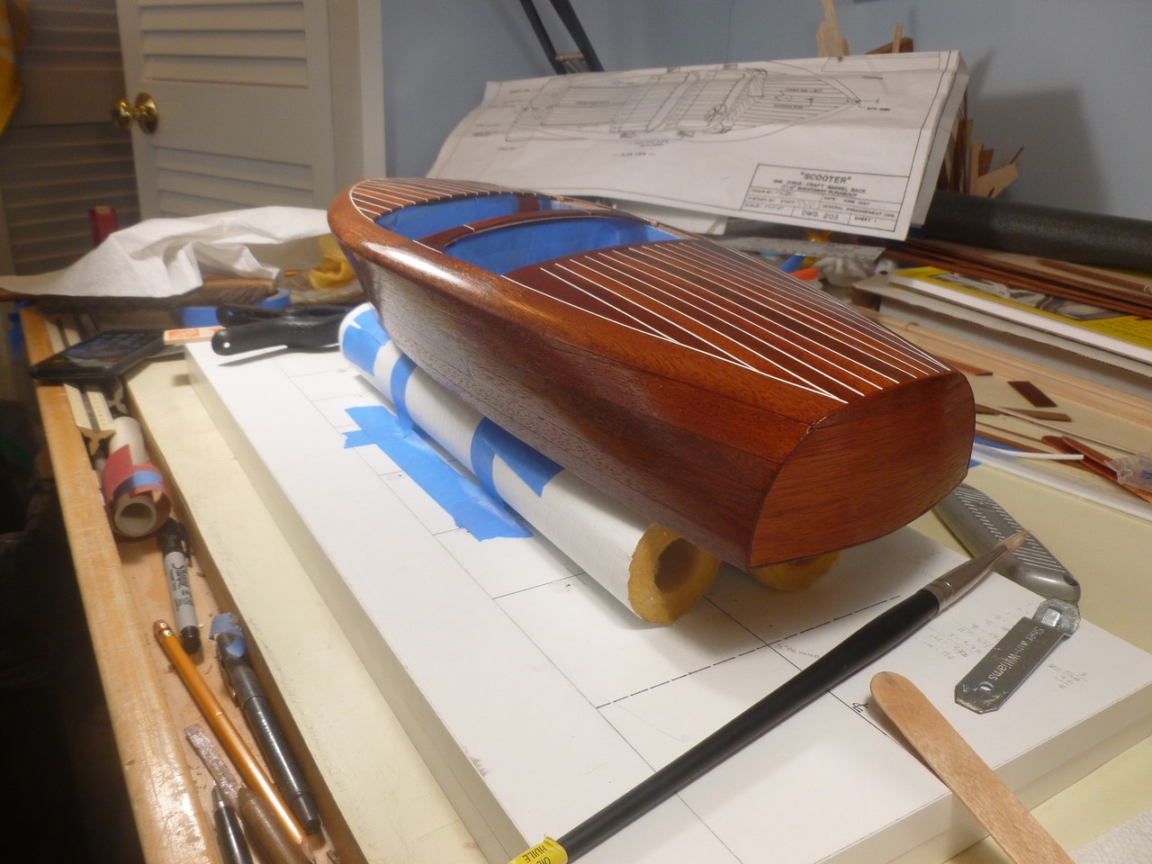
To those who dropped in or gave likes, thank you for your interest and support. To all who have stuck with me since the beginning, thank you so much for taking time out of your days to share in the experience. And now some beauty shots. As I was completing the spar urethane I contemplated trying a cutting and polishing effort using automotive products. I purchased a bottle of each, but when I tried it on a plank cutoff I found it left a slick surface that nothing would stick to. Abandoned that idea. The unpolished urethane will be easier to touch up. And without further adieu, More to come in next upload. Thanks for viewing. Steve
- 40 replies
-
- 3
-
-
-
- BlueJacket Shipcrafters
- Chris-Craft
- (and 2 more)
-
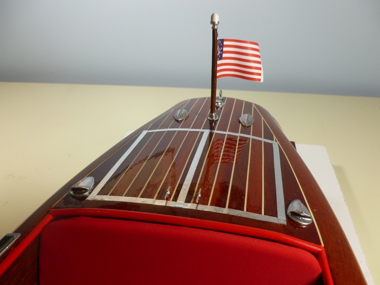
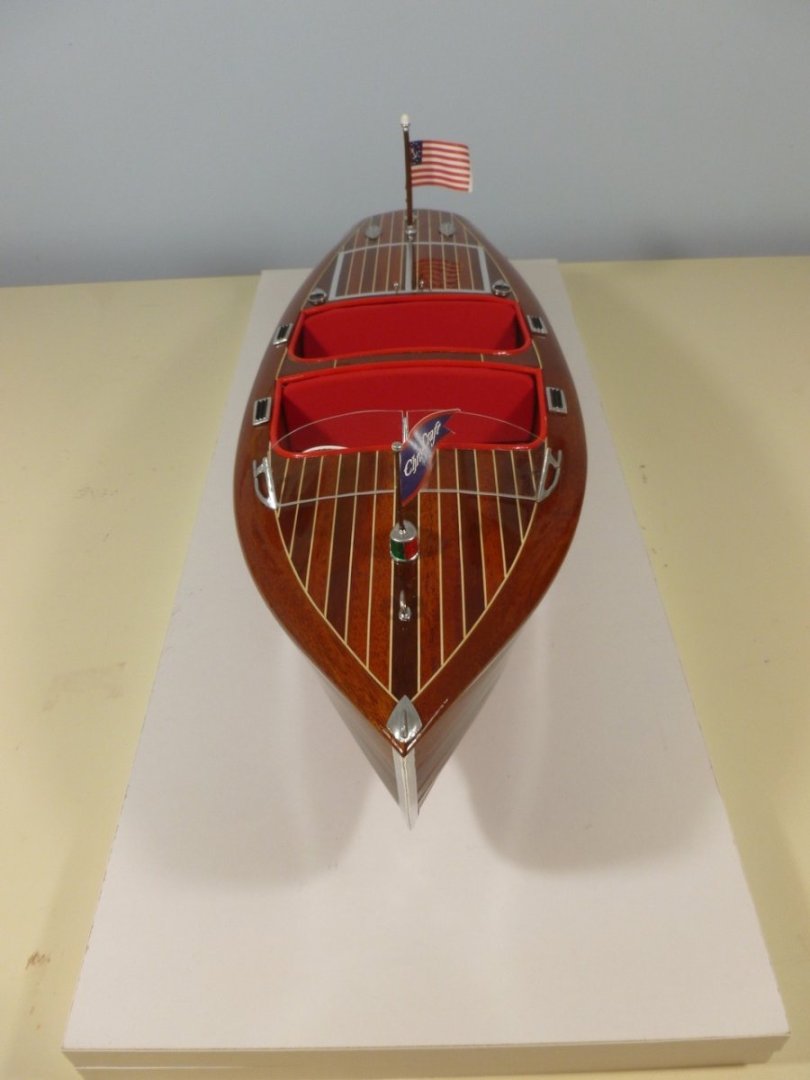
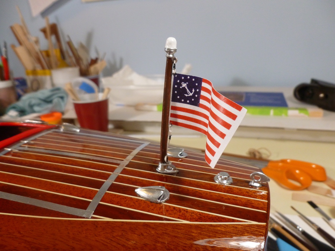
To those who dropped in or gave likes, thank you for your interest and support. The installed windshield is the child of the two types that appeared to be offered for the barrel back. It has the framework of the standard windshield, which came to a point in the middle, but the straight alignment of the “Bugatti” style optional windshield. More by accident than design. Cushions were finally placed into the front cockpit. Flags came in the kit, along with a helpful instruction to wrap them around a dowel to give them a wave. Worked great. Metal bits were installed on the deck after a few coats of chrome silver paint and a little black at the step inserts. I wasn't ready to tackle chrome plating, partly due to cost and partly to lack of enthusiasm. My excuse is the chrome silver is more subtle. Thanks for viewing. Steve
- 40 replies
-
- 6
-
-
- BlueJacket Shipcrafters
- Chris-Craft
- (and 2 more)
-
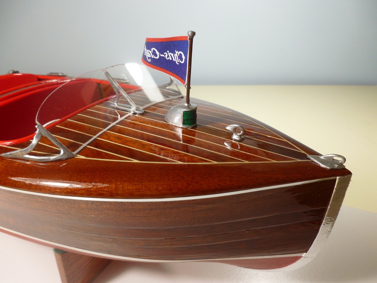
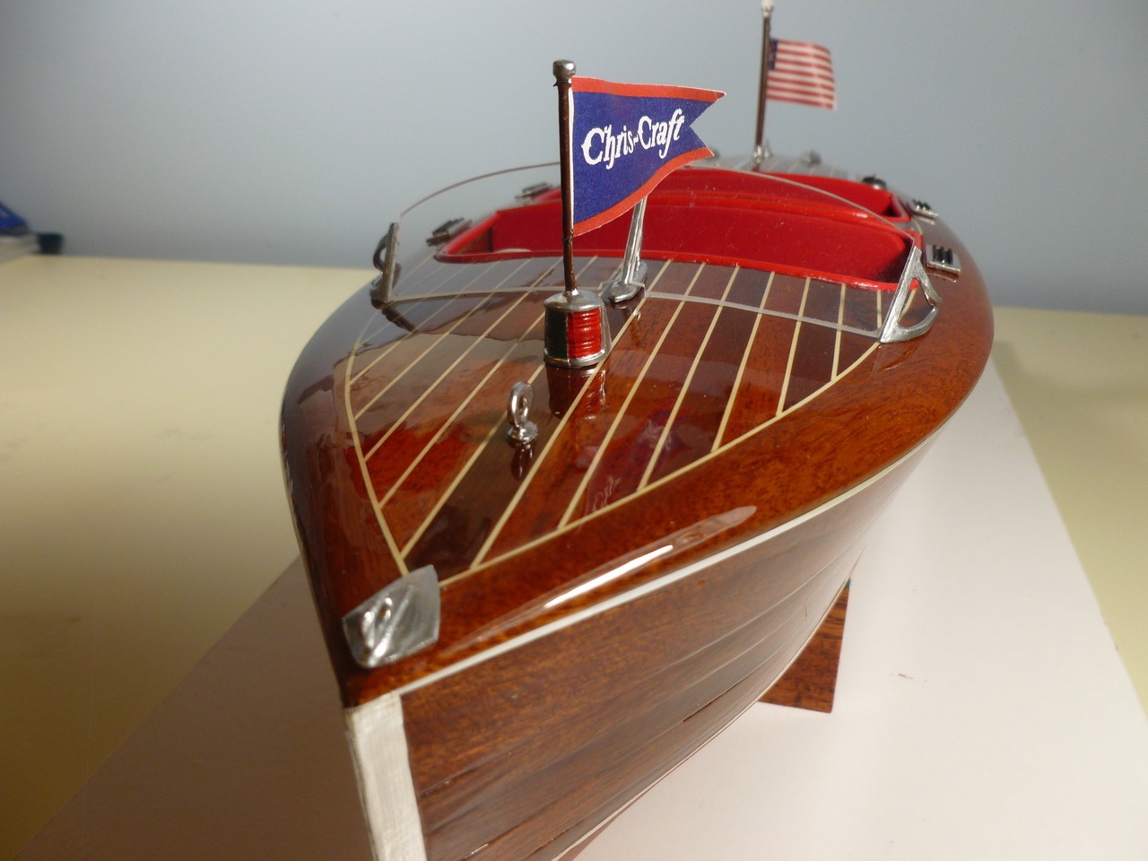
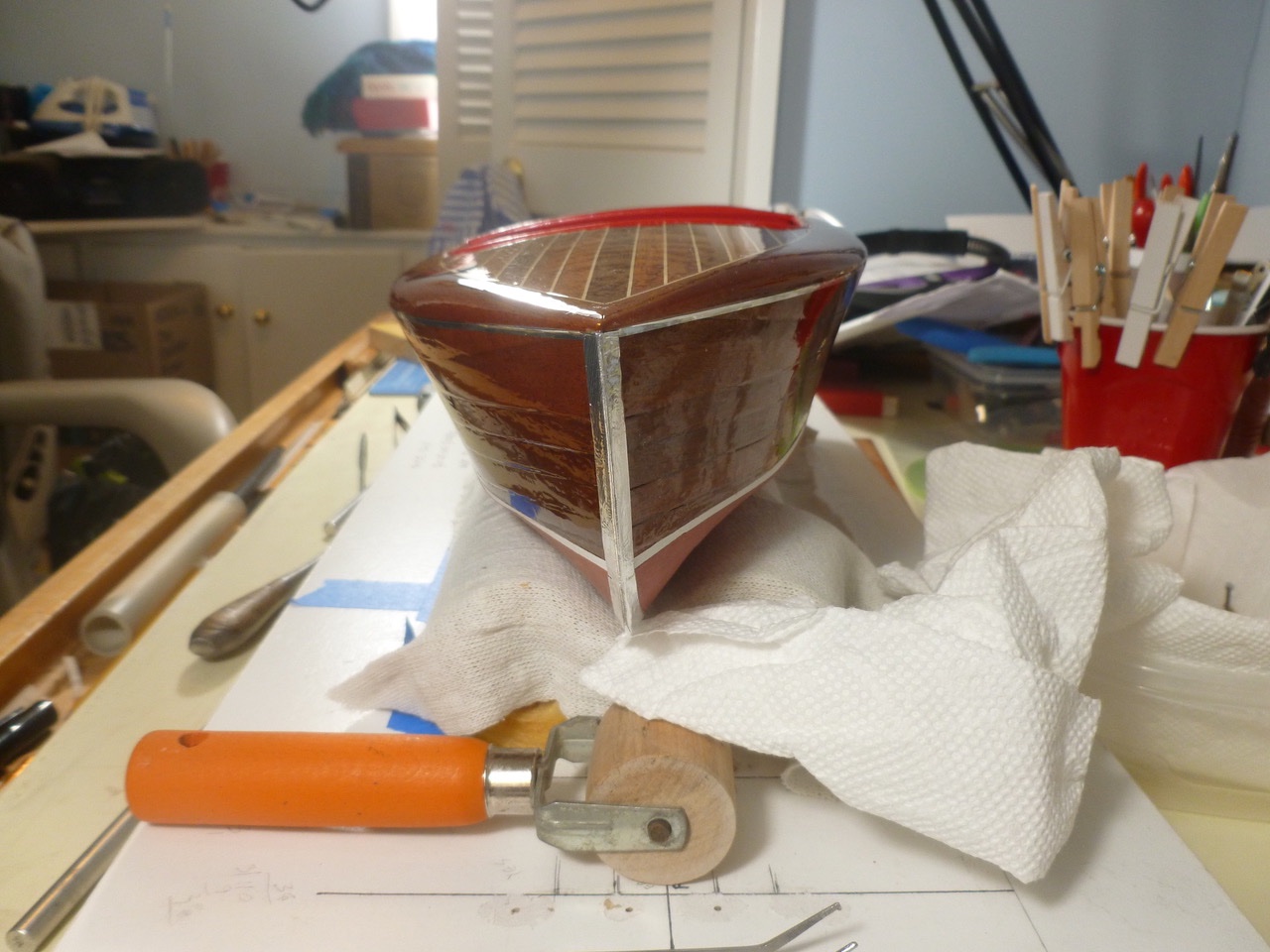
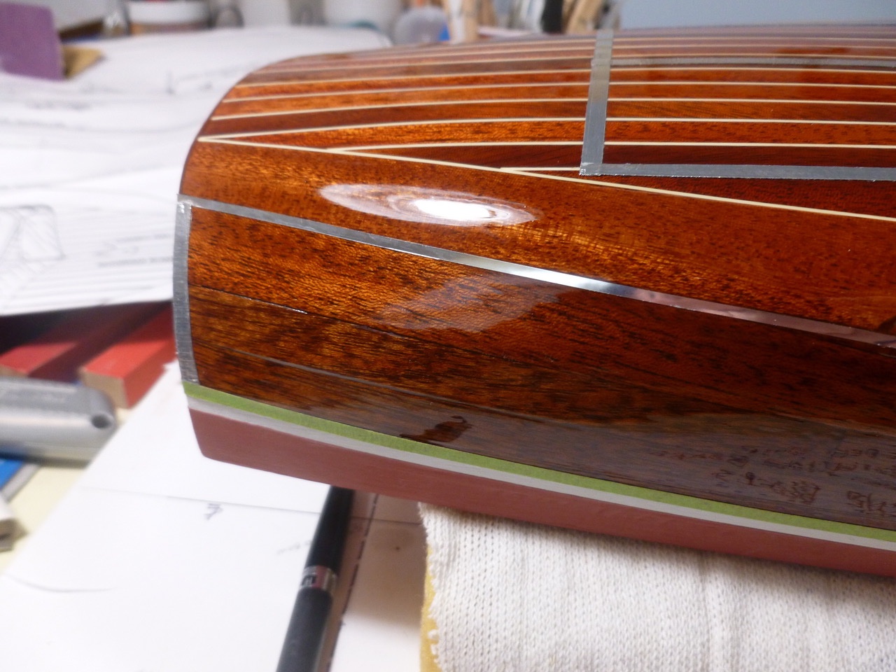
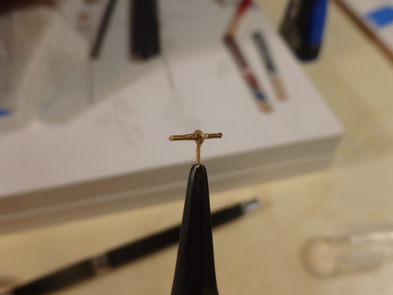
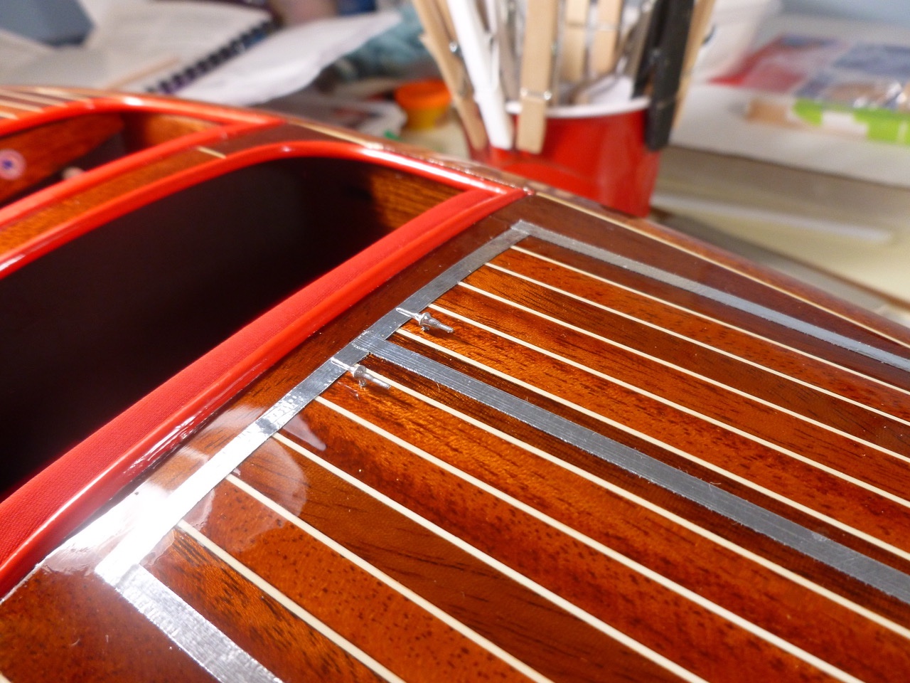
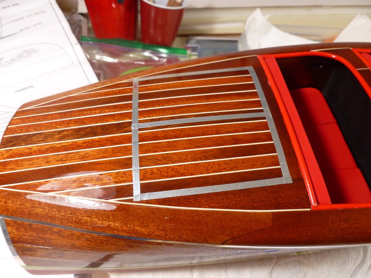
To those who dropped in or gave likes, thank you for your interest and support. The kit includes a piece of self-adhesive chrome to simulate the chrome plated work at the bow, stern and around the hatch cover. A wallpaper roller helps burnish it in place. The kit also includes a small square mahogany strip to hide the joint between the sheer planks and the covering boards. The boat pictures online typically show a chrome metal strip along the joint so in lieu of mahogany I purchased thin chrome pinstriping tape of a width that approximates the real metal strip. The pinstripe tape also serves as the protective edge on the spray rails which were shaped from a mahogany strip. I’ve seen examples of both double and single tapered rails and chose the single taper based on the kit drawings. The kit chrome makes a reasonable representation of the metal hatch framing, but what to do about hatch handles? I had some brass railing balusters and brass wire left over from a previous build. With little fillets of medium CA the assembly is a fair stand-in for the real T-handles. Thanks for viewing. Steve
- 40 replies
-
- 8
-
-
- BlueJacket Shipcrafters
- Chris-Craft
- (and 2 more)
-
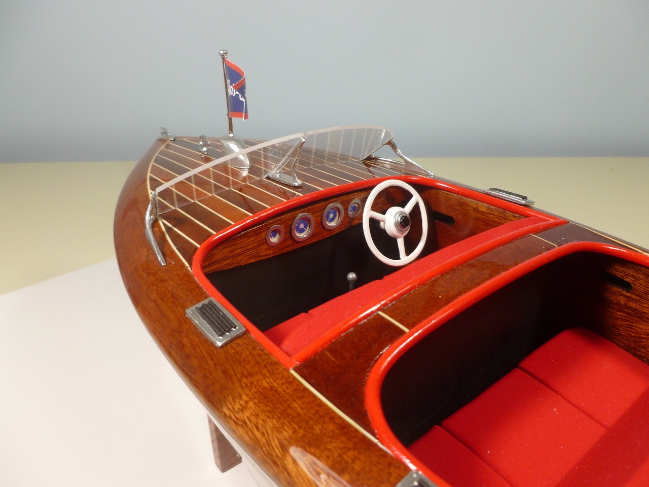
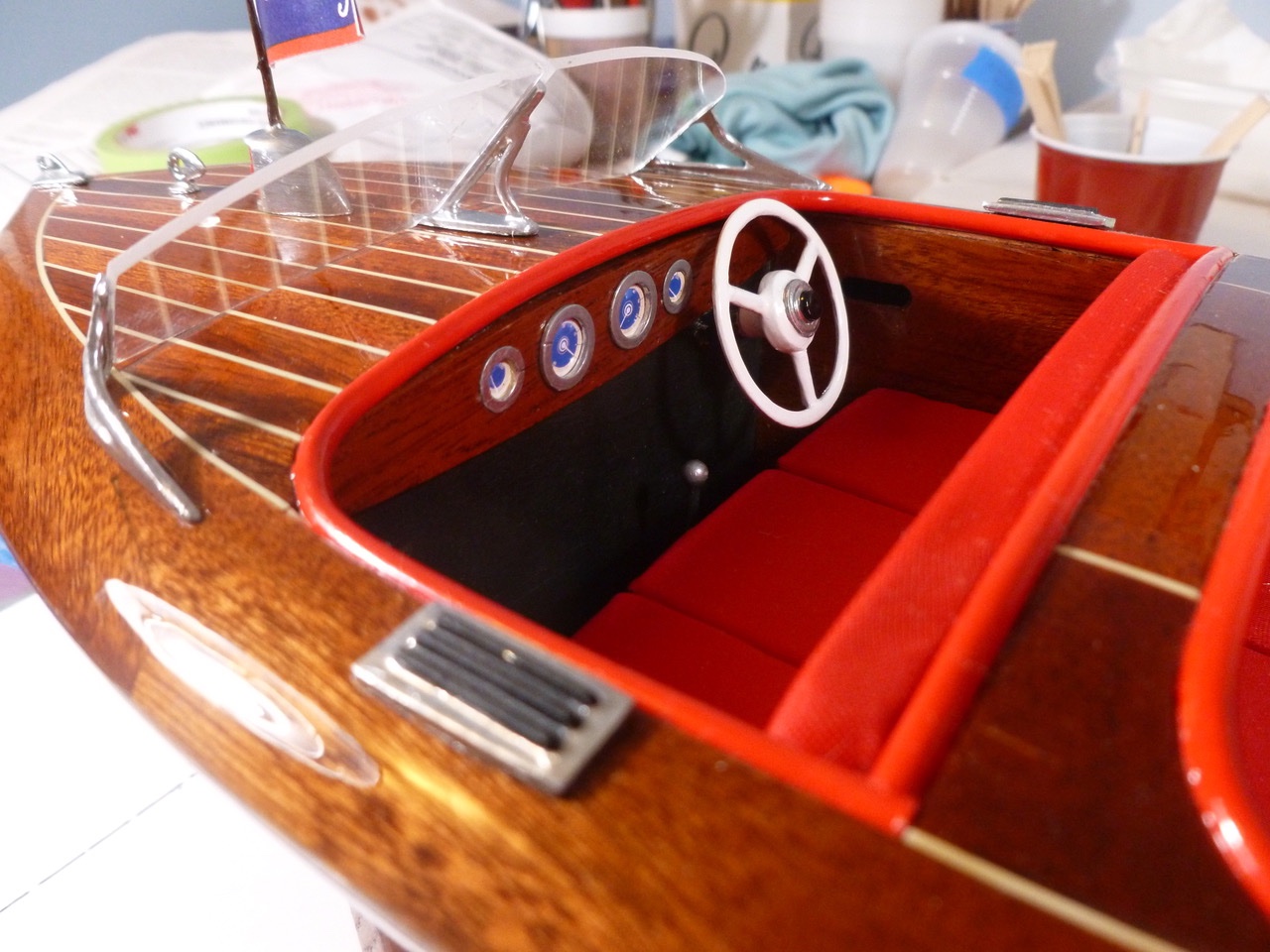
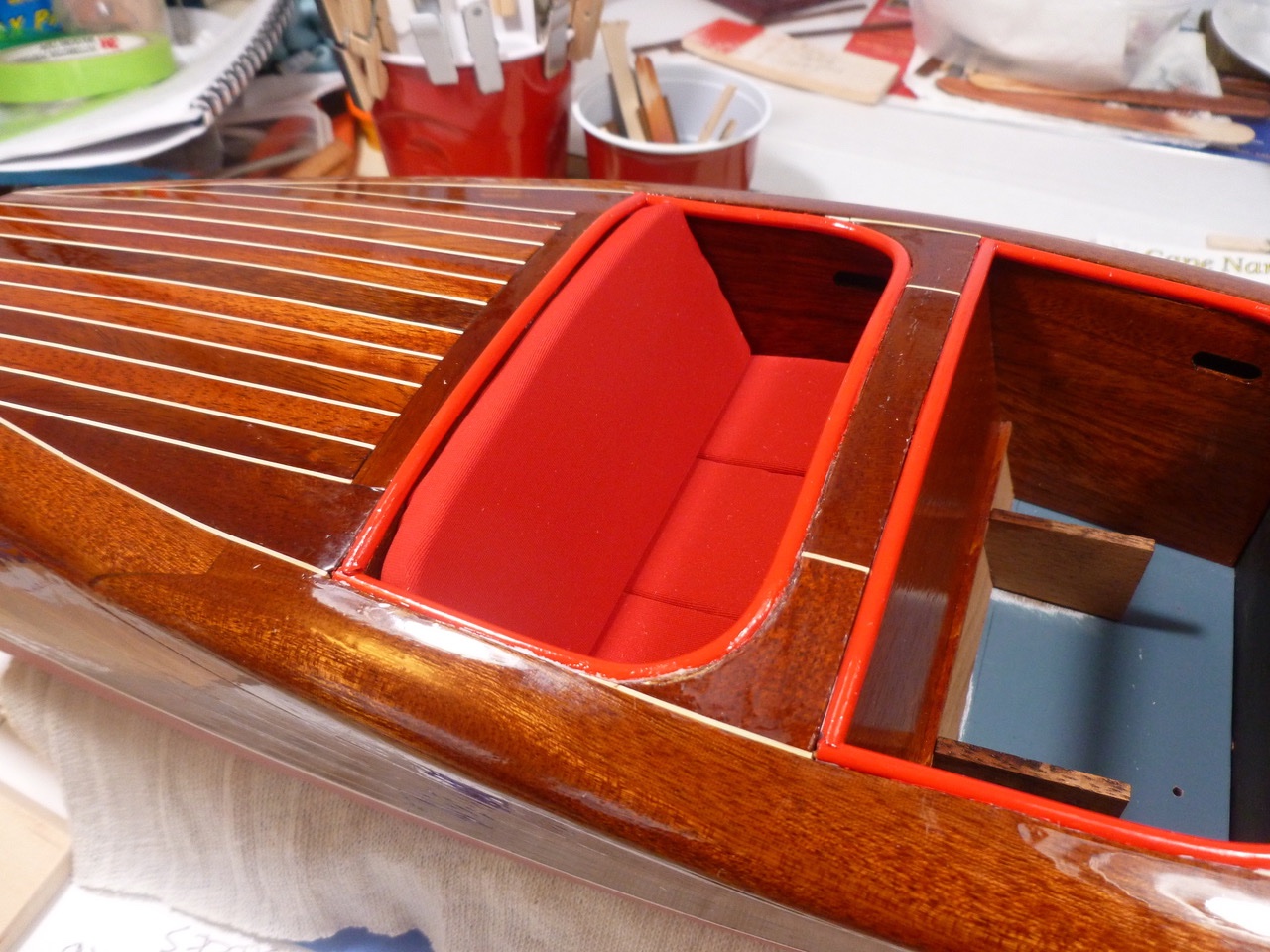
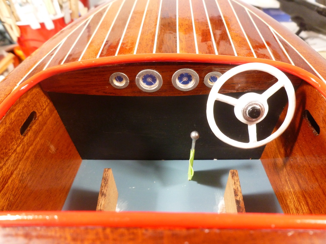
To those who dropped in or gave likes, thank you for your interest and support. To those who have hung in there, double thanks. By now I had my fill with masking so I turned my attention to the cockpit. Before starting the seating work the cockpits must be wrapped with a soft plastic tube to mimic a bolster. Since the tube is glued to the edge of decking and the tops of the inner side panels there was a good deal of woodwork trimming, filing and sanding to provide the requisite backing. I was concerned that if I pre-finished the tube the paint would crack when the tube was bent, and a painted tube would be harder to glue. I installed the tube raw and masked (guess I wasn’t completely filled up) around it for painting. The seat cushions started with tracing the kit templates onto basswood and cutting the blanks with a coping saw. Corners and edges were fitted and eased with the trusty Stanley, files and sandpaper. After seeing a three cushion seat bottom in several online barrel back renovations, and after understanding that the seat bottom cushions also served as personal flotation, I sawed them into three parts each, followed with easing of the cut edges. Seems to look like they belong there, even against a one piece seat back. I chose a stretchy fine weave red fabric to mimic the red upholstery I had seen on several full size boats. Yes, I know the real upholstery was leather, but the scale model size leather bits at the local fabric shop were too small and the wrong color, and the real leather was too thick with too large a grain. Aleene’s Original Tacky Glue was used to adhere the fabric to the basswood blanks. I applied it to the edges and backs only, to avoid having bleed through on the seat faces. This allowed me to wrap the corners and edges and avoid stitchery. I can sew bears with a machine but I’m not at the level of an upholstery miniaturist. A caution: Even a thin fabric takes up room. I had to trim both seat backs and seat bottoms to provide clearance with the inner cockpit surfaces, in several cases only after removing freshly installed fabric to gain access to the basswood. The floor shifter is a 1/16 inch aluminum tube with a round plastic headed sewing pin glued in the end. To make the round head blend with the tube I dipped the assembly in chrome silver paint and hung it upside down to dry, then repeated the process a few times to get some buildup at the joint. I’ve seen a variety of finishes and styles for the steering wheel, but I liked the simplicity of a white wheel and spokes with a chrome bezel and black button. Another caution: While I drilled the steering wheel shaft on an angle as described in the instructions, I left a little clearance between the shaft and the underside of the instrument panel, to avoid damaging the panel with the drill. This proved problematic when I set the front seat base and upholstered seat bottom cushion. The wheel almost touched the cushion. The fix, such as it was, involved removing the seat bottom fabric, sanding the seat bottom basswood until it cried uncle, and installing new fabric. I gained enough separation so a skinny legged driver might be able to wedge under the wheel. If I had to do it again I might even notch the instrument panel to gain more height for the steering wheel shaft. Fortunately the seat bottom cushion is kind of tucked down and it’s not completely obvious that it’s thinner than the back seat. More templates, more masking tape. The windshield is one of those items where you wish you had more hands. But it laid out reasonably well after sanding a good bevel along the bottom edge and very carefully bending the Britannia metal side brackets. After the test fit the “glass” was put aside while the brackets were painted. Thanks for viewing. Steve
- 40 replies
-
- 8
-
-
- BlueJacket Shipcrafters
- Chris-Craft
- (and 2 more)
-
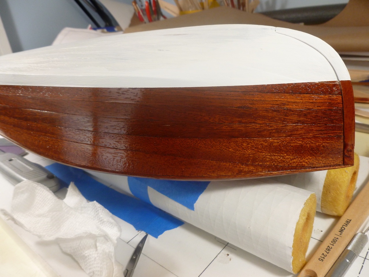
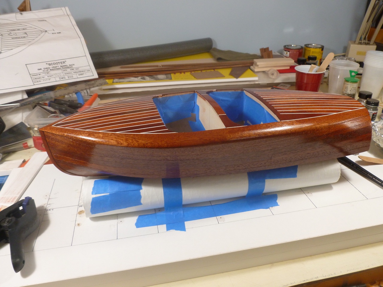
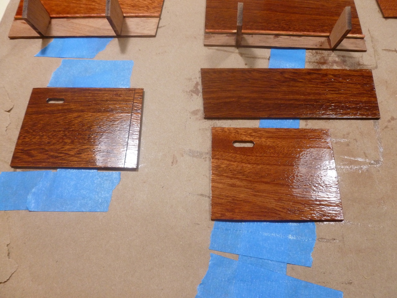
To those who dropped in or gave likes, thank you for your interest and support. Knocklouder, thank you for your kind feedback. The toasting pirates remind me of several visits I have made with grandson in tow, to the Whydah pirate museum in West Yarmouth, Massachusetts. I highly recommend it. Gak1965, thanks to you too for your encouraging comment. I appreciate it. Nic, thanks for the hint. I had previously read it in your great newsletter but managed to not remember it at the right time. Another Bluejacket newsletter tip was most helpful when doing the waterline masking. While laying on more coats I took a few photos to see if the depth of finish would be visible. The samples are below. The reflections are from two Luxo lamps (worklights with adjustable arms) that light my work area. The barrel back sides near the stern were the most challenging to get smoothly curved, starting with the stringers and working up through the basswood inner planks and into the mahogany. Still have a few small ripples that impact the clarity of reflections, but I’ve worked the wood and finishes about as far as I dare without breaking through any of it. Thanks for viewing. Steve
- 40 replies
-
- 5
-
-
- BlueJacket Shipcrafters
- Chris-Craft
- (and 2 more)
-
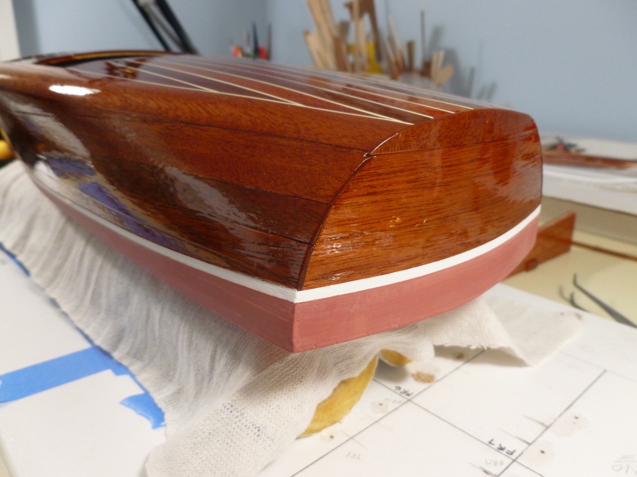
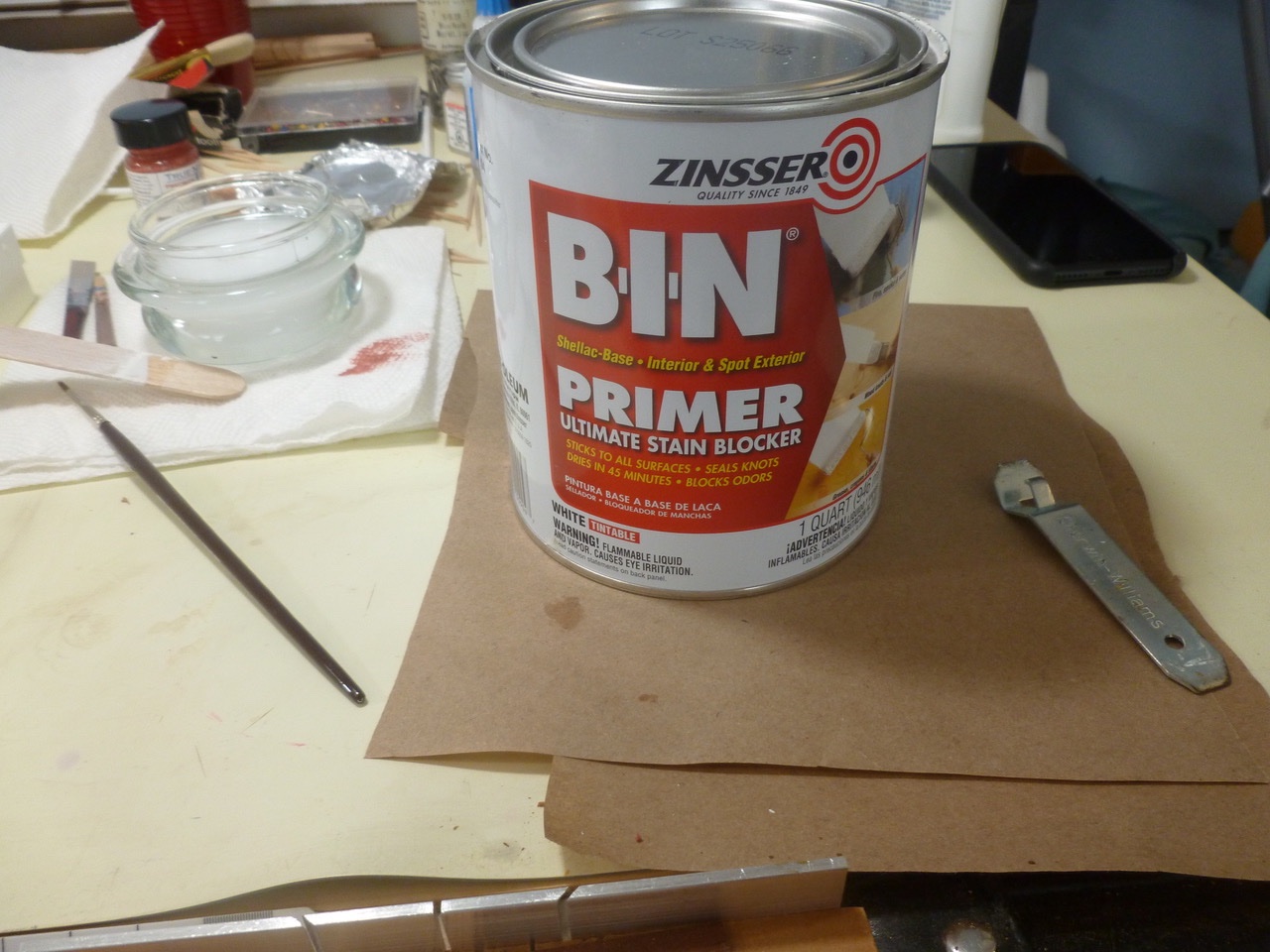
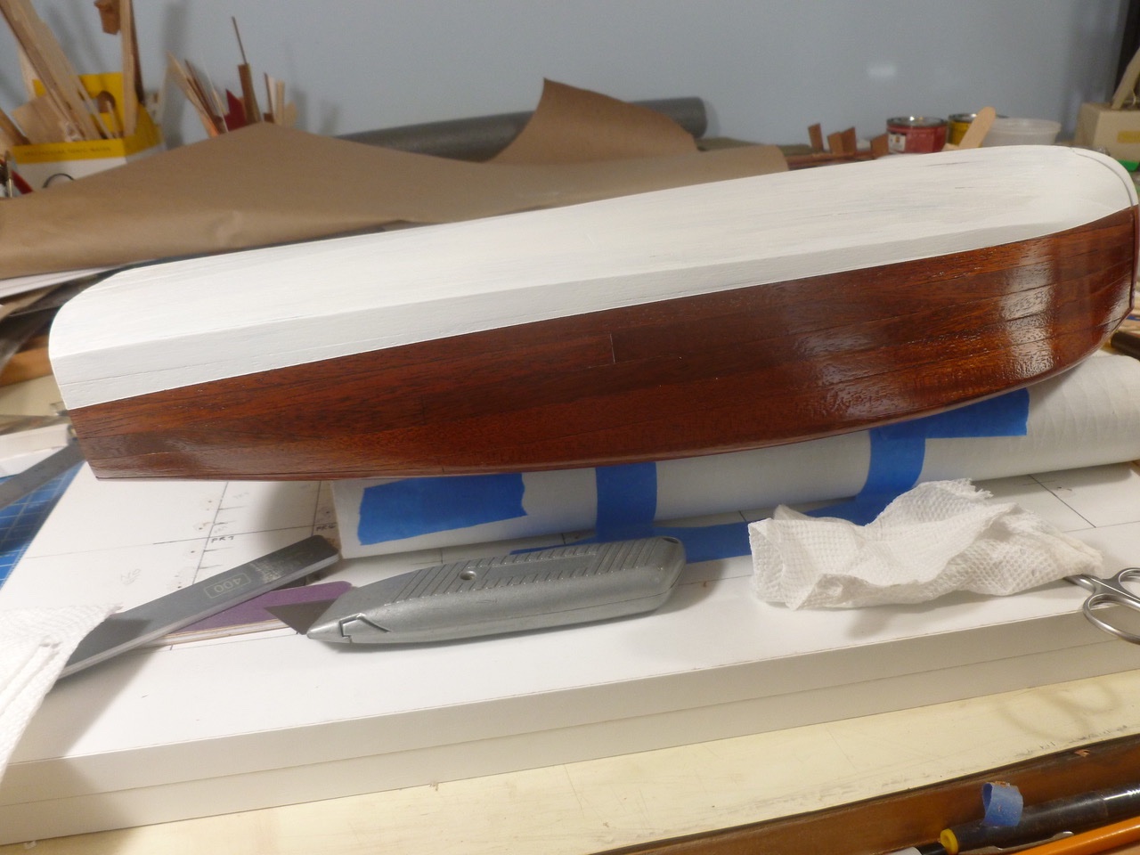
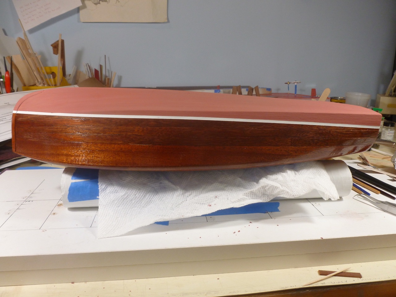
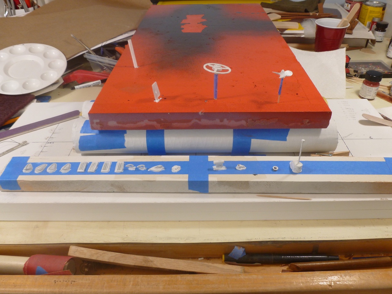
To those who dropped in or gave likes, thank you for your interest and support. Paul, thank you for your kind comments and enthusiasm. I really appreciate it. After the base urethane coats were thoroughly dry I turned attention to the bottom and the Britannia (non-lead) metal parts. BIN has been my go to primer for years, way before ship building. It’s a bit thin and more than a bit stinky but it covers well, hides all sorts of stains, dries very fast, and leaves a nice surface for top coats of just about anything. Just make sure to ventilate well if you decide to roll an entire bedroom with it to seal up a layer of pink paint (ask me how I know). A piece of rigid foam insulation makes a pierce-friendly base for any items on a stick or projected pin. Upside down painters tape on a stick takes the rest and is easily turned to give access to all sides. The bottom planks showed a bit through the primer and paint. In my mind that’s okay and more in keeping with my goal of no filler and an honest representation of a planked hull. This is the first time I tried a separate waterline and it was interesting to see the number of re-maskings required along the same layout line, exacerbated when I needed to go back and add more coats to the bottom and sides. I burnished all the tape edges with the end of a basswood plank sanded to eliminate sharp edges. After a few very small snots were excised with an X-acto the waterline stood clean and reasonably sharp. It may have a slight curve but it seems to mostly go away when the boat is upright. Time for more masking to allow finishing the clear coats. Thanks for viewing. Steve
- 40 replies
-
- 6
-
-
- BlueJacket Shipcrafters
- Chris-Craft
- (and 2 more)
-
To those who dropped in or gave likes, thank you for your interest and support. Todd, I appreciate your kind words. Thank you. I like “re-surfacing” since it more accurately represents what I did. While watching the clear dry I knocked together a simple oak base, finished with the same stain and spar urethane as the boat. The oak takes the stain color slightly different, making a little contrast to the mahogany. As the coats built up, the boat took on a pleasing appearance. The instructions called for a base of four coats before turning attention to the hull bottom paint. Thanks for viewing. Steve
- 40 replies
-
- 6
-
-
- BlueJacket Shipcrafters
- Chris-Craft
- (and 2 more)
-
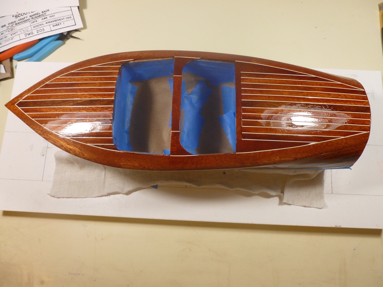
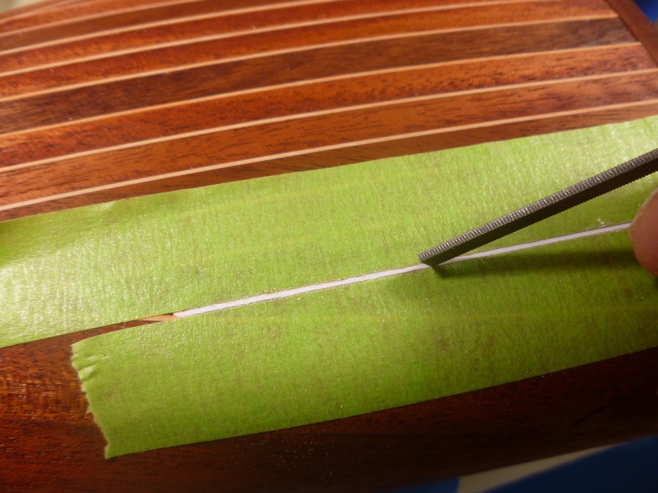
To those who dropped in or gave likes, thank you for your interest and support. Online videos of Chris Craft restorations have been an inspiration during the build. While ruminating on the stained caulk I found two episodes that showed essentially the same approach to caulking deck joints. In both cases each side of an open joint was masked with painter’s tape to protect the mahogany, before installing and cleaning up the caulk. Well, if it worked full size why couldn’t a similar approach work here? The obvious problem is getting something narrow enough to scrape the caulk without damaging the planks. Luckily fate was with me. The narrow edge of a small flat file just happened to fit within the caulk line. A few careful strokes and the stain color was gone, leaving shiny white smiling at me. Fire up patience, grab the tape and away we go. The caulk restoration went much quicker than I expected. The experience masking the B-26 cockpit canopy proved invaluable. In fairly short order (okay it was hours over a couple of days) the caulk lines returned to their original splendor and final sanding could resume. With the caulk catastrophe behind me the first spar urethane clear coat was applied, promptly yielding a few sags so I could learn finish restoration too. Thanks for viewing. Steve
- 40 replies
-
- 9
-
-
-
- BlueJacket Shipcrafters
- Chris-Craft
- (and 2 more)
-
Hi Jack, Good to hear from you. Thanks for joining the build and for your likes. When we took the flight we gave the pilot a tip, more to say thanks in advance than with any expectation. Total safety briefing and equipment consisted of a warning not to stand near the propeller before boarding, and a single lap belt covering the two of us. The flight was wonderful and the low sides of the front cockpit allowed spectacular views. Everything was smooth and level but when we turned back from the river the pilot took us on a steep dive, followed by a steep climb and a whoop-de-do over the top. Positive and negative G's all in about 40 seconds. Bug-eyed but had a great time. Highly recommend it. Steve
-
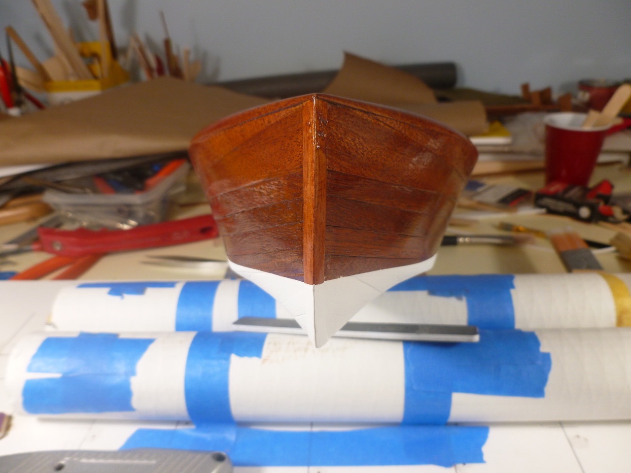
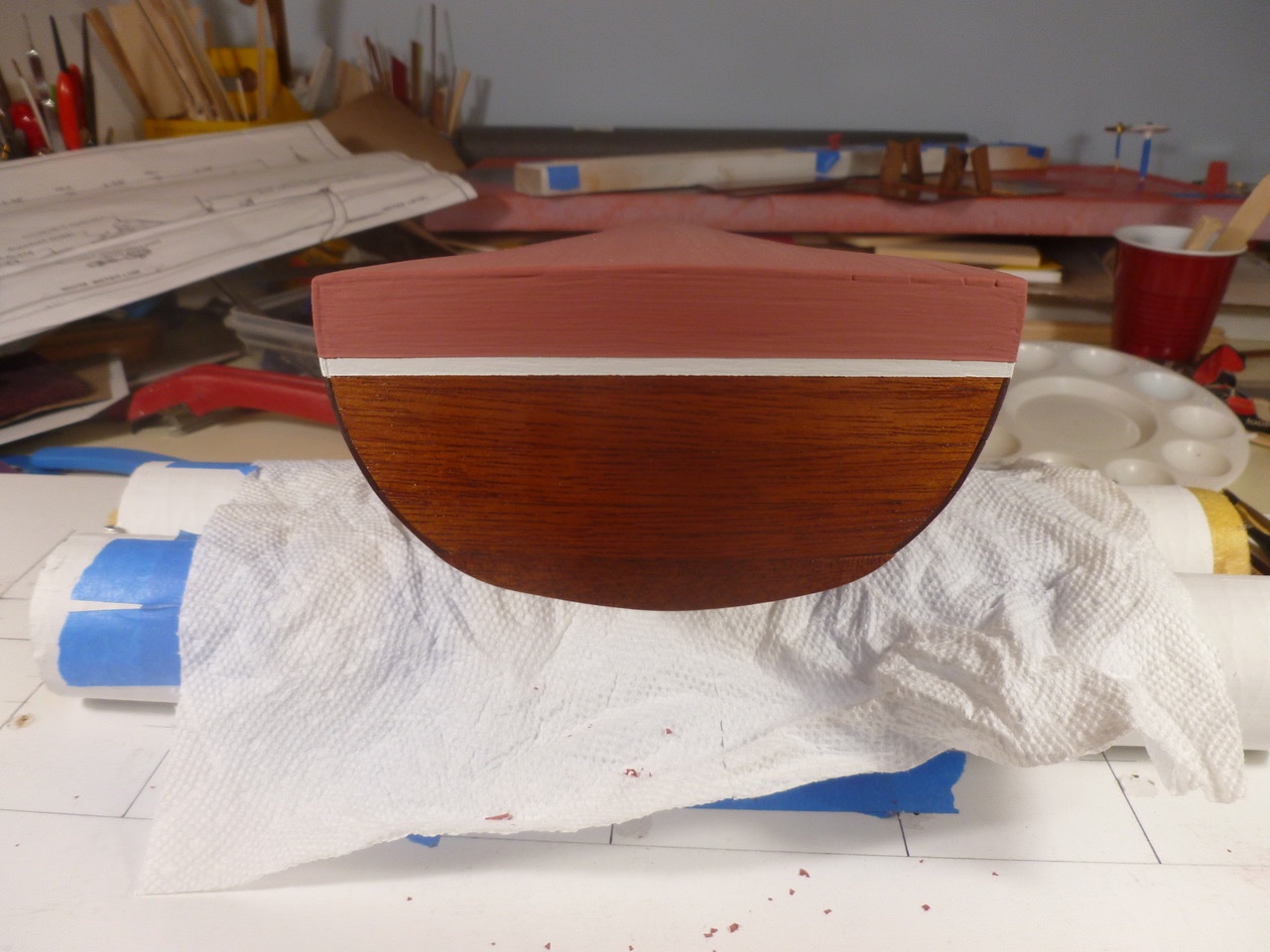
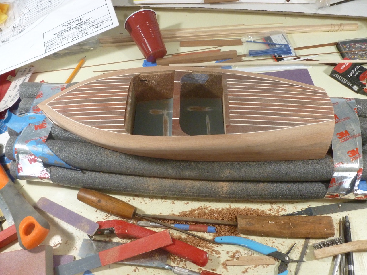
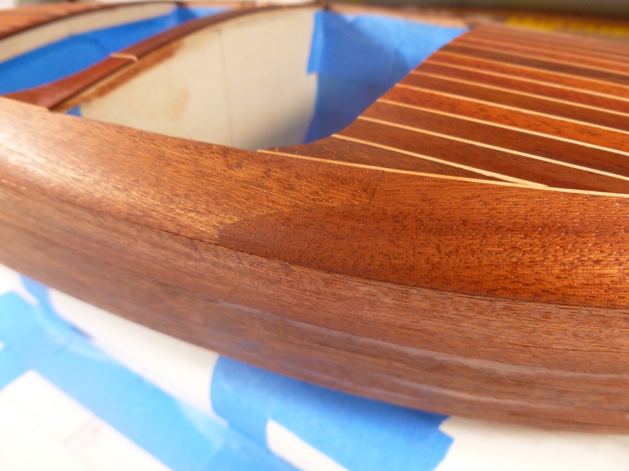
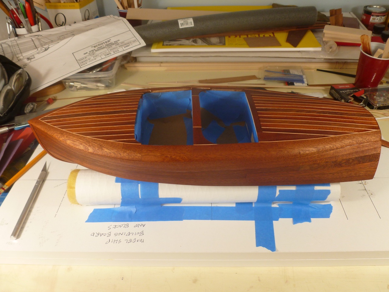
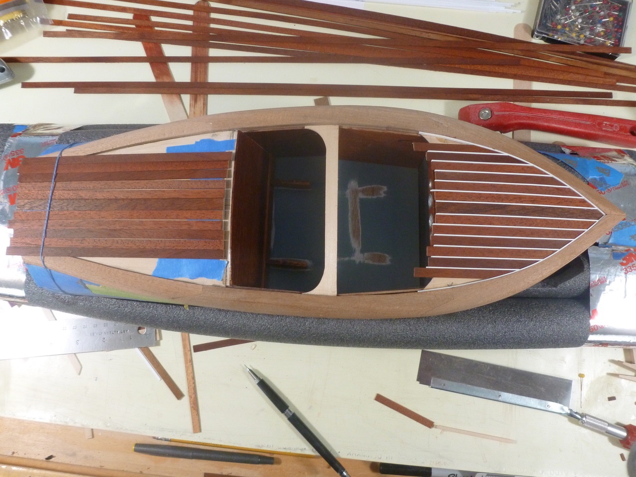
To those who dropped in or gave likes, thank you for your interest and support. Prowler901, thanks for the Wow! Shaping the hull included creating a progressive roll along the length of the sheer; blending side and hull bottom planking at the chine approaching the bow, blending the false stem into the hull, establishing a smooth line for the decking around the cockpit, and sanding down the “caulk” lines to be flush with the deck planks. Tools included two paint scrapers (the wider one was most useful since the curved blade reduced digging in at the edges); old and new coarse and fine files, an old Stanley block plane (amazing how good those old plane irons are); a new Stanley mini-plane (not much use except in very small areas for taking off very little material), and of course stiff and flexible backed sandpaper ranging from 80 to 400 grit. Finally the time had come for installing the last transom plank. I suppose it is arguable that this should be the whiskey plank but the plank shown earlier is my story and I’m sticking to it. It was a challenge getting the plank in place. I had let the covering board blocks run long before I realized they needed to be flush with the inner transom, to allow the final transom plank to cover the ends of the covering boards. It took awhile to sand down the end grain of the covering boards without damaging the edge of the mahogany plank below. Unfortunately this view highlights the sanding and scraping marks in the deck, created while trimming the styrene caulk lines. Stupid of me to think I could take those lines down without damaging the pre-stained deck planks. Now I had to include the deck area as part of the hull staining project. All that effort to keep the caulk white and now it would be back to orange-red. Bummer. Well, at least the joints were pretty tight and the staining was uniform. I’m particularly proud of the zig zag joints and the way the covering boards flow smoothly from deck to hull sides. Those caulk lines need some hard thinking. Thanks for viewing. Steve
- 40 replies
-
- 6
-
-
- BlueJacket Shipcrafters
- Chris-Craft
- (and 2 more)
-
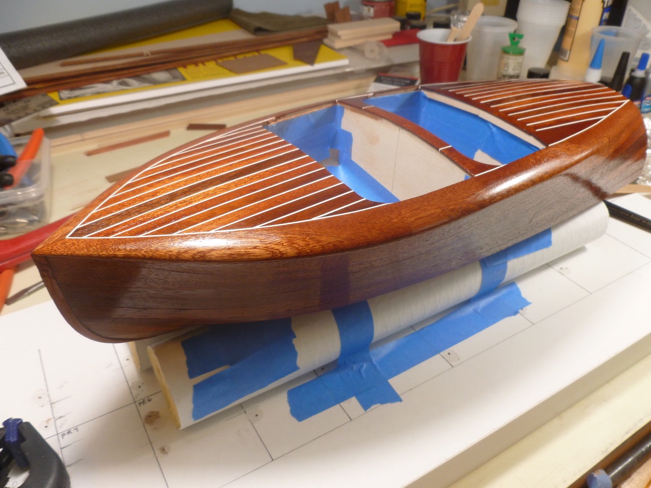
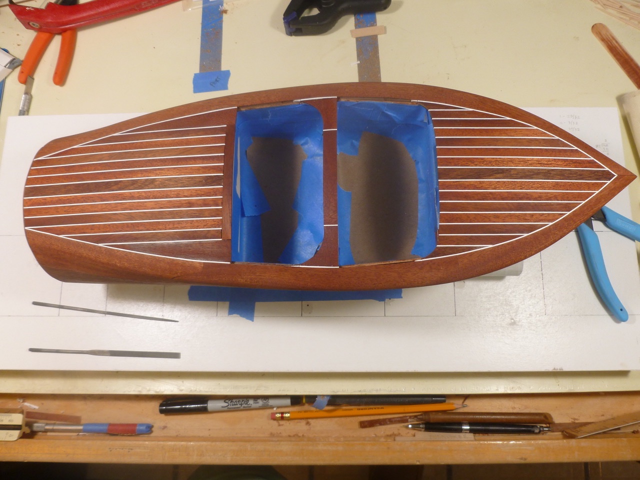
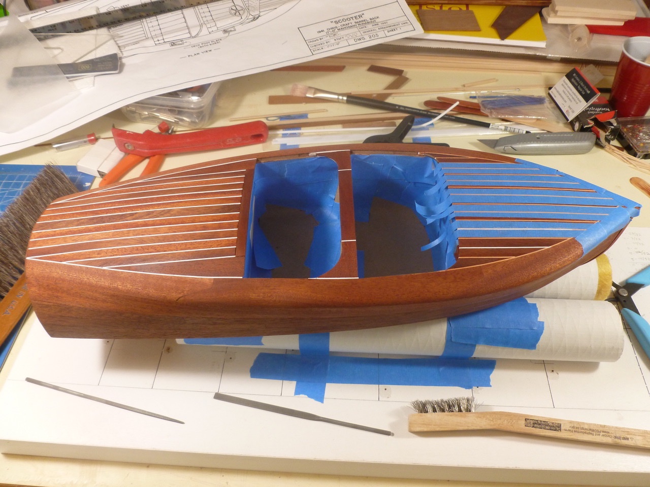
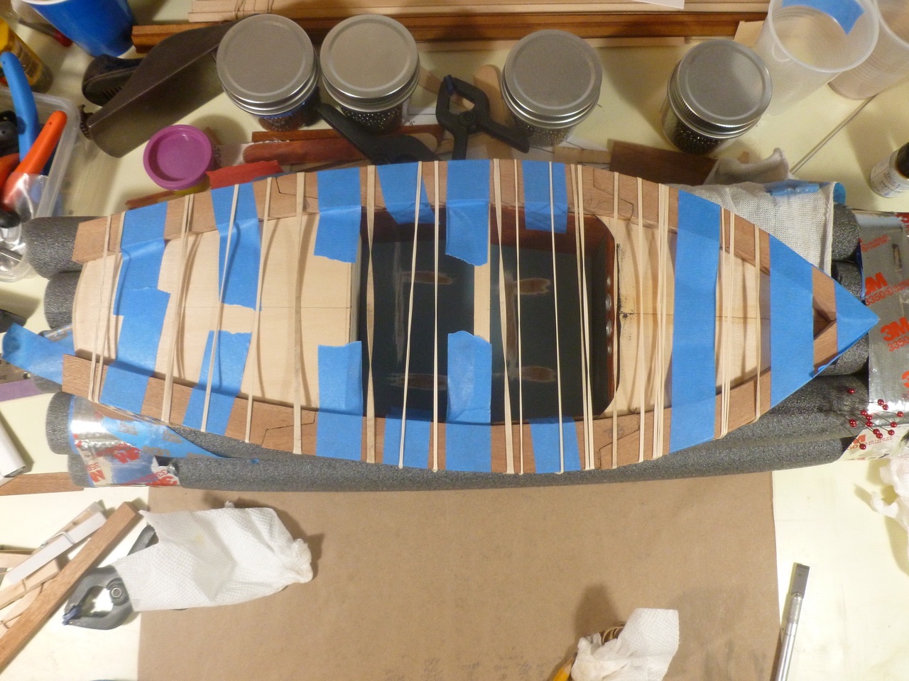
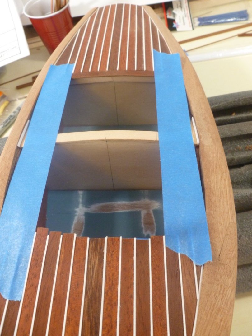
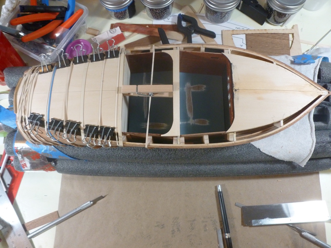
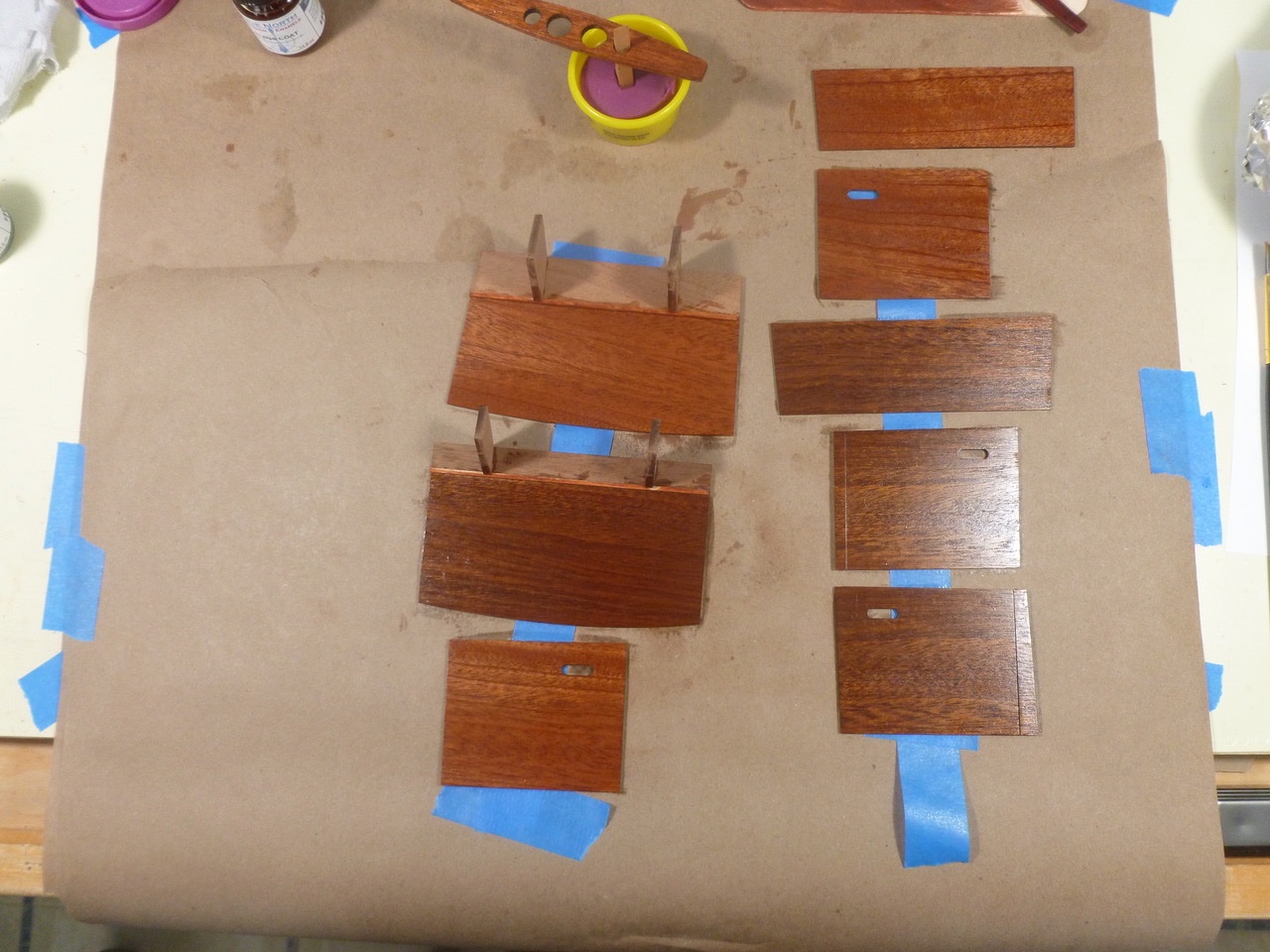
To those who dropped in or gave likes, thank you for your interest and support. gsdpic, thanks for hanging in there. I truly appreciate it. The first of many, many covering board test fits. Each adjustment required removal and replacement of a board, with attendant rubber bands and tape to snug things up. The boards curve with the deck cross slope, the deck sheer, the side plank sheer and the fore and aft tapers. Every adjustment in one dimension impacts every other dimension, and every adjustment requires tweaking of the zig zag joints between each covering board. Oh boy, this fits, now that doesn’t; and why doesn’t this side look like the other, and OMG none of it sits tight to the side plank sheer, and that joint was closed but now it’s open…. The stuff that dreams are made of. I thought about trying a Dremel for some of it, but with no room for filler and a one speed Dremel I stuck with the slower but gentler option of all hand work. The progress photo gives an idea of the amount of covering board material that must be removed. Eventually the covering boards decided to work together and were glued in place with outboard edges and height above deck all left proud for later shaping after the deck planks are installed. The deck planks are started. I pre-stained the planks with the hope that the “caulk” strips, which are styrene slightly taller than the planks, would remain a nice bright white. The pre-staining brought out the color differences among the mahogany strips, which I took advantage of by creating a symmetrical pattern of dark and light strips. Both planks and strips required progressively sharper bevels where they intersected the caulk strips at the covering boards. I mocked up the aft planks and numbered them to ensure the color pattern would match the fore deck. Once the fore and aft deck planks were installed I ran a piece of tape at each caulk joint that would carry through the cockpit divider area. This space calls for one caulk joint each side with a transverse plank between, and shaped pieces of mahogany on each end. Thanks for viewing. Steve
- 40 replies
-
- 7
-
-
-
- BlueJacket Shipcrafters
- Chris-Craft
- (and 2 more)
-
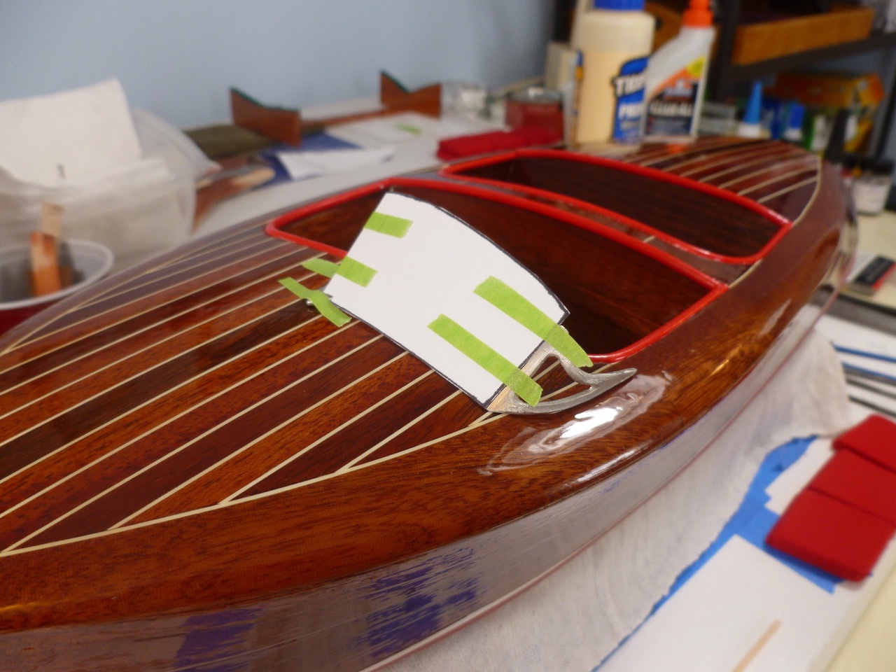
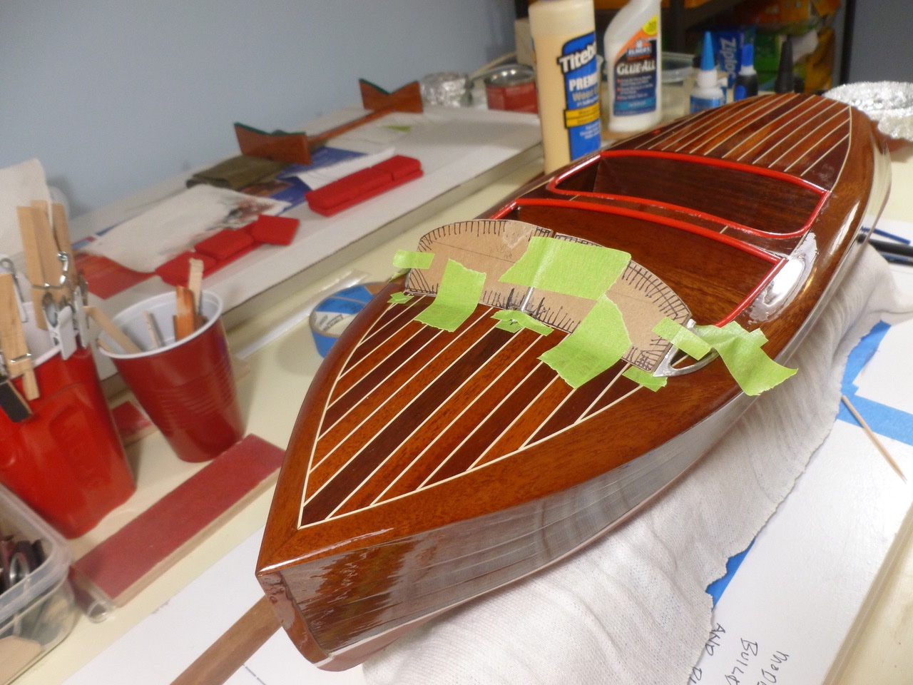
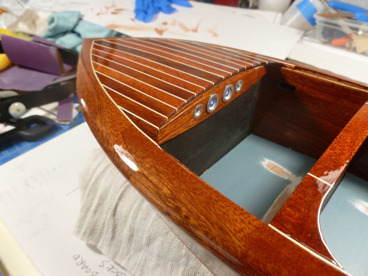
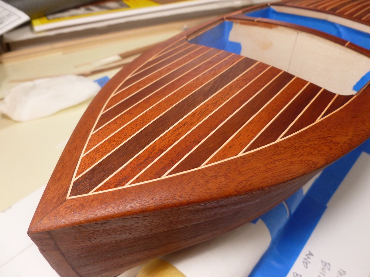
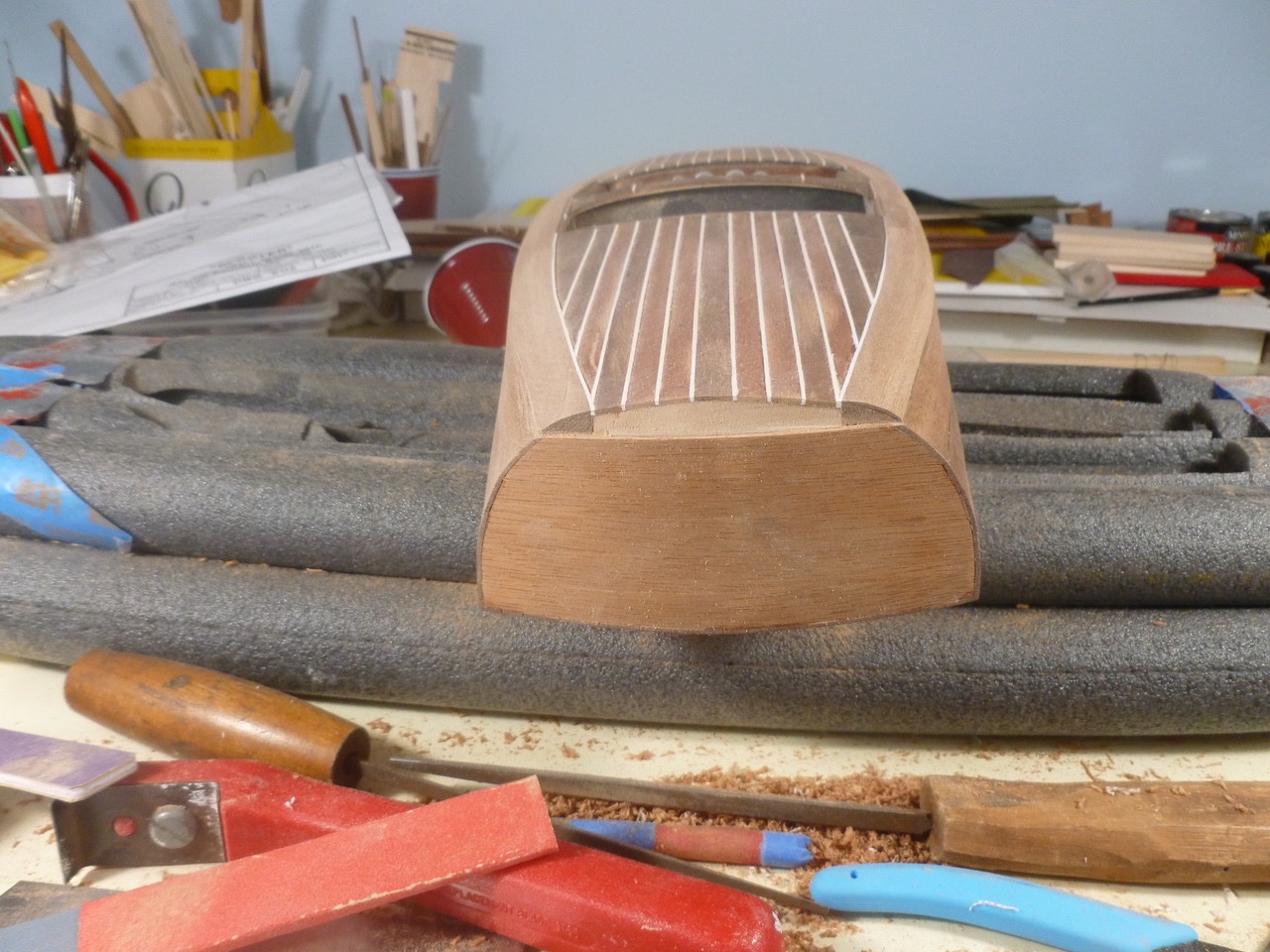
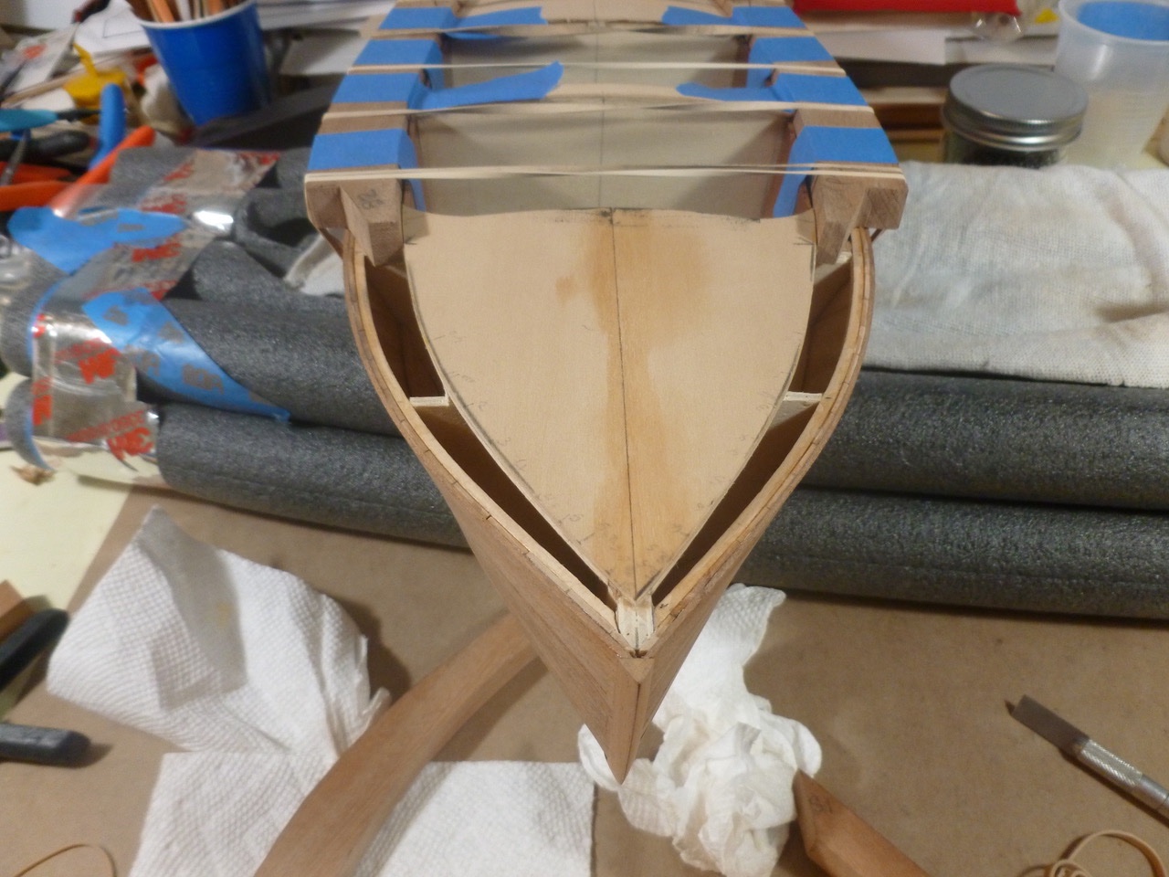
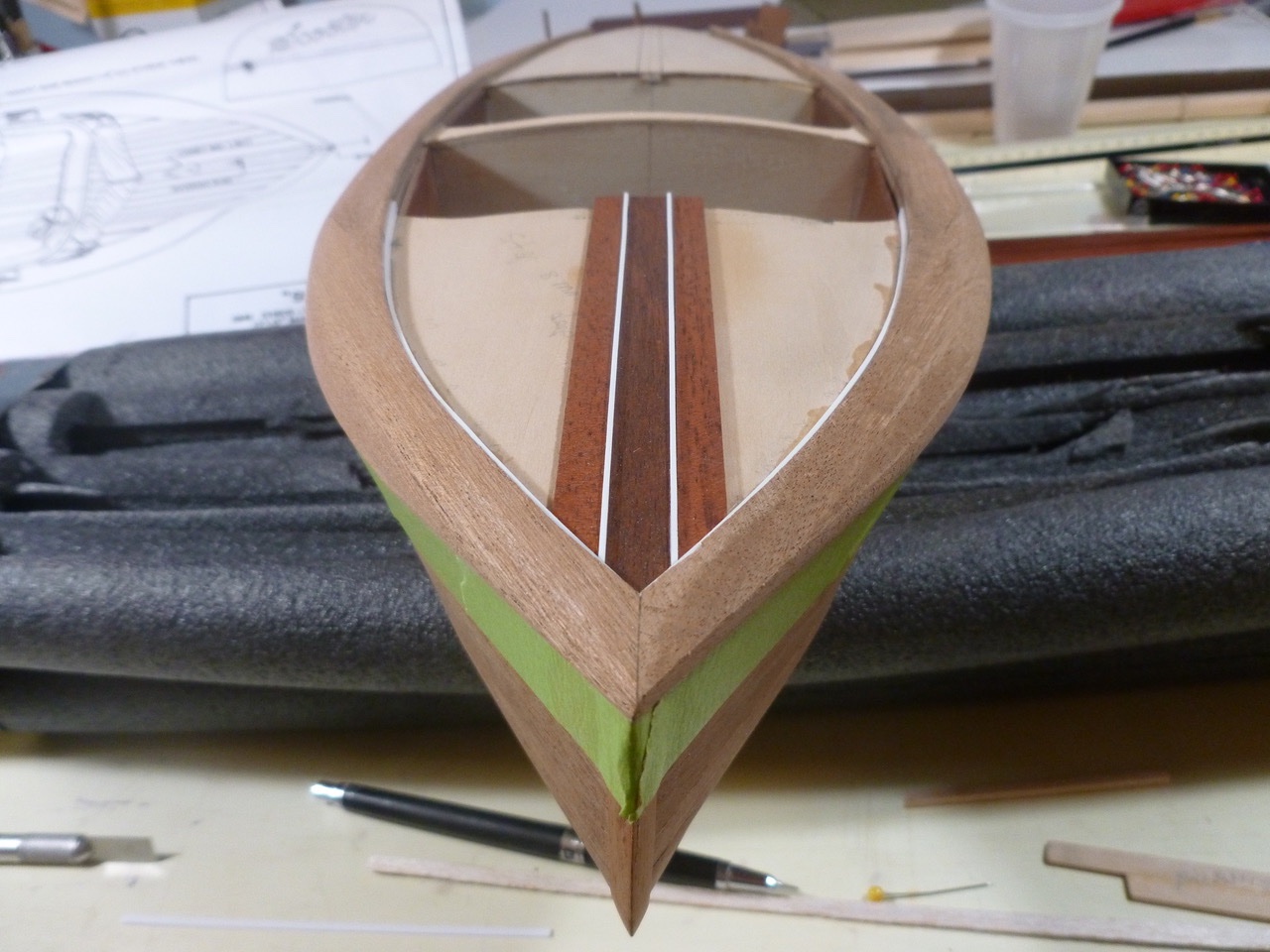
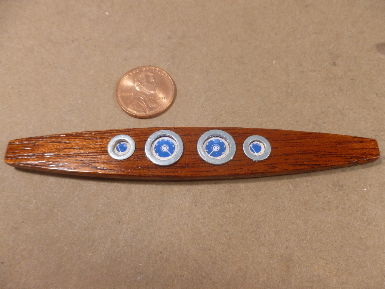
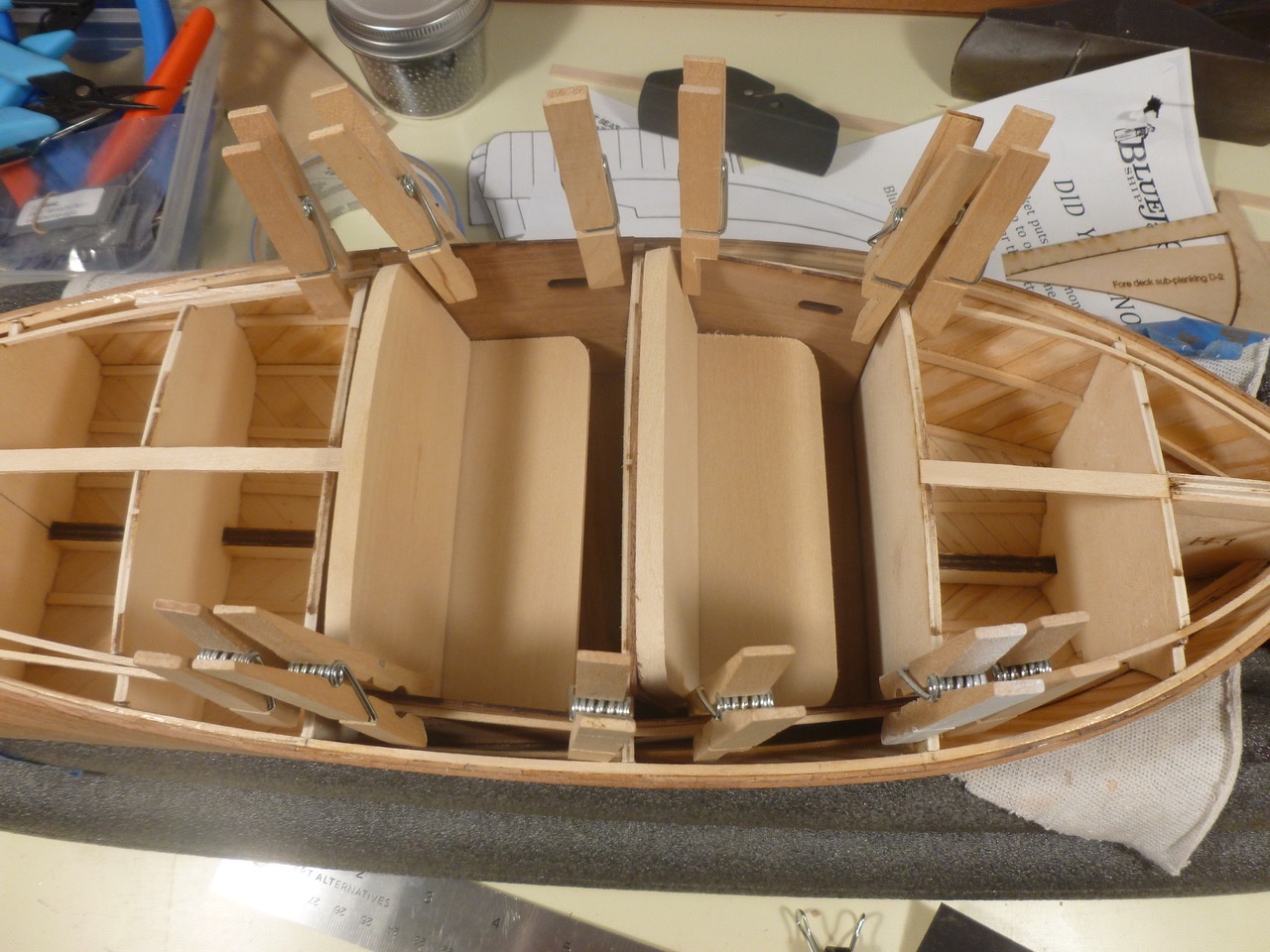
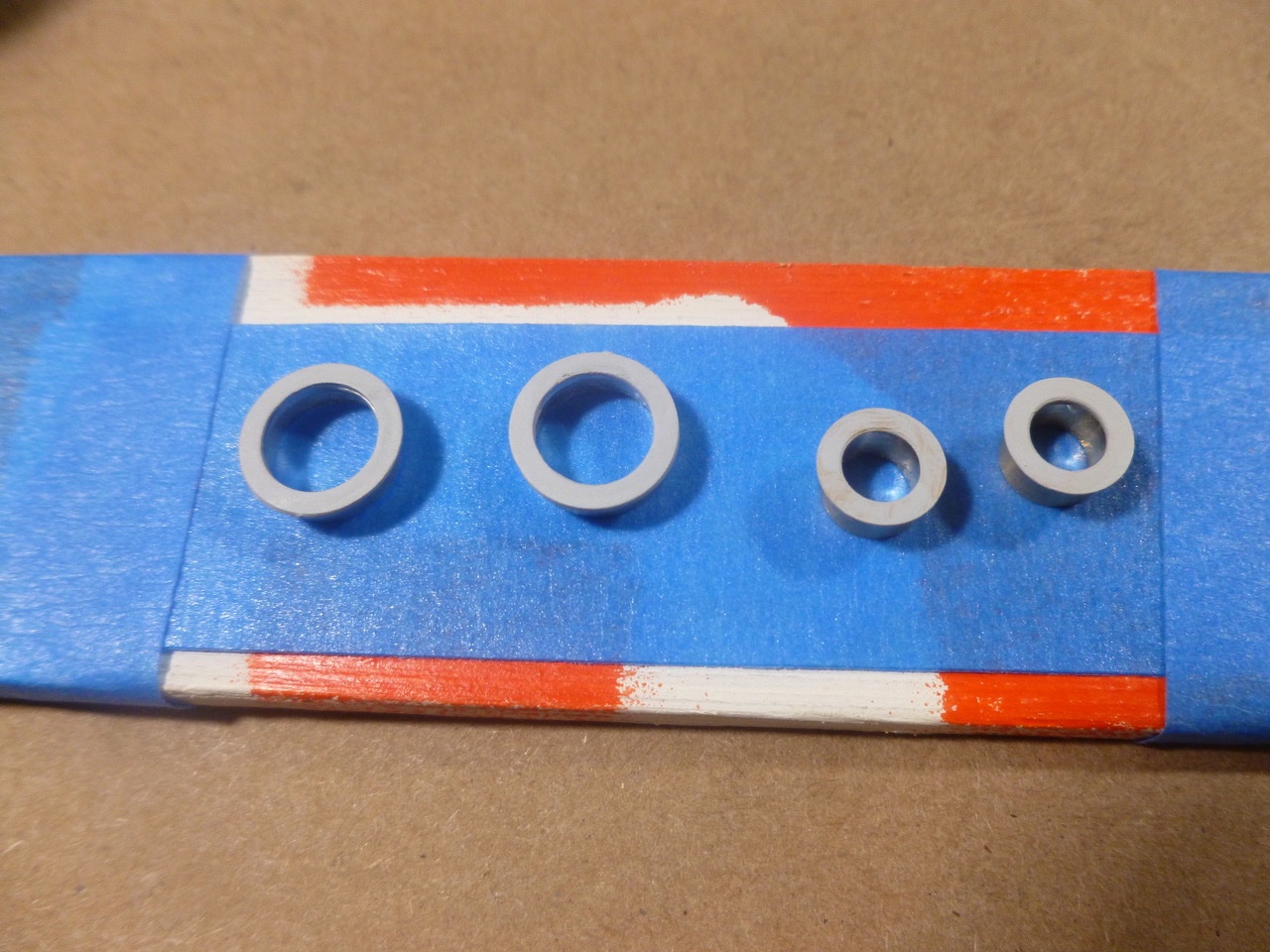
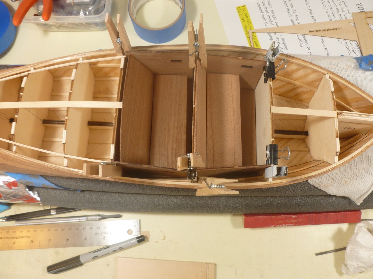
To those who dropped in or gave likes, thank you for your interest and support. Once the instrument panel was sanded and finished along with the cockpit panels, the instrument faces were fitted to the trim bezels (now painted chrome silver and the bezels were installed in the panel. Sounds simple, but as old Rose said in Titanic, “The reality was somewhat different”, or words to that effect. The trim bezels extend through most of the instrument panel similar to a porthole window. The blue faces were a screen shot scaled down to fit and printed on copier paper. Thanks go to the Antique Boat Center of Cleveland for their advertisement of a similar barrel back. A balsa disc was cut for each bezel and a blue face was glued to each disc. The disc was mounted into the bezel, leaving a little reveal at the forward edge so the instrument looked recessed. The reveal depth was set with a scrap of balsa during press fit of the instrument disc into the bezel. The completed panel was glued to the front bulkhead in the forward cockpit after painting the bulkhead flat black. The forward sub deck bends in two directions, necessitating multiple rubber bands and clamps during gluing. The bow photo shows how thin the covering board will be at the forward end. The aft sub deck and center sub deck between cockpits were installed after being fitted to the structure and covering templates. The curves on the center and forward sub decks were adjusted from their laser cut profiles to match the as-built conditions so they would align with the interior panels. The covering board templates were trimmed for close fits to the sub decks. The outboard edges were left wide for now. This was an iterative process involving the cockpit panels, the sub decks and the transom. A little off here, a little adjustment there, and a little reconsideration along the way. Chasing millimeters. Once all parties were in agreement the covering board templates were traced onto the mahogany block and cut out with my new handheld jigsaw. Crude compared to a table mounted unit but got the job done. And after planing, scraping and sanding, the covering boards will bear little resemblance to the rough blocks anyway. Thanks for viewing. Steve
- 40 replies
-
- 5
-
-
- BlueJacket Shipcrafters
- Chris-Craft
- (and 2 more)
-
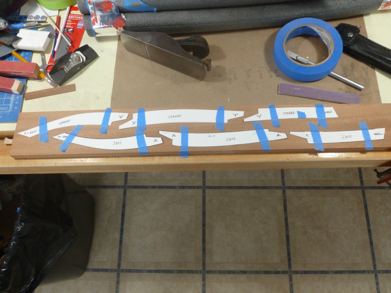
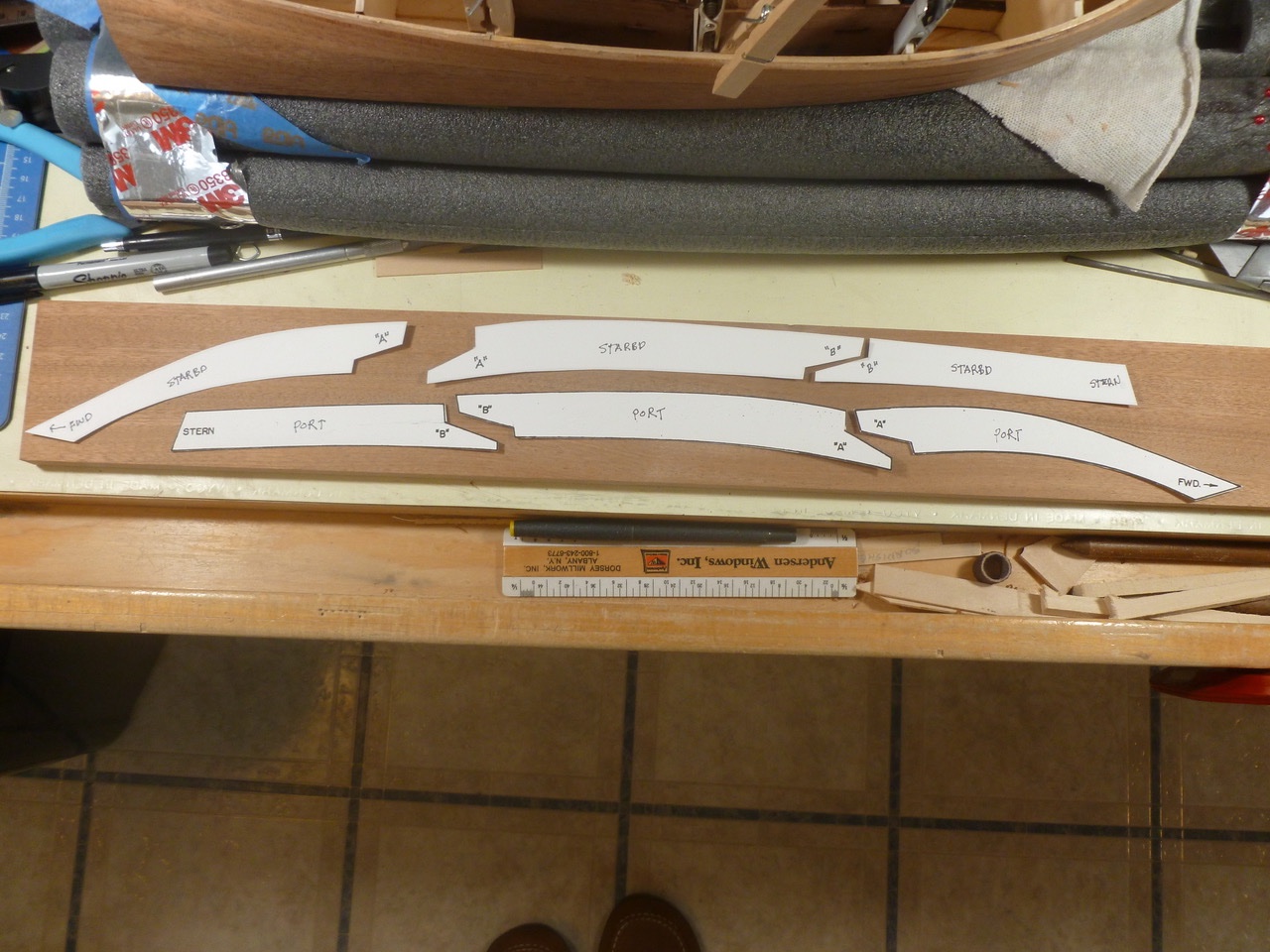
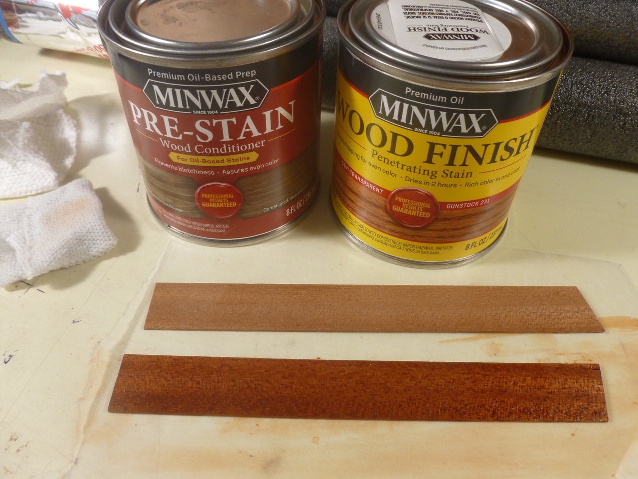
To those who dropped in or gave likes, thank you for your interest and support. I thought it would be easier to finish the cockpit panels before installing them, and since the bulk of the finish would be hidden from view it was an opportunity to learn the ins and outs of stain and varnish. What a topic. There are many blog, forum and other online opinions regarding the right color, base material, brand, application method, prep and final finishing; both in and out of the ship modeling community. What is gospel for one is heresy for others. It reminded me of a comment I heard from a retired sailor working on the USS Slater in Albany, NY when I told him I was researching the correct gray color for the Zebulon B. Vance. He said, “Just pick one you like; they used whatever they had when painting during the war, sometimes two or more different colors on one ship.” Maybe I should have asked his opinion on foam or bristle brushes (what kind of bristles my son?), rough or fine nap rollers, rattle cans or an airbrush. On one forum a fellow said he was pleased with Minwax oil based color Gunstock 231, since he felt it gave a reddish tint that approximated early post war Chris Crafts. It was available locally so I happily jumped off the finish merry-go-round and picked up small cans of stain and the recommended pre-stain conditioner. I also grabbed Minwax Helmsman spar urethane for consistency between stain and finish. The Helmsman was described as clear gloss but it actually has a slight amber tone. More on that later. As I worked the interior panels I realized that stain color, especially a semi-transparent stain, was only one part of the finished appearance. The color of the mahogany had a significant impact as the photo shows. The photo also shows where I grafted in small extensions to the two aft side panels (bottom right in the photo) after a test fit showed the panels to be a bit short in length. In the end, stain agonizing was minimized when the interior panels came out well. While trying to capture the shininess of the spar urethane I realized more sanding will be needed, both in the wood and between coats. I also started to see the importance of multiple coats in creating depth. The perimeter basswood stringers survived multiple fitting attempts and gave a reasonably symmetrical base for the upcoming port and starboard covering boards. There is considerable taper to the forward deck, not only in width but also in height which means mucho carving and sanding of the covering boards, from a starting thickness of about a half inch to the finished thickness of an eighth inch or less at the bow. Paper templates are included in the kit for the covering boards, three to each side. I traced them on Bristol board for stiffness. I learned quickly that the templates are only a guide and a starting point. The covering boards start as one lump of mahogany. Sharpen up the tools. Thanks for viewing. Steve
- 40 replies
-
- 5
-
-
- BlueJacket Shipcrafters
- Chris-Craft
- (and 2 more)
-
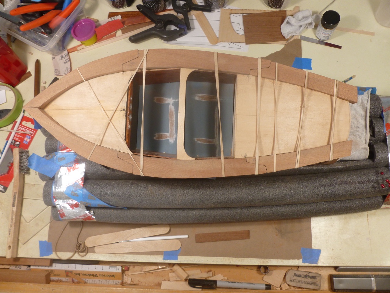
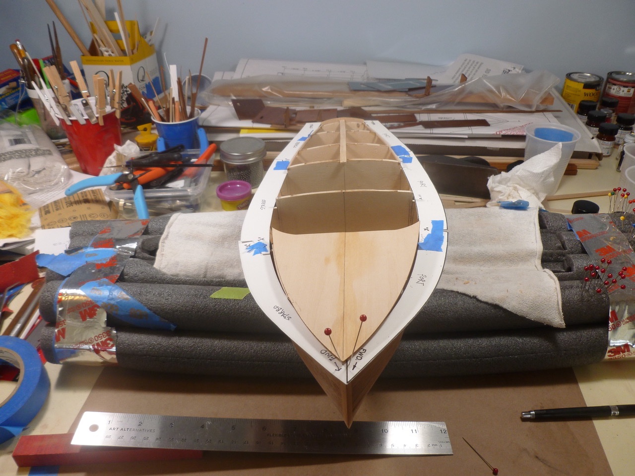
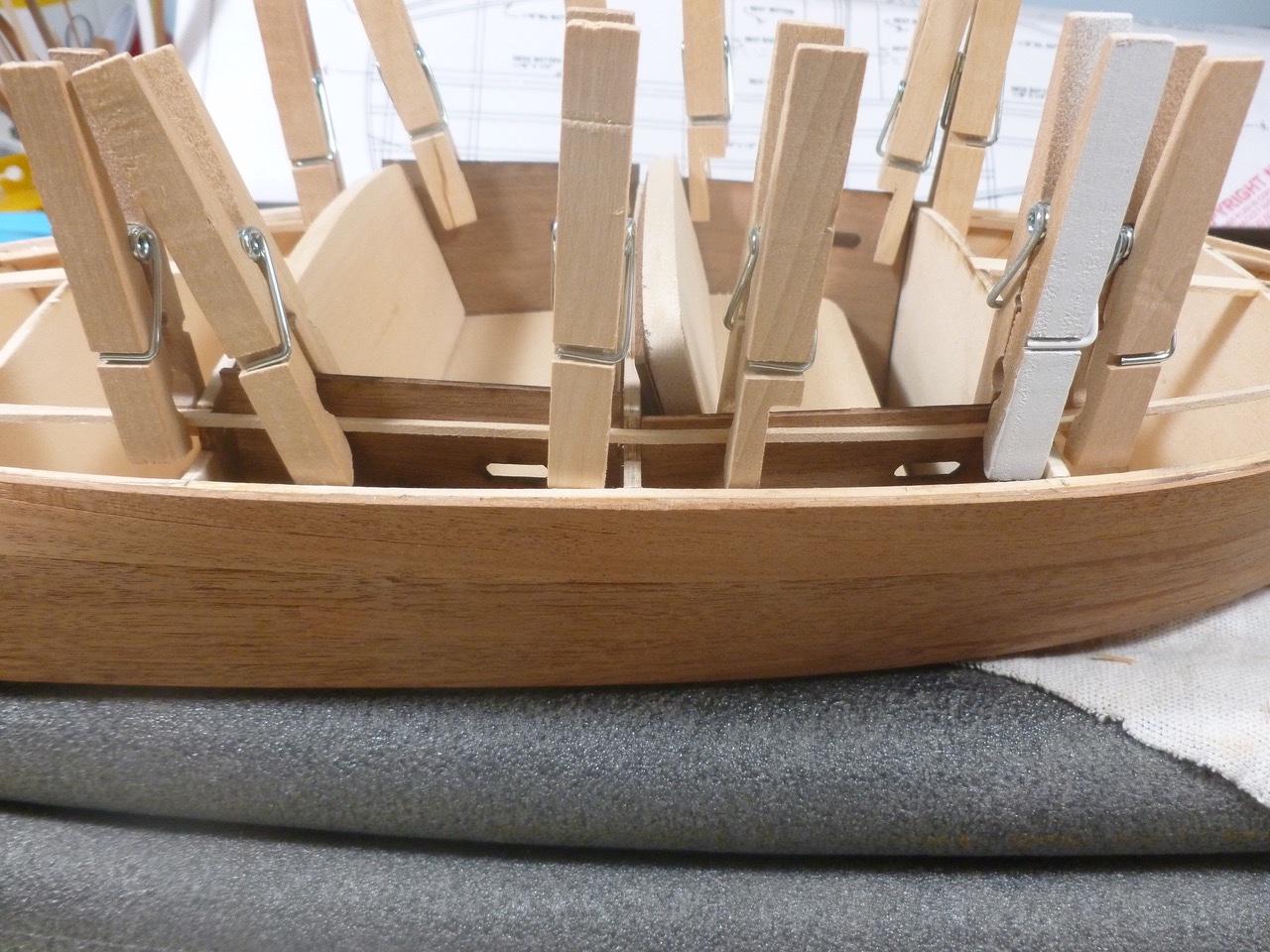
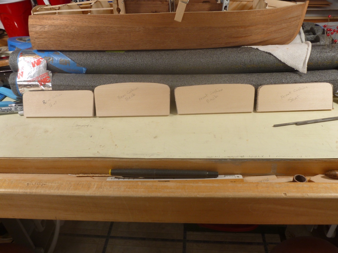
To those who dropped in or gave likes, thank you for your interest and support. Roger, thank you for your kind comments. The Bluejacket mahogany was first rate. I was leery of working with mahogany since my experience on a previous model showed it to be stiff and brittle. I think the combination of Bluejacket’s wood, steam bending and using templates to minimize overbending all contributed to the final product. Once the hull and side planking was installed, attention turned to the deck and cockpit. This area requires stringers and center sub planks to establish the profile for the covering boards and to provide a landing for the sub deck. It also requires accurate perimeters for the fore and aft cockpits since the deck planking terminates without benefit of any covering trim apart from the cockpit perimeter tube cushion. The cockpits contain floor (ceiling?) panels, inner side panels and support panels for the seat cushions. The side panels must be blocked to the hull side structure to allow a fair line for the covering boards. The hull bulkheads serve as the forward and aft cockpit area enclosures. The instructions show a choice of two seating arrangements. One is for the kit-supplied cloth seat covering to be applied directly to the seat support panels. The other is to paint the kit-supplied basswood seat back and cushion blocks, after carving to fit. Since the kit cloth was green and I fancied a red interior I chose to shape the basswood and decide how to finish it later. Once the top of the port and starboard side planking was planed and sanded to meet the sheer stringers, and after the floor panels were placed, the inner sides were fitted to meet the deck stringers. Clothes pins came in very handy to hold loose pieces during test fitup. The side panels required tapered blocking at the leading and trailing edges to ensure good contact with the panels and the adjacent hull side structure. Much sanding and planing of support panels, cushions and side panels was needed for a tight fit, especially since I was trying to accommodate the several millimeters of bulkhead layout inaccuracy mentioned earlier in the build log. While taking a break from the cockpit adventure I primed the instrument bezels. Thanks for viewing. Steve
- 40 replies
-
- 6
-
-
- BlueJacket Shipcrafters
- Chris-Craft
- (and 2 more)