ESF
-
Posts
381 -
Joined
-
Last visited
Content Type
Profiles
Forums
Gallery
Events
Everything posted by ESF
-
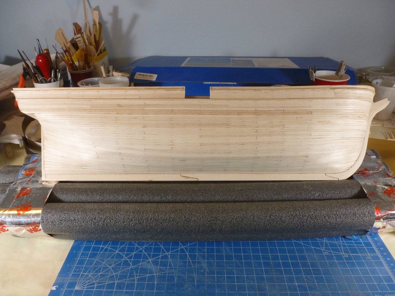
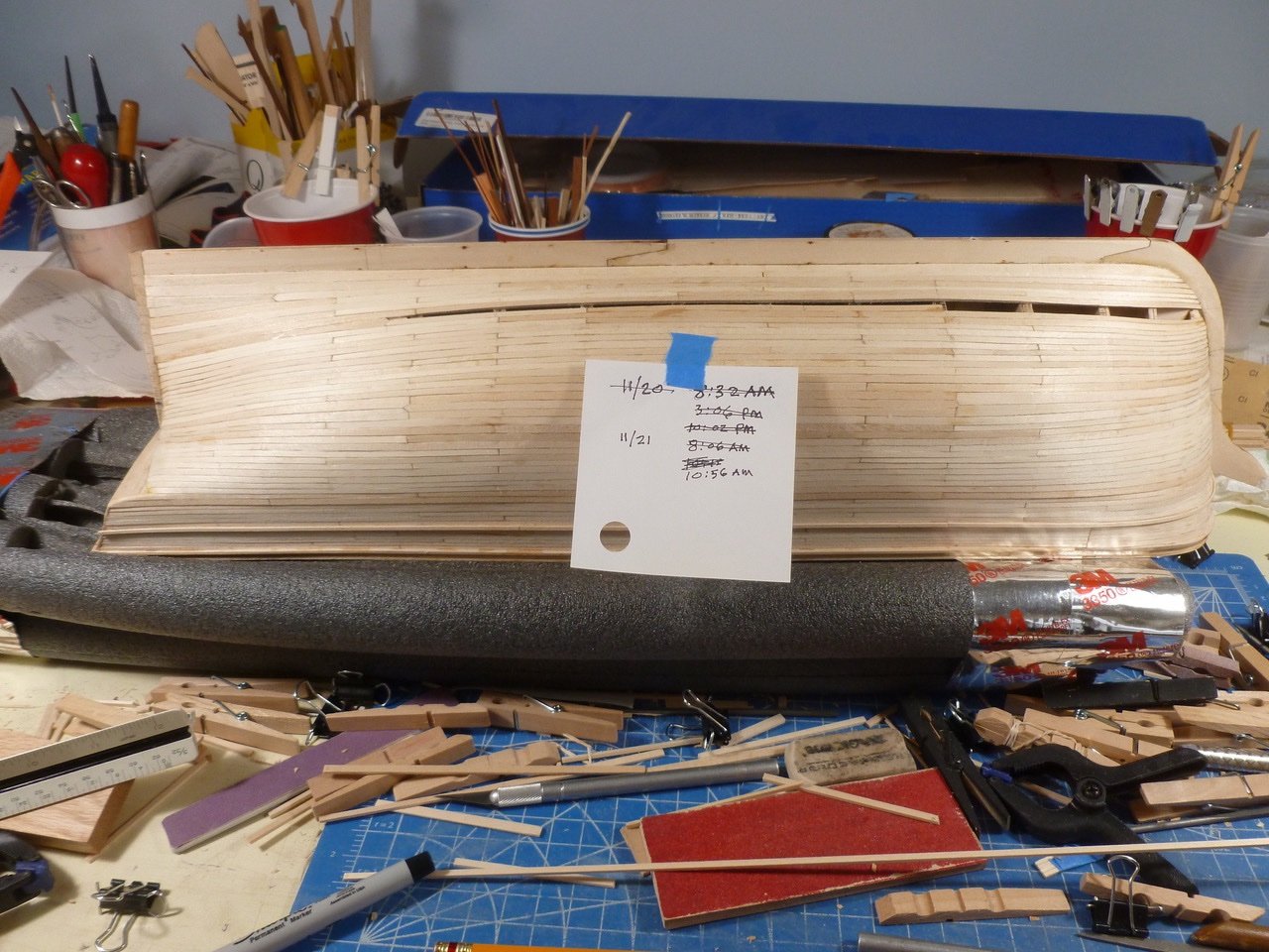
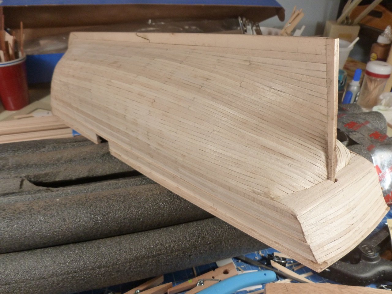
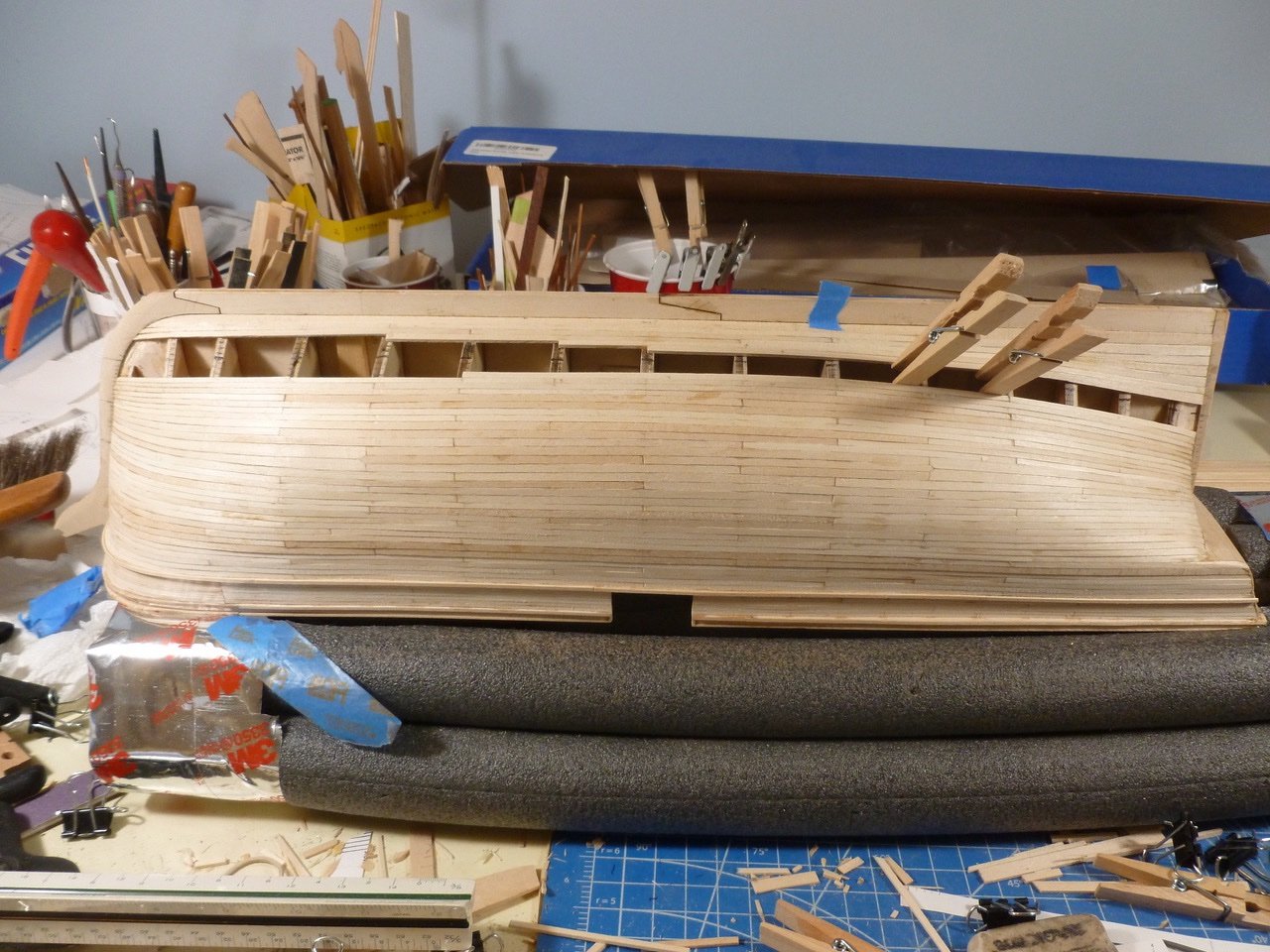
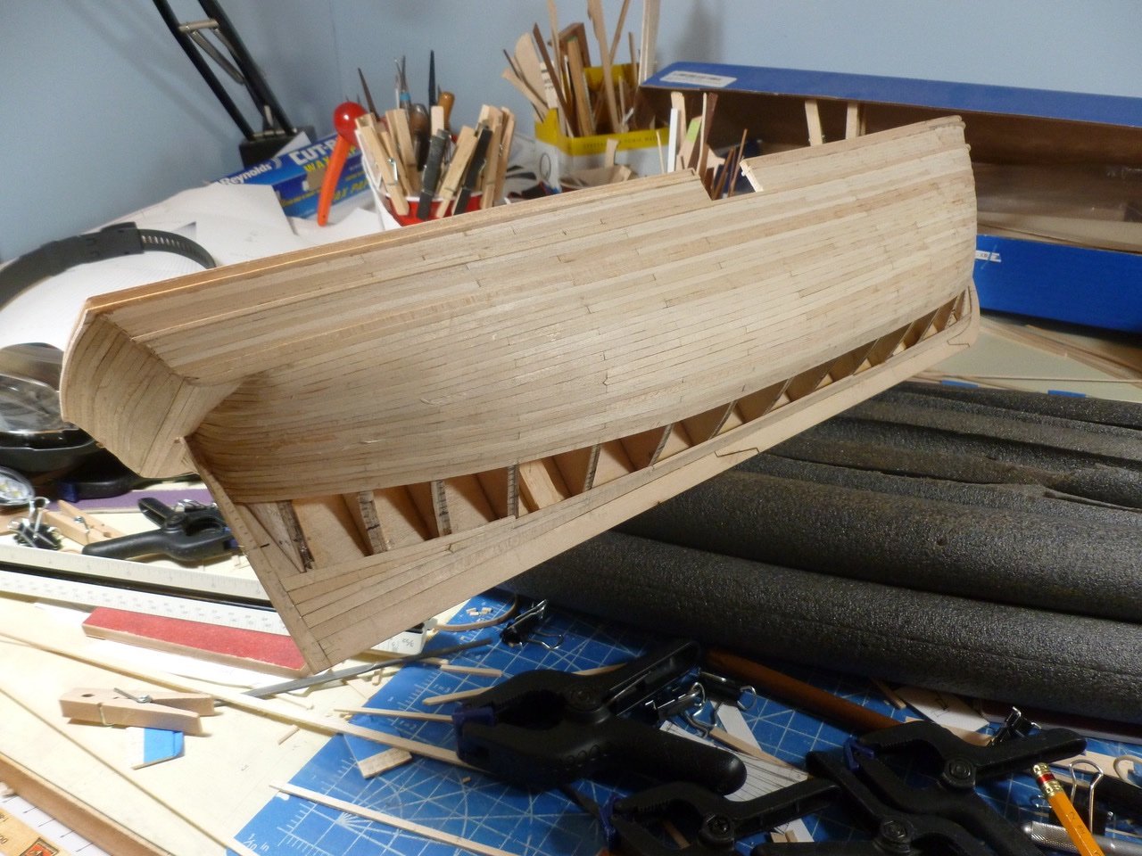
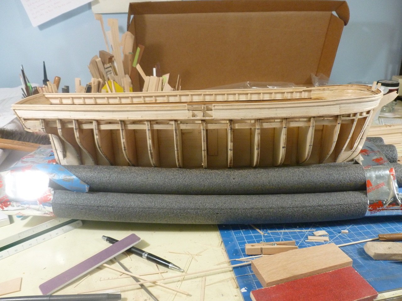
 To those who dropped in or gave likes, thank you for your interest and support. Okay, one clarification. My office was on the third floor and the little sign at the entrance said “Come up two flights to get the job done right”. Memory gets fuzzy. Hull sanded The hull sanding is substantially complete. I’m thinking the hull may be good enough to paint rather than plate. Any opinions? Pics below. Thanks for viewing. Steve
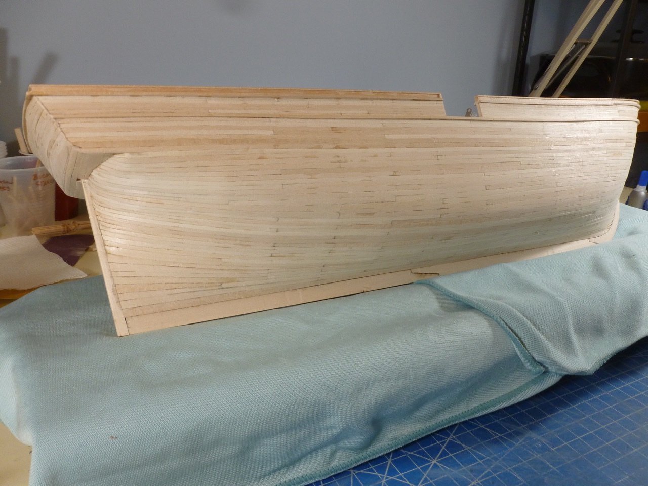
-
I was counting the front steps 😀
-
Skipping to the end, I just placed an order for the 3/32" width strips with Model Shipways. If I'm going to build it I want to build it correctly. Reminds me of my first architectural office, on the top floor of a three story walkup. I put a little sign at the bottom of the stairs with my name on it and the phrase "Come up three flights to get the job done right". Back to the build. Steve
-
Happy Thanksgiving to all. To those who found time to drop in or gave likes at the same time you were eating, thank you for your interest and support. A new challenge(?) The drawings and instructions are quite specific about the number of strakes within each hull planking band (A-10, B-10, C-10, D-8). When the counts were transferred to tick strips there were many instances where a 3/32" plank width was the logical choice, as compared to 1/8" which was the other choice. Now that the hull planking is finished I found that I am way short in 3/32" strips (scale 6" plank width) for the deck planking, but there appear to be sufficient 1/8" strips (scale 8" plank width) to cover the deck. The instructions call for 3/32". The deck plank photos in the Charles W. Morgan picture history book from Mystic, when compared to shoes on the crew, seem to imply a 6" width. I would like to make efficient use of the provided lumber but I don't want to make a muck of the deck appearance, assuming a 1/32" oversize on the planks is indeed a muck. Has anyone run into this, either with a Morgan build or another project? Thank you Steve
-
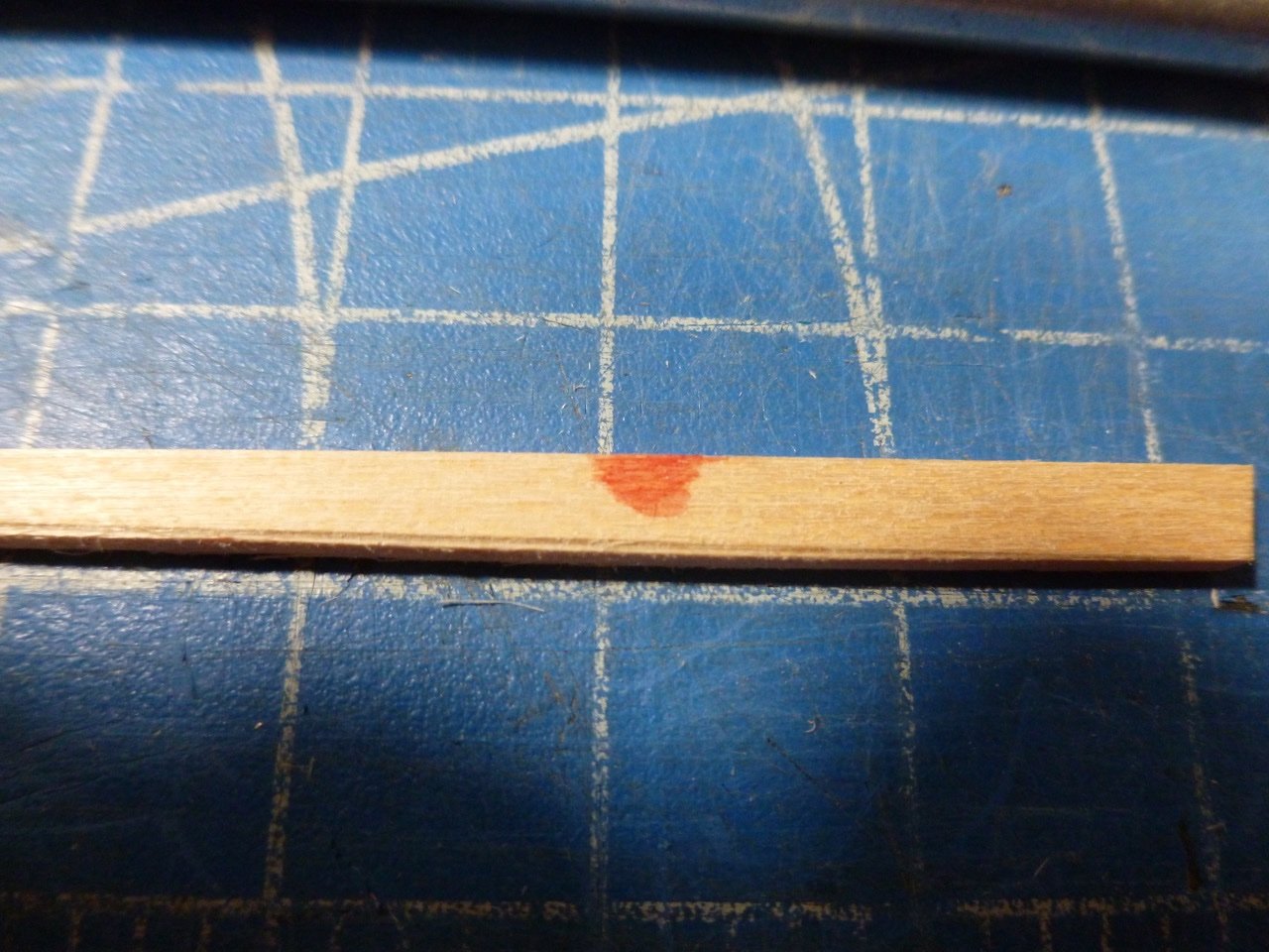
Andrew, Thank you for your interest and your kind comments. Real blood but it's on the inside of the plank so I used it 😁 . The workbench is my old professional drawing board which must accommodate whatever I need in 37 x 60 inches. Should be enough if I wasn't so interested in the next procedure that I forget to tidy up after the previous one. But a good housekeeping is in order now that the hull planks are finished. Steve
-
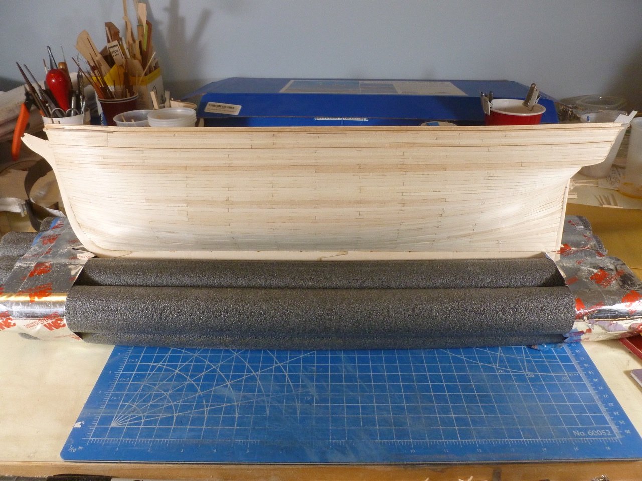
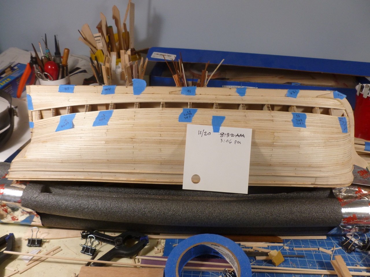
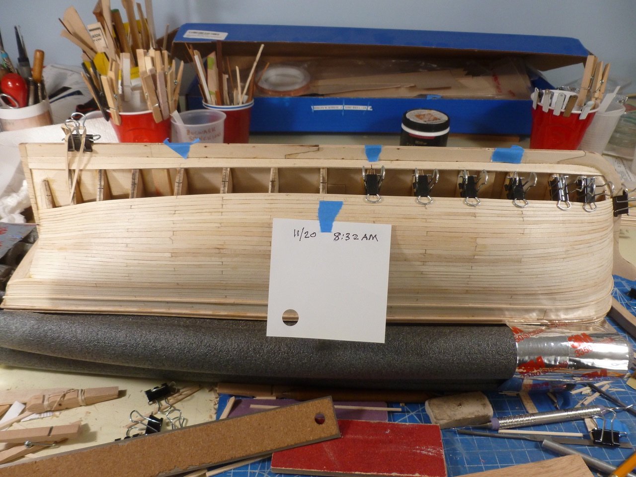
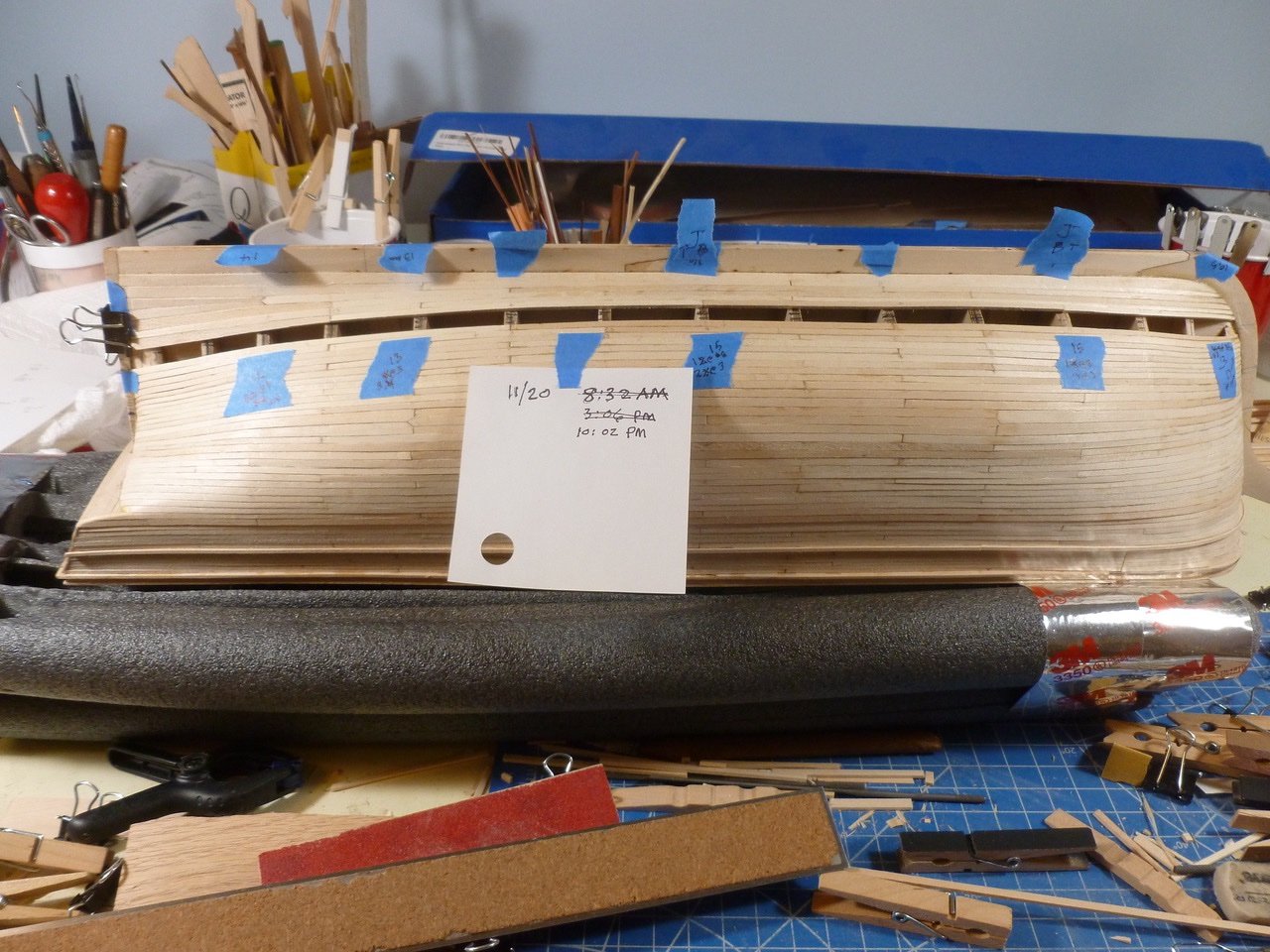
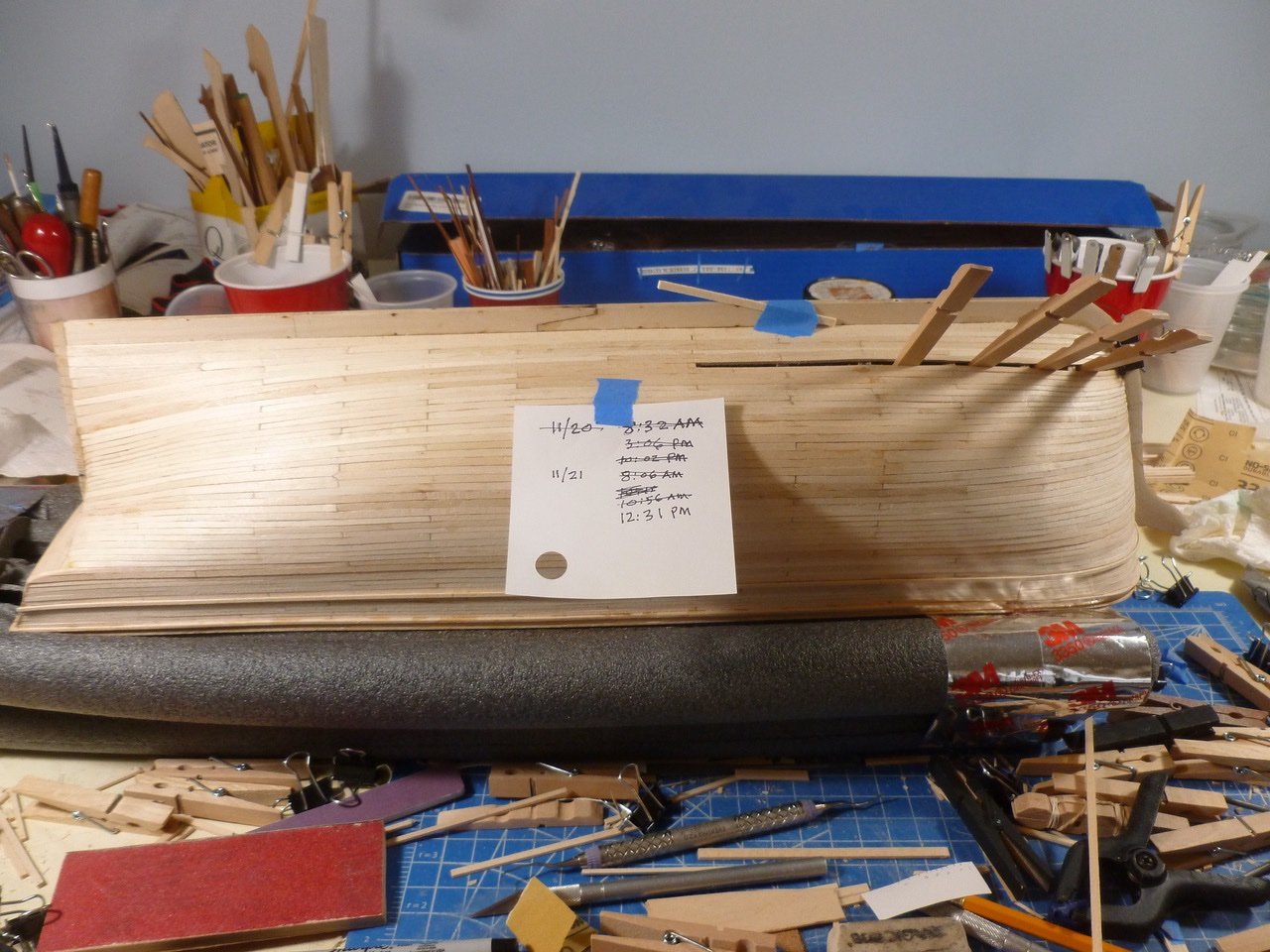
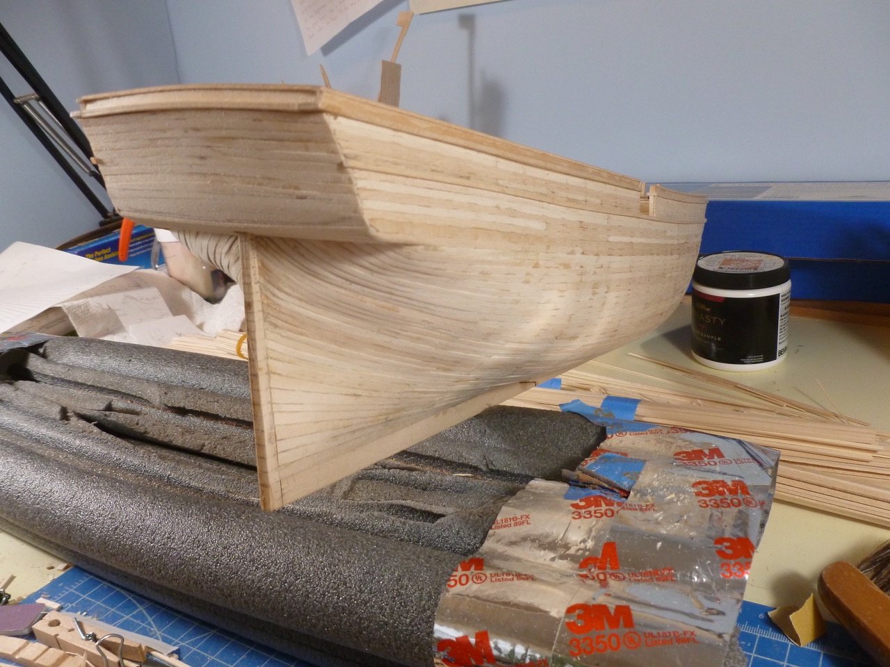
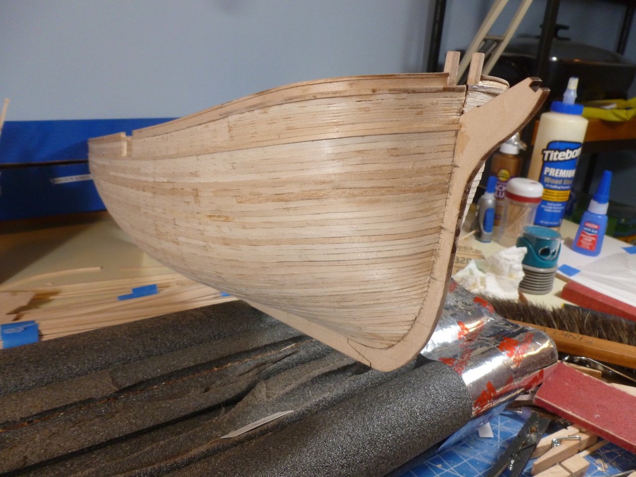
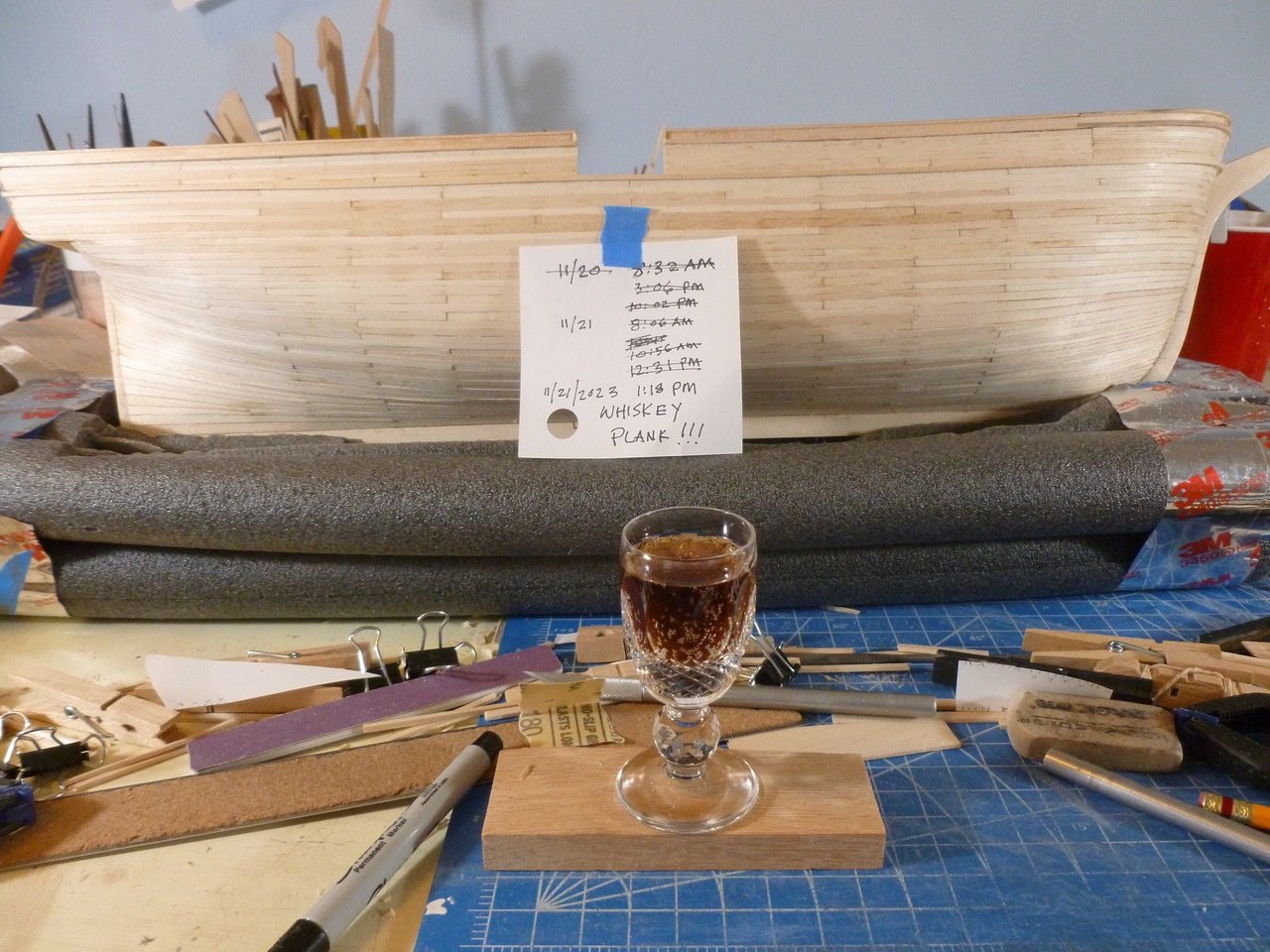
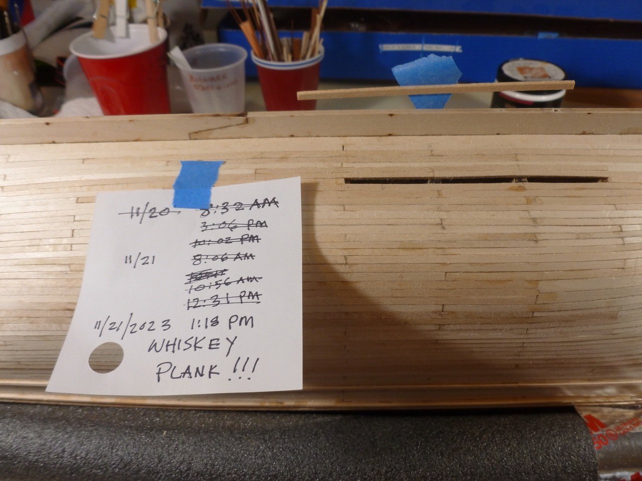
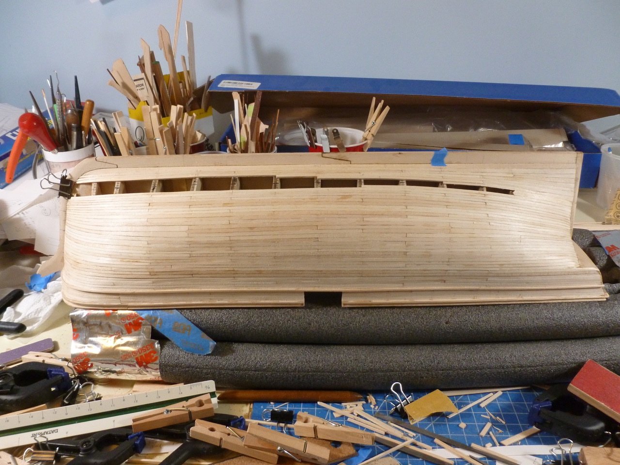
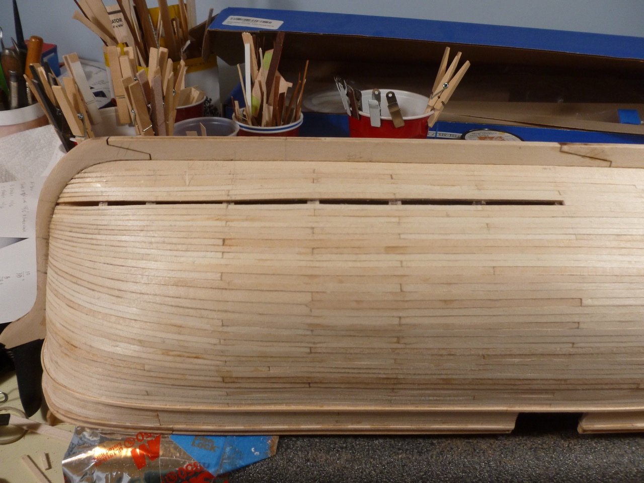
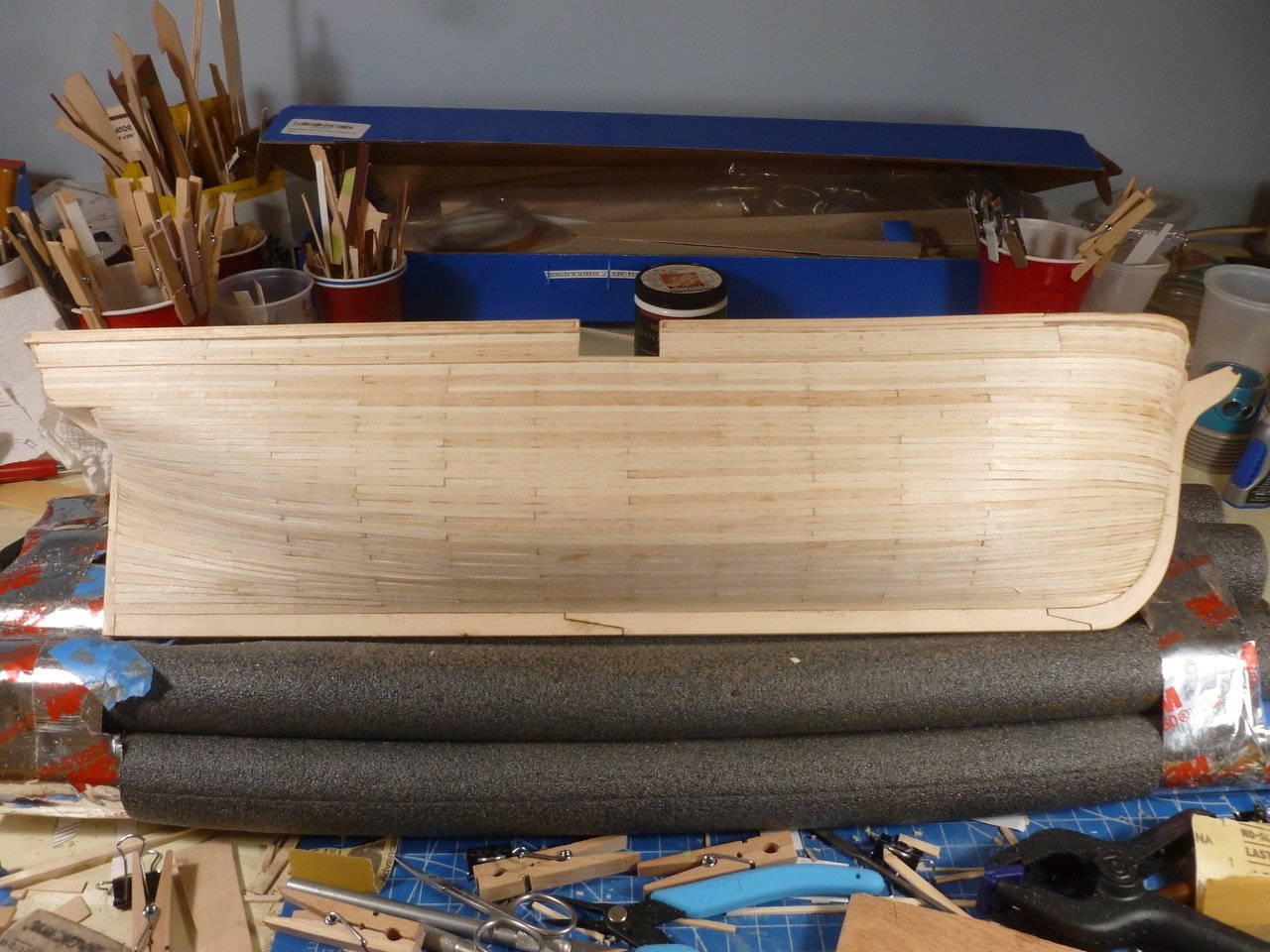
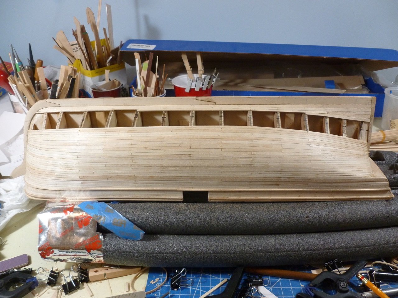
To those who dropped in or gave likes, thank you for your interest and support. Planking race to deadline There were always deadlines in architectural practice, either self-motivated (I need to bill something this month) or by the client (the students will be most upset if they don’t have a place to live in August). As they say in racing, when the flag drops the ___ stops. So I gave myself a deadline: Hull planked before Thanksgiving, with progress notices along the way. Here we go. Not letting a bloody plank get in the way I pressed on. Since 11/22 would be a baking day the deadline got pushed up and the whiskey plank arrived a day earlier than expected. Out came the celebration drink from the Admiral’s private stash of caffeine free diet Coke, in a suitably scaled crystal glass. The planked but unsanded hull is below. Some test sanding has shown that some planks are softer than others, a bit of a bummer when trying to avoid filler. Sanding will follow a little break for Thanksgiving. Dents will be attacked with drops of water followed by a steam iron. For those who celebrate it, I wish you and your families a safe and happy Thanksgiving. Thanks for viewing. Steve

-
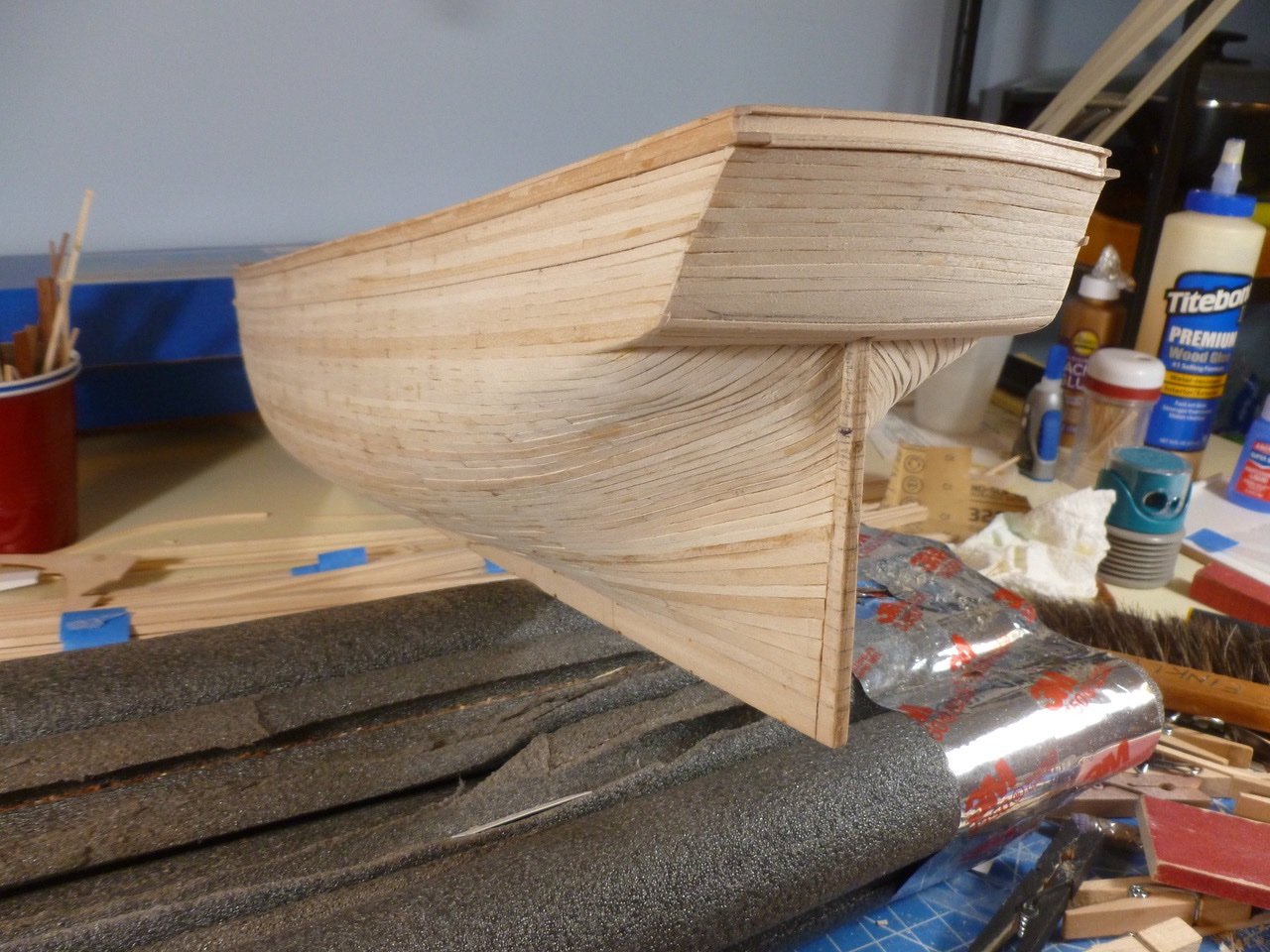
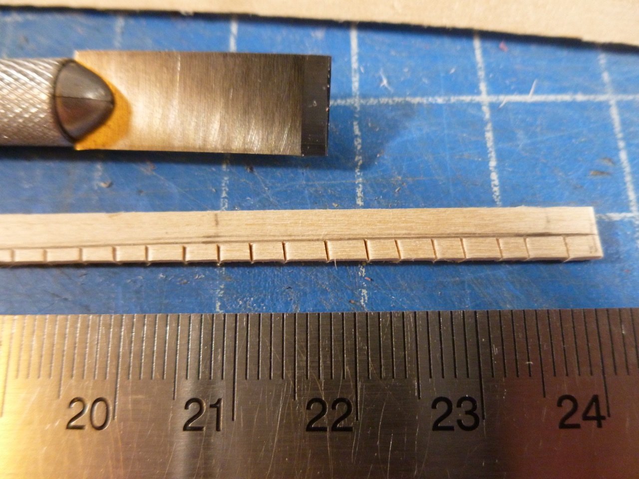
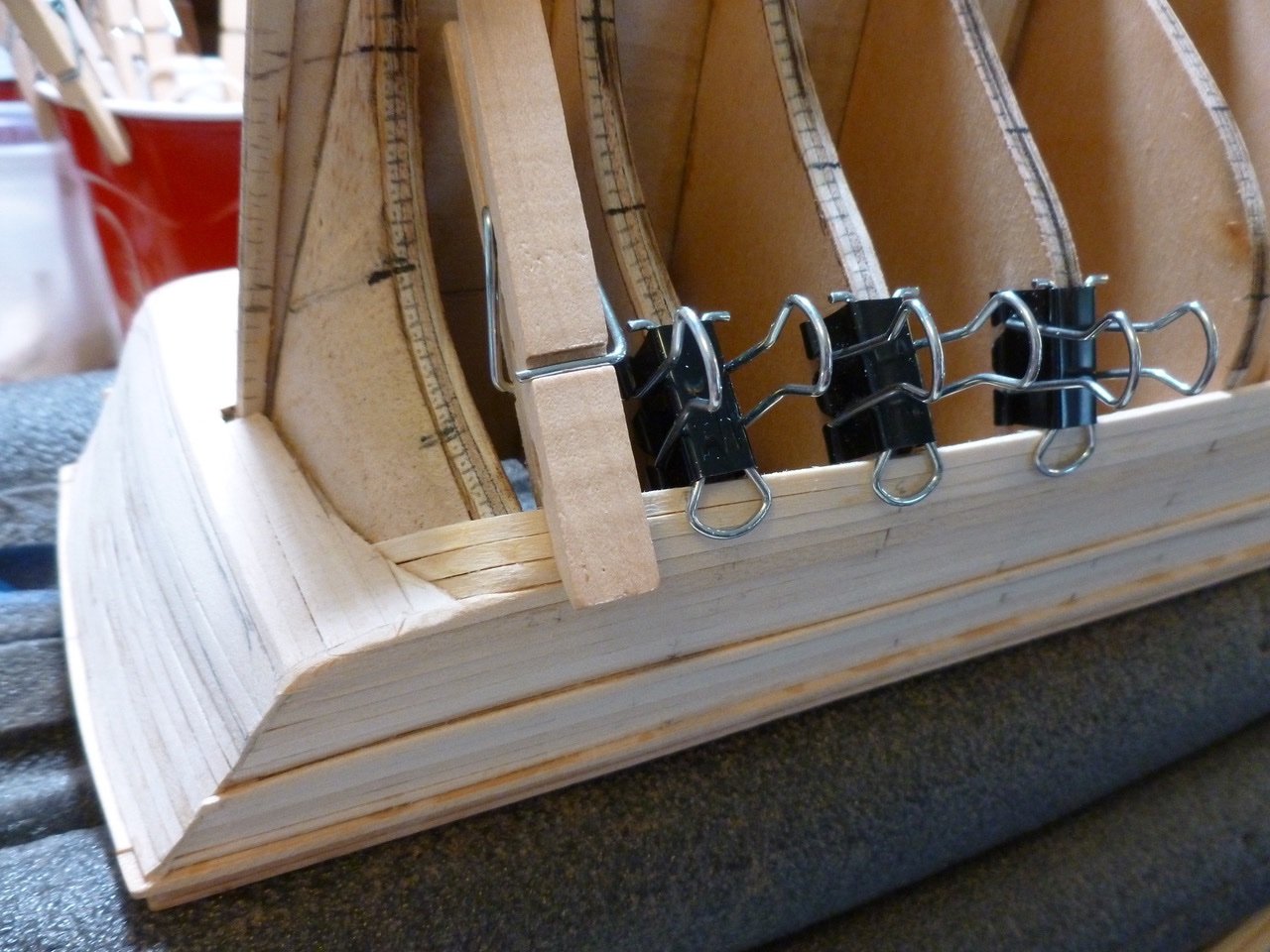
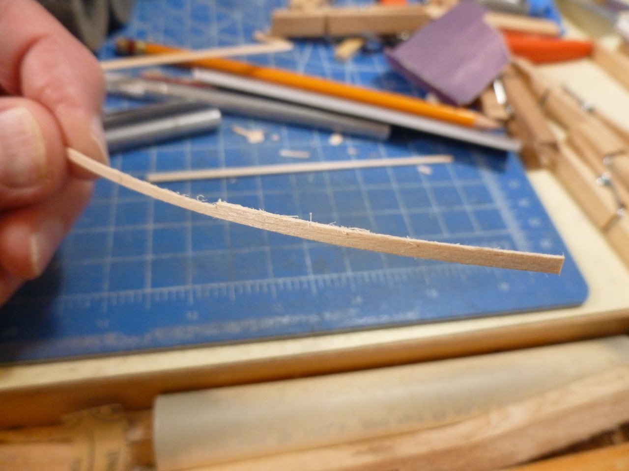
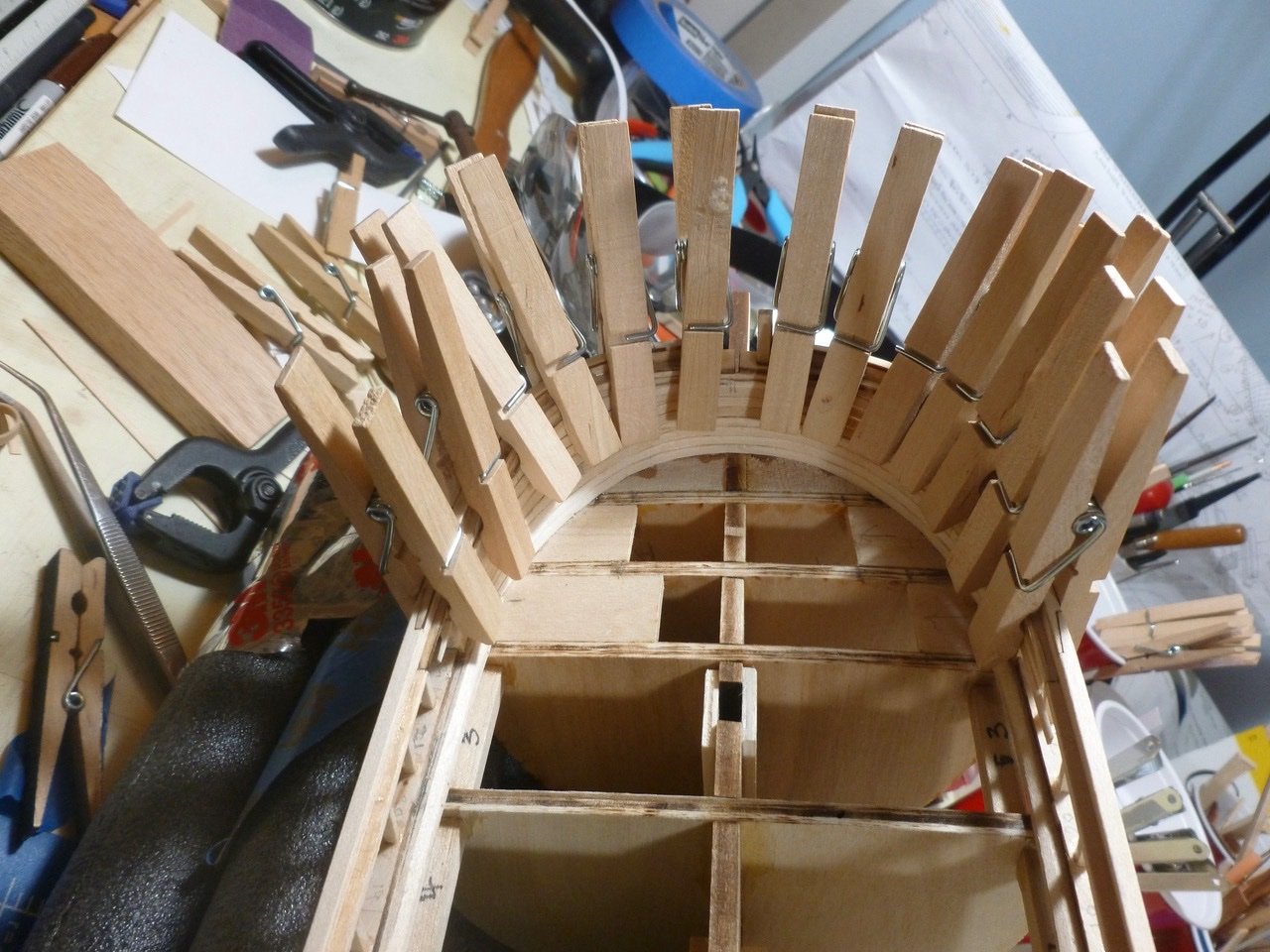
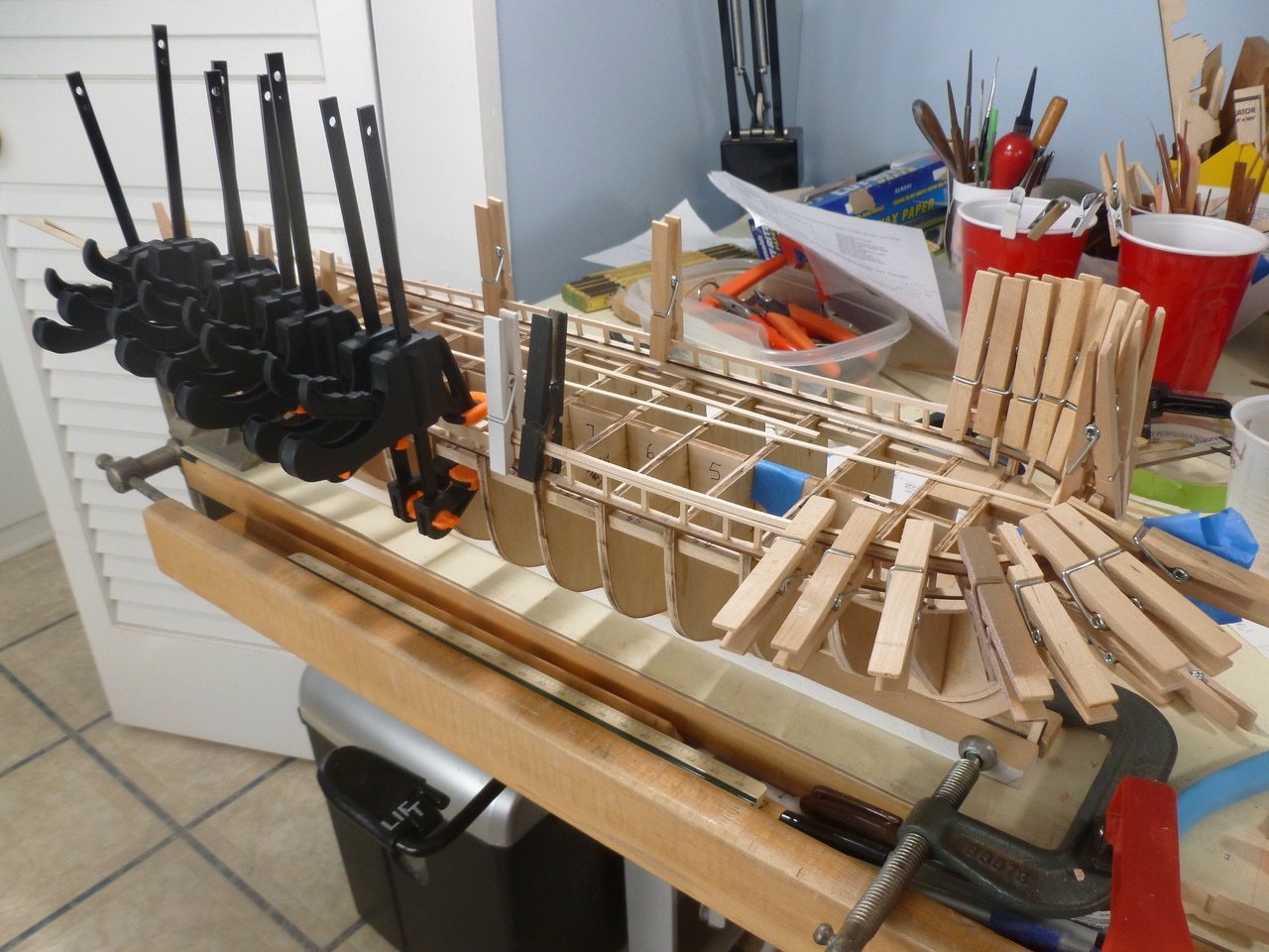
To those who dropped in or gave likes, thank you for your interest and support. Loracs, your kind words are inspirational. Thank you. Closing the gap. With so many little planks requiring tapering, and with no power mini-saw, I use a sanding block mounted in a little vise that has served me well for model ships as well as house construction, additions and renovations, a big dollhouse and anything else that required a firm grip. I notch and remove the waste with an X-acto chisel to reduce sanding time. As the gap in the starboard planking closes I use bits of clothes pins to wedge the planks in position. Of course nothing is foolproof. While removing a reversed clothes pin (handles in to apply pressure outward against the plank edges) I squeezed the exposed head ends which drove the handle end into the plank, creating a dent. Anguish led to immobility until I remembered a trick I learned from Mr. Bluejacket for removing dents. The general idea is to introduce steam to expand the dented fibers. I think the trick involved a drop of very hot water but I thought I’d try cold water followed by heating the dent with the electric iron. Worked great. So back to starboard planking closure. The pics below summarize the action. The starboard planking is complete. If the port side reaches a similar finish, and if both sides smooth up sufficiently with sanding, I might paint the hull rather than covering it with copper. A few more pics follow. On to completing the port side. Thanks for viewing. Steve
-
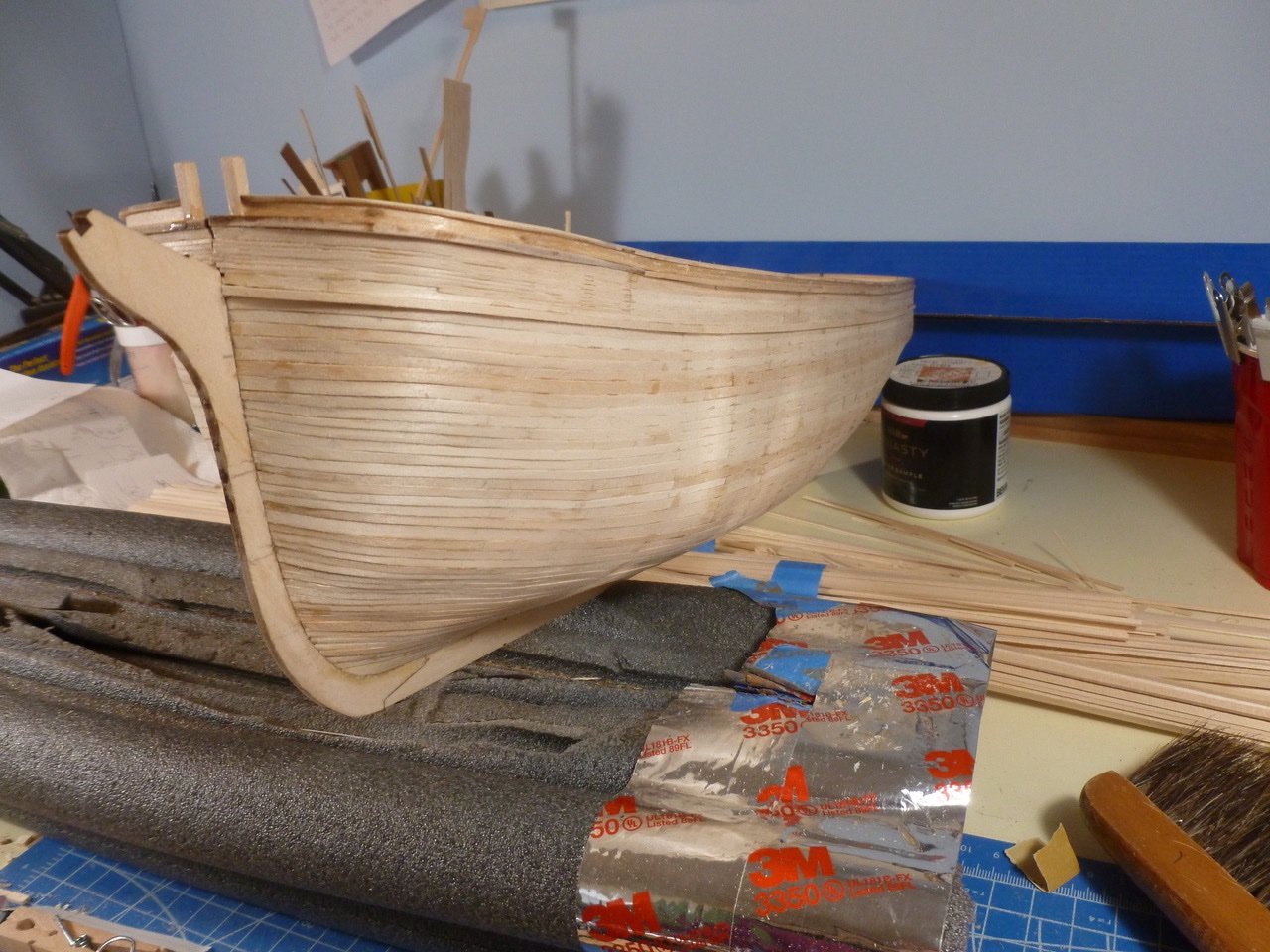
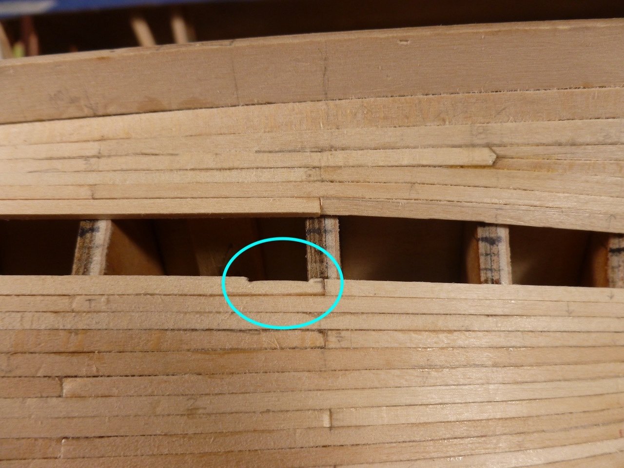
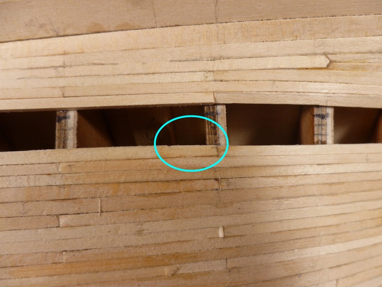
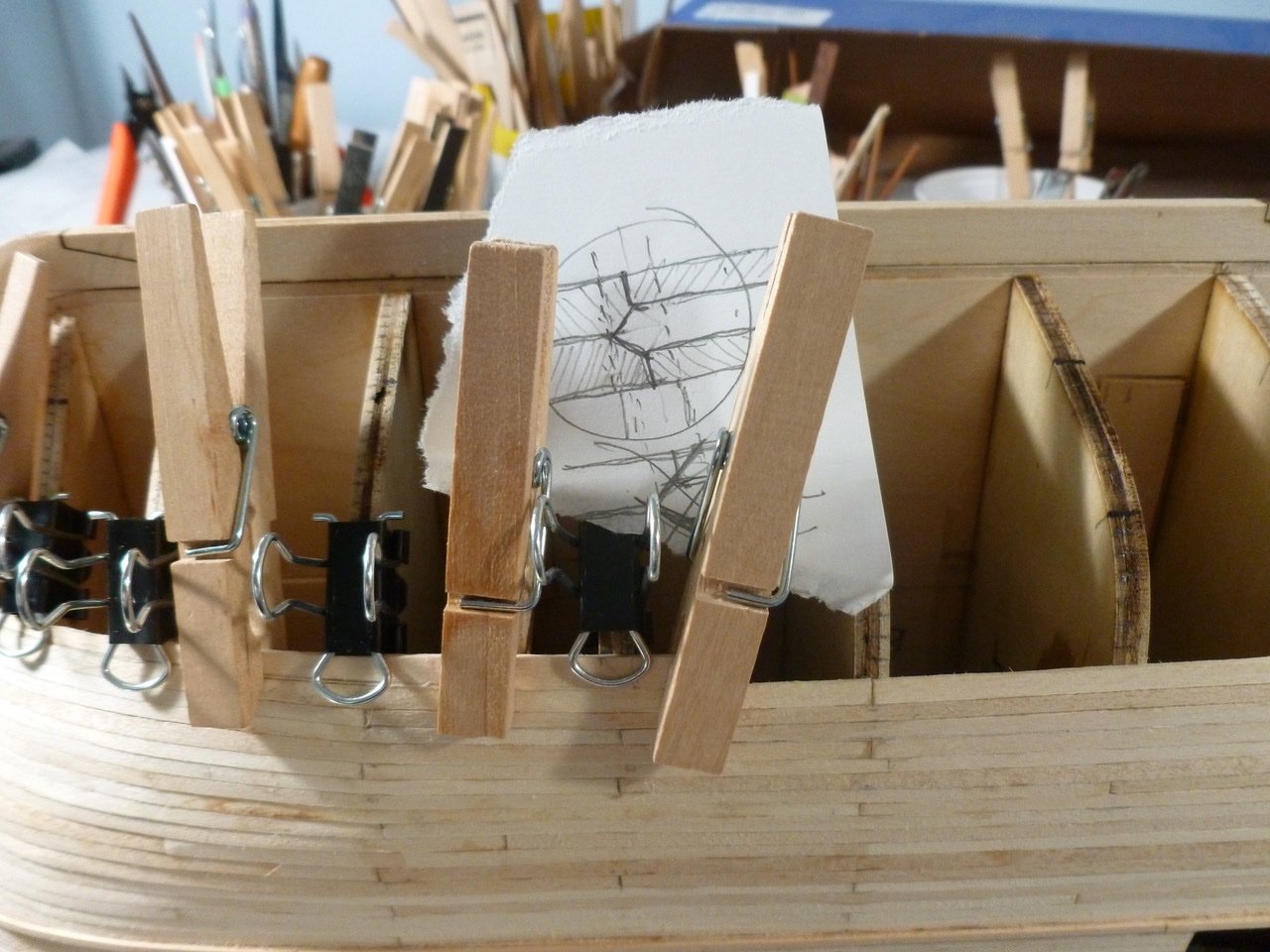
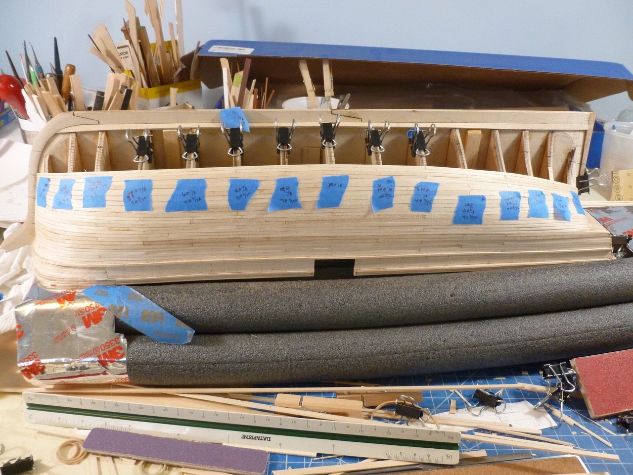
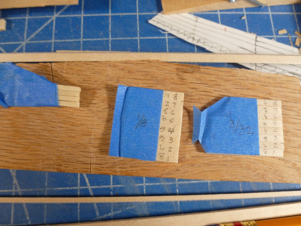
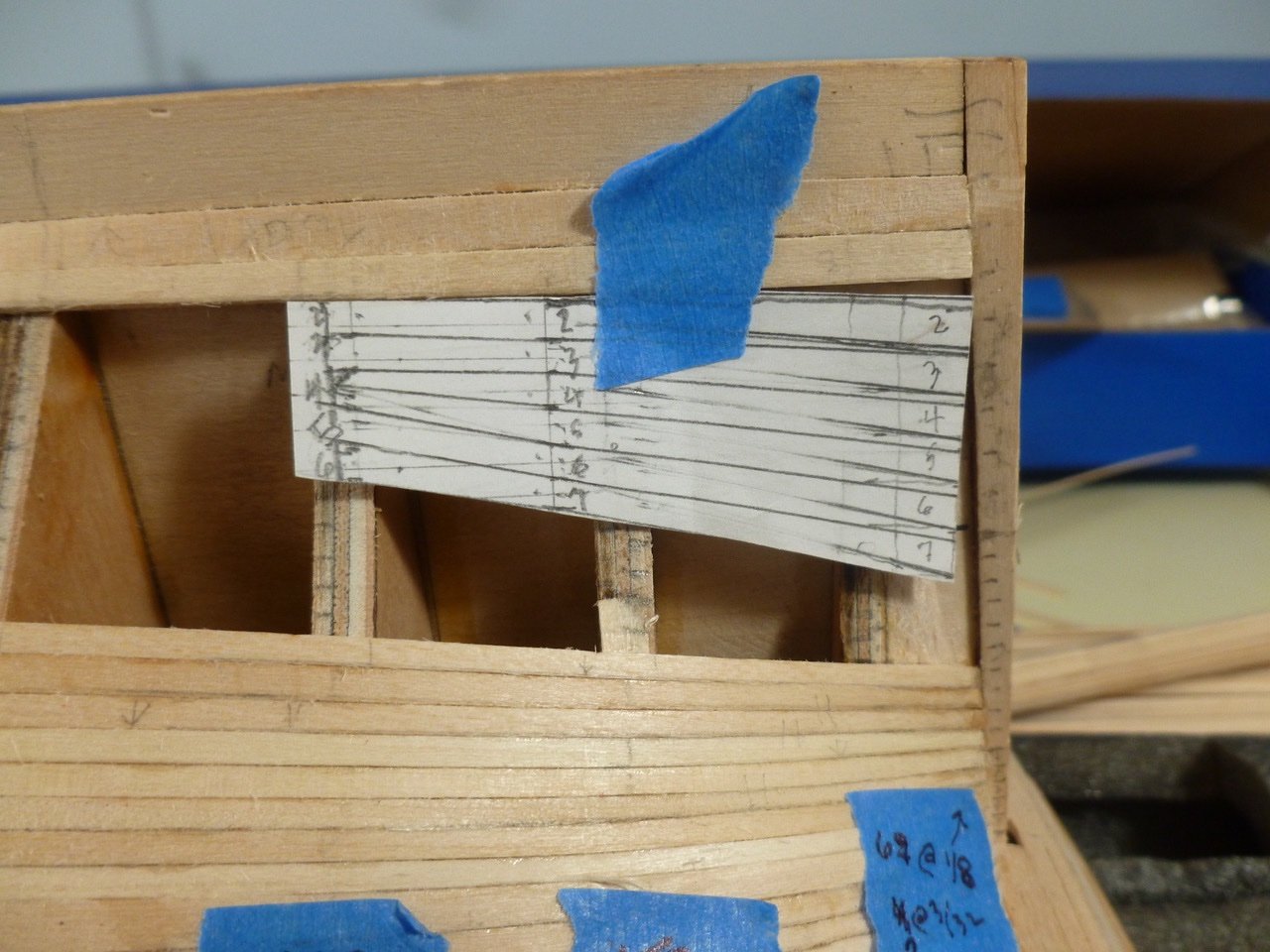
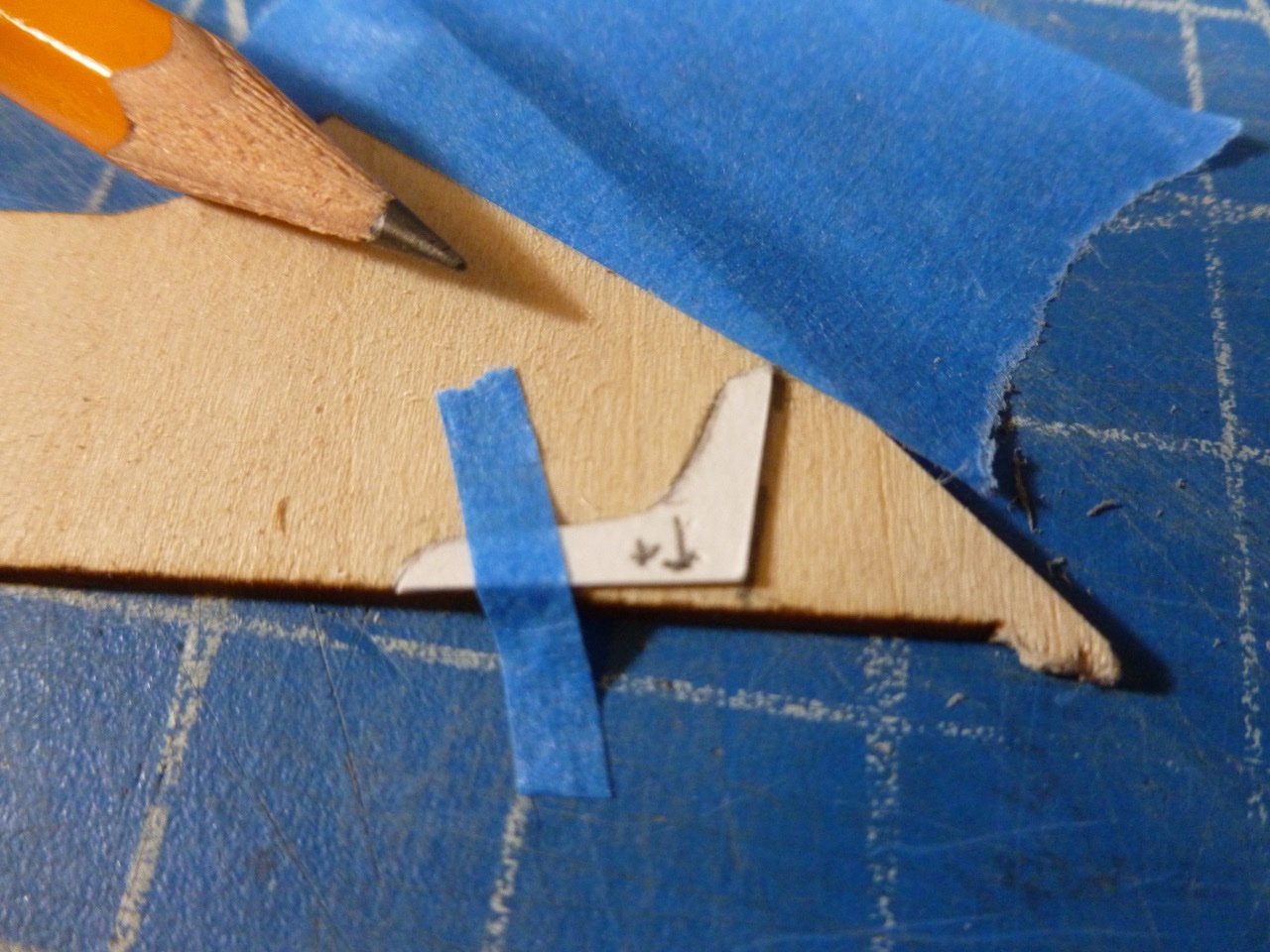
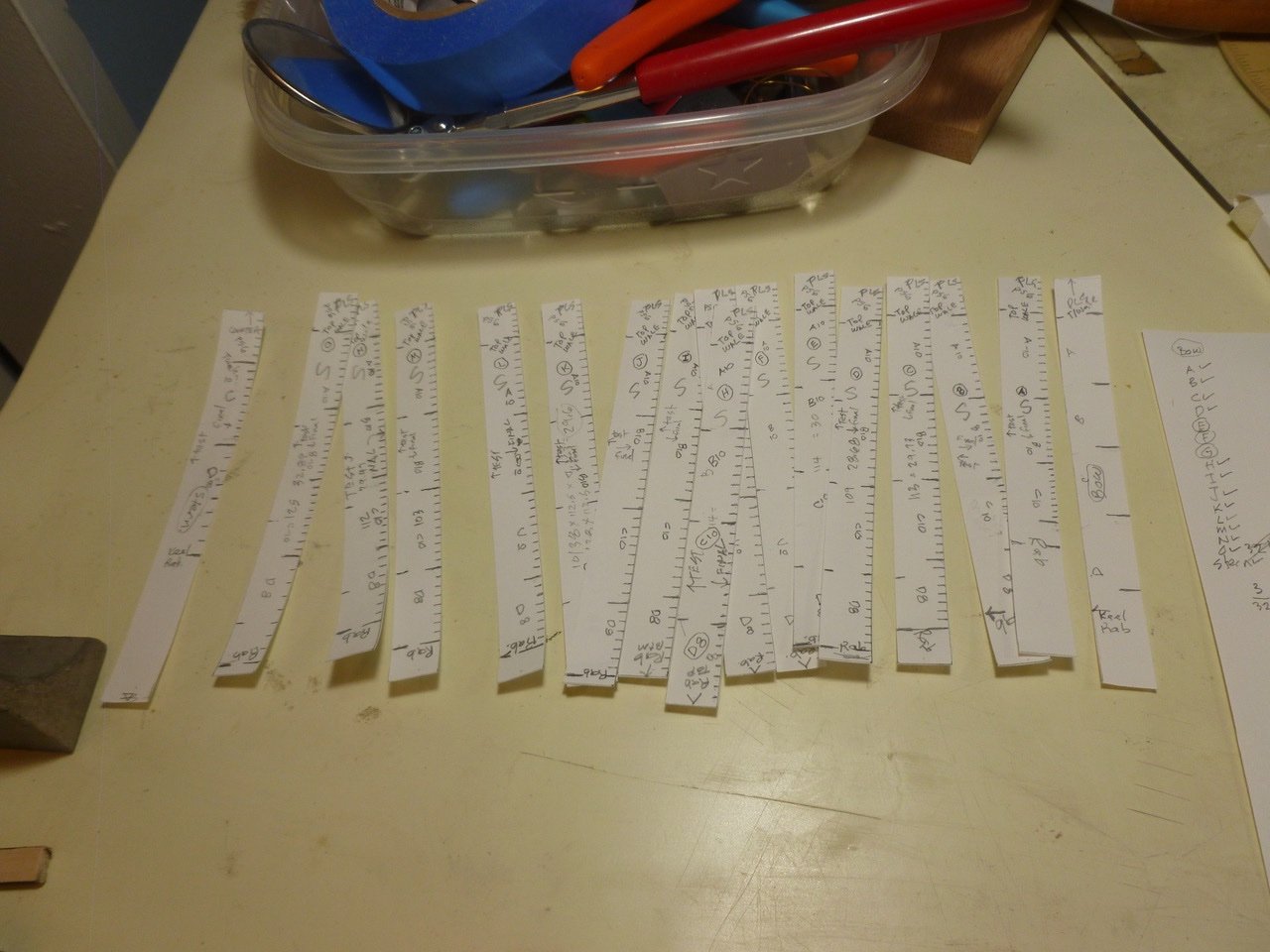
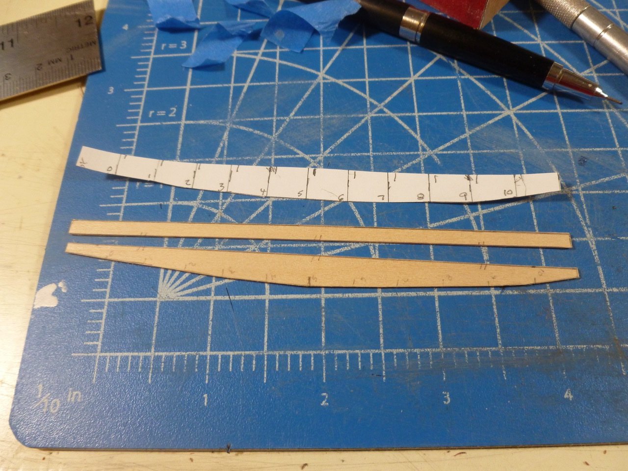
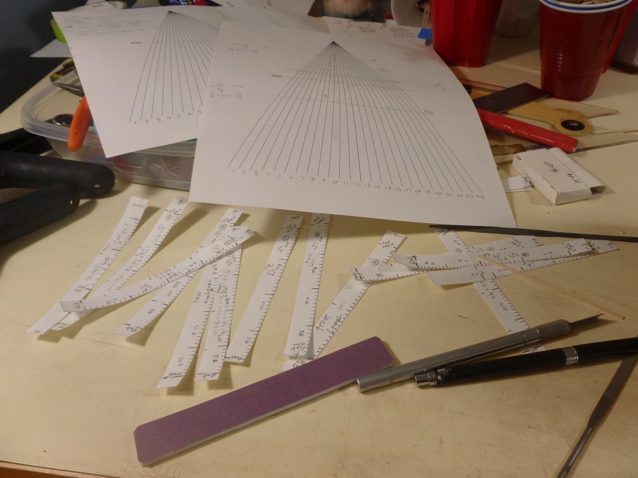
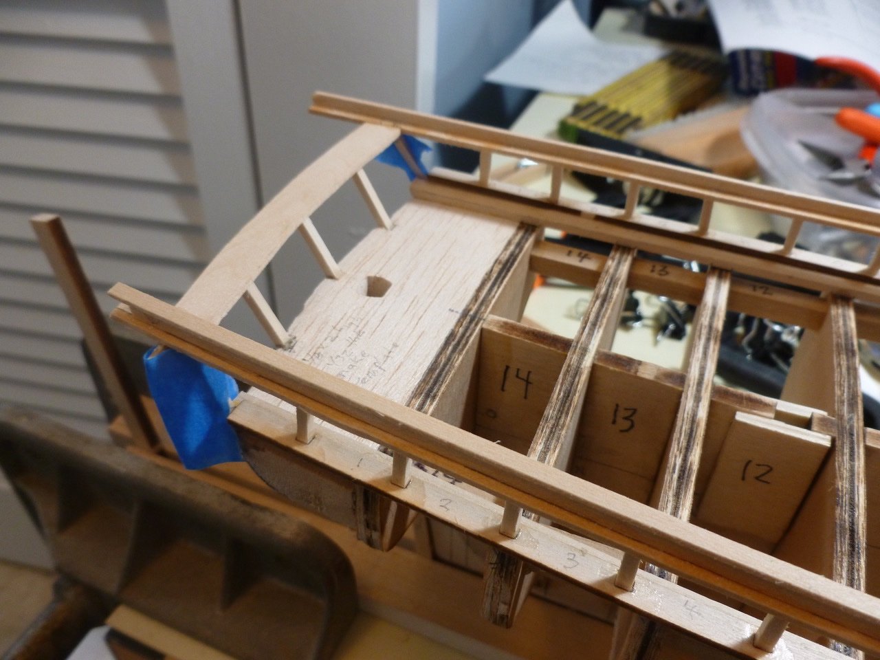
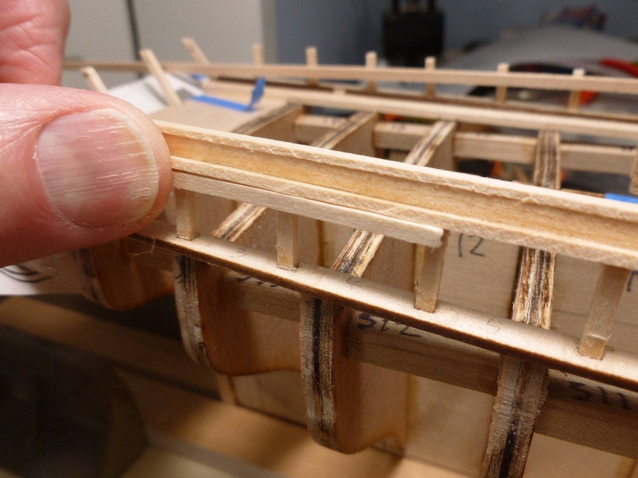
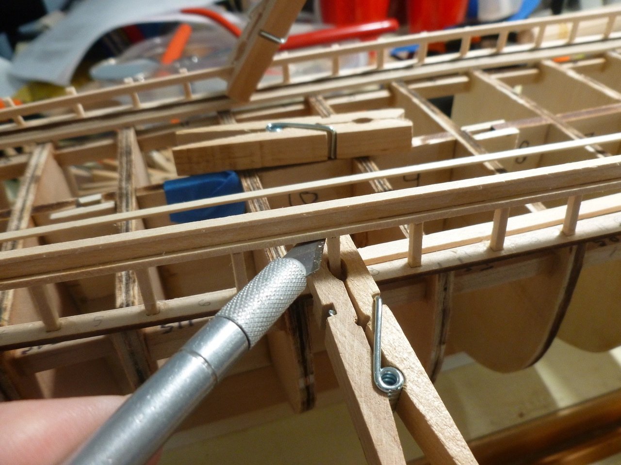
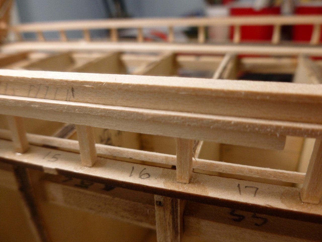
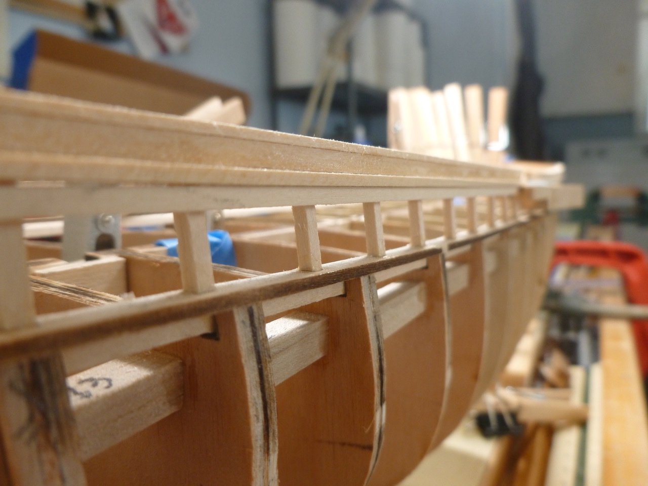
To those who dropped in or gave likes, thank you for your interest and support. Stealers and drop planks. Stealing and dropping. Sounds like my one and only stray to the dark side when Mom turned her back as we were leaving the five and dime store. I snatched a cookie from the display box near the front door, but rather than drop it I stuffed it in my mouth just as Mom reached over to take my hand. Seeing my bulging cheek she asked if I had taken a cookie. I tried to deny it but the crumbs spilling out of my mouth gave me away. There followed a stern conversation with the cookie lady after I tearfully pled guilty, with threats of incarceration (Mom was with the prosecution on this one) if I ever did it again. I’ve been on the straight and narrow ever since. Bits of taped up planks (plank testers?) proved invaluable in planning next steps. I numbered them from both ends to allow easy reading whether the blue tape hand hold is on the left or right. For bands where two sizes are needed, the pieces can be placed against the bulkhead and slid past one another until the fit matches the space. Using the plank testers I added a piece of tape at each bulkhead, marked with the mix of small and larger planks. For some unknown reason the aft stealer layout has been a mental block but with the help of a sketch it’s now installed. I’m finally in a rhythm of sorts for bow planking: Rough cut plank to length, mark spile width at each bulkhead location, sand plank taper, sand plank back bevel, wet and iron plank to form to the lateral and horizontal curves, make trial fit and clamp in place, remove clamps and hang with CA glue. Rinse and repeat (does anyone really follow the hair shampoo directions?) I used a 3/16” plank for the garboard, full width from end to end, keeping the bow end straight into the stem. There is one drop plank forward (so far). Aft there is one drop plank to help the narrow bits, and one stealer where the planks fan out. I’m getting a bit giddy as the starboard planking nears completion, but only a bit since I still have to finish the port side. Hopefully lessons learned will make it quicker. Thanks for viewing. Steve
-
Mike, thanks for your feedback. I'm still trying to decide on copper plates versus paint so I'm working to keep the planks as good as I can. Diver, thanks for your interest and kind feedback. The installed planks from the top of wale downward are either 1/8" [3.18mm] (midship) or 3/32"[2.381mm] (fore and aft so far) wide. Both are 1/16"[1.587mm] thick. The instructions imply that some 3/16"[4.762mm] wide planks may also be required where the plank runs are wider near the stern. I'm just now getting into that area. The planks between planksheer and main rail were a mix of 1/16"[1.587mm] and 1/32"[0.793mm] wide. Good luck on your tug. By the way, the model scale is 1:64 (3/16" = 1'-0"). Steve
-
Mike, thanks for stopping by and for your kind feedback. Did you get into stealers or drop planks? Near the aft end It looks like I could work without stealers but at the expense of quite narrow planks (half width, or less, of 3/32 inch strips). I have used both stealers and drop planks on previous builds but wondered what others have experienced on CWM. Thanks again. Steve
-
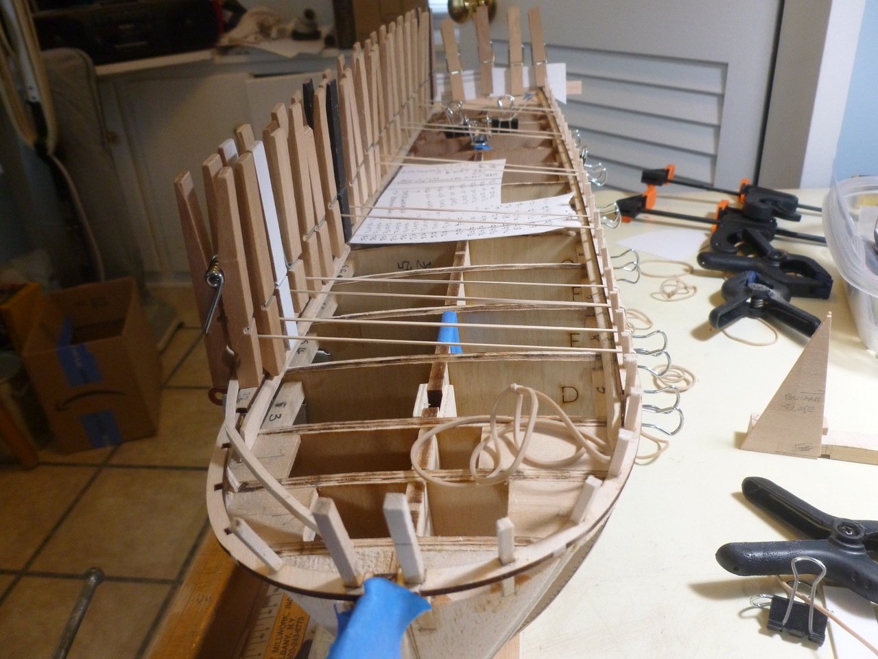
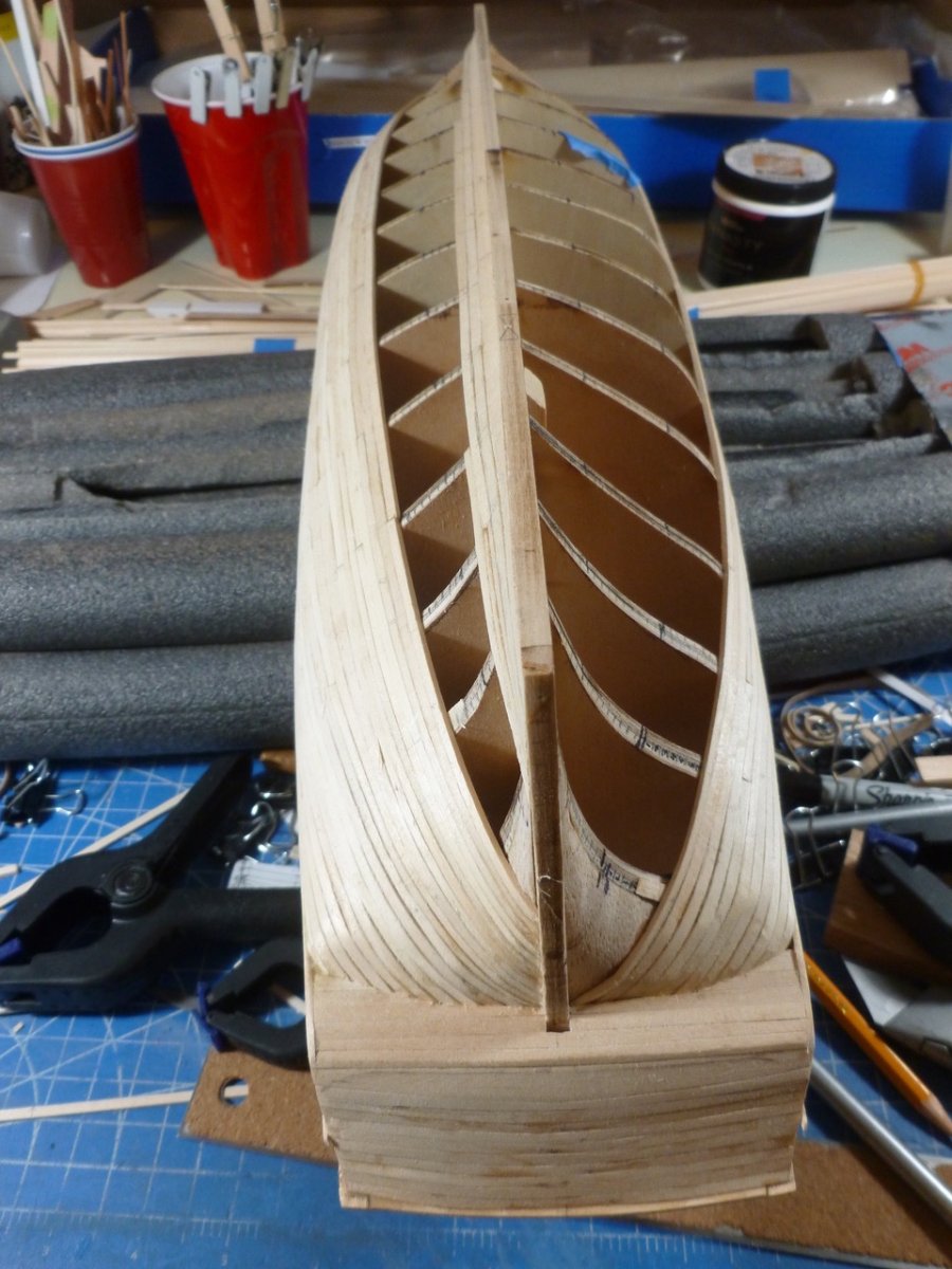
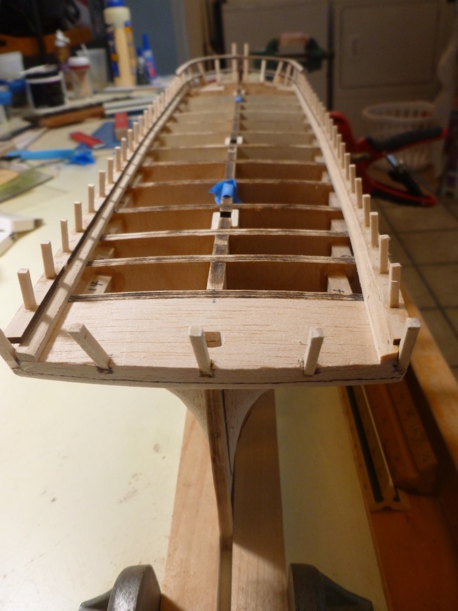
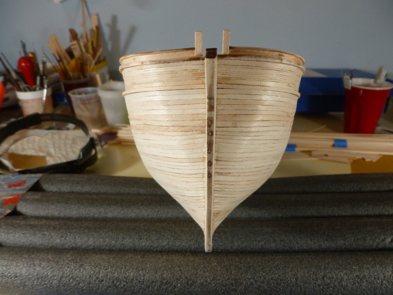
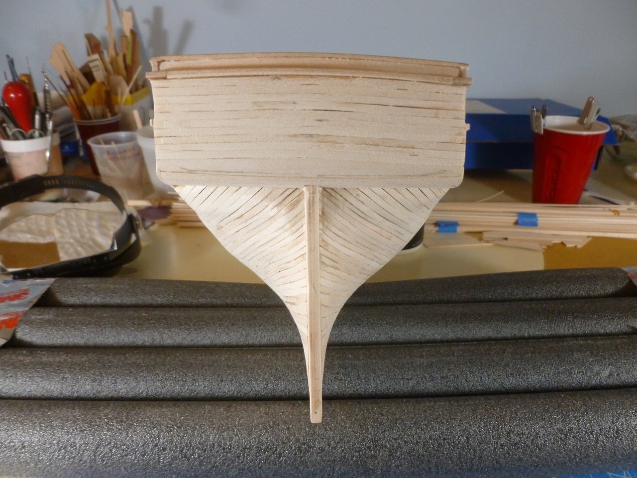
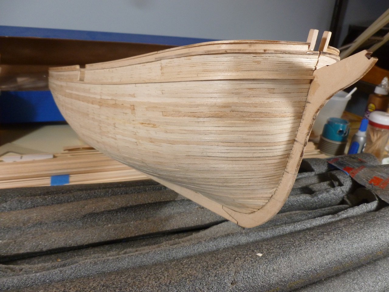
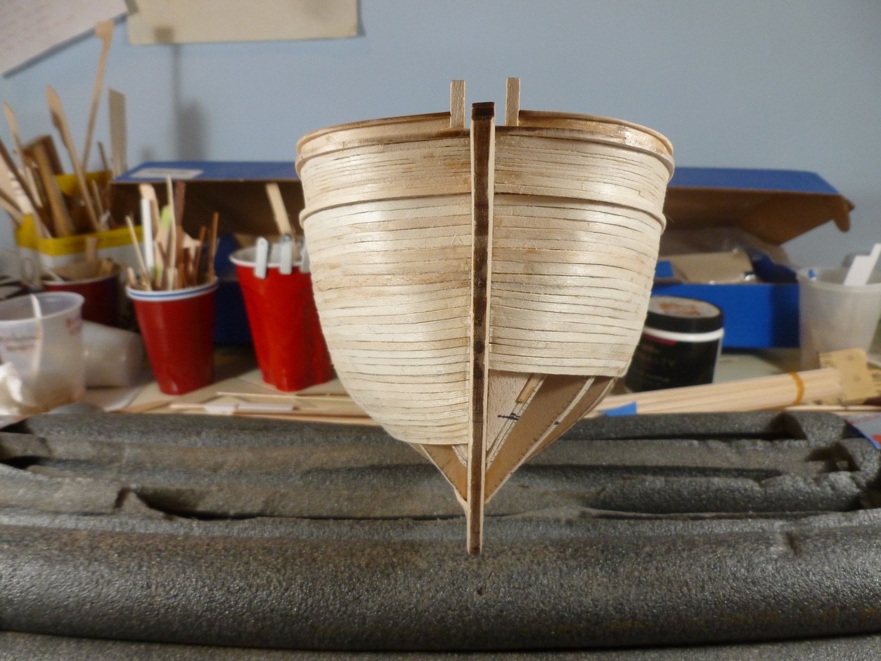
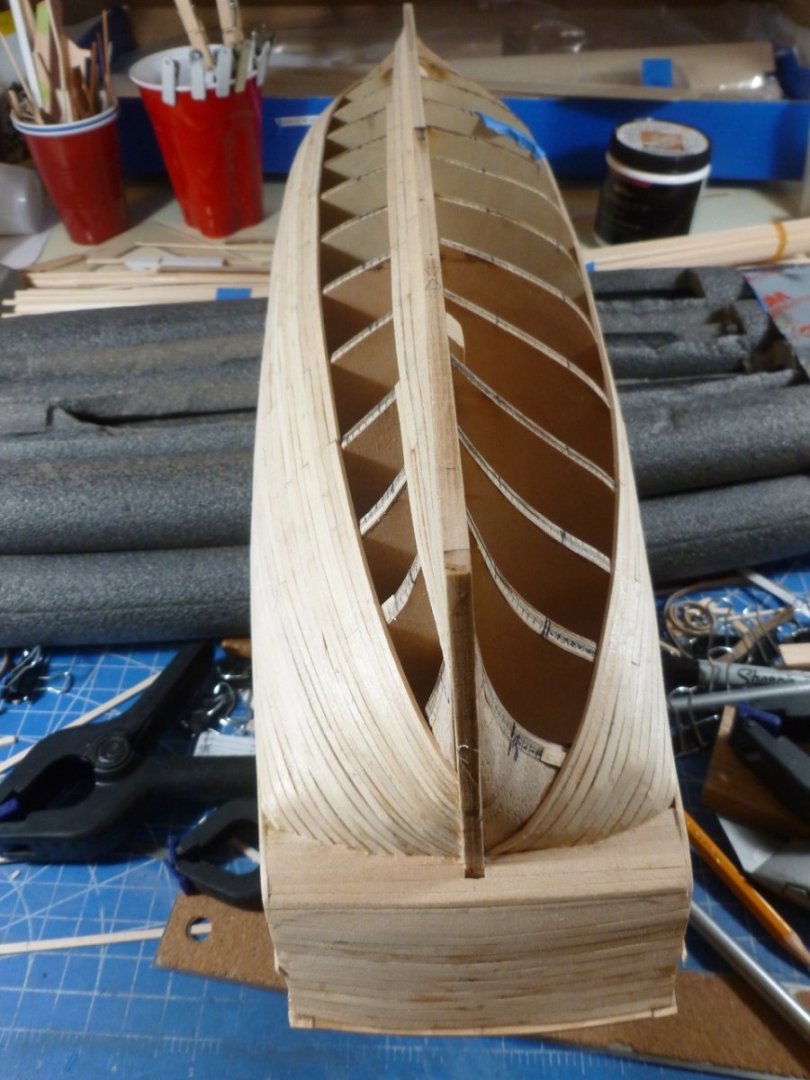
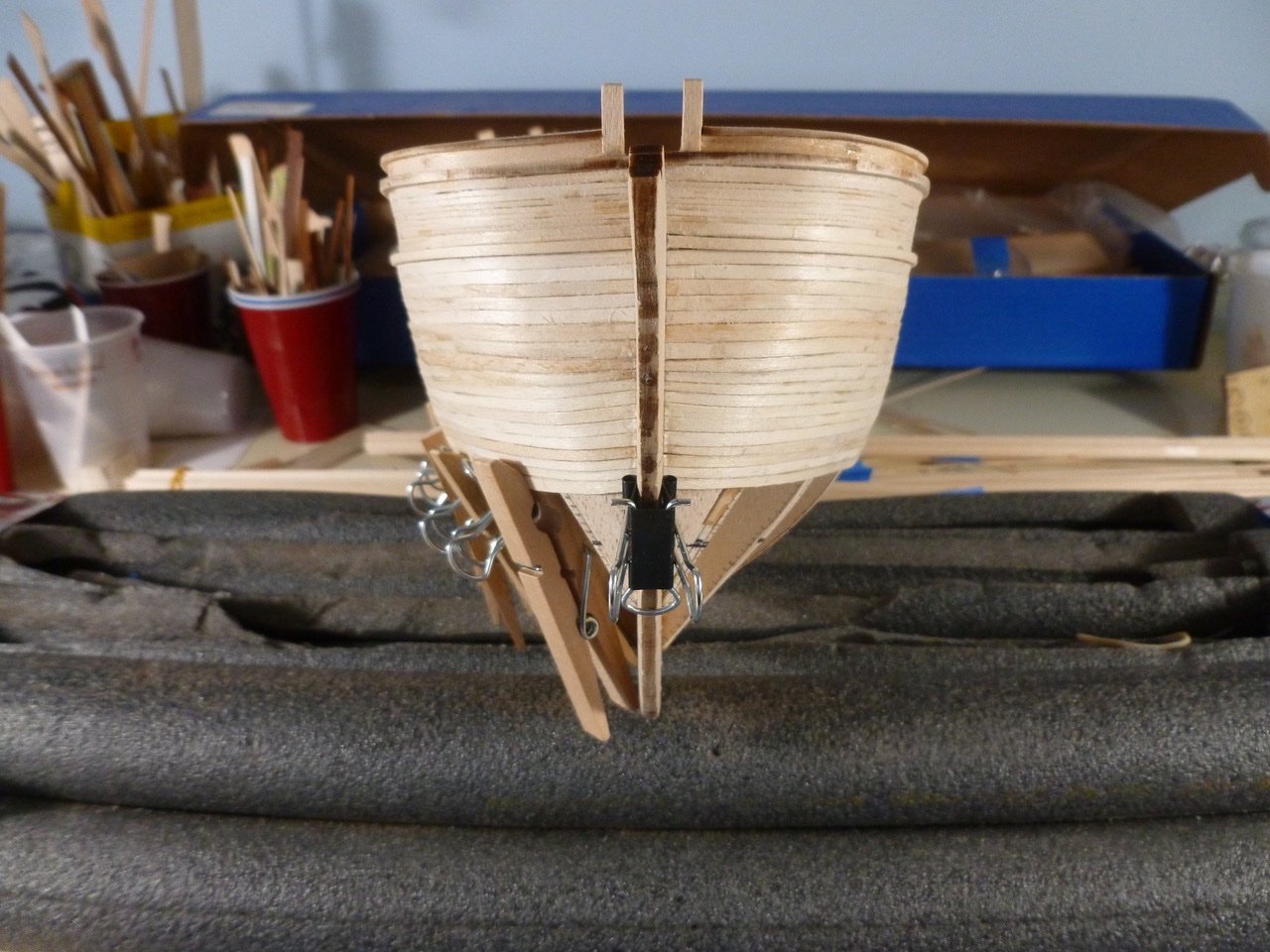
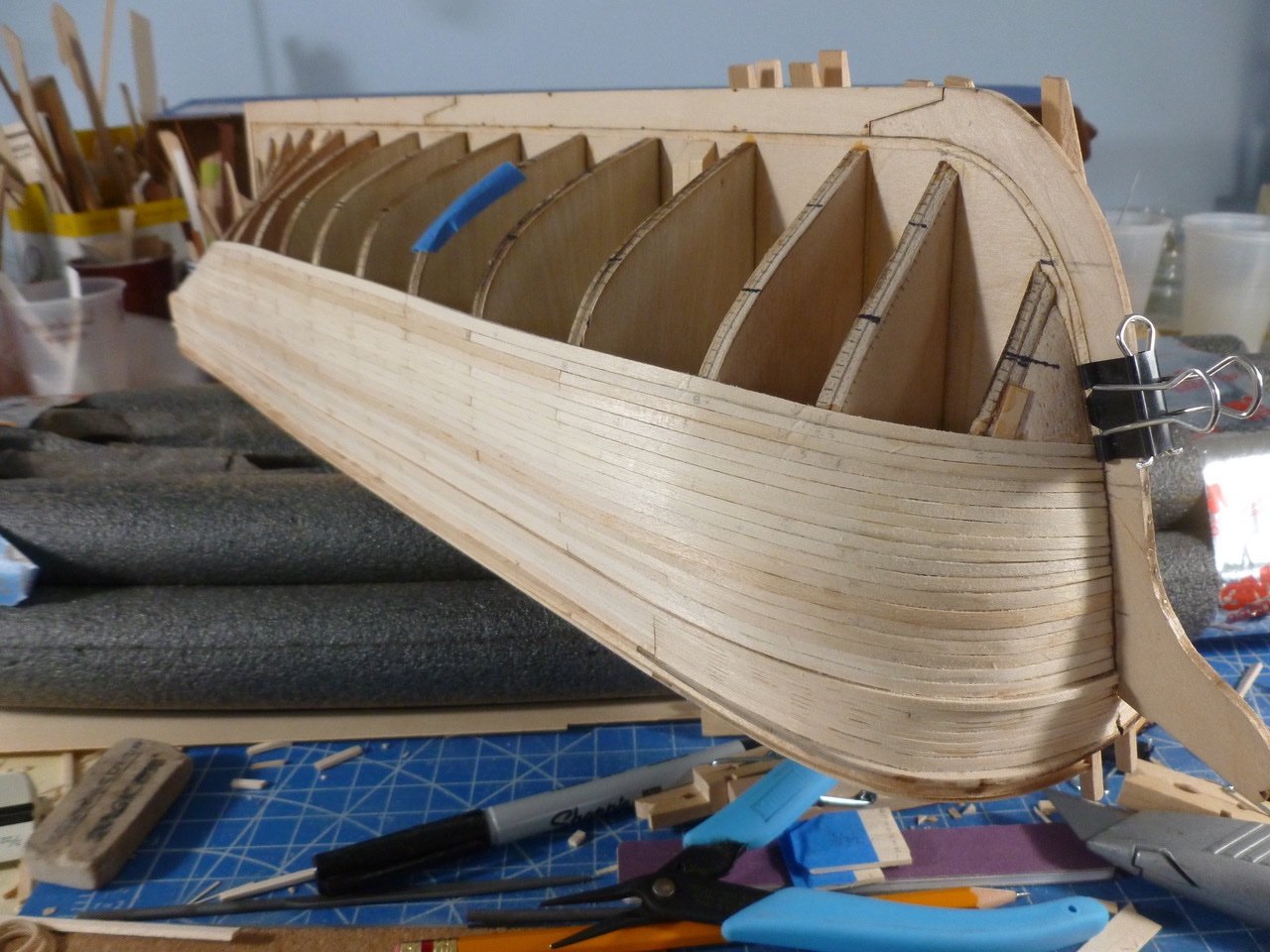
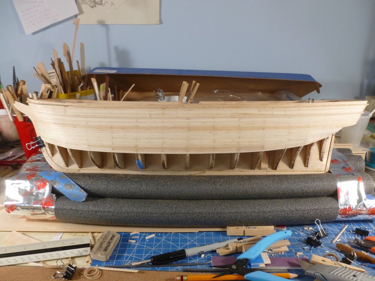
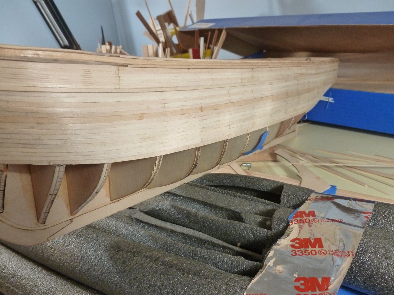
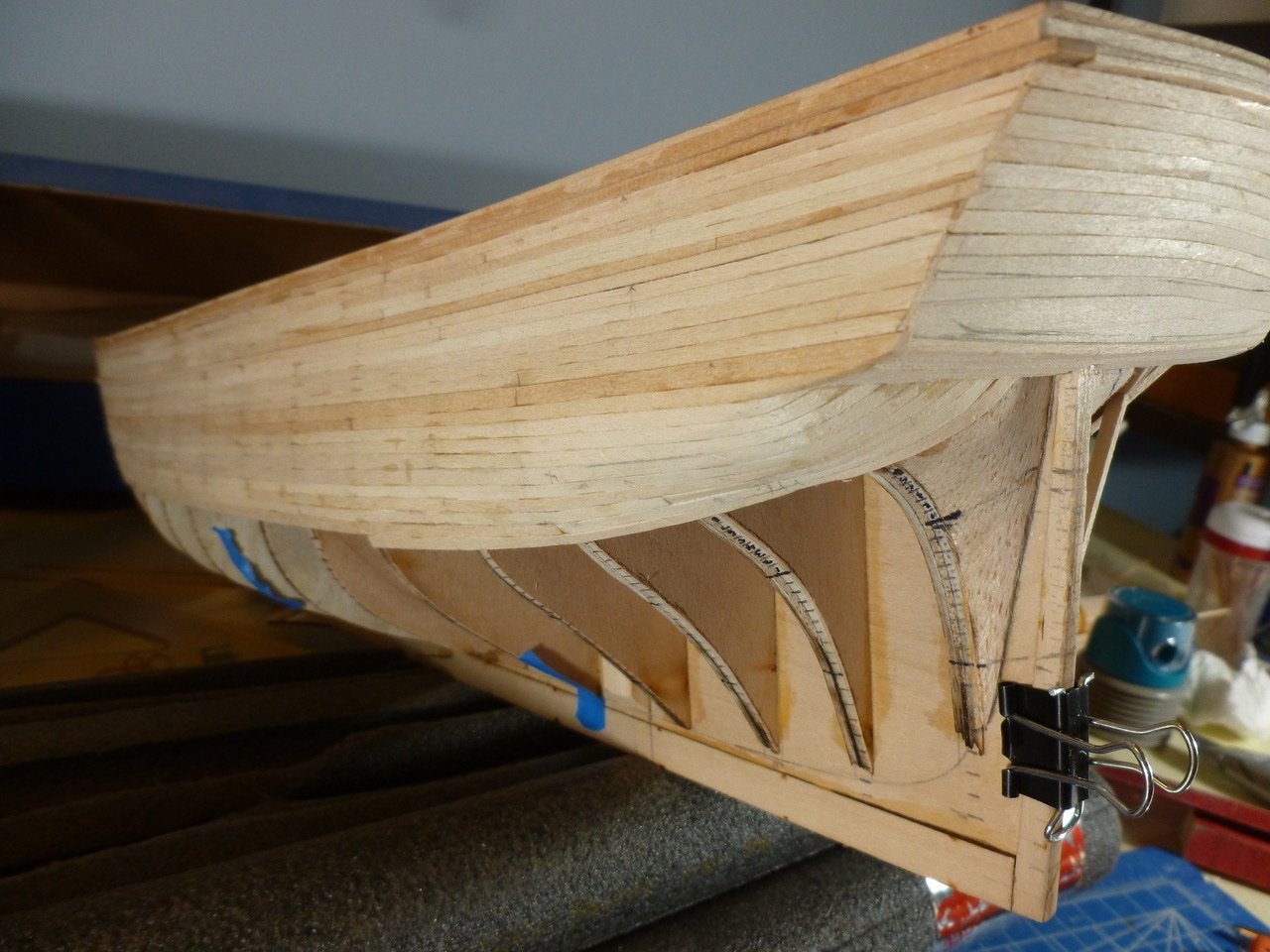
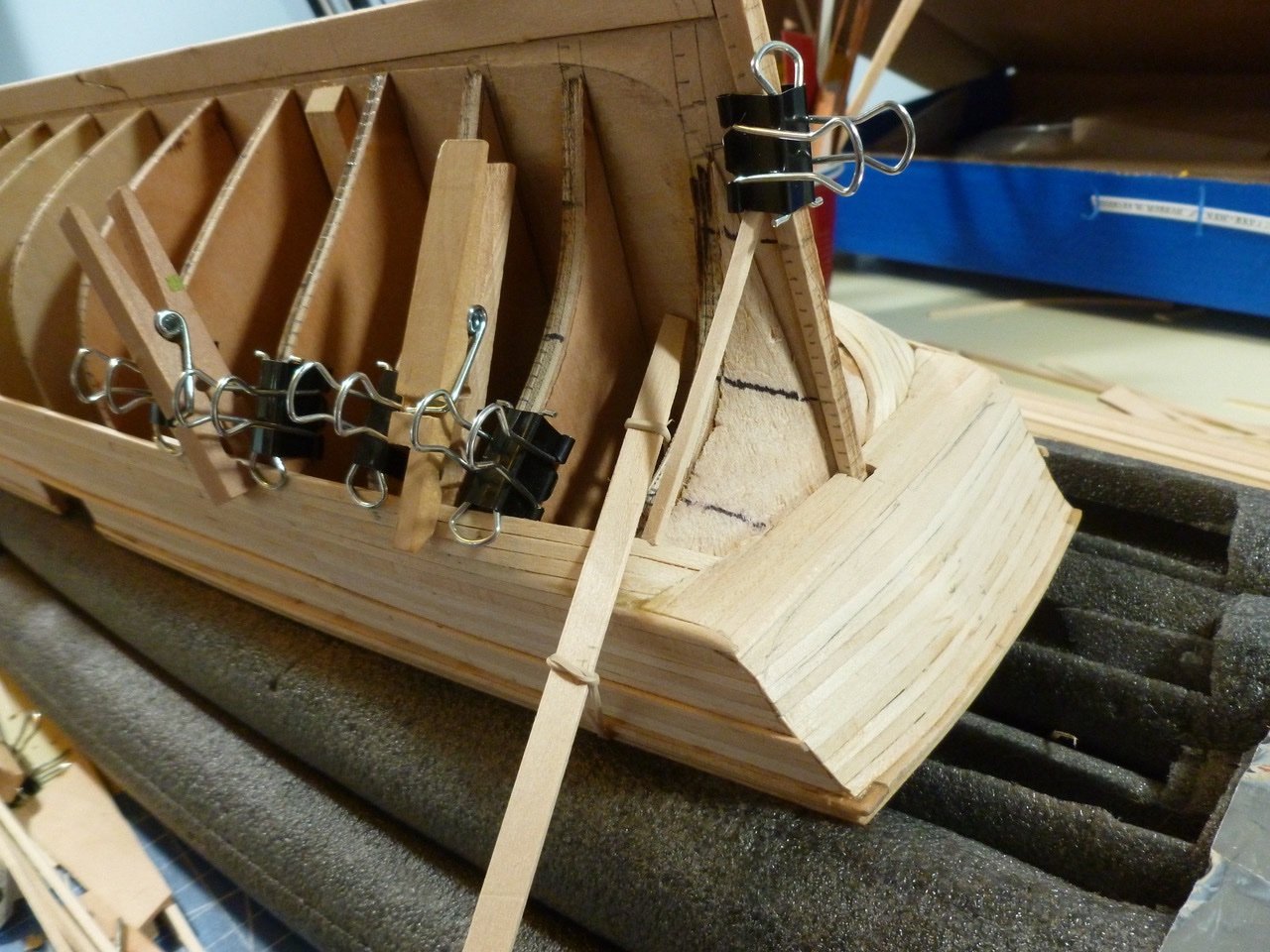
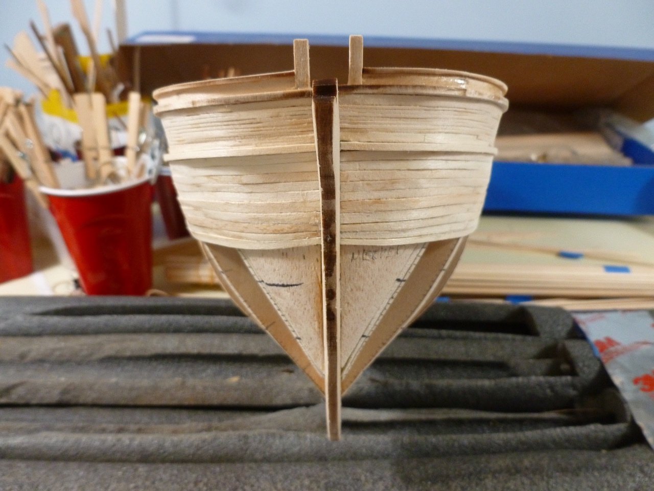
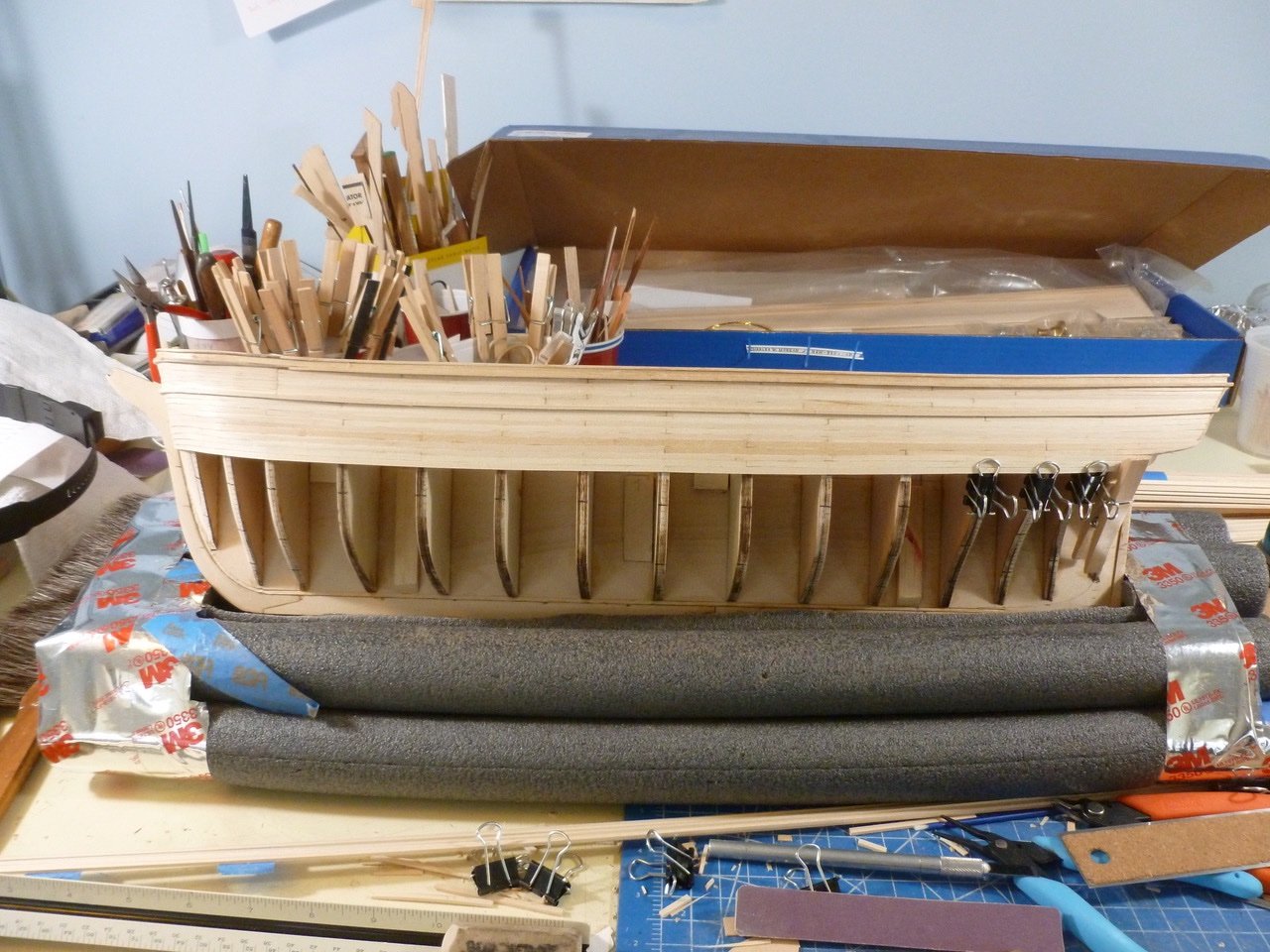
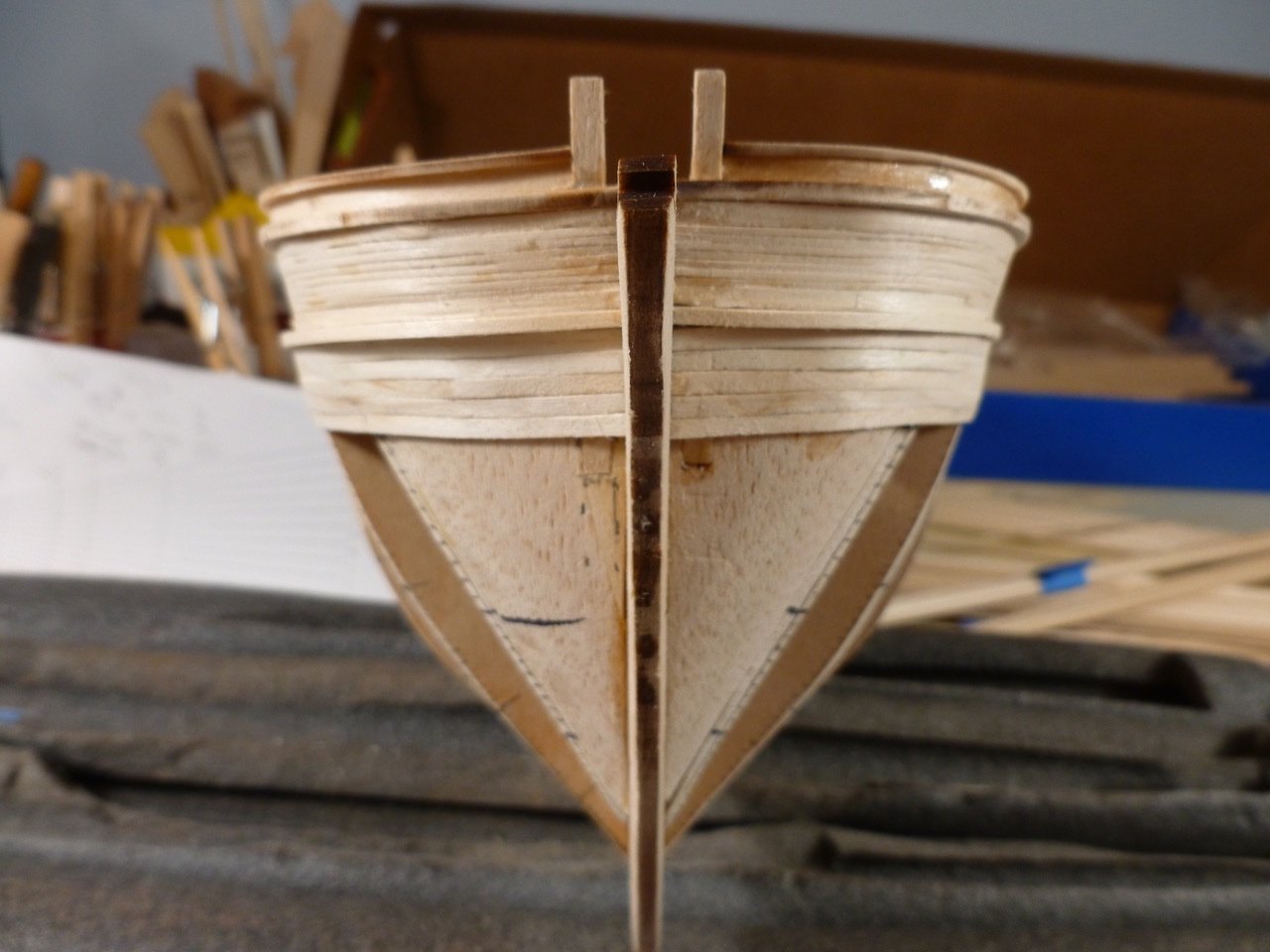
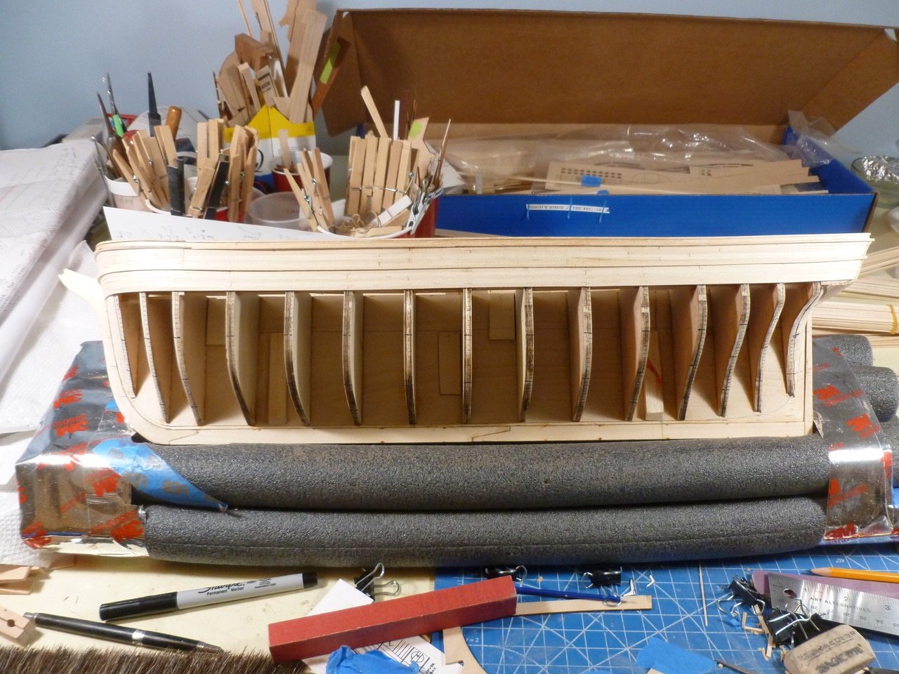
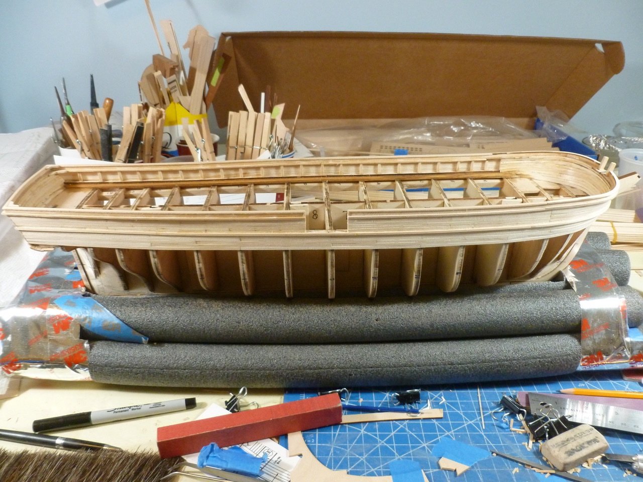
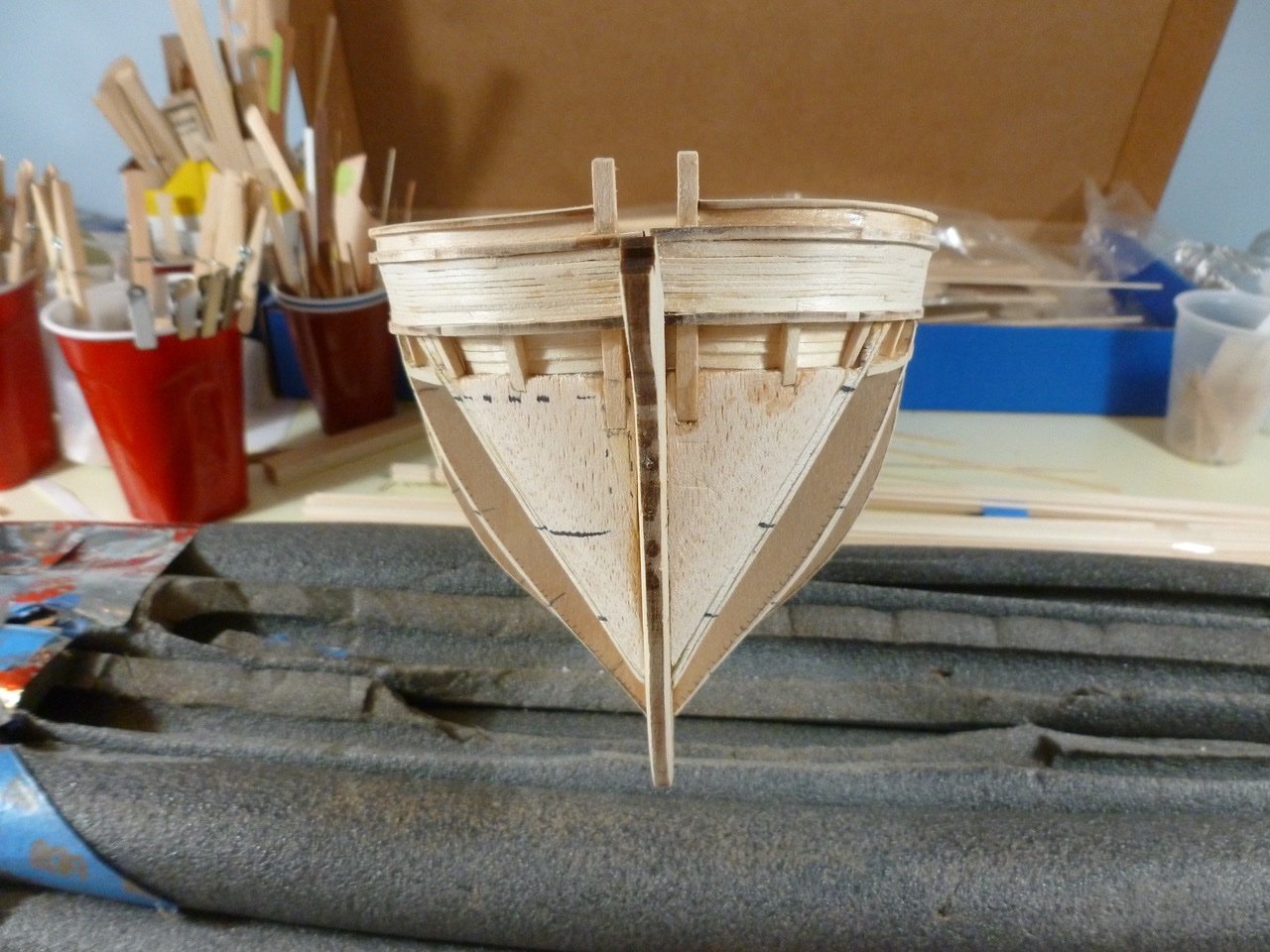
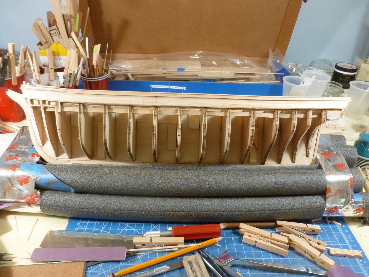
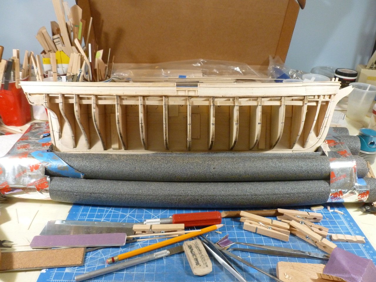
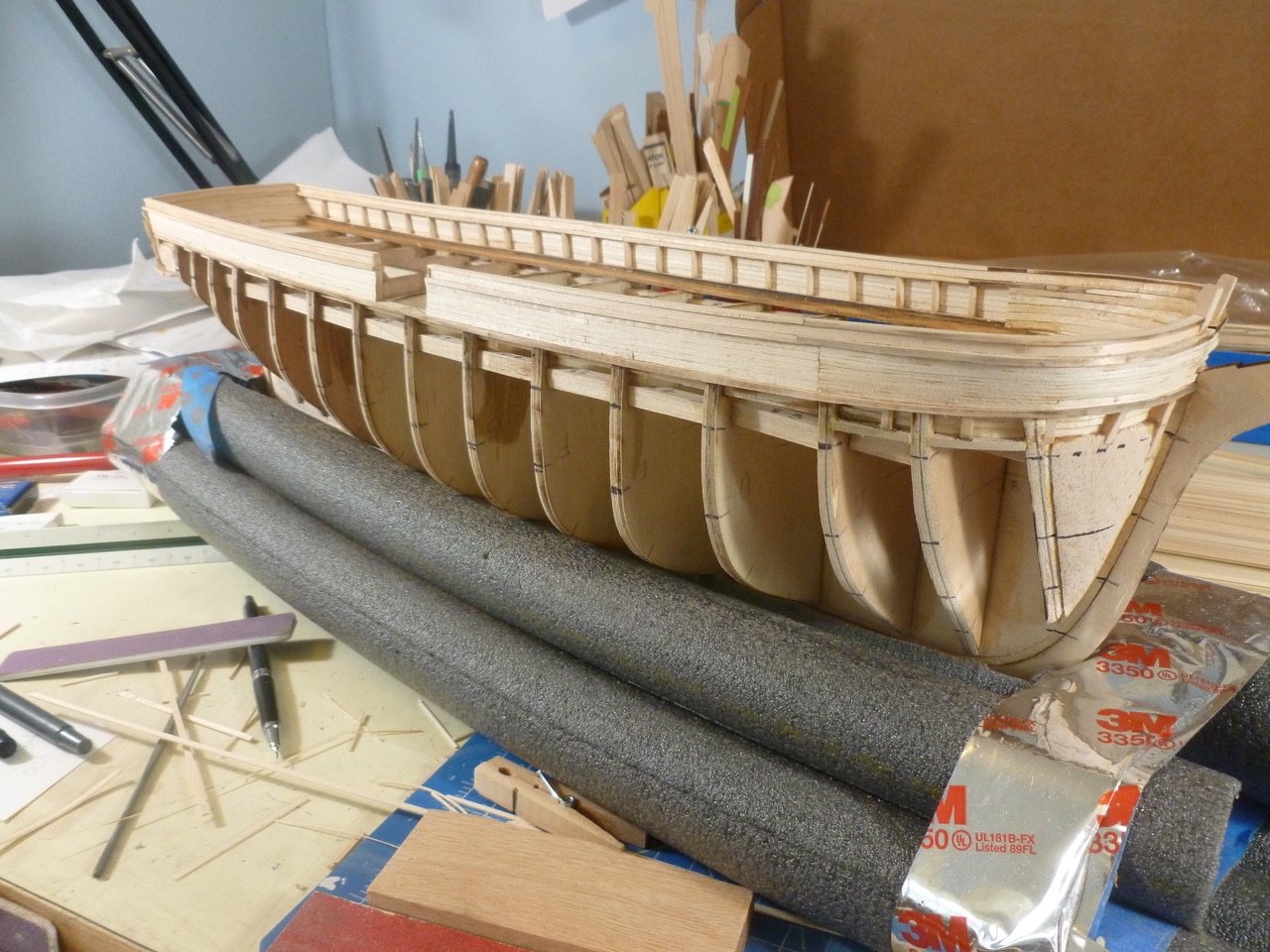
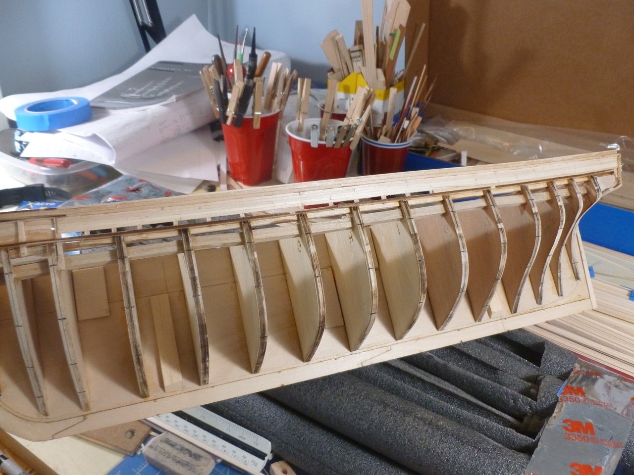
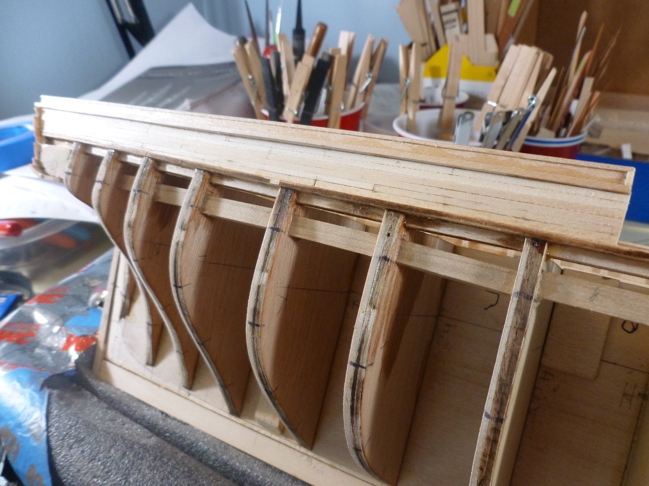
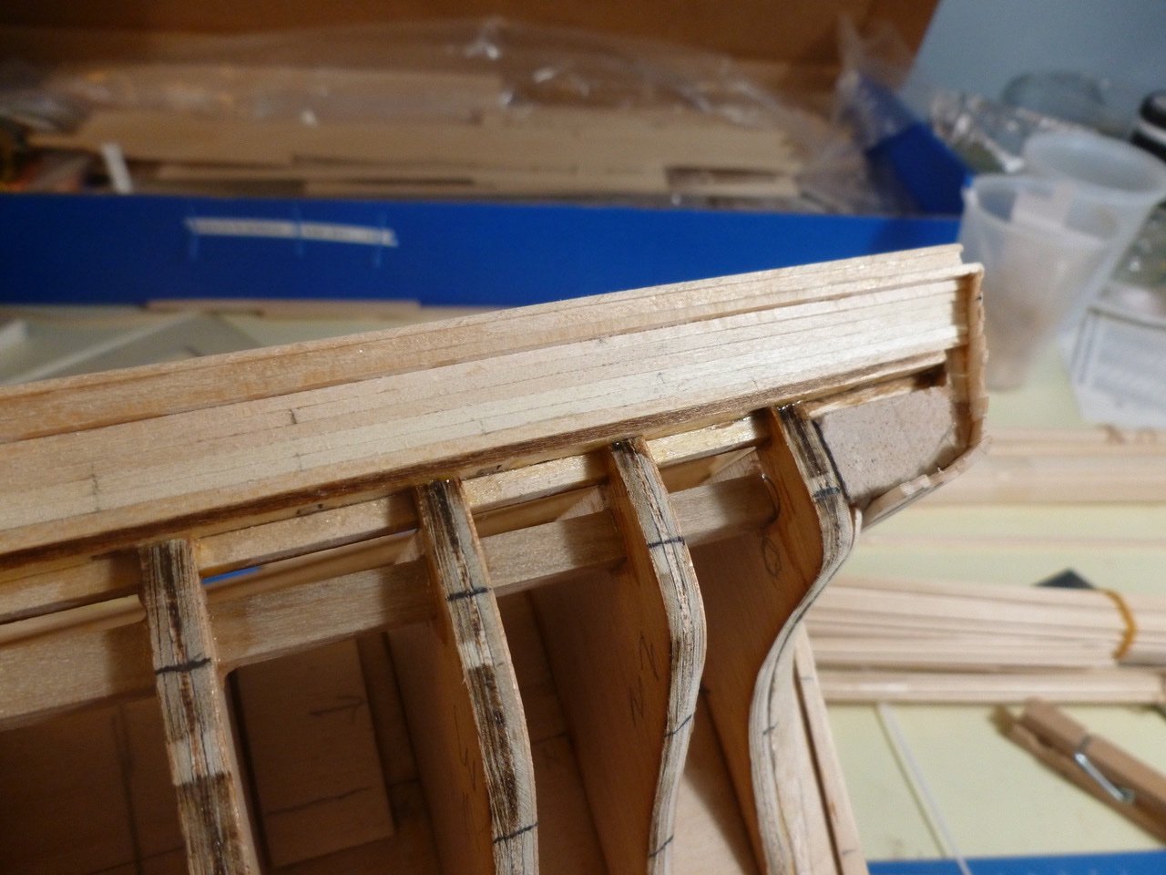
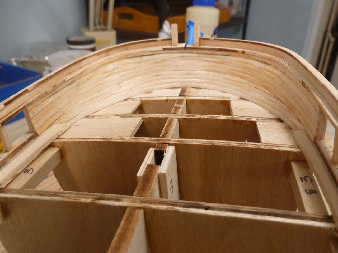
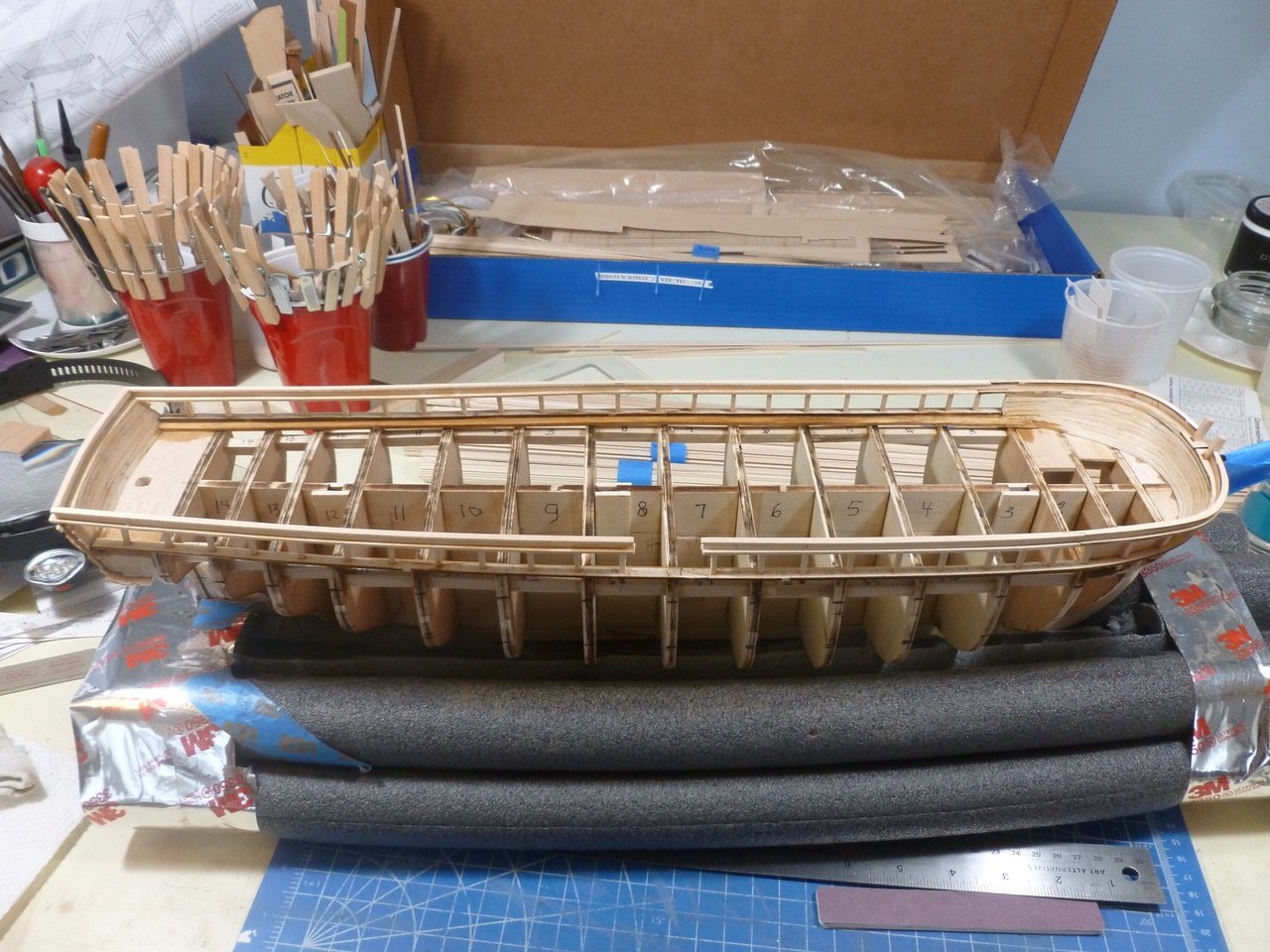
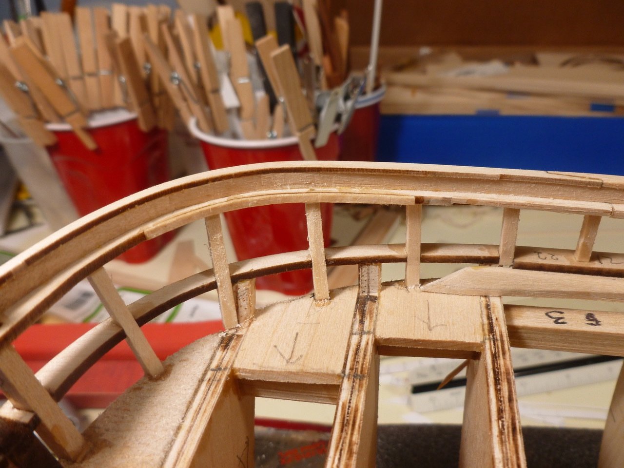
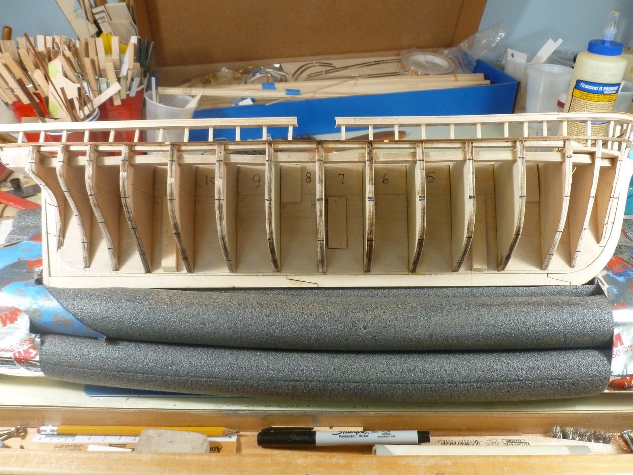
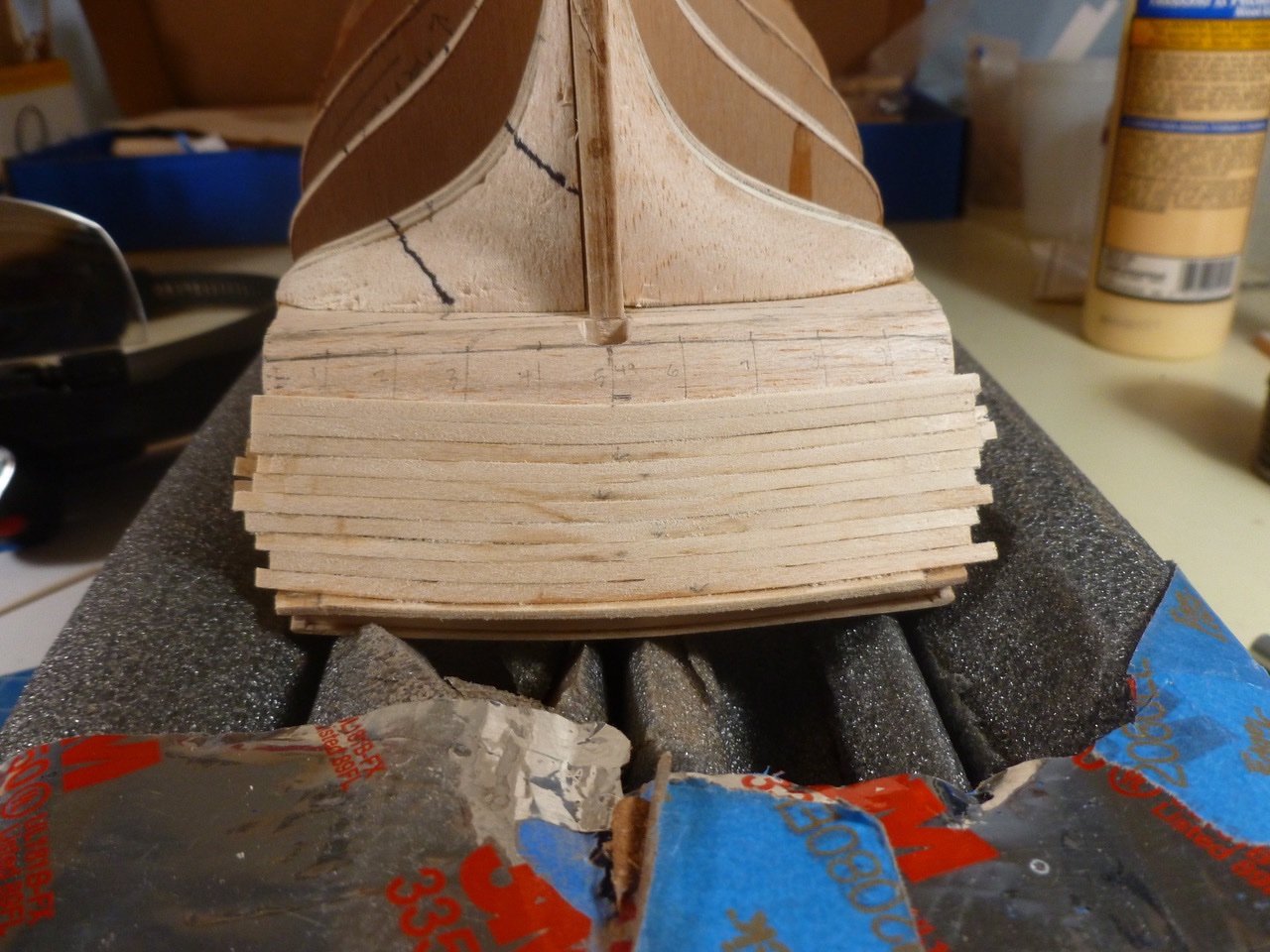
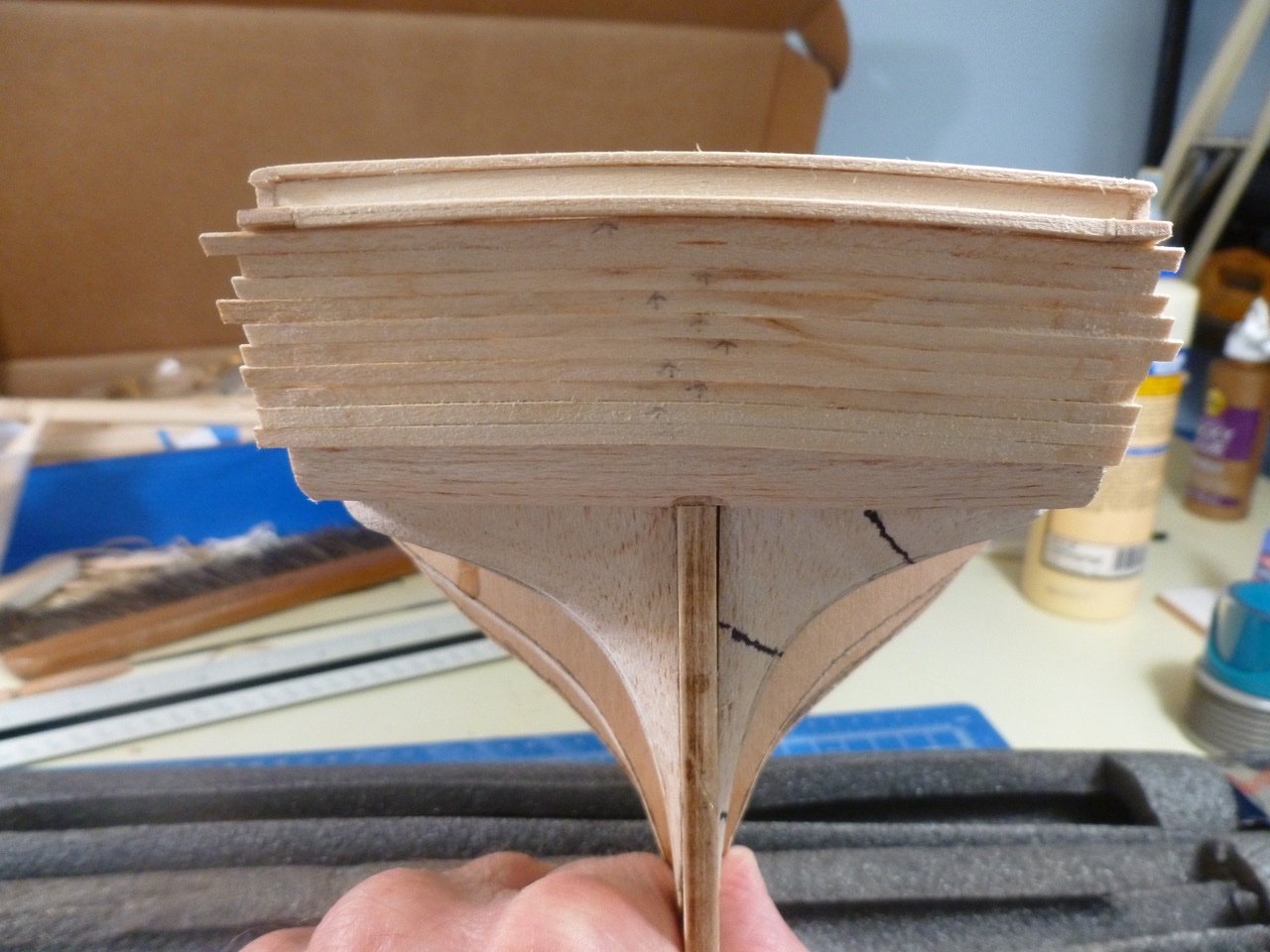
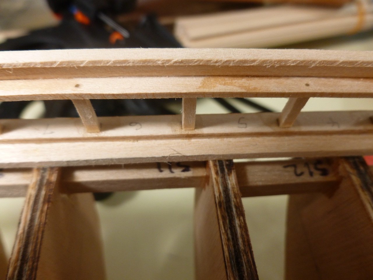
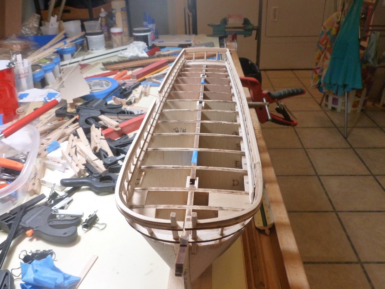
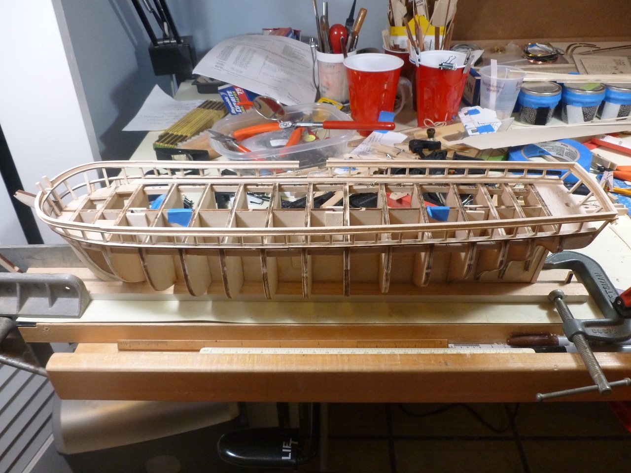
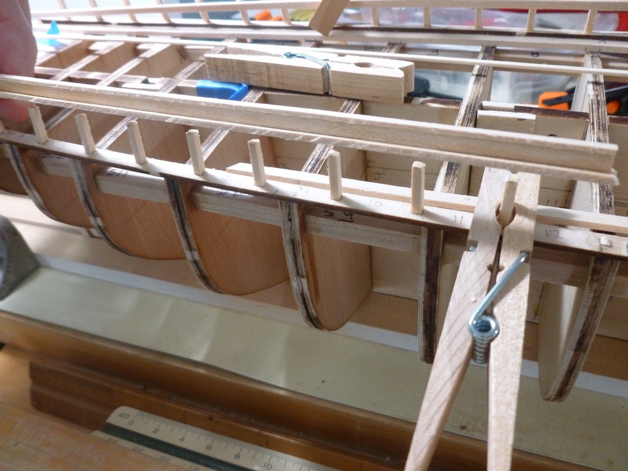
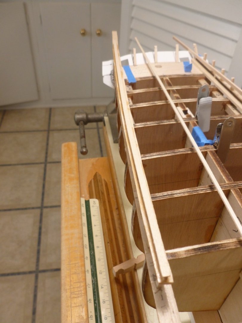
To those who dropped in or gave likes, thank you for your interest and support. Planking is proceeding at a leisurely pace, a cross between watching grass grow and the old Three Stooges bit (“slowly I turned, step by step…”). I’ve been letting damp, twisted, tapered and bent planks dry on the ship before gluing them in place, and family activities have taken precedence. Actually, sitting through a five hour swim meet to watch 5 minutes of a loved one’s competition is great practice for improving patience. The planking process for me starts with the fore and aft curved pieces followed by the straighter middle planks. Lining off and transferring tick marks help immensely in keeping things orderly. Aft planks have been the most challenging, partly due to compensating for overly aggressive fairing of the last bulkhead. The good news is the bow and stern blocks have proven their value as a place to anchor the plank curves. The planks are going in with a minimum of unwanted dips. My cheap and cheesy pipe foam insulation support, which has been used on previous builds, gives a protective base for working and allows a quick transition of the ship from upright to upside down, either parallel or perpendicular to the foam strips. Just pick the ship up and put it down. I carved out the center section of foam to allow the ship to settle in when upright; the foam has enough flexibility that I can tilt the ship at several angles. I expect to be moving to a more rigid base for deck and rigging. I bought some brass pedestals and a mounting board from Bluejacket. The long screws that came with the pedestals look to be a tight fit widthwise, but workable since I added supplementary blocking at each location. Rubber bands are helpful at awkward clamp angles. I found that stretching the band on one side or the other allows some fine tuning of the clamping force direction. Lift the band, pull one way or the other and set it back down. At the tuck the symmetry is holding pretty well through plank 10 (in the picture plank 9 is marked on each side). Looks like I may need some filler in this area if I can’t even out the clinkering with sanding. I’m trying to keep things aligned at the bow. It’s interesting that the plank upsweep at the stem, which is a function of aligning planks with the tick marks, is more pronounced in a head-on view than in views off axis. As my Dad said years ago whenever I was going through a challenging time, “This too shall pass.” But the funny thing is that I like planking. Go figure. Thanks for viewing. Steve
-
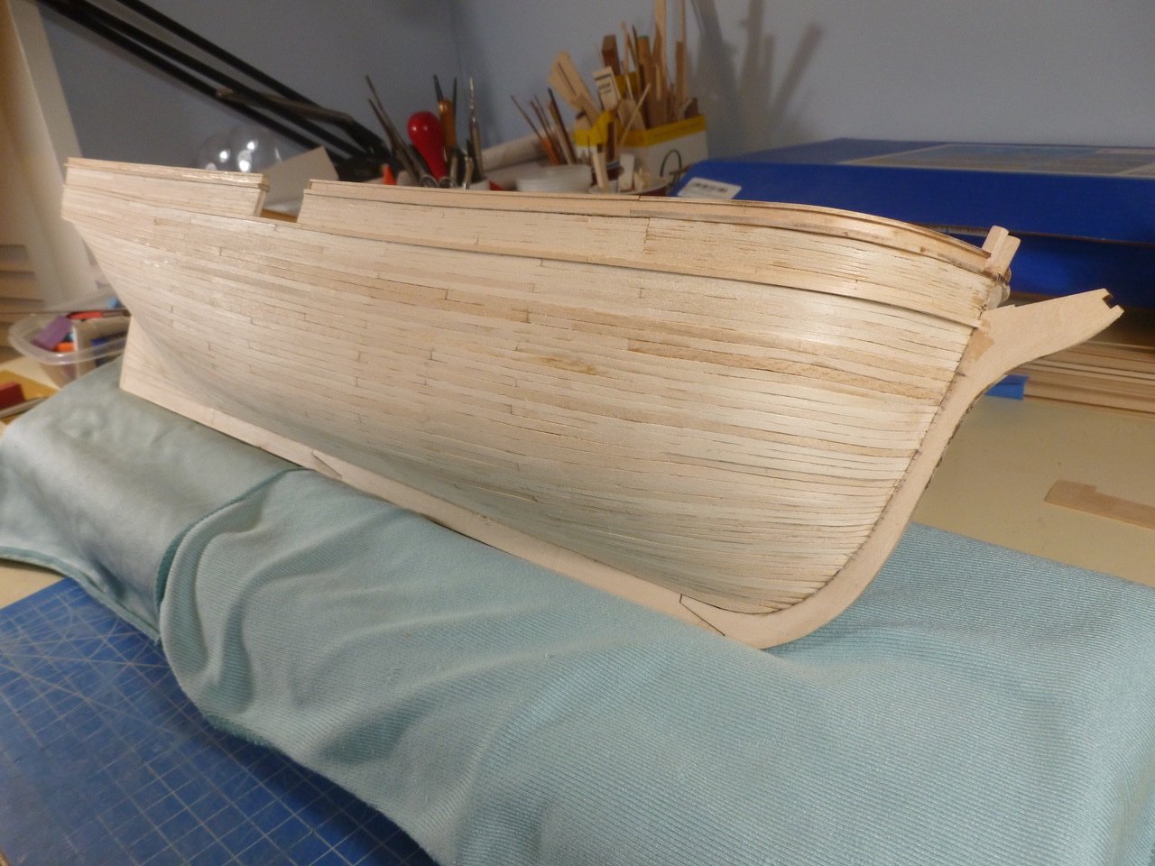
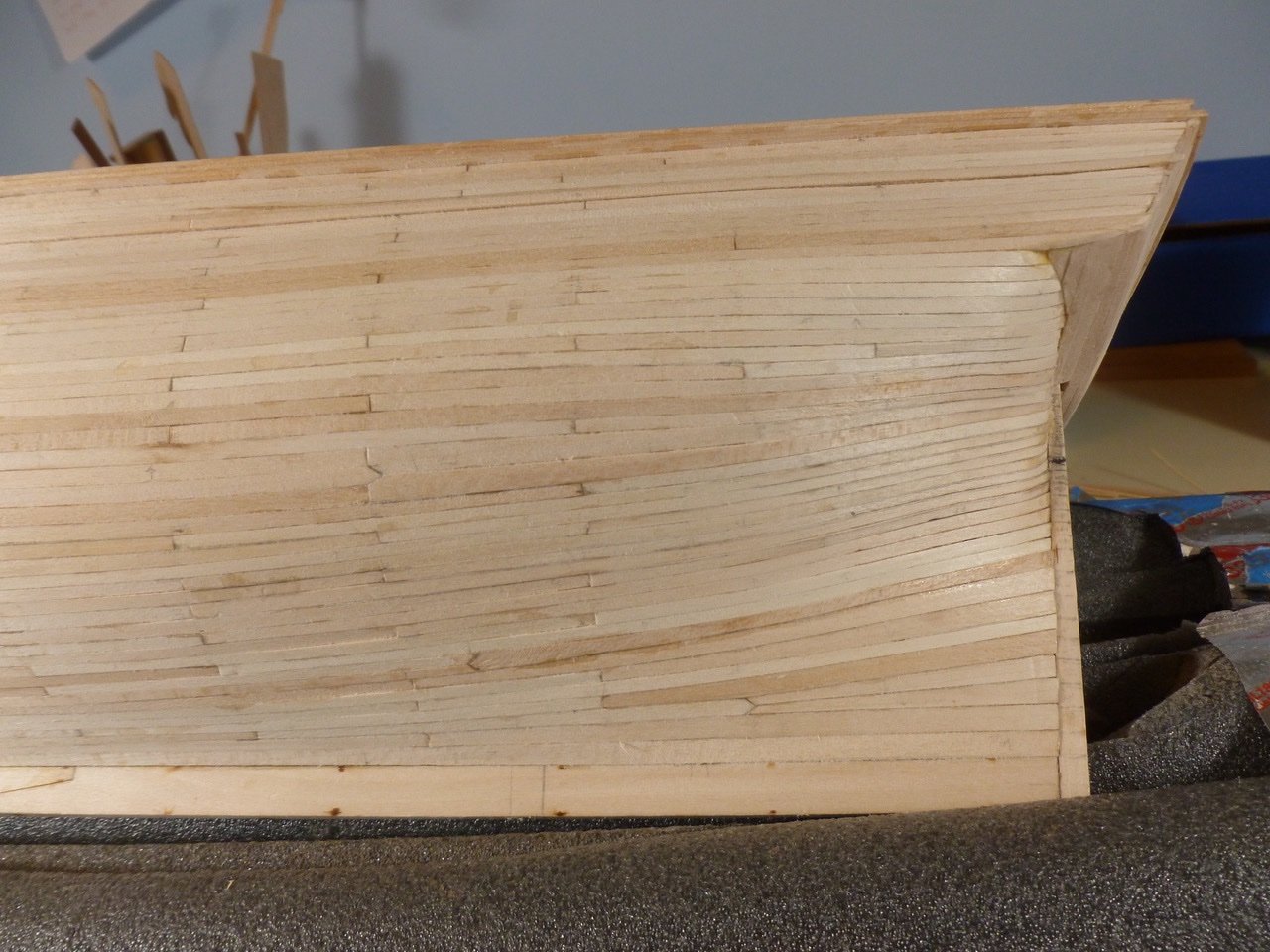
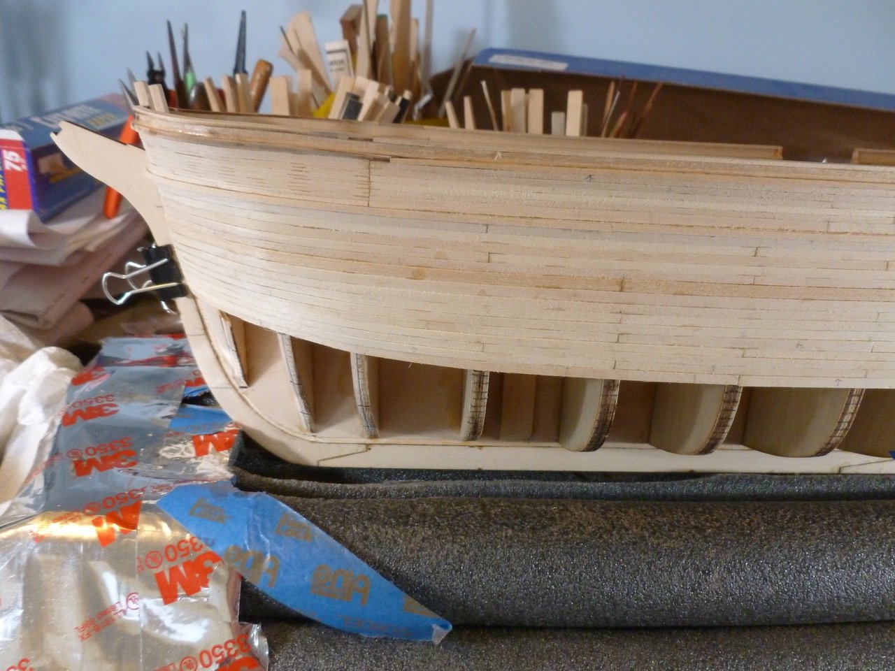
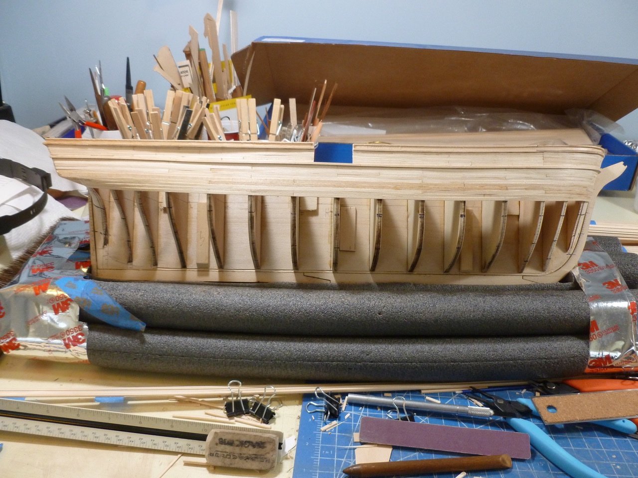
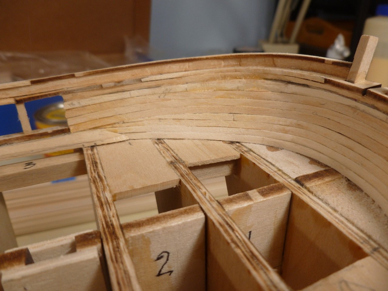
To those who dropped in or gave likes, thank you for your interest and support. Work is ongoing for the A-band planks. The tuck twist has been challenging. It may be the result of my idea of using a rabbet (that’s how I learned to spell it in seventh grade woodshop class) at the counter to capture the plank ends. Or maybe the planks needed a stronger twist. Or maybe I sanded the last bulkhead too much. Whatever the reason I started seeing a gap between the bulkhead and plank. Well, maybe a little shim would help. But it was like a drug. A little shim turned into two, then a fatter one, until I realized it would be a never ending battle with no good outcome. I worked so hard getting the planks bent that it pained me to even think about resorting to the chisel, but chisel I did and stripped off two planks and all but one little shim. I rebuilt the planks, attacking each one with a boiling water dip, the house iron bending station, some hand finessing and a few rubber band/wood strip clamps. Seems to be working better. Bow planking is gradually straightening out as I move down the hull. Lining off bands and individual strakes helps staying in line, and getting back into line when one becomes wayward. Feels like elementary school but it works. Planks are going in pretty tight and reasonably flush against each other. Joints are spaced apart horizontally and vertically, although the plank lengths vary so joints are not necessarily aligned vertically. I don’t know if ships actually used matched length planks or if they used what they had on hand to save cutting off ends. I’m doing the latter in an effort to make good use of wood. Below are a few shots of overall progress. Thanks for viewing. Steve

-
Nic, Thanks for sharing another great job. So full of valuable lessons to help us build our skills. Steve
- 121 replies
-
- 2
-

-
- Newsboy
- Model Shipways
- (and 2 more)
-
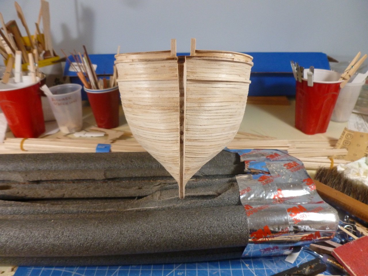
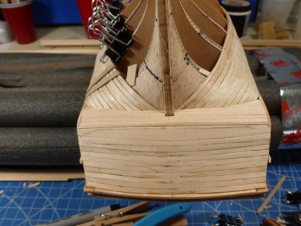
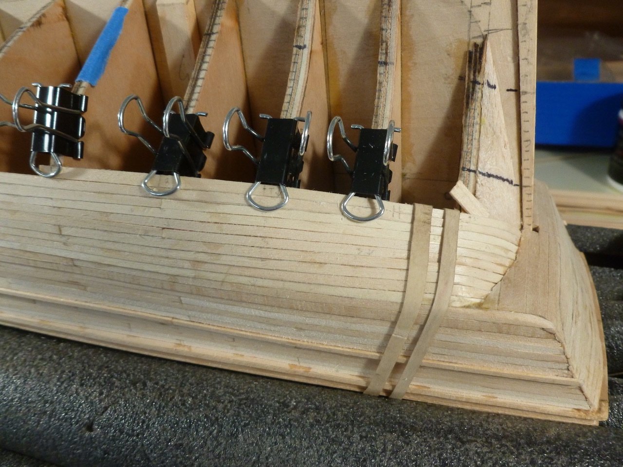
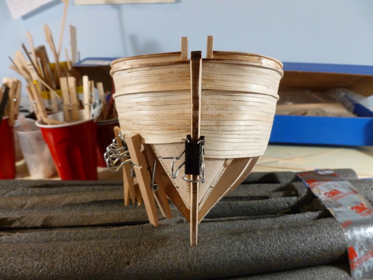
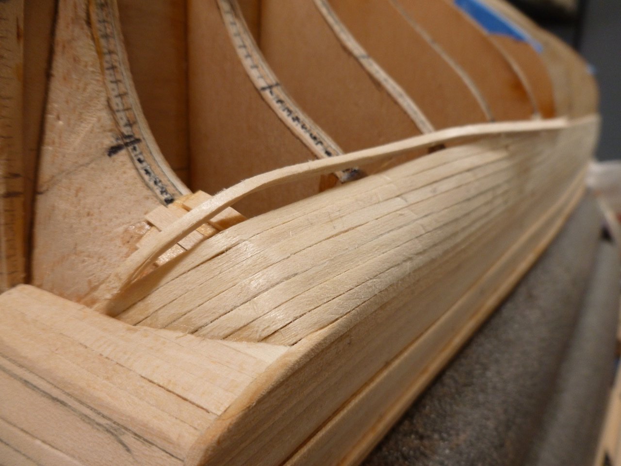
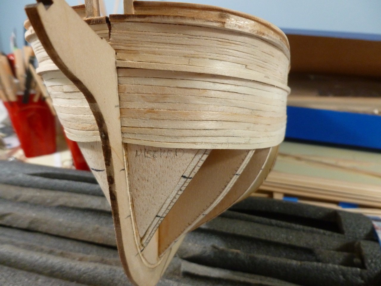
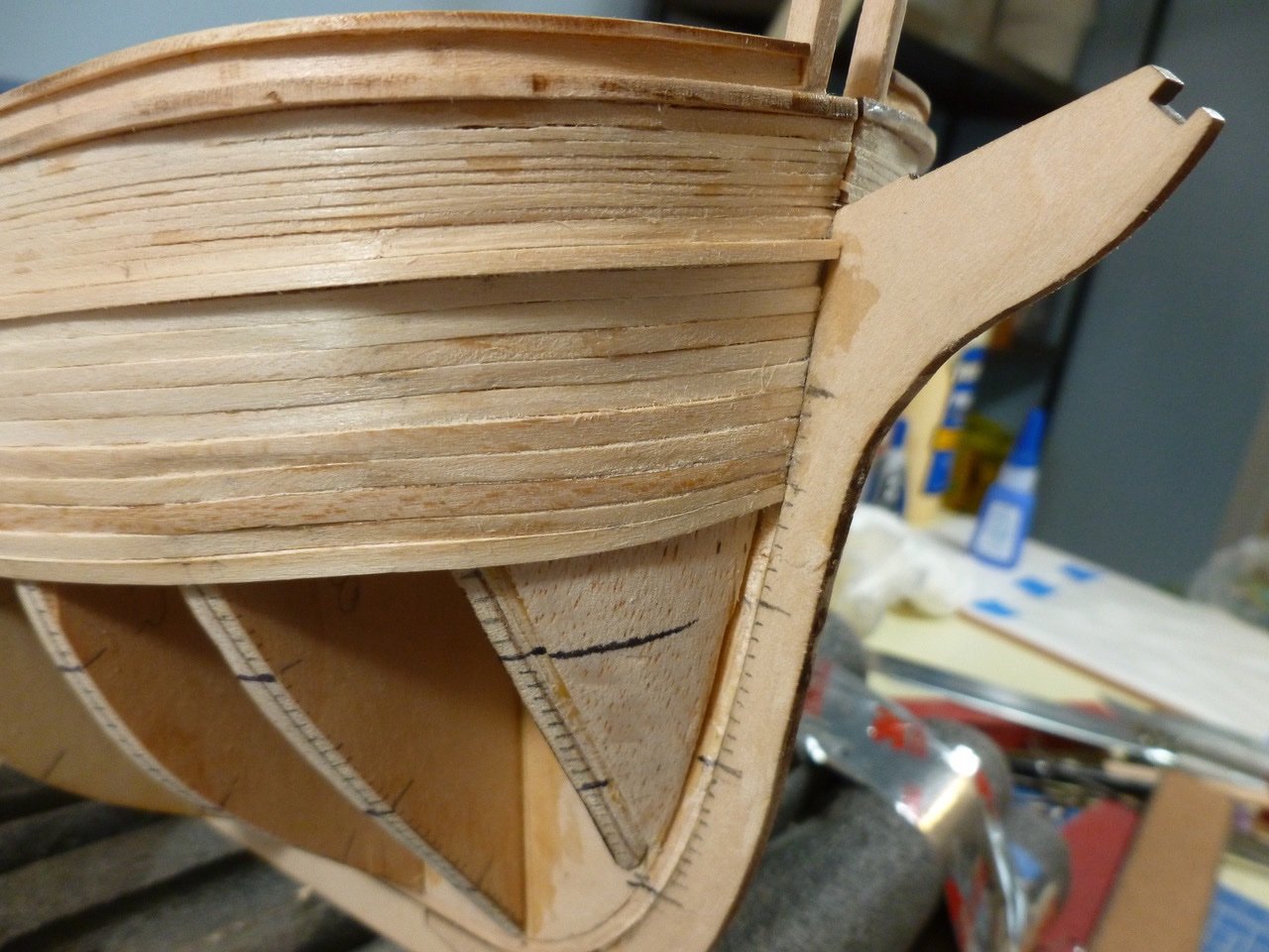
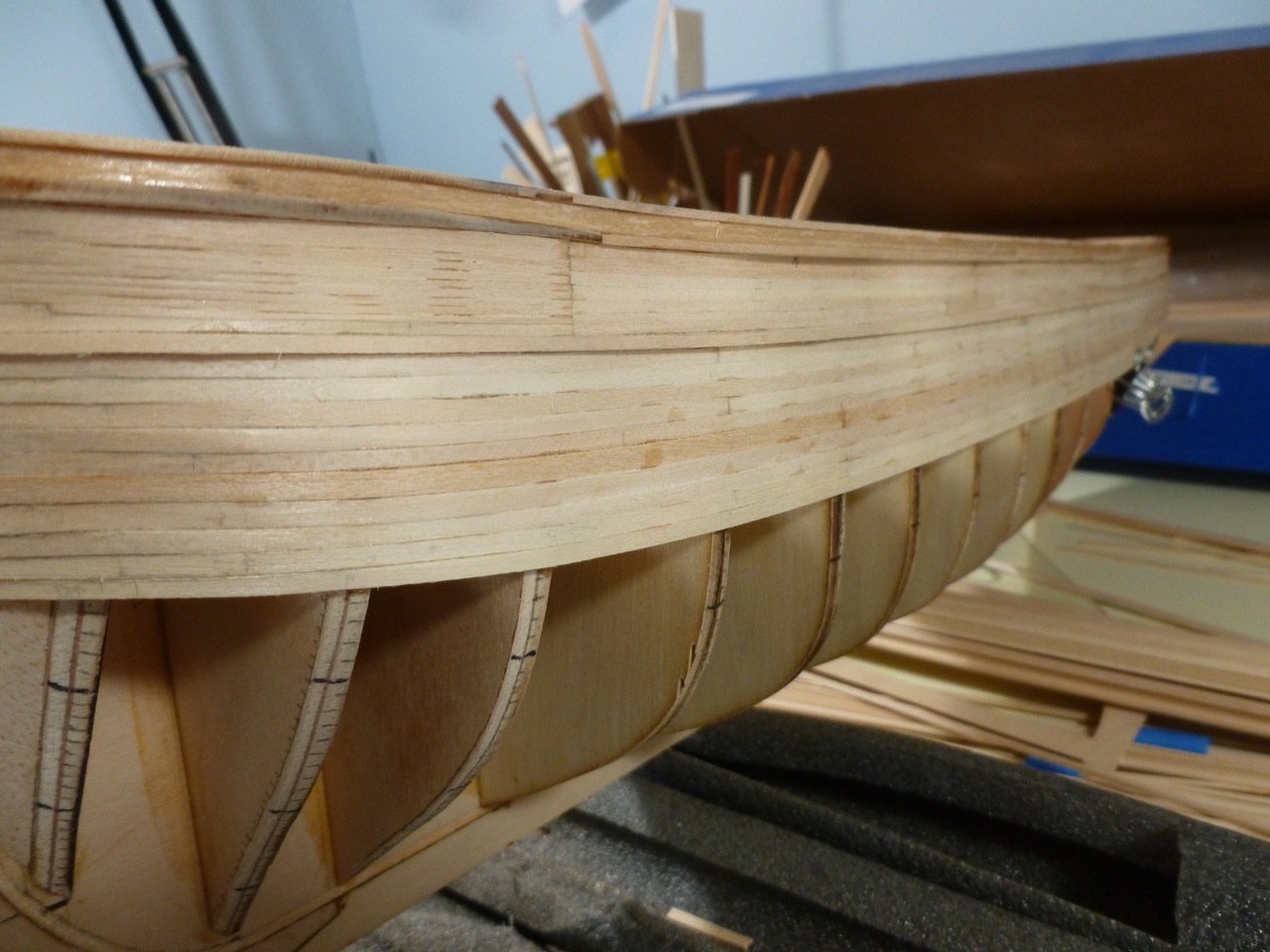
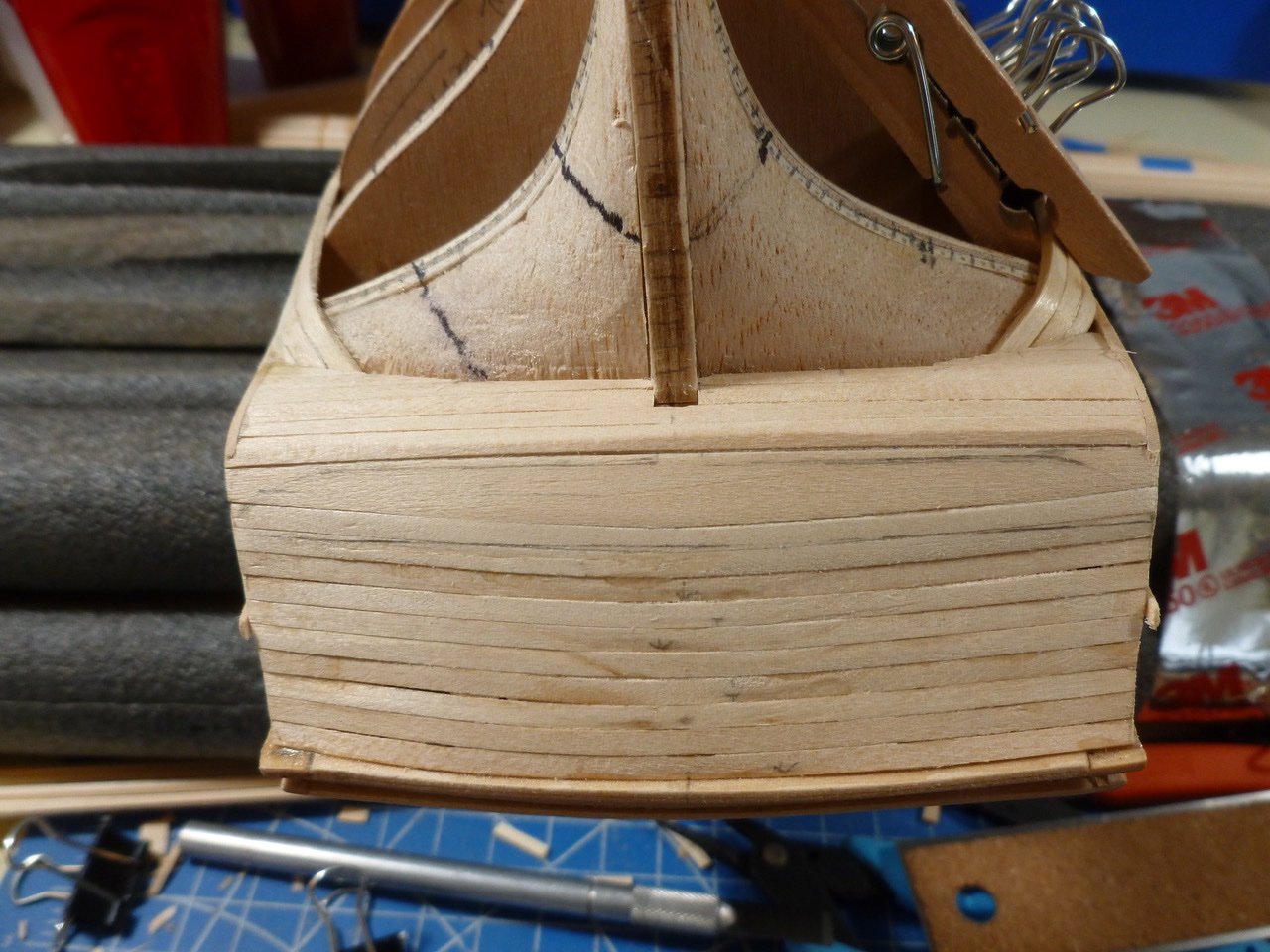
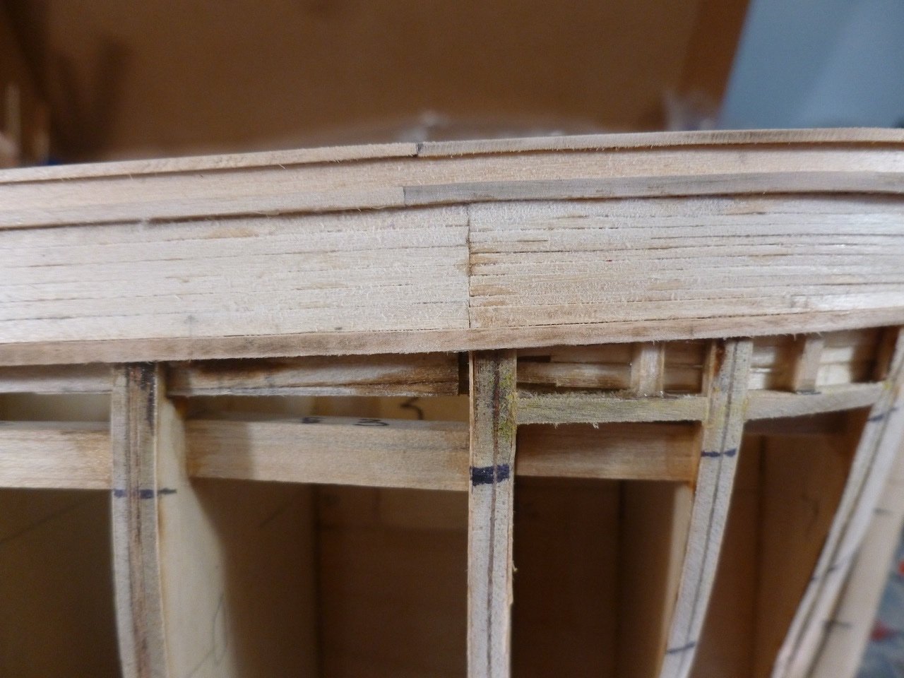
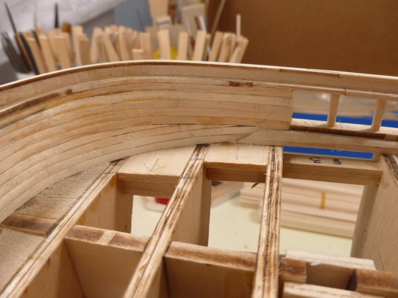
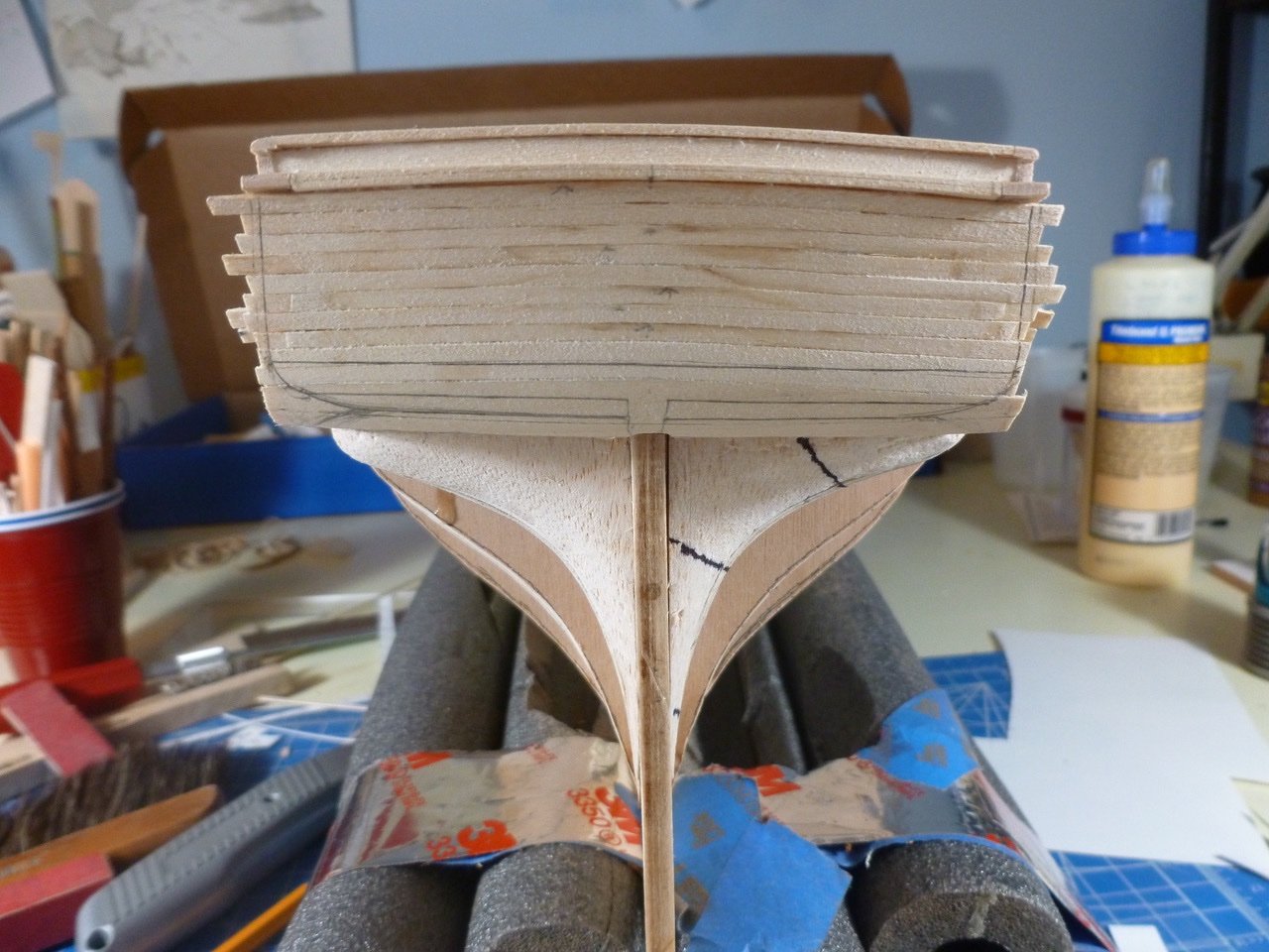
To those who dropped in or gave likes, thank you for your interest and support. Work this period focused on the wale and A-band planks, of which half are now installed. I’m not sure if I was inaccurate in transferring tick strip marks or if the variation in plank widths is leading to some additional tapering within the strakes. It’s not so noticeable (at least to me) in the side views but more so in the bow, especially head-on where I’m trying to keep the planks balanced on either side of the stem. When the bow is viewed from either port or starboard quarter some of the funkiness in tapering seems to go away. A possibility is that the tick marks on the stem may be a bit wonky compared to the marks at bulkheads A and B, but the alignment seemed accurate when I was laying out the bands so who knows. Bring on the flat black paint. Another challenge is the plank intersections with the counter. I previously formed a rabbet in the counter, hopefully to better capture the plank ends. It seems to be working so far, after getting past the first plank on each side which was a bugger. I cut and back sanded a plank, then dipped the tuck end into boiling water for a minute or so. After fine tuning with a hot iron and some hand bending I was able to bend and twist the plank in place so I could clamp it while the plank dried. I touched up the installed tuck with a touch of water and the hot iron which helped smooth out the severe curve. The rabbet captures the ends and the tucked planks have reasonable symmetry. If anyone thinks this procedure may run into a roadblock as I work my way across the counter please chime in. I haven’t done a ship with a counter and tucks. Where the first tucked plank takes its initial bend it creates a little triangular gap between the plank and its neighbor. As a trial I filled the first gap with a poultice of sanding dust and carpenter’s glue, schmoozed in place and sanded. One of the planking tutorials showed the a similar gap being filled with a triangular bit of plank but in this case the gap is very small and the poultice helps conform to the space. Once the planking is finished I'll need to install the fashion piece, after I trim the projecting planksheer. I'll also need more sanding at the counter ends to round them up a bit. Oh, and don't look too hard at the aft ends of the two planks that enclose the counter ends. I'm still chasing the original sin of one side of the stern being a sixteenth of an inch higher than the other. Thanks for viewing. Steve
-
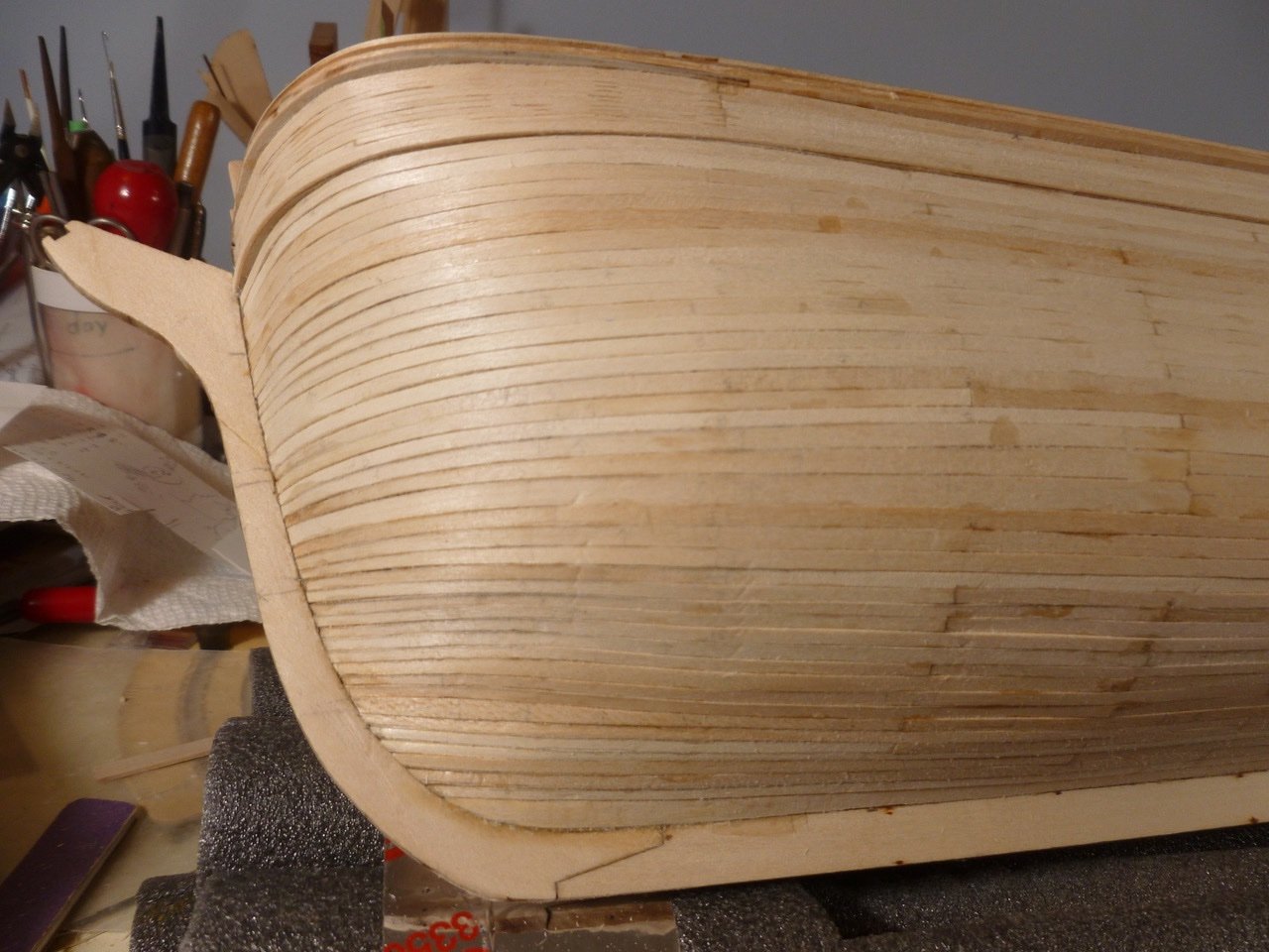
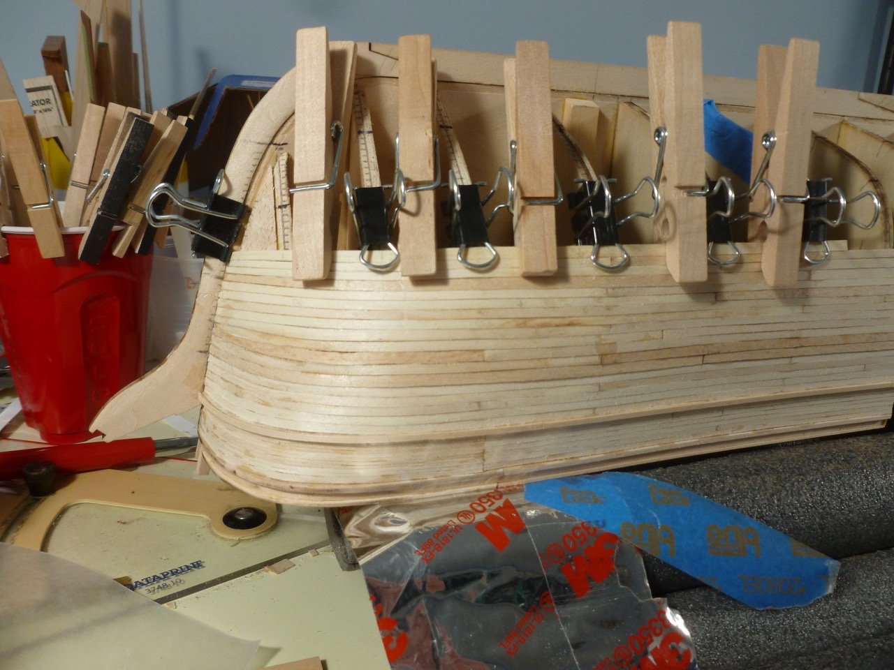
To those who dropped in or gave likes, thank you for your interest and support. A milestone! Planks are hung from planksheer to top of wale. Bow planks have a reasonable alignment port to starboard. The 3/64 x 3/32 inch planks vary a bit in widths. Depending upon my level of alertness I either remembered to check before hanging or didn’t. As noted by others there are no 3/64 planks in the kit narrower than 3/32 inch. Conveniently, and after including plank creep, five planks cover the full height from planksheer to top of wale. Not so conveniently the drawings show seven planks in the same height. The choices were to order up narrower planks (I have no way to mill them), try to cut an even sliver off all the 3/32 inch planks (laughable), or use them as is. Considering that there will be a bunch of stuff partly obscuring these planks, and that they will be finished in flat black which hides a multitude of sins, I chose to use them as is, taking care to fit them as tightly as possible to minimize the joint visibility after painting. Okay, okay, okay, I caved. My goal was to maintain the planksheer projection beyond the adjacent planks without resorting to a covering strip. But as others have noted this requires a level of planking perfection, both in materials and installation, that is somewhat unachievable. Turned out I am no different. While most of the planksheer held proud, most is not enough, so I sanded it back and added a covering strip of 1/32 x 1/16 inch. Taking a planking break, I worked on the main rail and topgallant knees. I saw this as a warmup opportunity for all the microscopic deck goodies. I glued a copy of the plan to a piece of Bristol board and used that as a template on a piece of scrap material. Then I descended into that tiny, magnifier-dominated world so comforting to all of us, for a relaxing round of cutting, filing and sanding. The instructions said the knees could be omitted since they will be covered by later construction but it was fun to see them in place. Can’t wait for the thrill of fabricating the really small stuff. Thanks for viewing. Steve
-
To those who dropped in or gave likes, thank you for your interest and support. The bulwark bow skinny planks on the port side went a good bit quicker thanks to the lessons learned on the other side. The port side has a good match with the starboard. The bulwark planking is finished except for final sanding, and trimming the ends of the transom planks (and painting). It looks like I may need a filler to extend the planksheer to the line of the transom(?) Next up is transferring tick strip marks to the bulkheads. I also need to decide how to mount the ship so I can drill for mounting bolts if necessary, before hanging planks. I have already installed some blocking in case that is the final direction. Thanks for viewing. Steve
-
To those who dropped in or gave likes, thank you for your interest and support. I followed up being sick by continuing a cough with a headache, even while we were on holiday for a few weeks. Between that and 90+ deg. F which made the room too hot to work in, not much got accomplished. But this week I revisited the bulwark planking. The starboard bulwark planks are now finished. The port side awaits the bow curve, which is like trying to do a sweeping hairstyle one hair at a time. Being a few 1/32 inch planks short at the bow, as I mentioned in the previous post, I used a wider plank at the top. At the bottom I used a drop plank, which had to be tapered as well as notched and curved. If I were doing the bulwark again I think I’d settle on a common dimension between the plank sheer and main rail, rather than the smorgasbord of heights taken from measuring the drawing side elevation. This might allow easier planking. Or maybe not, if the dimension really changes going forward and aft. Once everything is sanded and painted flat black it looks like the transition between wide and narrow bulwark planks will meet the intent, apart from the meeting line looking like it was drawn while inebriated (sadly it was built fully sober). Hopefully a fine sanding will allow me to dispense with most, if not all filler. Thanks for viewing. Steve
-
To those who dropped in or gave likes, thank you for your interest and support. I’ve been on the sick list but I’m on the mend. In between coughing, headache, no energy and taking giant pills I squeezed in a few tasks. I finished up the tick strips and duplicated the major strakes on the port side. While doing some fairing I thought I’d be smart and use colored pencils to highlight high spots, then had a panic attack thinking the pencils might have wax in the colors which wouldn’t adhere to the plank glue. But all the color came off during sanding, so no harm no foul. I started at starboard aft on the bulwark planks. The instructions call for six planks, one of which needed to be spiled to accommodate a taper, plank creep and some variability between the planksheer and main rail. I haven’t used such narrow planks and the spiling and tapering and creeping are, how shall I say it, most interesting. The bow planks make the bulwark planks look like tree trunks. At least they bend with cold water to allow fast forming around the Bondo can. Since I didn't want to try tapering such a narrow plank I'm combining two different plank widths to come up with the 10 planks called for in the instructions. The port side went much faster and is almost finished. I’m using plank lengths of about thirty feet. Some of what look like extra joints are pencil marks from layout. Thanks for viewing. Steve
-
To those who dropped in or gave likes, thank you for your interest and support. Mike, I expect to try planking without a subfloor, but with some thin balsa sheet between the bulkheads if the planking alone looks too wavy. The waterway, at least mine, has a very small vertical edge where it butts up to the floor planks. If I add a subfloor it will push the deck planks up into the angled part of the waterway, forcing me to bevel all the perimeter plank edges. Seems to me it would be easier and cleaner to add a very small strip around the deck houses as a mini-baseboard, to hide any gaps in the deck to house wall joints. So here it is. A gentleman’s C at best. Tough to bend two ways, have all the stanchions in alignment and (insert other excuses here). The fun part was being able to use my new Dremel detail tool with a floppy sander wheel attachment. Paint will need to hide a lot of sins but there will be plenty of opportunity to see plank joints through the paint. And the ceiling looks a little banged up which may be more in keeping with the real thing. Two more views are below. The port and starboard planks look a bit better than the bow end. Not fond of the knife point planks but the instructions said the thicker strips stop along the planksheer line. Next time (ha ha) I’ll try a better looking drop plank. I think some of that curse will be hidden by the crew head, which is an appropriate mask for it. I put a first coat of stain on the waterway after applying pre-conditioner, which helps to even out the blotchiness in soft wood. May need a second coat to darken it up. An overview of progress. Thanks for viewing. Steve
-
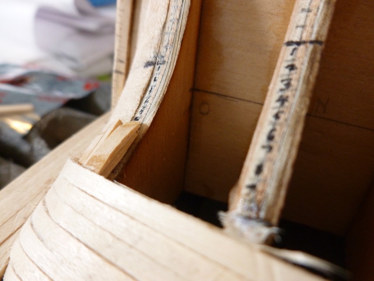
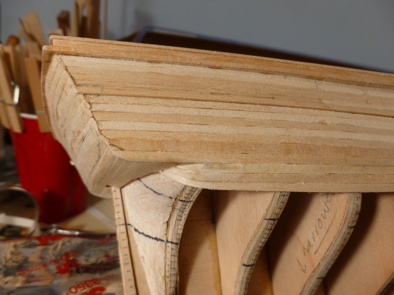
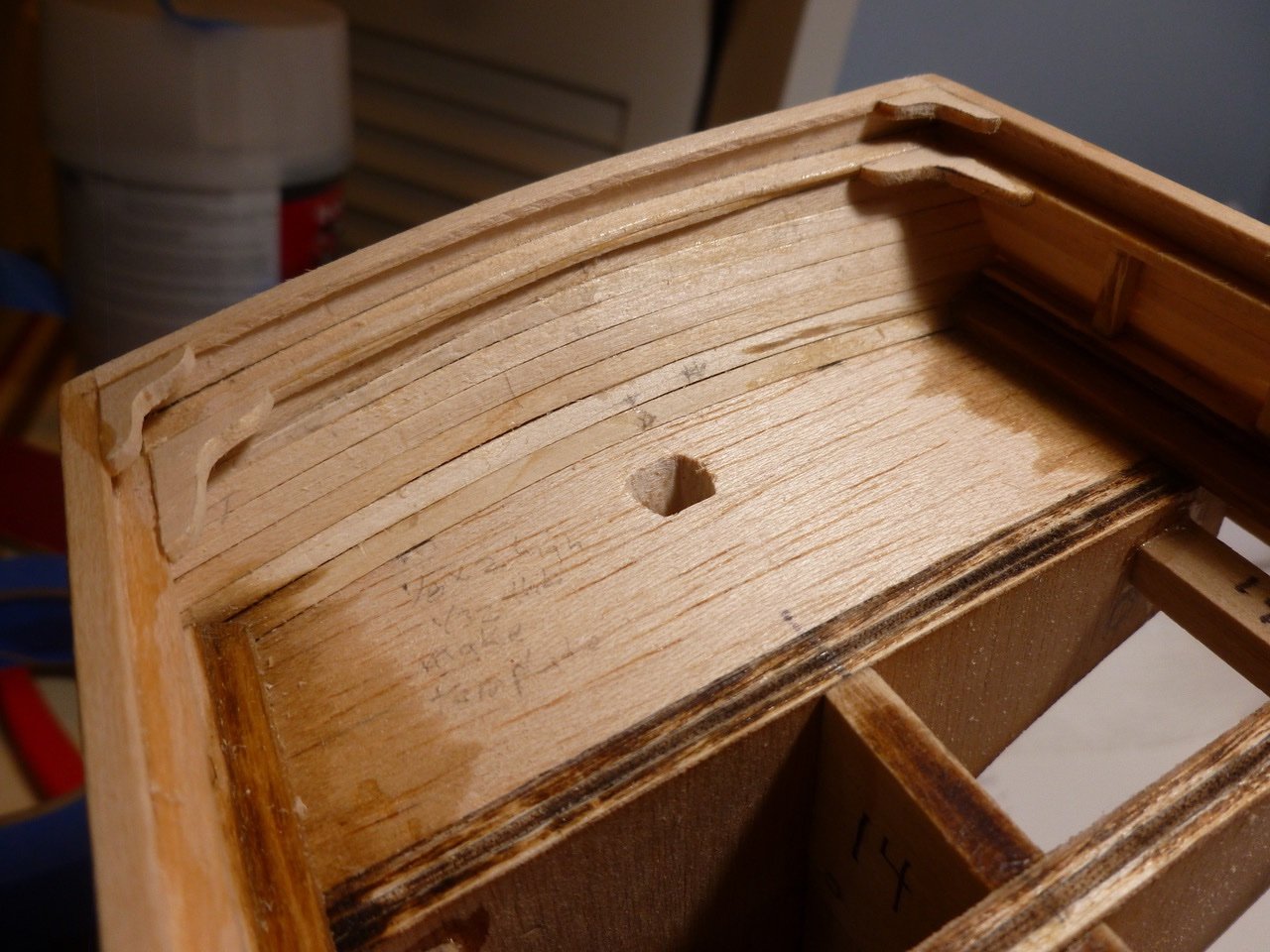
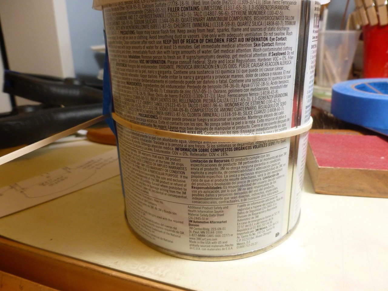
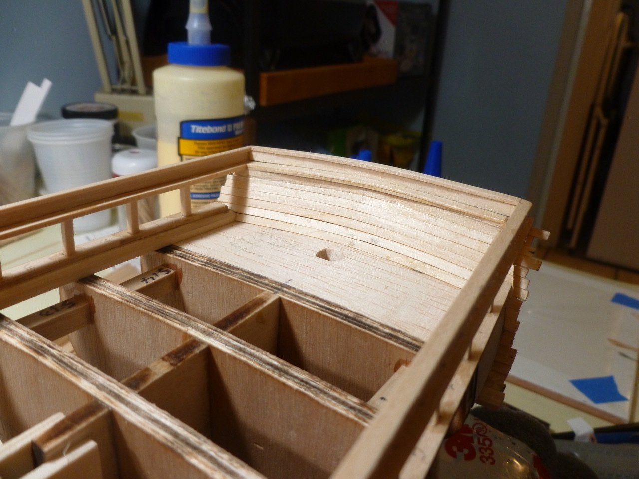
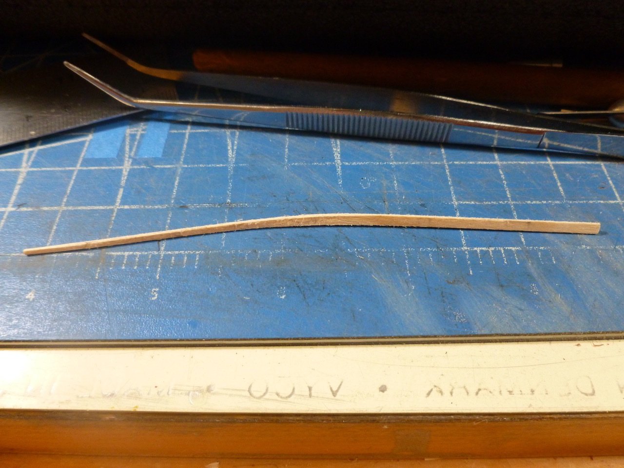
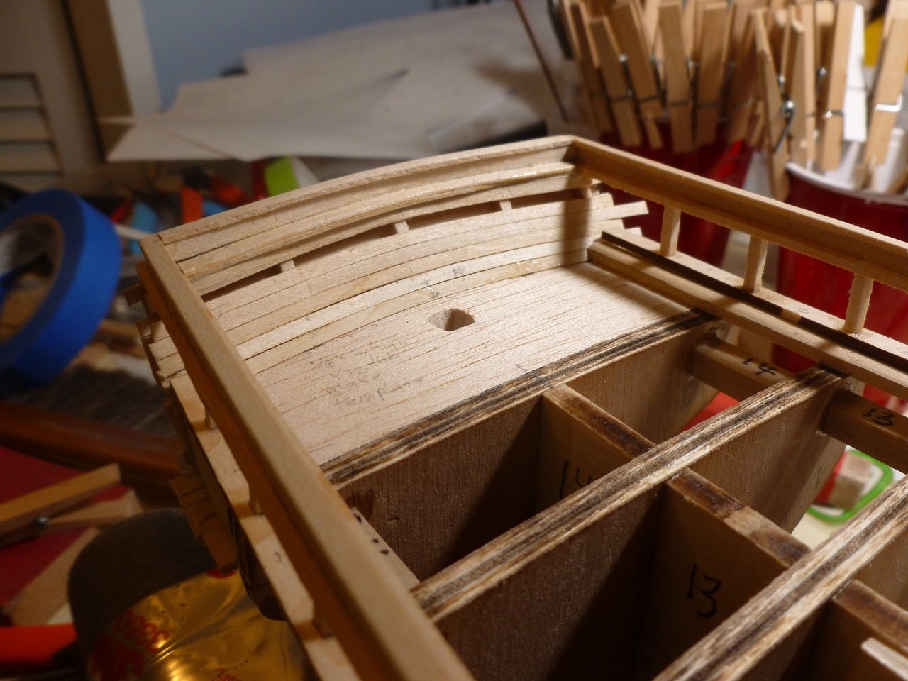
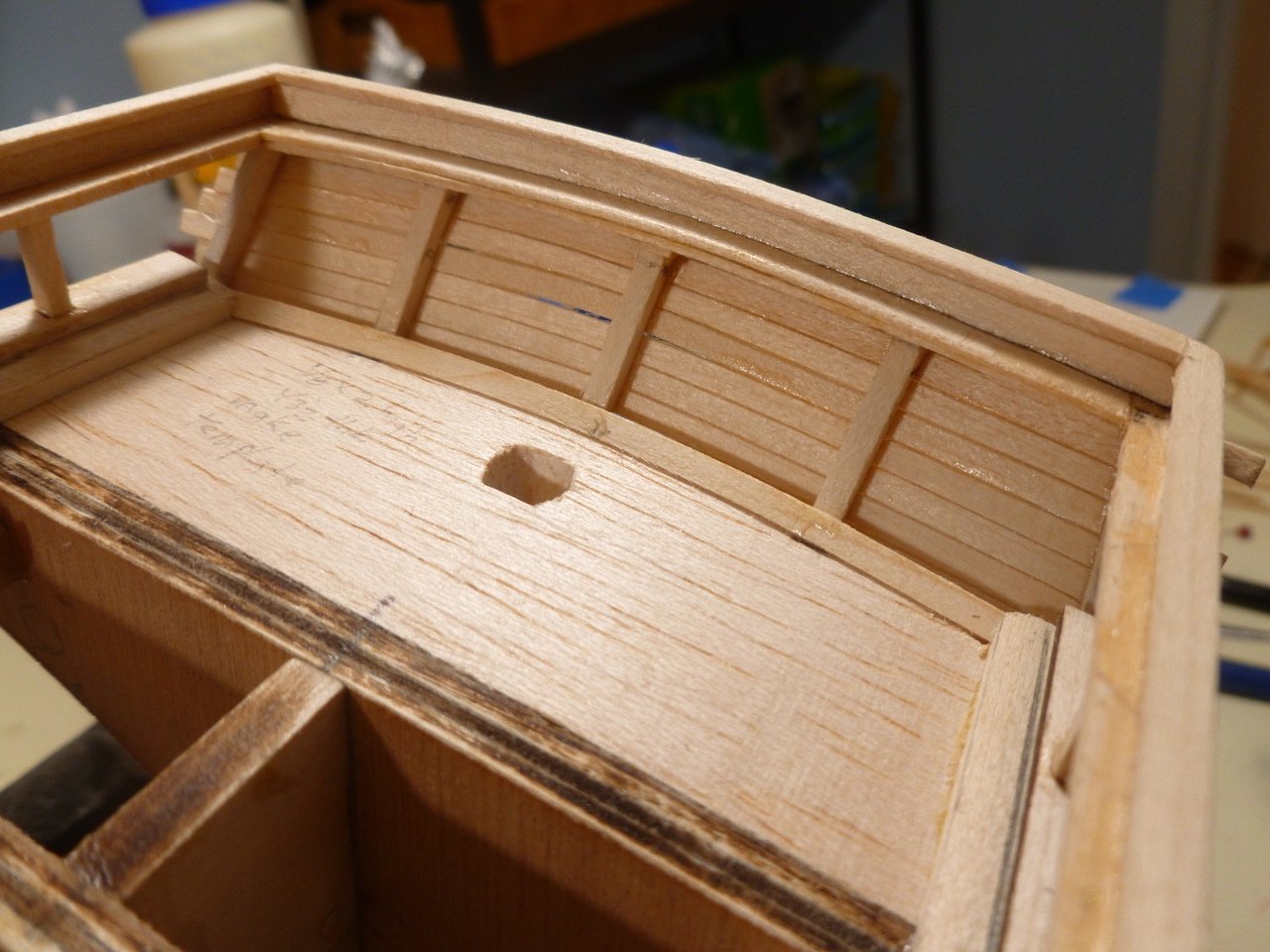
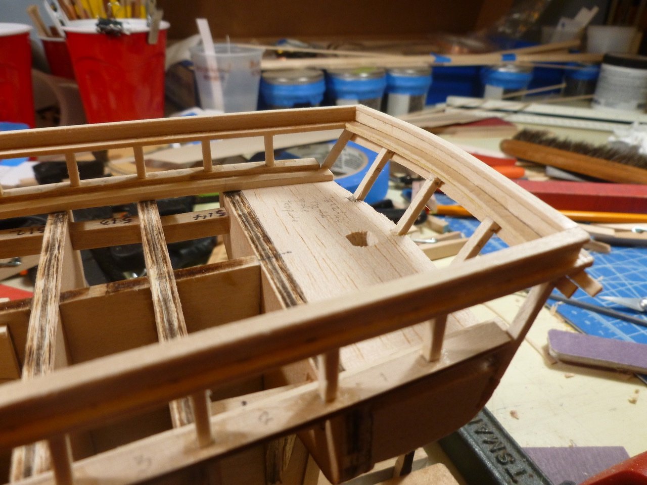
To those who dropped in or gave likes, thank you for your interest and support. JJUSNRET, thank you for your kind feedback. I’m following on the heels of many others who blazed the CWM trail. I hope I can measure up. Mike, thanks for hanging in there. I’m hoping I’ll see more of your build so I can learn from it. I’m not sure I have a decade left so if there’s anything you can do 😇. Regarding the lettering, when I built the Chris Craft barrel back I purchased lettering on a self-adhesive clear backing. I provided a file to the print shop so I could control the typeface. When I did the Zebulon B. Vance (both builds are in MSW) I went to a different shop that had access to an Alps printer, and they made some waterslide decals with white lettering on a clear carrier. I’m not sure if that shop is still around, because their existing storefront was empty the last time I went by. Another possibility is one that I saw in a model railroad magazine, called Circus City Decals (circuscitydecals.com ). I haven’t used them but their web page looks good. Seems reasonable too if you provide artwork. I planked the transom ceiling, leaving an accessible space for a shutter plank (not sure if that term is used for ceilings, but you get the idea). The shutter reflects the slight height difference between port and starboard that I discovered while working on the transom exterior. Guess I’ll be chasing that error for awhile. After numerous test fits the last transom ceiling plank is in place. And I thought the transom ceiling was a challenge. The bow ceiling uses thicker planking up to the planksheer, then thin planks above. And the whole ceiling curves up and out. And it needs to tuck behind the waterway. Then to boot after it’s all finished it will be mostly hidden by the anchor deck. Oh well, it’s a good warmup for the exterior planking. To my horror I realized that despite a good effort the inside edge of the main rail would not be covering a small portion of the bow ceiling planks. I cut shims for each side to provide coverage and sanded them to blend at the ends. A Bondo can has a diameter that approximates the bow ceiling. After wetting and ironing a curve into the plank I lightly taped it around the can. I say lightly because I found that the damp wood surface pulls off very easily if the painter’s tape is pressed down too hard. I also discovered, after almost all the bow ceiling was installed, that I could have pushed up in the middle of the plank while it was “on the can”, so to speak, to make it a better fit for the rising bow. I suppose a side benefit is the Bondo will be readily available if the bow ceiling is too clinkerly. I did some preliminary sanding without remembering the ceiling thickness change so the thickness difference (1/64 inch) may go the way of clinker edges. Sure am glad it will be hidden. As on the transom I planned for a bow ceiling shutter plank. This is a work in progress and the photo shows the plank clamped and drying in roughly the correct location. The plank needed a bunch of spiling and at the wide point it needed to be wider than the typical 3/32 inch bow plank width. But not much wider. I probably should have made two spiled planks but I didn’t. I edge glued a 1/32 thick plank to a thin strip (1/32 x 1/16). But then I realized the spiled two piece plank still needed to be formed, which would require heating. The question was whether the CA glue would stand up to steam generated by wetting the plank and heating it with the clothes iron. A web search indicated the CA might fail when subjected to a steam bath. If it did it would probably deposit CA residue on the bottom of the iron. Not a fork in the road I wanted to take. Given that the plank was small I thought I might get away with a hot tap water soak followed by a quick trip to the Bondo former. It worked, and with a very short soak at that. We’ll see how it turns out. Thanks for viewing. Steve
-
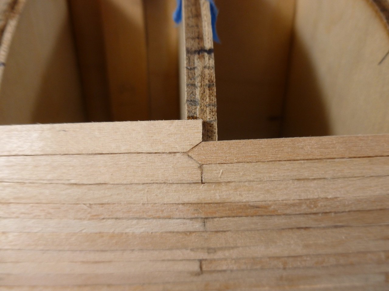
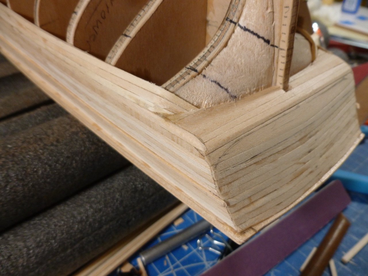
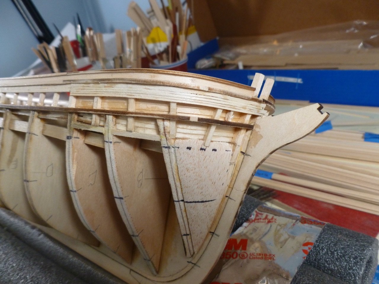
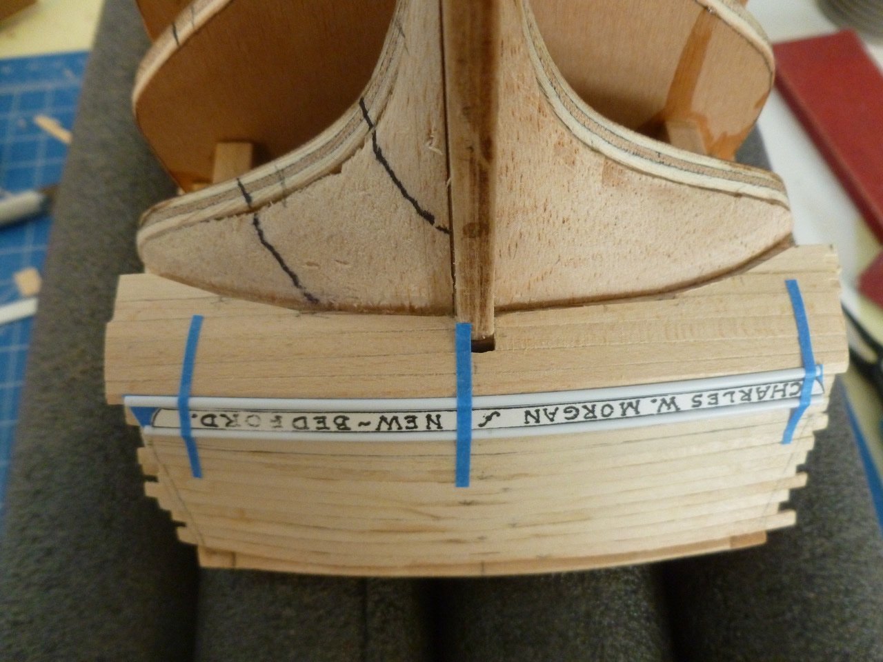
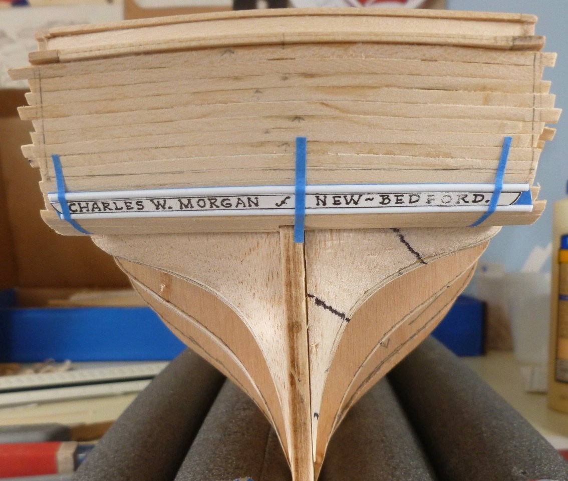
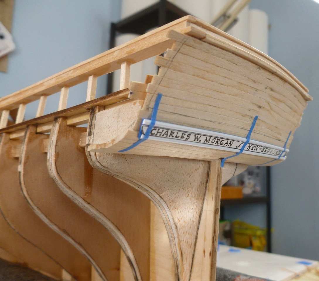
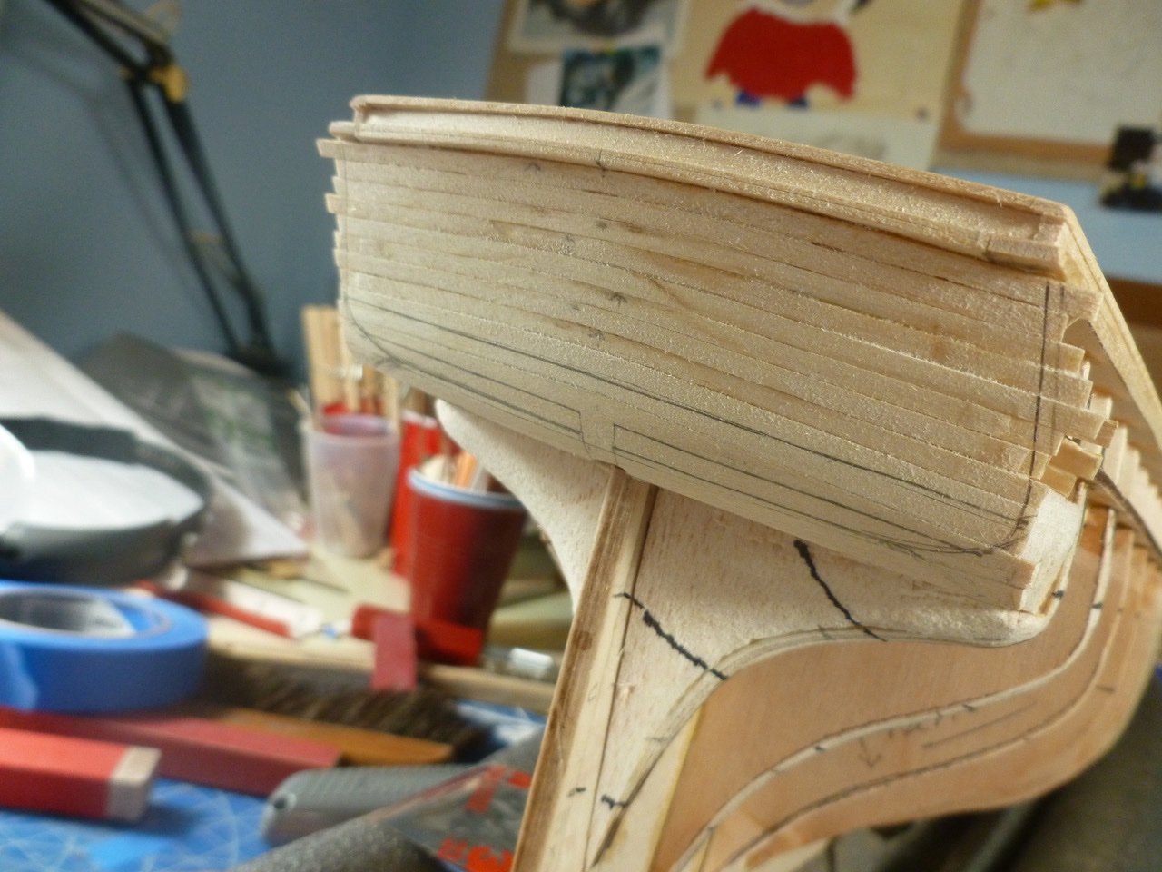
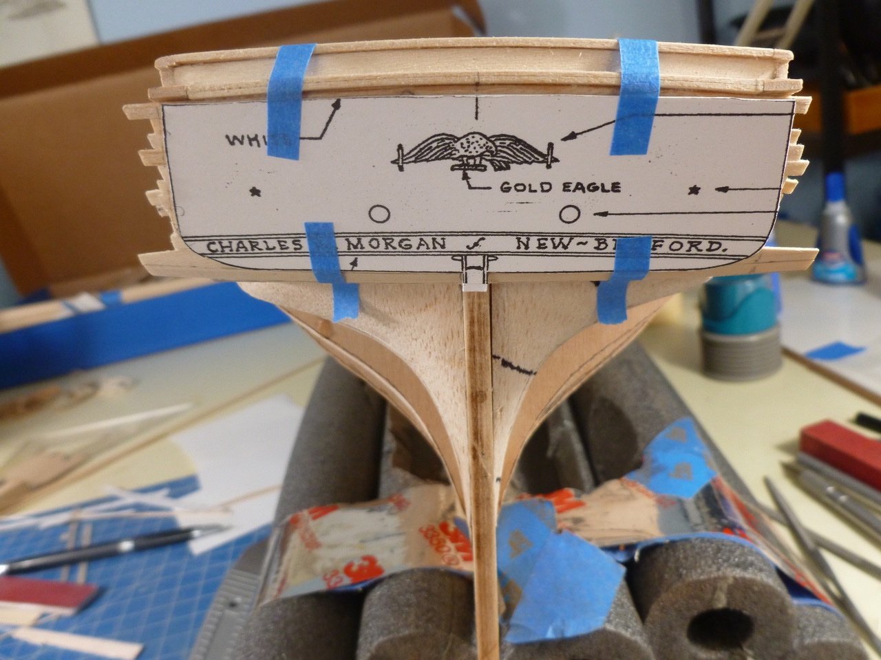
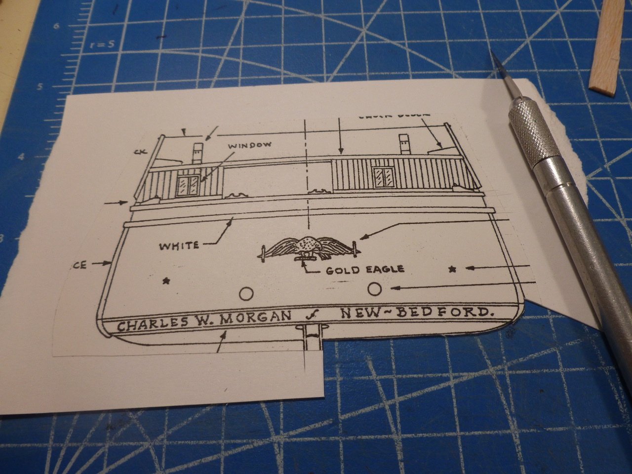
To those who dropped in or gave likes, thank you for your interest and support. Landlubber Mike, thanks for posting the great pics of the Morgan transom and counter. They are most helpful, and will continue to be as I get near the curved tuck at the port and starboard ends of the counter. Still not quite sure how that will work but maybe it will become more obvious once the planking starts to meet the counter and transom ends. Based on the photos I adjusted the positioning of the mockup name plate, and the aft end of the counter, trying to place the name closer to the break line between counter and transom. The moldings are some half round plastic strips that look workable although maybe a bit large (?). The mockup name is a copy from the drawings. I created a rabbet along the joint between the counter and the stern support blocks, hopefully to hide and support the severely curved plank ends. Thanks for viewing. Steve
-
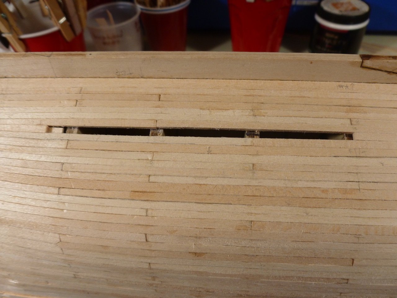
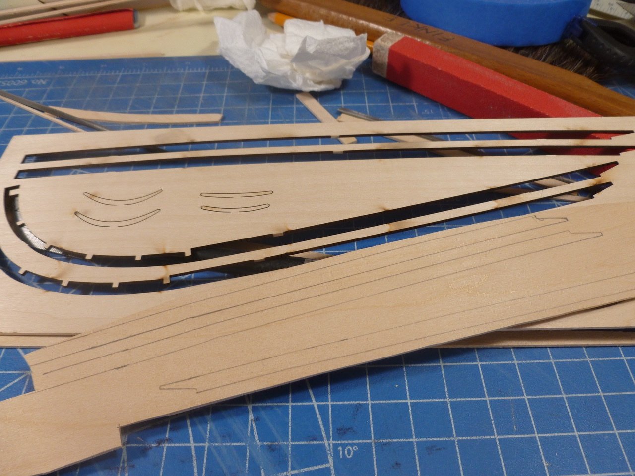
To those who dropped in or gave likes, thank you for your interest and support. I took a break from construction to work on lining off. I started with some black pinstriping tape I had from several models ago but quickly realized it had lost its stickiness, so I switched to the leftover chrome pinstriping tape (la-de-da) I used on the Chris Craft model. Lining off in bands was new to me and it was interesting to see how small adjustments improve the flow of the line while preserving plank width. The tick strips showed that virtually all planks need to be slightly less than the standard 1/8” plank width, when following the plank count per band shown in the drawings. It got me wondering if there is a way to mix and match full size and undersize planks on one tick strip. It would be nice to minimize the number of tapered planks to improve work flow. I'm not sure how that would be done on a planking fan. More thinking needed. Once I had the starboard side plank layout roughed out I shifted to planking the transom, to stiffen it up and to prepare it for joining with the side planking. I steam ironed and placed a few exterior planks and then shifted to the transom ceiling. At this point I realized it would have been better to trim the overhanging ends of the planksheer before other things got in the way. While making some mini tick strips for the transom ceiling I noticed that one end of the ceiling was slightly higher than the other, which appears to be the result of the port main rail being a bit higher than the starboard. Not a big deal for the ceiling since it will all be hidden by other construction, but potentially a problem at the external planks, most of which had already been installed. I also noticed a little daylight peaking through an external plank joint. Some Titebond glue mixed with sawdust, pressed into the joint and sanded smooth should restore darkness. Sure enough there was a height difference between the port and starboard ends of the planks. If carried down to the counter the result would be a noticeable taper at one end only. Then it occurred to me that a wider spiled plank might hide the error, especially since the spiled area will fall within the Morgan nameplate. I split the spiled plank in two parts, hopefully to look more like real planks. When everything is painted black, then covered with letters and white moldings, it probably won’t matter but I’ll feel better about it. With the spiled plank installed I cut a transom template using a copy from the drawings. I traced the template onto the transom. Once I had the full template perimeter I trimmed the template up to the bottom of the nameplate molding, traced again, then repeated after trimming to the top of the molding. This gave me the location of the nameplate and moldings. The finished layout looks workable, and as hoped the off kilter plank joint will be hidden within the name. The counter is supposed to have a double curve at each lower corner where it meets the transom. So far I haven’t found any pictures that show the detail. In the ones I have seen the detail is lost in the flat black finish. I’m also wondering if I should plank the counter now or wait until the hull planks are in place so the counter can hide the severely bent ends. Thanks for viewing. Steve
-
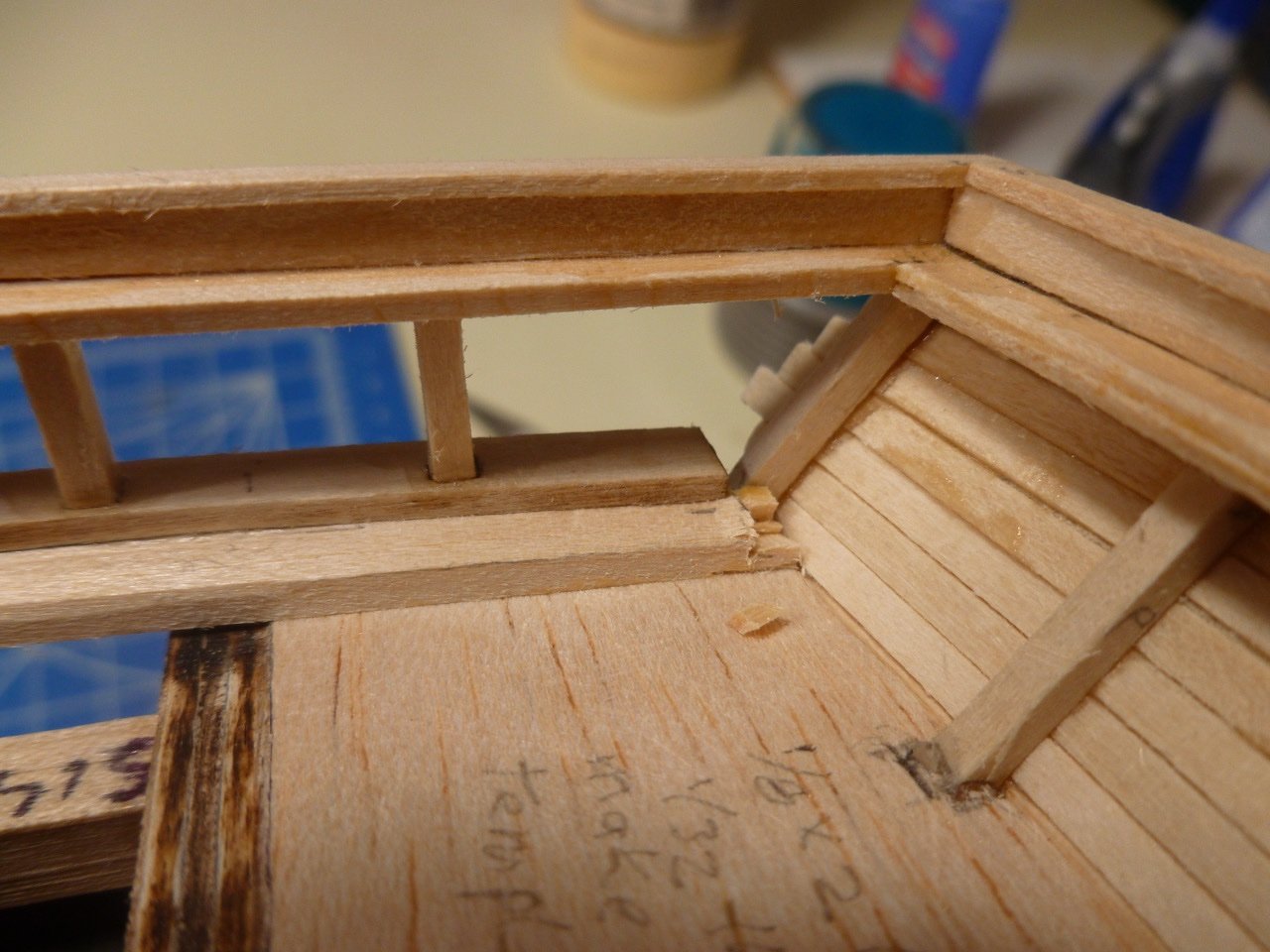
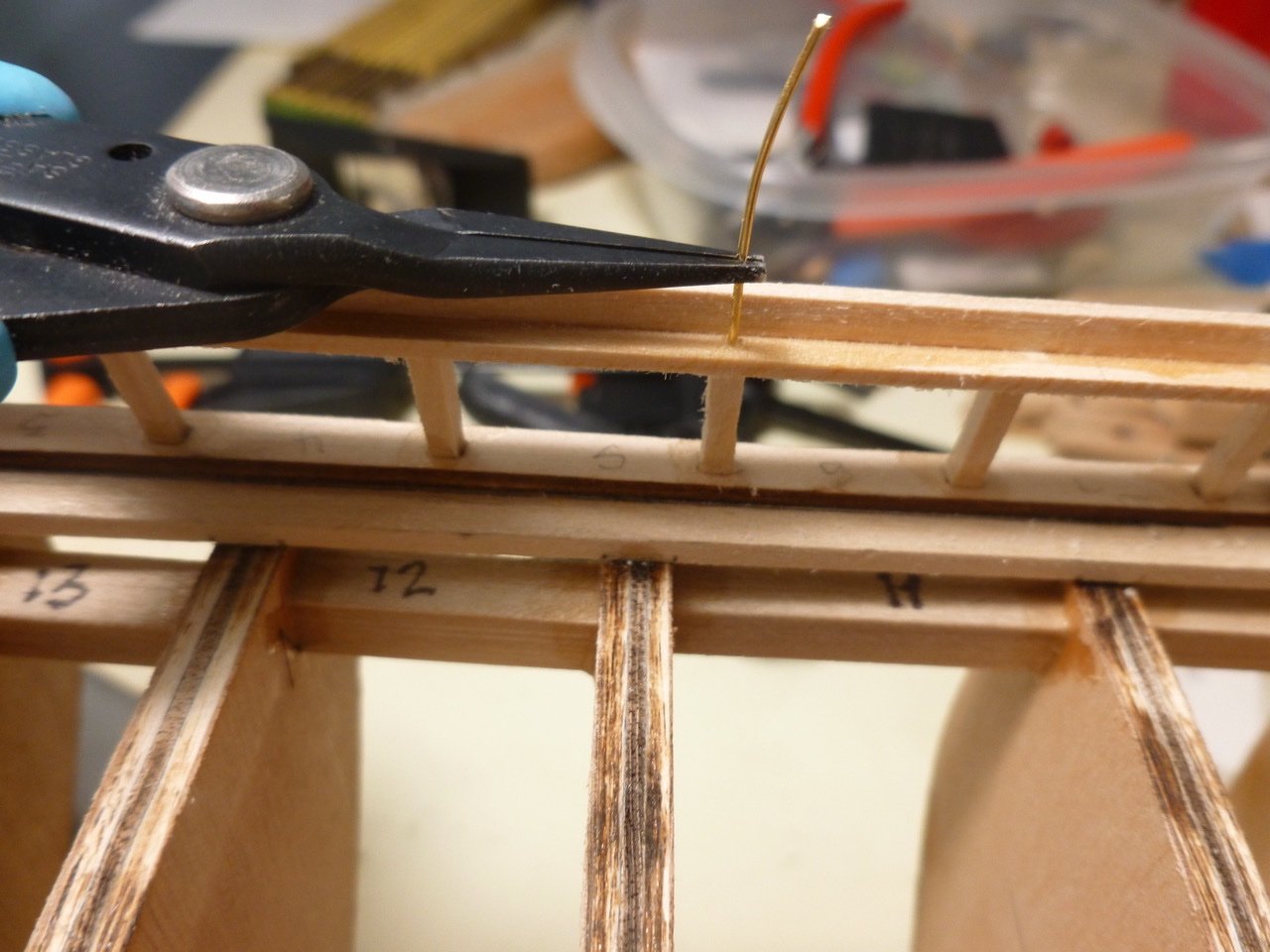
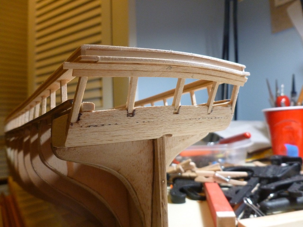
To those who dropped in or gave likes, thank you for your interest and support. Allan, I appreciate your kind remarks. The instructions refer to all parts at the bow as the stem, and include a general comment to taper it. A detail sketch showed a full taper. By the way, if knee of the head refers to something else other than the generic “stem” please let me know. I’m still learning the finer points of ship terminology. Mike, thanks also for your kind feedback. I hope you decide to pull your Morgan off the shelf. Yours was one of my go to builds while getting up to speed for this challenge. When I was about eleven and nearing my first school dance (they broke them in young back then) my mom taught me a slow step in the living room of our little old house, which had a ceiling so low that my dad, who was 6’ 3”, could reach up and place his hands flat against it. But I digress. Mom said to take one step to the left, bring my feet together, then take two steps to the right, all the while making sure my right hand was firmly planted in the girl’s back (“don’t be limp about it or she’ll think you can’t lead”). Then she showed me how those simple steps could also move you forward, backward and around in a circle. One step forward, two steps back. Good preparation for shipbuilding. While working on the port railing, a bump knocked the forward section of the starboard railing loose, popping it off the stanchions. Re-glued without further mishap, but later while studying Morgan photos I realized the railings will have a good bit of tension applied to them. Fortunately there was enough clearance to pin the main rail to every other stanchion, so I sashayed back a step and went to work with the pin vise. I’m a pinning novice so if you think it should be every stanchion please chime in. The log rail and topgallant rail are glued throughout their length and look to be structurally adequate. The pins are lengths of brass wire, of a diameter that shouldn’t split the stanchions. With forward and side railings built I moved to the transom. I made a transom main rail template using two copies of the transom plan, mirrored to show both sides. I traced this on 1/16” thick stock. When test fitted, it appeared the center framing was too tall so I trimmed it a 1/16” before gluing the rail in place. Nice and solid so I tried a piece of plank. When I viewed it edge on the railing was not only not cambered, but there was daylight between the rail and plank. Like walking across the gym to ask the pretty girl to dance, only to have her giggle and turn back to her friends. The transom framing was such a pain to install I really wanted to preserve it. So spin the girl out for a chance to regain my composure. I turned the ship over, chiseled off the plank, then cut the rail between the framing, staying well clear of each piece. When I checked the drawing for the railing camber it showed 1/16” rise at the center. Duh, just the amount I had trimmed off, but some Dremel work and each framing piece had a little hat. I made the new transom rail from two pieces of 1/32” stock, to allow for easier bending over the short length. I left the rail wide for trimming after installing the transom and ceiling planks. I cut and filed the side rails to match the transom rail profile. An interesting step since each of the three rails has a different cutback. Like a great dancer, the finished transom rail has nice curves. The transom main and topgallant rails stand proud. The rails are in and awaiting detail work at the cutting stage opening. Time for some shop cleanup. Thanks for viewing. Steve
-
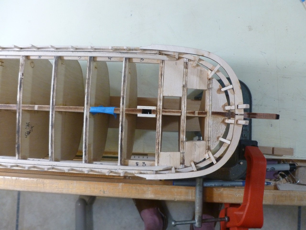
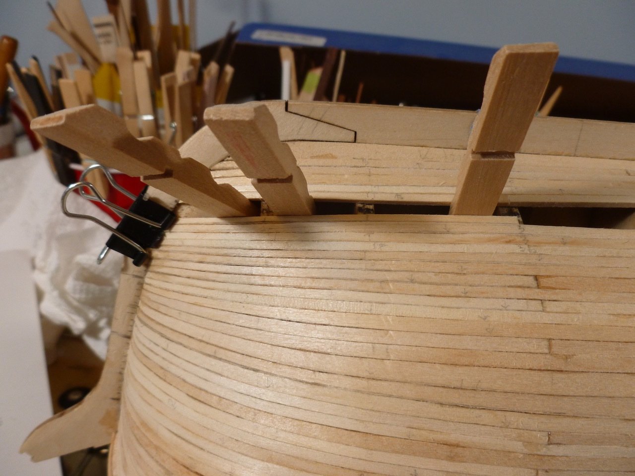
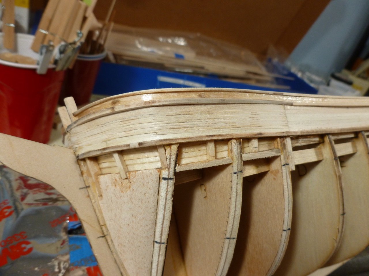
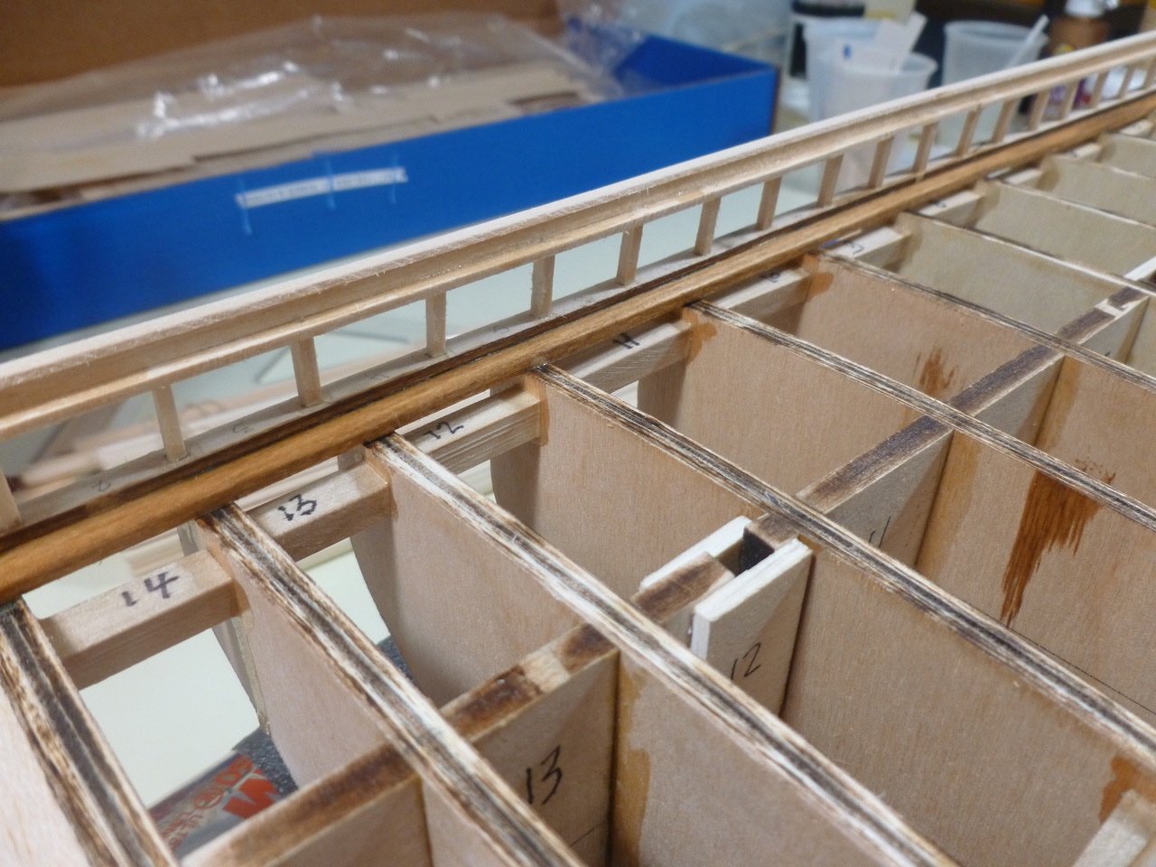
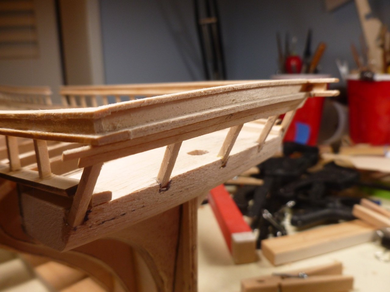
To those who dropped in or gave likes, thank you for your interest and support. This bit of nuttiness comes from trying to focus on three things at once. On the left is the main rail aft section glued and clamped. Starboard bow is the topgallant rail. Port bow is the log rail after steam iron bending, with final shaping by clamping to the inside of the curved main rail. Boy, did I think I was making progress. The instructions note that the heavily curved forward rails are laser cut but the aft rails should be formed from stripwood. Several other builds noted the difficulty in getting the main rail and planksheer to stand proud of the adjacent planking, with helpful suggestions about adding cover strips to achieve the correct overhang. Taking this as a challenge I decided to try going commando without the cover strips. The planksheer ended up slightly proud of a future plank but the jury is still out on whether it will need a cover. I resolved to do better with the main rail and the starboard forward section has a nice step to it, when measured against a sample plank. The aft main rail ran aground. The forward and aft ends were slightly proud of a future plank but the middle ran from flush to (oh no!) negative. Would this be the end of the proud experiment? Late night anxiety is not the time for thinking about corrections so lights out. An epiphany surfaced from the bowl of morning cereal. The issue with the aft main rail was in trying to bend 1/4” stock laterally. The bend was small but somewhat variable, and there was enough tension to cause the stock to slide under the clamps. But the planksheer sets the curve, and thankfully I kept the carrier sheet which contained the laser cutouts. Using the cutout holes as templates, and tracing them onto a spare basswood sheet I was able to create main rails with the correct profile. I cut them slightly oversized. So far so good. The trick now was to extract the bad rail, which was sandwiched between the log rail and the stanchions. Good fortune, patience and a cut-down clothes pin yielded a successful excision, with no broken stanchions and a reusable log rail/topgallant composite. A Dremel touch up, very light, removed the glue from each stanchion while preserving the height. The replacement rail installed much easier and has a nice sweep toward the stern, even before final sanding. But what about the original problem (stand and be proud)? Ta Da! The new main rail stands proud of a sample plank. I’m so pumped. Thanks for viewing. Steve
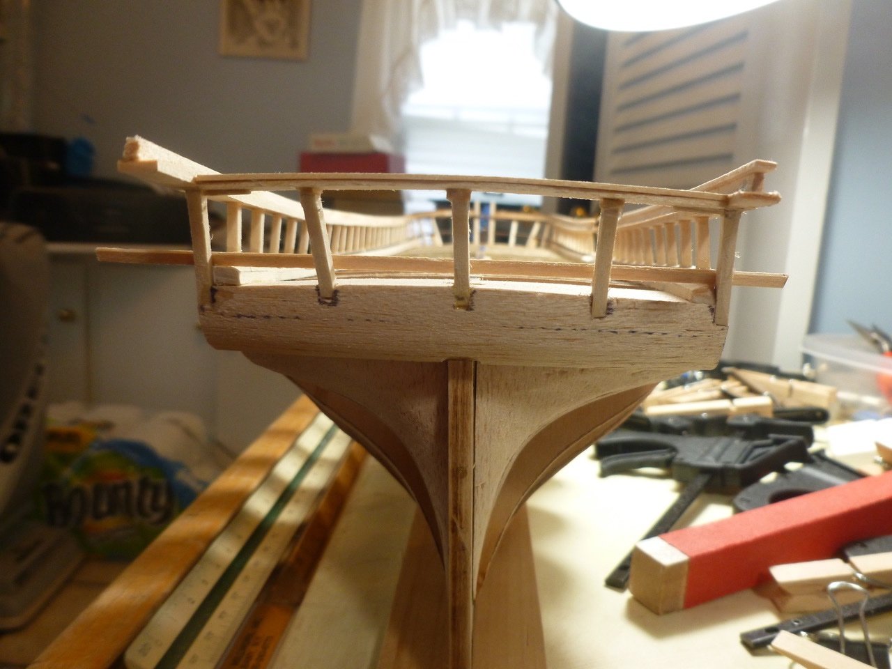
-
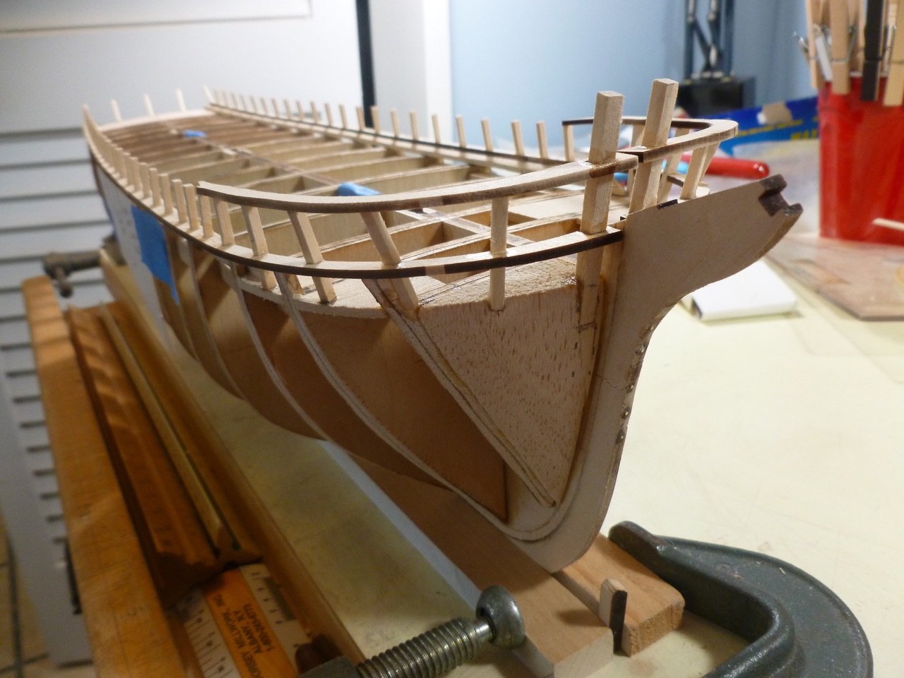
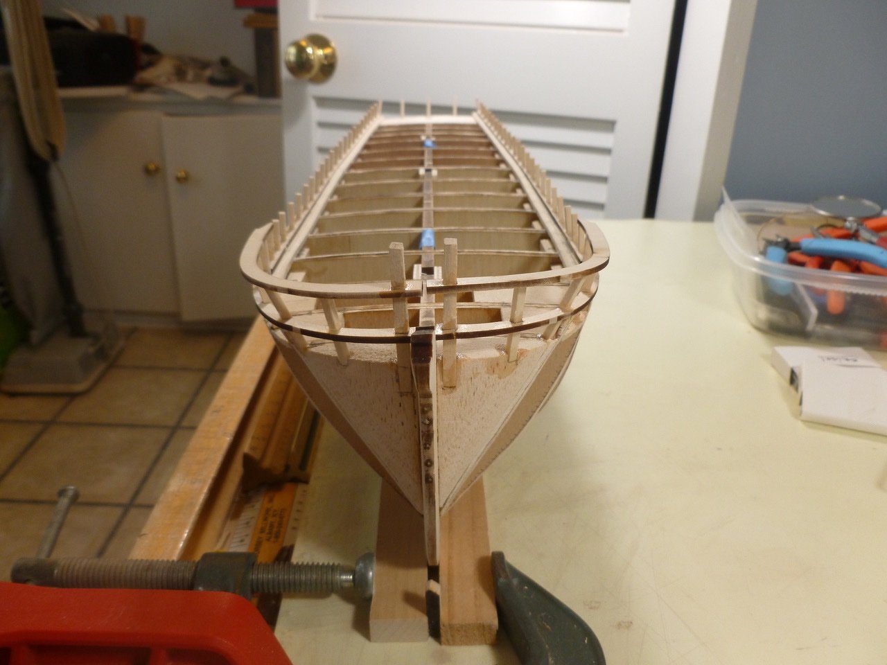
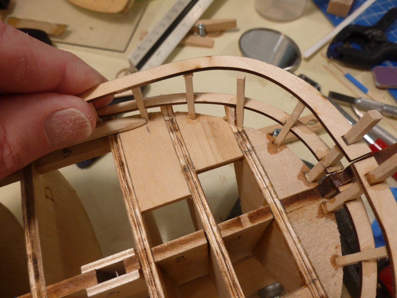
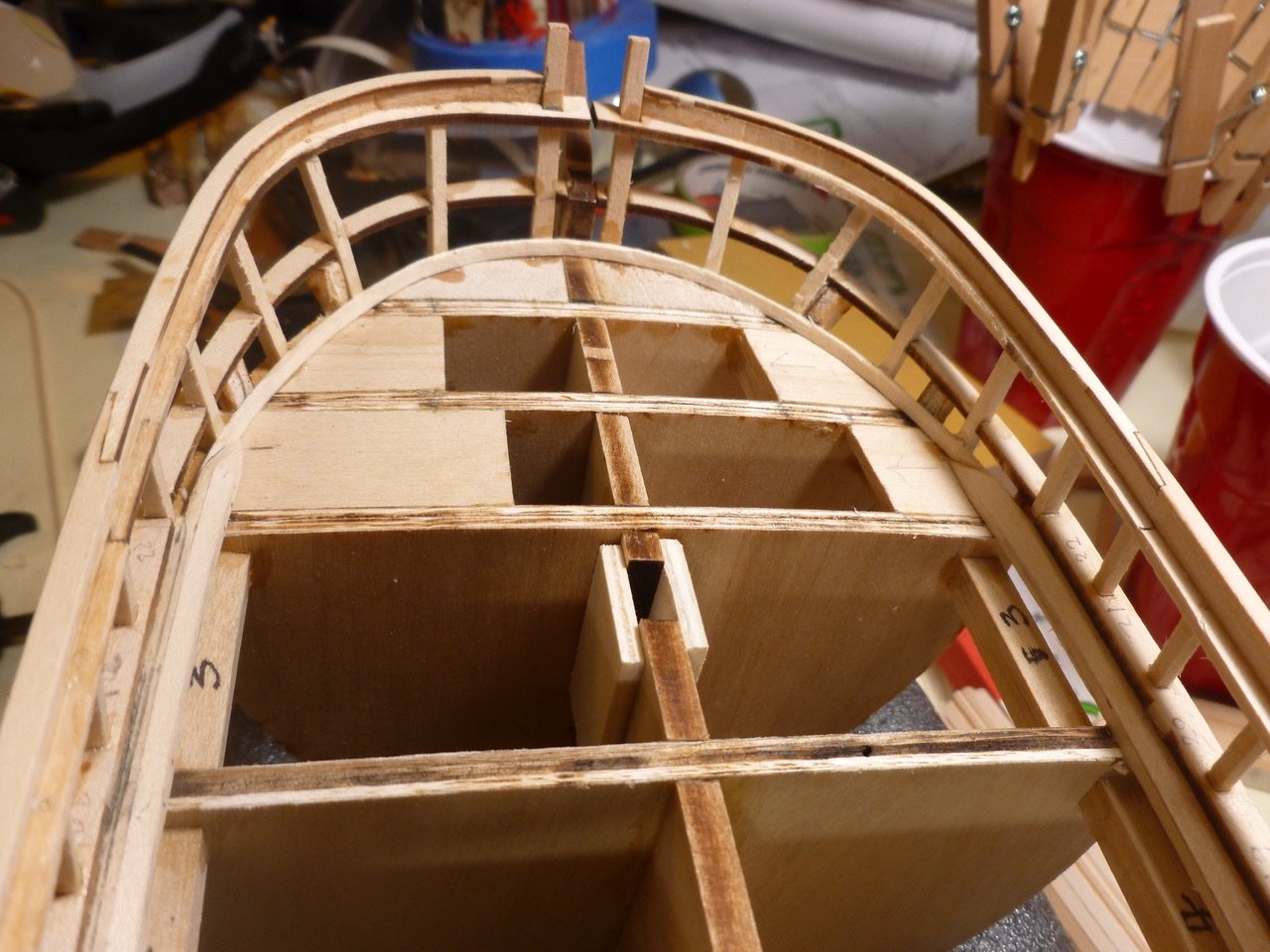
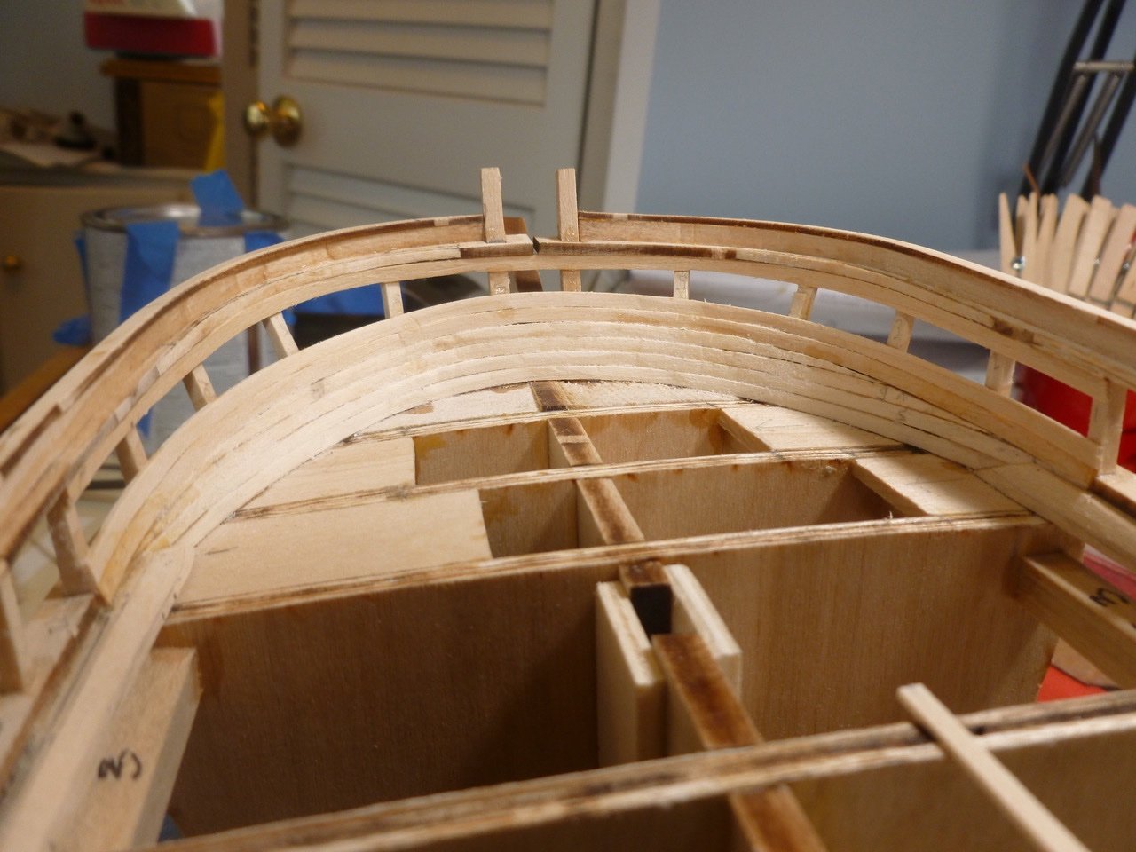
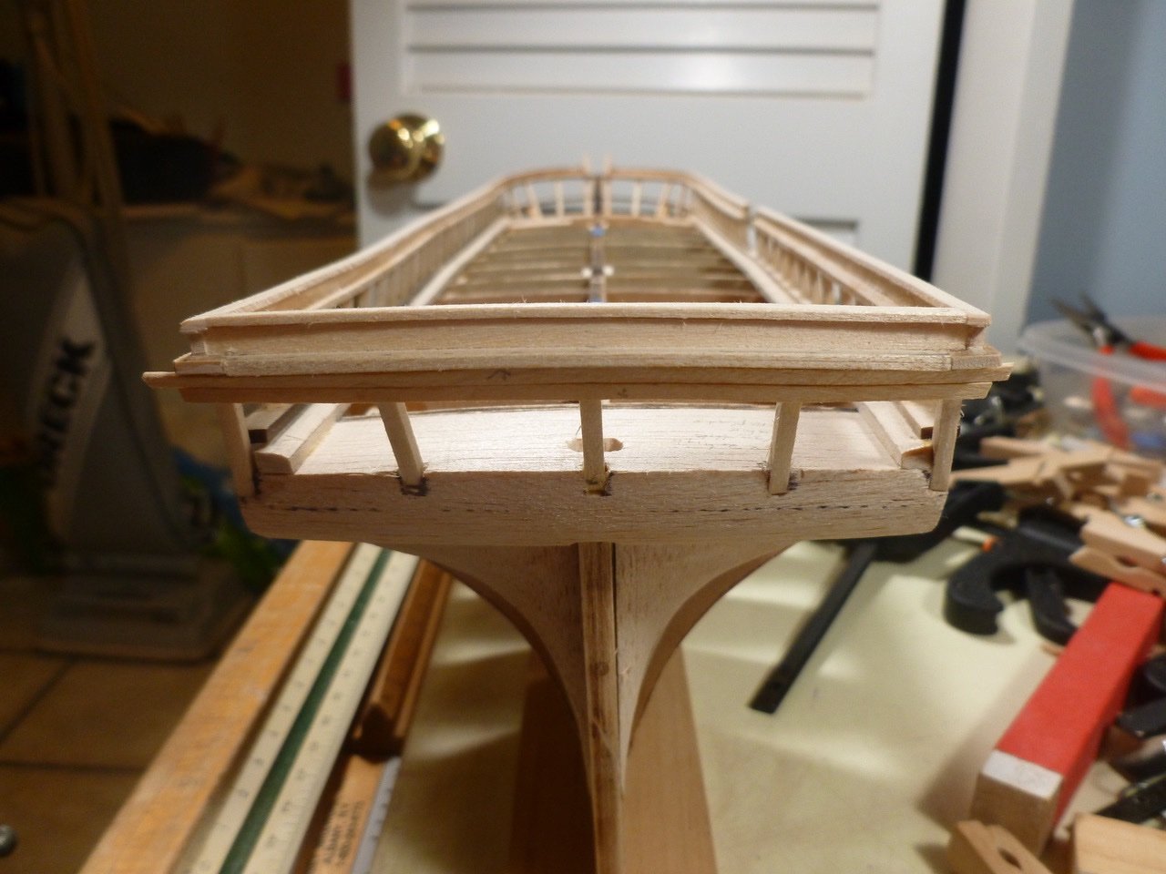
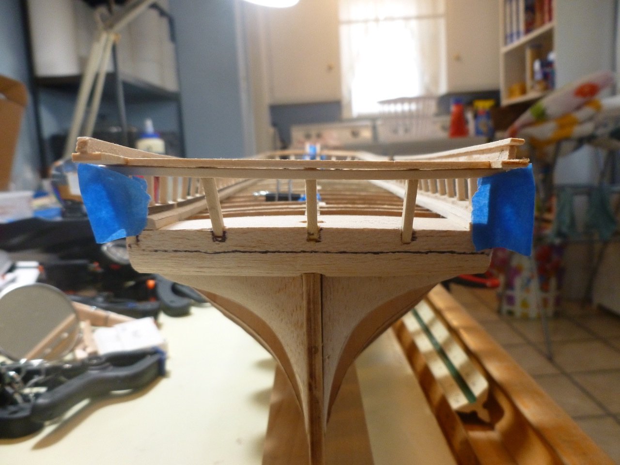
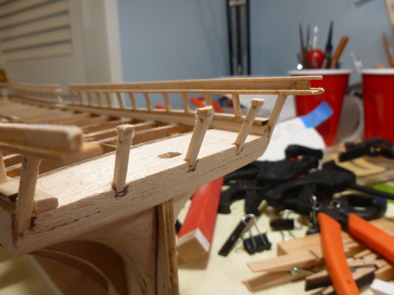
To those who dropped in, thank you for your interest and support. John, thank you for your kind comments and encouragement. I thought about wood dowels but was concerned about splitting the keel/stem because it was already thinned due to the rabbets. Work continues on the starboard stanchions. I found that gently stretched rubber bands, combined with clothes pins and a batten strip, provide enough tension to give a consistent tilt to the stanchions. I checked each stanchion with the angle template and stretched or loosened nearby rubber bands as needed. The wonky looking piece at lower left in the pic above is part of the square batten I have been using for stanchion installation. I thought I could bend it with help of water and an iron to help with timberhead alignment but 1/8" square proved a tough bend. Turns out it would have been useless anyway but I left it dangling to remind me to think hard and be careful when bending planks. The finished stanchion installation showed reasonably good alignment. The blue tape along the spine marks the bays where the spine needs to be beefed up to accept pedestal screws The next focus was the laser cut main rails at the bow. Their installation is heavily dependent on the timberhead angles. On the starboard side there was a reasonable fit once I realized I could very, very carefully stretch/bend the tail of the rail, which effectively took some of the curve out of it. Not so lucky on the port rail where two timberheads were out of line. Some very anxious cutting of CA joints allowed removal and replacement of the miscreants with new bits more willing to get in line. The installed main rails are reasonably symmetrical. The rail has a consistent slope down to the bulwark stanchions. The bow view is also reasonably symmetrical except for the repaired stem which looks like a nose that has been in a bit of a fight. Maybe I can mark that up to character building. When I placed a test rail extending from the port and starboard stanchion tops to the stern framing, it appeared the stern framing tops would need to be up a heavy 1/32 inch, relative to where it appeared they should be to align with the paper stern template. I have sanded them to that height but I’m wondering if that will cause a problem with the stern planking. The alternative would be sand them to match the template heights, and to sand a bit off a few port and starboard stanchion tops to match. Thinking ensues. Once I make a decision on the stern framing tops I can install the remaining main rails. Thanks for viewing. Steve