allanyed
-
Posts
8,064 -
Joined
-
Last visited


-
 jim Landis reacted to a post in a topic:
Need advice on US Brig Niagara carronade rigging
jim Landis reacted to a post in a topic:
Need advice on US Brig Niagara carronade rigging
-
davec reacted to a post in a topic:
Need advice on US Brig Niagara carronade rigging
-
Scottish Guy reacted to a post in a topic:
Flag with ship name reversed on one side?
-
Scottish Guy reacted to a post in a topic:
Need advice on US Brig Niagara carronade rigging
-
allanyed reacted to a post in a topic:
Chris Watton and Vanguard Models news and updates Volume 2
-
allanyed reacted to a post in a topic:
Chris Watton and Vanguard Models news and updates Volume 2
-
allanyed reacted to a post in a topic:
How to make flat rope coils?
-
allanyed reacted to a post in a topic:
How to make flat rope coils?
-

Flag with ship name reversed on one side?
allanyed replied to daschc01's topic in Masting, rigging and sails
This is an interesting question. I did not realize schooners flew pennants with the vessel's name on it but assuming they did, why would the name be backwards on one side? Weren't the letters painted or sewn on each side? If that is the case, there is no reason to have one side backwards. I am curious to know if they actually flew pennants with the name and if so, were they backwards? Allan -
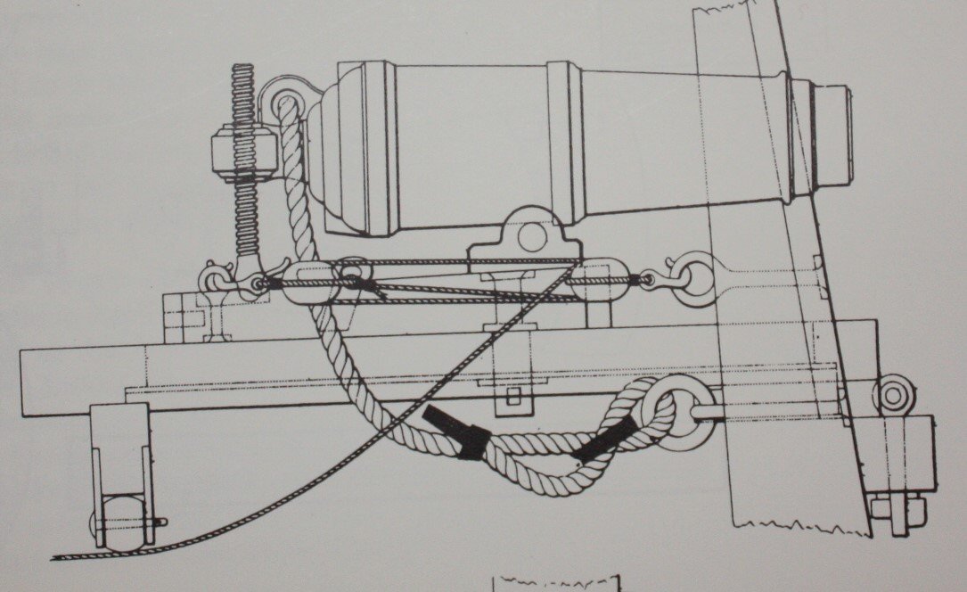
This is not to say the Americans followed the same practice, but from Caruana's The History of English Sea Ordnance, volume II, page 204, including the drawing below, the following is taken from Dupin. Dupin stated that the rigging is based on details taken off, with great exactness, from carronades in vessels taken by the French from the English. The drawing shows that there is one breeching rope as well as one running rigging line, not two, on each side. Of course there may have been be exceptions or variations as is often the case. Note that the blocks are secured to eye bolts with hooks rather than being tied to them. Allan
-
Canute reacted to a post in a topic:
Choice of books
-
oakheart reacted to a post in a topic:
HMS Sphinx 1775 by mugje - Vanguard Models - 1:64
-
Thukydides reacted to a post in a topic:
HMS Sphinx 1775 by mugje - Vanguard Models - 1:64
-
 mugje reacted to a post in a topic:
HMS Sphinx 1775 by mugje - Vanguard Models - 1:64
mugje reacted to a post in a topic:
HMS Sphinx 1775 by mugje - Vanguard Models - 1:64
-
allanyed reacted to a post in a topic:
Lady Nelson by Danstream - Amati/Victory Models - 1:64 scale
-
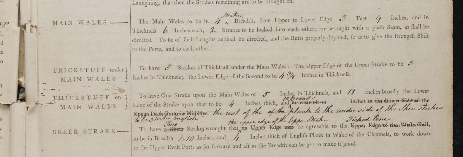
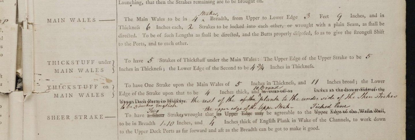
Your planking is exemplary! The only thing that looks a bit different is there are no wales. I am guessing you will put a third layer of planking to represent the wales so you may find the following information on planking from the contract for Perseus (20) and Unicorn (20) 1776 interesting. Allan Plank of the Bottom The plank of the bottom to be 3 in thick of English, the best of its kind from the light draught of water up, cut regular & well seasoned no plank to be wrought less than 23 ft in length between the fore & after shifts to have 3 strakes between every 2 butts on the same timber & none less than 5 ft 9 in scarph but in general to be 6 ft & the plank to run 24 ft in length. Main Wales The main wales to be in breadth from the upper edge to the lower edge 2 ft 10 in & in thickness 5 in to be worked in 3 strakes of such lengths & the butts properly disposed so as to give the strongest shifts to the ports & to each other. Thickstuff under the Wales To have two strakes of thickstuff under the main wales, the upper edge of the upper strake to be 3 ¾ in thick, the lower edge of the second to be 3 in in thickness. Thickstuff upon the Wales To have one strake upon the main wales of 3 ¾ in thickness & 10 in broad the lower edge of the strake upon that to be 3 in thick & to wear off to 2 ½ at the lower sill of the upper deck port and at the top of the side or lower edge of the sheer strake 2 ¼ in.
-
allanyed reacted to a post in a topic:
HMS Sphinx 1775 by mugje - Vanguard Models - 1:64
-
allanyed reacted to a post in a topic:
Helping hands vice
-
allanyed reacted to a post in a topic:
Avoiding Chipping while Milling Hardwood
-
allanyed reacted to a post in a topic:
Choice of books
-
Mr Whippy reacted to a post in a topic:
HMS Sphinx 1775 by mugje - Vanguard Models - 1:64
-
B-25J Mitchell by Chadwijm6 - HK Models - 1/32
allanyed replied to chadwijm6's topic in Non-ship/categorised builds
One of my all time favorite planes. Luckily I got to see one up close and personal and get on board the B25 owned by Ed Browing's Red Baron Flying team which sponsored Daryl Greenamyer's low altitude speed record flight over Mud Lake, Nevada. Great story and one of the greatest thrills of my life to work for one of the sponsors and be there to see it in person. A bit off topic but for an interesting read - https://www.916-starfighter.de/F-104RB_RedBaron_AirProgress1977.pdf Allan -
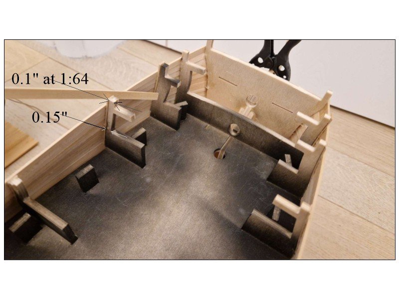
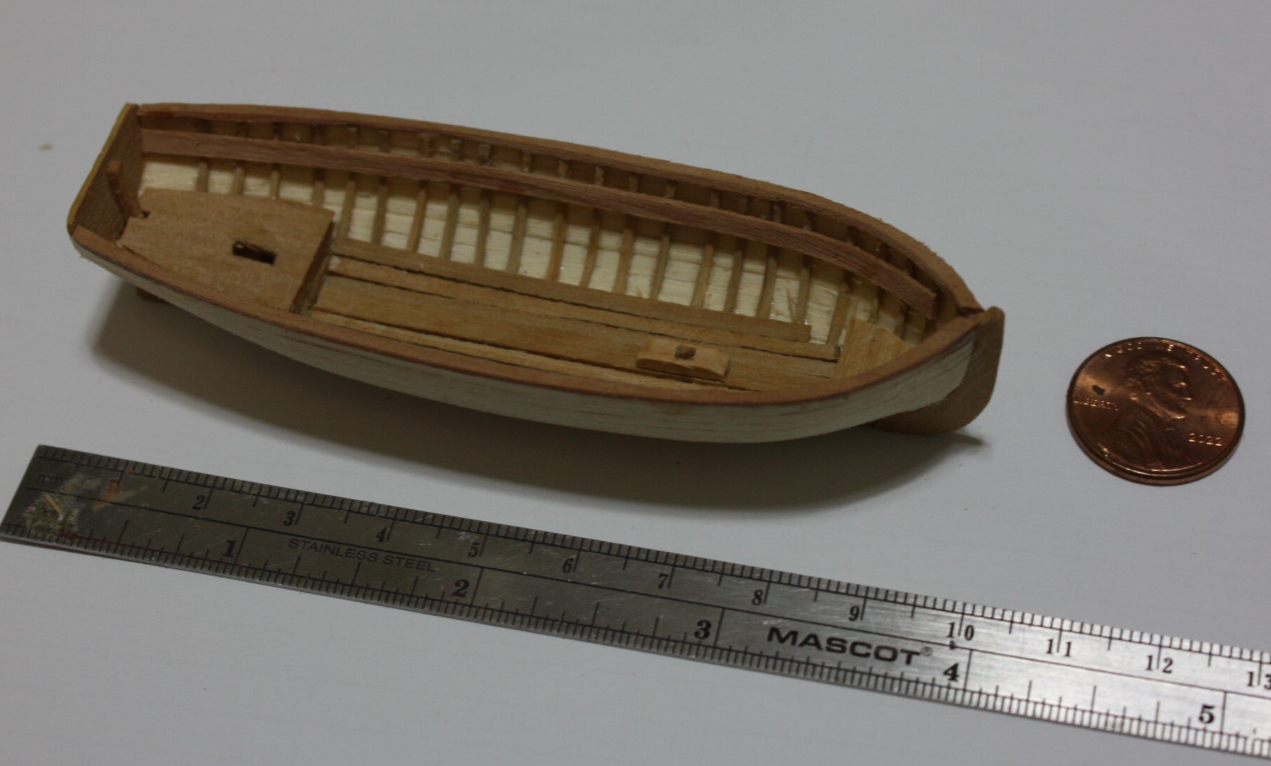
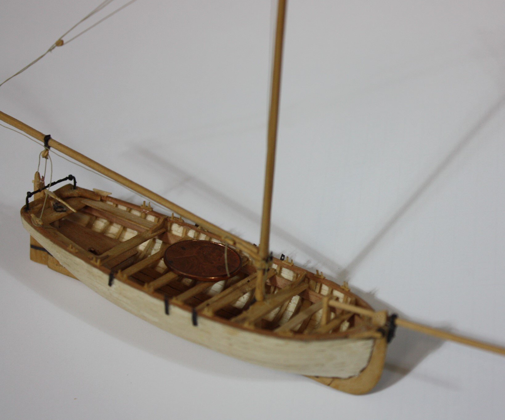
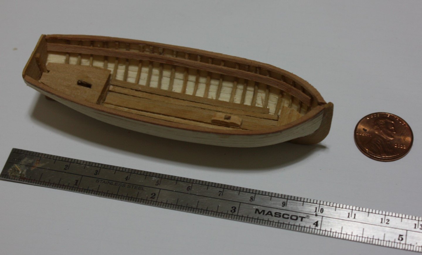
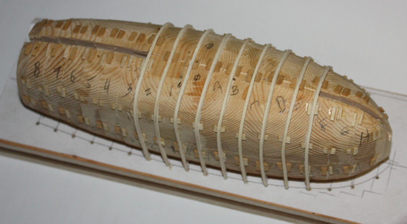
Hi Lucien, Many of us scrap first and second attempts so you are not alone by any means. One small suggestion, the plug looks to be grooved similar to the method Frolich details in his book The Art of Ship Modeling. I found this to be troublesome with the frames getting stuck in them at times. An alternate is to leave the plug smooth and glue tiny spacers where the frames go. Just need to be sure they are shallower than the frames. For scantlings of every part of many types of English boats, W.E. May's book Boats of Men of War is a great help. The below is 1:128 scale 31 foot long boat using the plug method so it can be used at least down to that scale. The last photo is a larger plug (1:48) that shows the spacers. Allan

-
Exactly what I was going to write. Well said. I have two books by Endsor and for the 17th century they are fantastic. For overall usefulness, at least for English ships you have the the three I would put up at the top of the list, Lees (Masting and Rigging), Lavery (Arming and Fitting) , and Goodwin (Construction and Fitting) For scantlings- Steel's Elements and Practice of Naval Architecture, The Shipbuilder's Repository (1788) and the Establishments although these can be very expensive. These have been put together all in one book available from Seawatch Books. TFFM by David Antscherl offers a wealth of information on "how to" that is applicable in many ways to a host if ships, not just the Swan class around which it is centered. Allan
-
That was my go to as well and it works very well. Alternatively I found a hot air gun works more easily for me. Either way, the methodology is the same and gets the job done. There are a lot of choices of guns from Genesis to Bosch at reasonable prices from many stores or on line. Allan
-
I agree that the steersman did not sit on the aft most thwart. This boat is single banked so there would likely be three tholes on each side for the six rowers. The last drawing showing two tholes MIGHT be a mistake. Looking at contemporary models and drawings in W.E. May's Boats of Men of War and more in the RMG Collections, so far, I cannot find an odd number of tholes on any boat. Out of curiosity do the other six boats that Beagle carried show this oddity? Allan
-
Have you or any other member tried scraping rather than sanding these oars? Similar to scraping a planked hull or deck, a stiff back razor blade or scalpel blade can be controlled more easily at times and might give you better results. Allan
-
David Your perseverance is commendable! It may be the photo but if the two thick tape lines are the top and bottom of the wales and black strake above the wales it looks to be very close to where it shows on the contemporary drawings forward. At the stern it appears to be a bit high but again, it may be the photo. The line of the wales can be seen clearly on the high res drawings on the Wiki Commons site (https://commons.wikimedia.org/wiki/Category:Ship_plans_of_the_Royal_Museums_Greenwich pages 4 and 5) as well as on the photos of the model at RMG Collections of the Apollo/Artois class of which Diana is a part. https://www.rmg.co.uk/collections/objects/rmgc-object-66303 There are low res drawings on this site but the high resolution version on Wiki Commons are often more helpful. The bottom of the wales aft is about 77 inches below the bottom of the aft most gun port opening. The bottom of the wales is 84 inches below the bottom of the forward most gun port opening. For the wales and strake on the wales, the dimensions from the contract are below. I may be mistaken on this particular ship, but often the first strake of thick stuff (in this case, one strake) above the wales is black as well as the wales. Allan
-
Welcome to MSW Eric. Loved your intro! If your models are as well done as your introduction, you will have great success. Regarding your first build choice
-
Bending hard brass.
allanyed replied to navarcus's topic in Metal Work, Soldering and Metal Fittings
Angel, It looks like your prop is in the wrong place or the diameter is too large. Is it possible to relocate the propellor shaft or go with a smaller diameter prop? Also, you can add a piece similar to the sketch below although it is probably not a good solution. If the ship had a wooden keel then this would work well and could also take a false keel across the entire length of the ship as well. Can you tell us which vessel this is? Thanks Allan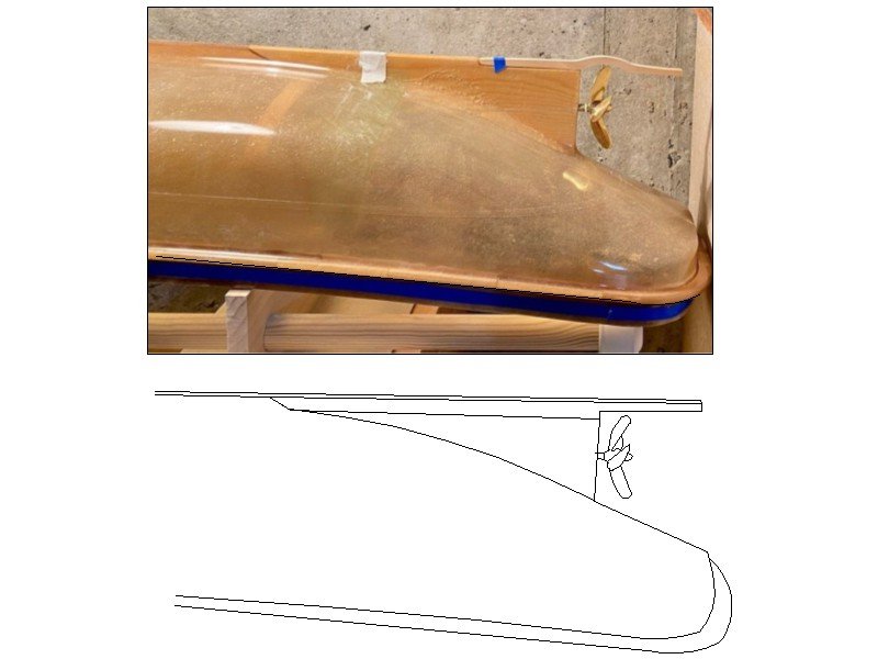
-
Similarly you can draw a box that is any given dimension in both the x and y axis such as 4 or 5 inches (100 or 150mm) somewhere on the drawing that you want to have printed. Once the drawing is printed, check the length and height of the scale box with a vernier caliper to confirm the printed plan is accurate. For larger drawings I like to use architectural engineering printer shops and ask them to check the scale box on the printed sheet. They have rarely had to make minor adjustments. I have also gone to Fedex offices that have large format printers. More often than not they have had to make small adjustments to get accurate results which they were happy to do. For those that do not do their own drawings but get prints from RMG and other sources, the copies are suspect as the original plans are often distorted to some degree which is not surprising after a few hundred years. Allan
-
Bending hard brass.
allanyed replied to navarcus's topic in Metal Work, Soldering and Metal Fittings
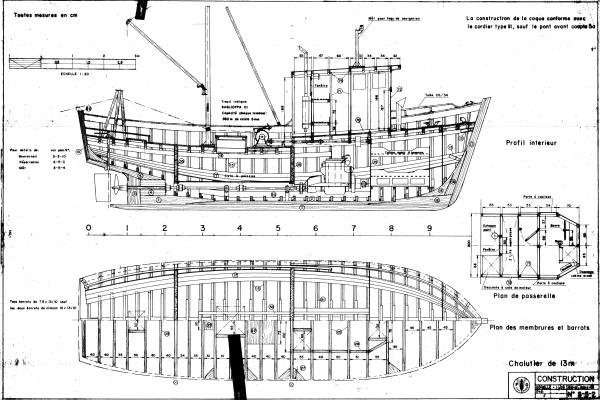
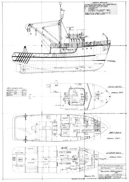
Looking at drawings of various trawlers and boats I still cannot figure out what Navcus is looking for. Attached show skegs that are below the prop so I assume (usually a bad idea) it is this area. If the skeg has to be bent to clear the prop it seems like the prop reaches below the keel which is odd for these boats. Hope he or she posts a drawing as now I am curious.🤔 Allan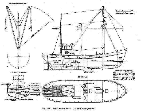
-
This might help. From the Shipbuilder's Repository 1788 which should be close for Agamemnon 1781: Fourth futtocks moulded at the upper deck 9 3/4" Top timbers <at the top end> moulded in the range of the forecastle 5 1/4" The dimensions below are what they would be if made to scale 1:64 This would apply to the forward frames as well. It looks like the forward most frames moulded dimension is too heavy. Perhaps the kit has it extra thick due to the pressure of the planking bend in that area. Allan